The erecting device of force transducer and weighing scale
Technical field
The weighing scale that the present invention relates to the erecting device of force transducer and comprise the force transducer that is fixed together with described erecting device.
Background technology
The load-sensing unit of weighing scale is equipped with a force transducer usually, and this force transducer is connected to one as the scale frame of bearing in a side, is connected to the tray rack of weighing at opposite side, and the power that will measure is introduced by this tray rack of weighing.Can be configured force transducer in many ways.Widely used is to be designed to have a sensor as the elastic deformable body of core parts, or has the equipment that carries out force compensating (in most of the cases being to utilize the equilibrant that is produced and worked by a leverage by a Current Regulation electromagnet).
For instance, as in list of references [1], DE 199 39 633 A1 are described and in list of references [2], the force transducer that is called " reacting force spare " or " beaer " among EP 0 670 479 A1 has an elastic deformable body, this elastic deformable body is connected to a force action part with the fixed part that one of sensor is installed on the scale frame, for weighing scale, then be to be connected to a load functional component.In general, force transducer has some lateral trenchs on the intermediate location between deformable body and the some parts, and these some parts are used for this force transducer is connected to this scale frame and the tray rack of weighing.These some lateral trenchs are used for mechanically throwing off this deformable body, in this deformable body, utilize sensor (preferably utilizing strainmeter) to measure by the caused distortion of acting force.
This deformable body preferably is configured to the measuring sensor of a parallelogram shape, and this measuring sensor has a ways (for example referring to list of references [3], EP 0 511521 A1) that is similar to parallelogram.
The simulating signal that representative is measured is produced by strainmeter, and this strainmeter preferably is connected with each other in a bridgt circuit.Usually this signal of digitizing also carries out more treatment step to it subsequently in a change-over circuit.List of references [4] for example, U.Tietze, Ch.Schenk, Halbleiterschaltungstechnik, reprints for the first time by the 11 edition, Springer Verlag, Berlin 1999, the 1242-1243 pages or leaves have described a kind of basic structure of the bridgt circuit with strainmeter.
For supporting the further processing to the digitizing measuring-signal, the measuring sensor described in the list of references [2] has the memory module of a storage characteristic parameter, and these characteristic parameters all are specific for each measuring sensor, and are used for the correction of measuring-signal.
As list of references [5], described in the disclosed patented claim GB 1 462 808, aforementioned correction especially is applied to owing to non-linear, hysteresis phenomenon, temperature and the caused error of creep effect.During factory makes, determine to revise required calibration and offset data and be stored in the memory module by special test and measuring process.
According to list of references [1], the measuring accuracy of force transducer depends on the hysteresis characteristic of force transducer to a great extent in the weighing unit.The hysteresis characteristic of force transducer is caused by the some factors that occur simultaneously each other under most situation.
Again according to list of references [1], the Machine Design measuring method that is used to alleviate lag-effect up to now mainly concentrates on the elastic deformation of avoiding the force transducer material.As a kind of avoid force transducer be connected on the scale frame fixed part and with its mounting base that is connected between the method for friction force, with these two parts tightly together with bolt, and be bonded together by surface in contact, this surface in contact is polished down to a high-precision flatness and removes railway grease and other impurity.Hysteresis error for the restriction scale is necessary to require the machining of surface in contact and the tightening torque of bolt to reach specified level.
In the practice of these requirements, have been found that to be threaded in and brought variable stresses in the material, and hysteresis phenomenon is had extra adverse effect.
A solution has been proposed in the list of references [1]: force transducer with respect to the scale frame to insert the shim elements of a flat resilient seal material between fixed form mounted component and the mounting base that should fixing force transducer parts be connected.Yet, in this solution, except the cost of this encapsulant, also to consider the long-term behaviour of this shim elements.In some cases, be equipped with the scale of an elastomeric pad element after short relatively period, may need to recalibrate.
In addition, novel scale all has usually and can just can be changed at the user place and be need not scale is returned the modularization load-sensing unit of factory by trained service personnel.The elastomeric pad element is difficult in to change under the condition that need not to recalibrate after the load-sensing unit and is applied to these scales, because along with the replacing of load-sensing unit, very violent variation can take place this elastomeric pad element.
Summary of the invention
Therefore, the purpose of this invention is to provide a kind of scale that is used for the improvement erecting device of force transducer and has the force transducer that utilizes this improvement erecting device installation.In this article, term " erecting device " comprise be used on the whole to interconnect the introducing of scale weigh load parts and the mechanical component of the force transducer between the pedestal of balanced support power is provided.
The present invention particularly attempts to provide a kind of force transducer that has cost-effective erecting device, this erecting device makes the force transducer that has some sensors to install by this way, thereby thereby measurement characteristics is the linear very little deviation of also having only to a great extent needs compensation.In addition, as time goes by, after the installing force sensor, still can keep and an ideal behavior between deviation should change as small as possible.
Another object of the present invention provides a kind of erecting device that allows in the very little space that load-sensing unit is installed in the scale frame and have high stability.
The another purpose that is used for a preferred embodiment of this erecting device is to protect load-sensing unit to avoid overload reliably.
In addition, this erecting device is applicable to the installed module load-sensing unit, and this load-sensing unit need reach and need not to recalibrate the requirement that scale just can be changed.
For achieving the above object, the present invention proposes a kind of erecting device of force transducer, wherein this force transducer comprises a force action part, one support unit, and one between this force action part and this support unit and have a core component of at least one sensor, this erecting device comprises that the load that one first attaching surface by this force action part is connected to this force action part accepts parts, and comprise that one is connected to the securing member of this support unit by one second attaching surface of this support unit, wherein, securing member has the U-shaped cross-section of the open side of its U-shaped profile towards force transducer, securing member from second attaching surface of this support unit towards force action part and the center of crossing core component extend, and on this securing member, provide the parts that are used for fixing this securing member.
In addition, the present invention also proposes a kind of scale with aforesaid erecting device.
This force transducer is equipped with force action part and the support unit that links to each other by a core component usually.This core component has at least one sensor, and can be by lateral trench and this force action part and/or the decoupling of support unit machinery.According to the present invention, the distinguishing feature of force transducer is the specific arrangements of several threaded bore, and these borings accommodate to be accepted parts with load and be attached to the force action part of force transducer and the trip bolt that a securing member is attached to the support unit of survey sensor.
This distinguishing feature that is used for the creative erecting device of force transducer (the especially force transducer of the above-mentioned type) is that one has the securing member of U-shaped cross-section, and wherein the open side of this U-shaped cross-section is towards this force transducer.This securing member extends towards force action part from the attaching surface of support unit, and crosses the middle part of core component, and comprises that several are installed in the device of a fixed position with this securing member, for example screw, anchor clamps, snap connection or similarly fastener.These erecting devices are used for load-sensing unit is attached to the parts that in most of the cases keep static, especially for example on the scale frame of weighing scale.Preferably, securing member comprises the device that the force transducer of this securing member and an aforementioned type can be threaded togather.More preferably, the load that is also referred to as the tray rack of weighing under the particular case of weighing scale is accepted parts and is configured in the same way as described above similarly be connected to force transducer by bolt.Yet this special feature for example can not be applied to directly to be threaded into the hook of this force action part and to introduce the scale of load from a suspended load by one.
In this erecting device, support unit is connected to a securing member, and this securing member can suitably for example be fixed in the scale frame of scale again.Therefore, in the overwhelming majority of force transducer used, support unit can be mounted in the part of force transducer of a fixed position of scale frame.As another characteristics of this erecting device, force action part is connected to a load and accepts parts.For scale, it is the tray rack of weighing that parts are accepted in this load.
Parts self are accepted in securing member and load also should be hard as much as possible, and should have the device that is used for for example installing at the scale frame of scale the force transducer that is equipped with this erecting device.According to of the present invention one preferred thinking, the supporting member that parts are configured to have the U-shaped profile and are formed with overhanging flange on the side of U-shaped passage is accepted in securing member and load.This lateral lip can provide rigidity.For securing member, this lateral lip also provides securing member has been connected to outside possibility.They also allow one to have the layout of hanging down the overload protection of overall installation profile.In addition, but U-shaped supporting member protection sensor when processing module.
From list of references [6], can also learn among publication application DE 199 10 003 A1 that force transducer and strainmeter all are extremely sensitive elements, it is easy to be damaged by mechanical overload.Therefore, the described equipment of list of references [6] has an adjustable terminal stop part, and it is arranged on the fixed part that is connected in the scale frame of force transducer, be used to limit weigh pallet or the weighing platform fixed by the tray supporter of weighing to bottom offset.In the modularization force transducer of type described in the list of references [2], there is not a kind of favourable mode can realize this configuration of overload equipment, this overload equipment needs relatively large space in vertical direction.Because weighing platform and overload devices tend are in the mode of working together, the design alternative of scale is very restricted.When changing measuring sensor, the gap between terminal stop part and the weighing platform may need to readjust.And, in the described equipment of list of references [6], the power that is acted on weighing platform by the terminal stop part and the load of weighing not is consistent with a common axis, therefore after reaching the terminal stop part, one can not continued to act on the force transducer by the component of terminal stop limits, this elastic performance for force transducer has adverse effect, if perhaps acting force reaches maximum and acted on a disadvantageous moment of torsion, what for to the damage that can cause force transducer.
Above-mentioned shortcoming can should be avoided in the preferred embodiment of creativeness erecting device of the present invention.Be the overload of the force transducer of avoiding being equipped with sensor, the flange that load is accepted on parts and the securing member sidewall extends enough far towards the other side each other, thereby makes their mutual overlappings.On overlapping region, be furnished with the terminal stop part that cooperatively interacts, to prevent to be used as when firmly too big force action part with respect to the over-travel stroke of support unit.For example, weigh tray rack one or more generally term one load at least one position that extends laterally of accepting parts be equipped with a circular hole, a vertical bolt passes this circular hole with a gap.Two nuts on this bolt are adjustable, its regulative mode make a nut restraint functional component to bottom offset, the displacement that the restriction of another nut makes progress upward.Within the scope of the invention, other possible structural arrangements of the terminal stop part on the overlapping parts is easy to imagine and obtains.
Because the terminal stop part acts directly on the tray rack of weighing, therefore can under to the condition of space requirement minimum, realize this overload equipment.Because weighing platform or the pallet of weighing directly do not match with this overload equipment, this overload equipment for the design of scale without any restriction.
Preferably, securing member and load are accepted parts and all are equipped with a terminal stop part that is used for two sense of displacement in its both sides.For example, the tray rack of weighing can have the side male part in its both sides, and each side male part has a circular hole, and a vertical bolt passes this circular hole with a gap.Two nuts on each bolt all are adjustable, itself so that form respectively downwards and upwards two nuts of restriction end meet with these two side male part simultaneously, thereby the hysteresis problem that can avoid the side of force transducer to change and cause owing to twisting action.
The power of load and the danger that has prevented with the bolt shaft of overload equipment axis in the same plane layout in alignment that the component relevant with load continues to increase after both sides had all arrived the mounted terminal stop part and force transducer is had a negative impact on this tray rack of weighing.
Tray rack and the securing member preferred disposition of weighing has the U-shaped cross-section of the opening edge of its U-shaped passage towards force transducer, thereby makes force transducer partly be surrounded owing to its U-shaped shape has the parts that strengthen rigidity by these.Therefore, its internal fixation has the erecting device of measuring sensor also can be used for the trebuchet of strict accuracy requirement.
The end of preferred U-shaped securing member extends in the bandy alar part in the side, is equipped with the through hole that several are used for mounting screw on this alar part, and these screws can screw in the supporting member of scale frame.Therefore, the securing member in the present embodiment also provides a reliable maintenance effect simultaneously on force transducer, realizing a simply effectively overload equipment, and whole measuring equipment is connected to the scale frame.On the contrary, solution suggested in the prior art is (referring to for example list of references [7], publication application DE 198 36 317 A1) include an extra base plate, measuring sensor is connected to the scale frame for example on the thin metal parts of a mold pressing, it will inevitably bring the increase of manufacturing cost and need be installed in the sizable scale frame.
Therefore, this force transducer preferably is connected to foregoing tray rack and the securing member of weighing.Yet this does not also mean that to get rid of to use to have the possibility of difform weigh tray rack and securing member.
Description of drawings
The present invention will be described in more detail below with reference to the accompanying drawing of an example of load-sensing unit, and this load-sensing unit has a deformable body that is configured to have the parallelogram measuring sensor of some sensors.Yet, shown in example be not limitation of the scope of the invention.The present invention also can be used for the load-sensing unit of other types.
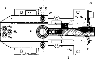
Fig. 1 illustrates a force transducer 20 that utilizes an erecting device to install, wherein, this force transducer and sensor 28,29 and circuit module 24 constitute a modularization load-sensing unit 2 together, this modularization load-sensing unit 2 can be connected to a tray rack 4 and be connected to a scale frame 5 by a securing member 3 of weighing that is used to the power that applies;
Fig. 2 shows the side view of modularization load-sensing unit 2 shown in Figure 1;
Fig. 3 illustrates the force transducer 20 of modularization load-sensing unit 2 shown in Figure 1, and it has the screw 36 that is respectively applied for connection securing member 3, weigh a tray rack 4 and a hardware
BR, 36
BL, 36
F46
BR, 46
BL, 46
F231, this securing member 3 is connected to a scale frame, and this hardware is used for the holding circuit module;
Fig. 4 shows the front elevation of modularization load-sensing unit 2 shown in Figure 1, and it has force action part 206;
Fig. 5 illustrates the vertical view of modularization load-sensing unit 2 shown in Figure 1, and it has two banded connectors 22
T, 22
B, circuit module 24 is connected to some sensors by these two banded connectors;
Fig. 6 schematically shows the modular construction of a preferred circuit module 24, and this circuit module is by connector 22
T, 22
T`, 22
BBe connected to sensor 28
TF, 28
TB, 28
BF, 28
BB, and be connected to a processing module 501 by another banded connector 500.
Embodiment
Fig. 1 and Fig. 2 illustrate a force transducer 20, and it forms a modularization load-sensing unit with sensor 28,29, and it utilizes an erecting device according to the present invention to install.Force transducer 20 is by mounting screw 36
BR, 36
BL, 36
FBe connected to a securing member 3, and by mounting screw 46
BR, 46
BL, 46
FBe mounted to the tray rack 4 of weighing.The band shape of circuit module 24 by two separation device 22 that is flexible coupling
T, 22
BBe connected to sensor 28,29, and fixing by an angled metal element 23, and this hardware is connected to force transducer 20 by a screw 231, to guarantee the good heat exchange between circuit module 24 and the force transducer 20.
As mentioned above, force transducer 20 and strainmeter 28
TF, 28
TB, 28
BF, 28
BB(referring to Fig. 3) is extremely sensitive element, is easy to be damaged by mechanical overload.A preferred embodiment of the present invention provides a plain mode of realizing overload protection, the upper and lower displacement stroke of its restraint sensor 20 and do not allow to occur on the force transducer harmful torque reaction.
As can be as seen from Figure 4, in order to implement the creative thinking of this overload equipment, the U-shaped profile tray rack 4 of weighing has sidepiece 43, the 43` that has hole 44,44`.The bolt 33, the 33` that are connected to securing member 3 pass hole 44,44` with a gap.Two nuts 34,35 on the bolt 33 and two nut 34`, 35` on the bolt 33` are adjustable, so that the force action part 206 of first nut 34,34` restraint sensor 20 to bottom offset, second nut 35,35` limit the displacement stroke that makes progress upward similarly.
As can be as seen from Figure 4, directly pass respectively by the overload erecting equipment of nut 35, the formed upper and lower terminal stop part of 35` and 34,34` and can under minimum requires the situation in space, realize based on the restriction tray rack 4 of weighing.This is particularly advantageous in modularization load-sensing unit 2, because for the load-sensing unit of these types, a very compact design is preferred.
Load force on this tray rack 4 of weighing along with overload equipment on bolt shaft 33,33` be in layout that a conplane axis distributes and prevented that both sides all reached the mounted terminal stop part after a component relevant with load continues increase and the potential damage of force transducer 20 is influenced.Therefore, overload equipment has absorbed the continuation increase of the power relevant with load fully.
The securing member 3 and the tray rack 4 of weighing are preferably configured as a U-shaped cross-section, and the open side of this U-shaped passage is towards force transducer 20, thus make force transducer 20 by these because its U-shaped has the parts part encirclement that strengthens rigidity.Therefore, its inside erecting device of maintaining load-sensing unit and having the overload equipment that can be used as a design alternative also can be used to have the trebuchet of strict accuracy requirement.
As shown in Figure 1, the end of preferred U-shaped profile securing member extends among bandy alar part 38, the 38` from the side, and this alar part is provided with the through hole 31 that is used for mounting screw 32, and screw 32 can screw in the supporting member 51 on the scale frame 5.As the alternative of screw 32, also can use other securing members, for example anchor clamps, snap-fastener mechanism or similar device.Supporting member 51 is preferably made with insulating material, so that load-sensing unit 2 and scale frame 5 and be arranged in the hot decoupling of other module (a for example processing module 501) in the scale frame.
Therefore, securing member 3 in the present embodiment also is used for providing on force transducer 20 simultaneously one to keep reliably, realizing one simply but effectively overload equipment, and whole measuring equipment is connected to scale frame 5, the latter can have a very compact volume in some cases.In addition, this creationary layout makes load-sensing unit have good hot isolation performance.
Fig. 5 illustrates the vertical view of modularization load-sensing unit 2 shown in Figure 1, and it has two banded connectors 22
T, 22
B, circuit module 24 is connected to sensor 28 whereby
TF, 28
TB, 28
BF, 28
BB, 29.Fig. 5 also clearly show that mounting screw 46
BR, 46
BL, 46
FDeployment scenarios and taper underframe 41 deployment scenarios in the same plane of the axle of bolt 33,33` and the pallet of weighing.
Fig. 6 schematically shows the modular construction of a preferred circuit module 24, and this circuit module is by terminal strip (or terminal strip) 241 and connector 22
T, 22
T`, 22
BBe connected to strainmeter 28
TF, 28
TB, 28
BF, 28
BB, and be connected to a processing module 501 by terminal strip 241 and another banded connector 500.This processing module is connected to a display device 502 and an interface module 503 again.Processing module 501 is arranged in the inside of scale, and separates with circuit module 24, to avoid the thermal coupling between these two modules.Therefore, the heat that is produced by processing module 501 does not influence modularization load-sensing unit 2 according to the present invention.
Circuit module 24 comprises two change-over circuits 243,244.First change-over circuit 243 is with strainmeter bridgt circuit 28
TF, 28
TB, 28
BF, 28
BBAnalog signal conversion become twin-stage pulse width modulated signal pwm1, simultaneously second change-over circuit 244 becomes twin-stage pulse width modulated signal pwm2 with the analog signal conversion of temperature sensor 29.By banded connector 500 signal pwm1, pwm2 are sent to processing module 501, utilize offset data that these signals are further handled at this, this offset data preferably can be called from a memory module 245 that is arranged in equally on the circuit module 24 again.
Self-evident, can under the situation of the further structure of concrete structure that need not to consider electronic measurement circuit and load-sensing unit, use according to erecting device of the present invention.Especially, this erecting device can be used for installing the load-sensing unit of non-modular designs and installation and has the application scenario of different types of sensor with the mechanical decoupling that obtains a good degree.
List of references:
[1] German patent application DE 199 39 633 A1 is disclosed
[2] European patent application EP 0 670 479 A1
[3] European patent application EP 0 511 521 A1
[4] U.Tietze, Ch.Schenk, Halbleiterschaltungstechnik, reprints Springer Verlag, Berlin 1999 for the first time by the 11 edition
[5] british patent specification GB 1 462 808
[6] German patent application DE 199 10 003 A1 are disclosed
[7] German patent application DE 198 36 317 A1 are disclosed
Reference numeral:
The a axis of bending
2 load-sensing units
3 securing members
4 weighing tray framves
5 scale framves
20 force cells
22 strip connectors
23 angled metal elements
24 circuit modules
28 sensors/strainmeter
29 sensors/thermometer
31 holes
32 mounting screws
33 bolts
34 nuts
35 nuts
36 screws
38 alar parts
The 41 taper underframe of weighing pallet
43 sidepieces
44 holes
46 screws/mounting screw
51 support elements
203 threaded holes
204 threaded holes
206 force action parts, the load functional component of weighing
207 deformable bodys
208 rack-mounted fixed parts, support unit
209 grooves
231 screws
241 terminal strips
242 terminal strips
243 change-over circuits
244 change-over circuits
245 memory modules
500 another banded connectors
501 processing modules
502 indicator readout devices
503 interface modules
600 axis of symmetry
601 bases