CN100397124C - Cladding pumped optical fiber gain device - Google Patents
Cladding pumped optical fiber gain device Download PDFInfo
- Publication number
- CN100397124C CN100397124C CNB2004100490740A CN200410049074A CN100397124C CN 100397124 C CN100397124 C CN 100397124C CN B2004100490740 A CNB2004100490740 A CN B2004100490740A CN 200410049074 A CN200410049074 A CN 200410049074A CN 100397124 C CN100397124 C CN 100397124C
- Authority
- CN
- China
- Prior art keywords
- section
- pumping
- fiber
- gain
- fibre
- Prior art date
- Legal status (The legal status is an assumption and is not a legal conclusion. Google has not performed a legal analysis and makes no representation as to the accuracy of the status listed.)
- Active
Links
Images


Classifications
-
- H—ELECTRICITY
- H01—ELECTRIC ELEMENTS
- H01S—DEVICES USING THE PROCESS OF LIGHT AMPLIFICATION BY STIMULATED EMISSION OF RADIATION [LASER] TO AMPLIFY OR GENERATE LIGHT; DEVICES USING STIMULATED EMISSION OF ELECTROMAGNETIC RADIATION IN WAVE RANGES OTHER THAN OPTICAL
- H01S3/00—Lasers, i.e. devices using stimulated emission of electromagnetic radiation in the infrared, visible or ultraviolet wave range
- H01S3/05—Construction or shape of optical resonators; Accommodation of active medium therein; Shape of active medium
- H01S3/06—Construction or shape of active medium
- H01S3/063—Waveguide lasers, i.e. whereby the dimensions of the waveguide are of the order of the light wavelength
- H01S3/067—Fibre lasers
- H01S3/06754—Fibre amplifiers
-
- H—ELECTRICITY
- H01—ELECTRIC ELEMENTS
- H01S—DEVICES USING THE PROCESS OF LIGHT AMPLIFICATION BY STIMULATED EMISSION OF RADIATION [LASER] TO AMPLIFY OR GENERATE LIGHT; DEVICES USING STIMULATED EMISSION OF ELECTROMAGNETIC RADIATION IN WAVE RANGES OTHER THAN OPTICAL
- H01S3/00—Lasers, i.e. devices using stimulated emission of electromagnetic radiation in the infrared, visible or ultraviolet wave range
- H01S3/09—Processes or apparatus for excitation, e.g. pumping
- H01S3/091—Processes or apparatus for excitation, e.g. pumping using optical pumping
- H01S3/094—Processes or apparatus for excitation, e.g. pumping using optical pumping by coherent light
- H01S3/094003—Processes or apparatus for excitation, e.g. pumping using optical pumping by coherent light the pumped medium being a fibre
-
- H—ELECTRICITY
- H01—ELECTRIC ELEMENTS
- H01S—DEVICES USING THE PROCESS OF LIGHT AMPLIFICATION BY STIMULATED EMISSION OF RADIATION [LASER] TO AMPLIFY OR GENERATE LIGHT; DEVICES USING STIMULATED EMISSION OF ELECTROMAGNETIC RADIATION IN WAVE RANGES OTHER THAN OPTICAL
- H01S3/00—Lasers, i.e. devices using stimulated emission of electromagnetic radiation in the infrared, visible or ultraviolet wave range
- H01S3/05—Construction or shape of optical resonators; Accommodation of active medium therein; Shape of active medium
- H01S3/06—Construction or shape of active medium
- H01S3/063—Waveguide lasers, i.e. whereby the dimensions of the waveguide are of the order of the light wavelength
- H01S3/067—Fibre lasers
- H01S3/06708—Constructional details of the fibre, e.g. compositions, cross-section, shape or tapering
- H01S3/06745—Tapering of the fibre, core or active region
-
- H—ELECTRICITY
- H01—ELECTRIC ELEMENTS
- H01S—DEVICES USING THE PROCESS OF LIGHT AMPLIFICATION BY STIMULATED EMISSION OF RADIATION [LASER] TO AMPLIFY OR GENERATE LIGHT; DEVICES USING STIMULATED EMISSION OF ELECTROMAGNETIC RADIATION IN WAVE RANGES OTHER THAN OPTICAL
- H01S3/00—Lasers, i.e. devices using stimulated emission of electromagnetic radiation in the infrared, visible or ultraviolet wave range
- H01S3/09—Processes or apparatus for excitation, e.g. pumping
- H01S3/091—Processes or apparatus for excitation, e.g. pumping using optical pumping
- H01S3/094—Processes or apparatus for excitation, e.g. pumping using optical pumping by coherent light
- H01S3/094003—Processes or apparatus for excitation, e.g. pumping using optical pumping by coherent light the pumped medium being a fibre
- H01S3/094007—Cladding pumping, i.e. pump light propagating in a clad surrounding the active core
-
- H—ELECTRICITY
- H01—ELECTRIC ELEMENTS
- H01S—DEVICES USING THE PROCESS OF LIGHT AMPLIFICATION BY STIMULATED EMISSION OF RADIATION [LASER] TO AMPLIFY OR GENERATE LIGHT; DEVICES USING STIMULATED EMISSION OF ELECTROMAGNETIC RADIATION IN WAVE RANGES OTHER THAN OPTICAL
- H01S3/00—Lasers, i.e. devices using stimulated emission of electromagnetic radiation in the infrared, visible or ultraviolet wave range
- H01S3/09—Processes or apparatus for excitation, e.g. pumping
- H01S3/091—Processes or apparatus for excitation, e.g. pumping using optical pumping
- H01S3/094—Processes or apparatus for excitation, e.g. pumping using optical pumping by coherent light
- H01S3/094003—Processes or apparatus for excitation, e.g. pumping using optical pumping by coherent light the pumped medium being a fibre
- H01S3/094019—Side pumped fibre, whereby pump light is coupled laterally into the fibre via an optical component like a prism, or a grating, or via V-groove coupling
-
- H—ELECTRICITY
- H01—ELECTRIC ELEMENTS
- H01S—DEVICES USING THE PROCESS OF LIGHT AMPLIFICATION BY STIMULATED EMISSION OF RADIATION [LASER] TO AMPLIFY OR GENERATE LIGHT; DEVICES USING STIMULATED EMISSION OF ELECTROMAGNETIC RADIATION IN WAVE RANGES OTHER THAN OPTICAL
- H01S3/00—Lasers, i.e. devices using stimulated emission of electromagnetic radiation in the infrared, visible or ultraviolet wave range
- H01S3/09—Processes or apparatus for excitation, e.g. pumping
- H01S3/091—Processes or apparatus for excitation, e.g. pumping using optical pumping
- H01S3/094—Processes or apparatus for excitation, e.g. pumping using optical pumping by coherent light
- H01S3/094049—Guiding of the pump light
- H01S3/094053—Fibre coupled pump, e.g. delivering pump light using a fibre or a fibre bundle
Abstract
The present inveniton relates to optical fiber gain devices, such as lasers and amplifiers, wherein losses due to a large step transition between an input section and a gain section are reduced by inserting an adiabatic transformer between the input section and the gain section. In the preferred case the adiabatic transformer comprises a GRadient INdex (GRIN) lens. The lens serves as an adiabatic beam expander (reducer) to controllably increase (reduce) the modefield of the beam as it travels through the step transition.
Description
Technical field
The present invention relates to have the fiber gain device of the high-gain performance after the improvement.More particularly, the present invention relates to cladding pumping laser instrument and amplifier.
Background technology
Fiber laser and amplifier that utilization has mixed up the gain section (gain section) of rare earth extensively are used in the light-wave communication system.A kind of method for optimizing of implementing these devices is that pumping energy is incorporated in the covering.Pumping energy can propagated on the direction identical with signal or on the opposite direction.At one especially in the useful embodiment, the multichannel pumping optical fiber ties in and is centered around around the optical fiber of carrying signal mould or basic frequency laser mould (fundamental laser mode), and is connected on the covering of described signal optical fibre.Here alleged " main fiber " implication is the optical fiber of carrying signal in the mode of laser in fiber amplifier and/or in laser fibre.The multimode pump light is introduced in the described multichannel pumping optical fiber and is coupled on the covering of main fiber.In addition, pumping fiber and signal fiber can be comprised in the common covering along its length, can allow " side pumping ".Other multiplexing method can be used, and still, in every kind of multiplexing method, " main fiber " carrying signal mode or mode of laser.One gain section is configured to allow that pumping energy is coupled in the covering of main fiber, thereby amplifies or provide energy to the propagating mode that is arranged in the key light fibre core.For the useful cladding-pumped fiber structure of laser instrument and amplifier at US5418880,5937134, and more detailed description is arranged in 5966491, these documents are hereby incorporated by.
Be used for many pumping fibers are tied in and to be connected to the technology on the main fiber open and claimed in U.S. Pat 5864644, the document also is hereby incorporated by.This technology comprises: many pumping fibers are fused together round the main fiber setting and with them.In a kind of preferred situation, the diameter of the fibre bundle after the drafted feasible fusion of the fibre bundle after the fusion equals the diameter of main fiber substantially.Yet this method has also been brought the result who I had never expected, that is, the core of main fiber has reduced widely.Therefore, as mentioned above, pumping combiner section is connected to one usually and has the gain section of bigger core diameter.Bigger core diameter in gain section compares of great use for strengthening the area of core with covering, for luminous energy transmission on the gain section of maximization given length of great use.
Be other benefit to be arranged expediently for bigger core diameter is set in gain section.In very high-power device, gain section also is known as the active region sometimes, has a high luminous energy density.If this energy density is too high, will produce infringement to described structure, perhaps produce non-linear infringement.Gain section in the prior art gain device supports with very large core, makes high total energy level to be used and remains on simultaneously in the permitted energy metric density scope.Yet, will in gain section, use big core and in pumping combiner section, use the core that reduces, can cause when pumping combiner section is delivered to gain section, being produced abrupt step at the signal that is exaggerated (or basic frequency laser mould).Transmit light beam at this step and may produce very big loss.
Summary of the invention
According to the present invention, by between the input section of fiber gain device and gain section, inserting an adiabatic transducer, thereby reduced because the loss that between described input section is as pumping combiner section and gain section, produces owing to step transition.In preferred situation, described adiabatic transducer comprises a gradient index fiber lens.Mould field when these lens serve as an adiabatic optical beam expander and controllably are increased in beam propagation and enter into described gain section.Pumping energy can be propagated on the direction identical or opposite with signal, and the present invention is suitable in two kinds of situations.When mode converter is worked in the opposite direction, resemble the situation of backward pumping, it is as an adiabatic light beam concentrator job.
Description of drawings
By the reference accompanying drawing, the present invention will obtain better to understand, wherein:
Fig. 1 schematically shows a multifilament pumping combiner section;
Fig. 2 schematically shows the relevant core diameter of the input of the output of a typical signal input optical fibre, a typical pumping combiner section and a typical gains section, and this synoptic diagram has illustrated inconsistent in core diameter and mould field;
Fig. 3 is the view of a pumping combiner section, and this pumping combiner is coupled on the gain section according to gradient-index lens element of the present invention (GRIN lens element) by one;
Fig. 4 schematically shows the mould field pattern in three elements shown in Figure 3;
Fig. 5 schematically shows the mould field at the square-law medium of a typical case 1/4th pitch lengths;
Fig. 6 and 7 is for two other alternative types of pumping combiner.
Embodiment
With reference to accompanying drawing 1, what label 11 identified is a kind of existing pumping combiner section (pumpcombiner section).This pumping combiner is open in detail in U.S. Pat 5864644, and the document here is incorporated herein by reference.A plurality of multimode pumping optical fibers 13 are 6 here, form a branch of with round structure as shown in the figure.What label 15 was identified is the optical fiber that is carrying the signal that will be exaggerated, and perhaps has the optical fiber of active laser resonator in the laser aid situation.In the each several part of instructions of the present invention, the exciting light waveguide no matter be for laser instrument or amplifier, will all be known as signal optical fibre.Whole fibre bundle is fused together and is drafted, thereby forms the combined segment by label 16 signs.In this accompanying drawing, because attenuating that drawing-off caused is approximately 1/3, the core of signal fiber has attenuated about 1/3.
This pumping combiner section is engaged on the gain section by label 17 sign.
Fig. 2 illustrate when light from optical fiber 15 input, through the tapered segments 16 that produces by pumping combiner 11, enter gain section 17 then when transmitting, serious uncontinuity is arranged on light-path.In Fig. 2, have only the core 18,19 and 20 of respective element to be illustrated.According to the example that had before provided, be the single-mode core diameter of standard at the core diameter 18 of input end 15, for example be approximately 99 microns.This core is reduced to 3 microns at pumping combiner (core 19).It is very big to prevent to be subjected to the infringement of excessive power density that the core 20 of gain section is done, and this core 20 is approximately 50 microns.Obviously, the light beam that comes out the concurrent core 20 that injects gain section from the core 19 of pumping combiner section 16 has experienced once serious step expansion (step expansion).Equally obviously, so big step can make that the very major part of luminous energy is coupled in the high-order mode in light beam, and finally is downgraded to required magnification.
In order to reduce the order of severity of uncontinuity between pumping combiner section and gain section, between these elements, insert an adiabatic transducer.Adiabatic transducer is a kind of conversion mode field diameter and do not have the element of remarkable power loss.The preferred element of realizing this function is a gradient-index lens.Suitable gradient-index lens element has open in U.S. Pat 4701011, and wherein the gradient-index lens element is used as the simple low-loss coupling mechanism between optical fiber.This patent documentation is introduced into here as a reference when the description of doing the gradient-index lens element.One of gradient-index lens is characterised in that its refractive index radially is para-curve monodrome gradient from the center of lens.In an exemplary embodiments, gradient-index lens has cylindrical shape, and the outside surface of its refractive index from the central axis of cylinder to lens is the para-curve gradient.
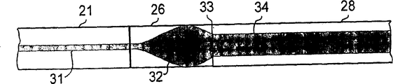
Fig. 3 shows above-described this structure.Label 21 sign pumping combiner sections, label 23 id signal fibers, label 26 sign gradient-index lens, and the importation of label 28 sign gain section.For the sake of clarity, three elements illustrate with released state.When being assembled into last device, these elements are fused to together or join to together, adopt the optical fiber fusion interconnection technique of standard.In described preferred situation, element 26 is one section optical fiber that has with element 21 and 28 identical covering outer dias.
Fig. 4 is illustrated in the mode pattern of the light beam of propagating on each section 21,26 and 28 that is coupled together.Shown in the label 31 is the light beam that has reduced area that comes out from pumping combiner section.In the time of on being coupled to gradient-index lens element 26, the mould field is expansion controllably as shown in the figure.The selection of the length of gradient-index lens makes the output terminal of lens, that is, interface 33, be created in beam spot size and light beam phase place curvature substantially with the individual features coupling of gain section 28.Can make light beam enter gain section like this and have a mould field 34 of suitably expanding and collimating, and not have insertion loss basically.
Gradient-index lens can comprise one section optical fiber with monodrome parabolic refractive index gradient.Also can be by one section plastics or other transparent body with this characteristic.Be very suitable for being used for gradient index fibre of the present invention and comprise so-called square-law medium (square lawmedium).The radially correlativity of refractive index is in the square-law medium:
n(r)=n
0[1-g
2r
2]
0.5
Wherein, n
0Be the refractive index on optical axis, the focusing parameter of g for providing by following formula:
g=(2Δ)
0.5/a
Δ (=[n wherein
0-n (a)]/n (a)) be at central core (n
0) and covering between refringence (being expressed as mark), a is the radius of core.Other details of Gaussian beam characteristic in element 26 is by the IEEE Trans.MicrowaveTheory Tech.Vol.MTT-30 in version in June nineteen eighty-two such as Kishimoto et al, No.6, pp.882-893, in provide, the document is incorporated herein by reference here.
A light beam with initial plane phase front is expanded or shunk fully to a square-law medium fully on a segment length, and this segment length is called as 1/4th pitches (pitch) length, and this length equals pi/2 g, and wherein g is the focusing parameter that above limits.
Adiabatic transducer of the present invention schematically illustrates in Fig. 5, and wherein, the pattern of mould field is by label 51 signs.In the gradient-index lens of typical case's 1/4th pitch lengths, length L
1Be 1/4th pitch lengths.Length L
2For example be selected in the position before of 52 signs are arranged in the light wave of being propagated, before the described light wave corresponding to being coupled to mould field required in the described gain section 28.In a preferred situation, the length of element 26 equals or is approximately equal to 1/4th pitch lengths.Yet, also in some situation, described size less than or greater than preferred length, in this situation, length L
2Become and compare L
1Shorter or longer (shown in example).
Although should be appreciated that suitable in the present invention 1/4th real pitch devices that use, other the lens not according to the square-law behavior also are operable.
In the example that index map 2-5 describes, what the core diameter in the gain section of described device was shown in pumping combiner section efferent office core diameter is approximately 17 times.This ratio is big more, then more need be according to adiabatic transducer of the present invention.Of the present inventionly mainly relate to following gain device, that is, representing the described ratio of the degree that do not match between the core diameter of efferent office of core diameter in the gain section and pumping combiner section to be at least 2 in this gain device, more typically greater than 10.In some situation, may be more favourable with the gain section bending to remove undesired mould.
Above describe and figure shown in pumping combiner section can think the end-pumping structure, it only is a kind of in several pumping configurations.For example, optical pumping and gain section can be combined, rather than the element that two different polyphones are provided with.In this case, pumping distributes along gain section, is similar to a side pumping device.The device of this general structure has open in U.S. Pat 4553238.
A device that has distribution pumping section has been shown in Fig. 6 and 7.Adaptively, label 61 signs is the end view of fiber gain section.Pumping source is a multimode optical fiber 62, and this multimode optical fiber is arranged side by side with the gain fiber.When these fiber close enoughs, the energy that comes from the pumping fiber just passes to the gain fiber.This phenomenon has been known, and is used sometimes in photo-coupler.In Fig. 6, two fibers 61 and 62 side by side illustrate has common coating 63.The various ways of this pumping configuration is possible.Be similar to situation shown in the input end of pumping combiner shown in Figure 3, can use more than one pumping fiber in structure.Pumping fiber and gain fiber can carry out drawing-off and become a littler diameter, and can fuse together if desired.Yet, if they are assembled very near just enough.Fig. 7 shows the embodiment of distribution pumping among Fig. 6, shows input and output side.Be the representative section of gain section in Fig. 6, it is by label 63 signs.The approximate length that is proportional to gain section of amount of gain in this device, that is, fiber institute is along the length that is coupled.Label 61 sign gain fibers, it is carrying light signal or mode of laser.Label 62 sign pumping fibers.Mode field diameter is by circle 65,66 representatives.Adiabatic transducer of the present invention is by label 67 and 68 signs.In this device, show two transducers.The transducer 67 that is positioned at input side expands the mould field with the mould field of coupling in gain section.Second transducer 68 is used in the opposite direction the mould field pattern be turned back to original-shape, or the territory, mould place of different size (input vs output) then reduces the mould field pattern if desired.As shown by arrows, pump light can be propagated on any direction.
Here describing with reference to a gain section or gain device is that intention is described the fiber device that strengthens the power that is arranged in the light wave that optical fiber propagates.Having been mixed up a kind of rare earth element in these optical fiber, typically be erbium, perhaps mixed up rare earth element er, Nd, Yb, Sm, La, Ce, Pr, Pm, Gd, Tb, Dy, Ho, Tm, the composition of Lu. other dopant such as Al, P also often exist.
For those skilled in the art, can carry out various other variations to the present invention.All are under concrete instruction of the present invention and depend on principle that prior art instructed and equivalent and the growth that obtains all should be considered to be considered in the claim protection domain of the present invention.
Claims (9)
1. gain of light device comprises:
A. an input optical fibre, this input optical fibre has the first mode field diameter D
1,
B. the adiabatic transformer section of an optical fiber, the adiabatic transformer section of this optical fiber comprises a gradient index fibre,
C. a fiber gain section, this fiber gain section comprises that one has the second mode field diameter D
2Optical fiber, the second mould field D wherein
2Greater than the first mode field diameter D
110 times and
D. be used for device that described fiber gain section is carried out optical pumping, the gradient of the refractive index that wherein said gradient index fibre has makes the light beam by described gradient index fibre have from D
1Expand to D
2The mould field, described input optical fibre is connected to described gradient index fibre by fusion, thereby and the described gradient index fibre optical fiber that is connected to described fiber gain section by fusion form a whole vitreum that comprises described input optical fibre, the adiabatic transformer section of described optical fiber and described fiber gain section.
2. device as claimed in claim 1 is characterized in that, the described device that is used for gain section is carried out optical pumping is an end-pumping.
3. device as claimed in claim 1 is characterized in that, the described device that is used for gain section is carried out optical pumping is a side pumping.
4. device as claimed in claim 2, it is characterized in that, the described device that is used for gain section is carried out optical pumping is the pumping combiner section with an importation and an output, and described importation comprises that a principal fiber that is surrounded by one or more pumping fiber constitutes an assembly.
5. device as claimed in claim 3 is characterized in that, the described device that is used for gain section is carried out optical pumping is a distribution pumping section, and this distribution pumping section comprises a gain fiber that is surrounded by one or more pumping fiber.
6. device as claimed in claim 5 is characterized in that, described gradient index fibre section comprises that one has 1/4th pitch length L
11/4th pitch square-law media.
7. device as claimed in claim 6 is characterized in that, the length of described gradient index fibre section is L
2, L wherein
2Less than L
1
8. device as claimed in claim 7 is characterized in that, the length of described gradient index fibre section is L
2, L wherein
2Greater than L
1
9. gain of light device as claimed in claim 1, wherein, the gain fiber is bent to reduce unwanted high-order mode.
Applications Claiming Priority (2)
| Application Number | Priority Date | Filing Date | Title |
|---|---|---|---|
| US10/461,133 US6970624B2 (en) | 2003-06-13 | 2003-06-13 | Cladding pumped optical fiber gain devices |
| US10/461,133 | 2003-06-13 |
Publications (2)
| Publication Number | Publication Date |
|---|---|
| CN1617003A CN1617003A (en) | 2005-05-18 |
| CN100397124C true CN100397124C (en) | 2008-06-25 |
Family
ID=33299769
Family Applications (1)
| Application Number | Title | Priority Date | Filing Date |
|---|---|---|---|
| CNB2004100490740A Active CN100397124C (en) | 2003-06-13 | 2004-06-11 | Cladding pumped optical fiber gain device |
Country Status (4)
| Country | Link |
|---|---|
| US (1) | US6970624B2 (en) |
| EP (2) | EP2086069B1 (en) |
| JP (1) | JP3987840B2 (en) |
| CN (1) | CN100397124C (en) |
Families Citing this family (42)
| Publication number | Priority date | Publication date | Assignee | Title |
|---|---|---|---|---|
| US7046875B2 (en) * | 2003-10-29 | 2006-05-16 | Itf Technologies Optiques Inc. | Optical coupler comprising multimode fibers and method of making the same |
| US7016573B2 (en) * | 2003-11-13 | 2006-03-21 | Imra America, Inc. | Optical fiber pump multiplexer |
| EP1811616B1 (en) * | 2005-12-16 | 2017-01-04 | OFS Fitel, LLC | Rare-earth-doped, large-mode-area, multimode, hybrid optical fibers and devices using the same |
| JP5173137B2 (en) * | 2006-01-27 | 2013-03-27 | 株式会社フジクラ | Double clad fiber, coupling structure, fiber amplifier and fiber laser |
| US7532792B2 (en) * | 2006-08-28 | 2009-05-12 | Crystal Fibre A/S | Optical coupler, a method of its fabrication and use |
| GB2439345A (en) * | 2006-06-23 | 2007-12-27 | Gsi Group Ltd | Annular tapered fibre coupler for cladding pumping of an optical fibre |
| US7340138B1 (en) * | 2007-01-25 | 2008-03-04 | Furukawa Electric North America, Inc. | Optical fiber devices and methods for interconnecting dissimilar fibers |
| US7916386B2 (en) * | 2007-01-26 | 2011-03-29 | Ofs Fitel, Llc | High power optical apparatus employing large-mode-area, multimode, gain-producing optical fibers |
| US20080267560A1 (en) * | 2007-04-30 | 2008-10-30 | Digiovanni David John | Mode-field resizing in optical fibers |
| US7844146B2 (en) * | 2008-04-30 | 2010-11-30 | Ofs Fitel, Llc | All-fiber module for femtosecond pulse compression and supercontinuum generation |
| US9063289B1 (en) * | 2008-06-30 | 2015-06-23 | Nlight Photonics Corporation | Multimode fiber combiners |
| US8873134B2 (en) | 2008-08-21 | 2014-10-28 | Nlight Photonics Corporation | Hybrid laser amplifier system including active taper |
| US9285541B2 (en) | 2008-08-21 | 2016-03-15 | Nlight Photonics Corporation | UV-green converting fiber laser using active tapers |
| US9158070B2 (en) | 2008-08-21 | 2015-10-13 | Nlight Photonics Corporation | Active tapers with reduced nonlinearity |
| DE102008053728B4 (en) * | 2008-10-29 | 2015-02-26 | Trumpf Laser Gmbh | Optical fiber arrangement |
| JP2010199563A (en) * | 2009-01-27 | 2010-09-09 | Fujikura Ltd | Optical amplifier and resonator |
| US8218928B2 (en) | 2009-04-23 | 2012-07-10 | Ofs Fitel, Llc | Spatial filtering of higher order modes in multimode fibers |
| US9494738B1 (en) | 2009-05-28 | 2016-11-15 | Nlight, Inc. | Single mode fiber combiners |
| US8514485B2 (en) * | 2009-08-07 | 2013-08-20 | Northrop Grumman Systems Corporation | Passive all-fiber integrated high power coherent beam combination |
| US8184363B2 (en) * | 2009-08-07 | 2012-05-22 | Northrop Grumman Systems Corporation | All-fiber integrated high power coherent beam combination |
| US8184361B2 (en) * | 2009-08-07 | 2012-05-22 | Northrop Grumman Systems Corporation | Integrated spectral and all-fiber coherent beam combination |
| JP2011124460A (en) * | 2009-12-14 | 2011-06-23 | Fujikura Ltd | Optical fiber emission circuit and fiber laser |
| US9484706B1 (en) | 2012-06-12 | 2016-11-01 | Nlight, Inc. | Tapered core fiber manufacturing methods |
| WO2014011846A2 (en) * | 2012-07-12 | 2014-01-16 | The Government Of The United States Of America, As Represented By The Secretary Of The Navy | Wavelength and power scalable waveguiding-based infrared laser system |
| US9366810B2 (en) | 2012-08-29 | 2016-06-14 | Ofs Fitel, Llc | Double-clad, gain-producing fibers with increased cladding absoroption while maintaining single-mode operation |
| US9366806B2 (en) | 2012-08-29 | 2016-06-14 | Ofs Fitel, Llc | Gain-producing fibers with increased cladding absorption while maintaining single-mode operation |
| WO2014105756A1 (en) | 2012-12-31 | 2014-07-03 | Nlight Photonics Corporation | Spatially stable high brightness fiber |
| WO2014105757A1 (en) | 2012-12-31 | 2014-07-03 | Nlight Photonics Corporation | All fiber low dynamic pointing high power lma fiber amplifier |
| US9214781B2 (en) | 2013-11-21 | 2015-12-15 | Lockheed Martin Corporation | Fiber amplifier system for suppression of modal instabilities and method |
| CN103984059B (en) * | 2014-05-26 | 2016-05-18 | 山东海富光子科技股份有限公司 | A kind of (N+1) × 1 optical fiber end surface pump combiner based on fiber optical corrosive |
| US10069271B2 (en) | 2014-06-02 | 2018-09-04 | Nlight, Inc. | Scalable high power fiber laser |
| US9837783B2 (en) | 2015-01-26 | 2017-12-05 | Nlight, Inc. | High-power, single-mode fiber sources |
| US10050404B2 (en) * | 2015-03-26 | 2018-08-14 | Nlight, Inc. | Fiber source with cascaded gain stages and/or multimode delivery fiber with low splice loss |
| WO2017008022A1 (en) | 2015-07-08 | 2017-01-12 | Nlight, Inc. | Fiber with depressed central index for increased beam parameter product |
| WO2018063452A1 (en) | 2016-09-29 | 2018-04-05 | Nlight, Inc. | Adjustable beam characteristics |
| US10673199B2 (en) | 2016-09-29 | 2020-06-02 | Nlight, Inc. | Fiber-based saturable absorber |
| US10673198B2 (en) | 2016-09-29 | 2020-06-02 | Nlight, Inc. | Fiber-coupled laser with time varying beam characteristics |
| US10730785B2 (en) | 2016-09-29 | 2020-08-04 | Nlight, Inc. | Optical fiber bending mechanisms |
| US10673197B2 (en) | 2016-09-29 | 2020-06-02 | Nlight, Inc. | Fiber-based optical modulator |
| CN107561635A (en) * | 2017-10-13 | 2018-01-09 | 中国工程物理研究院激光聚变研究中心 | Gradual change absorption coefficient gain fibre and optical system |
| KR102609262B1 (en) | 2018-05-14 | 2023-12-04 | 시반 어드밴스드 테크놀러지스 엘티디. | Laser beams methods and systems |
| CN108879312B (en) * | 2018-06-20 | 2019-09-17 | 上海卫星工程研究所 | Solar-pumped optical-fiber laser amplification system |
Citations (7)
| Publication number | Priority date | Publication date | Assignee | Title |
|---|---|---|---|---|
| US4701011A (en) * | 1985-01-15 | 1987-10-20 | American Telephone And Telegraph Company, At&T Bell Laboratories | Multimode fiber-lens optical coupler |
| JPH057037A (en) * | 1991-06-27 | 1993-01-14 | Mitsubishi Cable Ind Ltd | Optical fiber amplifier |
| US5864644A (en) * | 1997-07-21 | 1999-01-26 | Lucent Technologies Inc. | Tapered fiber bundles for coupling light into and out of cladding-pumped fiber devices |
| US6043929A (en) * | 1998-03-16 | 2000-03-28 | Lucent Technologies, Inc. | Adiabatic waveguide amplifier |
| JP2002006169A (en) * | 2000-06-27 | 2002-01-09 | Central Glass Co Ltd | Optical amplification fiber module |
| US6434302B1 (en) * | 1998-03-04 | 2002-08-13 | Jds Uniphase Corporation | Optical couplers for multimode fibers |
| US6433927B1 (en) * | 1999-12-02 | 2002-08-13 | Jds Uniphase Inc. | Low cost amplifier using bulk optics |
Family Cites Families (13)
| Publication number | Priority date | Publication date | Assignee | Title |
|---|---|---|---|---|
| US4553238A (en) * | 1983-09-30 | 1985-11-12 | The Board Of Trustees Of The Leland Stanford University | Fiber optic amplifier |
| US4737004A (en) * | 1985-10-03 | 1988-04-12 | American Telephone And Telegraph Company, At&T Bell Laboratories | Expanded end optical fiber and associated coupling arrangements |
| US5418880A (en) | 1994-07-29 | 1995-05-23 | Polaroid Corporation | High-power optical fiber amplifier or laser device |
| JP3298799B2 (en) | 1995-11-22 | 2002-07-08 | ルーセント テクノロジーズ インコーポレイテッド | Cladding pump fiber and its manufacturing method |
| US5892615A (en) * | 1997-03-17 | 1999-04-06 | Sdl, Inc. | Output power enhancement in optical fiber lasers |
| US6014389A (en) * | 1997-03-24 | 2000-01-11 | The United States Of America As Represented By The Secretary Of The Air Force | Fiber-based continuous wave blue laser source |
| US6606446B1 (en) * | 1997-05-19 | 2003-08-12 | Jds Uniphase Corporation | Miniature variable attenuator |
| US5937134A (en) | 1997-08-07 | 1999-08-10 | Lucent Technologies Inc. | Cladding pumped fiber lasers |
| KR100276968B1 (en) * | 1998-07-11 | 2001-01-15 | 윤덕용 | Optical interconnection structure for enlarging alignment tolerance |
| US6597711B2 (en) * | 1998-12-04 | 2003-07-22 | Cidra Corporation | Bragg grating-based laser |
| US6411757B1 (en) * | 2000-02-14 | 2002-06-25 | Agere Systems Guardian Corp. | Article comprising a waveguide structure with improved pump utilization |
| EP1260841B1 (en) * | 2001-05-19 | 2007-07-11 | Lucent Technologies Inc. | GRIN fiber lenses |
| CN1332228C (en) * | 2001-06-15 | 2007-08-15 | 康宁股份有限公司 | Tapered lensed fiber for focusing and condenser applications |
-
2003
- 2003-06-13 US US10/461,133 patent/US6970624B2/en not_active Expired - Lifetime
-
2004
- 2004-05-07 EP EP09005772A patent/EP2086069B1/en active Active
- 2004-05-07 EP EP04010943A patent/EP1487070A1/en not_active Withdrawn
- 2004-06-11 CN CNB2004100490740A patent/CN100397124C/en active Active
- 2004-06-11 JP JP2004173272A patent/JP3987840B2/en active Active
Patent Citations (7)
| Publication number | Priority date | Publication date | Assignee | Title |
|---|---|---|---|---|
| US4701011A (en) * | 1985-01-15 | 1987-10-20 | American Telephone And Telegraph Company, At&T Bell Laboratories | Multimode fiber-lens optical coupler |
| JPH057037A (en) * | 1991-06-27 | 1993-01-14 | Mitsubishi Cable Ind Ltd | Optical fiber amplifier |
| US5864644A (en) * | 1997-07-21 | 1999-01-26 | Lucent Technologies Inc. | Tapered fiber bundles for coupling light into and out of cladding-pumped fiber devices |
| US6434302B1 (en) * | 1998-03-04 | 2002-08-13 | Jds Uniphase Corporation | Optical couplers for multimode fibers |
| US6043929A (en) * | 1998-03-16 | 2000-03-28 | Lucent Technologies, Inc. | Adiabatic waveguide amplifier |
| US6433927B1 (en) * | 1999-12-02 | 2002-08-13 | Jds Uniphase Inc. | Low cost amplifier using bulk optics |
| JP2002006169A (en) * | 2000-06-27 | 2002-01-09 | Central Glass Co Ltd | Optical amplification fiber module |
Also Published As
| Publication number | Publication date |
|---|---|
| US6970624B2 (en) | 2005-11-29 |
| EP2086069A2 (en) | 2009-08-05 |
| JP2005005717A (en) | 2005-01-06 |
| CN1617003A (en) | 2005-05-18 |
| EP2086069B1 (en) | 2013-01-16 |
| JP3987840B2 (en) | 2007-10-10 |
| US20040252946A1 (en) | 2004-12-16 |
| EP1487070A1 (en) | 2004-12-15 |
| EP2086069A3 (en) | 2009-08-19 |
Similar Documents
| Publication | Publication Date | Title |
|---|---|---|
| CN100397124C (en) | Cladding pumped optical fiber gain device | |
| EP1060423B1 (en) | Optical couplers for multimode fibers | |
| CN101288211B (en) | Optical fibre laser | |
| US7046432B2 (en) | Optical fiber coupling arrangement | |
| US9946014B2 (en) | Techniques and devices for low-loss coupling to a multicore fiber | |
| US6434295B1 (en) | Side coupled pumping of double clad fiber gain media | |
| CN101688944B (en) | Pumping under the high-order mode substantially identical with signal mode | |
| CN103999302B (en) | High power single mode fiber pump laser system at 980 nm. | |
| US8085464B2 (en) | Multi-clad optical fibre amplifier with optimized pumping | |
| AU642698B2 (en) | Optical amplifier having a single-mode curved active fibre | |
| US20050207455A1 (en) | Method and apparatus for efficient coupling of pump light into fiber amplifiers | |
| AU2804701A (en) | Optical fiber for optical amplifier, optical fiber amplifier and optical fiber laser | |
| JPH11136193A (en) | Twin coupler having mode scrambling for multimode pumping of light amplifier | |
| EP2625753B1 (en) | High power neodymium fiber lasers and amplifiers | |
| US9768581B2 (en) | Pump and signal combiner for high numerical aperture use | |
| US9322993B1 (en) | All pump combiner with cladless inputs | |
| JP5173137B2 (en) | Double clad fiber, coupling structure, fiber amplifier and fiber laser | |
| US9362709B1 (en) | Optical fiber laser architecture with partitioned pump and signal coupling | |
| US9595803B2 (en) | Fat-fiber adapter for pump use |
Legal Events
| Date | Code | Title | Description |
|---|---|---|---|
| C06 | Publication | ||
| PB01 | Publication | ||
| C10 | Entry into substantive examination | ||
| SE01 | Entry into force of request for substantive examination | ||
| C14 | Grant of patent or utility model | ||
| GR01 | Patent grant |