CN100413458C - Insert support system - Google Patents
Insert support system Download PDFInfo
- Publication number
- CN100413458C CN100413458C CNB200480032338XA CN200480032338A CN100413458C CN 100413458 C CN100413458 C CN 100413458C CN B200480032338X A CNB200480032338X A CN B200480032338XA CN 200480032338 A CN200480032338 A CN 200480032338A CN 100413458 C CN100413458 C CN 100413458C
- Authority
- CN
- China
- Prior art keywords
- path
- image
- unit
- vbs
- region
- Prior art date
- Legal status (The legal status is an assumption and is not a legal conclusion. Google has not performed a legal analysis and makes no representation as to the accuracy of the status listed.)
- Active
Links
Images


Classifications
-
- A—HUMAN NECESSITIES
- A61—MEDICAL OR VETERINARY SCIENCE; HYGIENE
- A61B—DIAGNOSIS; SURGERY; IDENTIFICATION
- A61B1/00—Instruments for performing medical examinations of the interior of cavities or tubes of the body by visual or photographical inspection, e.g. endoscopes; Illuminating arrangements therefor
- A61B1/00002—Operational features of endoscopes
- A61B1/00004—Operational features of endoscopes characterised by electronic signal processing
- A61B1/00009—Operational features of endoscopes characterised by electronic signal processing of image signals during a use of endoscope
-
- A—HUMAN NECESSITIES
- A61—MEDICAL OR VETERINARY SCIENCE; HYGIENE
- A61B—DIAGNOSIS; SURGERY; IDENTIFICATION
- A61B34/00—Computer-aided surgery; Manipulators or robots specially adapted for use in surgery
- A61B34/10—Computer-aided planning, simulation or modelling of surgical operations
-
- A—HUMAN NECESSITIES
- A61—MEDICAL OR VETERINARY SCIENCE; HYGIENE
- A61B—DIAGNOSIS; SURGERY; IDENTIFICATION
- A61B10/00—Other methods or instruments for diagnosis, e.g. instruments for taking a cell sample, for biopsy, for vaccination diagnosis; Sex determination; Ovulation-period determination; Throat striking implements
- A61B10/02—Instruments for taking cell samples or for biopsy
-
- A—HUMAN NECESSITIES
- A61—MEDICAL OR VETERINARY SCIENCE; HYGIENE
- A61B—DIAGNOSIS; SURGERY; IDENTIFICATION
- A61B34/00—Computer-aided surgery; Manipulators or robots specially adapted for use in surgery
- A61B34/10—Computer-aided planning, simulation or modelling of surgical operations
- A61B2034/101—Computer-aided simulation of surgical operations
- A61B2034/105—Modelling of the patient, e.g. for ligaments or bones
-
- A—HUMAN NECESSITIES
- A61—MEDICAL OR VETERINARY SCIENCE; HYGIENE
- A61B—DIAGNOSIS; SURGERY; IDENTIFICATION
- A61B34/00—Computer-aided surgery; Manipulators or robots specially adapted for use in surgery
- A61B34/20—Surgical navigation systems; Devices for tracking or guiding surgical instruments, e.g. for frameless stereotaxis
- A61B2034/2046—Tracking techniques
- A61B2034/2065—Tracking using image or pattern recognition
-
- A—HUMAN NECESSITIES
- A61—MEDICAL OR VETERINARY SCIENCE; HYGIENE
- A61B—DIAGNOSIS; SURGERY; IDENTIFICATION
- A61B34/00—Computer-aided surgery; Manipulators or robots specially adapted for use in surgery
- A61B34/30—Surgical robots
- A61B2034/301—Surgical robots for introducing or steering flexible instruments inserted into the body, e.g. catheters or endoscopes
-
- A—HUMAN NECESSITIES
- A61—MEDICAL OR VETERINARY SCIENCE; HYGIENE
- A61B—DIAGNOSIS; SURGERY; IDENTIFICATION
- A61B34/00—Computer-aided surgery; Manipulators or robots specially adapted for use in surgery
- A61B34/25—User interfaces for surgical systems
Abstract
With a bronchial tube insertion support system according to the present invention, a route setting unit comprises a route starting-point setting function for setting the insertion starting-point of a bronchial tube, a region-of-interest setting function for setting a region of interest serving as the insertion end-point of the bronchial tube, a route extracting function for extracting an insertion route from an insertion start point to an insertion end point, and a route verifying function for performing verification of the extracted insertion route. According to these functions, of multiple insertion routes, the most appropriate insertion route when performing insertion support is determined.
Description
Technical field
The present invention relates to support the insertion back-up system of the insertion of endoscope.
Background technology
Carry out diagnosis in recent years widely based on image, for example, utilize X ray CT (ComputedTomography, computer tomography) device to wait the layer image of taking subject, thereby in subject, obtain 3 d image data, use this 3 d image data to carry out the diagnosis of target site.
In the CT device, carry subject continuously by rotational x-ray irradiation/detection continuously and on the axon direction, can carry out spiral helicine continuous sweep (helical scanning: helical scan), make 3-D view to the 3D region of subject according to the layer image of the serial section of 3D region.
The bronchial 3-D view that lung is arranged as one of this 3-D view.Bronchial 3-D view for example is used for grasping the position of the abnormal portion that is suspect to be pulmonary carcinoma etc. three-dimensionally.And, in order to confirm abnormal portion, insert bronchus endoscope and stretch out biopsy needle or biopsy forceps etc. from terminal part by biopsy, gather the sample (sample) of tissue.
In as bronchus, having the ramose body in a plurality of stages in the pipeline, the position of abnormal portion is during near ramose tip, be difficult to make the end of endoscope accurately to arrive target site at short notice, therefore following device has for example been proposed: the three-dimensional image that makes described tested intravital pipeline according to the view data of the 3D region of subject in TOHKEMY 2000-135215 communique etc., on described three-dimensional image, obtain the path that arrives impact point along described pipeline, make in the described pipeline in described path virtual according to described view data and to peep picture, show and describedly peep picture in virtual, thereby bronchus endoscope target goal position.
But, generally there is autgmentability in biological tissue as target site, even so biopsy position when specifying biopsy, can not determine to arrive the insertion path of this biopsy position uniquely, and may set a plurality of insertions path, but in conventional device, the best that existence can not be determined to insert from a plurality of insertions path when supporting is inserted path problems.
The present invention In view of the foregoing proposes, and its purpose is, the insertion back-up system that can verify the best insertion path of inserting when supporting in a plurality of insertions path is provided.
Summary of the invention
Insertion back-up system of the present invention constitutes to have: the virtual image generation unit, and it generates the virtual image on described tested intravital body cavity road according to the view data of the 3D region of subject; Path initial point setup unit, it sets the initial point in the insertion path on the described tested intravital body cavity of endoscopy reaching road; The region-of-interest setup unit, it sets the zone at described tested intravital concern position; The path extraction unit, it extracts a plurality of described insertion path in the zone from described initial point to described concern position; And the path validation unit, a plurality of described insertion path that its checking is extracted by described path extraction unit.
Insertion back-up system of the present invention has the effect that can verify the best insertion path of inserting when supporting from a plurality of insertions path.
Description of drawings
Fig. 1 is the structure chart that the bronchus of expression embodiments of the invention 1 is inserted the structure of back-up system.
Fig. 2 is the block diagram of functional structure of the path setting portion of presentation graphs 1.
Fig. 3 is the flow chart that the flow process handled is prepared in insertion support that the insertion supportive device of expression by Fig. 1 carries out.
Fig. 4 is the 1st figure that is illustrated in unfolded path setting picture in the processing of Fig. 3.
Fig. 5 is the 2nd figure that is illustrated in unfolded path setting picture in the processing of Fig. 3.
Fig. 6 is the 3rd figure that is illustrated in unfolded path setting picture in the processing of Fig. 3.
Fig. 7 is the 4th figure that is illustrated in unfolded path setting picture in the processing of Fig. 3.
Fig. 8 is the 5th figure that is illustrated in unfolded path setting picture in the processing of Fig. 3.
Fig. 9 is the flow chart of the flow process handled of the path setting of presentation graphs 3.
Figure 10 is the 1st figure of the processing of key diagram 9.
Figure 11 is the 2nd figure of the processing of key diagram 9.
Figure 12 is the 1st figure that is illustrated in unfolded path setting picture in the processing of Fig. 9.
Figure 13 is the 3rd figure of the processing of key diagram 9.
Figure 14 is the 2nd figure that is illustrated in unfolded path setting picture in the processing of Fig. 9.
Figure 15 is the 4th figure of the processing of key diagram 9.
Figure 16 is the 3rd figure that is illustrated in unfolded path setting picture in the processing of Fig. 9.
The figure of the path validation window of Figure 17 MPR image that to be expression generated based on the path validation function of the path setting portion of Fig. 2.
Figure 18 is the 1st figure of effect of the path validation window of explanation Figure 17.
Figure 19 is the 2nd figure of effect of the path validation window of explanation Figure 17.
Figure 20 is the 3rd figure of effect of the path validation window of explanation Figure 17.
Figure 21 is the 4th figure of effect of the path validation window of explanation Figure 17.
Figure 22 is the 5th figure of effect of the path validation window of explanation Figure 17.
Figure 23 is the 6th figure of effect of the path validation window of explanation Figure 17.
Figure 24 is the 7th figure of effect of the path validation window of explanation Figure 17.
Figure 25 is the 8th figure of effect of the path validation window of explanation Figure 17.
Figure 26 is the 9th figure of effect of the path validation window of explanation Figure 17.
Figure 27 is the 1st figure of the VBS display box of explanation Figure 26.
Figure 28 is the 2nd figure of the VBS display box of explanation Figure 26.
Figure 29 is the 3rd figure of the VBS display box of explanation Figure 26.
Figure 30 is the figure of variation of the VBS display box of explanation Figure 26.
The figure of the path validation window of Figure 31 graph thinning model image that to be expression generated based on the path validation function of the path setting portion of Fig. 2.
Figure 32 is the figure of the graph thinning model image of explanation Figure 31.
Figure 33 is the 1st figure of effect of the path validation window of explanation Figure 31.
Figure 34 is the 2nd figure of effect of the path validation window of explanation Figure 31.
Figure 35 is the 3rd figure of effect of the path validation window of explanation Figure 31.
Figure 36 is the 4th figure of effect of the path validation window of explanation Figure 31.
Figure 37 is the 5th figure of effect of the path validation window of explanation Figure 31.
Figure 38 is the 6th figure of effect of the path validation window of explanation Figure 31.
Figure 39 is illustrated in the figure that picture is supported in unfolded insertion in the processing of Fig. 9.
Figure 40 is the flow chart of expression based on the flow process of the path setting simulation process of the path validation function of embodiments of the invention 2.
Figure 41 is the 1st figure of the path setting simulation process of explanation Figure 40.
Figure 42 is the 2nd figure of the path setting simulation process of explanation Figure 40.
Figure 43 is the 3rd figure of the path setting simulation process of explanation Figure 40.
Figure 44 is the 4th figure of the path setting simulation process of explanation Figure 40.
The specific embodiment
Below, with reference to the description of drawings embodiments of the invention.
(embodiment 1)
As shown in Figure 1, the bronchus of present embodiment insertion back-up system 1 is made of bronchus endoscope apparatus 3 and insertion supportive device 5.
Inserting supportive device 5 generates according to the CT view data and peeps picture (below be expressed as the VBS image) in bronchus inside virtual, and endoscopic images that will obtain by bronchus endoscope apparatus 3 (below be expressed as real time imaging) and VBS image are synthetic, be presented on the monitor 6, carry out bronchus endoscope apparatus 3 to bronchial insertion support.
And, though it is not shown, but bronchus endoscope apparatus 3 is by the bronchoscope with image unit, provide the light source of illumination light and camera control unit of carrying out signal processing from bronchoscopic image pickup signal etc. is constituted to bronchoscope, bronchoscope is inserted in the intravital bronchus of patient, bronchus inside is taken, destination organization to the bronchus end carries out biopsy, and real time imaging and VBS image is synthetic and be presented on the monitor 7.
Monitor 7 is provided with the input part 8 that is made of touch screen, can simultaneously insert the operation one side and easily operate the input part 8 that is made of touch screen.
Insert supportive device 5 by constituting with the lower part: the CT view data is taken into portion 11, it is by for example MO (Magnetic Optical disk, magneto-optic disk) device or DVD (Digital VersatileDisk, digital versatile disc) device waits the storage medium of mobile model, is taken into the 3 d image data by the not shown known CT device generation of the x-ray tomography picture of taking the patient; CT image data storage portion 12, its storage is taken into the CT view data that portion 11 is taken into by the CT view data; MPR image production part 13, it generates MPR image (multibreak reconstructed image: crown position picture, axis location image, sagittal plain picture) according to the CT view data that is stored in the CT image data storage portion 12; Path setting portion 14, its generation has the path setting picture described later of the MPR image that is generated by the MPR image production part, sets bronchus endoscope apparatus 3 and arrives bronchial support path (following brief note is the path); VBS image production part 15 as the virtual image generation unit, it is according to the CT view data that is stored in the CT image data storage portion 12, with the frame is the successive VBS image VBS image storage part 16 that unit generates the path of being set by path setting portion 14, the VBS image that its storage is generated by VBS image production part 15; Image processing part 17, its input generates by the insertion described later of real time imaging, VBS image and a plurality of breviary VBS image construction and supports picture from the image pickup signal of bronchus endoscope apparatus 3 with from the input signal of input part 8; Pictorial display control part 18, it shows path setting picture that is generated by path setting portion 14 and the insertion support picture that is generated by image processing part 17 on monitor 6; And input equipment 19, it is made of keyboard and the indicating equipment to path setting portion 14 input set informations.
In addition, CT image data storage portion 12 and VBS image storage part 16 also can constitute by a hard disk, and MPR image production part 13, path setting portion 14, VBS image production part 15 and image processing part 17 can be made of an arithmetic processing circuit.And, the CT view data is taken into portion's 11 storage mediums by mobile models such as MO or DVD and is taken into the CT view data, but when the internal server of CT device or preservation CT view data is connected on the internal lan, also can constitute the CT view data by the interface circuit that can connect this internal lan and be taken into portion 11, be taken into the CT view data by internal lan.
As shown in Figure 2, path setting portion 14 constitutes to have: as the path initial point set-up function 14a of path initial point setup unit, it sets the insertion initial point that bronchus is inserted; As the region-of-interest set-up function 14b of region-of-interest setup unit, it sets the region-of-interest of the insertion terminal point that inserts as bronchus; As the unitary path extraction function of path extraction 14c, it extracts from inserting initial point to the insertion path of inserting terminal point; And as the unitary path validation function of path validation 14d, it carries out the checking in the insertion path of being extracted.Concrete condition about these functions will be narrated in the back.
The effect of the present embodiment that constitutes like this is described.
As shown in Figure 3, utilizing before bronchus endoscope apparatus 3 observes/dispose, insert supportive device 5 and in step S1, be taken into the CT view data that portion 11 is taken into the patient who is generated by the CT device by the CT view data, in step S2 the CT image data storage that is taken in CT image data storage portion 12.
In step S3, on monitor 6, show path setting picture 21 shown in Figure 4 by path setting portion 14, select patient information in the patient information tab picture 22 on path setting picture 21.By this selection, in step S4, generate selected patient for example by 3 multibreak different reconstructed images constitute as the crown position of MPR image as 23a, axle bit image 23b, sagittal plain as 23c (following also brief note is MPR image 23), in step S5, on path setting picture 21, show should crown as 23a, axis location image 23b, sagittal plain as 23c.In path setting picture 21, be provided with the VBS image display area 23d that shows the VBS image.
In addition, the selection of the patient information in the patient information tab picture 22 is undertaken by the patient ID that utilizes input equipment 19 input identification patients.
Then, in step S6, during by the path setting label 24 (with reference to Fig. 4) on the input equipment 19 selection path setting pictures 21, path setting label picture 25 shown in Figure 5 is presented on the path setting picture 21, carry out path setting described later and handle, set the path of bronchoscope in intrabronchial insertion support.
Having set when inserting the path of supporting, in step S7, be the successive VBS image that unit generates all paths that set with the frame by VBS image production part 15, in step S8, the VBS image that is generated is stored in the VBS image storage part 16.
By the processing of above-mentioned step S1~S8, finish use bronchoscope observe/passing through when disposing insert the preparation of the insertion support that supportive device 5 carries out.
Use Fig. 6~Fig. 9 that the path setting processing of above-mentioned steps S6 is described herein.
When having selected the route searching button in path setting picture 21, the path setting of beginning step S6 is handled.Specifically, path initial point set-up function 14a by path setting portion 14, on path setting picture 21, show the initial point input indication window 31 that impels input path initial point shown in Figure 6, using setting initial point 71 on the layer image of cursor 30 in MPR image 23 on the path setting picture 21.After setting initial point 71, also initial point 71 is set in the position in correspondence on other two layer images of MPR image 23, and the VBS image that shows initial point 71 in VBS image display area 23d, the setting that impels that demonstration is shown in Figure 7 on path setting picture 21 is imported indication window 32 as the biopsy regions of the biopsy regions 72 of path termination.
Then, utilize the region-of-interest set-up function 14b of path setting portion 14, on the path setting picture 21 of this Fig. 6, use and to draw two-dimensionally on any two layer images of cursor 30 in MPR image 23 and set biopsy regions 72 as region-of-interest.The quantity of the biopsy regions 72 that set this moment is not limited to one, and can specify a plurality ofly, figure 7 illustrates the state of specifying two biopsy regions 72a, 72b.
And, after the setting of biopsy regions 72 finishes, utilize the path extraction function 14c of path setting portion 14, show that on path setting picture 21 number of paths of the number of paths to be searched of each biopsy regions 72 of setting shown in Figure 8 is set window 33.By setting the number of paths to be searched of each biopsy regions 72, search out a plurality of introductory objects arrival biopsy regions 72 near the path.
That is, set initial point, biopsy regions 72 and searching route quantity by Fig. 6~Fig. 8 after, according to the processing of Fig. 9, utilize path extraction function 14c searching route.
That is, as shown in Figure 9, in step S11, detect the quantity of the biopsy regions 72 that sets, in step S12, read in searching route quantity n, in step S13, read in the position of initial point 71.
And, in step S14, extract the position of centre of gravity of biopsy regions 72, in step S15, the r of the radius of the ball of representing with the position of centre of gravity to be the center is made as initial value r0 after, in step S16, the region of search is appointed as in the ball inside of radius r.
Whether in step S17, judging has bronchus in the region of search, when bronchus is arranged, in step S18, determines with the path candidates of its position as terminal point.
After having determined path candidates, in step S19, judge whether determined path candidates is registered, when unregistered, in step S20, generate pathname based on the branch point title from the initial point to the terminal point, be registered as support path.
And, in step S21, judge that whether the number of paths of being registered is less than the number of paths n that reads in step S12.
In addition, in step S17, be judged as when determined path candidates has been registered when not having bronchus in the region of search, in step S19, when perhaps the number of paths of registering in step S21 is less than number of paths n, in step S22, r is made as r+ Δ r, enlarge the region of search, return step S16.
When registered number of paths reaches the number of paths n that reads in step S12, in step S23, judge whether to search for all biopsy regions that set, if searched for all biopsy regions then end process, when also having the biopsy regions of not search, in step S24, extract the position of centre of gravity of next biopsy regions, return step S15.
Specifically, as shown in figure 10, when having specified biopsy regions 72, extract the center of gravity 103 of biopsy regions 72 in the end of bronchus 101.
And, as shown in figure 11, the circle that is the center with this center of gravity 103 as region of search 104, region of search 104 expanded to make bronchus be positioned at region of search 104, the point that bronchus is positioned at region of search 104 at first as shown in figure 12, determines to connect the 1st path candidates 106 of initial point 71 and this terminal point 105 as terminal point 105, if the 1st path candidates 106 is still unregistered, then register as the 1st support path.The pathname of this moment is named according to the branch point title that will pass through.
After having determined the 1st support path, as shown in figure 13, increase is the radius of the region of search 104 at center with center of gravity 103, enlarge region of search 104, the point that bronchus is positioned at region of search 104 as shown in figure 14, determines to connect the 2nd path candidates 108 of initial point 71 and this terminal point 107 as terminal point 107 afterwards, if the 2nd path candidates 108 is still unregistered, then register as the 2nd support path.In Figure 14, the 2nd path candidates 108 is different with the 1st support path among Figure 12, so the 2nd path candidates 108 becomes the 2nd support path.The pathname of this moment is also named according to the branch point title that will pass through.
In the present embodiment, number of paths is 3, thus fully similarly, determined the 2nd support path after, as shown in figure 15, further increasing with center of gravity 103 is the radius of the region of search 104 at center, enlarges region of search 104, afterwards bronchus is positioned at the point of region of search 104 as terminal point 109, as shown in figure 16, determine to connect the 3rd path candidates 110 of initial point 71 and this terminal point 109,, then register as the 3rd support path if the 3rd path candidates 110 is still unregistered.In Figure 16, the 3rd path candidates 110 is different with the 1st and the 2nd support path, so the 3rd path candidates 110 becomes the 3rd support path.The pathname of this moment is also named according to the branch point title that will pass through.
Like this, can set the so much support path of specified number of paths.All biopsy regions 72 are carried out these handle, each biopsy regions 72 is set the specified so much support path of number of paths.
Below, the selection of the best support path in the path validation function 14d that utilizes path setting portion 14 a plurality of support paths that carry out, that set is described.
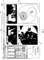
The path validation function 14d of path setting portion 14 shows path validation window 200 shown in Figure 17 behind input equipment 19 input validation commencing signals on monitor 6.Path validation window 200 is by constituting with the lower part: as the crown position of MPR image as 23a, axis location image 23b, sagittal plain as 23c; The VBS image display area 23d that shows the VBS image; The check box 201 of a plurality of support paths that appointment sets; And playback button 202, the VBS image that is presented among the VBS image display area 23d is moving image along the support path playback.Show a plurality of support paths that set as 23a, axis location image 23b, sagittal plain in as 23c in the crown position of this path validation window 200, shown in Figure 17 is 3.
And, for example shown in Figure 20, marked in the initial point position of the 1st support path under the state of pointer 210, when utilizing input equipment 19 to click playback button 202, pointer 210 moves to the final position along support path from the initial point position, the VBS image is presented among the VBS image display area 23d as moving image, and finally as shown in figure 21, the VBS image that is presented among the VBS image display area 23d becomes the VBS image that the final position is located.
In addition, marked in any position of the 1st support path under the situation of pointer 210, when clicking playback button 202, move to the final position from this position along support path, the VBS image is presented among the VBS image display area 23d as moving image, and finally still as shown in figure 21, the VBS image that is presented among the VBS image display area 23d becomes the VBS image that the final position is located.
Whether like this, can confirm the VBS image in the 1st support path, be the path that is suitable for supporting so can verify the 1st support path.
These processes also are applied to the 2nd support path and the 3rd support path, thereby can verify/select the path that is suitable for supporting most.
And, can a plurality of support paths of simultaneous verification in path validation window 200.Promptly, as shown in figure 22, when for example in check box 201, all selecting 3 support paths, mark pointer 210 as 23a, axis location image 23b, sagittal plain as the initial point position of the support path on the 23c in crown position, but because the initial point position of 3 support paths is identical, thus pointer 210 be shown as 1.At this moment, near pointer 210, indicate character data " 1 ", " 2 ", " 3 " that expression is the pointer of the 1st~the 3rd support path simultaneously.
And, in the path validation window 200 of this Figure 22, replace VBS image display area 23d and be provided with 3 VBS image display area 23d1, VBS image display area 23d2, VBS image display area 23d3 that are used to show the VBS image in each path.And, in VBS image display area 23d1, VBS image display area 23d2, VBS image display area 23d3, shown the VBS image at pointer 210 places on each path.In Figure 22, pointer 210 on each path is positioned at the initial point position, so it is all identical that the VBS image display area 23d2, the 3rd that the VBS image display area 23d1 that the 1st insertion path is used, the 2nd insertion path are used inserts the VBS image that shows among the VBS image display area 23d3 that uses in the path, shown the VBS image of initial point position.
And, under this state, for example click near the pointer 210 character datas " 3 " and when the 3rd inserts path movement, as shown in figure 23, insert the pointer 210 that marks the 3rd insertion path on the path the 3rd, and shown that in VBS image display area 23d3 the 3rd inserts the VBS image at pointer 210 places in path.At this moment, the VBS image that in VBS image display area 23d1, VBS image display area 23d2, still shows the initial point position.
The clicking operation of these character datas can be inserted on the path at each and carry out, by in inserting the path, carrying out this operation, in the VBS image display area corresponding, show the VBS image at pointer 210 places in this insertion path with the insertion path of having carried out operation.Follow the VBS image that moves of pointer 210 as described above like that as moving image and transition.
And, as shown in figure 24, when clicking playback button 202, each pointer 210 inserts path movement along all, the VBS image is presented at the 1st and inserts the VBS image display area 23d1 that the path is used as moving image, the 2nd inserts the VBS image display area 23d2 that the path is used, the 3rd inserts among the VBS image display area 23d3 that uses in the path, and finally as shown in figure 21, insert the VBS image display area 23d1 that the path is used the 1st, the 2nd inserts the VBS image display area 23d2 that the path is used, the 3rd inserts the VBS image that the VBS image that shows among the VBS image display area 23d3 that uses in the path becomes the place, final position.
As shown in figure 25, when being 4 in the insertion path, though shown that the 4th inserts the VBS image display area 23d4 that the path is used, the effect of this moment is identical with Figure 22~Figure 24.
And, be under the situation more than 5 or 5 inserting the path, when showing the VBS image simultaneously,, so as shown in figure 26, in path validation window 200, show VBS display box 220 because shown VBS image becomes too small.
As shown in figure 27, this VBS display box 220 is for example by constituting with the lower part: the check box 221 of specifying the support path arbitrarily in 6 support paths; And VBS image displaying part 222, it is made of the VBS image display area, and this VBS image display area shows that the support path of selecting by check box 221 is 4 or 4 the demonstration VBS image when following.For example, in check box 221, when having selected the 1st support path, the 3rd support path, the 4th support path, the 6th support path, mark the sequence number of support path in the upper left side of the VBS of VBS image displaying part 222 image display area, in this VBS image display area, shown the VBS image at pointer 210 places on each support path.The display packing of VBS image is identical with above-mentioned Figure 22~Figure 24.
And when for example having selected whole 6 support paths by check box 221, as Figure 28 and shown in Figure 29, show scroll bars 223 in VBS image displaying part 222.Though the VBS image display area that is presented in the VBS image displaying part 222 is limited to 4,, can confirm the VBS image of 6 VBS image display area successively by operation scroll bar 223.Figure 28 represents to show that the 1st~the 4th inserts the state of the VBS image on the path, and Figure 29 represents to show that the 3rd~the 6th inserts the state of the VBS image on the path.
In addition, replace check box 221 and as shown in figure 30, also can pass through input device 19, on VBS display box 220, show pop-up window 224, on pop-up window 224, select to insert the path, be limited to selection quantity below 4 or 4 this moment, thereby shown VBS size of images can be made as the size that can confirm.
And, in the path validation function 14d of the path setting portion 14 of present embodiment,, on monitor 6, show path validation window 200 shown in Figure 31 when input equipment 19 input paths show the change signals.
Hypomere in this 3D rendering viewing area 310 is provided with and makes anticlockwise button 311, the right rotation button 312 of graph thinning model image 301 around C axle rotation usefulness, and other is identical with Figure 17.
As shown in figure 33, when for example having selected the 1st to insert the path by check box 201, the initial point position on graph thinning model image 301 marks pointer 210, shows that in VBS image display area 23d the VBS image in path is inserted in the 1st of initial point position.
At this moment, when clicking anticlockwise button 311 or right rotation button 312, graph thinning model image 301 is around the axial left side of C or right rotation and corresponding time of click.The VBS image of VBS image display area 23d is the image that begins from fixed initial point, so graph thinning model image 301 during around the rotation of C axle, the VBS image synchronously rotates with this rotation.Thus, the VBS image is at random rotated in bronchus and confirm the VBS image.
And, as shown in figure 34, can make the pointer 210 on the graph thinning model image 301 move to the position of inserting arbitrarily on the path, this moment is as described above, the VBS image is as moving image and transition, and in VBS image display area 23d the VBS image in the insertion path at display pointer 210 places.
Equally, by clicking playback button 202, for example, the state that is positioned at the initial point position from pointer shown in Figure 35 210 moves to the state that pointer shown in Figure 36 210 is positioned at the final position, the this moment and the mobile interlock of this pointer 210, in VBS image display area 23d, show the VBS image as moving image.
In addition, as shown in figure 37, when for example having selected 3 to insert the path, on graph thinning model image 301, show each pointer 210 by check box 201.In addition, the demonstration of VBS image is being inserted under the situation in paths smaller or equal to 4 with identical during operation pointer 210 grades on inserting the path in the MPR image, can use the path validation window 200 of form shown in Figure 37.
Inserting the path is 5 or 5 when above, as shown in figure 38, shows VBS display box 220 in path validation window 200, narrates about these VBS display box 220 fronts, so omit explanation.
Like this, in beginning the best support path of selecting by virtual image authentication function 14d, when inserting bronchus splanchnoscopy under supporting of insertion that supportive device 5 carries out, show that on monitor 7 insertion shown in Figure 39 supports picture 51.In addition, on monitor 6, also show the insertion support picture 51 identical with monitor 7.
This insertion supports picture 51 to be made of following part: show the endoscope real time image display area 52 from the real time imaging of bronchus endoscope apparatus 3; The VBS image display area 53 that shows VBS image 53a; And the VBS image 53a at all branch point places in path dwindled and be shown as the breviary VBS of the branch image-region 54 of the breviary VBS of branch image 54 (a)~54 (j), and, in VBS image display area 53, show as with the VBS image 53a of the branch point corresponding virtual image at real time imaging place.
Herein, the frame of the branch breviary VBS image identical with VBS image 53a in being presented at VBS image display area 53 is shown as thick frame or colour, so that can distinguish with other the breviary VBS of branch image, it is that operative doctor can easily be discerned the VBS image that is presented in the VBS image display area 53 for which ramose image.
(embodiment 2)
The path validation function 14d of the path setting portion 14 of embodiment 2 has the path setting copying, this path setting copying is after path setting finishes, comparison is as the similarity of the patient's of object bronchus structure with bronchus structure data in the past, when the bronchus structure data that in CT image data storage portion 12, exist more than the similar predetermined similarity of bronchus structure, and the insertion when existing the similar insertion in final position to support in VBS image storage part 16 is when supporting operating data on the picture 51, can show this situation, the emulation of having used the insertion of these bronchus structure data and operating data to support can be implemented the checking in the path that sets more rightly for operative doctor.
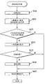
Specifically, as shown in figure 40, path validation function 14d is in step S101, the patient that become object of analyzing stored in CT image data storage portion 12 bronchus structure, in step S102, the bronchus structure data of retrieval analog structure the data base that the bronchus structure data by the past that make up from CT image data storage portion 12 constitute.
And, in step S103, path validation function 14d judges whether to exist the bronchus structure data in above past of similar predetermined similarity to the patient's who becomes object bronchus structure data, when existing, in step S104, show the above consistent path domain of predetermined similarity.As display packing, for example pass through
(1) on the MPR image shown in Figure 41
(2) on the graph thinning model image shown in Figure 42
(3) on volume data (volume data) image shown in Figure 43
Wait path domain on each image to show and realize.
In addition, on each image in Figure 41~Figure 43, utilize path domain 1001 and inconsistent path domain 1002 consistent on the path till color separation is presented at terminal point scope 1000.
And, in step S105, judge whether the emulation of shown path enforcement based on the VBS image of the bronchus structure data in past, when implementing emulation, in step S106, VBS image as shown in figure 44 is such, enforcement by the patient who becomes object in the path domain of unanimity the VBS image and VBS image in the past relatively show the emulation of carrying out, in step S107, the bronchus structure data in past are registered among the data base of CT image data storage portion 12 end process as the simulation object data.
In addition, in Figure 44,, that is, show the 1VBS image display area 1010 of the patient's's (current data) who becomes object VBS image by showing by the picture that constitutes with the lower part; The 2VBS image display area 1011 that shows the VBS image of similar (past data); And the draw runner 1012 that is used to specify the display box of these VBS images.
The invention is not restricted to the embodiments described, can carry out various changes, modification etc. in the scope that does not change aim of the present invention.
Claims (7)
1. one kind is inserted back-up system, it is characterized in that having:
The virtual image generation unit, it generates the virtual image of described tested intravital body cavity pipeline according to the view data of the 3D region of subject;
Path initial point setup unit, it sets the initial point of endoscope to the insertion path of described tested intravital body cavity pipeline;
The region-of-interest setup unit, it sets the zone at described tested intravital concern position;
The path extraction unit, it extracts a plurality of described insertion path in the zone from described initial point to described concern position; And
The path validation unit, a plurality of described insertion path that its checking is extracted by described path extraction unit.
2. insertion back-up system according to claim 1 is characterized in that,
Described path validation unit has:
Position specifying unit, it specifies the optional position on the described insertion path that is extracted by described path extraction unit; And
Display unit shows the described virtual image by the specified described position of described position specifying unit.
3. insertion back-up system according to claim 2 is characterized in that,
Has the position mobile unit that the specified described position of described position specifying unit is moved.
4. insertion back-up system according to claim 2 is characterized in that,
Described path extraction unit extracts a plurality of described insertion paths to the position that is positioned near the described body cavity pipeline of described region-of-interest.
5. insertion back-up system according to claim 2 is characterized in that,
Described display unit shows the described insertion path that is extracted by described path extraction unit on based on multibreak reconstructed image of the view data of described 3D region.
6. insertion back-up system according to claim 2 is characterized in that,
Described display unit shows the described insertion path that is extracted by described path extraction unit on the three-dimensional reconstruction image based on the described tested intravital body cavity pipeline of the view data of described 3D region.
7. one kind is inserted back-up system, it is characterized in that having:
The virtual image generation unit, it generates the virtual image of described tested intravital body cavity pipeline according to the view data of the 3D region of subject;
Path initial point setup unit, it sets the initial point of endoscope to the insertion path of described tested intravital body cavity pipeline;
The path termination setup unit, it sets the terminal point of endoscope to the insertion path of described tested intravital body cavity pipeline;
The path extraction unit, it extracts a plurality of described insertion path from described initial point to described terminal point; And
The path validation unit, a plurality of described insertion path that its checking is extracted by described path extraction unit.
Applications Claiming Priority (2)
| Application Number | Priority Date | Filing Date | Title |
|---|---|---|---|
| JP2003374929A JP3847744B2 (en) | 2003-11-04 | 2003-11-04 | Insertion support system |
| JP374929/2003 | 2003-11-04 |
Publications (2)
| Publication Number | Publication Date |
|---|---|
| CN1874717A CN1874717A (en) | 2006-12-06 |
| CN100413458C true CN100413458C (en) | 2008-08-27 |
Family
ID=34544233
Family Applications (1)
| Application Number | Title | Priority Date | Filing Date |
|---|---|---|---|
| CNB200480032338XA Active CN100413458C (en) | 2003-11-04 | 2004-11-01 | Insert support system |
Country Status (5)
| Country | Link |
|---|---|
| US (1) | US7929014B2 (en) |
| EP (1) | EP1681012B1 (en) |
| JP (1) | JP3847744B2 (en) |
| CN (1) | CN100413458C (en) |
| WO (1) | WO2005041762A1 (en) |
Families Citing this family (33)
| Publication number | Priority date | Publication date | Assignee | Title |
|---|---|---|---|---|
| US20080286734A1 (en) * | 2005-07-20 | 2008-11-20 | Shraga Rottem | Method and Device For Image Quality Accreditation, Hands on Cme, and For Control and Analysis of Accreditation at the Enterprise Level |
| US7518619B2 (en) * | 2005-11-07 | 2009-04-14 | General Electric Company | Method and apparatus for integrating three-dimensional and two-dimensional monitors with medical diagnostic imaging workstations |
| IL181470A (en) * | 2006-02-24 | 2012-04-30 | Visionsense Ltd | Method and system for navigating within a flexible organ of the body of a patient |
| US8672836B2 (en) * | 2007-01-31 | 2014-03-18 | The Penn State Research Foundation | Method and apparatus for continuous guidance of endoscopy |
| JP5123615B2 (en) * | 2007-08-31 | 2013-01-23 | オリンパスメディカルシステムズ株式会社 | Endoscope insertion support device |
| US20090181104A1 (en) * | 2007-12-14 | 2009-07-16 | Gino Rigotti | Breast reconstruction or augmentation using computer-modeled deposition of processed adipose tissue |
| US7905595B2 (en) * | 2008-04-28 | 2011-03-15 | Crt Technology, Inc. | System and method to treat and prevent loss of visual acuity |
| CN102405010B (en) * | 2009-04-20 | 2014-07-16 | 奥林巴斯医疗株式会社 | Subject internal examination system |
| WO2011094518A2 (en) * | 2010-01-28 | 2011-08-04 | The Penn State Research Foundation | Image-based global registration system and method applicable to bronchoscopy guidance |
| US10580325B2 (en) * | 2010-03-24 | 2020-03-03 | Simbionix Ltd. | System and method for performing a computerized simulation of a medical procedure |
| WO2012029265A1 (en) * | 2010-08-31 | 2012-03-08 | 富士フイルム株式会社 | Medical treatment information display device and method, and program |
| EP2883208B1 (en) * | 2012-08-13 | 2021-02-17 | Koninklijke Philips N.V. | Tubular structure tracking |
| JP6245801B2 (en) * | 2012-12-10 | 2017-12-13 | 東芝メディカルシステムズ株式会社 | Image display apparatus and medical image diagnostic apparatus |
| US9459770B2 (en) | 2013-03-15 | 2016-10-04 | Covidien Lp | Pathway planning system and method |
| US9925009B2 (en) * | 2013-03-15 | 2018-03-27 | Covidien Lp | Pathway planning system and method |
| US9639666B2 (en) | 2013-03-15 | 2017-05-02 | Covidien Lp | Pathway planning system and method |
| US20160000414A1 (en) | 2014-07-02 | 2016-01-07 | Covidien Lp | Methods for marking biopsy location |
| AU2015283946B2 (en) | 2014-07-02 | 2019-09-12 | Covidien Lp | Real-time automatic registration feedback |
| CN106232010B (en) | 2014-07-02 | 2020-03-31 | 柯惠有限合伙公司 | System and method for detecting trachea |
| CN106659453B (en) | 2014-07-02 | 2020-05-26 | 柯惠有限合伙公司 | System and method for segmenting lungs |
| US9603668B2 (en) | 2014-07-02 | 2017-03-28 | Covidien Lp | Dynamic 3D lung map view for tool navigation inside the lung |
| US9770216B2 (en) | 2014-07-02 | 2017-09-26 | Covidien Lp | System and method for navigating within the lung |
| US9754367B2 (en) | 2014-07-02 | 2017-09-05 | Covidien Lp | Trachea marking |
| US10643371B2 (en) | 2014-08-11 | 2020-05-05 | Covidien Lp | Treatment procedure planning system and method |
| EP3324819A1 (en) * | 2015-07-23 | 2018-05-30 | Koninklijke Philips N.V. | Endoscope guidance from interactive planar slices of a volume image |
| US10986990B2 (en) | 2015-09-24 | 2021-04-27 | Covidien Lp | Marker placement |
| US10709352B2 (en) | 2015-10-27 | 2020-07-14 | Covidien Lp | Method of using lung airway carina locations to improve ENB registration |
| WO2017197114A1 (en) | 2016-05-11 | 2017-11-16 | Affera, Inc. | Anatomical model generation |
| US11728026B2 (en) | 2016-05-12 | 2023-08-15 | Affera, Inc. | Three-dimensional cardiac representation |
| JP6797557B2 (en) * | 2016-05-17 | 2020-12-09 | キヤノンメディカルシステムズ株式会社 | Medical image diagnostic equipment, medical image processing equipment and image display program |
| US10321878B2 (en) * | 2016-12-22 | 2019-06-18 | Biosense Webster (Israel) Ltd. | Pulmonary vein display in two dimensions |
| US11224392B2 (en) | 2018-02-01 | 2022-01-18 | Covidien Lp | Mapping disease spread |
| US11532244B2 (en) | 2020-09-17 | 2022-12-20 | Simbionix Ltd. | System and method for ultrasound simulation |
Citations (6)
| Publication number | Priority date | Publication date | Assignee | Title |
|---|---|---|---|---|
| US5611025A (en) * | 1994-11-23 | 1997-03-11 | General Electric Company | Virtual internal cavity inspection system |
| US5638819A (en) * | 1995-08-29 | 1997-06-17 | Manwaring; Kim H. | Method and apparatus for guiding an instrument to a target |
| JPH10137190A (en) * | 1996-11-13 | 1998-05-26 | Toshiba Iyou Syst Eng Kk | Medical image processor |
| JP2000135215A (en) * | 1998-10-30 | 2000-05-16 | Ge Yokogawa Medical Systems Ltd | Conduit guiding method and device thereof and radiation tomographic equipment |
| US6346940B1 (en) * | 1997-02-27 | 2002-02-12 | Kabushiki Kaisha Toshiba | Virtualized endoscope system |
| JP2002306403A (en) * | 2001-04-18 | 2002-10-22 | Olympus Optical Co Ltd | Endoscope |
Family Cites Families (8)
| Publication number | Priority date | Publication date | Assignee | Title |
|---|---|---|---|---|
| US5702348A (en) * | 1996-07-24 | 1997-12-30 | Vision-Sciences, Inc. | Disposable endoscopic sheath support and positioning assembly |
| US6652453B2 (en) * | 1999-03-03 | 2003-11-25 | Vincent A. Smith | Portable video laryngoscope |
| US6356940B1 (en) * | 1999-05-26 | 2002-03-12 | Brian Robert Short | Method and system of electronically logging remote user dietary information, and generating and automatically sending suggested dietary modifications |
| US20040039250A1 (en) * | 2002-05-28 | 2004-02-26 | David Tholfsen | Guidewire delivery of implantable bronchial isolation devices in accordance with lung treatment |
| ATE349944T1 (en) * | 2002-07-31 | 2007-01-15 | Olympus Corp | ENDOSCOPE |
| JP4245880B2 (en) * | 2002-08-30 | 2009-04-02 | オリンパス株式会社 | Endoscope device |
| US7473219B1 (en) * | 2003-03-07 | 2009-01-06 | Glenn Joshua P | Flexible fiber optic bronchoscope one-way valve |
| EP1681011B1 (en) * | 2003-10-31 | 2013-03-20 | Olympus Corporation | Insertion support system |
-
2003
- 2003-11-04 JP JP2003374929A patent/JP3847744B2/en not_active Expired - Lifetime
-
2004
- 2004-11-01 WO PCT/JP2004/016232 patent/WO2005041762A1/en active Application Filing
- 2004-11-01 CN CNB200480032338XA patent/CN100413458C/en active Active
- 2004-11-01 EP EP04799438A patent/EP1681012B1/en not_active Expired - Fee Related
-
2006
- 2006-04-28 US US11/414,674 patent/US7929014B2/en active Active
Patent Citations (6)
| Publication number | Priority date | Publication date | Assignee | Title |
|---|---|---|---|---|
| US5611025A (en) * | 1994-11-23 | 1997-03-11 | General Electric Company | Virtual internal cavity inspection system |
| US5638819A (en) * | 1995-08-29 | 1997-06-17 | Manwaring; Kim H. | Method and apparatus for guiding an instrument to a target |
| JPH10137190A (en) * | 1996-11-13 | 1998-05-26 | Toshiba Iyou Syst Eng Kk | Medical image processor |
| US6346940B1 (en) * | 1997-02-27 | 2002-02-12 | Kabushiki Kaisha Toshiba | Virtualized endoscope system |
| JP2000135215A (en) * | 1998-10-30 | 2000-05-16 | Ge Yokogawa Medical Systems Ltd | Conduit guiding method and device thereof and radiation tomographic equipment |
| JP2002306403A (en) * | 2001-04-18 | 2002-10-22 | Olympus Optical Co Ltd | Endoscope |
Also Published As
| Publication number | Publication date |
|---|---|
| EP1681012A1 (en) | 2006-07-19 |
| JP3847744B2 (en) | 2006-11-22 |
| EP1681012A4 (en) | 2010-02-24 |
| US20060203089A1 (en) | 2006-09-14 |
| JP2005137455A (en) | 2005-06-02 |
| US7929014B2 (en) | 2011-04-19 |
| CN1874717A (en) | 2006-12-06 |
| EP1681012B1 (en) | 2012-02-15 |
| WO2005041762A1 (en) | 2005-05-12 |
Similar Documents
| Publication | Publication Date | Title |
|---|---|---|
| CN100413458C (en) | Insert support system | |
| CN102395318B (en) | Diagnosis support apparatus and diagnosis support method | |
| CN100364479C (en) | Endoscope | |
| EP1685787B1 (en) | Insertion support system | |
| CN101219058B (en) | System and method for analyzing and displaying computed tomography data | |
| Mahmud et al. | Computer vision and augmented reality in gastrointestinal endoscopy | |
| CN101669807B (en) | Image display device, image display method and image display program | |
| JP2023171651A (en) | Systems and methods for generating and displaying study information of in vivo image stream | |
| JP3930423B2 (en) | Endoscope device | |
| US20060195033A1 (en) | Insertion support system for specifying a location of interest as an arbitrary region and also appropriately setting a navigation leading to the specified region | |
| CN100562284C (en) | Image display device, method for displaying image | |
| US20090054729A1 (en) | Endoscope insertion support system and endoscope insertion support method | |
| JP4922107B2 (en) | Endoscope device | |
| JP2010042065A (en) | Medical image processor, processing method | |
| CN101069655A (en) | Method and apparatus for examining hollow lumen by virtual endoscope | |
| CN101273916B (en) | System and method for evaluating status of patient | |
| CN101229048B (en) | Multi-section reconstructed image generation device | |
| JP4776954B2 (en) | Endoscope insertion support device | |
| US20070298396A1 (en) | Computer executable dynamic presentation system for simulating human meridian points and method thereof | |
| JP4493423B2 (en) | Endoscope insertion support device | |
| US20180090176A1 (en) | Medical image storage and reproduction apparatus, method, and program | |
| JP4546064B2 (en) | Insertion simulation device | |
| JP4573517B2 (en) | Insertion support system | |
| JP4575143B2 (en) | Insertion support system | |
| Zhao et al. | Image-guided system for radial-probe endobronchial ultrasound bronchoscopy |
Legal Events
| Date | Code | Title | Description |
|---|---|---|---|
| C06 | Publication | ||
| PB01 | Publication | ||
| C10 | Entry into substantive examination | ||
| SE01 | Entry into force of request for substantive examination | ||
| C14 | Grant of patent or utility model | ||
| GR01 | Patent grant |