CN100426313C - Boundary extracting method, program, and device using the same - Google Patents
Boundary extracting method, program, and device using the same Download PDFInfo
- Publication number
- CN100426313C CN100426313C CNB2004100841944A CN200410084194A CN100426313C CN 100426313 C CN100426313 C CN 100426313C CN B2004100841944 A CNB2004100841944 A CN B2004100841944A CN 200410084194 A CN200410084194 A CN 200410084194A CN 100426313 C CN100426313 C CN 100426313C
- Authority
- CN
- China
- Prior art keywords
- edge
- image
- candidate item
- edge section
- search
- Prior art date
- Legal status (The legal status is an assumption and is not a legal conclusion. Google has not performed a legal analysis and makes no representation as to the accuracy of the status listed.)
- Expired - Fee Related
Links
Images


Classifications
-
- H—ELECTRICITY
- H04—ELECTRIC COMMUNICATION TECHNIQUE
- H04N—PICTORIAL COMMUNICATION, e.g. TELEVISION
- H04N1/00—Scanning, transmission or reproduction of documents or the like, e.g. facsimile transmission; Details thereof
- H04N1/04—Scanning arrangements, i.e. arrangements for the displacement of active reading or reproducing elements relative to the original or reproducing medium, or vice versa
-
- G—PHYSICS
- G06—COMPUTING; CALCULATING OR COUNTING
- G06V—IMAGE OR VIDEO RECOGNITION OR UNDERSTANDING
- G06V30/00—Character recognition; Recognising digital ink; Document-oriented image-based pattern recognition
- G06V30/40—Document-oriented image-based pattern recognition
- G06V30/41—Analysis of document content
- G06V30/412—Layout analysis of documents structured with printed lines or input boxes, e.g. business forms or tables
-
- G—PHYSICS
- G06—COMPUTING; CALCULATING OR COUNTING
- G06V—IMAGE OR VIDEO RECOGNITION OR UNDERSTANDING
- G06V10/00—Arrangements for image or video recognition or understanding
- G06V10/20—Image preprocessing
- G06V10/24—Aligning, centring, orientation detection or correction of the image
Abstract
An edge detecting method detects edge segments by searching all of the search lines forming an image from an end of the image in a direction perpendicular to the edges. If a line whose edge segment cannot be detected exists, a search is made in all of the search lines from the vicinity of the center of the image toward the end of the image, whereby edge segments are detected. A linear edge is determined from edge segments. A plurality of edge candidates are obtained from the edge segments for all of the search lines, and an optimum candidate is selected from among the edge candidates. Ruled lines are extracted from the source document in the image, and an optimum candidate is selected based on a comparison with a ruled line. As a result, an edge of the source document can be detected with high accuracy even if an image on a background side is unstable, or if materials of the background and the source document are similar.
Description
Technical field
The present invention relates to image processing apparatus, and more specifically relate to from using image processing apparatus to catch and comprise the technology of the image extraction page part of background.
Background technology
As the device that can read the source file of making by paper etc., known to scanner, duplicating machine, facsimile recorder etc.Using this image processing apparatus to read source file and is undertaken by place the source file lid at the source file dorsal part at the reading face of image read-out the front side (being read face) by source file is set usually.When reading images, light shines the source file front side of setting from reading face one side, and uses at the optical pick-up unit (CCD) that reads surperficial side configuration and read reflected light.If the size of source file is less than reading face, then the lid of source file (hereinafter referred to as background) also appears at around the source file of seeing from reading face one side.Owing to also read background except the front side of source file when reading images, the view data of acquisition becomes background naturally and appears at source file data on every side.
So, the inventor etc. disclose a kind of technology, this technology does not need special scheme when catching image, and by utilizing the difference between background material and the source file, only uses the Flame Image Process of carrying out after image capturing to come the edge (patent document of realizing among Fig. 2 1) of detection resources file.
The open No.2002-370596 of [patent document 1] Jap.P..
Yet the problem of this technology is, if the materials similar of the material of background and source file, if or the judder on the background, as in tack scanner reading images, the accuracy of rim detection worsens.
Summary of the invention
The objective of the invention is to provide a kind of technology, though the judder on the background, even or the materials similar of the material of background and source file, this technology also can be with the edge of pinpoint accuracy detection resources file.
In first aspect, the invention provides and a kind ofly detecting the boundary detection method at an edge that constitutes the source file border, comprising: by detect the step of edge section at all search rows that form image from the end search of image perpendicular to the direction at edge by catch the difference between the materials used in the image that source file obtains with scanner; Detect the step of edge section under the situation of the search row that exists its edge section not to be detected, this is by carrying out from searching for all search rows to this end of image near the center of image; And determine the step of linear edge from edge section for all search rows, this step of determining linear edge comprises: the candidate item determining step obtains a plurality of edges candidate item for all search rows from edge section; And selection step, among a plurality of edges candidate item, select optimum candidate item, described boundary detection method also comprises: the source file from image extracts the step of ruling, and wherein said selection step comprises the step that is used for based on select optimum candidate item with the comparison of ruling.
In addition, the present invention can provide a kind of Boundary Detection device, it is used for from by catch the image extraction source file border that source file obtains with scanner, this device comprises: first detecting unit, be used for by detecting edge section at all search rows of searching for the formation image from an end of image perpendicular to the direction at edge, wherein each search row comprises a plurality of search block, the height of each search block greater than a pixel, and is detected as edge section with the corresponding search block of the part at the edge that will detect greater than a pixel and width; Second detecting unit is used under the situation of the search row that exists its edge section not to be detected, by detecting edge section from should end searching for all search rows to image near the center of image; And determining unit, determine linear edge for all search rows from edge section, this determining unit comprises: the candidate item determining unit obtains a plurality of edges candidate item for all search rows from edge section; And selected cell, among a plurality of edges candidate item, select optimum candidate item, described Boundary Detection device also comprises: extraction unit, and the source file from image extracts ruling, and wherein said selected cell comprises the unit that is used for based on select optimum candidate item with the comparison of ruling.
The present invention also provides a kind of duplicating machine, be used for from by catch the border of the image extraction source file that source file obtains with scanner, comprise: first detecting unit, be used for by detecting edge section at all search rows of searching for the formation image from an end of image perpendicular to the direction at edge, wherein each search row comprises a plurality of search block, the height of each search block greater than a pixel, and is detected as edge section with the corresponding search block of the part at the edge that will detect greater than a pixel and width; Second detecting unit is used under the situation of the search row that exists its edge section not to be detected, by detecting edge section from should end searching for all search rows to image near the center of image; And determining unit, determine linear edge for all search rows from edge section, this determining unit comprises: the candidate item determining unit obtains a plurality of edges candidate item for all search rows from edge section; Selected cell, be used for selecting the best candidate item from a plurality of edges candidate item, described duplicating machine also comprises: extraction unit, and the source file from image extracts ruling, and wherein said selected cell comprises the unit that is used for based on select optimum candidate item with the comparison of ruling.
Description of drawings
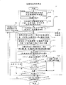
Fig. 1 is a process flow diagram, and expression is used for from the operation at an edge of image detection source file of catching according to the present invention;
Fig. 2 represents the formation of image processing apparatus according to a preferred embodiment of the present invention;
Image of Fig. 3 example shown extracts the border according to the present invention from it;
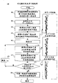
Fig. 4 is a process flow diagram, the details of an example of the process in presentation graphs 1 step 100;
Fig. 5 A and 5B represent the eliminating in printable character district, and this is to use the district of printable character shown in Fig. 1 exclusion process to carry out;
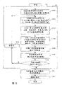
Fig. 6 is a process flow diagram, and feature is emphasized the details of process one example in presentation graphs 1 step 104;
Fig. 7 is a tables of data, and expression uses the feature shown in Fig. 6 to emphasize process, the result of the 2DFFT that a sample image is carried out;
Fig. 8 is a process flow diagram, is illustrated in the details of an example of the process of the edge section that is used to obtain the edge candidate item in the step 106 of Fig. 1;
The edge section that Fig. 9 example shown uses the tentative edge deterministic process (step 106) of Fig. 8 to obtain;
Figure 10 is a process flow diagram, the details of a plurality of edge of (step 108) of presentation graphs 1 candidate item leaching process one example;
From a plurality of tentative edges candidate item, select to be parallel to most the comparison in the method for tentative edge candidate item of ruling in Figure 11 A example shown step 110;
Figure 11 B is a process flow diagram, and example shown step 110 selects to be parallel to most the method for the tentative edge candidate item of ruling from a plurality of tentative edges candidate item;
Figure 12 is a process flow diagram, the details of edge deterministic process (step a 112) example of presentation graphs 1;
Figure 13 represents pending pixel region among Figure 15 step S120;
Figure 14 is a process flow diagram, and the operation of rim detection principle extraction source file of the present invention shown in Figure 1 is used in expression;
Figure 15 represents two class searching methods when 4 edges of detection resources file in Figure 14;
Figure 16 is a block diagram of simplifying, and expression loads according to Boundary Extraction program of the present invention to computing machine, and carries out an example of this program;
Figure 17 is a block diagram of simplifying, and expression loads according to Boundary Extraction program of the present invention to computing machine, and carries out one second realization example of this program;
Figure 18 is a process flow diagram, and example shown is used the operation according to first image processing system of Boundary Extraction program of the present invention;
Figure 19 is a process flow diagram, and example shown is used the operation according to second image processing system of Boundary Extraction program of the present invention; And
Figure 20 is a process flow diagram, and example shown Boundary Extraction program according to the present invention is from the operation of a system of the image extraction source file of catching, the line character of going forward side by side identification.
Embodiment
Followingly describe in detail according to a preferred embodiment of the invention with reference to accompanying drawing.If described identical composed component in a plurality of accompanying drawings, then these elements are with identical labelled notation.
[first preferred embodiment]
Fig. 2 illustrates the formation of image processing apparatus according to a preferred embodiment of the present invention, the image extraction source file part of this device from catching, and use the source file part.In this diagram, image processing apparatus 1 comprises a main body 12, and a source file lid 10, is used to cover the source file that is placed on the main body end face.Constituting of main body 12: scanner mechanism unit 14, this is the mechanical part that reads the scanner that is placed on the source file on main body 12 end faces; Image print mechanism unit 16, this is the mechanical part of an image printer; And electronic device unit 20, it uses the compounding practice between scanner mechanism unit 14 and the image print mechanism unit 16 to carry out required function.As everyone knows, the constituting of electronic device unit 20: control module 22, it comprises CPU (CPU (central processing unit)), ROM (ROM (read-only memory)), RAM (random access storage device) or the like, they are all not shown; Store the auxilary unit 26 of each class method and data; And input/output interface 24, be used to provide the interface between scanner mechanism unit 14 and the image print mechanism unit 16.Auxilary unit 26 storage operating systems (OS) 32, scanner drive 34, it is by catching image with scanner mechanism unit compounding practice, Boundary Extraction program 36, it is from using the image detection edge of scanner from catching, and each class method 38, they are used to realize the function of image processing apparatus 1.As image processing apparatus shown in Figure 2, can use any device, as long as it can extract and pack processing is contained in source file part in the image of catching with scanner.The example of image processing apparatus 1 comprises duplicating machine, facsimile recorder, OCR device, bar tape processing unit or the like automatically.
After the precalculated position is placed and read source file on the main body of image processing apparatus 1, call Boundary Extraction program 36 and carry out, so that image extraction source file area from reading.In other words, the left side of detection resources file, the right side, upper and lower edge.Can use similar process to detect a left side, the right side, upper and lower edge.Thereby, at first describe for example detection of left side edge of an edge.
Fig. 1 is a process flow diagram, expression by control module 22 under the control of in accordance with a preferred embodiment of the present invention Boundary Extraction program 36, from the operation at an edge of the image detection source file of catching.The major part of Fig. 1 is open by the Japanese Patent Application Publication No.2000-37059 (patent document 1) that above-mentioned the applicant submits to.Thereby, represent by thick line among Fig. 1 that according to the operation steps of principle of the present invention the detailed description of the disclosure content is omitted.
Fig. 3 illustrates the part of an image, from the border that this part uses Boundary Extraction program 36 to extract page (or source file).In this diagram, the dotted line of vertical direction is the left hand edge of source file, and the right side part of left hand edge is a source file, and the zone that the left vertical of left hand edge is pointed to is the lid of source file.Source file comprises level and vertical ruling.The operation that is used for detecting this image source file edge is below described.
When calling Boundary Extraction program 36, in the step 100 print character district of detection resources file at first.Then, in step 104 and in the process afterwards, get rid of this print character district from enabling objective.Specifically, for example use print character district exclusion process shown in Figure 4, identification and storage have 200 or the pixel region of littler RGB shade value, and will its from step 104 and after ferret out remove.Shown in Figure 5 from original image to the eliminating in print character district.The exclusion process in print character district can be carried out according to process flow diagram shown in Figure 4.Yet this process is not limited to this realization, and can use other methods that are suitable for to carry out.The details of Fig. 4 will be described after a while.
In accordance with a preferred embodiment of the present invention, extract vertical and horizontal ruling by use known method search to detect the print character district in step 102 in step 100.Then, use detected ruling confirmed test edge (step 110 of Miao Shuing after a while) here.
Then, in step 104, carrying out feature by following mode emphasizes: use 2DFFT (2 dimension rapid fourier change) that each piece that is provided with in the field of search is obtained frequency spectrum, obtain the mean value of high fdrequency component, low frequency component and the DC component of the frequency spectrum that is obtained, a peaked half width of frequency spectrum is set to frequency distribution, and the mean value and the frequency distribution of the high fdrequency component, low frequency component and the DC component that obtain are set to characteristic quantity.For example can use feature shown in Figure 6 to emphasize that process carries out this feature and emphasize.Yet feature emphasizes to be not limited to this realization, but can use other suitable methods to realize.The details of Fig. 6 will be in explanation after a while.Fig. 7 is a tables of data, and expression uses feature shown in Figure 6 to emphasize that process carries out the result of 2DFFT (2 dimension rapid fourier change) to sample image.
In step 106, use the characteristic quantity that obtains in step 104 to obtain an edge then, and determine that the edge of this acquisition is tentative edge.This tentative edge determining step S106 comprises edge candidate item determining step 106, polygon edge candidate item extraction step 108, and step 110 is selected at tentative edge.
Specifically, in step 106, use the characteristic quantity that obtains in step 104 to carry out edge candidate item deterministic process.At first, in step 210, the direction of search from the end in print character district to beginning is set, and piece at the beginning is set.In step 220, as shown in Figure 9, search for all row by the characteristic quantity that uses each piece in the direction of search and obtain each edge section.Note, corresponding to the edge and equal to use the part of the search block length that search procedure detects to be called as edge section.Then, in determining step 250, determine whether to exist its edge section not have detected search row.If exist its edge section can not detected row, the direction of search be set to from the print character district to this end (left end is because example is the detection of left hand edge in this example), and piece at the beginning is set.Then, flow process is returned step 220, to the left all search rows is searched at this left end from the print character district, so that detect edge section.Under this situation, search is therefrom carried out in the mind-set left side.Yet,, can make search more effective by getting rid of the print character district.To the example of a realization of step 106 described after a while.
According to the present invention, extract a plurality of edges candidate item from the edge section of the edge candidate item that obtains in step 106.The details of this process one example is shown in Figure 10.In this diagram,, the whole row of the edge section that obtains in step 106 are carried out linear proximity, and the row of linear proximity are set to the first edge candidate item at first at step S460.In step 462, obtain the x axle difference Δ x between each piece.Here, " the x axle difference Δ x between each piece " indication poor between direction of search neighboring edge fragment position.Because the direction of search is a level in the present example, this difference indication poor between the position (being the x coordinate) of transverse axis (being the x axle) direction neighboring edge section.In step 464, obtain the average absolute of x axle difference Δ x.In step 466, obtain to have got rid of the piece group (tentatively be called " along the piece group at center ") of the absolute value of its x axle difference Δ x above the piece of mean value, that is, and an edge section set at the center during relatively the edge section that obtains along step 106 is listed as.In step 468, it is 0 that threshold value is set.
Then at step S470, obtain as by to a piece group (the piece group that tentatively is called along the center and keeps right) of adding a piece group (the edge section set of promptly keeping right) the gained result in the positive scope of its x axle difference Δ x in threshold value along the central block group.In step 472, obtain as by to a piece group (the piece group that temporarily is called along the center and keeps left) of adding a piece group (the edge section set that promptly keep left) the gained result of its x axle difference Δ x in the negative scope of threshold value along the central block group.
In step 474, determine that whether threshold value reaches its x axle difference Δ x is peaked then.X is not peaked if threshold value reaches its x axle difference Δ, and then predetermined threshold value increment α is added to current threshold value, and flow process is returned S470.Repeating step 470 to 476 then.If reaching its x axle difference Δ x in step 474 threshold value is peaked, then carry out linear proximity respectively, and the result is set to the edge candidate item for each the piece group that obtains.Like this, can obtain a plurality of edges candidate item.By threshold value increment α is set is suitable value, edge candidate's item number that scalable will obtain.
After having extracted a plurality of edges candidate item like this, the edge candidate item that is parallel to the ruling that obtains in step 102 most is confirmed as tentative edge.That is, with the same direction in the edge of current detection in be parallel to ruling (ruling of vertical direction is because what detect in this example is left hand edge) most the edge candidate item be confirmed as tentative edge.If current detected edge is on top or the horizontal edge of bottom, the edge candidate item that then is parallel to most ruling in a horizontal direction is defined as tentative edge.Figure 11 example is illustrated in the method that is parallel to an edge candidate item of ruling in the step 110 from the selection of a plurality of edges candidate item most.In Figure 11 A, difference between the x coordinate of the point that the transverse axis by ruling one end and each edge candidate item are intersected and the x coordinate of an above-mentioned end is defined as Δ T, and the difference between the x coordinate of the x coordinate of the point that the transverse axis by the ruling other end and above-mentioned edge candidate item are intersected and the above-mentioned other end is defined as Δ B.The operation that relates to the process flow diagram shown in Figure 11 B is below described.In step 482, obtain the top of ruling in the horizontal direction and the poor Δ T between each edge candidate item, and the poor Δ B between the bottom of ruling and each the edge candidate item.In step 484, select its difference to be minimum edge candidate item, and be defined as the heuristic edge according to Δ T and Δ B.In the example shown in Figure 11 A, edge candidate item 2 is selected, because its difference according to Δ T and Δ B is less.
Edge detection process can stop for final edge at the edge that step 110 is selected by determining.Yet in this preferred embodiment, in order to improve the accuracy of rim detection, here the edge of Huo Deing is set to tentative edge, and carries out the rim detection of high precision more (make processed piece littler) near this tentative edge, so that filter out accurate marginal position in subsequent step.
In other words, in step 112, determine final edge based on the tentative edge that obtains in step 110.The details of step 112 is shown in Figure 12.In step 120, as shown in figure 13, on the left side and right 16 pixel width at the tentative edge that step 110 obtains, in the module unit of 32 vertical pixel * 1 horizontal pixels, extract feature, and be confirmed as edge section based on the peak of the feature of extracting.In step 122, the edge section that obtains is carried out linear proximity, to obtain straight line.Then in the robustness of step 124 is proofreaied and correct, for edge section set by obtaining from step 120, the straight line that uses step 122 acquisition is as benchmark, eliminating is not suitable for being defined as an edge at edge (from the straight line edge too far away that step 122 obtains) and the edge aggregation that obtains is carried out linear proximity, thereby obtains final edge.The details of step 120 will described after a while.
As mentioned above, in the preferred embodiment of Fig. 1, determine the edge candidate item by using the search of in step 106, in the big module unit of 32 vertical pixel * 4 horizontal pixels, carrying out, and by using near the search of tentative definite edge, in the little module unit of 32 vertical pixel * 1 horizontal pixels, carrying out to increase degree of accuracy in step 112, thereby obtain an edge.Yet the present invention not only is applicable to the method by an edge of change piece size detection two stages by this way.The latter half of the rim detection of the search that use is carried out in little module unit can omit.For example, step 112 can be omitted, and edge detection process shown in Figure 1 can stop after execution in step 110.
In a word, principle of the present invention is: (1) is if the row that exists its edge section not to be detected from the result of the image one end search row of catching as the difference between the materials used, then by near the center (a preferably end in print character district) detect edge section to each row of an end reverse search, and (2) select the most parallel edge candidate item of the preceding therewith ruling that extracts as the edge from the edge candidate item after the fixed a plurality of linear edge candidate item of the edge section Lieque that obtains.In above preferred embodiment, use bulk (with relative low accuracy) to obtain tentative edge in step 104 and 106, and near tentative edge, use fritter (with higher accuracy) to obtain final edge in step 112.Yet, the invention is not restricted to by this way to obtain the method at edge two stages.As long as it obtains an edge by search for each row from image one end of catching, any method all can be used as edge detection method.So, as long as it satisfies this purpose, step 100,104,220 and 112 can any method realize.As mentioned above, step 112 can be omitted.
Here, describe step 100 in detail, 104,196 and 112 examples of realizing.These steps can be used as any form realization and needn't be restricted to following example, as long as they satisfy purpose.
The eliminating in<print character district 〉
In operating process shown in Figure 4, the position of the begin column that at first is read among the source file image A that frame shown in Figure 3 gets up on the plane of delineation is set to the position (S300) at image A top.Then, be arranged in the pixel that Fig. 3 is provided with capable left end and be set to read target (S302).Here, read the RGB shade value that pixel is set, and determine whether the value that reads surpasses RGB shade value 200.This value in this example be scheduled to and be the benchmark (S304) that is used to get rid of as the pixel in print character district.Can be dependent on source file as the rgb value of this benchmark of determining suitably is provided with.If the rgb value of the pixel that reads surpasses 200, determine that then pixel is not the print character district, and be set to the next one with the next pixel on right side in the delegation and read target (S306).Perhaps, if the rgb value of the pixel that reads at step S304 is equal to or less than 200, then tentatively suppose to have the print character district, and flow process forwards the noise deterministic process at next step S308 in this district.At step S308, determine whether to exist a pixel, its position with at the tentative pixel that is assumed to be print character district on the plane of delineation of step S304 in succession, and the tentative print character district that is assumed to be of this pixel.If determine that at step S308 pixel does not in succession exist, then flow process forwards the process of step S306 to, and is set to read target with the next pixel on current processed pixel right side in the delegation, and among the execution in step S306 and process afterwards.
If two pixels in succession tentatively are not assumed to be the print character district, this means that these pixels probably are because the noise that causes with the incoherent stain in print character district etc.Setting as the pixel number in succession of this benchmark of determining can suitably be carried out on demand.If determine that at step S308 pixel in succession exists, then these pixels are set to from the initial detected print character of the left end of image A shown in Figure 3 district (step S310).At step S312, determine whether leave pending pixel in this row then.If determine to leave pending pixel in this row at step S312, then flow process enters the process of step S306, and handles pixel similarly by above-mentioned steps.If determine not stay pending pixel in this row, then and then determine whether this row is at image A shown in Figure 3 bottom last row (step S314) to be read at step S312.If step S314 determine this capable be not last row, then be provided with on the plane of delineation near the delegation (step S316) under this row, and from the capable left end repeated execution of steps S302 that is provided with and process afterwards.Scannings of all row in finishing image A shown in Figure 3 promptly when the scanning of finishing up to above-mentioned last row, are determined the row that current behavior is last, and are stopped this process.
<feature is emphasized 〉
Emphasize that in feature step 104 and edge section detect in the step 220, the region of search of image A (getting rid of the image in print character district from it) is divided into big relatively pixel block, such as each piece of 32 vertical pixels * 4 horizontal pixels, and each piece carried out these processes.
In operational flowchart shown in Figure 6, the piece that the image A top left at first is set is begin block (step S500).Based on the information among Fig. 3 (the print character district of the pixel that identifies in the step 100 is got rid of in this information indication in the print character district of Fig. 1), determine whether current block comprises print character district (step S502) shown in Figure 5 then.If determine that at step S502 current block comprises the print character district among Fig. 4, then adjacent with current block piece is re-set as zone pending in the image A (step S504).If determine that at step S502 current block does not comprise the print character district among Fig. 4, then the current block in the module unit is carried out known two-dimentional rapid fourier change process (being designated hereinafter simply as 2DFFT), and obtain the frequency spectrum (step S506) of current block.Here, the high fdrequency component of obtaining acquired current block frequency spectrum (is assumed to be 1/2 π≤ω<3/4 π.ω be the indication frequency variable) mean value (step S508).
Then, obtain the mean value (step S510) of the low frequency component (being assumed to be 0<ω<1/2 π in this example) of acquired current block frequency spectrum.Then, obtain the mean value (step S512) of the DC component (being assumed to be ω=0 in this example) of acquired current block frequency spectrum.Fig. 7 example illustrates the actual measurement data of above-mentioned each the component mean value that obtains for each piece in the rectangle region of 32 vertical pixel * 212 horizontal pixels of such search.The indication of this actual measurement data is respectively to the result of calculation of RGB, so that understand the fluctuation in each rgb value.X coordinate among this figure is corresponding to the X-direction of image A shown in Figure 3, and indication is when the left end of rectangle region shown in Figure 3 being considered as the X true origin, the value of the pixel number when right counting pixel number.Fig. 7 further indicates, with according to from shown in Figure 3 and by a position consistency of each pixel number of the rectangular area left end of X coordinate convention, as DC component (the DC component R of each RGB, G, and B) shade value is as each RGB low frequency component (low frequency component R, G, and B) spectrum value, and as the spectrum value of each RGB high fdrequency component (high fdrequency component R, G, and B).In above-mentioned steps, obtained the mean value of three type component.Here, further obtain half width from the frequency spectrum of current block, and the half width that is obtained is set to the frequency distribution (step S514) of current block.Half width is the interval in two cycles in the peak period neighborhood, the intensity of half-peak value in the frequency distribution that its indication obtains when level and Z-axis are defined as cycle of frequency spectrum and intensity respectively.The mean value of each component that obtains to S512 at step S508 and the characteristic quantity (step S516) that is set to current block in the frequency distribution that step S514 is provided with.Here, determine whether executed said process (step S518) for all pieces that add the source file image A of frame shown in Figure 3.If determine to have the to be scanned piece adjacent with current block at step S518, then flow process enters step S504, and next piece to be scanned is re-set as pending zone in the image A wherein shown in Figure 3, and carries out said process.If at definite all the piece executed said process for image A of step S518, and do not have the to be scanned piece adjacent with current block, this process stops.4 characteristic quantities in this operating process, have been obtained.Yet characteristic quantity is not limited to this four characteristic quantities, but can add the additional features amount.As mentioned above, emphasize in the step 104, can extract all kinds of characteristic quantities the module unit of preliminary dimension, this image is carried out print character district get rid of process in step 100 from the source file image A that adds frame in the feature of Fig. 1.
Determining of<edge candidate item 〉
Fig. 8 is a process flow diagram, realizes example for one that is illustrated in the edge candidate item determining step 106 of Fig. 1 to the process of the edge section that obtains the edge candidate item.The feature that this operating process is based on Fig. 1 emphasizes that all kinds of characteristic quantities that obtain in the step 104 carry out.
In this operating process, at first in each module unit of 32 vertical pixel * 4 horizontal pixels that the area dividing of image A shown in Figure 3 is, determine the enabling objective scope of image, and corresponding process scope (step S1100) is set.The process scope determines by the enabling objective scope carries out seeing as to the print character district from the left end (print character district blackening among this Fig. 5 B) of image A in this example.When having determined the process scope like this, the delegation at image A top is set to read from it begin column (step S1102) of piece.Here, carry out the process that (step S1104) is used for the weighting of definite above-mentioned all kinds of characteristic quantities, this process will be in following detailed description.In step 210, to the print character district direction of search is set then, and is set to begin block at the piece of image A top left from this end.Then, obtain each mean value (up to two pieces adjacent with current block and in succession) (step S1108) of the characteristic quantity that obtains at step S104 in the left side for the piece also adjacent in succession in the left side with current block.The mean value of each characteristic quantity that obtains like this is used for process shown in Figure 8 (step S1110) then.In the step S1110 of Fig. 8, obtain each characteristic quantity of current processed piece and the variable quantity of each characteristic quantity between the mean value of each characteristic quantity that step S1108 obtains.
The variable quantity of each characteristic quantity of Huo Deing is by the weighting of specific characteristic amount respectively like this, these weightings be to use that weighting deterministic process among the step S1104 obtains or in advance with statistical method obtain (preferably, high fdrequency component, low frequency component, the weighting of DC component 1 and frequency distribution is set to 1,2,1 and 1 respectively), add the weighting specified amount, and the value of adding is set to the changing features amount (step S1112) of current block.Here, execution is used for obtaining the process (step S1114) to the changing features amount peak value of each piece setting at step S1112.To describe the process that is used to obtain peak value (peak detection process) that relates to after a while in detail here.Carry out the peak value definite (step S1116) of current block changing features amount then based on above-mentioned peak detection process.If determine that at step S1116 peak value does not exist, determine further then whether the piece of secondary scan is print character zone (step S1118) down.If determine that at step S1118 the piece of secondary scan is not the print character district down, determine further then whether this piece is the piece (step S1120) that leaves 1 piece with central block in the direction of scanning side.If determine that at step S1120 this piece and central block leave 1 distance in the direction of scanning side, determine then whether current processed piece is the piece (step S1122) that is positioned at last row.Perhaps,, determine that then current processed piece is the piece corresponding to the edge, and this part tentatively is determined to be in the edge (step S1124) of source file image left end in this example if determine to exist peak value at step S1116.Flow process enters the said process at step S1122 then.If determine that at step S1118 current processed piece is the print character district, then flow process enters the process of step S1122.
If determine that at step S1120 this piece is not to leave the piece of 1 piece with current block in the direction of scanning side, then flow process enters the process of step S1126, and the next piece that is scanned is set to pending piece.Repeat then in step S1108 and process afterwards.If determine that at step S1122 current processed piece is not the piece that is arranged in last row, then flow process enters the process of step S1126.Then, carry out in step S1126 and process afterwards.Perhaps, if determine that at step S1122 current processed piece is the piece that is arranged in last row, then flow process enters the process of subsequent step 250.In step 250, determine whether the row that exists its edge section not to be detected.If the row that exists its edge section not to be detected, then the direction of search is set to from the print character district to this end of image A, and in step 260 begin block is set.Flow process enters and turns back to step S1108 then.If at the definite row that does not exist its edge section not to be detected of step S250, then this edge candidate item deterministic process stops.
<step 120 (high-precision rim detection) 〉
In this operation steps, marginal position, the scope (32 vertical pixel * 1 horizontal pixels) that lays respectively at 16 back with the preceding pixels of pixel column among Fig. 9 at first are set to enabling objective (step S1700) in the tentative delegation that is set to the image A top in direction of scanning.Then, the pixel column that is set to have 32 vertical pixel * 1 horizontal pixel scope of a module unit in this process.Carry out the one dimension rapid fourier change for the above-mentioned scope in this unit of pixel column, and obtain the frequency spectrum (step S1702) of each pixel column.Figure 13 illustrates the enabling objective scope for delegation.This diagram illustrates the enabling objective scope for the delegation of the pixel column that comprises linear proximity shown in Figure 9.Rectangular area 1800 shown in Figure 13 becomes the enabling objective scope by the row 1802 of dotted line indication.Also to other capable setting up procedure target zones in a similar fashion, though this does not specifically illustrate.At the amplifier section of rectangle region 1800, illustrate by the position relation between the above-mentioned scope of tentative edge that is defined as marginal position and enabling objective.Prove from this diagram, be arranged in respectively behind 16 by the tentative edge of the central line of this figure indication and preceding pixel column (its each be 32 vertical pixel * 1 horizontal pixels), be confirmed as the scope of said process target.After step S1702 obtains a frequency spectrum, in the unit of above-mentioned pixel column, obtain the mean value of each component (high frequency, low frequency and DC component) and the frequency distribution (step S1704) of frequency spectrum.Then weighting is specified in each component and frequency distribution, they be in the step S1104 of Fig. 8, obtain or obtain with statistical method in advance, each pixel column is added the weighting designated value, and the value that obtains is set to the eigenwert (step S1706) of pixel column.Here, the eigenwert of each pixel column is carried out known wavelet transform (step S1708).
Then, carry out known peak detection process, so that in order to the edge section (step S1710) in the value detection row unit of wavelet transform acquisition.Then, determine whether current processed row is the last row (step S1712) that is defined as tentative edge.If current processed capable be not last row, the row (step S1714) that the next one will be scanned then is set, and repeats in step S1702 and subsequent process.If determine that at step S1712 current processed row is last row, then stops the process in the step 120.
The detection on<the border formed by four limits 〉
As mentioned above, the edge that can high precision obtains source file.The situation of all edge extracting source files of acquisition source file is provided from the image of catching based on the above declarative description that provides.Figure 14 is a process flow diagram, and expression is used for the operation according to rim detection principle extraction source file of the present invention shown in Figure 1.Here suppose the left side of source file, the right side, top and bottom margin are respectively SL, Sr, Su, and Sd.Suppose that also current processed edge is Sx (x=L, r, u or d) in these 4 edges.Owing to described each step of main procedure among Figure 14, related generally to the flow process of this process here.
Among Figure 14, the result of the process in the step 100 and 102 can be used for not considering the follow-up search procedure of direction.Thereby, get final product beginning to carry out once these processes.In step 103, the L of indication left hand edge is set to the x of current detected edge Sx.
At step S104, each piece is obtained characteristic quantity, and carry out feature and emphasize then.In this course, use the vertical piece that points to.Thereby, must be respectively for a left side and right hand edge, and top and bottom margin execution in step 104.Must carry out subsequent step 106 to 112 to each edge.
So, when step 112 stops, determine in step 130 whether x is r.If x is not r, then the r of x for the indication right hand edge is set in step 132.Then, flow process is returned step 106, and detects right hand edge.
If determine that in step 130 x is r, this means that the detection of right hand edge stops.Thereby determine in determining step 134 whether x are the u of indication top.If x is not u, then do not stop the detection of top.Thereby in step 136 x to be set be u, and flow process is returned step 104.After having obtained the characteristic quantity of each piece, detect top for the search in the direction up and down.
If determine that at step S134 x is u, then this means the detection that stops top.Thereby determine in determining step 138 whether x are the d of indication bottom margin.If x is not d, then do not stop the detection of bottom margin.Thereby in step 138 x to be set be d, and flow process is returned step 106 to detect bottom margin.If determine that in step 138 x is d, this also means the detection that stops bottom margin.Thereby the source file leaching process stops.
Figure 15 illustrates two class searching methods when 4 edges of detection resources file in Figure 14.Method is by the fixing search direction, and detects the method at 4 edges by order ROTATING SOURCE file (on the left of being) in this diagram.Other method be by still image sensing, and order rotate the method that the direction of search detects 4 edges.Under each situation, according to the present invention, as the indication of step 106 (Fig. 1 and 12) and step 220, as from the outside to the result of all search rows of print character area searching, if have the row that its edge section can not be detected, then search for to the end from the print character district.Like this, can improve the precision of rim detection.
<various modified forms 〉
Figure 16 is the simplified block diagram of expression one embodiment, wherein loads and carry out the Boundary Extraction program of the implementation according to the present invention to a computing machine.System shown in this diagram comprises the scanner 40 of catching source file, and can store and carry out the computing machine 42 according to edge of the present invention or Boundary Extraction program 36.Use is stored in the Boundary Extraction program 36 in the computing machine 42, and the part that is included in the source file in the image of catching with scanner 40 is extracted and uses.
Figure 17 is a block diagram of simplifying, and expression second realizes example, is used for loading Boundary Extraction program according to the preferred embodiment of the invention to a computing machine, and is used to carry out this program.System shown in Figure 17 and system class shown in Figure 16 seemingly, institute's difference is further include file filing computing machine 44, it is connected to and can communicates by letter with computing machine 42.After the image extraction source file of catching according to program 36 self-scanning instrument 40, can be sent to another device to the source file that extracts at computing machine shown in Figure 17 42, such as file filing computing machine 44, and oneself does not use file.Under this situation, calculate 42 and can extract background parts from image, regulate the size of source file, or come correct tilt by the ROTATING SOURCE document image based on the information that during rim detection before the transfer source file, obtains.
Figure 18 is a process flow diagram, and the operation of the image processing system of Boundary Extraction program is according to the preferred embodiment of the invention used in its exemplary expression.At first, catch the view data (step S2400) that reads from scanner 40.Carry out the process (step S2402) that is used for the detection resources document edge according to 36 pairs of view data of Boundary Extraction program then, and obtain the marginal information (step S2404) of source file.Then, an extraction is by the image-region (source file image) (step S2408) of 4 surrounded by edges.Then, the image (step S2410) of the such source file that extracts of record.
Figure 19 is a process flow diagram, and example shown is used the operation of second image processing system of Boundary Extraction program according to the preferred embodiment of the invention.At first, the view data that reads from scanner 40 is captured computing machine 42 (step S2500).Then, carry out edge detection process (step S2502) according to above-mentioned Boundary Extraction program 36.Then, obtain the marginal information (step S2504) of source file.Here, when the edited image data, the edge that for example detect to obtain is to the minimum slope (step S2506) of the axle (X or Y-axis) of the plane of delineation, and the inclination by rotating image adjustment of data image is to eliminate slope (step S2508).Then, the image of the source file of proofreading and correct like this is recorded to image data memory cell (step S2510).
Notice that the operating process shown in Figure 18 and 19 can be combined.For example, the process among the step S2506 of Figure 19 and the step S2508 can be carried out between the step S2404 of Figure 18 and the process among the step S2408.Carry out the execution that slant correction can be convenient to follow-up process like this.In addition, can excise background image data, thereby can remove extra data, and also make required data volume reduce.This causes reducing of data quantity stored, and has improved the processing speed in the data use.
Figure 20 is a process flow diagram, and example shown is used the image extraction source file of Boundary Extraction program from catching according to the preferred embodiment of the invention, the operation of the system of the line character of going forward side by side identification.At first catch the view data (step S2700) that reads from scanner 40.Then, carry out edge detection process (step S2702), and obtain the marginal information (step S2704) of source file according to 36 pairs of view data of Boundary Extraction program.And then, in view data, determine to be different from a image-region (step S2706) by the image-region of 4 surrounded by edges.Shade grade determined, that be different from by the image-region of the image-region (source file image) of 4 surrounded by edges is become black (step S2708).At last, the execution character identifying, this process (for example is used to identify starting point, source file image top left position on the plane of delineation), be used for by for example image being extracted as target in the print character position from the starting point that is stored in storage unit etc. in advance, be used to analyze the image of extraction, and be used for extracting and be included in characters in images (step S2710) based on mode identification procedure.
Notice that this process can make up with operating process shown in Figure 19.For example, can between the step S2704 of Figure 20 and step S2706, carry out in the step S2506 of Figure 19 and the process among the step S2508.Background image becomes black like this, thereby can generate such view data, and it has and the identical technical manual of traditional image of catching from the scanner of traditional realization black background, and wherein has black background image around the frame of source file image.As a result, the device (such as the OCR treating apparatus etc.) that is used to edit the view data with conventional black background also can use the view data that obtains by image processing apparatus according to the present invention.
Above-mentioned realization example is just quoted as proof and is used for explaining realization example of the present invention.Thereby those skilled in the art can make various changes to above-mentioned realization example according to notion of the present invention or principle, revise or replenish.
For example, said process (comprising edge detection process certainly) can distribute with the form of program.Under this situation, program can store on the storage medium, such as floppy disk (registered trademark), and CD-ROM, DVD etc., and be assigned with.Perhaps program partly or entirely can be by the distribution of being used by public network such as transmission medium.
According to the present invention, if there is the row that its edge section can not be detected, then all search rows are searched for, thereby the precision that detects increases near the end to the image center of image.
In addition,, can obtain a plurality of edges candidate item from edge section, and from this a plurality of edges candidate item, select optimum candidate item, thereby further improve the precision that detects all search rows according to the present invention.
Claims (12)
1. one kind is being detected the boundary detection method at an edge that constitutes the source file border by catch the difference between the materials used in the image that source file obtains with scanner, comprising:
By detect the step of edge section at all search rows that form image from the end search of image perpendicular to the direction at edge;
Detect the step of edge section under the situation of the search row that exists its edge section not to be detected, this is by carrying out from searching for all search rows to this end of image near the center of image; And
Determine the step of linear edge for all search rows from edge section, this step of determining linear edge comprises:
The candidate item determining step obtains a plurality of edges for all search rows from edge section and waits
Option; And
Select step, among a plurality of edges candidate item, select optimum candidate item,
Described boundary detection method also comprises:
Source file from image extracts the step of ruling, wherein
Described selection step comprises the step that is used for based on select optimum candidate item with the comparison of ruling.
2. according to the boundary detection method of claim 1, wherein
Described candidate item determining step comprises
For all search rows, for all edge sections carry out linear proximity, to find out the step of edge candidate item.
3. according to the boundary detection method of claim 1, wherein
Described candidate item determining step comprises
For all search rows, for the edge section along the center in the edge section carries out linear proximity, to find out the step of edge candidate item.
4. according to the boundary detection method of claim 1, wherein
Described candidate item determining step comprises
For all search rows, for along the center and to the right edge section in the edge section carries out linear proximity, to find out the step of edge candidate item.
5. according to the boundary detection method of claim 1, wherein
Described candidate item determining step comprises:
For all search rows, for along the center and to the left edge section in the edge section carries out linear proximity, to find out the step of edge candidate item.
6. according to the boundary detection method of claim 3, wherein
Described candidate item determining step comprises
Be used for obtaining along the step of the average absolute of difference between the direction of search neighboring edge, and
Positive side step is rapid, is used for carrying out linear proximity for the absolute value by adding its difference to the edge section along the center in the set that obtains according to the edge section in the positive scope of the threshold value of mean value, and is set to the edge candidate item.
7. according to the boundary detection method of claim 3, wherein
Described candidate item determining step comprises
Be used for obtaining along the step of the average absolute of difference between the direction of search neighboring edge, and
The minus side step is used for for carrying out linear proximity by the absolute value that adds its difference to the edge section along the center in the set that obtains according to the edge section in the negative scope of the threshold value of mean value, and its set of carrying out linear proximity is set to the edge candidate item.
8. according to the boundary detection method of claim 6, wherein
Described candidate item determining step comprises
The minus side step is used for for carrying out linear proximity by the absolute value that adds its difference to the edge section along the center in the set that obtains according to the edge section in the negative scope of the threshold value of mean value, and is set to the edge candidate item.
9. according to the boundary detection method of claim 6, also comprise
Change the step of threshold value by predetermined change amount.
10. according to the boundary detection method of claim 9, wherein
Described change step comprises
The initial value that is used to be provided with threshold value is 0 step, and
If absolute value of its difference is used for the step that outage threshold changes for maximum edge section is included in the negative or positive scope according to the threshold value of mean value.
11. a Boundary Detection device, it is used for from by catch the image extraction source file border that source file obtains with scanner, and this device comprises:
First detecting unit is used for by detecting edge section at all search rows of searching for the formation image from an end of image perpendicular to the direction at edge;
Second detecting unit is used under the situation of the search row that exists its edge section not to be detected, by detecting edge section from searching for all search rows to this end of image near the center of image; With
Determining unit is determined linear edge for all search rows from edge section, and this determining unit comprises:
The candidate item determining unit obtains a plurality of edges for all search rows from edge section and waits
Option; And
Selected cell is selected optimum candidate item among a plurality of edges candidate item,
Described Boundary Detection device also comprises:
Extraction unit, the source file from image extracts ruling, wherein
Described selected cell comprises the unit that is used for based on select optimum candidate item with the comparison of ruling.
12. a duplicating machine is used for comprising from by catch the border of the image extraction source file that source file obtains with scanner:
First detecting unit is used for by detecting edge section at all search rows of searching for the formation image from an end of image perpendicular to the direction at edge;
Second detecting unit is used under the situation of the search row that exists its edge section not to be detected, by detecting edge section from searching for all search rows to this end of image near the center of image; With
Determining unit is determined linear edge for all search rows from edge section, and this determining unit comprises:
The candidate item determining unit obtains a plurality of edges candidate item for all search rows from edge section; And
Selected cell is used for selecting the best candidate item from a plurality of edges candidate item,
Described duplicating machine also comprises:
Extraction unit, the source file from image extracts ruling, wherein
Described selected cell comprises the unit that is used for based on select optimum candidate item with the comparison of ruling.
Applications Claiming Priority (3)
| Application Number | Priority Date | Filing Date | Title |
|---|---|---|---|
| JP2004-101461 | 2004-03-30 | ||
| JP2004101461A JP4598426B2 (en) | 2004-03-30 | 2004-03-30 | Boundary extraction method, program, and apparatus using the same |
| JP2004101461 | 2004-03-30 |
Publications (2)
| Publication Number | Publication Date |
|---|---|
| CN1677430A CN1677430A (en) | 2005-10-05 |
| CN100426313C true CN100426313C (en) | 2008-10-15 |
Family
ID=34926423
Family Applications (1)
| Application Number | Title | Priority Date | Filing Date |
|---|---|---|---|
| CNB2004100841944A Expired - Fee Related CN100426313C (en) | 2004-03-30 | 2004-10-15 | Boundary extracting method, program, and device using the same |
Country Status (6)
| Country | Link |
|---|---|
| US (1) | US7729536B2 (en) |
| EP (1) | EP1587295B1 (en) |
| JP (1) | JP4598426B2 (en) |
| KR (1) | KR100640035B1 (en) |
| CN (1) | CN100426313C (en) |
| DE (1) | DE602004017697D1 (en) |
Families Citing this family (31)
| Publication number | Priority date | Publication date | Assignee | Title |
|---|---|---|---|---|
| JP4844247B2 (en) | 2006-06-12 | 2011-12-28 | 富士ゼロックス株式会社 | Image processing apparatus and image processing program |
| CN101681432B (en) * | 2007-05-01 | 2013-11-06 | 计算机连接管理中心公司 | Photo-document segmentation method and system |
| JP4502001B2 (en) | 2007-12-20 | 2010-07-14 | コニカミノルタビジネステクノロジーズ株式会社 | Image processing apparatus and image processing method |
| JP4924416B2 (en) * | 2007-12-28 | 2012-04-25 | ブラザー工業株式会社 | Image reading device |
| US8174737B2 (en) | 2007-12-28 | 2012-05-08 | Brother Kogyo Kabushiki Kaisha | Image reading apparatus |
| US8284463B2 (en) | 2007-12-28 | 2012-10-09 | Brother Kogyo Kabushiki Kaisha | Image reading apparatus |
| JP4941317B2 (en) * | 2008-01-16 | 2012-05-30 | ブラザー工業株式会社 | Image reading device |
| JP4941316B2 (en) * | 2008-01-16 | 2012-05-30 | ブラザー工業株式会社 | Image reading device |
| JP2009303164A (en) * | 2008-06-17 | 2009-12-24 | Canon Inc | Image reading apparatus and method of controlling the same |
| US9177218B2 (en) * | 2008-09-08 | 2015-11-03 | Kofax, Inc. | System and method, and computer program product for detecting an edge in scan data |
| JP4821869B2 (en) * | 2009-03-18 | 2011-11-24 | 富士ゼロックス株式会社 | Character recognition device, image reading device, and program |
| JP5229050B2 (en) * | 2009-03-30 | 2013-07-03 | 富士通株式会社 | Document area extraction apparatus, method, and program from image |
| WO2010113217A1 (en) * | 2009-03-31 | 2010-10-07 | 富士通フロンテック株式会社 | Character recognition device and character recognition method |
| JP5424694B2 (en) * | 2009-04-10 | 2014-02-26 | 株式会社日立情報通信エンジニアリング | Image recognition apparatus and program |
| JP5462522B2 (en) * | 2009-05-07 | 2014-04-02 | キヤノン株式会社 | Image processing apparatus, image processing method, and program for causing computer to realize the image processing method |
| JP5290915B2 (en) * | 2009-09-03 | 2013-09-18 | キヤノン株式会社 | Image processing apparatus, image processing method, and program |
| KR101733539B1 (en) * | 2009-11-24 | 2017-05-10 | 삼성전자주식회사 | Character recognition device and control method thereof |
| US8873112B2 (en) | 2011-10-21 | 2014-10-28 | Canon Kabushiki Kaisha | Image processing apparatus and determination method |
| JP5822664B2 (en) | 2011-11-11 | 2015-11-24 | 株式会社Pfu | Image processing apparatus, straight line detection method, and computer program |
| JP5854774B2 (en) | 2011-11-11 | 2016-02-09 | 株式会社Pfu | Image processing apparatus, straight line detection method, and computer program |
| JP5871571B2 (en) | 2011-11-11 | 2016-03-01 | 株式会社Pfu | Image processing apparatus, rectangle detection method, and computer program |
| JP2013123812A (en) * | 2011-12-13 | 2013-06-24 | Canon Inc | Inspecting device, inspecting method, and computer program |
| JP6021557B2 (en) * | 2012-09-28 | 2016-11-09 | 株式会社Pfu | Image processing apparatus, image processing system, image processing method, and image processing program |
| JP5822865B2 (en) * | 2013-04-25 | 2015-11-25 | 京セラドキュメントソリューションズ株式会社 | Image processing apparatus, ruled line determination method, and ruled line determination program |
| CN105447426B (en) * | 2014-07-14 | 2018-02-02 | 株式会社理光 | Decision maker, file and picture management system and decision method |
| CN104792263B (en) * | 2015-04-20 | 2018-01-05 | 合肥京东方光电科技有限公司 | The method and apparatus for determining the region to be detected of display master blank |
| WO2017204830A1 (en) | 2016-05-27 | 2017-11-30 | Exxonmobil Chemical Patents, Inc. | Metallocene catalyst compositions and polymerization process therewith |
| JP6600090B2 (en) * | 2016-05-31 | 2019-10-30 | 株式会社Pfu | Image processing apparatus, image processing method, and program |
| CN106951855B (en) * | 2017-03-16 | 2020-04-10 | 深圳市六六六国际旅行社有限公司 | Method for positioning and cutting document in picture |
| US11760814B2 (en) | 2020-03-03 | 2023-09-19 | Exxonmobil Chemical Patents Inc. | 1,5 diazabicyclooctane ligand systems and methods therewith |
| US11829701B1 (en) * | 2022-06-30 | 2023-11-28 | Accenture Global Solutions Limited | Heuristics-based processing of electronic document contents |
Citations (4)
| Publication number | Priority date | Publication date | Assignee | Title |
|---|---|---|---|---|
| US6005683A (en) * | 1997-12-05 | 1999-12-21 | Hewlett-Packard Company | Document edge detection by linear image sensor |
| JP2002092606A (en) * | 2000-09-14 | 2002-03-29 | Sharp Corp | Image processor, image processing method and recording medium recording the same |
| CN1400807A (en) * | 2001-07-26 | 2003-03-05 | 佳能株式会社 | Image processing method and equipment, image processing system and storage medium |
| CN1423237A (en) * | 2001-11-16 | 2003-06-11 | 株式会社三丰 | Picture borderline detection system and method |
Family Cites Families (18)
| Publication number | Priority date | Publication date | Assignee | Title |
|---|---|---|---|---|
| JP2644724B2 (en) | 1985-07-12 | 1997-08-25 | 株式会社日立製作所 | Document image skew correction method |
| JP3278471B2 (en) * | 1991-11-29 | 2002-04-30 | 株式会社リコー | Area division method |
| US5452374A (en) | 1992-04-06 | 1995-09-19 | Ricoh Corporation | Skew detection and correction of a document image representation |
| JPH0637987A (en) * | 1992-07-20 | 1994-02-10 | Canon Inc | Original detector |
| JP3304404B2 (en) | 1992-07-31 | 2002-07-22 | 株式会社日立製作所 | Tilt detection method and image processing device |
| JP3353968B2 (en) * | 1992-09-25 | 2002-12-09 | オリンパス光学工業株式会社 | Image processing device |
| US5556764A (en) * | 1993-02-17 | 1996-09-17 | Biometric Imaging, Inc. | Method and apparatus for cell counting and cell classification |
| US5818976A (en) * | 1993-10-25 | 1998-10-06 | Visioneer, Inc. | Method and apparatus for document skew and size/shape detection |
| JPH10210266A (en) * | 1997-01-22 | 1998-08-07 | Minolta Co Ltd | Image reader |
| JP3606500B2 (en) * | 1997-01-31 | 2005-01-05 | 株式会社リコー | Rectangle classification method |
| JP3836213B2 (en) * | 1997-05-12 | 2006-10-25 | 理想科学工業株式会社 | Image processing device |
| JPH11252351A (en) * | 1998-03-02 | 1999-09-17 | Konica Corp | Image reader |
| US6310984B2 (en) * | 1998-04-09 | 2001-10-30 | Hewlett-Packard Company | Image processing system with image cropping and skew correction |
| US7006708B1 (en) * | 1998-06-23 | 2006-02-28 | Sharp Kabushiki Kaisha | Image processor, image processing method, and medium on which image processing program is recorded |
| US7277579B2 (en) * | 2002-05-31 | 2007-10-02 | Arcsoft, Inc. | Smart scan |
| JP4194301B2 (en) * | 2002-05-31 | 2008-12-10 | 富士通株式会社 | Character recognition system and character recognition program |
| JP4067957B2 (en) * | 2002-12-20 | 2008-03-26 | 富士通株式会社 | Boundary detection method, program, and image processing apparatus |
| US20050013494A1 (en) * | 2003-07-18 | 2005-01-20 | Microsoft Corporation | In-loop deblocking filter |
-
2004
- 2004-03-30 JP JP2004101461A patent/JP4598426B2/en not_active Expired - Fee Related
- 2004-09-03 EP EP04021046A patent/EP1587295B1/en not_active Expired - Fee Related
- 2004-09-03 DE DE602004017697T patent/DE602004017697D1/en active Active
- 2004-09-17 KR KR1020040074687A patent/KR100640035B1/en active IP Right Grant
- 2004-10-06 US US10/958,231 patent/US7729536B2/en not_active Expired - Fee Related
- 2004-10-15 CN CNB2004100841944A patent/CN100426313C/en not_active Expired - Fee Related
Patent Citations (4)
| Publication number | Priority date | Publication date | Assignee | Title |
|---|---|---|---|---|
| US6005683A (en) * | 1997-12-05 | 1999-12-21 | Hewlett-Packard Company | Document edge detection by linear image sensor |
| JP2002092606A (en) * | 2000-09-14 | 2002-03-29 | Sharp Corp | Image processor, image processing method and recording medium recording the same |
| CN1400807A (en) * | 2001-07-26 | 2003-03-05 | 佳能株式会社 | Image processing method and equipment, image processing system and storage medium |
| CN1423237A (en) * | 2001-11-16 | 2003-06-11 | 株式会社三丰 | Picture borderline detection system and method |
Also Published As
| Publication number | Publication date |
|---|---|
| EP1587295B1 (en) | 2008-11-12 |
| KR100640035B1 (en) | 2006-11-01 |
| KR20050096810A (en) | 2005-10-06 |
| DE602004017697D1 (en) | 2008-12-24 |
| EP1587295A2 (en) | 2005-10-19 |
| JP4598426B2 (en) | 2010-12-15 |
| CN1677430A (en) | 2005-10-05 |
| US7729536B2 (en) | 2010-06-01 |
| US20050226510A1 (en) | 2005-10-13 |
| EP1587295A3 (en) | 2006-05-17 |
| JP2005285010A (en) | 2005-10-13 |
Similar Documents
| Publication | Publication Date | Title |
|---|---|---|
| CN100426313C (en) | Boundary extracting method, program, and device using the same | |
| CN111814722B (en) | Method and device for identifying table in image, electronic equipment and storage medium | |
| US6738154B1 (en) | Locating the position and orientation of multiple objects with a smart platen | |
| EP1431913B1 (en) | Method for detecting boundaries between areas having different features in image data | |
| JP4525787B2 (en) | Image extraction apparatus and image extraction program | |
| US6839466B2 (en) | Detecting overlapping images in an automatic image segmentation device with the presence of severe bleeding | |
| US7333656B2 (en) | Image processing method and image processing apparatus | |
| CN106445424A (en) | Information processing method and information processing apparatus | |
| CN109409163A (en) | A kind of QR code method for rapidly positioning based on texture features | |
| JP4060559B2 (en) | Image processing apparatus and image processing method | |
| JP3268552B2 (en) | Area extraction method, destination area extraction method, destination area extraction apparatus, and image processing apparatus | |
| JP4629718B2 (en) | Boundary detection method, program, and image processing apparatus | |
| JP2010134958A (en) | Boundary detection method, program and device using the same | |
| EP0975146B1 (en) | Locating the position and orientation of multiple objects with a smart platen | |
| JP2005208977A (en) | Document filing device and method | |
| JP2011170554A (en) | Object recognition device, object recognition method, and object recognition program | |
| JP4579646B2 (en) | Image processing apparatus, image processing method, computer program, and storage medium | |
| Sun et al. | Differential Abnormality-Based Tampering Detection in Digital Document Images | |
| CN111488752A (en) | Two-dimensional code identification method and device, electronic equipment and storage medium | |
| EP0974931A1 (en) | Method and apparatus for identifying a plurality of sub-images in an input image | |
| CN117437513A (en) | Image data fusion analysis method based on big data | |
| JP2674286B2 (en) | Feature extraction method | |
| JPH01269184A (en) | Intra-document area boundary extracting system | |
| CN117711010A (en) | Automatic recognition method and recognition system for engineering drawing tab | |
| JP2000222577A (en) | Method and device for ruled line processing, and recording medium |
Legal Events
| Date | Code | Title | Description |
|---|---|---|---|
| C06 | Publication | ||
| PB01 | Publication | ||
| C10 | Entry into substantive examination | ||
| SE01 | Entry into force of request for substantive examination | ||
| C14 | Grant of patent or utility model | ||
| GR01 | Patent grant | ||
| CF01 | Termination of patent right due to non-payment of annual fee | ||
| CF01 | Termination of patent right due to non-payment of annual fee |
Granted publication date: 20081015 Termination date: 20191015 |