CN100450716C - Abrasive article for the deposition and polishing of a conductive material - Google Patents
Abrasive article for the deposition and polishing of a conductive material Download PDFInfo
- Publication number
- CN100450716C CN100450716C CNB02825001XA CN02825001A CN100450716C CN 100450716 C CN100450716 C CN 100450716C CN B02825001X A CNB02825001X A CN B02825001XA CN 02825001 A CN02825001 A CN 02825001A CN 100450716 C CN100450716 C CN 100450716C
- Authority
- CN
- China
- Prior art keywords
- grinding tool
- groove
- back sheet
- backing
- described grinding
- Prior art date
- Legal status (The legal status is an assumption and is not a legal conclusion. Google has not performed a legal analysis and makes no representation as to the accuracy of the status listed.)
- Expired - Fee Related
Links
Images


Classifications
-
- B—PERFORMING OPERATIONS; TRANSPORTING
- B24—GRINDING; POLISHING
- B24B—MACHINES, DEVICES, OR PROCESSES FOR GRINDING OR POLISHING; DRESSING OR CONDITIONING OF ABRADING SURFACES; FEEDING OF GRINDING, POLISHING, OR LAPPING AGENTS
- B24B37/00—Lapping machines or devices; Accessories
- B24B37/11—Lapping tools
- B24B37/20—Lapping pads for working plane surfaces
- B24B37/24—Lapping pads for working plane surfaces characterised by the composition or properties of the pad materials
-
- B—PERFORMING OPERATIONS; TRANSPORTING
- B24—GRINDING; POLISHING
- B24B—MACHINES, DEVICES, OR PROCESSES FOR GRINDING OR POLISHING; DRESSING OR CONDITIONING OF ABRADING SURFACES; FEEDING OF GRINDING, POLISHING, OR LAPPING AGENTS
- B24B37/00—Lapping machines or devices; Accessories
- B24B37/11—Lapping tools
- B24B37/20—Lapping pads for working plane surfaces
- B24B37/26—Lapping pads for working plane surfaces characterised by the shape of the lapping pad surface, e.g. grooved
-
- B—PERFORMING OPERATIONS; TRANSPORTING
- B24—GRINDING; POLISHING
- B24B—MACHINES, DEVICES, OR PROCESSES FOR GRINDING OR POLISHING; DRESSING OR CONDITIONING OF ABRADING SURFACES; FEEDING OF GRINDING, POLISHING, OR LAPPING AGENTS
- B24B37/00—Lapping machines or devices; Accessories
- B24B37/04—Lapping machines or devices; Accessories designed for working plane surfaces
- B24B37/046—Lapping machines or devices; Accessories designed for working plane surfaces using electric current
-
- B—PERFORMING OPERATIONS; TRANSPORTING
- B24—GRINDING; POLISHING
- B24B—MACHINES, DEVICES, OR PROCESSES FOR GRINDING OR POLISHING; DRESSING OR CONDITIONING OF ABRADING SURFACES; FEEDING OF GRINDING, POLISHING, OR LAPPING AGENTS
- B24B57/00—Devices for feeding, applying, grading or recovering grinding, polishing or lapping agents
- B24B57/02—Devices for feeding, applying, grading or recovering grinding, polishing or lapping agents for feeding of fluid, sprayed, pulverised, or liquefied grinding, polishing or lapping agents
-
- B—PERFORMING OPERATIONS; TRANSPORTING
- B24—GRINDING; POLISHING
- B24D—TOOLS FOR GRINDING, BUFFING OR SHARPENING
- B24D11/00—Constructional features of flexible abrasive materials; Special features in the manufacture of such materials
- B24D11/02—Backings, e.g. foils, webs, mesh fabrics
-
- B—PERFORMING OPERATIONS; TRANSPORTING
- B24—GRINDING; POLISHING
- B24D—TOOLS FOR GRINDING, BUFFING OR SHARPENING
- B24D3/00—Physical features of abrasive bodies, or sheets, e.g. abrasive surfaces of special nature; Abrasive bodies or sheets characterised by their constituents
- B24D3/02—Physical features of abrasive bodies, or sheets, e.g. abrasive surfaces of special nature; Abrasive bodies or sheets characterised by their constituents the constituent being used as bonding agent
- B24D3/20—Physical features of abrasive bodies, or sheets, e.g. abrasive surfaces of special nature; Abrasive bodies or sheets characterised by their constituents the constituent being used as bonding agent and being essentially organic
- B24D3/28—Resins or natural or synthetic macromolecular compounds
-
- H—ELECTRICITY
- H01—ELECTRIC ELEMENTS
- H01L—SEMICONDUCTOR DEVICES NOT COVERED BY CLASS H10
- H01L21/00—Processes or apparatus adapted for the manufacture or treatment of semiconductor or solid state devices or of parts thereof
- H01L21/02—Manufacture or treatment of semiconductor devices or of parts thereof
- H01L21/04—Manufacture or treatment of semiconductor devices or of parts thereof the devices having at least one potential-jump barrier or surface barrier, e.g. PN junction, depletion layer or carrier concentration layer
- H01L21/18—Manufacture or treatment of semiconductor devices or of parts thereof the devices having at least one potential-jump barrier or surface barrier, e.g. PN junction, depletion layer or carrier concentration layer the devices having semiconductor bodies comprising elements of Group IV of the Periodic System or AIIIBV compounds with or without impurities, e.g. doping materials
- H01L21/30—Treatment of semiconductor bodies using processes or apparatus not provided for in groups H01L21/20 - H01L21/26
- H01L21/302—Treatment of semiconductor bodies using processes or apparatus not provided for in groups H01L21/20 - H01L21/26 to change their surface-physical characteristics or shape, e.g. etching, polishing, cutting
- H01L21/304—Mechanical treatment, e.g. grinding, polishing, cutting
-
- Y—GENERAL TAGGING OF NEW TECHNOLOGICAL DEVELOPMENTS; GENERAL TAGGING OF CROSS-SECTIONAL TECHNOLOGIES SPANNING OVER SEVERAL SECTIONS OF THE IPC; TECHNICAL SUBJECTS COVERED BY FORMER USPC CROSS-REFERENCE ART COLLECTIONS [XRACs] AND DIGESTS
- Y10—TECHNICAL SUBJECTS COVERED BY FORMER USPC
- Y10T—TECHNICAL SUBJECTS COVERED BY FORMER US CLASSIFICATION
- Y10T428/00—Stock material or miscellaneous articles
- Y10T428/24—Structurally defined web or sheet [e.g., overall dimension, etc.]
- Y10T428/24273—Structurally defined web or sheet [e.g., overall dimension, etc.] including aperture
- Y10T428/24322—Composite web or sheet
-
- Y—GENERAL TAGGING OF NEW TECHNOLOGICAL DEVELOPMENTS; GENERAL TAGGING OF CROSS-SECTIONAL TECHNOLOGIES SPANNING OVER SEVERAL SECTIONS OF THE IPC; TECHNICAL SUBJECTS COVERED BY FORMER USPC CROSS-REFERENCE ART COLLECTIONS [XRACs] AND DIGESTS
- Y10—TECHNICAL SUBJECTS COVERED BY FORMER USPC
- Y10T—TECHNICAL SUBJECTS COVERED BY FORMER US CLASSIFICATION
- Y10T428/00—Stock material or miscellaneous articles
- Y10T428/24—Structurally defined web or sheet [e.g., overall dimension, etc.]
- Y10T428/24355—Continuous and nonuniform or irregular surface on layer or component [e.g., roofing, etc.]
-
- Y—GENERAL TAGGING OF NEW TECHNOLOGICAL DEVELOPMENTS; GENERAL TAGGING OF CROSS-SECTIONAL TECHNOLOGIES SPANNING OVER SEVERAL SECTIONS OF THE IPC; TECHNICAL SUBJECTS COVERED BY FORMER USPC CROSS-REFERENCE ART COLLECTIONS [XRACs] AND DIGESTS
- Y10—TECHNICAL SUBJECTS COVERED BY FORMER USPC
- Y10T—TECHNICAL SUBJECTS COVERED BY FORMER US CLASSIFICATION
- Y10T428/00—Stock material or miscellaneous articles
- Y10T428/24—Structurally defined web or sheet [e.g., overall dimension, etc.]
- Y10T428/24479—Structurally defined web or sheet [e.g., overall dimension, etc.] including variation in thickness
Abstract
An abrasive article (12) is described. The article is suitable for the deposition and mechanical polishing of a conductive material, and comprises: a polishing layer having a textured surface (102) comprising a binder and a second surface opposite the textured surface (102), the polishing layer further comprising a first channel (104) extending therethrough; a backing (118) having a first backing surface and a second backing surface, the first backing surface associated with the second surface of the polishing layer, the backing (118) comprising a second channel (140, 148) coextensive with the first channel (104) and extending through the backing from the first backing surface to the second backing surface; the first channel (104) and the second channel (140, 148) dimensioned with respect to one another so that the textured surface (102) of the polishing layer is outside of a line of sight (a).
Description
Technical field
The present invention relates to be applicable to the grinding tool that the preferential deposition conductive material also polishes on surface of semiconductor workpiece.
Background technology
When producing semiconductor wafer, precipitated metal on the face of wafer, normally at metal barrier or above the crystal seed layer, is formed circuit on workpiece.Recently people are for being used to form semiconductor circuit with copper as preferred metal, and the interest of at least a portion semiconductor circuit aspect is dense day by day, in order that have a resistance low, few electroconductive circuit and the semiconductor chip finished product that capacity is big, efficient is high generate heat.Though be to come through hole in the filling silicon-based substrates and groove with chemical vapour deposition and electroplating technology always, the general cost of these technical process is very high, and the probability of failure is also high.
Form the some independently procedure of processings of need of work of electronic circuit at surface of semiconductor workpiece: at first will carry out the metal deposition, polish then.The rapid method of this multistep is being metal ion source with electrolyte, is having and finish in the electrolytic deposition system of anode and negative electrode.The rapid method of this multistep at first needs conductive material is directly deposited to the surface of workpiece.Then, need one independently, be usually directed to use the polishing process of the chemical-mechanical polishing step of slurry and traditional polishing plate wafer surface to be polished to the degree that needs.Deposition and polishing step are normally finished on the independent station of semiconductor production line.
Recently, the existing people of industry has described electrochemical mechanical deposition (" ECMD ") method and device thereof.For instance, referring to United States Patent (USP) card 6,176,992, this patent has been described with the strike deposition conductive material has partly been led in the through hole of body wafer surface, avoids simultaneously conductive material of the same race is deposited on the outer wafer surface of through hole.Conductive material is deposited to the surface of workpiece with strike.The nothing slurry grinding technics that the metal deposition is polished conductive material has afterwards been described.In addition, in same technology, can use grinding tool deposit simultaneously with the semiconductor wafer exposed face on the polishing of conductive material.Disclosed device comprises the anode that is connected with grinding tool, can obtain first voltage under the situation of power supply.Grinding tool or abrasive sheet are between anode and wafer.The exposed face of wafer is an electric conductivity, and it obtains negative voltage as negative electrode work, thereby obtains second voltage opposite with first voltage under electric power thus supplied, and conductive material (as copper or other metals) is deposited to the surface of wafer from suitable electrolyte.Grinding tool can move with respect to the wafer exposed face, wafer surface is polished, thereby do not need to use the independently polishing process of slurry.
Although tangible improvement has been arranged on technology, above-mentioned electrolyte deposition and the polishing of carrying out at semiconductor surface is not have technical problem.Since to provide electrolyte to wafer surface, simultaneously or almost simultaneously will be to polishing, so need the good grinding tool of configuration by the conductive material that electrolyte produced.The structure of this grinding tool should allow to provide electrolyte, and also the electric current with the polishing of electric angle sheep passes through fixing grinding tool, and directly is sent on the surface of disk.Selectively provide electrolyte when this structure allows, and when being sent to electric current on the zone that wafer needs, applying of electric current causes sometimes with plated with conductive material to the working face of grinding tool in deposition process.The working face of the existence meeting scratch wafer of plated metal on the grinding tool working face, the service life of shortening grinding tool.
For at least the foregoing reasons, need can be used for the grinding tool of ECMD, the structure of grinding tool should be able to allow electrolyte pass through it to flow, and solves above-mentioned metal simultaneously to greatest extent and is electroplated onto problem on the grinding tool working face.
Summary of the invention
The invention provides the grinding tool that is applicable to deposits conductive material and carries out machine glazed finish, this grinding tool comprises:
One deck have the grain surface that contains adhesive and with the polishing layer of the opposing second surface of this grain surface, polishing layer also comprises first groove that extends through this layer;
Backing with the first backing face and second backing face, the first backing face contacts with the second surface of polishing layer, and backing comprises and common second groove that extends of first groove, and passes backing and extend to the second backing face from the first backing face; And;
The size of first groove and second groove is consistent with each other, and the grain surface of polishing layer is just beyond sight line like this.
Grain surface can comprise many abrasive composite, and they can be the abrasive composite that accurate shape shape is arranged.The size of first groove and second groove is consistent with each other, like this polishing layer grain surface beyond the sight line at least about 0.2mm.There is first of grain surface can also comprise the abrasive particle that is fixed in the adhesive.
Should be understood that at this some used word and have following meaning:
" sight line " is meant that the observer sees through the visual field that grinding tool is observed, wherein observer's the visual field is defined as the set of some line segments like this: these line segments are from stretching out with second electrode that links to each other (as anode) of backing, pass second and first groove (described herein) of grinding tool, form and and surround certain zone on grinding tool and the semiconductor workpiece interface, when carrying out ECMD deposition and polishing, do not contact with semiconductor surface at the grain surface of this zone grinding tool.In other words, if with the grain surface of grinding tool be placed on the surface of semiconductor workpiece position contacting on, and the observer is on the nearest position of anode and grinding tool backing and observes by second groove, the observer can't see the grain surface that contacts with surface of the work, the zone because all such contact zones all beyond the invisible promptly in observer's the visual field.
" resilient element " is meant modular ratio flexible member floor height and the element layer of deflection deformation can take place.
" resilient element " is meant the rigidity of support element and elastically-deformable element layer takes place when pressurized.
" modulus " is meant that the elastic modelling quantity of material is a Young's modulus; For elastomeric material, it is that the method that is used in the enterprising action attitude of the thickness direction compression test of material is measured, and then is to be used in the method for carrying out static tensile test on the in-plane of material to measure to rigid material.
" texture " when this was used for describing polishing layer on the grinding tool, being meant had jut and sunk part on the surface, and wherein jut contains adhesive and can have fixing and be dispersed in abrasive material (as particle) in the adhesive at least.
" abrasive composite " is meant many of having in the definite shape object, and the venue provides the veined grinding tool that comprises adhesive and grinding-material such as abrasive particle and/or agglomeration of abrasive particles thing can be arranged.
" abrasive composite that accurate shape is arranged " is meant that the abrasive composite with molded shape, this shape are the anti-shapes of die cavity, still remains unchanged complex being taken out the back shape from mould, and as United States Patent (USP) 5,152,917 people such as () Pieper are described.
By to content disclosed herein, comprise the detailed description and the further thinking of claims do of a kind figure, better embodiment, the professional person can more fully understand feature of the present invention.
Description of drawings
When describing better embodiment of the present invention, with reference to each figure, similar elements is with identical numeral, wherein in these figure:
Fig. 1 is the front schematic view of use according to the part of the system of a grinding tool of one embodiment of the invention;
Fig. 2 is the perspective exploded view of the grinding tool of branch one embodiment of the present invention;
Fig. 3 is the plane of a grinding tool part shown in Figure 2;
Fig. 4 is a sectional view, shows a portion of an abrasive article according to an embodiment of the invention;
Fig. 5 is the plane of grinding tool another part shown in Figure 2;
Fig. 6 is the plane of the another part of grinding tool shown in Figure 2;
Fig. 7 is the side view in grinding tool of the present invention cross section.
The specific embodiment
The invention provides a kind of grinding tool, conductive material can be placed in the groove of surface of semiconductor workpiece and/or the through hole or other positions that need, reducing to greatest extent simultaneously or avoiding conductive material to deposit to surface of the work does not need the place that deposits.This grinding tool can be used in the ECMD technology.It has the veined polished surface that can polish the conductive material on the surface of semiconductor workpiece.This grinding tool is combined with comprising that for example the various conductive materials of copper play polishing when using.
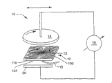
Referring to each figure, these figure have shown embodiments of the present invention, now are illustrated.For example, Fig. 1 has schematically shown ECMD system 10.FIxed abrasive article 12 is provided.System 10 allow grinding tool 12 be in can with the surperficial position contacting of semiconductor wafer 14.By charge pipe 18 electroplate liquid of metal ion is delivered to grinding tool 12.Electroplate liquid is carried by groove on grinding tool 12 or slit 13, arrives the surface of semiconductor wafer 14 then.Electroplate liquid is as plating metal to semiconductor wafer 14 lip-deep metal ion sources.The variable potential difference 16 that utilization applies in grinding tool 12 and both sides, semiconductor wafer 14 interface, metal deposits on semiconductor wafer 14 surfaces from electroplate liquid.The surface of semiconductor wafer 14 has metal seed layer etc. usually, and just there is electric conductivity on its surface like this, and can be used as negative electrode.Usually anode 20 is placed suitable position, make grinding tool 12 be between anode 20 and the wafer/negative electrode 14, positive potential and metal ion source are provided simultaneously.
The electronegative attracted by surfaces of semiconductor wafer the metal ion in the electroplate liquid, electroplate liquid then flows into from charge pipe 18, flow to by the slit in the grinding tool 12 13 on the exposed face of semiconductor wafer 14, by applying potential difference, plate metal on the surface of wafer, preferably be electroplated onto in through hole and/or the groove.For ease of polishing, grinding tool 12 comprises polishing layer 100, and grinding tool 12 can rotate relatively each other with wafer semiconductor 14.The means that grinding tool 12 and/or 14 whiles of semiconductor wafer can also be provided or move face-to-face in regular turn.
Can adopt grinding tool 12 for example or one independently the baffle (not shown) hide some regional method of wafer and the metal of semiconductor wafer 14 is electroplated controlled.During electroplating,, generally require semiconductor wafer 14 and grinding tool 12 during applying electrolyte, to keep in touch mutually with the method for grinding tool 12 as baffle.In this way, the semiconductor wafer that geometry the determined 14 surperficial appointed areas that electroplating current and electroplating solution arrive by slit 13 by slit 13, the plating of metal mainly occurs in the zone that the wafer surface that is exposed to electroplate liquid does not add covering.During plated metal, grinding tool 12 and semiconductor wafer 14 can be done relative motion, all are rotated as one of semiconductor wafer 14 and/or grinding tool 12 or both.Grinding tool 12 moves with respect to semiconductor wafer 14 surfaces and helps the polishing of the first metal that has deposited.
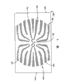
Fig. 2 is the exploded view according to a fixed abrasive article 12 of embodiment of the present invention structure.Grinding tool 12 comprises the polishing layer 100 with first surface 102.Layer 100 can be supported by supporting pad 118 (see figure 4)s that at least one stiffener layer 128 and resilient element 126 are formed.Layer 100,128 and 126 is bonded to each other with the adhesive that for example is suitable for usually.First surface 102 is the working face of polishing layer 100.Like this, just have the grinding texture on the first surface 102, will produce polishing force the surface of semiconductor wafer 14.Texture on polishing layer 100 first surfaces 102 can comprise the surface texture of irregular surface texture and rule.Can provide support with 118 pairs of polishing layers 100 of supporting pad, also can use other method for supporting, and regard as within the scope of the present invention.
Referring to Fig. 3, polishing layer 100 comprises first groove 104, and this groove extends to the second surface (not shown) opposing with first from first surface 102 by polishing layer 100.Polishing layer 100 comprises many first grooves 104 usually, and each first groove 104 extends to till the position near one of both sides 108 all from the zone (being typically expressed as 106) in bosom.As shown in the figure, every first groove 104 all has one along the length of this groove and the width " w " that changes.Every first groove 104 width, foot make and allow suitable zone is exposed to electroplate liquid on the semiconductor wafer 14, thereby conducting metal is deposited with the amount that is suitable for forming circuit.Groove 104 has the near-end of the most close center 106 and extends to the far-end of polishing layer frontside edge 108, is that last groove part 110 finishes at narrow groove part.The end groove part can make excessive electroplate liquid discharge from the interface of 14 of grinding tool 12 and semiconductor wafers.
Texture form on the first surface 102 of polishing layer 100 is suitable for semiconductor wafer 14 surfaces are polished.The texture of first surface 102 comprises jut and sunk part, and wherein jut contains adhesive material at least.Can be with grinding-material, for example abrasive particle is fixed or is dispersed in the adhesive of first surface 102.The professional person knows that polishing layer and grinding tool can have various structures.For example, the structure of above-mentioned groove 104 can be different from as shown in the figure and extend to the side as described above.A kind of alternative form is unique groove, or a series of or multi-series is arranged in the slit of polishing layer, its objective is electroplate liquid is transported on the exposed face of semiconductor wafer.The structure in slit can be varied, and the slit that the grinding tool surface can comprise any amount, arrange with following any way is as circular array, linear array shape etc.The present invention does not plan polishing layer, grain surface or groove are limited to any specific textural.
Polishing layer can be made by the adhesive precursor material, is polymeric material as resin, as liquid or semisolid material preparation, is solidified then earlier, forms the curing materials that is applicable to semiconductor wafer polishing.The material that is applicable to the polishing layer manufacturing comprises organic adhesive precursor, but is flow regime at the beginning, but is transformed into the adhesive of curing when grinding tool is made.The adhesive that solidifies be solid, can not flow regime.Adhesive can form by thermoplastic or by material (as thermosetting resin) that can be crosslinked.Within the scope of the present invention, it can also be formed by the mixture of thermoplastic adhesives and crosslinked adhesive.Among the process of making grinding tool, adhesive precursor is exposed to its curing of suitable condition under suitable condition.But for the adhesive precursor of crosslinkable or chain growth, but the following initiated polymerization or solidify of the effect that adhesive precursor is exposed to the suitable energy to form adhesive.Therefore after curing, adhesive precursor is transformed into adhesive.
Adhesive precursor can be the organic matter that crosslinked and/or chain growth can take place.These adhesive precursors both can be the resins of condensation curable, but also can be the resins of addition polymerization.But the addition polymerization polyester can be ethylenically unsaturated monomers and/or oligomer.But the available crosslinkable or the material of chain growth are for instance, comprise amino resin, urethane resin, epoxy resin, acrylic resin, propylene acidifying isocyanuric acid ester resin, urea-formaldehyde resins, isocyanuric acid ester resin, propylene acidifying urethane resin, propylene acidifying epoxy resin c and their mixture of phenolic resins, BMI, vinyl ether resin, tool α, β unsaturated carbonyl side group.
Also can use the condensation curable resin.Phenolic resins because of its heat endurance height, the source is wide, cost is low and easy operating is widely used as abrasive article binder.Phenolic resins, phenol-formaldehyde A and novolac that two kinds of types are arranged.The formaldehyde of phenol-formaldehyde A and the mol ratio of phenolic aldehyde are more than or equal to 1, usually at .5: between 1.0 to 3.0: 1.0.The formaldehyde of novolac and the mol ratio of phenolic aldehyde are less than 1 to 1.Market phenolic resins on sale comprises those " Durez " from Occidental Chemicals company, " Varcum " for instance, from " Resinox " of Monsanto company, from " Arofene " of AshlandChemical company with from the product of " Arotap " of Ashland Chemical company.
Also can use latex resin, use separately or with other mixed with resin.For example, latex resin can mix with phenolic resins, and comprises acrylonitrile butadiene emulsion, acrylic emulsion, butadiene emulsion, butadiene styrene emulsion and their mixture.These latex resin markets are on sale, and the source is different, comprising: " Rhoplex " and " Acrylsol " that can buy from Rohm and Hass, from AirProducts﹠amp; " Flexcryl " of Chemicals Co., Ltd and " Valtac ", from " Synthemul " and " Tylac " of ReicholdChemicals company, from " Hycar " and " Goodrite " of B.F.Goodrich company, from " Chemigum " of Gooyear Tire and Rubber company, from " Neocryl " of ICI company, from " Butafon " of BASF AG with from " Res " of UnionCarbide company.
Epoxy resin has ethylene oxide group, can polymerization by open loop.Such epoxy resin comprises monomeric form epoxy resin and polymer form epoxy resin.The trunk of these resins and substituent character can be very different.For example, trunk links to each other with any kind epoxy resin usually, and the substituting group on it can be any group that does not have at room temperature can give birth to the oxirane environment-development reactive hydrogen atom of reaction.The representational example of acceptable substituting group comprises halogen, ester group, ether, sulfonate group, silylation, nitro and phosphate-based.Some preferred epoxy resins examples, comprise 2, two [4-(2, the 3-ethoxy third oxygen)-phenyl] propane (bisphenol-A glycidyl ether) of 2-] and market material on sale: from " Epon 828 " of Shell Chemical company, " Epon 1004 " and " Epon 1001F " with from " DER-331 ", " DER-332 " and " DER-334 " of Dow Chemical company.Other epoxy resin that are suitable for comprise the glycidyl ether (as " DEN-431 " and " DEN-428 ") of phenol formaldehyde novolac.
The unsaturated adhesive precursor of ethylenic can comprise have α, the aminoplast monomer of β unsaturated carbonyl side group or oligomer, ethylenically unsaturated monomers or oligomer, propylene acidifying isocyanurate monomers, propylene acidifying urethanes oligomer, propylene acidifying epoxy monomer or oligomer, ethylenically unsaturated monomers or diluent, acrylate dispersant or their mixture.All have at least one α, β unsaturated carbonyl side group on each molecule of aminoplast binder precursor or the oligomer.These materials are at United States Patent (USP) 4,904, detailed description are arranged in 440 and 5,236,472, with reference to being incorporated into this.Ethylenically unsaturated monomers or oligomer can be simple function, difunctionality, trifunctional, four senses or degree of functionality even higher." acrylate " this speech comprises acrylate and methacrylate.
The unsaturated adhesive precursor of ethylenic that is suitable for comprises haplotype compound and the aggretion type compound that contains following atom: carbon, hydrogen, oxygen, or also have nitrogen and halogen.Oxygen or nitrogen-atoms or this two kinds of atoms are present in usually among ether, ester, urethanes, acid amides or urea groups.The molecular weight of ethylenically unsaturated compounds is preferably less than 4,000, and preferably by containing aliphatic monohydroxy or aliphatic polyhydric compound and unsaturated carboxylic acid, as esters that reaction produced such as acrylic acid, methacrylic acid, itaconic acid, crotonic acid, iso-crotonic acid, maleic acids.The representative example of ethylenically unsaturated monomers comprises methyl methacrylate, ethyl acrylate, styrene, diethylbenzene, hydroxyethyl acrylate, the methacrylic acid hydroxyethyl ester, the acrylic acid hydroxypropyl ester, hydroxypropyl methacrylate, hydroxybutyl acrylate, the hydroxyethyl methacrylate butyl ester, ethyltoluene, glycol diacrylate, polyethyleneglycol diacrylate, ethylene glycol dimethacrylate, hexanediyl ester, triethylene glycol diacrylate, trimethyl alcohol propane triacrylate, glycerol tri-acrylate, pentaerythritol triacrylate, pentaerythritol acrylate trimethyl, tetramethylol methane tetraacrylate and pentaerythrite tetramethyl acrylate.Other ethylenic unsaturated-resins comprise monoene propyl group, polyenoid propyl group and the many methacrylic esters and the acid amides of carboxylic acid, as diallyl phthalate, diallyl adipate and N, and N-diallyl adipamide.Other nitrogenous compounds comprise three (2-acrylic-oxygen ethyl) isocyanuric acid ester, 1,3,5-three (2-methylpropenyl oxygen ethyl)-s-triazine, acrylamide, Methacrylamide, N methacrylamide, N,N-DMAA, N-ethyl pyrrolidone and N-ethylpiperidine ketone.
Have the isocyanurate derivative of at least one pendant acrylate groups and isocyanate derivates at United States Patent (USP) 4,652, detailed description is arranged in 274, with reference to being incorporated into this with at least one pendant acrylate groups.Preferred isocyurnate material has the triacrylate of three (ethoxy) isocyanuric acid ester.
Propylene acidifying urethanes is the acrylate that esters of hydroxy terminated isocyanate is extended polyester or polyethers.Commercially available propylene acidifying urethanes comprises " UVITHANE782 ", " CMD 6600 " from UCB Radcure Specialties company, " CMD 8400 " and " CMD8805 " from Morton Chemical company for instance.Propylene acidifying epoxides is the acrylate of epoxy resin, as the acrylate of bisphenol A epoxide resin.Commercially available propylene acidifying epoxides comprises " CMD3500 ", " CMD3600 " and " CMD3700 " from UCBRadcure Specialties company for instance.
Other details of relevant acrylate dispersant can find among 252 (Follensbee) from United States Patent (USP) 5,378, and this patent reference is incorporated into this.
Within the scope of the present invention, can also in adhesive precursor, use partially polymerized ethylenically unsaturated monomers.For example acrylate monomer can be partially polymerized and be added in the slurry.Should be controlled the partially polymerized degree of polymerization,, thereby can be applied the formation grinding tool with made slurry in order that the viscosity of the partially polymerized ethylenically unsaturated monomers that is produced is unlikely too high.Acrylate monomer that can be partially polymerized comprises Isooctyl acrylate monomer for instance.Within the scope of the present invention, but can also use the mixture of the adhesive of partially polymerized ethylenically unsaturated monomers and another kind of ethylenically unsaturated monomers and/or condensationization.
Acrylic ester adhesive and epoxy adhesive have been used in the present invention.The acrylic ester adhesive that is suitable for comprises 2-phenoxyethyl acrylate, propoxylation 2 neopentylglycol diacrylates, polyethyleneglycol diacrylate, pentaerythritol triacrylate, 2-2 (ethoxy ethoxy) ethyl acrylate etc.The epoxy adhesive that is suitable for comprises bisphenol-A diglycidyl ether, 1,4-butanediol diglycidyl ether etc.Epoxy adhesive can with the situation of amine, amide compound or acid catalyzed polymerisation under solidify.
Abrasive coating of the present invention can comprise some additives, as abrasive surface modifier, coupling agent, plasticizer, filler, swelling agent, fiber, antistatic additive, initator, suspending agent, sensitising agent, lubricant, wetting agent, surfactant, pigment, dyestuff and ultra-violet stabilizer etc.Consumption to these materials will be selected, so that produce the performance that needs.
Abrasive coating can also comprise plasticizer.Generally speaking, the interpolation of plasticizer can increase the weathering property of abrasive coating, makes adhesive whole softening.The example of plasticizer comprises polyvinyl chloride, DBP, phthalandione alkyl benzyl ester, polyvinyl acetate, polyvinyl alcohol, cellulose esters, phthalic acid ester, silicone oil, adipate ester and sebacate, polyalcohol and derivative thereof, t-butyl phenyl diphenyl phosphoester, tricresyl phosphate, castor oil and their mixture etc.
Abrasive coating also maybe can comprise a kind of filler makes the coating malleableize.On the contrary, exist under the situation of suitable filler and quantity thereof at some, filler can increase the weathering property of abrasive coating.Filler is a kind of specific material, and the size ranges of this material granule is at the 0.1-50 micron, typically between the 1-30 micron.Can be used for filler example of the present invention comprises: metal carbonate (calcium carbonate (chalk, calcite, plaster, calcareous tufa, marble and lime stone), miemite, sodium carbonate, magnesium carbonate), silica is (as quartz, bead, glass envelope and glass fibre), silicate is (as talcum, clay (imvite), feldspar, mica, calcium silicates, sodium aluminosilicate, sodium metasilicate), metal sulfate is (as calcium sulfate, barium sulfate, sodium sulphate, aluminum sodium sulfate, aluminum sulfate), gypsum, cinnabar, wood powder, aluminum trihydrate, carbon black, metal oxide is (as calcium oxide (lime), aluminium oxide, tin oxide, titanium oxide) and metal sulphite (as calcium sulfite), thermoplastic is (as Merlon, polyimide, polyester, polyethylene, polysulfones, polystyrene, the acrylonitrile-butadiene-styrene (ABS) block copolymer, polypropylene, acetal polymer, polyurethane, the nylon particle) and thermosets (steep as phenol, the phenol pearl, polyurethane foam material etc.).Filler can also be a salt, as halogen.The example of halogen comprises that sodium chloride, potassium ice crystal close, receive ice crystal, ice crystal ammonium stone, potassium tetrafluoroborate, sodium tetrafluoroborate, silica, potassium chloride, magnesium chloride.The example of metal filler comprises tin, lead, barium, cobalt, antimony, chromium, iron, titanium.Other various fillers comprise sulphur, organic sulfur compound, graphite and metal sulfide.The example of above-mentioned filler is representational filler example, and does not mean that and comprise all fillers.
The example of antistatic additive comprises graphite, carbon black, vanadium oxide, conducting polymer, wetting agent etc.These antistatic additive are disclosed in United States Patent (USP) 5,061, in 294,5,137,542 and 5,203,884, with reference to being incorporated into this.
Also can comprise curing agent in the adhesive precursor.Curing agent is to help to cause and finish polymerization or thereby cross-linking process makes adhesive precursor be transformed into the material of adhesive.Curing agent one speech comprises initator, photoinduction agent, catalyst and activator.The consumption of curing agent and type depend on the chemical property of adhesive precursor to a great extent.
When the first surface 102 of polishing layer 100 contained abrasive material, this abrasive material can be selected from various materials.For example, inorganic abradant and/or organic group material are applicable to grinding tool.Inorganic abradant can be divided into hard inorganic abradant (being that Mohs' hardness is greater than 8) and soft inorganic abradant (being that Mohs' hardness is less than 8).Traditional hard grind material example comprise fused alumina, heat treatment aluminium oxide, white fused aluminum oxide,, black silicon carbide, green silicon carbide, titanium diboride, boron carbide, tungsten carbide, titanium carbide, diamond, cubic boron nitride, garnet, fused alumina zirconia, sol gel abrasive etc.The example of sol gel abrasive can be at United States Patent (USP) 4,314, finds in 827,4,623,364,4,744,802,4,770,671,4,881,951, with reference to being incorporated into this.
Traditional softer inorganic abradant comprises silica, iron oxide, chromium oxide, cerium oxide, zirconia, titanium oxide, silicate and tin oxide.Also have the example of some buffing material to comprise that metal carbonate is (as the Paris white chalk, calcite, plaster, calcareous tufa, marble and lime stone), miemite, sodium carbonate, magnesium carbonate), silica is (as quartz, bead, glass envelope and glass fibre) silicate is (as talcum, the clay imvite, feldspar, mica, calcium silicates, sodium metasilicate, sodium metasilicate), the metal sulfate ester is (as calcium sulfate, barium sulfate, sodium sulphate, aluminum sodium sulfate, aluminum sulfate), gypsum, cinnabar, wood powder, aluminum trihydrate, carbon black, metal oxide is (as calcium oxide (lime), aluminium oxide, tin oxide, titanium oxide and metal sulphite (as calcium sulfite), metal material (tin, plumbous, copper etc.) or the like.
Plastic abrasive can be made by following thermoplastic: as Merlon, polyimide, polyester, polyethylene, polysulfones, polystyrene, acrylonitrile-butadiene-styrene (ABS) block copolymer, polypropylene, acetal polymer, polyvinyl chloride, polyurethane, polyureas, nylon and their mixture.Generally speaking, be used for thermoplastic polymer of the present invention and generally can have high melting temperature or good hear resistance.Several production thermoplasticity mill methods are arranged.A kind of method is that the thermoplastic polymer extruding is generated long section, and the section that will grow then cuts into the length that needs.In addition, thermoplastic polymer can be molded as the particle that needs shape and size.This moulding technology can be extrusion molding or injection moulding.Plastic abrasive particles can be made with cross-linked polymer.The example of cross-linked polymer comprises: phenolic resins, amino resin, urethane resin, epoxy resin, maleic amide-formaldehyde, methacrylate resin, propylene acidifying isocyanuric acid resin, urea-formaldehyde resins, isocyanuric acid resin, propylene acidifying urethane resin, propylene acidifying epoxy resin and their mixture.These cross-linked polymers be can make, crush and sieve and the granularity of needs and the particle of size distribution become.Thermosetting and thermoplastic polymer abrasive particle can be made with method of emulsion polymerization.
Abrasive particle can also comprise the mixture of two or more different abrasive particles.In the mixture of two or more different abrasive particles, various abrasive particles can have identical particle mean size, or opposite, and each abrasive particle can have different particle mean sizes.Again on the other hand, can be with the mixture of inorganic abrasive particle and organic abrasive particle.
Can handle abrasive particle and form face coat in the above.Bonding force between the known adhesive that can improve in abrasive particle and the grinding tool of face coat.In addition, face coat can also improve the dispersibility of abrasive particle in adhesive precursor.In addition, face coat can change and improve the grinding performance of the abrasive particle that is produced.
In one embodiment, polishing layer comprises the acrylic ester adhesive of the curing made from adhesive precursor, comprises two kinds of acrylate monomers, dispersant, initator and a kind of alumina abrasive grain in this adhesive precursor.Commercially available from being positioned at Exton, the acrylate of the Startomer company of PA is third oxidation-2-neopentylglycol diacrylate of (1) commodity " Sartomer SR9003 " by name and the 2-benzene oxygen ethyl propylene acid esters of (2) commodity " Sartomer SR339 " by name.In adhesive precursor, add dispersant, as be positioned at Wallingford, the dispersant of the commodity that the BYK Chemie company of CT sells " Dysperbyk D111 " by name.For initiated polymerization, there is initator in the adhesive, as can be from being positioned at Tarrytown, the initator that is called " Irgacure 819 " that the Ciba Giegy company of NY buys.Can also in adhesive precursor, add alumina abrasive grain so that give finished particle with abrasiveness.A kind of such abrasive particle is can be from being positioned at Penn Yan, " Tizox " alpha-aluminium oxide that the Ferro company of NY buys.
Adhesive can be formed the abrasive composite of many accurate shapes, each composition all comprises the abrasive particle that is fixed and dispersed within the adhesive.Can after other factors that the situation of having considered to want polished surface, the required hardness of available abrasive material and professional person are understood, abrasive particle be selected according to customer requirements.In general, the Mohs' hardness of abrasive material will be in about 2-10 scope.When the conductive material that is used on the polishing semiconductor workpiece, the abrasive action that abrasive particle rose of hardness in this scope can reach requirement.
Referring to Fig. 4, this illustrates a cross section of grinding tool 12 of the present invention.The first surface 102 of polishing layer 100 comprises the fixing three-dimensional abrasive complex 103 that accurate shape is arranged that sticks on the available supporting layer 112.These three-dimensional abrasive complexs 103 provide the texture that is suitable for polishing operation for first surface 102.Sticking with glue agent layer 115 makes the second surface 114 of polishing layer 100 and first backing surface 116 bonding.The adhesive that is applicable to this adhesive layer 115 comprises that the pressure-sensitive adhesive (PSA) of the Minnesota Mining and Manufacturing company (" 3M ") of MN is as polyolefin, polyacrylate or polyurethane PSAs available from being positioned at St.Paul.Specifically, commodity " 3M 9671LE " or " 3M 9471LE " by name have been successfully applied to the production of grinding tool 12 available from the PSAs of 3M company.Backing 118 comprise two-layer at least 126 and 128 and with the second opposing backing surface 124 of polishing layer.In the embodiment shown, backing 118 has individual resilient element 126, also has a stiffener layer 128 to be inserted between resilient element 126 and the fixing three-dimensional abrasive complex 103.The modulus (i.e. Young's modulus on the material plane direction) of the modulus of resilient element 126 (promptly in the Young's modulus on the thickness direction) specific rigidity element layer 128 is few about 25%, even few 50%.The Young's modulus of stiffener layer 128 is at least 100Mpa.The Young's modulus of resilient element is generally less than 50MPa.
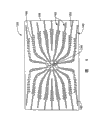
Referring to Fig. 5, the stiffener layer 128 of backing 118 comprises second groove 130, and groove 130 is from being designated as 132 core extension, near edge 134 end that arrive stiffener layer 128 usually.Every second groove 130 comprises a series of tap hole 140, and they are arranged with perceptible stepped form, extends on whole stiffener layer 128, aims at those first grooves 104 on the polishing layer 100 and common the extension.As shown in Figure 6, the resilient element 126 of backing 118 also comprises many second grooves 142, begins to extend from 144 the core of being designated as usually of stiffener layer 128, finishes near the edge 146.Every second groove 142 comprises a series of tap hole 148, extends on whole elastic element layer 126, aims at the second groove tap hole 140 of stiffener layer 128 and common the extension.The tap hole 148 of the groove 142 on resilient element 126 is connected with each other along the groove assembly 150 of elongation.Stiffener layer 128 is between resilient element 126 and polishing layer 100, and the PSA with being suitable for is bonded together these three layers mutually as above-mentioned commercially available 3M 9671LE and 3M 9471LE.
Second groove, 142 extensions aligned with each other and common of second groove 130 of stiffener layer 128 and resilient element 126, the tap hole 148 of tap hole 140 alignment indentation 142 of groove 130 like this, so that allow fluid, tuck in by backing 118 as electrolysis and unhinderedly to flow out.The size in tap hole 140 and 148 holes can be identical.As mentioned above, the present invention is not limited to a particular embodiment backing 118.In addition, groove 130 and 142 structure are not got rid of other design and structure only as an example.Although shown tap hole 140 and 148 is a rectangle, the professional person can understand that tap hole can be circle, semicircle, triangle or other shapes, and can have virtually any size.Backing can comprise aforesaid layer 128 and 126, also can be an individual layer, the invention is intended to and will all these structures be included.
In the grinding tool 12 that assembles, polishing layer 100 and supporting pad 118 are fixing or otherwise be connected, and make that first groove 104 is just aimed at second groove 130 on the stiffener layer 128, and all tap holes 140 all are on the lateral boundaries of first groove 104.In this way, such as will be described in detail, thus second groove 130 of second groove 130 of tap hole 140, stiffener layer 128 and resilient element 126 conduit that connects grinding tool 12 that provides all aligned with each other.The configuration of first groove 104 and second groove 130 and 142 is corresponding each other, thereby the first surface 102 of veined polishing layer is in outside the sight line.
Referring to Fig. 7, the surface that includes the silicon wafer of metal seed layer on first surface 102 and the exposed face usually contacts.As previously mentioned, grinding tool 12 links to each other with the anode of ECMD lathe, and the lathe negative electrode is generally played on the exposed metalization of semiconductor wafer 14 surface.
The anode (not shown) generally is positioned at below the supporting pad 118, near the position of grinding tool 12 minimum surfaces 124.Groove width W can allow metal deposition on the surface of semiconductor wafer 14, and major sedimentary enters in groove and the through hole 152, makes the deposition on first table 102 of the other places of wafer surface and grinding tool 12 the least possible simultaneously.
The width of the groove 104 that a structure of grain surface provides, be this that make groove 104 specific rigidity element layers 128 portal 140 and the tap hole 148 of resilient element wide.Observer " a " is positioned at the anode place near surface 124, watches by tap hole 140, tap hole 148 and first groove 104 simultaneously, can't see and semiconductor wafer 14 first surface in contact 102.In other words, aforementioned apertures 140 and 148 and the structure of groove 104 and relative size select to such an extent that make interface contact between first surface 102 and the semiconductor wafer 14 outside the observer visual field, 0.2mm is for example arranged, and 0.5mm is generally arranged.
Under the above-mentioned arrangement situation of each parts, molten the tucking in by tap hole 140, tap hole 148 and first groove 104 of electrolyte applies on the surface that is applied to semiconductor wafer workpiece.Other zones of wafer surface then intercept with the contact of the surface between wafer and the first surface 102.For example in ECMD technology, grinding tool of the present invention can be used at first help metal to be deposited on the wafer surface, polishes or reduce the sedimentation rate of conductive material then.The ECMD process can be at United States Patent (USP) NO.6, carries out on the described equipment of 176,992 (Talieh).Comprise as available business machine in the ECMD process described here and to derive from Nu Tool, Inc, ofMolpitas, " NuTool2000 " lathe of Calofornia.Grinding tool of the present invention can be used for this equipment.
ECDM technology applies a negative potential to the negative electrode that links to each other with wafer, and the anode that links to each other with grinding tool or polishing plate is applied a positive potential when operation.Led to electric current in two electrodes after, the metal ion in the electrolyte solution just begins to deposit on the wafer surface.This moment, metal ion attracted to the surface of wafer because of the negative potential that is applied to negative electrode.Grinding tool is positioned on the surface of wafer, together with the polishing of grinding tool or friction effect stoped metal be positioned on the wafer surface by outside or the zone accumulation metal of phase line.
In the second stage of operation, if desired, wafer surface can be carried out cleaning, can further polish with grinding tool under the no current situation or under the pole reversal situation with electric current.Can use conventional polishing slurries to carry out ground/polished, but this is used less.
The structure of grinding tool of the present invention provides the flow channel that meets above-mentioned " sight line " standard, can make electrolyte solution flow by grinding tool, deposit metal on the described zone of workpiece, and avoided metal depositing on the first surface 102 of grinding layer 100 and on the wafer surface region beyond through hole and the groove as far as possible.
In another embodiment of grinding tool of the present invention, an additional resilient element can be fixed with supporting pad 118 or link to each other.In this embodiment, the additional rigidity layer (as Merlon) of material can link to each other with grinding tool 12, resilient element 126 is located between the similar or identical resilient element like this, these resilient element have essentially identical running through wherein of form and the tap hole of extension, the electrolyte stream that allows cross grinding tool, as do general discussion at this.
The professional person can understand that grinding tool of the present invention can have the flow groove that runs through grinding tool, and the structure of this groove is with described above different, and the present invention is not limited the structure of above-mentioned flow groove.More generally, the present invention relates to have the grinding tool of the polishing layer of texture, this polishing layer comprises and starts from first surface, passes veined polishing layer and extend to first groove of second surface, the second surface of veined polishing layer contacts with backing, this backing comprises second groove that extends through backing with first groove jointly, first groove and second groove are on a sight line of passing grinding tool, and therefore the first surface of veined polishing layer is beyond sight line.
The present invention can use in the method that conductive material is deposited to surface of semiconductor workpiece.In this method, semiconductor workpiece is placed on the place near anode as negative electrode, is applying under the voltage condition like this, and electroplate liquid can be set up between anode and semiconductor wafer surface and electrically contact.A grinding tool as mentioned above, is placed on close anode place between anode and the negative electrode, thereby the abradant surface of grinding tool is contacted with the exposed face of semiconductor wafer.Antianode applies first current potential, target applies second current potential, electric conductivity electrolysis liquid is flowed to semiconductor wafer, and first and second grooves by grinding tool arrive the zone that surface of semiconductor workpiece needs electro-deposition, there metal are electroplated onto from electrolyte on the surface of wafer.The surface of grinding tool is used for assisting conductive material is deposited to the zone of surface of the work appointment.Then, the grain surface of grinding tool can be used for the metal of surface of semiconductor workpiece deposition is polished/polishes.
Decide with concrete polishing purposes, the active force on the interface between veined first surface 102 and semiconductor wafer 14 surfaces is often very little, usually less than 1 pound of (being 0.45kg), weight of a 200mm wafer in this way.
Use following non-limiting embodiment, can further understand the more detailed situation of the better embodiment of the present invention.
Embodiment
General procedure A (preparation of grinding tool)
Polypropylene molds is made by carry out the polypropylene casting on metal mother, and this master mold has the casting face of being made up of many adjacent posts.The mould of gained comprises many holes that are column.The distribution of post is such: the bottom of adjacent post is not more than 740 microns (0.029 inches) each other apart, and the height of each post is about 40 microns.13 lines/centimetre describe array of post of having an appointment.With covering type pressure sensitive adhesive tape mould is fixed on the metal support plate.Prepare adhesive precursor with each component described in the embodiment.With high shear mixer with the precursor mixing.Filter with 60 μ m or 80 μ m filters this precursor then.
General procedure B (the last formation of abrasive material)
On polishing layer, cut out some grooves according to the embodiment preparation.Divide several steps to prepare again to have different size and geometry groove subsequently which floor, as carbonic ester or sponge layer.The cutting processing of this groove can adopt water spray or laser ablation process.Can also use traditional cross cutting instrument or the equipment of sharp cutter is arranged.In the present embodiment, by being positioned at Somerset, the Laser Machining Co., Ltd of WI contracts the laser cutting groove.After cutting groove, with each layer alignment and lamination in addition.Then this product alignment is bonded on the platen of ECMD lathe.
Embodiment 1
Prepare adhesive precursor by the following method: can be from being positioned at Exton with 10g, third oxidation-2-the neopentylglycol diacrylate of the commodity that the Sartomer company of PA buys " Sartomer SR9003 " by name, 15g commodity " Sartomer SR339 " by name are (equally from Exton, the Sartomer company of PA) 2-benzene oxygen ethyl propylene acid esters, 2.53g dispersant (can be from being positioned at Wallingford, the commodity that the BYK Chemie company of CT buys are called Disperbyk 111), 0.27g initator is (as can be from being positioned at Tarrytown, the Irgacure 819 that the Ciba Giegy company of NY buys) and 72g aluminium oxide (can from being positioned at Penn Yan, " Tizox " alpha-aluminium oxide that the Ferro company of NY buys) mix.After the hx adhesive precursor mixed, be coated with scraper plate in the cavity of mould, and contained binder paste contacts in the cavity of the polyester film backing that will play priming paint and mould.The laboratory of the sub-assembly of gained by the bench top buied from Chem Instruments company is with laminating machine (model is #001998).Continuously sub-assembly is being fed under the pressure of about 280-560Pa between two rubber rollers, feeding speed is set at about 61-213cm/min (2-7 feet per minute clock).One quartz plate is placed on the sub-assembly.Ultraviolet ray " V " the shape bulb that the mould that will have backing and a binder paste can be buied from Fusion System Co., Ltd two ultraviolet lamps (can buy from Amecian Ultraviolet company) that ooze iron or two below by, this sub-assembly is solidified, and all operates with 157.5Watt/cm (400 watts/inch) under two kinds of lamp situations.The speed of passing through of sub-assembly remains between 4.6-13.7 rice/minute (15-45 feet per minute clock), and passes through twice under the UV light source.Then the fixing grinding tool of structure that is produced is taken out from polypropylene molds.
Embodiment 2
A kind of preparation of adhesive precursor is: about 50g epoxy resin (available from being positioned at St.Paul, the 3M Scotch-Weld 1838-L (Part A) of the Minnesota Mining and Manufacturing company of MN) is mixed with the another kind of epoxy curing agent of 50g (3M Scotch-Weld 1838-L (Part B)).After this adhesive precursor mixed, be coated with scraper plate in the cavity of progressive die tool, and contained binder paste contacts in the cavity of the polyester film backing that will play priming paint and mould.The laminating machine (model be #001998) of sub-assembly by using then from the bench top laboratory that ChemInstruments company buys.Continuously sub-assembly is being fed between two rubber rollers under the pressure of about 280-560Pa, feeding speed is set at about 61-213cm/min (2-7 feet per minute clock).Sub-assembly was left standstill 15 hours, and then that the structure of gained is fixing grinding tool takes out from polypropylene molds.
Though better embodiment of the present invention has been done detailed description, the professional person can understand, can under the scope of the invention and the spirit situation of (as can be seen in the claims) to described embodiment change or improvement.
Claims (20)
1. one kind is applicable to that conductive material deposits and the grinding tool of machine glazed finish, and this grinding tool comprises:
Polishing layer with grain surface, this polishing layer comprise adhesive and with the opposing second surface of grain surface, polishing layer also comprises first groove that passes this layer and extend;
Backing with first and second backing surfaces, first backing surface contacts with the second surface of polishing layer, and this backing comprises and common second groove that extends of first groove, and since first backing surface, passes backing and extend to the second backing surface;
First groove and second groove are making the grain surface of polishing layer beyond sight line on the relative size.
2. the described grinding tool of claim 1 is characterized in that, comprises many abrasive composite on the described grain surface.
3. the described grinding tool of claim 2 is characterized in that, described abrasive composite is the abrasive composite that accurate shape is arranged.
4. the described grinding tool of claim 1 is characterized in that, first groove and second groove make the grain surface of polishing layer 0.2mm at least beyond the sight line on relative size.
5. the described grinding tool of claim 1 is characterized in that, the first surface of described grain surface also comprises the abrasive particle that is fixed in the adhesive.
6. the described grinding tool of claim 1, it is characterized in that, described polishing layer comprises many first grooves, described grain surface comprises a core and at least one edge, each first groove divides beginning from central division, in the zone that extends on the grain surface on grain surface near at least one edge.
7. the described grinding tool of claim 1 is characterized in that, first groove has one along the length of this groove and the width that changes.
8. the described grinding tool of claim 1 is characterized in that, described backing comprises first back sheet and second back sheet, and first back sheet is near the second surface of polishing layer, and first and second back sheets comprise different materials.
9. the described grinding tool of claim 8 is characterized in that, the hardness of the first back sheet material is greater than the hardness of the second back sheet material.
10. the described grinding tool of claim 9 is characterized in that, first back sheet is a Merlon, and second back sheet is a polymer foams.
11. the described grinding tool of claim 1 is characterized in that, second groove comprises many apertures that backing extends that pass, and these apertures are aimed at first groove of polishing layer usually.
12. the described grinding tool of claim 11 is characterized in that, the size of these apertures is different separately.
13. the described grinding tool of claim 11 is characterized in that, these apertures be shaped as rectangle.
14. the described grinding tool of claim 1, it is characterized in that, described backing comprises first back sheet, second back sheet and the 3rd back sheet, first back sheet is near the second surface that the texture abrasive material is arranged, second back sheet is between the first and the 3rd back sheet, and first and second back sheets comprise different materials.
15. the described grinding tool of claim 14 is characterized in that the hardness of the first back sheet material is greater than the hardness of the second back sheet material.
16. the described grinding tool of claim 14 is characterized in that, the first and the 3rd back sheet is an identical materials.
17. the described grinding tool of claim 14 is characterized in that, the first and the 3rd back sheet is a Merlon, and second back sheet is a polymer foams.
18. the described grinding tool of claim 14 is characterized in that, second groove comprises many apertures that first, second and the 3rd back sheet extend that pass, and these apertures usually and first groove alignment of polishing layer.
19. the described grinding tool of claim 18 is characterized in that, the size difference of these apertures.
20. the described grinding tool of claim 18 is characterized in that, these apertures be shaped as rectangle.
Applications Claiming Priority (2)
| Application Number | Priority Date | Filing Date | Title |
|---|---|---|---|
| US10/021,161 US6838149B2 (en) | 2001-12-13 | 2001-12-13 | Abrasive article for the deposition and polishing of a conductive material |
| US10/021,161 | 2001-12-13 |
Publications (2)
| Publication Number | Publication Date |
|---|---|
| CN1604834A CN1604834A (en) | 2005-04-06 |
| CN100450716C true CN100450716C (en) | 2009-01-14 |
Family
ID=21802689
Family Applications (1)
| Application Number | Title | Priority Date | Filing Date |
|---|---|---|---|
| CNB02825001XA Expired - Fee Related CN100450716C (en) | 2001-12-13 | 2002-10-15 | Abrasive article for the deposition and polishing of a conductive material |
Country Status (10)
| Country | Link |
|---|---|
| US (1) | US6838149B2 (en) |
| EP (1) | EP1465750A1 (en) |
| JP (1) | JP4405805B2 (en) |
| KR (1) | KR100926198B1 (en) |
| CN (1) | CN100450716C (en) |
| AU (1) | AU2002335025A1 (en) |
| IL (1) | IL161977A0 (en) |
| MY (1) | MY138955A (en) |
| TW (1) | TWI229153B (en) |
| WO (1) | WO2003051577A1 (en) |
Cited By (1)
| Publication number | Priority date | Publication date | Assignee | Title |
|---|---|---|---|---|
| CN111300261A (en) * | 2013-11-04 | 2020-06-19 | 应用材料公司 | Chemical mechanical polishing pad with abrasive printing therein |
Families Citing this family (36)
| Publication number | Priority date | Publication date | Assignee | Title |
|---|---|---|---|---|
| GB0411268D0 (en) * | 2004-05-20 | 2004-06-23 | 3M Innovative Properties Co | Method for making a moulded abrasive article |
| US6958002B1 (en) * | 2004-07-19 | 2005-10-25 | Rohm And Haas Electronic Materials Cmp Holdings, Inc. | Polishing pad with flow modifying groove network |
| GB0418633D0 (en) * | 2004-08-20 | 2004-09-22 | 3M Innovative Properties Co | Method of making abrasive article |
| US7179159B2 (en) * | 2005-05-02 | 2007-02-20 | Applied Materials, Inc. | Materials for chemical mechanical polishing |
| JP5448289B2 (en) * | 2006-06-15 | 2014-03-19 | スリーエム イノベイティブ プロパティズ カンパニー | Abrasive disc |
| AU2007272779B2 (en) * | 2006-07-14 | 2010-08-26 | Saint-Gobain Abrasifs | Backingless abrasive article |
| US7820068B2 (en) * | 2007-02-21 | 2010-10-26 | Houghton Technical Corp. | Chemical assisted lapping and polishing of metals |
| US20090191376A1 (en) * | 2008-01-30 | 2009-07-30 | 3M Innovative Properties Company | Method, apparatus, and system using adapter assembly for modifying surfaces |
| US20140234639A1 (en) * | 2013-02-21 | 2014-08-21 | Prakash B Malla | Self binding nano particle mineral pigment |
| US8083828B2 (en) * | 2009-06-19 | 2011-12-27 | Hollingsworth & Vose Company | Fiber web having a high stiffness |
| CN102107397B (en) | 2009-12-25 | 2015-02-04 | 3M新设资产公司 | Grinding wheel and method for manufacturing grinding wheel |
| US20110186453A1 (en) * | 2009-12-29 | 2011-08-04 | Saint-Gobain Abrasives, Inc. | Method of cleaning a household surface |
| CN102233540B (en) * | 2011-04-12 | 2013-05-29 | 安泰科技股份有限公司 | Honing strip and manufacturing method thereof |
| US9073172B2 (en) * | 2012-05-11 | 2015-07-07 | Rohm And Haas Electronic Materials Cmp Holdings, Inc. | Alkaline-earth metal oxide-polymeric polishing pad |
| US8888877B2 (en) * | 2012-05-11 | 2014-11-18 | Rohm And Haas Electronic Materials Cmp Holdings, Inc. | Forming alkaline-earth metal oxide polishing pad |
| JP6640110B2 (en) | 2014-04-21 | 2020-02-05 | スリーエム イノベイティブ プロパティズ カンパニー | Abrasive particles and abrasive articles containing the same |
| SG11201608996TA (en) * | 2014-05-02 | 2016-11-29 | 3M Innovative Properties Co | Interrupted structured abrasive article and methods of polishing a workpiece |
| KR101520743B1 (en) * | 2014-05-16 | 2015-05-18 | 코닝정밀소재 주식회사 | Method of led package |
| CN106457500B (en) | 2014-05-29 | 2019-08-30 | 圣戈班磨料磨具有限公司 | Abrasive product with the core comprising polymer material |
| US9873180B2 (en) * | 2014-10-17 | 2018-01-23 | Applied Materials, Inc. | CMP pad construction with composite material properties using additive manufacturing processes |
| US10875153B2 (en) | 2014-10-17 | 2020-12-29 | Applied Materials, Inc. | Advanced polishing pad materials and formulations |
| US11745302B2 (en) | 2014-10-17 | 2023-09-05 | Applied Materials, Inc. | Methods and precursor formulations for forming advanced polishing pads by use of an additive manufacturing process |
| KR20240015167A (en) * | 2014-10-17 | 2024-02-02 | 어플라이드 머티어리얼스, 인코포레이티드 | Cmp pad construction with composite material properties using additive manufacturing processes |
| CN112045555B (en) * | 2015-10-16 | 2022-12-30 | 应用材料公司 | Method and apparatus for forming advanced polishing pads using additive manufacturing processes |
| US10391605B2 (en) | 2016-01-19 | 2019-08-27 | Applied Materials, Inc. | Method and apparatus for forming porous advanced polishing pads using an additive manufacturing process |
| US11014030B2 (en) | 2016-02-17 | 2021-05-25 | Hollingsworth & Vose Company | Filter media including flame retardant fibers |
| US10252200B2 (en) | 2016-02-17 | 2019-04-09 | Hollingsworth & Vose Company | Filter media including a filtration layer comprising synthetic fibers |
| US11471999B2 (en) | 2017-07-26 | 2022-10-18 | Applied Materials, Inc. | Integrated abrasive polishing pads and manufacturing methods |
| WO2019032286A1 (en) | 2017-08-07 | 2019-02-14 | Applied Materials, Inc. | Abrasive delivery polishing pads and manufacturing methods thereof |
| MX2020006850A (en) | 2017-12-29 | 2020-08-24 | Saint Gobain Abrasives Inc | Abrasive buffing articles. |
| CN112654655A (en) | 2018-09-04 | 2021-04-13 | 应用材料公司 | Advanced polishing pad formulations |
| US20220212314A1 (en) * | 2019-04-15 | 2022-07-07 | Arizona Board Of Regents On Behalf Of The University Of Arizona | Pitch layer pad for smoothing optical surfaces |
| US11878389B2 (en) | 2021-02-10 | 2024-01-23 | Applied Materials, Inc. | Structures formed using an additive manufacturing process for regenerating surface texture in situ |
| CN112934133B (en) * | 2021-03-15 | 2023-10-31 | 乌鲁木齐益好天成新型节能材料有限公司 | Preparation method of modified solid-phase silica gel |
| CN114211411B (en) * | 2021-12-28 | 2022-09-13 | 江苏华东砂轮有限公司 | Large-size monocrystalline silicon piece ultra-precision machining polishing grinding wheel and preparation method thereof |
| CN114952642B (en) * | 2022-06-15 | 2023-10-31 | 安徽禾臣新材料有限公司 | Damping cloth for polishing sapphire protective cover plate and production process thereof |
Citations (5)
| Publication number | Priority date | Publication date | Assignee | Title |
|---|---|---|---|---|
| US5152917A (en) * | 1991-02-06 | 1992-10-06 | Minnesota Mining And Manufacturing Company | Structured abrasive article |
| US5658185A (en) * | 1995-10-25 | 1997-08-19 | International Business Machines Corporation | Chemical-mechanical polishing apparatus with slurry removal system and method |
| US5692950A (en) * | 1996-08-08 | 1997-12-02 | Minnesota Mining And Manufacturing Company | Abrasive construction for semiconductor wafer modification |
| US6106371A (en) * | 1997-10-30 | 2000-08-22 | Lsi Logic Corporation | Effective pad conditioning |
| US6179887B1 (en) * | 1999-02-17 | 2001-01-30 | 3M Innovative Properties Company | Method for making an abrasive article and abrasive articles thereof |
Family Cites Families (29)
| Publication number | Priority date | Publication date | Assignee | Title |
|---|---|---|---|---|
| US4314827A (en) * | 1979-06-29 | 1982-02-09 | Minnesota Mining And Manufacturing Company | Non-fused aluminum oxide-based abrasive mineral |
| US4623364A (en) * | 1984-03-23 | 1986-11-18 | Norton Company | Abrasive material and method for preparing the same |
| CA1254238A (en) * | 1985-04-30 | 1989-05-16 | Alvin P. Gerk | Process for durable sol-gel produced alumina-based ceramics, abrasive grain and abrasive products |
| US4652274A (en) * | 1985-08-07 | 1987-03-24 | Minnesota Mining And Manufacturing Company | Coated abrasive product having radiation curable binder |
| US4770671A (en) * | 1985-12-30 | 1988-09-13 | Minnesota Mining And Manufacturing Company | Abrasive grits formed of ceramic containing oxides of aluminum and yttrium, method of making and using the same and products made therewith |
| US4881951A (en) * | 1987-05-27 | 1989-11-21 | Minnesota Mining And Manufacturing Co. | Abrasive grits formed of ceramic containing oxides of aluminum and rare earth metal, method of making and products made therewith |
| US4879258A (en) * | 1988-08-31 | 1989-11-07 | Texas Instruments Incorporated | Integrated circuit planarization by mechanical polishing |
| US4903440A (en) * | 1988-11-23 | 1990-02-27 | Minnesota Mining And Manufacturing Company | Abrasive product having binder comprising an aminoplast resin |
| US5061294A (en) * | 1989-05-15 | 1991-10-29 | Minnesota Mining And Manufacturing Company | Abrasive article with conductive, doped, conjugated, polymer coat and method of making same |
| US5081796A (en) * | 1990-08-06 | 1992-01-21 | Micron Technology, Inc. | Method and apparatus for mechanical planarization and endpoint detection of a semiconductor wafer |
| US5137542A (en) * | 1990-08-08 | 1992-08-11 | Minnesota Mining And Manufacturing Company | Abrasive printed with an electrically conductive ink |
| US5236472A (en) * | 1991-02-22 | 1993-08-17 | Minnesota Mining And Manufacturing Company | Abrasive product having a binder comprising an aminoplast binder |
| US5196353A (en) * | 1992-01-03 | 1993-03-23 | Micron Technology, Inc. | Method for controlling a semiconductor (CMP) process by measuring a surface temperature and developing a thermal image of the wafer |
| US5203884A (en) * | 1992-06-04 | 1993-04-20 | Minnesota Mining And Manufacturing Company | Abrasive article having vanadium oxide incorporated therein |
| US5378252A (en) * | 1993-09-03 | 1995-01-03 | Minnesota Mining And Manufacturing Company | Abrasive articles |
| US5433651A (en) * | 1993-12-22 | 1995-07-18 | International Business Machines Corporation | In-situ endpoint detection and process monitoring method and apparatus for chemical-mechanical polishing |
| JP3313505B2 (en) * | 1994-04-14 | 2002-08-12 | 株式会社日立製作所 | Polishing method |
| US5609517A (en) * | 1995-11-20 | 1997-03-11 | International Business Machines Corporation | Composite polishing pad |
| KR100571892B1 (en) | 1997-04-30 | 2006-04-18 | 미네소타 마이닝 앤드 매뉴팩춰링 캄파니 | Method of Planarizing the Upper Surface of a Semiconductor Wafer |
| US6121143A (en) * | 1997-09-19 | 2000-09-19 | 3M Innovative Properties Company | Abrasive articles comprising a fluorochemical agent for wafer surface modification |
| US6103628A (en) * | 1998-12-01 | 2000-08-15 | Nutool, Inc. | Reverse linear polisher with loadable housing |
| US6328872B1 (en) | 1999-04-03 | 2001-12-11 | Nutool, Inc. | Method and apparatus for plating and polishing a semiconductor substrate |
| US6251235B1 (en) | 1999-03-30 | 2001-06-26 | Nutool, Inc. | Apparatus for forming an electrical contact with a semiconductor substrate |
| US6692588B1 (en) | 1999-07-12 | 2004-02-17 | Nutool, Inc. | Method and apparatus for simultaneously cleaning and annealing a workpiece |
| JP2001150333A (en) * | 1999-11-29 | 2001-06-05 | Nec Corp | Polishing pad |
| DE60114183T2 (en) * | 2000-05-27 | 2006-07-13 | Rohm and Haas Electronic Materials CMP Holdings, Inc., Newark | POLISHING PILLOWS FOR CHEMICAL-MECHANICAL PLANARIZATION |
| US7201829B2 (en) * | 2001-03-01 | 2007-04-10 | Novellus Systems, Inc. | Mask plate design |
| US7238092B2 (en) * | 2001-09-28 | 2007-07-03 | Novellus Systems, Inc. | Low-force electrochemical mechanical processing method and apparatus |
| TW593787B (en) * | 2001-11-02 | 2004-06-21 | Nutool Inc | Electrochemical mechanical processing with advancible sweeper |
-
2001
- 2001-12-13 US US10/021,161 patent/US6838149B2/en not_active Expired - Fee Related
-
2002
- 2002-10-15 WO PCT/US2002/032864 patent/WO2003051577A1/en not_active Application Discontinuation
- 2002-10-15 EP EP02805057A patent/EP1465750A1/en not_active Withdrawn
- 2002-10-15 JP JP2003552490A patent/JP4405805B2/en not_active Expired - Fee Related
- 2002-10-15 KR KR1020047009148A patent/KR100926198B1/en not_active IP Right Cessation
- 2002-10-15 AU AU2002335025A patent/AU2002335025A1/en not_active Abandoned
- 2002-10-15 CN CNB02825001XA patent/CN100450716C/en not_active Expired - Fee Related
- 2002-10-15 IL IL16197702A patent/IL161977A0/en unknown
- 2002-11-07 TW TW091132769A patent/TWI229153B/en not_active IP Right Cessation
- 2002-11-13 MY MYPI20024245A patent/MY138955A/en unknown
Patent Citations (6)
| Publication number | Priority date | Publication date | Assignee | Title |
|---|---|---|---|---|
| US5152917A (en) * | 1991-02-06 | 1992-10-06 | Minnesota Mining And Manufacturing Company | Structured abrasive article |
| US5152917B1 (en) * | 1991-02-06 | 1998-01-13 | Minnesota Mining & Mfg | Structured abrasive article |
| US5658185A (en) * | 1995-10-25 | 1997-08-19 | International Business Machines Corporation | Chemical-mechanical polishing apparatus with slurry removal system and method |
| US5692950A (en) * | 1996-08-08 | 1997-12-02 | Minnesota Mining And Manufacturing Company | Abrasive construction for semiconductor wafer modification |
| US6106371A (en) * | 1997-10-30 | 2000-08-22 | Lsi Logic Corporation | Effective pad conditioning |
| US6179887B1 (en) * | 1999-02-17 | 2001-01-30 | 3M Innovative Properties Company | Method for making an abrasive article and abrasive articles thereof |
Cited By (3)
| Publication number | Priority date | Publication date | Assignee | Title |
|---|---|---|---|---|
| CN111300261A (en) * | 2013-11-04 | 2020-06-19 | 应用材料公司 | Chemical mechanical polishing pad with abrasive printing therein |
| CN111300261B (en) * | 2013-11-04 | 2022-03-29 | 应用材料公司 | Chemical mechanical polishing pad with abrasive printing therein |
| US11794308B2 (en) | 2013-11-04 | 2023-10-24 | Applied Materials, Inc. | Printed chemical mechanical polishing pad having particles therein |
Also Published As
| Publication number | Publication date |
|---|---|
| US20030113509A1 (en) | 2003-06-19 |
| KR20040062681A (en) | 2004-07-07 |
| KR100926198B1 (en) | 2009-11-09 |
| TW200300805A (en) | 2003-06-16 |
| EP1465750A1 (en) | 2004-10-13 |
| US6838149B2 (en) | 2005-01-04 |
| CN1604834A (en) | 2005-04-06 |
| IL161977A0 (en) | 2005-11-20 |
| JP2005511337A (en) | 2005-04-28 |
| TWI229153B (en) | 2005-03-11 |
| WO2003051577A1 (en) | 2003-06-26 |
| AU2002335025A1 (en) | 2003-06-30 |
| JP4405805B2 (en) | 2010-01-27 |
| MY138955A (en) | 2009-08-28 |
Similar Documents
| Publication | Publication Date | Title |
|---|---|---|
| CN100450716C (en) | Abrasive article for the deposition and polishing of a conductive material | |
| CN1099940C (en) | Abrasive article, a process of making same, and a method of using same to finish a workpiece surface | |
| CN1882420B (en) | Structured abrasive with parabolic sides | |
| CN100522489C (en) | Abrasive article suitable for abrading glass and glass ceramic workpieces | |
| EP1011924B1 (en) | Structured abrasives with adhered functional powders | |
| CN106457526B (en) | Abrasive material having multiple abrasive elements of different sets and tool for making same | |
| CN101687309B (en) | Structured abrasive with overlayer, and method of making and using the same | |
| JP3874790B2 (en) | Abrasive article, process for its production and its use for finishing | |
| KR100810205B1 (en) | Method for Grinding Glass | |
| KR100494605B1 (en) | Abrasive Article for Providing a Clear Surface Finish on Glass | |
| AU661473B2 (en) | A structured abrasive article | |
| CN101432099B (en) | Structured abrasive article and method of making and using the same | |
| JP3584062B2 (en) | Method for producing abrasive article | |
| CN1074636A (en) | The abrasive article that has the abrasive material recombiner unit in the shrinkage pool | |
| CN1882417A (en) | Structured abrasive article | |
| KR20010023986A (en) | Abrasive slurries and abrasive articles comprising multiple abrasive particle grades | |
| JP2003511249A (en) | Abrasive articles with markings | |
| CN101925441A (en) | Abrasive product and manufacture method thereof through plasma treatment | |
| CN1141016A (en) | Abrasive article, method of manufacture of same, method of using same for finishing, and a production tool | |
| PL185688B1 (en) | Method of obtaining shaped abrasive surfaces | |
| JP2001500068A (en) | Abrasive product and manufacturing method | |
| CN1882423A (en) | Structured abrasive article | |
| CN1882421A (en) | Method of making a coated abrasive | |
| CN1882416A (en) | Method of making a coated abrasive |
Legal Events
| Date | Code | Title | Description |
|---|---|---|---|
| C06 | Publication | ||
| PB01 | Publication | ||
| C10 | Entry into substantive examination | ||
| SE01 | Entry into force of request for substantive examination | ||
| C14 | Grant of patent or utility model | ||
| GR01 | Patent grant | ||
| C17 | Cessation of patent right | ||
| CF01 | Termination of patent right due to non-payment of annual fee |
Granted publication date: 20090114 Termination date: 20131015 |