CN100453182C - Microstructured separation device, and method for separating liquid components from a liquid containing particles - Google Patents
Microstructured separation device, and method for separating liquid components from a liquid containing particles Download PDFInfo
- Publication number
- CN100453182C CN100453182C CNB2004100923056A CN200410092305A CN100453182C CN 100453182 C CN100453182 C CN 100453182C CN B2004100923056 A CNB2004100923056 A CN B2004100923056A CN 200410092305 A CN200410092305 A CN 200410092305A CN 100453182 C CN100453182 C CN 100453182C
- Authority
- CN
- China
- Prior art keywords
- section
- particulate
- separator
- micro
- compound
- Prior art date
- Legal status (The legal status is an assumption and is not a legal conclusion. Google has not performed a legal analysis and makes no representation as to the accuracy of the status listed.)
- Expired - Fee Related
Links
- 239000007788 liquid Substances 0.000 title claims abstract description 147
- 239000002245 particle Substances 0.000 title claims abstract description 26
- 238000000034 method Methods 0.000 title claims description 42
- 238000000926 separation method Methods 0.000 title abstract description 24
- 230000033001 locomotion Effects 0.000 claims abstract description 19
- 238000005204 segregation Methods 0.000 claims description 150
- 150000001875 compounds Chemical class 0.000 claims description 101
- 238000005192 partition Methods 0.000 claims description 55
- 239000000463 material Substances 0.000 claims description 53
- 210000004027 cell Anatomy 0.000 claims description 26
- 230000000694 effects Effects 0.000 claims description 14
- 239000000427 antigen Substances 0.000 claims description 11
- 102000036639 antigens Human genes 0.000 claims description 11
- 108091007433 antigens Proteins 0.000 claims description 10
- 238000004458 analytical method Methods 0.000 claims description 8
- 239000000126 substance Substances 0.000 claims description 8
- 230000002776 aggregation Effects 0.000 claims description 7
- 238000001514 detection method Methods 0.000 claims description 7
- 230000015572 biosynthetic process Effects 0.000 claims description 6
- 239000011248 coating agent Substances 0.000 claims description 5
- 238000000576 coating method Methods 0.000 claims description 5
- 239000011521 glass Substances 0.000 claims description 5
- 238000005054 agglomeration Methods 0.000 claims description 4
- 230000000035 biogenic effect Effects 0.000 claims description 4
- 239000012141 concentrate Substances 0.000 claims description 3
- 229920000642 polymer Polymers 0.000 claims description 3
- 239000012429 reaction media Substances 0.000 claims description 3
- 230000009286 beneficial effect Effects 0.000 claims description 2
- 238000004519 manufacturing process Methods 0.000 claims description 2
- 239000004575 stone Substances 0.000 claims description 2
- 238000005470 impregnation Methods 0.000 claims 1
- 239000008188 pellet Substances 0.000 claims 1
- 239000006187 pill Substances 0.000 claims 1
- 230000001737 promoting effect Effects 0.000 claims 1
- 238000011534 incubation Methods 0.000 abstract 1
- 210000004369 blood Anatomy 0.000 description 26
- 239000008280 blood Substances 0.000 description 25
- 210000002381 plasma Anatomy 0.000 description 20
- 239000000523 sample Substances 0.000 description 16
- 210000003743 erythrocyte Anatomy 0.000 description 11
- 238000005520 cutting process Methods 0.000 description 7
- 238000006243 chemical reaction Methods 0.000 description 6
- 238000005452 bending Methods 0.000 description 5
- 238000011176 pooling Methods 0.000 description 5
- 210000000265 leukocyte Anatomy 0.000 description 4
- 241000894006 Bacteria Species 0.000 description 3
- 241000700605 Viruses Species 0.000 description 3
- 238000004220 aggregation Methods 0.000 description 3
- 230000001413 cellular effect Effects 0.000 description 3
- 230000008859 change Effects 0.000 description 3
- 238000005516 engineering process Methods 0.000 description 3
- 210000000003 hoof Anatomy 0.000 description 3
- 239000000203 mixture Substances 0.000 description 3
- 239000000243 solution Substances 0.000 description 3
- 102000004856 Lectins Human genes 0.000 description 2
- 108090001090 Lectins Proteins 0.000 description 2
- 230000001154 acute effect Effects 0.000 description 2
- 230000004520 agglutination Effects 0.000 description 2
- 239000000969 carrier Substances 0.000 description 2
- 230000002500 effect on skin Effects 0.000 description 2
- 238000011049 filling Methods 0.000 description 2
- 239000012065 filter cake Substances 0.000 description 2
- 238000001914 filtration Methods 0.000 description 2
- 239000012530 fluid Substances 0.000 description 2
- 239000008187 granular material Substances 0.000 description 2
- 239000002523 lectin Substances 0.000 description 2
- 230000003287 optical effect Effects 0.000 description 2
- 210000003463 organelle Anatomy 0.000 description 2
- 230000008569 process Effects 0.000 description 2
- 239000012488 sample solution Substances 0.000 description 2
- 101710186708 Agglutinin Proteins 0.000 description 1
- 102000008946 Fibrinogen Human genes 0.000 description 1
- 108010049003 Fibrinogen Proteins 0.000 description 1
- 101710146024 Horcolin Proteins 0.000 description 1
- 101710189395 Lectin Proteins 0.000 description 1
- 101710179758 Mannose-specific lectin Proteins 0.000 description 1
- 101710150763 Mannose-specific lectin 1 Proteins 0.000 description 1
- 101710150745 Mannose-specific lectin 2 Proteins 0.000 description 1
- 108091005461 Nucleic proteins Proteins 0.000 description 1
- 239000000910 agglutinin Substances 0.000 description 1
- 230000000890 antigenic effect Effects 0.000 description 1
- 238000003556 assay Methods 0.000 description 1
- 230000000903 blocking effect Effects 0.000 description 1
- 210000000601 blood cell Anatomy 0.000 description 1
- 238000005119 centrifugation Methods 0.000 description 1
- 238000003759 clinical diagnosis Methods 0.000 description 1
- 239000002131 composite material Substances 0.000 description 1
- 238000010276 construction Methods 0.000 description 1
- 230000001186 cumulative effect Effects 0.000 description 1
- 238000003745 diagnosis Methods 0.000 description 1
- 238000009792 diffusion process Methods 0.000 description 1
- 238000007599 discharging Methods 0.000 description 1
- 239000000839 emulsion Substances 0.000 description 1
- 238000001125 extrusion Methods 0.000 description 1
- 229940012952 fibrinogen Drugs 0.000 description 1
- 238000007667 floating Methods 0.000 description 1
- 238000005534 hematocrit Methods 0.000 description 1
- 239000004615 ingredient Substances 0.000 description 1
- 238000007689 inspection Methods 0.000 description 1
- 230000002427 irreversible effect Effects 0.000 description 1
- 230000007246 mechanism Effects 0.000 description 1
- 239000011859 microparticle Substances 0.000 description 1
- 238000002156 mixing Methods 0.000 description 1
- 230000004899 motility Effects 0.000 description 1
- 102000039446 nucleic acids Human genes 0.000 description 1
- 108020004707 nucleic acids Proteins 0.000 description 1
- 150000007523 nucleic acids Chemical class 0.000 description 1
- 238000000879 optical micrograph Methods 0.000 description 1
- 230000008520 organization Effects 0.000 description 1
- 239000004033 plastic Substances 0.000 description 1
- 229920003023 plastic Polymers 0.000 description 1
- 238000006116 polymerization reaction Methods 0.000 description 1
- 102000004169 proteins and genes Human genes 0.000 description 1
- 238000005086 pumping Methods 0.000 description 1
- 230000002829 reductive effect Effects 0.000 description 1
- 229920005989 resin Polymers 0.000 description 1
- 239000011347 resin Substances 0.000 description 1
- 230000000717 retained effect Effects 0.000 description 1
- 230000002441 reversible effect Effects 0.000 description 1
- 238000005096 rolling process Methods 0.000 description 1
- 210000002966 serum Anatomy 0.000 description 1
- 238000010008 shearing Methods 0.000 description 1
- 238000001179 sorption measurement Methods 0.000 description 1
- 230000003068 static effect Effects 0.000 description 1
- 239000012085 test solution Substances 0.000 description 1
- 238000012360 testing method Methods 0.000 description 1
- -1 this Chemical class 0.000 description 1
- 230000007704 transition Effects 0.000 description 1
- 239000013598 vector Substances 0.000 description 1
- XLYOFNOQVPJJNP-UHFFFAOYSA-N water Substances O XLYOFNOQVPJJNP-UHFFFAOYSA-N 0.000 description 1
- 230000010148 water-pollination Effects 0.000 description 1
Images


Classifications
-
- G—PHYSICS
- G01—MEASURING; TESTING
- G01N—INVESTIGATING OR ANALYSING MATERIALS BY DETERMINING THEIR CHEMICAL OR PHYSICAL PROPERTIES
- G01N1/00—Sampling; Preparing specimens for investigation
- G01N1/28—Preparing specimens for investigation including physical details of (bio-)chemical methods covered elsewhere, e.g. G01N33/50, C12Q
- G01N1/40—Concentrating samples
- G01N1/4077—Concentrating samples by other techniques involving separation of suspended solids
-
- B—PERFORMING OPERATIONS; TRANSPORTING
- B01—PHYSICAL OR CHEMICAL PROCESSES OR APPARATUS IN GENERAL
- B01L—CHEMICAL OR PHYSICAL LABORATORY APPARATUS FOR GENERAL USE
- B01L3/00—Containers or dishes for laboratory use, e.g. laboratory glassware; Droppers
- B01L3/50—Containers for the purpose of retaining a material to be analysed, e.g. test tubes
- B01L3/502—Containers for the purpose of retaining a material to be analysed, e.g. test tubes with fluid transport, e.g. in multi-compartment structures
- B01L3/5027—Containers for the purpose of retaining a material to be analysed, e.g. test tubes with fluid transport, e.g. in multi-compartment structures by integrated microfluidic structures, i.e. dimensions of channels and chambers are such that surface tension forces are important, e.g. lab-on-a-chip
- B01L3/502753—Containers for the purpose of retaining a material to be analysed, e.g. test tubes with fluid transport, e.g. in multi-compartment structures by integrated microfluidic structures, i.e. dimensions of channels and chambers are such that surface tension forces are important, e.g. lab-on-a-chip characterised by bulk separation arrangements on lab-on-a-chip devices, e.g. for filtration or centrifugation
-
- B—PERFORMING OPERATIONS; TRANSPORTING
- B01—PHYSICAL OR CHEMICAL PROCESSES OR APPARATUS IN GENERAL
- B01F—MIXING, e.g. DISSOLVING, EMULSIFYING OR DISPERSING
- B01F25/00—Flow mixers; Mixers for falling materials, e.g. solid particles
- B01F25/40—Static mixers
- B01F25/42—Static mixers in which the mixing is affected by moving the components jointly in changing directions, e.g. in tubes provided with baffles or obstructions
- B01F25/43—Mixing tubes, e.g. wherein the material is moved in a radial or partly reversed direction
- B01F25/431—Straight mixing tubes with baffles or obstructions that do not cause substantial pressure drop; Baffles therefor
- B01F25/4316—Straight mixing tubes with baffles or obstructions that do not cause substantial pressure drop; Baffles therefor the baffles being flat pieces of material, e.g. intermeshing, fixed to the wall or fixed on a central rod
-
- B—PERFORMING OPERATIONS; TRANSPORTING
- B01—PHYSICAL OR CHEMICAL PROCESSES OR APPARATUS IN GENERAL
- B01F—MIXING, e.g. DISSOLVING, EMULSIFYING OR DISPERSING
- B01F25/00—Flow mixers; Mixers for falling materials, e.g. solid particles
- B01F25/40—Static mixers
- B01F25/42—Static mixers in which the mixing is affected by moving the components jointly in changing directions, e.g. in tubes provided with baffles or obstructions
- B01F25/43—Mixing tubes, e.g. wherein the material is moved in a radial or partly reversed direction
- B01F25/431—Straight mixing tubes with baffles or obstructions that do not cause substantial pressure drop; Baffles therefor
- B01F25/4317—Profiled elements, e.g. profiled blades, bars, pillars, columns or chevrons
-
- B—PERFORMING OPERATIONS; TRANSPORTING
- B01—PHYSICAL OR CHEMICAL PROCESSES OR APPARATUS IN GENERAL
- B01F—MIXING, e.g. DISSOLVING, EMULSIFYING OR DISPERSING
- B01F33/00—Other mixers; Mixing plants; Combinations of mixers
- B01F33/30—Micromixers
-
- B—PERFORMING OPERATIONS; TRANSPORTING
- B01—PHYSICAL OR CHEMICAL PROCESSES OR APPARATUS IN GENERAL
- B01L—CHEMICAL OR PHYSICAL LABORATORY APPARATUS FOR GENERAL USE
- B01L2200/00—Solutions for specific problems relating to chemical or physical laboratory apparatus
- B01L2200/06—Fluid handling related problems
- B01L2200/0647—Handling flowable solids, e.g. microscopic beads, cells, particles
- B01L2200/0668—Trapping microscopic beads
-
- B—PERFORMING OPERATIONS; TRANSPORTING
- B01—PHYSICAL OR CHEMICAL PROCESSES OR APPARATUS IN GENERAL
- B01L—CHEMICAL OR PHYSICAL LABORATORY APPARATUS FOR GENERAL USE
- B01L2200/00—Solutions for specific problems relating to chemical or physical laboratory apparatus
- B01L2200/10—Integrating sample preparation and analysis in single entity, e.g. lab-on-a-chip concept
-
- B—PERFORMING OPERATIONS; TRANSPORTING
- B01—PHYSICAL OR CHEMICAL PROCESSES OR APPARATUS IN GENERAL
- B01L—CHEMICAL OR PHYSICAL LABORATORY APPARATUS FOR GENERAL USE
- B01L2300/00—Additional constructional details
- B01L2300/06—Auxiliary integrated devices, integrated components
- B01L2300/0681—Filter
-
- B—PERFORMING OPERATIONS; TRANSPORTING
- B01—PHYSICAL OR CHEMICAL PROCESSES OR APPARATUS IN GENERAL
- B01L—CHEMICAL OR PHYSICAL LABORATORY APPARATUS FOR GENERAL USE
- B01L2300/00—Additional constructional details
- B01L2300/18—Means for temperature control
-
- B—PERFORMING OPERATIONS; TRANSPORTING
- B01—PHYSICAL OR CHEMICAL PROCESSES OR APPARATUS IN GENERAL
- B01L—CHEMICAL OR PHYSICAL LABORATORY APPARATUS FOR GENERAL USE
- B01L2400/00—Moving or stopping fluids
- B01L2400/04—Moving fluids with specific forces or mechanical means
- B01L2400/0403—Moving fluids with specific forces or mechanical means specific forces
- B01L2400/0406—Moving fluids with specific forces or mechanical means specific forces capillary forces
-
- B—PERFORMING OPERATIONS; TRANSPORTING
- B01—PHYSICAL OR CHEMICAL PROCESSES OR APPARATUS IN GENERAL
- B01L—CHEMICAL OR PHYSICAL LABORATORY APPARATUS FOR GENERAL USE
- B01L2400/00—Moving or stopping fluids
- B01L2400/08—Regulating or influencing the flow resistance
- B01L2400/084—Passive control of flow resistance
- B01L2400/086—Passive control of flow resistance using baffles or other fixed flow obstructions
Abstract
A microstructured separation device for separating parts of a liquid which comprises liquid components and at least one type of particle and/or at least one complex of interconnected particles of at least one type, with the following features: the device has an inlet for the liquid, a collection section, and a transport path from the inlet to the collection section; the transport path includes, situated one after the other in the direction of transport, a resuspension section, an incubation section, a first separation section for holding back at least some of the complexes and/or for slowing down the movement of at least some of the complexes and/or at least some of the particles, and a second separation section for holding back at least some of the complexes and/or at least some of the particles and/or for slowing down the movement of the particles; and the first separation section and second separation section have a microstructure with one or more microstructure elements.
Description
Technical field
The present invention relates to a kind of separator of micro-structural of the each several part that is used for separating liquid, this liquid has the compound of the particulate that mutually combines of the particulate of liquid component and at least a type and/or at least a type.
Background technology
Most of clinical assays do not carry out having (blood) cellular blood, blood plasma or serum, and this is because haemocyte or its internal substance may cause false detection results.For this separation, in hematology, mainly use filtration and separation techniques and centrifugal separation technology at present.For example realize whole separation of haemocyte, and can not destroy its film, and its inclusion is fed to the test solution the inside by 15 minutes 1500 rev/mins centrifugation.This method is bothersome and time-consuming, so people seek the corresponding optional system that replaces.In addition, the little volume in a few microlitre scopes can not be operated by method described here, this field test in clinical diagnosis (Point-of-Care) field and particularly important in the ingredient inspection of pharmaceutics.
And can handle especially little sample size by means of microsystems technology.And many analytical system parts can be integrated in the minimum space.Can make thus medical diagnosis often more simply, more economically, more advantageously and mainly be more to realize to patient near patient ground.
For example by document US 6,319,719B1 known a kind of being used for from the separator of the micro-structural of former blood (Vollblut) washed corpuscles (Haematokrit, hematocrit).This document discloses a kind of separator, and it has an inlet, connects a capillary transport path of leading to reaction zone on inlet.Along transport path many obstacles are set.For washed corpuscles from the sample of a drop of blood size, described capillary transport path contains has an appointment 10
5Individual obstacle.Each obstacle has a recessed shape in its side with respect to the liquid flow direction following current.Depression at each obstacle has 1
-4To 10
-5The volume of microlitre stops haemocyte therein selectively.The volume in all recessed zones equals the volume of haemocyte that will be separated substantially.Interval between the obstacle is sufficiently big on the one hand, so that do not produce filtering effect, on the other hand should be sufficiently little at interval, and so that the liquid volume that contains in the capillary transport path is minimized.Minimum interval between two obstacles preferably is about 10
-5Rice.The preferred hexagon of these obstacles is arranged densely.
Summary of the invention
The objective of the invention is, advise a kind of separator, can carry out separation process apace by it.Another object of the present invention is, advises a kind of separator, by its can be from the liquid that contains some particulate separating liquid and component particulate.For example when only needing white blood cell and blood plasma, blood plasma is separated with all the other blood with white blood cell for some analysis purpose.Want in addition can be for example to separate with all the other components in the blood or can check blood plasma poor few liquid-particulate exists with enriched form in this liquid with being included in cellular component, bacterium or virus in the blood.
For this reason, the invention provides a kind of separator of micro-structural of the each several part that is used for separating liquid, described liquid has the compound of the particulate that mutually combines of the particulate of liquid component and at least a type and/or at least a type, and have following feature: described device comprises a liquid inlet, the section of compiling and the transport path from the section of compiling that enters the mouth to; The resuspension section that described transport path sets gradually before and after being included on the throughput direction, a cultivation section, first segregation section and one second segregation section, described first segregation section is in order to stop at least a portion compound and/or in order to retardance at least a portion motion compound and/or at least a portion particulate, the motion of described second segregation section in order to stop at least a portion compound and/or at least a portion particulate and/or to be used to block particulate; First segregation section and second segregation section all have a kind of micro-structural, and described micro-structural has one or more micro-structured components.
According to the present invention, the separator of micro-structural has a liquid inlet, the section of compiling and the transport path from the section of compiling that enters the mouth to.This transport path is except comprising one first segregation section and one second segregation section, also comprise a resuspension section and a cultivation section, it is arranged on the first segregation section front on throughput direction, described first segregation section is in order to stopping compound and/or in order to retardance compound and/or the motion of particulate part at least, and described second segregation section is in order to stop compound and/or particulate part and/or in order to block the motion of particulate part at least at least.Not only first segregation section but also second segregation section all have a kind of micro-structural, and this micro-structural has one or more micro-structured components.Described micro-structured component is not to constitute with certain type and mode.They only need to constitute like this, that is, make described segregation section can satisfy the task of distributing for it.In according to separator of the present invention, set cultivation section is used for can adding material to liquid before liquid arrives first segregation section, so that form compound.
Resuspension section the inside at transport path can be provided with at least a material, is used for being made compound and/or being used for promotion by particulate manufacturing compound by particulate.Therefore, needn't before filling separator, add described material with liquid.Exactly, be that liquid is directly filled into separator, and if after arriving the resuspension section, make liquid accept to be arranged on the multiple different material of this material inside the resuspension section or these materials-be provided with there.
The surface of described transport path is different with inspecting containers common in general laboratory with the ratio of the enclosed volume of microstructured separation device transport path, and it is strengthened significantly.Cause big proportional jitter thus.
Skin effect, capillary and adsorption phenomena are compared with bulk effect often has more important role.In following size of 100 μ m and the flowing velocity below the 100cm/sec, liquid flow is stratiform, promptly so-called laminar flow.Do not produce eddy current.Liquid has little Reynolds number, below the general Re=100.Do not produce the mixing of liquid on eddy current thus.On the other hand, because size is small, diffusion is rapidly and effective mixed organization.
Described transport path advantageously constitutes like this, and liquid is moved by capillary force.In addition, can make full use of other driving force in order to carry liquid, as electro-osmotic effects power (EOF).Correspondingly design this device delivery path for this reason, will carry liquid by this path.This will consider its cross-sectional area, shape of cross section and surface characteristic.
For the particulate on the meaning of the present invention for example can be the solia particle that is made of glass, plastics, resin, or the glass carrier of cell coating is for example used in the combination of biogenic particulate such as protokaryon and biological cell eucaryon, cell key, cell debris, organelle, big molecule such as nucleic acid, protein or the like or solia particle and biogenic particulate.
Compound on the meaning of the present invention is the various aggregations of the multiple particulate that mutually combines in liquid.At this can be particulate that evenly is provided with or the particulate that mutually combines arbitrarily.Described combination can produce by the active force between the particulate.But described combination also can produce the material of each particulate combination by a kind of additional being used to.A kind of particulate of compound can be identical or different type.
Described compound can produce by the process of organic growth in principle.Form compound or quicken its formation but be achieved in accordance with the invention by in the resuspension section liquid mixed material or mix multiple material.
Be enough to satisfy according to separator of the present invention to its requirement.It can realize particularly obviously carrying out quickly separation process.Realize to stop compound and/or for example bigger particulate or make its motion retardance like this by first segregation section; promptly; the particulate that makes liquid component and do not combine with compound can promptly enter second segregation section, at the residue particulate that second segregation section the inside stops or retardance will be assembled in the section of compiling.In the section of compiling, finally have only these partly to assemble with the liquid component of all the other fluid separation applications and possible particulate.Because other the liquid component that contains other particulate therein can not be arranged after collection region is full of fully or not have compound can enter the section of compiling that is full of at all, therefore can realize one fast with separate reliably.In according to separator of the present invention,,, there is the micro-structured component of 5 to 100 pettiness quantity just enough for an effective separation process with different by prior art separation known device.
Have the section of cultivation according to separator of the present invention in transport path, it is arranged on the first segregation section front on throughput direction.The liquid of having accepted material in the resuspension section is transported to cultivates section, and liquid is with through-flow the cultivations section of such speed, that is, make during liquid is through-flow to cause or quicken desired compound formation cultivating material described in the section.Can guarantee that thus described compound is made of liquid or the overwhelming majority is made of liquid when arriving first segregation section.Can advantageously regulate through flow velocity repeatedly and regulate the time of staying of liquid in cultivating section thus by described structure (cross-sectional area, length, surface characteristic such as roughness and wetability) of cultivating section.
The micro-structured component of described first segregation section has towards inlet, the recessed bag and/or the micro-structured component that promptly open wide on the direction opposite with throughput direction, comprises the recessed bag that opens wide towards Way in by the transport path boundary face adjacent with micro-structured component at least in part.
One preferably allows blood to be separated into blood plasma and haemocyte according to device of the present invention, makes full use of not adding material under the condition that is included in the characteristic in the blood and forms cell aggregation, i.e. compound for the blood that slowly flows or do not circulate.An example that is used under field conditions (factors) (not adding chemicals) generation compound is that string for stringing up cash in ancient times wire red blood cell bunch (Rouleau) is assembled, especially formed to red blood cell.These about 8/1000ths millimeters (eight microns) big red blood cell (Erythrozyten) coin with rolling, part branch ground, lean and form long-chain mutually with flat side.These long-chains can need not big expense ground by general microtechnic (dark space irradiation or phase-contrast irradiation) and use the video camera that passes through to be connected under the light microscope condition to illustrate.The structure of this device of design promptly, makes flowing velocity and make shearing force small so thus like this, thereby can produce this string for stringing up cash in ancient times wire red blood cell bunch.
Relate to column or upright stone tablet post according to the present invention at least in part for the micro-structured component of first segregation section, they can have a circle, hexagonal, foursquare, rectangle or oval-shaped cross section.Micro-structured component can comprise one or more partitions at least in part in addition.This or these partition can vertically or favour the throughput direction setting.Described in addition partition can U-shaped or bending of V-arrangement ground or bending, makes them have recessed bag against the throughput direction opening.
The micro-structured component of described first segregation section advantageously limits one or more first through flow holes, and they have and allow particulate part and the less at least compound and the through-flow physical dimension of liquid component of liquid.Although first through flow hole of Gou Chenging can make particulate part and/or less at least compound pass through like this, but make the conveying of particulate and/or compound slack-off because their overwhelming majority rest on the micro-structured component place or partly after distortion-for example for red blood cell-just can pass through first through flow hole.Liquid component can unhinderedly pass through first through flow hole.Collision by a plurality of this compounds can form bigger compound in first through flow hole inside.
The micro-structured component of described in addition first segregation section can limit first and/or second through flow hole, and they have the particulate that only allows particulate or some type and the through-flow physical dimension of liquid component of liquid.First and/or second through flow hole of Gou Chenging stops compound like this, and the particulate of particulate or some type is slack-off or distortion-this also makes the conveying of particulate slack-off-just can pass through afterwards.Liquid component can unhinderedly pass through first and second through flow holes.Two through flow holes can be positioned partially at first segregation section micro-structured component recessed bag the inside or above.Can make the part of compound collect in recessed bag the inside and stop continuation to be carried thus, but the part of single particulate or compound and liquid component can continue to flow on throughput direction by second through flow hole.According to the present invention, first through flow hole can have width and/or the height of one 1 μ m to 500 μ m.The flow area of first through flow hole can reduce on throughput direction.
According to the present invention, second through flow hole can have the width of one 1 μ m to 500 μ m, and highly can be 0.1 μ m to 100 μ m.The same same can on throughput direction, the reducing of flow area of the flow area of second through flow hole and first through flow hole.
One is arranged in one with described material is that these materials or this material are sticked at least one boundary face of resuspension section dryly according to the method in the resuspension section of apparatus of the present invention.Other method is, at least a material is arranged on resuspension section the inside with granular, sheet or powdery.At least a material is arranged on the carrier, and wherein this carrier is arranged on resuspension section the inside.At this, described material or carrier can be placed in the inside, a space of resuspension segment boundary face.
Described particulate can be biogenic, for example cell or its organelle, virus or similar substance at least in part.Gathering by a kind of material or multiple material, bond or generation such as condense, impel or quicken the appearance of particle complex.Wherein, one of described material or these materials at least in part chemical combination on the antigen component of cell surface.
The so-called gathering can be understood as erythrocytic reversible polymerization in hematology, the big white blood cell that mainly is blood is by (liquid loss) or absolute increase (agglomeration, for example fibrinogen, hoptoglobin) relatively.About aggegation, can be understood as mostly irreversible bonding (situation of red blood cell, bacterium or emulsion particle, the passive indirect agglutination of ps particle) of carrying the part of antigen, it is undertaken by corresponding agglutinin such as antigen body or lectin.The effect that makes particulate antigen agglomerating is played in antigen-antibody reaction.For direct aggegation, the antibody directed toward bacteria of aggegation or the antigen of cell combination for indirect agglutination, then make the antigen of dissolving be coupled on the fixing carrier.Associated particulate is mostly even as big as observing by microscope.
In order to carry out the present invention, also can use the antibody of aggegation as the material of aggegation, the particulate that carries antigen bonding mutually (aggegation) that is arranged in sample becomes compound.This reaction can be used as partition method on the one hand, so that some particulate breaks away from the solution that contains particulate, perhaps on the other hand as analytical method, is present in the sample solution the inside in order to prove some particulate.Described for this reason segregation section is simultaneously as detection zone.Visually be difficult to the particulate differentiated by be combined into compound can be in sight and enrichment (concentrating) in the Disengagement zone.They can make things convenient for and simply by optical means, differentiate as the method for scattering or muddy detection or optical microphotograph.
These antibody that can be regarded as the material on the meaning of the present invention also can be coated on the ball type carrier.These ball type carriers are generally polymer or the glass granules that diameter is 0.05 μ m to 200 μ m.
The micro-structured component of described second segregation section can comprise column and/or one or more partition of a ladder, space, and they are with a top part or a cover plate slit of formation of installing or one or more through flow holes are provided.Second segregation section can design in principle like this, as for example in German patent application 10313201.5/44 disclosed separator described.
According to another version of separator of the present invention, can begin to branch out one second transport path from this son field having a son field before first segregation section or between first segregation section and second segregation section from first transport path.Described son field and second transport path that begins from son field can make the automatic filling first of the follow-up liquid that flows to or second segregation section by forming one so-called " filter cake " when first or second segregation section stops up.Be deposited on before the inlet or particulate or compound in the inlet region of first or second segregation section are discharged to second transport path by the follow-up liquid that flows to that continues.Make first or second segregation section always keep unimpeded thus for separation process.
According to the present invention, design the length of first transport path like this to second transportation section, that is, and owing to the restricted mobility of compound makes these liquid components or this liquid component and particulate at first arrive second segregation section.Advantageously, can constitute the shape of length, cross section, surface characteristic and the micro-structured component of transport path like this, that is, make and have only liquid component,, arrive the section of compiling in case of necessity together with some particulate.Particularly, determine the length dimension of transport path like this to the section of compiling, that is, and owing to the leafing effect makes the liquid component and the particulate that have only liquid component or selection type arrive the section of compiling; And, determine the length dimension of transport path like this to second segregation section, that is, and owing to the leafing effect makes the liquid component and the particulate that have only liquid component or selection type arrive second segregation section.
Because to the preferred water-wet behavior of small part transport path, the liquid component of movement of sample is full of the section of compiling quickly than particulate or compound, particulate or compound are owing to its quality, volume and size are partially or even wholly blocked at segregation section.
Correspondingly, the present invention also provides a kind of method that is used for the each several part of separating liquid, described liquid has the compound of the particulate that mutually combines of the particulate of liquid component and at least a type and/or at least a type, this method comprises the following steps: at the latest after the cultivation time, in this cultivation time, formed at least a compound, liquid has been given on first segregation section of a separator; In first segregation section, stop the motion of compound and/or the particulate retardance compound and/or certain type by micro-structured component; Then in the section of compiling of described separator, compile liquid component and particulate part and/or the compound separated.
According to the present invention, the method that is used for the each several part of separating liquid comprises the following steps-described liquid has the compound of the particulate that mutually combines of the particulate of liquid component and at least a type and/or at least a type: at the latest after the cultivation time, in the cultivation time, form at least a compound, liquid is given to a separator for example on first segregation section according to separator of the present invention.Stop the motion of compound and/or retardance compound and/or some type particulate or all particulates in first segregation section the inside.
The liquid part that accumulates in the separation of pooling zone can be analyzed or in order to carry out other analysis in the separator outside and to extract away from pooling zone in the section of compiling.Particulate and/or compound also can be analyzed at segregation section itself or in the remainder the inside of transport path.
The motion that can stop compound and/or particulate and/or block some type particulate or all particulates at second segregation section of described separator.
Added at least a material in the liquid before beginning the cultivation time, it plays a kind of effect of making and/or being beneficial to the compound of making the particulate that mutually combines in the past.Described liquid can be cultivated in the cultivation section of separator.Can make material add liquid to and by the liquid resuspension in addition in the resuspension section of separator.
Described compound is at least in part by agglomeration, the aggegation of particulate and/or the formation of condensing.The material that can add the liquid the inside to can comprise the carrier (parts) that is covered with antibody or lectin, and they for example form aggegation (compound) by antigen-antibody reaction and microparticle surfaces antigenic action.
Here, described material comprises antibody coating component, and described compound is made of by the chemical combination of antigen component on film the biological cell that particulate comprised at least in part.
The motility of described compound and/or particulate can limit at least in part by the micro-structured component in first segregation section, and described compound can pass through the micro-structured component barred of first segregation section at least in part.
According to the present invention, described compound can stop by the micro-structured component of second segregation section and/or particulate partly stops by these micro-structured components and/or the motion of particulate part can be by these micro-structured component retardances at least.
Advantageously, in one second section of compiling, concentrate with first section of compiling in dissimilar particulates.The described section of compiling comprises reaction medium.
According to the present invention, the component of the separation of liquid or liquid can be by capillary force and/or the suitable for example electro-osmotic effects power conveying of active force of other order of magnitude.
According to the present invention, described device can comprise a sample carrier, form inlet, transport path and the section of compiling therein, wherein said device can comprise a top part or a cover plate, it advantageously hides the transport path and the section of compiling, and promptly hides the micro-structural side of the sample carrier except that inlet.The micro-structural side of described sample carrier can be hydrophilic at least in part, if described device has water-wet behavior for sample, and for example water sample or blood.
Also can be applied to other composite construction liquid except that blood according to method of the present invention.Some particulate can compound and enrichment (concentrating) and checking in liquid.Also the compound that is enriched in segregation section for example can be used for analysis purpose for this reason.
According to the present invention, also can use the antibody of aggegation as the material of aggegation, they become compound with the antigen vectors particulate that is arranged in liquid bonding mutually (aggegation).This reaction can be used as partition method on the one hand and uses, so that some particulate breaks away from the solution that contains particulate, perhaps on the other hand as analytical method, is used for proving that there is some particulate in sample solution.At this, described segregation section is simultaneously also as detection segment.The particulate that visually is difficult to differentiate can be in sight by being gathered into compound, and therefore enrichment in separated region (concentrating) also can conveniently be differentiated by optical means simply.
These materials also can be coated on the ball type carrier.These ball type carriers are generally polymer or the glass granules of diameter 0.05 μ m to 200 μ m.
Description of drawings
Below by means of the embodiment of accompanying drawing detailed description according to separator of the present invention.In the accompanying drawing:
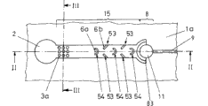
Fig. 1 illustrates the vertical view according to first separation unit bottoms of the present invention,
Fig. 2 illustrates the profile corresponding to the first separator cutting line II-II among Fig. 1,
Fig. 3 illustrates the profile corresponding to the first separator cutting line III-III among Fig. 1,
Fig. 4 illustrates the vertical view according to second separation unit bottoms of the present invention,
Fig. 5 illustrates the profile corresponding to the second separator cutting line V-V among Fig. 4,
Fig. 6 illustrates the profile corresponding to the second separator cutting line VI-VI among Fig. 4,
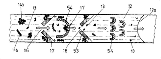
Fig. 7 illustrates according to the part of the 3rd separator of the present invention during separation process,
Fig. 8 is illustrated in the different examples that are used for micro-structured component in first segregation section according to separator of the present invention,
Fig. 9 to 11 is the bottom plan view according to the 4th, the 5th and the 6th embodiment of separator of the present invention,
Figure 12 illustrates a variation according to the entrance structure of separator of the present invention,
Figure 13 illustrates the end vertical view according to the 7th embodiment of separator of the present invention,
Figure 14 illustrates the profile corresponding to the 7th embodiment cutting line XIV-XIV,
Figure 15 illustrates the profile corresponding to the 7th embodiment cutting line XV-XV among Figure 14,
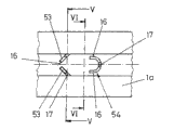
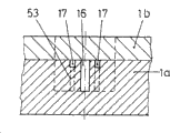
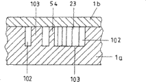
Figure 16 illustrates the sample carrier vertical view of the 8th embodiment,
Figure 17 illustrates the profile corresponding to the 8th embodiment cutting line XVII-XVII among Figure 16,
Figure 18 illustrates one and is used to carry out according to the bottom of the simple mechanism of method of the present invention and the vertical view of sample carrier.
The specific embodiment
The embodiment according to separator of the present invention in the accompanying drawings has the identical and corresponding feature of part of part, and they are represented with identical label symbol.
First embodiment shown in Fig. 1 to 3 has a bottom 1a, forms an inlet 2 with circular cross section therein.Go out first transport path 15 from these 2 lateral branchings that enter the mouth, it extends to the section of compiling 11 always.The described section of compiling 11 is connected with environment by an exhaust passage 9.Capillary plug that is positioned at transfer passage 9 the insides can prevent that the liquid component that accumulates in the section of compiling 11 the insides from discharging.
This capillary plug can be realized by the sudden change physical dimension of transfer passage 9.The surface characteristic of described transfer passage 9 can be suddenlyd change equally, for example from the hydrophily to the hydrophobicity.
The inlet 2 with the section of compiling 11 between transport path 15 be divided into different portion's sections.On the liquid throughput direction, promptly 2 a resuspension section 3, one successively are being set on the direction of the section of compiling 11 are cultivating 4, first segregation sections 5 of section and one second segregation section 8 from entering the mouth.Not only first segregation section 5 but also second segregation section 8 all have micro-structural with micro-structured component 53,54 and the micro-structured component 83 in second segregation section 8 in first segregation section 5.
Except bottom 1a, wherein can be a sample carrier, first separator shown in the part also has a cover plate 1b in Fig. 1 to 3, and its hides transport path 15, the section of compiling 11 and exhaust passage 9 and inlet 2 is exposed.
Be suitable for obtaining blood plasma at first separator shown in Fig. 1 to 3 from blood, wherein haemocyte makes and has only blood plasma to be pooled to the section of compiling 11 in first segregation section 5 and second segregation section, 8 the insides that are retained in transport path 15 when transport path 15 is carried.
Described haemocyte can be by skin effect and the plasma separation that produces when a kind of transport path 15 pumping bloods.
The liquid that contains particulate separates according to following principle at first segregation section 5: the mobility of particulate and compound is compared with all the other liquid and is restricted, and they are carried by capillarity than all the other components of liquid slowlyer.Make the particulate of combination in compound in volume flow, less move again by forming compound (this play improve the quality, the effect of volume and size) than unconjugated particulate.
By join segregation section 5 the insides, preferably continue influence compound in continuous motion or speed in through-flow perpendicular to the micro-structured component 53,54 of flow direction.In compound the particulate of combination with all the other contain particulate sample liquids separate the variation that relates to above-mentioned quality, volume, load and size.
Since the characteristic of its viscoelastic, red blood cell also can slot or capillary through-flow, they are less than its diameter or its thickness.It is complicated and because roll extrusion campaign produces blocks that red blood cell passes the capillary seam that has less than 5 μ m seam hole, and this motion can not be described according to Hagen-Poiseuille.The partition 83 of second segregation section 8 and the seam height of device between the top, when blood plasma will be isolated from blood preferably less than 5 μ m, so that each unconjugated blood cell from sample liquids is blocked in segregation section 8 the insides.Red blood cell blocked or braking at segregation section and can only get into segregation section lentamente, and segregation section 8 does not have or has only small resistance for blood plasma.Depend on that at this erythrocytic hobbing depth seam height and liquid are full of the time of the section of compiling 11 fully.Select the length of segregation section 8 on flow direction like this, that is, made before first red blood cell overcomes segregation section 8 fully, the section of compiling 11 is full of by the blood plasma that moves fully.
Described micro-structured component 53,54 especially in first segregation section 5 with throughput direction on the contrary, promptly form unlimited recessed bag 6a, 6b towards inlet 2 direction.Described micro-structured component 54 is made of the partition of U-shaped on vertical view, and two side leg points to the direction of inlet 2.Between U-shaped side leg, constitute recessed bag 6a.The micro-structured component 53 of first segregation section 5 is made of the partition 53 that favours Way in, and they are connected on the side interface of transport path 15.The acute angle district that constitutes between the side interface of partition 53 and transport path 15 forms the recessed bag 6b of this second micro-structured component 53.Assemble compound and blood particles (haemocyte) in recessed bag 6a, the 6b of micro-structured component 53,54, its conveying along transport path is interrupted thus or is blocked at least, and less blood particles can be passed through first segregation section 5 equally with blocking.But these less particulates are blocked at second segregation section 8, and one of them partition 83 plays the less particle movement effect that stops or block haemocyte at least.Bigger particulate, although their blocked first segregation section 5 that still passes through transport path 15, in any case all stopped by the micro-structured component of second segregation section 8.
Separator according to Fig. 1 to 3 has another feature, and it relates in particular to the second embodiment of the present invention.Described transport path 15 comprised before first segregation section cultivates section 4.In this section the inside or in cultivation section 4 the insides, be added to blood or other in advance and want the material in the processed liquid can act on liquid according to another embodiment of separator of the present invention.Select these materials like this, they are produced or quicken at least to form the compound of forming by the particulate that is included in the liquid, for example form the compound of forming by red blood cell.Especially can produce this compound for blood by cell or the virus that gathering, aggegation or condense red blood cell and/or white blood cell or other are included in the blood.
Cause or impel the material that forms compound to be contained in the resuspension section 3 of first separator.Liquid was flowing through cultivation section 4 on the throughput direction during, material acted on liquid, therefore when liquid arrives first segregation section 5, constituted or constitute basically compound.The compound of particulate or haemocyte is by partly barred and partly slowing down of micro-structured component 53,54.The compound of barred for example accumulates in recessed bag 6a, the 6b the inside of micro-structured component.The particulate that the cumulative volume of all recessed bags preferably equals to be included in the liquid is the volume of haemocyte.Basically only also contain the discrete particle that do not combine or the liquid of haemocyte and arrive first segregation section, 5 ends with compound.Particulate that these are last or haemocyte stop by the partition 83 that is arranged on the there in second segregation section, 8 the insides or block, thereby, when the section of compiling is full of fully, there is not the final section of compiling that arrives of blood plasma of cellular component or similar substance.
The material 3a that is arranged on resuspension section 3 the insides can be placed on the following interface of transport path 15 or resuspension section 3 with tablet form.
At Fig. 4, the partition 53 that the profile of first segregation section of second separator shown in 5 and 6 illustrates a U-shaped partition 54 and favours the throughput direction setting is as micro-structured component, and they are with similar according to the micro-structured component in first segregation section 5 of first embodiment of the separator shown in Fig. 1 to 3.First through flow hole 16 is between two mutual opposed partitions, between the side interface of partition 54 and transport path 15 and between two adjacent partitions 53,53 or 54,54 or 53,54.Be that according to the partition 53,54 of Fig. 4 to 6 and according to the difference of the corresponding partition 53,54 of Fig. 1 to 3 described partition is furnished with second through flow hole 17 at recessed bag 6a, 6b place.The physical dimension of second through flow hole 17 only allows to be included in passing than small particle and/or blood plasma at least individually in the blood, and stops particle complex.Second through flow hole 17 is less than first through flow hole 16.First through flow hole 16 not only allows particle complex but also allows discrete particle and blood plasma to pass through.By second through flow hole 17, air escapes into the section of compiling 11 directions from recessed bag, and liquid and particulate or particle complex enter recessed bag.
Shown in Figure 7, how can be in the 3rd separator by means of from blood, obtaining blood plasma according to method of the present invention.The part of particulate transport path 15 shown in Figure 7, i.e. cultivation section 4 and first segregation section 5.Blood plasma 12 with liquid front 12a is shown in addition, wherein floating individual cells 13, cell mass 14a or so-called haemocyte bunch (Roulaus) 14b in blood plasma.Cell mass 14a and cell cluster 14b are being transported in cultivating section under the influence of the material in the unshowned resuspension section and are forming.Make blood be transported to first segregation section 5 by the capillary force that works along transport path from cultivating section 4.Accumulate in the recessed bag 6a and the 6b the inside of micro-structured component 53 and 54 in this cell mass 14a, cell cluster 14b or individual cells 13.By second through flow hole 17 blood plasma 12 that flows to recessed bag 6a, 6b is equally come out again in recessed bag at throughput direction.Between two adjacent microstructures elements 53 and 54 and first through flow hole 16 between micro-structured component 54 and transport path 15 side interfaces not only allow by individual cells 13 but also allow by compound, as cell mass 14a or cell cluster 14b.Constitute a zone by stopping the compound or the individual cells that are made of cell aggregation fully or substantially in the front end flow surface of blood, this zone is only contained blood plasma and individual cells basically.The mixture that is made of blood plasma 12 and individual cells 13 is transported to second segregation section 8 that is not shown specifically by carrying capacity by first segregation section 5.
Micro-structured component shown in Figure 8 variation in first segregation section can be arranged on first segregation section the inside separately or with different combinations.For micro-structured component a, can be to have the partition or the column of oval cross section basically, they extend to the top part of a separator always from the following interface of first segregation section 5.Described micro-structured component b is a column, and they successively are arranged in three rows.First through flow hole 16 is between two adjacent micro-structured components or between two adjacent micro-structured component b.Described micro-structured component c is the partition of horseshoe-shaped structure, and they pass through adjacent shape of a hoof partition respectively or pass through side interface definition first through flow hole 16 of first segregation section 5.Described partition can extend to the top part 1b of a separator from following interface always, perhaps keeps a slit between the end face of shape of a hoof partition and top part 1b.This slit also is suitable for for micro-structured component a and b and micro-structured component d, wherein relates to the partition of a bending, and they and throughput direction are on the contrary in the extension of first segregation section the inside.First through flow hole 16 is between the end of the partition of two adjacent bendings.
For micro-structured component e, can be a partition, it extends to the interface, second side from the interface, first side on the whole width of transport path 15.In this partition, comprise second through flow hole 17.Changing structure micro-structured component f for one of micro-structured component e, wherein can be an independent shape of a hoof partition, and it is the same with partition e to comprise second through flow hole 17 and extend to the interface, second side from the interface, first side of transport path always.Micro-structured component g also is a partition, and they are with an acute angle setting with throughput direction so that stop and/or the slow down compound and the discrete particle that slows down, but can make liquid component as far as possible interference-free pass through.
According to Fig. 9 according to the 4th embodiment of separator of the present invention except enter the mouth 2 and the section of compiling 11 also have a transport path 15, it has sections 4, one first segregation sections of a cultivation 5, second segregation section 8 and the son field 19 between first segregation section 5 and second segregation section 8.Described transport path 15 with the right angle bending, and connects one second transport path 18 from son field 19 on son field 19, it with cultivate section 4 and first segregation section 5 and be positioned on the straight line.Outwards draw an exhaust passage 9 from this second transport path 18.
Different with above-mentioned example, during whole separation process, a volume flow is arranged from branch point towards second transport path 18 with towards second segregation section 8.Liquid to be filtered flows to second segregation section 8 abreast.Part liquid is correspondingly emitted perpendicular to the direction of the section of compiling 11.Make particulate wash second transport path 18 continuously and the coating on second segregation section, 8 surfaces is reduced owing to want separated liquid to flow to son field 19 continuously by volume flow.Coverage rate can correspondingly change according to volume flow.But volume flow is always with less than 100 Reynolds number laminar flow.Only by capillarity among power-actuated embodiment, volume flow can correspondingly be adjusted by channel size and surface characteristic at liquid.
Shown in Figure 10 according to the fifth embodiment of the present invention, it is with very approximate according to the 4th embodiment of Fig. 9.But be that with the different of the 4th embodiment described son field 19 is arranged on the first segregation section front according to Fig. 9 according to the 5th embodiment of Figure 10.Not only first segregation section 5 but also second segregation section 8 all are parallel to son field 19 and are parallel to from the liquid throughput direction ground of son field 19 to second transport paths 18 and is provided with.Described second transport path 18 is arranged on the straight line extension of cultivating section 4.The layout that is parallel to son field 19 by second segregation section 5 automatically is rinsed the inlet region of first segregation section 5.The inlet region of first segregation section 5 does not stop up by " filter cake " that constitutes there.Realize a constant volume flow at first transport path 15 and second transport path, 18 the insides, be full of end up to the section of compiling 11.
The embodiment according to the 6th embodiment of separator of the present invention and Fig. 1 according to Figure 11 is approximate, wherein with Fig. 1 in the different of first embodiment be, in transport path 15, do not have resuspension section 3.As the micro-structured component of second segregation section 8 are a partition with the slit of erectting perpendicular to following interface (for example the same with micro-structured component e or f among Fig. 8).Liquid component at these second segregation section, 8 back liquid collects in the section of compiling 11 the insides.From the section of compiling 11, there is an exhaust passage 9 to pass the following interface of the section of compiling 11.
Drawing in side sectional elevation shown in Figure 12 according to separator of the present invention.2 the insides described resuspension section 3a is positioned at as circular surface on the following interface of inlet 2 at inlet.The liquid that charges in 2 at inlet directly runs into the material of resuspension section 3a, makes material and the reaction chemistry between the particulate or biological in the liquid be initiated or quicken by it, so that produced the compound with identical or different particulate by particulate.
Have 2, transport paths 15 of inlet and the section of compiling equally at the 7th embodiment according to separator of the present invention shown in Figure 13,14 and 15, wherein second segregation section and the section of compiling are not shown.The inlet and first segregation section 5 only are shown in Figure 13, and this first segregation section 5 has a partition that takes the shape of the letter U in vertical view, and it extends to the top part 1b of separator always from the following interface of first segregation section 5.This partition is separated from each other into two in the hydraulically operated zone that is in front and back on through-flow direction with separator.First area A is arranged between the side leg of partition and directly 2 is connected with entering the mouth.Second area B constitutes by a collection channel, and it is enclosed in the partition that takes the shape of the letter U in the vertical view outside and passes through a transfer passage 22 and is connected with unshowned second segregation section.At the first area micro-structured component of first segregation section 5 for example is to favour partition 53, U-shaped partition 54 or the column 55 that throughput direction is provided with, and they stop with method or the conveying of the compound that slows down and the conveying of discrete particle is slowed down in the above described manner.The above U-shaped partition has a through flow hole 21 in its circular arc in the end of the first area A that is positioned at through-flow direction.The circular arc of described U-shaped partition and side leg are to crack with the even distance at the following interface of the first segregation section 5 top part 1b towards separator.At this width that designs slit 23 like this, that is, the liquid component of discrete particle and liquid can be flow through.Two through flow holes that this slit 23 constitutes on the meaning of the present invention.
Carrying out work according to separator of the present invention is following shown in Figure 13 to 15.Liquid is given to inlet 2, and liquid is transported to the end by capillary force since the first area A of first segregation section 5 therefrom.Stopped by micro-structured component 53,54,55 or slow down at these various compounds and/or particulate at first area A.Liquid component and various compound enter the slit 23 of U-shaped partition.Because the 23 second area B that carry out the transition to segregation section 5 are that a capillary is stopped up for liquid component from the slit, so liquid at first is not transported to second area B by slit 23.The through flow hole 21 that is positioned at circular arc is not designed to capillary and stops up, and the liquid that enters this through flow hole 21 can enter second area B non-resistance.This point for example can realize by breach or similar structures.In case liquid component is full of first area A fully and through flow hole 21 is soaked at U-shaped partition circular arc, liquid just enters second area B and is full of it by through flow hole 21.At this, the outside of liquid-soaked U-shaped partition and slit 23 are offset thus in the capillary of U-shaped partition outside and are stopped up.The liquid that occurs in slit 23 can be from the slit 23 be discharged, liquid and be included in wherein each kind of particulate and begin conveying from the first area A of first segregation section 5 to second area B.At second area B, the liquid component with liquid of various particulates is assembled.Because at the capillary force of second area B and 22 li effects of transfer passage the mixture that liquid component and various particulate are formed is transported to second segregation section, wherein various particulates are by top mode of repeatedly having described and method disengaging liquid.
A kind of for selectable version according to the separator of Figure 13 to 15 in, described U-shaped partition constitutes like this by its micro-structured component (slit), promptly, make this U-shaped partition constitute second segregation section, and described second area is used as the section of compiling according to separator of the present invention in the outside of U-shaped partition according to separator of the present invention.
The device shown in Figure 16 and 17 with constitute approx at the device shown in Figure 13 to 15.First segregation section is surrounded by a partition 103 fully and also also comprises this partition 103.This partition 103 is disconnected by many slits 12, and they make first segregation section be connected with the path 10 2 of the formation section of compiling that is parallel to the first segregation section setting.At this, described slit 23 preferably has the degree of depth identical with collection channel 102.This slit has one and is used for the liquid capillary of 102 directions obstruction from first segregation section to collection channel on throughput direction.Described slit 23 has the degree of depth and the width of 1mm to 500 μ m and the length of at least 50 μ m of 1 μ m to 100 μ m.Described through flow hole 21 has the degree of depth identical with collection channel 102 and does not set up capillary for the liquid that reaches and stop up.
The liquid that will contain particulate be given to pour the zone after, by capillary force segregation section is full of fully.Particulate and compound are partly stopped by micro-structured component 53 and 54 at this.In case liquid is full of through flow hole 21, liquid just flows to collection channel 102 and be full of this passage on Way in (seeing arrow 104).The cross section of collection channel 102 makes the liquid that enters by through flow hole 21 preferably at first be full of pooling zone 102 thus and just continues to flow by collection channel 100 then less than the cross section of collection channel 100.Each slit 23 is soaked into during pooling zone 102 is full of process, offsets its capillary thus and stops up function, makes the at first in fact static liquid of partition 103 inside to flow on collection channel 100 directions by each slit 23.At this; partly barred of slit 23 is also passed through in micro-structured component 54 the insides that particulate or compound are blocked being positioned on the through-flow direction now; thereby, a kind of solution of essentially no particulate is flowed on collection channel 100 directions of leading to the second segregation section (not shown) by pooling zone 102.
Sample carrier shown in Figure 18, also the same at the device shown in the above-mentioned accompanying drawing with all the other, it is applicable to that execution is according to above-mentioned method of the present invention.This sample carrier only has first segregation section 5 and the section of compiling 11 that comprises micro-structured component 2 for this reason except entering the mouth.
Claims (48)
1. the separator of the micro-structural of an each several part that is used for separating liquid, described liquid have the compound of the particulate that mutually combines of the particulate of liquid component and at least a type and/or at least a type, have following feature:
-described device comprises a liquid inlet (2), the section of compiling (11) and the transport path (15) from inlet (2) to the section of compiling (11);
The resuspension section (3) that-described transport path (15) sets gradually before and after being included on the throughput direction, a cultivation section (4), first segregation section (5) and one second segregation section (8), described first segregation section is in order to stop at least a portion compound and/or in order to retardance at least a portion motion compound and/or at least a portion particulate, the motion of described second segregation section in order to stop at least a portion compound and/or at least a portion particulate and/or to be used to block particulate;
-the first segregation section (5) and second segregation section (8) all have a kind of micro-structural, and described micro-structural has one or more micro-structured components.
2. separator as claimed in claim 1, it is characterized in that, the micro-structured component of described first segregation section (5) has the recessed bag (6a) that opens wide towards inlet (2) direction, and/or described micro-structured component comprises having recessed bag (6b) the transport path boundary face adjacent with micro-structured component, that open wide towards inlet (2) direction at least in part.
3. separator as claimed in claim 1 is characterized in that, the micro-structured component of described first segregation section (5) comprises column or upright stone tablet post.
4. separator as claimed in claim 3 is characterized in that described column has a rectangle or oval cross section.
5. as each described separator in the claim 2 to 4, it is characterized in that the micro-structured component of described first segregation section comprises at least one partition (53).
6. separator as claimed in claim 5 is characterized in that, described partition (53) is vertical or favour the throughput direction setting.
7. separator as claimed in claim 1 is characterized in that, the micro-structured component of described first and second segregation sections (5,8) limits one or more first through flow holes (16), and described through flow hole has the physical dimension that allows particulate and compound to pass through.
8. separator as claimed in claim 1 is characterized in that, the micro-structured component of described first segregation section (5) limits first and/or second through flow hole (17), and described through flow hole has the physical dimension that the particulate that only allows particulate or certain type passes through.
9. separator as claimed in claim 8 is characterized in that, described second through flow hole (17) partly is located in the recessed bag (6a, 6b) of micro-structured component of first segregation section (5).
10. as each described separator in the claim 7 to 9, it is characterized in that described first through flow hole (16) has width and/or the height of 1 μ m to 500 μ m.
11., it is characterized in that the flow area of first through flow hole (16) reduces as each described separator in the claim 7 to 9 on throughput direction.
12. separator is characterized in that as claimed in claim 8 or 9, described second through flow hole (17) has width and/or 0.1 μ m to the 100 μ m height of 1 μ m to 500 μ m.
13. separator is characterized in that as claimed in claim 8 or 9, the flow area of described second through flow hole (17) reduces on throughput direction.
14. separator as claimed in claim 1 is characterized in that, at least a material that is used to make particle complex and/or is beneficial to the manufacturing particle complex is set in the resuspension section (3) of described transport path (15).
15. separator as claimed in claim 14 is characterized in that, described at least a material sticks at least one boundary face of resuspension section (3) dryly.
16. separator as claimed in claim 14 is characterized in that, wherein at least a material is with pill shape, tablet shape or Powdered being arranged in the resuspension section (3).
17. separator as claimed in claim 14 is characterized in that, wherein at least a material be placed on the carrier or described carrier impregnation in this material, and described carrier is arranged in the resuspension section (3).
18. as each described separator in the claim 14 to 17, it is characterized in that, described particulate is the particulate of biogenic material at least in part, and one of this material or these materials cause, impel or quicken gathering, agglomeration, the aggegation of active particles and/or condense.
19. separator as claimed in claim 18 is characterized in that, one of described material or these materials at least in part chemical combination on the antigen component of cell surface.
20. separator as claimed in claim 17 is characterized in that, described material or carrier are placed in the space of one of them boundary face of resuspension section (3).
21., it is characterized in that the micro-structured component of described second segregation section (8) comprises a ladder as each described separator in the claim 1 to 4.
22., it is characterized in that the micro-structured component of described second segregation section (8) comprises the column of space as each described separator in the claim 1 to 4.
23., it is characterized in that the micro-structured component of described second segregation section (8) comprises one or more partitions (83) as each described separator in the claim 1 to 4.
24. as each described separator in the claim 1 to 4, it is characterized in that, described separator has a son field (19) before or between first segregation section (5) and second segregation section (8) at first segregation section (5), begins to branch out one second transport path (18) by first transport path (15) from this son field.
25. as each described separator in the claim 1 to 4, it is characterized in that, determine the length dimension of transport path (15) like this to the section of compiling (11), that is, and owing to the leafing effect makes the liquid component and the particulate that have only liquid component or selection type arrive the section of compiling (11).
26. as each described separator in the claim 1 to 4, it is characterized in that, determine the length dimension of transport path (15) like this to second segregation section (8), that is, and owing to the leafing effect makes the liquid component and the particulate that have only liquid component or selection type arrive second segregation section (8).
27., it is characterized in that described cultivation section has a kind of length, a kind of cross section, a kind of profile and/or surface characteristic, adjusts the cultivation time by them as each described separator in the claim 1 to 4.
28. a method that is used for the each several part of separating liquid, described liquid have the compound of the particulate that mutually combines of the particulate of liquid component and at least a type and/or at least a type, this method comprises the following steps:
-at the latest after the cultivation time, in this cultivation time, formed at least a compound, liquid is given on first segregation section (5) of a separator;
-in first segregation section (5), stop the motion of compound and/or the particulate retardance compound and/or certain type by micro-structured component;
-then in the section of compiling (11) of described separator, compile the liquid component separated and particulate part and/or compound.
29. method as claimed in claim 28 is characterized in that, stops compound and/or particulate in second segregation section (8) of described separator, and/or blocks the motion of the particulate of certain type.
30., it is characterized in that begin to add at least a material in the liquid to go in the cultivation time, it plays the effect of making and/or promoting to make the compound of the particulate that mutually combines as claim 28 or 29 described methods.
31. method as claimed in claim 30 is characterized in that, described material, carrier or particulate are that diameter is polymer globules or the glass pellet of 0.05 μ m to 200 μ m.
32. method as claimed in claim 31 is characterized in that, described carrier is by one or more material coating.
33. as claim 28 or 29 described methods, it is characterized in that, place a cultivation section (4) of separator to cultivate liquid.
34. method as claimed in claim 33 is characterized in that, described at least a material is resuspension in a resuspension section (3) of separator.
35., it is characterized in that described compound is at least in part by agglomeration, the aggegation of particulate and/or the formation of condensing as claim 28 or 29 described methods.
36., it is characterized in that described material comprises antibody coating component as claim 28 or 29 described methods, and described compound is made of by the chemical combination of antigen component on film the biological cell that particulate comprised at least in part.
37. as claim 28 or 29 described methods, it is characterized in that, the micro-structured component that moves through in first segregation section (5) of described compound and/or particulate is blocked at least in part, and described compound is stopped by its micro-structured component at least in part.
38. as claim 28 or 29 described methods, it is characterized in that, described compound is stopped by the micro-structured component of second separator and/or particulate is partly stopped by these micro-structured components and/or at least particulate part to move through these micro-structured components blocked.
39., it is characterized in that liquid component of separating and particulate part and/or compound are analyzed in the section of compiling as claim 28 or 29 described methods.
40., it is characterized in that the particulate and/or the compound that concentrate at first segregation section (5) or in second segregation section (8) are analyzed as claim 28 or 29 described methods.
41., it is characterized in that described particulate and/or compound are analyzed in transport path (15,18) as claim 28 or 29 described methods.
42. method as claimed in claim 39 is characterized in that, described analysis comprises a detection optics and/or electrochemical.
43. method as claimed in claim 40 is characterized in that, described analysis comprises a detection optics and/or electrochemical.
44. method as claimed in claim 41 is characterized in that, described analysis comprises a detection optics and/or electrochemical.
45. as claim 28 or 29 described methods, it is characterized in that, in one second section of compiling, concentrate with first section of compiling (11) in dissimilar particulates.
46., it is characterized in that the described section of compiling comprises reaction medium as claim 28 or 29 described methods.
47. method as claimed in claim 45 is characterized in that, the described section of compiling comprises reaction medium.
48., it is characterized in that described liquid is carried by capillary force or the suitable active force of the order of magnitude as claim 28 or 29 described methods.
Applications Claiming Priority (2)
| Application Number | Priority Date | Filing Date | Title |
|---|---|---|---|
| DE10352535A DE10352535A1 (en) | 2003-11-07 | 2003-11-07 | A microstructured separator and method of separating liquid components from a liquid containing particles |
| DE10352535.1 | 2003-11-07 |
Publications (2)
| Publication Number | Publication Date |
|---|---|
| CN1628907A CN1628907A (en) | 2005-06-22 |
| CN100453182C true CN100453182C (en) | 2009-01-21 |
Family
ID=34428663
Family Applications (1)
| Application Number | Title | Priority Date | Filing Date |
|---|---|---|---|
| CNB2004100923056A Expired - Fee Related CN100453182C (en) | 2003-11-07 | 2004-11-08 | Microstructured separation device, and method for separating liquid components from a liquid containing particles |
Country Status (5)
| Country | Link |
|---|---|
| US (1) | US20050106756A1 (en) |
| EP (1) | EP1531003B1 (en) |
| JP (1) | JP2005140790A (en) |
| CN (1) | CN100453182C (en) |
| DE (1) | DE10352535A1 (en) |
Families Citing this family (41)
| Publication number | Priority date | Publication date | Assignee | Title |
|---|---|---|---|---|
| GB0329220D0 (en) * | 2003-12-17 | 2004-01-21 | Inverness Medical Switzerland | System |
| CA2620690A1 (en) * | 2005-08-31 | 2007-03-08 | Nissan Chemical Industries, Ltd. | Microchip for cell response evaluation |
| GB2430393A (en) * | 2005-09-23 | 2007-03-28 | Univ Aston | Micro Device for Automatic Spermatozoa Selection and Cell Sorting |
| CN101305279A (en) * | 2005-11-09 | 2008-11-12 | 皇家飞利浦电子股份有限公司 | Device for testing a fluid |
| EP2017000B1 (en) * | 2007-07-11 | 2012-09-05 | Corning Incorporated | Process intensified microfluidic devices |
| US8591830B2 (en) | 2007-08-24 | 2013-11-26 | Advanced Liquid Logic, Inc. | Bead manipulations on a droplet actuator |
| TW200920841A (en) * | 2007-09-25 | 2009-05-16 | Cytyc Corp | Microfluidic apparatus for manipulating imaging and analyzing cells of a cytological specimen |
| JP5231782B2 (en) * | 2007-10-26 | 2013-07-10 | 学校法人常翔学園 | Device having solid-liquid separation function and method for manufacturing the same |
| CA2716411C (en) | 2008-02-27 | 2015-11-24 | Boehringer Ingelheim Microparts Gmbh | Apparatus for the separation of plasma |
| EP2172260A1 (en) | 2008-09-29 | 2010-04-07 | Corning Incorporated | Multiple flow path microfluidic devices |
| EP2350652A2 (en) * | 2008-10-10 | 2011-08-03 | Cnrs-Dae | Cell sorting device |
| SG184592A1 (en) * | 2011-03-18 | 2012-10-30 | Univ Singapore | Isolating target cells from a biological fluid |
| WO2011078115A1 (en) * | 2009-12-25 | 2011-06-30 | 学校法人常翔学園 | DEVICE HAVING SOLID-LIQUID SEPARATION FUNCTION, μ-TAS DEVICE, AND SOLID-LIQUID SEPARATION METHOD |
| AU2011223512B2 (en) * | 2010-03-05 | 2016-07-21 | Garrett Thermal Systems Limited | Filter bypass |
| WO2011129651A2 (en) * | 2010-04-15 | 2011-10-20 | 주식회사 싸이토젠 | Microfluidic device and method for isolating target using same |
| ITTO20100068U1 (en) * | 2010-04-20 | 2011-10-21 | Eltek Spa | MICROFLUID AND / OR EQUIPMENT DEVICES FOR MICROFLUID DEVICES |
| WO2012024194A2 (en) * | 2010-08-15 | 2012-02-23 | Gpb Scientific, Llc | Microfluidic cell separation in the assay of blood |
| KR101768123B1 (en) * | 2010-12-03 | 2017-08-16 | 삼성전자주식회사 | Hydrodynamic filter, filtering apparatus including the same and filtering method by the same |
| WO2012162779A1 (en) | 2011-05-27 | 2012-12-06 | The University Of British Columbia | Microfluidic cell trap and assay apparatus for high-throughput analysis |
| KR101911435B1 (en) | 2011-09-26 | 2018-10-25 | 삼성전자주식회사 | Apparatus for controlling fluid, filter and bio-chip including the same |
| KR101890743B1 (en) * | 2011-10-05 | 2018-08-23 | 삼성전자주식회사 | Apparatus for controlling fluid and method for controlling fluid by using the same |
| DE102011122579A1 (en) * | 2011-12-29 | 2013-07-04 | Fraunhofer-Gesellschaft zur Förderung der angewandten Forschung e.V. | Process for separating suspension or colloid components and apparatus for separating suspension or colloid components |
| KR101517091B1 (en) | 2012-05-10 | 2015-05-04 | 단국대학교 산학협력단 | Apparatus for separating particle and method for separating and collecting particle |
| US9535082B2 (en) | 2013-03-13 | 2017-01-03 | Abbott Laboratories | Methods and apparatus to agitate a liquid |
| USD978375S1 (en) | 2013-03-13 | 2023-02-14 | Abbott Laboratories | Reagent container |
| US10058866B2 (en) | 2013-03-13 | 2018-08-28 | Abbott Laboratories | Methods and apparatus to mitigate bubble formation in a liquid |
| USD962471S1 (en) | 2013-03-13 | 2022-08-30 | Abbott Laboratories | Reagent container |
| EP3067412A4 (en) * | 2013-11-06 | 2017-07-26 | Japan Science and Technology Agency | Substrate for controlling movement direction of animal cells, and cell identification method and cell separation method which use said substrate |
| EP3226003A4 (en) * | 2014-11-28 | 2018-06-20 | Toyo Seikan Group Holdings, Ltd. | Micro liquid transfer structure and analysis device |
| KR102360072B1 (en) * | 2014-12-08 | 2022-02-08 | 삼성전자주식회사 | Apparatus for classifying micro-particles |
| KR101850852B1 (en) | 2016-01-08 | 2018-04-23 | 재단법인차세대융합기술연구원 | Microfluidic channel device and method for using the same |
| KR102593919B1 (en) * | 2016-03-21 | 2023-10-27 | 주식회사 지노바이오 | A cartridge for cell-capturing |
| US10983745B2 (en) | 2016-06-13 | 2021-04-20 | Lg Electronics Inc. | Display device and display system including same |
| CN106311368B (en) * | 2016-07-29 | 2018-06-15 | 大连理工大学 | A kind of lossless release unit of drop for microsyringe |
| GB2577607B (en) * | 2018-09-28 | 2023-05-17 | Guangdong Acxel Micro & Nano Tech Co Ltd | Droplet actuation |
| US11850583B2 (en) * | 2019-06-12 | 2023-12-26 | Siemens Healthcare Diagnostics Inc. | Plasma separation and sample metering device and kits and methods of use related thereto |
| DE102020004660B4 (en) * | 2020-07-31 | 2022-06-15 | Evorion Biotechnologies Gmbh | Device for the sequential positioning of particles |
| EP4224170A1 (en) | 2020-09-29 | 2023-08-09 | NOK Corporation | Leukocyte trapping apparatus |
| WO2023144192A1 (en) * | 2022-01-25 | 2023-08-03 | Evorion Biotechnologies Gmbh | Device for sequential positioning of particles |
| WO2023189095A1 (en) * | 2022-03-28 | 2023-10-05 | 国立大学法人茨城大学 | White blood cell capturing device |
| WO2023248159A1 (en) * | 2022-06-23 | 2023-12-28 | 3M Innovative Properties Company | Methods and devices for removing particles from fluids |
Citations (4)
| Publication number | Priority date | Publication date | Assignee | Title |
|---|---|---|---|---|
| US5837115A (en) * | 1993-06-08 | 1998-11-17 | British Technology Group Usa Inc. | Microlithographic array for macromolecule and cell fractionation |
| US6156270A (en) * | 1992-05-21 | 2000-12-05 | Biosite Diagnostics, Inc. | Diagnostic devices and apparatus for the controlled movement of reagents without membranes |
| US6319719B1 (en) * | 1999-10-28 | 2001-11-20 | Roche Diagnostics Corporation | Capillary hematocrit separation structure and method |
| US20020196435A1 (en) * | 2000-11-22 | 2002-12-26 | Cohen David Samuel | Apparatus and methods for separating agglutinants and disperse particles |
Family Cites Families (18)
| Publication number | Priority date | Publication date | Assignee | Title |
|---|---|---|---|---|
| US3827555A (en) * | 1973-03-05 | 1974-08-06 | Bio Physics Systems Inc | Particle sorter with segregation indicator |
| US4271119A (en) * | 1979-07-23 | 1981-06-02 | Eastman Kodak Company | Capillary transport device having connected transport zones |
| IT1212882B (en) * | 1983-07-29 | 1989-11-30 | Della Valle Francesco | BASIC DERIVATIVES OF CUMARINA |
| US5135719A (en) * | 1986-10-29 | 1992-08-04 | Biotrack, Inc. | Blood separation device comprising a filter and a capillary flow pathway exiting the filter |
| US5726026A (en) * | 1992-05-01 | 1998-03-10 | Trustees Of The University Of Pennsylvania | Mesoscale sample preparation device and systems for determination and processing of analytes |
| US5304487A (en) * | 1992-05-01 | 1994-04-19 | Trustees Of The University Of Pennsylvania | Fluid handling in mesoscale analytical devices |
| US5885527A (en) * | 1992-05-21 | 1999-03-23 | Biosite Diagnostics, Inc. | Diagnostic devices and apparatus for the controlled movement of reagents without membrances |
| US5905028A (en) * | 1994-05-17 | 1999-05-18 | Gamma Biologicals, Inc. | Method and apparatus useful for detecting bloodgroup antigens and antibodies |
| US5938923A (en) * | 1997-04-15 | 1999-08-17 | The Regents Of The University Of California | Microfabricated filter and capsule using a substrate sandwich |
| DE19733108C2 (en) * | 1997-07-31 | 1999-06-02 | Bartels Mikrotechnik Gmbh | Separator in the submum area |
| GB9800263D0 (en) * | 1998-01-08 | 1998-03-04 | Bio Diagnostics Ltd | A device for testing liquids |
| US6762059B2 (en) * | 1999-08-13 | 2004-07-13 | U.S. Genomics, Inc. | Methods and apparatuses for characterization of single polymers |
| US6451264B1 (en) * | 2000-01-28 | 2002-09-17 | Roche Diagnostics Corporation | Fluid flow control in curved capillary channels |
| US6919046B2 (en) * | 2001-06-07 | 2005-07-19 | Nanostream, Inc. | Microfluidic analytical devices and methods |
| US7456025B2 (en) * | 2001-08-28 | 2008-11-25 | Porex Corporation | Sintered polymer membrane for analyte detection device |
| US7459127B2 (en) * | 2002-02-26 | 2008-12-02 | Siemens Healthcare Diagnostics Inc. | Method and apparatus for precise transfer and manipulation of fluids by centrifugal and/or capillary forces |
| US7312085B2 (en) * | 2002-04-01 | 2007-12-25 | Fluidigm Corporation | Microfluidic particle-analysis systems |
| US20040166551A1 (en) * | 2003-02-24 | 2004-08-26 | John Moulds | Detection of agglutination of assays |
-
2003
- 2003-11-07 DE DE10352535A patent/DE10352535A1/en not_active Withdrawn
-
2004
- 2004-11-02 EP EP04025985.5A patent/EP1531003B1/en not_active Not-in-force
- 2004-11-08 US US10/983,096 patent/US20050106756A1/en not_active Abandoned
- 2004-11-08 CN CNB2004100923056A patent/CN100453182C/en not_active Expired - Fee Related
- 2004-11-08 JP JP2004324376A patent/JP2005140790A/en not_active Ceased
Patent Citations (4)
| Publication number | Priority date | Publication date | Assignee | Title |
|---|---|---|---|---|
| US6156270A (en) * | 1992-05-21 | 2000-12-05 | Biosite Diagnostics, Inc. | Diagnostic devices and apparatus for the controlled movement of reagents without membranes |
| US5837115A (en) * | 1993-06-08 | 1998-11-17 | British Technology Group Usa Inc. | Microlithographic array for macromolecule and cell fractionation |
| US6319719B1 (en) * | 1999-10-28 | 2001-11-20 | Roche Diagnostics Corporation | Capillary hematocrit separation structure and method |
| US20020196435A1 (en) * | 2000-11-22 | 2002-12-26 | Cohen David Samuel | Apparatus and methods for separating agglutinants and disperse particles |
Also Published As
| Publication number | Publication date |
|---|---|
| DE10352535A1 (en) | 2005-06-16 |
| JP2005140790A (en) | 2005-06-02 |
| EP1531003A1 (en) | 2005-05-18 |
| CN1628907A (en) | 2005-06-22 |
| EP1531003B1 (en) | 2016-08-17 |
| US20050106756A1 (en) | 2005-05-19 |
Similar Documents
| Publication | Publication Date | Title |
|---|---|---|
| CN100453182C (en) | Microstructured separation device, and method for separating liquid components from a liquid containing particles | |
| US11944971B2 (en) | Sorting particles in a microfluidic device | |
| CN105026932B (en) | Micro-fluidic distributing equipment | |
| EP2040843B1 (en) | Apparatus for continuous particle separation | |
| JP5684224B2 (en) | Systems and methods for particle focusing in microchannels | |
| US20060246575A1 (en) | Microfluidic rare cell detection device | |
| KR20110088746A (en) | Centrifugal micro-fluidic device and method for detecting analytes from liquid specimen | |
| CN107012067A (en) | A kind of high flux pairing captures micro-fluidic chip and its application of unicellular/individual particle | |
| US20210187508A1 (en) | Systems and methods for particulate encapsulation in microdroplets | |
| JP2010531456A (en) | Module for detecting specimen in fluid and chip having the module | |
| Li et al. | On-chip continuous blood cell subtype separation by deterministic lateral displacement | |
| Farahinia et al. | Recent developments in inertial and centrifugal microfluidic systems along with the involved forces for cancer cell separation: A review | |
| US20180149574A1 (en) | Method of processing specimen and specimen processing apparatus | |
| US20040147043A1 (en) | Microfluidic system for the manipulation and concentration of particles suspended in liquid | |
| JP2020199456A (en) | Separation device | |
| Zhang et al. | On-chip sample preparations for point-of-care cellular analysis of blood | |
| Inganäs et al. | Quantitative bio-affinity assays at nanoliter scale, parallel analysis of crude protein mixtures | |
| Weigl et al. | Standard and high-throughput microfluidic disposables based on laminar fluid diffusion interfaces | |
| Kersaudy-Kerhoas | Design, test and biological validation of microfluidic systems for blood plasma separation |
Legal Events
| Date | Code | Title | Description |
|---|---|---|---|
| C06 | Publication | ||
| PB01 | Publication | ||
| C10 | Entry into substantive examination | ||
| SE01 | Entry into force of request for substantive examination | ||
| C14 | Grant of patent or utility model | ||
| GR01 | Patent grant | ||
| C17 | Cessation of patent right | ||
| CF01 | Termination of patent right due to non-payment of annual fee |
Granted publication date: 20090121 Termination date: 20091208 |