CN100457214C - Double-headed insufflator and its volute - Google Patents

Double-headed insufflator and its volute Download PDF

Info

Publication number
CN100457214C
CN100457214C CNB021542899A CN02154289A CN100457214C CN 100457214 C CN100457214 C CN 100457214C CN B021542899 A CNB021542899 A CN B021542899A CN 02154289 A CN02154289 A CN 02154289A CN 100457214 C CN100457214 C CN 100457214C
Authority
CN
China
Prior art keywords
air feeder
turbine
air
electromotor
positive airway
Prior art date
Legal status (The legal status is an assumption and is not a legal conclusion. Google has not performed a legal analysis and makes no representation as to the accuracy of the status listed.)
Expired - Fee Related
Application number
CNB021542899A
Other languages
Chinese (zh)
Other versions
CN1432415A (en
Inventor
杰弗里·戴利
亚历山大·维尔
斯蒂芬·A·利
戴恩·C·C·马丁
尼克·里德
拉里·帕克里奇
傅俊晖
Current Assignee (The listed assignees may be inaccurate. Google has not performed a legal analysis and makes no representation or warranty as to the accuracy of the list.)
Reisman Private Limited
Original Assignee
Resmed Pty Ltd
Priority date (The priority date is an assumption and is not a legal conclusion. Google has not performed a legal analysis and makes no representation as to the accuracy of the date listed.)
Filing date
Publication date
Family has litigation
First worldwide family litigation filed litigation Critical https://patents.darts-ip.com/?family=23319402&utm_source=google_patent&utm_medium=platform_link&utm_campaign=public_patent_search&patent=CN100457214(C) "Global patent litigation dataset” by Darts-ip is licensed under a Creative Commons Attribution 4.0 International License.
Application filed by Resmed Pty Ltd filed Critical Resmed Pty Ltd
Publication of CN1432415A publication Critical patent/CN1432415A/en
Application granted granted Critical
Publication of CN100457214C publication Critical patent/CN100457214C/en
Anticipated expiration legal-status Critical
Expired - Fee Related legal-status Critical Current

Links

Images

Classifications

    • AHUMAN NECESSITIES
    • A61MEDICAL OR VETERINARY SCIENCE; HYGIENE
    • A61MDEVICES FOR INTRODUCING MEDIA INTO, OR ONTO, THE BODY; DEVICES FOR TRANSDUCING BODY MEDIA OR FOR TAKING MEDIA FROM THE BODY; DEVICES FOR PRODUCING OR ENDING SLEEP OR STUPOR
    • A61M16/00Devices for influencing the respiratory system of patients by gas treatment, e.g. mouth-to-mouth respiration; Tracheal tubes
    • A61M16/0057Pumps therefor
    • A61M16/0066Blowers or centrifugal pumps
    • A61M16/0069Blowers or centrifugal pumps the speed thereof being controlled by respiratory parameters, e.g. by inhalation
    • FMECHANICAL ENGINEERING; LIGHTING; HEATING; WEAPONS; BLASTING
    • F04POSITIVE - DISPLACEMENT MACHINES FOR LIQUIDS; PUMPS FOR LIQUIDS OR ELASTIC FLUIDS
    • F04DNON-POSITIVE-DISPLACEMENT PUMPS
    • F04D17/00Radial-flow pumps, e.g. centrifugal pumps; Helico-centrifugal pumps
    • F04D17/08Centrifugal pumps
    • F04D17/16Centrifugal pumps for displacing without appreciable compression
    • F04D17/164Multi-stage fans, e.g. for vacuum cleaners
    • FMECHANICAL ENGINEERING; LIGHTING; HEATING; WEAPONS; BLASTING
    • F04POSITIVE - DISPLACEMENT MACHINES FOR LIQUIDS; PUMPS FOR LIQUIDS OR ELASTIC FLUIDS
    • F04DNON-POSITIVE-DISPLACEMENT PUMPS
    • F04D25/00Pumping installations or systems
    • F04D25/02Units comprising pumps and their driving means
    • F04D25/08Units comprising pumps and their driving means the working fluid being air, e.g. for ventilation
    • F04D25/084Units comprising pumps and their driving means the working fluid being air, e.g. for ventilation hand fans
    • FMECHANICAL ENGINEERING; LIGHTING; HEATING; WEAPONS; BLASTING
    • F04POSITIVE - DISPLACEMENT MACHINES FOR LIQUIDS; PUMPS FOR LIQUIDS OR ELASTIC FLUIDS
    • F04DNON-POSITIVE-DISPLACEMENT PUMPS
    • F04D25/00Pumping installations or systems
    • F04D25/16Combinations of two or more pumps ; Producing two or more separate gas flows
    • F04D25/166Combinations of two or more pumps ; Producing two or more separate gas flows using fans
    • AHUMAN NECESSITIES
    • A61MEDICAL OR VETERINARY SCIENCE; HYGIENE
    • A61MDEVICES FOR INTRODUCING MEDIA INTO, OR ONTO, THE BODY; DEVICES FOR TRANSDUCING BODY MEDIA OR FOR TAKING MEDIA FROM THE BODY; DEVICES FOR PRODUCING OR ENDING SLEEP OR STUPOR
    • A61M2205/00General characteristics of the apparatus
    • A61M2205/42Reducing noise

Abstract

The present invention disclosed a double-ended variable speed blower for Continuous Positive Airway Pressure (CPAP) ventilation of patients which includes two impellers in the gas flow path that cooperatively pressurize gas to desired pressure and flow characteristics. Thus, the double-ended blower can provide faster pressure response and desired flow characteristics over a narrower range of motor speeds, resulting in greater reliability and less acoustic noise.

Description

Double end air feeder and spiral case thereof
Technical field
The present invention relates to a kind of device that is used for providing breathable gas to human body, as be used in lasting positive airway pressure (Continuous Positive AjrwayPressure (the CPAP)) therapy of obstructive sleep apnea (OSA) treatment, and be used for some other respiratory disease and disease such as emphysema and assisted ventilation.
Background technology
The CPAP therapy of OSA is a kind of form of no wound positive airway pressure therapy (NIPPA), but it relates to the respiratory tract that the respiratory gas (being air generally speaking) that utilizes pipeline and the pressurization of face shield handle is transported to patient.The gas pressure that is used for CPAP can change in the scope between the 28cm water column at the 4cm water column according to patient's needs situation, and its peak flow rate (PFR) can reach 180L/min (recording) on face shield.For patient's respiratory tract, gas-pressurized can serve as the gas thin plate that is used for preventing airway collapse, particularly during the suction condition in respiratory.
Pressure when in typical case, giving patient ventilating in the CPAP process is that the state according to the patient respiration cycle changes.For example, the device of this ventilation can be to be preset as to carry two kinds of pressure, a kind of is the positive airway pressure of suction (IPAP) in breathing cycle suction condition process, and another kind is exactly the positive airway pressure of exhalation (EPAP) in breathing cycle expiration state procedure.The idealized system of CPAP is to provide for patient under the situation that maximum pressure supports in suction condition early stage, can be between IPAP and EPAP pressure fast, effectively, undisturbedly switch.
In a conventional CPAP system, the gas that offers patient is by an air feeder pressurization with single turbine.This turbine is enclosed in a spiral case or the shell, and the gas that enters therebetween collects by the revolving wormgear pressurization.Gas-pressurized little by little leaves spiral case and is transported in patient's the face shield subsequently.
There are two kinds of general methods to be used for disposing air feeder and turbine at present, enable to produce the needed two kinds of different pressure of desirable CPAP system, IPAP and EPAP.First method is to produce a kind of continuous high pressure by adjusting electromotor/turbine, then by adopting a by-pass valve to modulate high pressure, thereby obtains required IPAP and EPAP pressure.The CPAP system of making according to first method is called the single speed two-bed system of being with diverter.Second method is to drive turbine by acceleration motor, thereby directly produces IPAP and EPAP pressure.The CPAP system of making according to second method is referred to as the speed change two-bed system.
There are a lot of specific shortcomings in speed change twin-stage CPAP system.First shortcoming is in order to switch fast between IPAP and EPAP, and turbine must quicken and slow down apace.Cause turbine, electromotor, bearing upper stress excessive like this.If but slowly quicken turbine, the rising speed of pressure then can not reach requirement so, thereby makes patient can not get sufficient treatment.
Electromotor and turbine quicken and slow down also to cause producing too much heat and undesirable noise fast.(noise of said here " unhappy " refers under the situation of not considering volume, produces the over-drastic sound that causes the frequency of patient's agitation.) in addition, the designer also usually is forced to take compromise proposal, have nothing for it but the surge pressure that obtains wishing and sacrificed best pressure and flow behavior.
Summary of the invention
On the one hand, the present invention relates to and have faster pressure rise time and more high reliability and low noise speed change air feeder.
According to the present invention, a kind of air feeder is provided, comprising: an electromotor; An axle links to each other with electromotor, and described axle comprises and limits a pivot center by the first and second relative axle heads; A first order turbine is fixed on described first axle head, and described first order turbine comprises one first air inlet; And a second level turbine is fixed on described second axle head, and described second level turbine comprises one second air inlet; Wherein said air feeder also comprise a cover with fastening electromotor and limit at least in part one near the gas passage of electromotor so that with gas from first order turbine guiding second level turbine, and second air inlet is around second axle head and along the described axis setting between first order turbine and second level turbine.
Air feeder according to the present invention comprises a gas flow path between air inlet and gas outlet, an electromotor and a cover turbine assembly.
Preferably, turbine assembly can comprise that one links to each other with electromotor and make that it centers on the axle of first axle rotation, for example is fixed on first and second turbines on described with ining addition.Turbine is placed in the air-flow, and links to each other with another one turbine fluid by gas flow path, can be used between air inlet and the gas outlet synergistically the air-flow of air inlet to the gas outlet being pressurizeed thereby make all turbines all be placed on.
In one embodiment, turbine sequentially is placed between air inlet and the gas outlet.Air feeder can also comprise a shell, and this housing parts is positioned at around first and second turbines.Specifically, this shell can hold first and second spiral cases, and first spiral case holds the air-flow around first turbine, and second spiral case holds the air-flow around second turbine.Air inlet can be placed on the interior gas outlet of first spiral case and then can be placed in second spiral case.
Turbine can vertically be placed at each interval along first.Specifically, they can be placed on respectively on two opposite ports of air feeder shell.
Can structurally change to some extent according to air feeder of the present invention.In one embodiment, two turbines are designed to along same direction rotation.In another embodiment, two turbines are designed to rotate in the opposite direction.
Another aspect of the present invention relates to a kind of plane transitional type spiral type spiral case that is used for double end or single head air feeder.This plane transitional type spiral type spiral case can little by little guide gas-pressurized from the turbine of rotation.
Foregoing of the present invention and others will be clear to explanation in the specific descriptions of preferred embodiment below.
Description of drawings
Different example embodiment will be described in conjunction with following accompanying drawing, the wherein identical identical feature of reference marks representative, wherein:
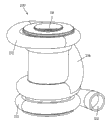
Fig. 1 is the perspective view according to a double end air feeder of first embodiment of the invention.
Fig. 2 is the perspective cutaway view, of the double end air feeder among Fig. 1.
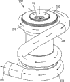
Fig. 3 is the perspective view according to a double end air feeder of second embodiment of the invention.
Fig. 4 is the profile perspective of the double end air feeder among Fig. 3.
Fig. 5 is the back perspective view of the double end air feeder among Fig. 3, has described the flow direction of gas.
Fig. 6 is the perspective view that is applicable to the plane transitional type spiral type spiral case in the air feeder of the present invention.
Fig. 7 is the decomposition diagram of a double end air feeder according to another preferred embodiment.
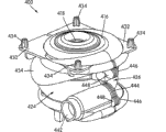
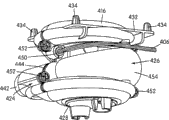
Fig. 8 is the assembling perspective view of the double end air feeder of Fig. 7 of seeing from a side; With
Fig. 9 is the assembling perspective view of the double end air feeder of Fig. 7 of seeing from another side.
The specific embodiment
With reference now to accompanying drawing, describe, Fig. 1 is the perspective view according to a double end air feeder 100 of first embodiment of the invention.Air feeder 100 is generally cylindrical, and its two ends have turbine shell or spiral case 112 and 113.Air feeder can hold two turbines 114 and 115, this point can be in the profile perspective of Fig. 2 best image.
Referring to Fig. 1 and Fig. 2, two turbines 114 and 115 are placed with and make it gas circuit by gas passage 116 and link to each other.The gas passage 116 of air feeder 100 comprises the pipe that extends to second spiral case 113 from first spiral case 112, the terminal of gas passage 116 is a circular profile, and merge with main body gradually, form an independent overall structure near the air feeder 100 of spiral case 112 and 113.Gas passage 116 can be the rigid conduit of the whole molds of other parts of and air feeder 100, and perhaps it can be the pipeline (for example flexible duct of metal or plastics) of a flexibility.
Air feeder 100 has an independent air inlet 118, and its position is that air or other suitable gas can directly flow in first spiral case 112 by this import, and the revolving wormgear 114 that is positioned in first spiral case 112 absorbs.In a single day gas be introduced into air inlet 118 and will ceaselessly circulate, and the motion by turbine 114 obtains pressurization before leaving spiral case 112 gradually and entering into gas passage 116.In case enter within the gas passage 116, air can flow to second spiral case 113, further circulation in spiral case 113, and the motion of the turbine 115 by second spiral case 113 obtains pressurization before leaving air feeder 100 by output channel 120.Air glide path among Fig. 1 in the air feeder 100 is represented by arrow.As shown in the figure, 116 one along the gas passage straight relatively part circulation of the gas in air feeder 100, and enter into (not shown in figure 1) in second spiral case 113 by an adjacent snout cavity on second spiral case 113.
If turbine 114 and 115 is designed to multiple operation rather than continuous operation, air feeder 100 can have two air inlets 118, is respectively applied for spiral case 112 and 113.Need in the CPAP of the high flow rate low-pressure equipment if be placed on, this parallel turbine modes of emplacement is favourable.Yet, also have some other devices can be used in the CPAP equipment of low-pressure in this area and produce high flow rate.
The design of gas passage 116 can have influence on the overall performance of air feeder 100.Generally speaking, there are several design considerations can have influence on according to employed gas passage in the air feeder of the present invention.The first, employed gas passage should farthest provide low flow resistance in the air feeder of the present invention, because the low flow resistance in the gas passage can reduce in the air feeder pressure drop between two spiral cases 112 and 113.The second, the gas passage is arranged so that preferably the gas that enters second spiral case 113 can enter from the designed direction of the blade of turbine 115.(as below inciting somebody to action in greater detail, two turbines of air feeder of the present invention can be designed to equidirectional or different directions rotation.) last, be a kind of Compact Design of the best according to the gas passage of air feeder of the present invention.
The preferred forms that above-mentioned design is considered is to use a long and thick bend pipe to reduce the pressure drop of corner in air flue.It equally also is favourable that a straight relatively part this point is arranged after turning round in the gas passage, because the straight relatively part after turning round can allow air-flow fully to enlarge before entering spiral case.The suitable length of the straight gas passage part after turning round is about three times of gas passage diameter.The air-flow that this straight relatively part has also guaranteed to enter 113 li of second spiral cases is axial, and this is the gas flow of a lot of turbine design just.If wish to obtain other airflow pattern, also can in air feeder, increase stator vane or other similar direct fluid structure, but stator vane be very big expending aspect flow resistance and the pressure drop.
Consider the main design aspect of three above-mentioned gas passages, because straight relatively part is one of shortest path possible between two spiral cases 112 and 113, thereby the gas passage among the embodiment that describes among Fig. 1 116 has a long and straight relatively part.Those of skill in the art can know that it all is straight that gas passage 116 there is no need integral body.
Can hand-designed finish according to air feeder of the present invention, the experimental measurement data of air-flow and pressure are optimized the design of gas passage 116 and other parts in employing prototype and these prototypes.Perhaps, they can carry out global design or partial design by hydrokinetics calculation machine simulation program.Multiple fluid dynamics calculation machine simulation program is arranged in the prior art.The hydrokinetics calculation machine simulation program that is particularly suitable for air feeder design of the present invention comprises FLOWORKS (NIKA GmbH, Sottrum, Germany), ANSYS/FLOTRAN (the Ansys company of Pennsylvania, America Canonsburg) and CFX (the AEA engineering software company of the El Dorado Hills of California, USA).These simulation programs can make the user see the effect of gas passage design variation in mimic air-flow.
With gas passage 116 many different class of establishments can be arranged according to two spiral cases 112,113 in the double end air feeder of the present invention.Generally speaking, each spiral case is designed to make gas to keep a bit of time around turbine, and can allow gas to progress in the gas passage.The accurate structure of this gas passage can depend on multiple factor, comprises the structure and the handedness of spiral case, or the airflow direction around each turbine.
The design of spiral case itself is a technology, because design generation and stream condition that incorrect spiral case can produce noise or influence required pressure.Above-mentioned hydrokinetics calculation machine simulation program also can help to design spiral case, can hinder fully usually and designs spiral case with computer though be included in variable number in the Volute Design process.
Spiral case 112 and one of 113 general problem are that their transition portions of linking to each other with gas passage 116 are too rapid.Rapid transition between spiral case 112,113 and gas passage 116 usually can be stayed next fork-shaped passage or formation " lip shape " at opening part.When this lip shape of turbo blade process, can produce the noise of a kind of being referred to as " blade is through overfrequency ".Spiral case preferred design according to double end air feeder of the present invention becomes can reduce " blade is through overfrequency " or produce other noise.
Fig. 6 is a perspective view that is suitable for use in a plane transitional type spiral type spiral case 300 in the air feeder that designs according to the present invention.In addition, spiral case 300 can be used in any traditional air feeder equipment.As shown in Figure 6, spiral case 300 has the electromotor 302 of self, has independent electromotor with in the double end air feeder that orders about two turbines in the spiral case though it can be useful in one.As shown in the figure, spiral case 300 comprises two and half ones 304 and 306, and this two and half one is respectively the top and the bottom of spiral case 300.The air inlet 308 of spiral case is positioned at the centre of the first half 304.This two and half one 304 and 306 defines a passage, this passage and the air that rotates with turbine slow " peeling off ".In the passage that this two and half one defines, rapid " lip shape " or " slight crack " that do not have conventional turbine and had, thereby make " blade is through overfrequency " can be reduced or complete obiteration.The spiral case of describing among Fig. 6 300 is particularly suitable for short and wide relatively electromotor.
Alternatively, can adopt the spiral case of any common model according to the size that is installed in electromotor in the air feeder.The model that another of spiral case is suitable is a disclosed axial spiral case in the United States Patent (USP) (application number is 09/600738) of application on July 21st, 2000, and the content of this patent here can integral body be introduced among the application as a reference.
One of the double end air feeder of design important design considers it is " handedness " according to the present invention, or the airflow direction around each turbine.This " handedness " can be by the direction decision of turbine rotation, perhaps can be by the orientation and the structures shape of the independent blade of turbine.For example, being oriented to of the rotation of a turbine or the blade on it drives air in a clockwise direction, and being oriented to counterclockwise to drive air of the rotation of another one turbine or the blade on it so just formed the double end air feeder of " opposite rotation direction ".Optionally, these turbines all can be driven on same direction, thereby constitute the double end air feeder of " identical rotation direction ".Air feeder 100 among Fig. 1 is examples of the double end air feeder of opposite rotation direction type.
The advantage of " identical rotation direction " air feeder is that two turbines can be identical, has so just reduced the part number and the expense of air feeder.Yet, should be noted that the designer can select to design the air feeder of an identical rotation direction, wherein mobile two turbines of air that are used in spiral case separately can design respectively and optimize.
The air feeder of " opposite rotation direction " allows the designer to reduce the length of the axle of installation turbine.This can improve the stability of axle self, because it has reduced the problem that is associated with the long cantilever unbalanced shaft of high speed rotating.
Fig. 3 shows the air feeder 200 of according to the present invention one " identical rotation direction " of design.Air feeder 200 equally also has 212,213, one gas passages of two spiral cases 216, an air inlet 218 and a gas outlet 220.Yet as shown in Figure 3, gas passage 216 has spiral-shaped.In other words, come from first spiral case 212 transition in gas passage 216, along with the circumferential of air feeder 200 has a down dip, turn round then and gradually and an inlet chamber between electromotor 150 and arcuate flanges 160 combine together, this inlet chamber has served as gas feed in air feeder 200.The air-flow of air feeder 200 of flowing through is represented with the arrow in Fig. 5 perspective view.
The internal structure of air feeder 200 has been shown in the perspective cutaway view, of Fig. 4. Air feeder 100 and 200 internal structure are closely similar, below just describe in conjunction with the suitable part of two air feeders.As shown in Figure 4, motor 150 is installed in the center of air feeder 200.Various known supports and assembly parts can be used for supporting electromotor, and guarantee that electromotor is in the inside of air feeder 200, but these parts all do not have shown in Figure 4 for simplicity.
Electromotor 150 orders about a single axle 152.This 152 center along air feeder 100,200 passes completely through the whole length of air feeder, and guarantees that turbine 114,115 and 214,215 is positioned at each end.This can be circle, the side, wedge shape or other the shape that can arrive power transfer turbine 114,115 and 214,215.At turbine 114,115,214,215 and axle can connect by the interference fit between two parts, weld seam, adhesive glue or securing member such as screw between 152.In air feeder 100 and 200, axle 152 and turbine 114,115, by at turbine 114,115, the annular lip 154 of 214,215 intermediate vertical orientations (that is to say along the axial orientation of axle 152) formation connects between 214,215.In Fig. 3 and Fig. 4, turbine 114,115,214,215 and axle connect by interference fit between 152.
Turbine 114,115,214,215 is being annular fully in shape.Turbine 114,115,214,215 core 156 be one and extend radially outwardly into the thin dish of blade 158 from axle 152, and when it from axle 152 outwards when blade 158 extends, it is bent downwardly by upwards arching upward to graduate into.The actual diameter of each turbine 114,115,214,215 can be littler than the turbine diameter in the conventional air feeder with single turbine.Boosting fast in air feeder needs the rotatory inertia of a low speed, and this inertia becomes biquadratic to change with diameter.Because the turbine 114 and 214 of air feeder 100 and 200 is smaller on diameter,, thereby can provide the pressure rise time faster so their rotatory inertia is smaller.Except diameter, other design parameters of turbine 114,214 can be adjusted, to obtain a lower rotatory inertia.Another technology that is used for reducing rotatory inertia comprises makes case " fan-shaped ", the turbine of a kind of to produce " starfish appearance ", use the inner rotation electromotor, and adopt and to cast the material of thin-walled portion such as turbo blade that liquid crystal polymer is made hollow and reinforce by rib.
With reference to figure 4 and Fig. 5, there is shown the double end air feeder of identical rotation direction, open at the top of first spiral case 212, thereby form an air inlet 118.At air inlet 118 places, the top surface 120 inside bow actions of air feeder 100 form a lip 122 on the top of turbine 214.The lip 122 of shape that turbine core 156 is bent upwards and top surface 120 is limited in the air that enters in the volume of the air feeder within first spiral case 212, helps also simultaneously to prevent that the gas in the operating process from leaking.Curved flanges 160 that is similar to arch roof surface 120 extends out from the low inner surface of air feeder 200, forms the annular top of second spiral case 213.Odd-shaped chassis 162,262 has formed the bottom of second spiral case 113,213 of air feeder 100 and air feeder 200.There is a hole that can allow gas passage 116 to enter on the chassis 162 of air feeder 100 at the center, the chassis 262 of air feeder 200 does not then have such hole.As mentioned above, curved flanges 160 has been served as the air inlet of second spiral case 213 of air feeder 200.In air feeder 200, stator vane and additional air-flow orthopaedic component can be added on the chamber between electromotor 150 and the curved flanges 160, be used for assisting and distribute the air that enters, air can enter into second spiral case from all sides rather than preferentially flow into from one side thus.
Can find out obviously that from Fig. 2 and Fig. 4 the air feeder of design can have the compromise face of a lot of complexity according to the present invention.Those shaped faces that adopt in arc top surface 120 and curved flanges 160 can be used for steering current and prevent flow leakage.When oxygen content in the air-flow of the air feeder 100,200 of flowing through when higher, prevent to leak just extremely important.If adopt the gas of rich oxygen content, the leakage of gas can cause danger.Even do not consider any safety problem, escape of air also can produce undesirable noise, also can reduce the performance of air feeder simultaneously.
The quantity of the complicated compromise face that exists in the air feeder of design according to the present invention is particularly suitable for as production methods such as investment castings.Though relatively expensive, model casting can produce parts that have a plurality of hidden and recessed features, could realize identical functions and other producer rule will be designed to a plurality of parts.Yet in order to reduce the probability that gas leaks as far as possible, number of components is too much normally unaccommodated, and the number of parts preferably should remain on a minima, and the number that connects between the parts also can preferably remain on a minima.
Also has consideration on a lot of materials for the air feeder of the present invention design.Most typical in the model casting is to adopt metal, but some metal pair oxidation is responsive especially, and this is the problem that needs are concerned about, because medical oxygen is used on the air feeder of the present invention.A kind of material of air feeder 100,200 particularly suitables is an aluminum.But iron and steel is exposed in the high-concentration oxygen and can gets rusty, and aluminum is oxidation rapidly then, and its oxide forms a kind of impervious sealing on metal.No matter use which kind of metal or other material, the high thermal conductivity of material also is very important, and it can be taken heat out of from the gas passage, thereby can avoid because of being heated oxygen being lighted.
Although use aluminum to have many good qualities, it has " ringing " or claims the trend of sympathetic response when air feeder is operated.Therefore can in the aluminum air feeder, damping material be installed, to reduce the intensity of aluminium part vibration.
In air feeder 100 and 200, with different speed drive motors 150, thus IPAP that obtains wishing and EPAP pressure.This double end of air feeder (that is to say two stages) design means that the velocity variations scope of electromotor is reduced in order to obtain this two kinds of pressure.The pressure response time that the less excursion of engine speed causes its pressure response time and provided than the single stage air feeder with same engine power and drive characteristic is shorter.In addition, less variation can make rotary system partly bear smaller stress on the speed, thereby can improve stability and reduce noise.
Air feeder 100 and 200 performance approximately and the binding abilities of two turbines/spiral case associatings deduct two spiral cases 112,113, the value between 212,213 behind the pressure/flow curve of venting channels 116,216 is suitable.Because a variety of causes of knowing in this area, the actual performance of air feeder 100,200 will depend on the moment air velocity and many factors of specific air feeder 100,200.Under high flow condition, 116,216 li pressure drop is normally quite tangible in the gas passage.
Double end air feeder according to the present invention can use with the same mode of conventional air feeder and be placed in the CPAP device.This air feeder is typically and is placed on spring or other shock-damping structure to reduce vibration.Further embodiment
Fig. 7 shows an alternative embodiment of the invention, and this figure is a decomposition diagram according to double end air feeder 400 of the present invention.In this embodiment, the electromotor and the stator vane part 402 that are positioned at the exploded view center are come out by aluminum model casting, but other process that will describe below also can using.Aluminum can promote the heat that electromotor produced that dissipates and quicken or slow down as a kind of good heat conductor.Each end of axle 404 has been shown among Fig. 7, but electromotor coil, bearing and outer housing do not illustrate in the drawings all.The power line 406 of electromotor stretches out from electromotor and stator vane part 402, and withdraws from air feeder 400 by seal 450.The top bag of electromotor and stator vane 402 has been given up the bottom of upper volute 408.
As a variation of design shown in Figure 7, electromotor and stator vane part 402 can be made separately from the bottom of upper volute 408.If these two parts are to do separately, just do not needed model casting.For example, engine main body can be the mold pressing foundry goods, and the bottom of upper volute 408 then can be an injection molding.
By screw or other securing member a disk 410 is fixed on electromotor and the stator vane part 402, a hole 412 as axle 404 passages is arranged in the middle of the disk.Turbine 414 leans against the disk top.Turbine 414 becomes fan-shaped along its circumference, to reduce its rotatory inertia, makes it look like " Asterias amurensis Lutken " shape.
Upper end cover 416 be fastened on turbine 414 above, the top of upper volute also is provided simultaneously.In this embodiment, spiral case all is a version of plane transitional type spiral type spiral case 300 shown in Figure 6 up and down.Air inlet in upper end cover 416 intermediary holes 418 as air feeder 400.
In the lower end of air feeder 400, a special-shaped dish 420 forms the upper part of spiral case down.Rise at the top of special-shaped dish 420, simultaneously the arc hole 422 of leading to downwards of curve.As mentioned above, special-shaped plate can help air-flow is regulated, and guarantees that air-flow can flow into the turbine chamber from all directions, rather than preferably flows into from a direction.Below abnormal shape dish 420, following turbine 415 is in the place rotation near bottom end cover 428.Two end caps 416,428 can be mold pressing foundry goods (making as aluminum or magnesium alloy), or can be formed by a kind of suitable metal injection.
In the gas passage 454 between the spiral case up and down are integral parts that left side cover 424 and right side cover 426 constitute, and fastening other parts above the cover of right side.Left side cover 424 also provides the gas outlet 442 of air feeder 400.By screw or other securing member that can remove left and right sides cover 424 and 426 is tightened together.On the upper surface of left and right sides cover 424,426 is the square-shaped flange 430,432 with projection 434,436, and these projections can make air feeder 400 can be installed on the spring of CPAP apparatus the inside.Projection 434,436 shown in Fig. 7 can be of different sizes and shape, but the projection 434 in Fig. 8 and Fig. 9 is of similar shape.Be appreciated that characteristic and mounting means, can make projection 434,436 adopt shape or other shape of any description according to the spring that air feeder 400 is installed.
Double end air feeder 400 also comprises two damped sleeves 438,440.Damped sleeve 438,440th, the rubber of injection molding or foam rubber parts can be respectively and the interior outline of left and right sides cover 424,426.In one embodiment, damping sleeve pipe 438,440th, the polyurethane of 40 Shore A hardness that form by the mold pressing of a rapid prototyping silicones.As selection, damping sleeve pipe 438,440 can be silicones or some other stable elastomer of energy under the high temperature that electromotor produces.
Damped sleeve 438,440 has three main effects in air feeder 400: form actual air duct 454, provide sealed environment between other parts, reduce the vibration of other parts.The damped sleeve 438,440 of rubber or foam rubber material is suitable especially for gas passage 454, because it allows die (promptly recessed).The damping characteristic of damped sleeve 438,440 has reduced ringing that aluminium parts more or less can exist.
Fig. 8 is the assembling perspective view of air feeder 400 1 sides.There is shown the gas outlet 442 of assembling and the seam 444 between the left and right sides cover 424,426.Shown in the perspective view that rotates among Fig. 8 and Fig. 9, flange 446,448 is laterally projecting from the edge of each side cover 424,426, forms seam 444 in abutting connection with ground afterwards.This two side covers 424,426 are together fastening by screw 452, and this screw enters into the screwed hole on the flange 448 of left side cover 424 through the flange 446 of right side cover 426.
Air feeder 400 has several advantages.The first, producing air feeder 400 does not need model casting, like this can reduce the cost of air feeder.In addition, because the parts of air feeder 400 seldom have hiding and complicated part, so foundry goods is checked and cleaning easily.At last, air feeder 400 is than the easier assembling of other embodiment, because can just can clamp parts by two some simple securing members of side cover 424,426 usefulness.
Though by embodiment this invention is described, is understandable that the description here is not that invention is limited.Under the prerequisite that does not depart from the scope of the invention and spirit, can aspect bigger, carry out some changes.Though invention described herein, is understandable that the present invention is not limited to disclosed details with reference to specific embodiment.The present invention can extend to all similar structure, purposes and machinerys of being suitable for.

Claims (27)

1. an air feeder (100,200,400) comprising:
An electromotor (150,402);
An axle (152,404) and electromotor (150,402) link to each other, and described axle comprises and limits a pivot center by the first and second relative axle heads;
A first order turbine (114,214,414) is fixed on described first axle head, and described first order turbine comprises one first air inlet (118,418); And
A second level turbine (115,214,414) is fixed on described second axle head, and described second level turbine comprises one second air inlet (422);
Wherein said air feeder also comprises a cover (424,426) with fastening electromotor (402) with limit a gas passage (116 near electromotor at least in part, 216,454) so as with gas from first order turbine (114,214,414) guiding second level turbine (115,215,415), and second air inlet around second axle head and along described axis setting between first order turbine and second level turbine.
2. air feeder as claimed in claim 1, wherein said cover comprise first half-sum fixed to one another the second half (424,426).
3. as the air feeder of claim 1 or 2, the inner surface of wherein said cover limits described intake channel at least in part.
4. air feeder as claimed in claim 3, the close described electromotor of the inner surface of wherein said cover is to limit described gas passage between described electromotor and described inner surface.
5. as the air feeder of one of claim 1-4, also comprise the damped sleeve (430,440) that is arranged on the housing.
6. air feeder as claimed in claim 5, wherein said damped sleeve comprise first half-sum the second half (438,440).
7. as the air feeder of claim 5 or 6, wherein said damped sleeve is made by silicones, foam rubber or polyurethane.
8. as the air feeder of one of claim 1-7, wherein partly limit by spiral path (216,454) to turbine air inlet path, the second level from first order turbine.
9. as the air feeder of one of claim 1-8, wherein each turbine comprises fan-shaped edge.
10. as the air feeder of one of claim 1-9, wherein first turbine is constructed for rotating in first spiral case (112,212,408/416), and first spiral case is limited at first end near described cover.
11., comprise that also wherein said air inlet path is limited between first and second end caps near first end cap (120,416) of first order turbine and second end cap (162,428) of close second level turbine as the air feeder of one of claim 1-10.
12. as the air feeder of claim 11, wherein first end cap (120,416) comprises first air inlet, first air inlet is the form of the center air inlet (118,418) of guiding first turbine.
13. as the air feeder of one of claim 1-12, wherein said cover comprises that outlet (120,442) is with the tangent line route guidance air along basic and second level turbine.
14. as the air feeder of one of claim 1-13, wherein the part of the motor stator of first end cap (120,416) and electromotor (462) limits described first spiral case.
15. as the air feeder of one of claim 1-14, wherein second turbine is configured in second spiral case (113,213,420/428) and rotates, second spiral case is limited at second end near cover.
16. as the air feeder of one of claim 1-15, wherein, second spiral case is limited between the inner surface of special-shaped dish (420) and second end cap (428), described special-shaped dish is set on the electromotor.
17. as the air feeder of one of claim 1-16, wherein, cover is formed from aluminium.
18. as the air feeder of one of claim 1-17, wherein two turbines are formed on the identical direction and rotate.
19. as the air feeder of one of claim 1-17, wherein first and second turbines are configured to rotate in the opposite direction.
20. as the air feeder of one of claim 1-18, wherein first and second turbines comprise a plurality of blades, described blade is configured to direct air in the same direction.
21. as the air feeder of one of claim 1-17 or 19, wherein first and second turbines comprise a plurality of blades, described blade is configured in the opposite direction go up direct air.
22. the lasting positive airway pressure/no wound positive airway pressure therapy device that is used for the treatment of patient's obstructive sleep apnea, it is characterized in that: described device comprises as the described air feeder of claim 1-21 (100,200,400).
23. the positive airway pressure/no wound positive airway pressure therapy device that continues as claimed in claim 22, wherein, electromotor (150) is actuated to obtain the required positive suction draft pressure and the ventilation pressure of just exhaling.
24. the positive airway pressure/no wound positive airway pressure therapy device that continues as claimed in claim 22 also comprises face shield.
25. as claim 22 or the 23 described positive airway pressure/no wound positive airway pressure therapy devices that continue, the wherein said positive airway pressure/no wound positive airway pressure therapy device that continues is preset to, expiratory phase in the patient respiration cycle provides positive suction draft pressure, and provides the reduction of fractions to a common denominator pressure of just exhaling in the expiration phase of breathing cycle of patient.
26. as claim 22 or the 23 described positive airway pressure/no wound positive airway pressure therapy devices that continue, wherein, positive suction draft pressure is greater than the ventilation pressure of just exhaling.
27. as claim 22 or the 23 described positive airway pressure/no wound positive airway pressure therapy devices that continue, wherein air feeder is configured to when measuring at described face shield place, approximates 180L/ greatly with flow velocity and divide to produce the pressure of about 4 centimeter water columns in the scope of 28 centimeter water columns.
CNB021542899A 2001-12-10 2002-12-10 Double-headed insufflator and its volute Expired - Fee Related CN100457214C (en)

Applications Claiming Priority (2)

Application Number Priority Date Filing Date Title
US33716901P 2001-12-10 2001-12-10
US60/337,169 2001-12-10

Related Child Applications (1)

Application Number Title Priority Date Filing Date
CN200910001413.0A Division CN101450237B (en) 2001-12-10 2002-12-10 Double-ended blower and volutes therefor

Publications (2)

Publication Number Publication Date
CN1432415A CN1432415A (en) 2003-07-30
CN100457214C true CN100457214C (en) 2009-02-04

Family

ID=23319402

Family Applications (2)

Application Number Title Priority Date Filing Date
CNB021542899A Expired - Fee Related CN100457214C (en) 2001-12-10 2002-12-10 Double-headed insufflator and its volute
CN200910001413.0A Expired - Fee Related CN101450237B (en) 2001-12-10 2002-12-10 Double-ended blower and volutes therefor

Family Applications After (1)

Application Number Title Priority Date Filing Date
CN200910001413.0A Expired - Fee Related CN101450237B (en) 2001-12-10 2002-12-10 Double-ended blower and volutes therefor

Country Status (6)

Country Link
EP (4) EP1985861B1 (en)
JP (3) JP4497809B2 (en)
CN (2) CN100457214C (en)
AT (3) ATE497584T1 (en)
AU (3) AU2002315917B2 (en)
DE (3) DE60227013D1 (en)

Families Citing this family (55)

* Cited by examiner, † Cited by third party
Publication number Priority date Publication date Assignee Title
ES2574232T3 (en) 1999-08-05 2016-06-16 Resmed R&D Germany Gmbh Device for supplying respiratory air, humidification device, respiratory gas tube and connection device for it
ES2599753T3 (en) 2001-02-16 2017-02-03 Resmed Limited Humidifier with structure to prevent liquid reflux through the humidifier inlet
ATE497584T1 (en) * 2001-12-10 2011-02-15 Resmed Ltd CPAP/NIPPV TYPE BLOWER DEVICE
US6910483B2 (en) 2001-12-10 2005-06-28 Resmed Limited Double-ended blower and volutes therefor
US8517012B2 (en) 2001-12-10 2013-08-27 Resmed Limited Multiple stage blowers and volutes therefor
CN101850147B (en) * 2003-06-10 2012-11-21 雷斯梅德有限公司 Multiple stage blower and enclosure therefor
AU2013201490B2 (en) * 2003-06-20 2014-09-25 ResMed Pty Ltd Breathable Gas Apparatus with Humidifier
AU2003903139A0 (en) 2003-06-20 2003-07-03 Resmed Limited Breathable gas apparatus with humidifier
DE202004021795U1 (en) 2003-06-20 2011-02-10 ResMed Ltd., Bella Vista Breathing apparatus with humidifier
CN102309807A (en) 2003-09-25 2012-01-11 雷斯梅德有限公司 Ventilator mask and system thereof
US7014418B1 (en) 2004-12-03 2006-03-21 Honeywell International, Inc. Multi-stage compressor and housing therefor
JP5186379B2 (en) * 2005-10-28 2013-04-17 レスメド・リミテッド Single stage or multistage blower and nested vortex chamber and / or impeller for the vortex chamber
US20070231164A1 (en) * 2005-12-14 2007-10-04 Eybergen William N Fuel cell compressor system
DE102005060329A1 (en) * 2005-12-16 2007-06-21 Dietz-Motoren Gmbh & Co. Kg High pressure fan
JP4804186B2 (en) * 2006-03-28 2011-11-02 キヤノン株式会社 Sheet feeding apparatus and image forming apparatus
EP2032857B1 (en) * 2006-05-24 2011-02-23 ResMed Motor Technologies Inc. Compact low noise efficient blower for cpap devices
US20090320842A1 (en) 2006-09-07 2009-12-31 Renee Frances Doherty Mask and flow generator system
CN102931798B (en) 2006-10-24 2016-01-20 瑞思迈发动机及马达技术股份有限公司 There is the brushless DC motor of bearing
US8365726B2 (en) 2007-06-07 2013-02-05 Resmed Limited Tub for humidifier
JP5737827B2 (en) 2008-01-31 2015-06-17 レスメド・リミテッドResMedLimited Breathing apparatus
JP5109695B2 (en) 2008-02-06 2012-12-26 株式会社Ihi Turbo compressor and refrigerator
NZ708912A (en) 2008-06-05 2016-12-23 Resmed Ltd Treatment of respiratory conditions
US20100059055A1 (en) * 2008-09-05 2010-03-11 Brungart Timothy A Gas delivery system including a flow generator having an isolated blower assembly for noise reduction
US10238822B2 (en) 2009-05-29 2019-03-26 Resmed Limited PAP system
US8931481B2 (en) 2009-06-04 2015-01-13 Redmed Limited Flow generator chassis assembly with suspension seal
NZ598152A (en) 2009-08-28 2014-02-28 Resmed Ltd Pap system
EP2317150B1 (en) 2009-10-29 2019-12-18 ResMed Pty Ltd Patient ventilation device and components thereof
EP2501439B1 (en) 2009-11-19 2018-08-08 ResMed Motor Technologies Inc. Blower
JP5747632B2 (en) 2011-04-26 2015-07-15 日本電産株式会社 Centrifugal fan
US9017893B2 (en) 2011-06-24 2015-04-28 Watt Fuel Cell Corp. Fuel cell system with centrifugal blower system for providing a flow of gaseous medium thereto
EP2744555B1 (en) 2011-09-22 2019-07-10 Koninklijke Philips N.V. Method and apparatus for monitoring and controlling a pressure support device
US9492086B2 (en) 2012-03-21 2016-11-15 Fresca Medical, Inc. Apparatus, systems, and methods for treating obstructive sleep apnea
US9333318B2 (en) 2012-04-13 2016-05-10 Fresca Medical, Inc. Sleep apnea device
US9669172B2 (en) * 2012-07-05 2017-06-06 Resmed Limited Discreet respiratory therapy system
JP5211302B1 (en) 2012-09-03 2013-06-12 株式会社メトラン Blower
CN102937101B (en) * 2012-11-21 2015-05-06 王卫 Self-pressured low-pressure large-flow air pump
JP5358773B1 (en) 2013-02-21 2013-12-04 株式会社メトラン Respiratory device
USD749205S1 (en) 2013-03-08 2016-02-09 Fresca Medical, Inc. Sleep apnea device
KR20180021259A (en) * 2013-07-05 2018-02-28 가부시키가이샤 아이에이치아이 Flow volume measurement device for turbo compressor, and turbo compressor
USD742502S1 (en) 2013-07-18 2015-11-03 Fresca Medical, Inc. Sleep apnea device
USD743021S1 (en) 2013-07-18 2015-11-10 Fresca Medical, Inc. Sleep apnea device
USD742501S1 (en) 2013-07-18 2015-11-03 Fresca Medical, Inc. Sleep apnea device
USD745139S1 (en) 2013-08-16 2015-12-08 Fresca Medical, Inc. Sleep apnea device
USD741474S1 (en) 2013-08-22 2015-10-20 Fresca Medical, Inc. Sleep apnea device accessory
EP3112686A4 (en) 2014-02-25 2017-01-04 Mitsubishi Heavy Industries, Ltd. Multistage electric centrifugal compressor and supercharging system of internal combustion engine
USD759230S1 (en) 2014-05-30 2016-06-14 Fresca Medical, Inc. Airflow generator for a sleep apnea system
JP2018087495A (en) * 2015-03-30 2018-06-07 株式会社デンソー Air blowing device
JP2018087494A (en) * 2015-03-30 2018-06-07 株式会社デンソー Air blowing device
JP6940414B2 (en) * 2015-04-20 2021-09-29 レスメッド センサー テクノロジーズ リミテッド Human detection and identification from characteristic signals
JP6346914B2 (en) * 2016-05-13 2018-06-20 アトムメディカル株式会社 Breathing gas supply device
JP6744798B2 (en) * 2016-10-18 2020-08-19 貞義 竹綱 Heat resistant electric blower
USD899598S1 (en) 2018-09-04 2020-10-20 3B Medical, Inc. CPAP device
CN112682339B (en) * 2021-03-15 2021-07-09 亿昇(天津)科技有限公司 Double-suction vacuum pump system
CN113757145A (en) * 2021-09-14 2021-12-07 杭州贝丰科技有限公司 Fan blower
CN114165465B (en) * 2021-12-20 2022-10-18 东北大学 Centrifugal fan with double-outlet adjustable structure volute

Citations (5)

* Cited by examiner, † Cited by third party
Publication number Priority date Publication date Assignee Title
DE275612C (en) *
US4523896A (en) * 1982-06-04 1985-06-18 Creusot-Loire Centrifugal compressor
WO1998031937A1 (en) * 1997-01-17 1998-07-23 ABB Fläkt Oy High-pressure fan
WO1999013932A1 (en) * 1997-09-19 1999-03-25 Respironics, Inc. Medical ventilator
WO2000042324A2 (en) * 1999-01-18 2000-07-20 MAP Medizintechnik für Arzt und Patient GmbH & Co. KG Blow device

Family Cites Families (13)

* Cited by examiner, † Cited by third party
Publication number Priority date Publication date Assignee Title
FR2408739A1 (en) * 1977-11-10 1979-06-08 Materiel Telephonique MONOBLOC PUMPING DEVICE WITH AMBIVALENT OPERATION
DE3729486C1 (en) * 1987-09-03 1988-12-15 Gutehoffnungshuette Man Compressor unit
JPH04159500A (en) * 1990-10-22 1992-06-02 Hitachi Ltd Centrifugal blower
JPH0589887U (en) * 1992-05-08 1993-12-07 日本聖器株式会社 Dedicated pump for compression bag
JPH07259798A (en) * 1994-03-23 1995-10-09 Aisin Seiki Co Ltd Centrifugal blower
US5888053A (en) * 1995-02-10 1999-03-30 Ebara Corporation Pump having first and second outer casing members
AUPP015097A0 (en) * 1997-11-03 1997-11-27 Resmed Limited A mounting body
JP3910703B2 (en) * 1997-11-14 2007-04-25 株式会社共立 Portable air blower
WO1999064747A1 (en) * 1998-06-11 1999-12-16 Resmed Limited A housing for a centrifugal impeller
JP3475174B2 (en) * 2000-02-10 2003-12-08 東芝テック株式会社 Electric pump
US6553763B1 (en) * 2001-08-30 2003-04-29 Caterpillar Inc Turbocharger including a disk to reduce scalloping inefficiencies
WO2003040567A1 (en) * 2001-11-08 2003-05-15 Borgwarner, Inc. Two stage electrically powered compressor
ATE497584T1 (en) * 2001-12-10 2011-02-15 Resmed Ltd CPAP/NIPPV TYPE BLOWER DEVICE

Patent Citations (5)

* Cited by examiner, † Cited by third party
Publication number Priority date Publication date Assignee Title
DE275612C (en) *
US4523896A (en) * 1982-06-04 1985-06-18 Creusot-Loire Centrifugal compressor
WO1998031937A1 (en) * 1997-01-17 1998-07-23 ABB Fläkt Oy High-pressure fan
WO1999013932A1 (en) * 1997-09-19 1999-03-25 Respironics, Inc. Medical ventilator
WO2000042324A2 (en) * 1999-01-18 2000-07-20 MAP Medizintechnik für Arzt und Patient GmbH & Co. KG Blow device

Also Published As

Publication number Publication date
ATE318375T1 (en) 2006-03-15
EP1643131A3 (en) 2006-04-19
EP1985861A3 (en) 2008-11-12
AU2008201916A1 (en) 2008-05-22
DE60239114D1 (en) 2011-03-17
DE60209328T2 (en) 2006-10-12
AU2008201916B2 (en) 2010-09-09
JP2009041572A (en) 2009-02-26
EP1318307B1 (en) 2006-02-22
EP1985861A2 (en) 2008-10-29
CN101450237A (en) 2009-06-10
JP5350453B2 (en) 2013-11-27
CN101450237B (en) 2012-03-28
EP1985861B1 (en) 2011-02-02
AU2010249207A1 (en) 2011-01-06
JP2003214395A (en) 2003-07-30
DE60227013D1 (en) 2008-07-17
EP2287471A1 (en) 2011-02-23
JP4995797B2 (en) 2012-08-08
EP1643131A9 (en) 2006-12-13
EP1643131A2 (en) 2006-04-05
CN1432415A (en) 2003-07-30
EP1643131A8 (en) 2006-10-11
EP1643131B1 (en) 2008-06-04
DE60209328D1 (en) 2006-04-27
JP2012017744A (en) 2012-01-26
JP4497809B2 (en) 2010-07-07
EP2287471B1 (en) 2012-06-27
ATE497584T1 (en) 2011-02-15
EP1318307A1 (en) 2003-06-11
ATE397727T1 (en) 2008-06-15
AU2010249207B2 (en) 2012-08-30
AU2002315917B2 (en) 2008-05-01

Similar Documents

Publication Publication Date Title
CN100457214C (en) Double-headed insufflator and its volute
US10400773B2 (en) Double-ended blower and volutes therefor
US9427538B2 (en) Multiple stage blowers and volutes therefor
AU2011202113B2 (en) Multiple Stage Blower and Enclosure Therefor
CN106964050A (en) A kind of adjustable small gas electrically-controlled valve of Opening pressure

Legal Events

Date Code Title Description
C06 Publication
PB01 Publication
C10 Entry into substantive examination
SE01 Entry into force of request for substantive examination
C14 Grant of patent or utility model
GR01 Patent grant
REG Reference to a national code

Ref country code: HK

Ref legal event code: WD

Ref document number: 1057497

Country of ref document: HK

C56 Change in the name or address of the patentee

Owner name: RESMED LIMITED

Free format text: FORMER NAME: RAYSMEDD CO., LTD.

CP01 Change in the name or title of a patent holder

Address after: New South Wales, Australia

Patentee after: RESMED LTD.

Address before: New South Wales, Australia

Patentee before: Raysmedd Co., Ltd.

CP01 Change in the name or title of a patent holder

Address after: New South Wales, Australia

Patentee after: Reisman Private Limited

Address before: New South Wales, Australia

Patentee before: RESMED LTD.

CF01 Termination of patent right due to non-payment of annual fee

Granted publication date: 20090204

Termination date: 20201210

CF01 Termination of patent right due to non-payment of annual fee