CN100479875C - Patch-like infusion device - Google Patents
Patch-like infusion device Download PDFInfo
- Publication number
- CN100479875C CN100479875C CNB038174146A CN03817414A CN100479875C CN 100479875 C CN100479875 C CN 100479875C CN B038174146 A CNB038174146 A CN B038174146A CN 03817414 A CN03817414 A CN 03817414A CN 100479875 C CN100479875 C CN 100479875C
- Authority
- CN
- China
- Prior art keywords
- syringe needle
- patient
- storage container
- button
- manifold
- Prior art date
- Legal status (The legal status is an assumption and is not a legal conclusion. Google has not performed a legal analysis and makes no representation as to the accuracy of the status listed.)
- Expired - Lifetime
Links
Images


Classifications
-
- A—HUMAN NECESSITIES
- A61—MEDICAL OR VETERINARY SCIENCE; HYGIENE
- A61M—DEVICES FOR INTRODUCING MEDIA INTO, OR ONTO, THE BODY; DEVICES FOR TRANSDUCING BODY MEDIA OR FOR TAKING MEDIA FROM THE BODY; DEVICES FOR PRODUCING OR ENDING SLEEP OR STUPOR
- A61M5/00—Devices for bringing media into the body in a subcutaneous, intra-vascular or intramuscular way; Accessories therefor, e.g. filling or cleaning devices, arm-rests
- A61M5/14—Infusion devices, e.g. infusing by gravity; Blood infusion; Accessories therefor
- A61M5/142—Pressure infusion, e.g. using pumps
- A61M5/145—Pressure infusion, e.g. using pumps using pressurised reservoirs, e.g. pressurised by means of pistons
- A61M5/148—Pressure infusion, e.g. using pumps using pressurised reservoirs, e.g. pressurised by means of pistons flexible, e.g. independent bags
-
- A—HUMAN NECESSITIES
- A61—MEDICAL OR VETERINARY SCIENCE; HYGIENE
- A61M—DEVICES FOR INTRODUCING MEDIA INTO, OR ONTO, THE BODY; DEVICES FOR TRANSDUCING BODY MEDIA OR FOR TAKING MEDIA FROM THE BODY; DEVICES FOR PRODUCING OR ENDING SLEEP OR STUPOR
- A61M5/00—Devices for bringing media into the body in a subcutaneous, intra-vascular or intramuscular way; Accessories therefor, e.g. filling or cleaning devices, arm-rests
- A61M5/14—Infusion devices, e.g. infusing by gravity; Blood infusion; Accessories therefor
- A61M5/142—Pressure infusion, e.g. using pumps
- A61M5/14244—Pressure infusion, e.g. using pumps adapted to be carried by the patient, e.g. portable on the body
- A61M5/14248—Pressure infusion, e.g. using pumps adapted to be carried by the patient, e.g. portable on the body of the skin patch type
- A61M2005/14252—Pressure infusion, e.g. using pumps adapted to be carried by the patient, e.g. portable on the body of the skin patch type with needle insertion means
-
- A—HUMAN NECESSITIES
- A61—MEDICAL OR VETERINARY SCIENCE; HYGIENE
- A61M—DEVICES FOR INTRODUCING MEDIA INTO, OR ONTO, THE BODY; DEVICES FOR TRANSDUCING BODY MEDIA OR FOR TAKING MEDIA FROM THE BODY; DEVICES FOR PRODUCING OR ENDING SLEEP OR STUPOR
- A61M5/00—Devices for bringing media into the body in a subcutaneous, intra-vascular or intramuscular way; Accessories therefor, e.g. filling or cleaning devices, arm-rests
- A61M5/14—Infusion devices, e.g. infusing by gravity; Blood infusion; Accessories therefor
- A61M5/142—Pressure infusion, e.g. using pumps
- A61M5/14244—Pressure infusion, e.g. using pumps adapted to be carried by the patient, e.g. portable on the body
- A61M5/14248—Pressure infusion, e.g. using pumps adapted to be carried by the patient, e.g. portable on the body of the skin patch type
- A61M2005/1426—Pressure infusion, e.g. using pumps adapted to be carried by the patient, e.g. portable on the body of the skin patch type with means for preventing access to the needle after use
-
- A—HUMAN NECESSITIES
- A61—MEDICAL OR VETERINARY SCIENCE; HYGIENE
- A61M—DEVICES FOR INTRODUCING MEDIA INTO, OR ONTO, THE BODY; DEVICES FOR TRANSDUCING BODY MEDIA OR FOR TAKING MEDIA FROM THE BODY; DEVICES FOR PRODUCING OR ENDING SLEEP OR STUPOR
- A61M5/00—Devices for bringing media into the body in a subcutaneous, intra-vascular or intramuscular way; Accessories therefor, e.g. filling or cleaning devices, arm-rests
- A61M5/14—Infusion devices, e.g. infusing by gravity; Blood infusion; Accessories therefor
- A61M5/142—Pressure infusion, e.g. using pumps
- A61M5/14244—Pressure infusion, e.g. using pumps adapted to be carried by the patient, e.g. portable on the body
- A61M2005/14268—Pressure infusion, e.g. using pumps adapted to be carried by the patient, e.g. portable on the body with a reusable and a disposable component
-
- A—HUMAN NECESSITIES
- A61—MEDICAL OR VETERINARY SCIENCE; HYGIENE
- A61M—DEVICES FOR INTRODUCING MEDIA INTO, OR ONTO, THE BODY; DEVICES FOR TRANSDUCING BODY MEDIA OR FOR TAKING MEDIA FROM THE BODY; DEVICES FOR PRODUCING OR ENDING SLEEP OR STUPOR
- A61M5/00—Devices for bringing media into the body in a subcutaneous, intra-vascular or intramuscular way; Accessories therefor, e.g. filling or cleaning devices, arm-rests
- A61M5/14—Infusion devices, e.g. infusing by gravity; Blood infusion; Accessories therefor
- A61M5/142—Pressure infusion, e.g. using pumps
- A61M5/145—Pressure infusion, e.g. using pumps using pressurised reservoirs, e.g. pressurised by means of pistons
- A61M2005/14506—Pressure infusion, e.g. using pumps using pressurised reservoirs, e.g. pressurised by means of pistons mechanically driven, e.g. spring or clockwork
-
- A—HUMAN NECESSITIES
- A61—MEDICAL OR VETERINARY SCIENCE; HYGIENE
- A61M—DEVICES FOR INTRODUCING MEDIA INTO, OR ONTO, THE BODY; DEVICES FOR TRANSDUCING BODY MEDIA OR FOR TAKING MEDIA FROM THE BODY; DEVICES FOR PRODUCING OR ENDING SLEEP OR STUPOR
- A61M5/00—Devices for bringing media into the body in a subcutaneous, intra-vascular or intramuscular way; Accessories therefor, e.g. filling or cleaning devices, arm-rests
- A61M5/14—Infusion devices, e.g. infusing by gravity; Blood infusion; Accessories therefor
- A61M5/142—Pressure infusion, e.g. using pumps
- A61M5/145—Pressure infusion, e.g. using pumps using pressurised reservoirs, e.g. pressurised by means of pistons
Abstract
A system and method for a patch-like, self-contained substance infusion device which provides one or more substantially hidden patient needles which can be placed in fluid communication with a fluid reservoir subassembly that includes a rigid bladder portion used in conjunction with a non-distensible bladder film, such as a metallized film. Simple removal of an interlock allows a disk, or Belleville spring assembly to apply an essentially even and constant pressure to the contents of the fluid reservoir assembly, and allows the device to then be attached to a skin surface via an adhesive contact surface. A push button activation assembly is provided which can then be used to release and seat one or more spring-loaded patient needles into the skin surface, and establish a fluid communication path between the patient needles and the pressurized fluid reservoir contents thereby delivering an infusion into the skin.
Description
Cross reference with related application
According to the regulation of U.S.'s law 35 U.S.C. § 119 (e), the application requires to enjoy the priority of following patent application: No. 60/397038 U.S. Provisional Patent Application of submitting on July 22nd, 2002, and its name is called " patch-like infusion device "; In No. 60/407284 U.S. Provisional Patent Application of JIUYUE in 2002 submission on the 3rd, its name is called " patch-like infusion device "; No. 60/420233 U.S. Provisional Patent Application of submitting on October 23rd, 2002, its name is called " patch-like infusion device "; No. 60/447359 U.S. Provisional Patent Application of submitting on February 14th, 2003, its name is called " patch-like infusion device "; No. 60/450680 U.S. Provisional Patent Application of submitting on March 3rd, 2003, its name is called " patch-like infusion device "; And No. 60/450681 U.S. Provisional Patent Application of submitting on March 3rd, 2003, its name is called " patch-like infusion device ", and the disclosed content of described these temporary patent applications all is attached among the application clearly, with technology as a setting.
Technical field
Present invention relates in general to a kind of material delivery apparatus, especially relate to a kind of paste flaky, can wear that paste, autonomous complete material delivery apparatus, it can be used to carry various materials and medicine to the patient.
Background technology
The chemical compound that a lot of people need regular medications or inject other is kept the health of health.For example, the patient who suffers from diabetes needs to use regular iletin every day, to keep the accurate control to glucose level.At present, for example in the infusion of therapeutic of insulin, there are two kinds of daily therapy patterns of main insulin.First kind of medication pattern comprises syringe and insulin medicament cartridge.These devices use simple, and cost is lower, but all need to carry out puncture with syringe needle when injecting each time, generally need inject every day three to four times.Second kind of pattern is the infusion pump therapy pattern, the pump that this treatment pattern requires to buy a costliness and can only use about triennium.The initial stage basic charge of this pump has constituted very big obstacle to this type therapy.But, used the overwhelming majority among the patient of this infusion pump all to be ready permanently to continue to use this pump from the angle of user.Reason wherein is: although infusion pump is more more complicated than syringe and medicament cartridge, it has such advantage: infusion of insulin, accurately administration, drug delivery plan control able to programme continuously.So just can more accurately control glucose level, and can make the patient obtain good impression.
Along with the effect of the more and more good intensive treatment of user, so they will depend on insulin pump usually.But, except use cost very high (be about in the syringe therapy daily cost 8 to 10 times), working life are limited, the just comparatively old technology of insulin pump representative, and be not easy to use.In addition, consider from the angle of daily life, the pipeline (being also referred to as " infusion set ") that is connected on insulin pump and the user abdominal part between the transfusion location point can bring very big inconvenience, and infusion pump is also comparatively heavy, thereby to move and carry infusion pump be pretty troublesome.
But the patient of employing medicinal preparation for oral administration has finally still selected the mode of infusion of insulin for use, and existing infusion pump therapy method is very expensive.In order to tackle the tangible growth trend of pump therapeutic modality and to inject increasing of quantity every day, people more and more wish to develop better therapy.In this infusion exemplary application and other similar applications, needing to propose a kind of insulin carries or the infusion form, it can satisfy the above-mentioned demand that increases day by day fully, this conveying or infusion form should combine the advantageous feature (expense low, be easy to use) of injection treatment every day and the advantage of insulin pump (but continuous infusion, dosage accurate), and can avoid the shortcoming of above-mentioned dual mode.
People paid some effort develop need not lie in bed use or " wearable " medicament injection apparatus, its cost is low and easy to use.It is partially or completely disposable that some this type of device is designed to.Theoretically, this device can be realized the lot of advantages of infusion pump, and does not have expense height, awkward shortcoming.But unfortunately, there are some shortcomings in many these type of devices, and these shortcomings comprise: user do not feel well (due to the specification and/or length of the used injection needle of device); The compatibility and the interaction of the medicine of carrying and the material that is used for making this injection device; And, under the situation of the non-correct triggering of user, the maloperation that may occur (for example owing to having triggered " the wet leakage " injection [Wetinjection] that device causes prematurely).In addition, especially under the situation of using short and/or thin injection needle, also can run into the difficulty of manufacture view and the problem that restive syringe needle thrusts the degree of depth, in addition, also such problem may occur: touch and used the personnel of device can be by needle sting.
Therefore, people wish to design the substituted device of existing injection device (infusion pump that for example is used for insulin), and this device also should have makes simple advantage, and can be used for infused drug or other chemical compound termly to the patient.
Summary of the invention
An object of the present invention is to provide the flaky injection device of a kind of subsides, it can be worn easily when the required medicine of infusion and is attached on the skin.
Another object of the present invention provides the flaky injection device of a kind of subsides, and they are different with conventional syringe, and before using and in the use, the syringe needle that is used for the patient is hidden.
Another object of the present invention provides a kind of patch-like infusion device, and it has reduced to minimum by adopting one or more micropin heads with sense of discomfort.
Another purpose of the present invention provides a kind of patch-like infusion device, and it can be fixed on the patient body by means of a bonding plane.
A further object of the present invention provides a kind of patch-like infusion device, and it can provide a pressurization storage container.
Another purpose of the present invention provides a kind of patch-like infusion device, and it adopts a capsule bag and Belleville spring (dish type [Bei Shi] spring) assembly to constitute a pressurization storage container.
Another object of the present invention provides a kind of patch-like infusion device, its can by single execute can step or optionally auxiliary executing can step and content pressurization in storage container.
Another object of the present invention provides a kind of patch-like infusion device, its by single execute can step or optionally auxiliary executing remove a disc spring latch in can step and content pressurization in storage container, wherein, remove latch by means of a drawing handle assembly.
Another object of the present invention provides a kind of patch-like infusion device, and it can step or an optionally auxiliary conveying operations of executing content in the insertion operation of can step finishing patient's syringe needle and the storage container by single executing.
Another object of the present invention provides a kind of patch-like infusion device, by apply suitable power to a horizontal or vertical button in single triggering step or optional auxiliary triggering step, just can trigger this device.
Another object of the present invention provides a kind of patch-like infusion device, and it can make up to execute and can operate and the single step of trigger action is finished the conveying of content in the insertion of pressurization to content in the storage container, patient's syringe needle and the storage container by one.
Another object of the present invention provides a kind of patch-like infusion device, and this device allows before use, in the use and use the back that the content in the device is carried out visual examination.
Another object of the present invention provides a kind of patch-like infusion device, and when this device being had a mind to or by mistake leave skin surface, this device can cover or shelter from patient's syringe needle automatically.
Another object of the present invention provides a kind of patch-like infusion device, and it can realize interlocking between drawing handle assembly and button, to prevent unexpected the triggering.
Another object of the present invention provides a kind of patch-like infusion device, and this device can remove block and/or drawing handle assembly and/or the adhesive linkage covering on patient's syringe needle in one or more course of action.
Another object of the present invention provides a kind of patch-like infusion device, and it is convenient to realize self-injection, and can eliminate or reduce the difference on injection technique between the different users.
By pasting flaky, wearable, autonomous complete material injection device a kind of system and method be provided for a kind of, basically above-mentioned purpose and other purpose have been realized, injection device wherein has one or more patient's syringe needles of hiding substantially, these patient's syringe needles that are used for the patient are configured to keep fluid to be communicated with a storage container assembly, storage container wherein comprises an inflexible capsule bag part, itself and a cyst membrane are used, and cyst membrane wherein for example is not have the elastic metallized film of expansion under regular service conditions usually.Just can allow a dish-shaped spring or the content of disc spring assembly in the storage container assembly to apply even basically and constant compression force as long as remove a latch, and make device can be attached on the skin surface by means of a viscosity contact surface subsequently.Be provided with a button and trigger assembly, thereby can utilize this button assembly discharged by spring-loaded patient's syringe needle with one or more, so that syringe needle is embedded in the skin surface, and form the stream be communicated with between the content of patient's syringe needle and pressurization storage container, the injection with content is infused in the skin of user thus.
Description of drawings
As reference accompanying drawing reading detailed description hereinafter, then can more clearly understand each character of innovation of each purpose of the present invention, advantage and preferred implementation, in the accompanying drawings:
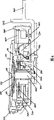
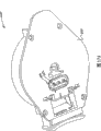
Fig. 1 is the axonometric drawing of overlooking of paster shape syringe or infusion system first embodiment, and syringe among the figure or infusion system have adopted the side button, and what represent among the figure is at the state of executing before and triggering;
Fig. 2 be adopt the paster shape syringe of side button or infusion system first embodiment look up axonometric drawing;
Fig. 3 is the vertical view that adopts first embodiment of the paster shape syringe of side button or infusion system;
Fig. 4 is the side elevation view that adopts first embodiment of the paster shape syringe of side button or infusion system;
Fig. 5 is the upward view that adopts first embodiment of the paster shape syringe of side button or infusion system;
Fig. 6 is the profile (along 6-6 lines among Fig. 1) that adopts first embodiment of the paster shape syringe of side button or infusion system;
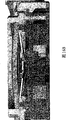
Fig. 7 is the cutaway view of first embodiment of the paster shape syringe that adopts the side button or infusion system being done from first perspective view (along 6-6 lines Fig. 1);
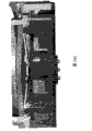
Fig. 8 is the cutaway view of first embodiment of the paster shape syringe that adopts the side button or infusion system being done from second perspective view (along 6-6 lines Fig. 1);
Fig. 9 is the cutaway view of first embodiment of the paster shape syringe that adopts the side button or infusion system being done from the 3rd perspective view (along 6-6 lines Fig. 1);
Figure 10 A is the decomposition view of the storage container subassembly in first embodiment shown in Figure 1;
Figure 10 B is the decomposition view of the housing subassembly in first embodiment shown in Figure 1;
Figure 10 C is the decomposition view of the button subassembly in first embodiment shown in Figure 1;
Figure 11 A is the profile (along 6-6 lines among Fig. 1) of first embodiment shown in Figure 1, and what this accompanying drawing was represented is at the state of executing before and triggering;
Figure 11 B is the profile (along 6-6 lines among Fig. 1) of first embodiment shown in Figure 1, and state shown in the figure is corresponding to executing after the energy but the situation before triggering;
Profile among Figure 11 C (along 6-6 lines among Fig. 1) has been represented the state of first embodiment shown in Figure 1 after triggering;
Partial sectional view among Figure 12 has been represented stream shown in Figure 10 A and storage container subassembly;
Graphical presentation among Figure 13 the example of relevant insulin stability data, this example is directed to storage container subassembly according to an embodiment of the present invention;
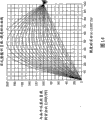
Graphical presentation among Figure 14 example according to an embodiment of the present invention, relevant disc spring statistical data;
Axonometric drawing among Figure 15 A has been represented a kind of preferred implementation of many patients of syringe needle contact surface structure, and this many patients contact surface structure designs for patient's syringe needle manifold;
Axonometric drawing among Figure 15 B has been represented the another kind of patient's contact surface structure for patient's syringe needle manifold design shown in Figure 15 A.
Axonometric drawing among Figure 16 A has been represented Figure 10 A another embodiment to each subassembly shown in Figure 10 C, and these subassemblies are in the state after part is assembled among the figure;
Cutaway view among Figure 16 B has represented that each subassembly shown in Figure 16 A is at the state of executing before and triggering;
Cutaway view among Figure 16 C has represented that each subassembly shown in Figure 16 A is at the state of executing after and triggering;
Axonometric drawing among Figure 17 A has been represented rotary insurance shade mechanism according to an embodiment of the present invention, and what represent among the figure is at the state of executing before and triggering;
Axonometric drawing among Figure 17 B has been represented rotary insurance shade mechanism according to an embodiment of the present invention, represent among the figure be execute can, trigger and leave the user skin surface after state;
Axonometric drawing among Figure 18 A has been represented extension insurance shade mechanism according to an embodiment of the present invention, and what represent among the figure is at the state of executing before and triggering;
Axonometric drawing among Figure 18 B extension insurance shade mechanism according to an embodiment of the present invention, represent among the figure be execute can, trigger and leave the user skin surface after state;
Figure 19 A is the decomposition view that adopts second embodiment of the paster shape syringe of side button or infusion system;
Axonometric drawing among Figure 19 B has been represented the patient's syringe needle in second embodiment/barrier film syringe needle manifold system shown in Figure 19 A;
Figure 19 C is the cutaway view to second embodiment shown in Figure 19 A, represent among the figure be execute can with the state before triggering;
What the cutaway view among Figure 19 D was represented is that second embodiment shown in Figure 19 A is at the state of executing after and triggering;
Figure 20 A is the decomposition view that adopts the 3rd embodiment of the paster shape syringe of side button or infusion system;
What the cutaway view among Figure 20 B was represented is that the 3rd embodiment shown in Figure 20 A is at the state of executing before and triggering;
What the cutaway view among Figure 20 C was represented is that the 3rd embodiment shown in Figure 20 A is at the state of executing after and triggering;
Figure 21 A is the decomposition axonometric drawing that adopts the 4th embodiment of the paster shape syringe of overhead button or infusion system;
What the partial sectional view among Figure 21 B was represented is that the 4th embodiment shown in Figure 21 A is at the state of executing before and triggering;
What the cutaway view among Figure 21 C was represented is that the 4th embodiment shown in Figure 21 A is at the state of executing after and triggering;
Figure 22 be one about data instance at external execution infusion, this accompanying drawing has been represented the variation of flow rate in 38 hours time range;
Figure line among Figure 23 has been represented the example of relevant blood sugar concentration data;
Figure line among Figure 24 has been represented the example of insulin concentration data in the relevant blood;
Figure line among Figure 25 has been represented the example of relevant insulin reflection data; And
Figure line among Figure 26 has been represented an example of relation data between pressure and the institute's delivered volume.
In whole accompanying drawings, identical number designation will be considered to refer to same base part, device or structure.
The specific embodiment
Draw opinion
Hereinafter each embodiment of the present invention that will describe can be used as a kind of shape of paster easily device, is used for carrying the material of predetermined close-for example medicine or medicine by a bonding injection device that adheres to user.Described device is autonomous complete, and by be arranged on the bottom surface bonding agent and on the skin surface attached to user.Device is in case by the correct location of user and after triggering, act in the device the lip-deep pressure of a storage container by a d/d disc spring and will be used to the content in the flexible storage container through the emptying of one or more micropin head, a plurality of syringe needles are wherein provided by a syringe needle manifold.Then, utilize by in the device push into micropin head in the skin with one or more springs, the material in the storage container is penetrated the skin of user and is carried into.Be understood that: other embodiment also is feasible, in these embodiments, replaces disc spring with dissimilar energy storage devices, and other energy storage device can be mechanical, electromobility and/or chemical.
Those skilled in the art will be appreciated that: exist multiple mode to implement paster shape syringe disclosed herein or infusion device system.Although with reference to the accompanying drawings with description in the embodiment introduced the present invention is described, embodiment disclosed herein and do not meant that disclosed invention covering scope exhaustive in all optional design form and embodiments.In disclosed each embodiment, device all is called as infusion device, and still, device also can be according to the faster speed injection mass of the medication rate that generally can realize than infusion device device.For example, device can be short to several seconds or long arriving in several days time content execution conveying.
Basic structure
At Fig. 1 in first embodiment of the invention shown in Figure 11, one injection device 1000 comprises a storage container subassembly 100, and this subassembly comprises a upper shell 110, a storage container substrate 120, at least one disc spring 130, a latch 140, fills plug 150, barrier film 160 and storage container thin film 170.Injection device 1000 also comprises a housing subassembly 200, and this subassembly comprises a lower house 210 and patient's syringe needle manifold 220, and manifold 220 wherein has an at least one patient's syringe needle 222 and a manifold diaphragm 224.Housing subassembly 200 also comprises a syringe needle shade 230, syringe needle shade driving spring 232 and an adjustable needle medicated cap 240.Be provided with an adhesive linkage 250 on the bottom surface of lower house 210, this adhesive linkage is covered with by one deck removable film (not shown), also is provided with a drawing handle 260 on the bottom surface.Can adopt that a buckle 270-for example " E " shape buckle is fixed to latch 140 on the drawing handle 260.Injection device 1000 also comprises a button subassembly 300, and it comprises at least one syringe needle manifold driving spring 310, a button sliding part 320, at least one barrier film syringe needle 330, a barrier film needle sheath 340 and one fluid communicating pipe 350 of cover.An available push button panel 360 packaged button subassemblies 300.In the following description, the general description with " storage container " speech is assembled into together and storage container substrate 120 that constitute a separate component, filled plug 150, barrier film (body) 160 and storage container thin film 170 in the storage container subassembly 100.
As mentioned above, for ease of describing, hereinafter, Figure 10 A can be classified into several subassemblies to each composition member of 10C illustrated embodiment.These subassemblies include, but is not limited to storage container subassembly 100, housing subassembly 200 and button subassembly 300.Fig. 1 has represented embodiment after the present invention's one assembling to Fig. 5, and Fig. 5 represented exemplary cross-section structure to Fig. 9.
To shown in Figure 5, embodiments of the present invention 1000 can be made of these subassemblies as Fig. 1, thereby form a paster shape, wearable, autonomous complete material injection device, and this device can be used to carry various medicaments to the patient.As among Fig. 1 shown in the state of executing before and triggering, before using and in the use, patient's syringe needle of device 1000 is hidden, and device can be fixed on the patient body by a bonding plane.Can pressurize to the content in the storage container by drawing handle 260 is removed, finish " execute can " operation with this to content in device and the device, then can be by applying suitable power so that patient's syringe needle falls to button 360, be communicated with thereby between storage container and syringe needle, form fluid, and then will install " triggering ".In the case, device 1000 is convenient to carry out self-injection, and can eliminate or reduce the difference aspect injection technique between the different users.
Fig. 1 is the axonometric drawing of overlooking of injection device 1,000 first embodiments.In Fig. 1, the upper shell 110 and the lower house 210 that have assembled are showed respectively, and button subassembly 300 is arranged between the upper and lower casing.Among the figure, drawing handle 260 (hereinafter will be described in detail) is represented as and is in the state of executing before, triggering, and it is used for latch 140 is fixed on device, and the button 360 of screening, and makes it can not be subjected to the effect of external force.Can be clear that more that from Fig. 2 (this accompanying drawing is the axonometric drawing of looking up of first embodiment) drawing handle 260 also by buckle 270 and needle cap 240 and latch 140 interlockings.In addition, shown in Fig. 6 (it is the profile of first embodiment being done along 6-6 lines among Fig. 1), drawing handle 260 also with 320 interlockings of button sliding part.Fig. 3 is the vertical view of first embodiment, its represented button sliding part 320 and the device that need be triggered between the position to positive relationship and shift motion.Fig. 4 is the side view of first embodiment, has expressed the profile of device and the centering location of patient's syringe needle perforate, and the upward view of first embodiment can be more clearly visible the perforate of described patient's syringe needle from Fig. 5.
Fig. 6 is a plurality of profiles (doing along 6-6 lines among Fig. 1) of first embodiment to Figure 11 C to Fig. 9 and Figure 11 A, these profiles represented each subassembly before executing energy/triggering in the state and subsequently execute structure, location and operation in the state of energy/triggering back, will be introduced respectively these subassemblies in the independent chapters and sections of below each.
The storage container subassembly
In Figure 10 A, represented the storage container subassembly 100 of injection device 1000, it is with one or more non-expansibilities but have flexible thin film 170 and combine by a rigid element 120.Storage container subassembly 100 can be contained in multiple material between first, second thin film, perhaps is contained between the first film and the rigid element, and wherein under the former situation, first or second thin film also is oriented to pasting rigid element.
As will be described in detail, rigid element 120-or the storage container substrate can constitute by hard material, and as the hard part of storage container, flexible thin film 170 can be attached on this hard part.Can more be clear that from Fig. 6, rigid element 120 can have the center protruding segments 122 and a flange 124 of a dish type, flange 124 is configured to the periphery around rigid element, so that fexible film 170 or the heat-sealing of thin film cover can be received on the rigid element, thereby between the two, form a storage chamber or chamber.Storage container subassembly shown in Figure 10 A also can provide a guiding piece perforate 112, is used to connect a guiding piece 126, so that can utilize arbitrarily technology (for example ultrasonic locating technology) accurately to locate and connect rigid element 120 and upper shell 110.
As mentioned above, the storage container in Figure 10 A illustrated embodiment can be designed to like this: it preferably has the coverboard or the hard inner surface of a hard, and has at least one fexible film, and thin film is attached around the edge of hard coverboard or inner surface.Fexible film 170 can be heat-sealed to be received on the rigid element 120, thereby forms a chamber or capsule bag, is used for the content of storage device.At least one plate of facing the wall and meditating of chamber comprises a fexible film 170, and one or more disc springs 130 can be arranged in fexible film 170 near, be used for applying the pressure of substantial constant, and to storage container chamber and content pressurization to fexible film.
Shown in Fig. 6 and Figure 10 A, disc spring 130 is configured to apply even basically and constant compression force to the fexible film 170 of storage container subassembly 100, thereby to the pressurization of the content between fexible film 170 and rigid element 120 in the storage container, to force content from storage container, to flow out through one or more stream, Figure 12 has at length represented stream wherein, and this accompanying drawing is the partial sectional view that the runner shown in Figure 10 A and storage container subassembly are done.As mentioned above, storage container shown in Figure 10 A also can be made of the fexible film of two or multi-disc non-expansibility, in the case, content can be accommodated between two thin film, and wherein at least one thin film is attached on the rigid element 120, to form a rigid substrates, be used for the content of storage container is carried out compression and pressurizeed.In an embodiment again of storage container subassembly 100, flow rate is adjusted on one or more levels low flow rate level that reduces step by step automatically by the high flow rate when initial.Other detail content of relevant Flow-rate adjustment can be further referring to No. 10/396719 (serial number) U.S. Patent application, this application was submitted on March 26th, 2003, its name is called " multiple stage fluid conveyer device and method ", and the full content of this application all is incorporated among the application as a reference.
The fexible film 170 of storage container subassembly 100 can be made by material that does not have extensibility or laminated body-for example metal-coated thin film or other similar material.For example, storage container subassembly in first embodiment can use a kind of like this flexible overlapping thin film: it is to be made of one first polyethylene layer, one second chemosphere, one the 3rd metal level and one the 4th layer, wherein, described second chemosphere is known to those skilled in the art, it is used to provide a kind of connection mechanism, so that be connected with the 3rd metal level,, the selection of the 3rd metal level carries out the 4th layer or can or can constitute and being based on barrier properties by polyester by nylon.By adopting metal lining thin film or the metallized film 170 cooperate with rigid element 120, can improve the barrier properties of storage container, the pot-life of the content that can increase thus or prolong wherein to be held.For example, content at storage container comprises under the situation of insulin that the contact raw material in the storage container subassembly 100 of above-mentioned embodiment comprises linear low density polyethylene (LLDPE), low density polyethylene (LDPE) (LDPE), cyclic olefine copolymer (COC) and polytetrafluoroethylene.As described in detail below such, the contact raw material of all the other runners of content comprises polyethylene (PE), medical grade polypropylene thing and rustless steel in the storage container.Those will preferably authenticate by ISO10-993 with the contacted material of content in the storage container subassembly, perhaps by other suitable biological adaptation property testing.
It is further preferred that the storage container of storage container subassembly 100 can be preserved prescribed time-limit with content in suitable controlled environment, and can not cause adverse effect, and this storage container can be applied under the various environmental conditions content.In addition, the iris action of being realized by each parts of storage container does not allow gas, liquid state or solid-state material to penetrate in the content or from content with certain ratio to discharge, and this ratio that is not allowed to is meant that it is greater than for meeting the permeability that the required shelf-life allows.In the embodiment shown in Figure 10 A, the material of storage container subassembly can be deposited in the temperature range of about 34 to 120 degrees Fahrenheits and work, and has the useful life more than 2 years.For example, as shown in figure 13, between the operating period of apparatus of the present invention, above-mentioned storage container subassembly to the stability of insulin without any influence.Graphical presentation among Figure 13 the example of insulin stability in the storage container subassembly shown in relevant Figure 10 A.
In Figure 13, the stability of storage container content-insulin is represented as insulin level concentration on the Y direction, and result shown in the figure is corresponding to the result in six insulin storage capacitance devices are during 25 days (or more natural law).Each device that compares comprises 4cc storage container, a 25cc storage container and a 37cc storage container of first embodiment of the invention, and comprises a 4cc, a 25cc, 37cc glass medicine bottle insulin storage capacitance device.As shown in figure 13, the variation of the insulin concentration in the stable sample in during 25 days is very little, and in the identical time, and the difference between each device legend is very little or not there are differences.Except the requirement of satisfying stability, storage container has also been guaranteed service behaviour by successfully having passed through multinomial leak-testing, and leak-testing wherein for example is sample was kept 20 minutes under 30psi pressure and not have a leakage.From the said structure of storage container subassembly can obtain some other relate to filled, deposit and the advantage of conveying aspect, these advantages comprise: headspace reduces and has strengthened the suitability, hereinafter will do more detailed description to this.
As will be discussed in more detail below, before filling, the storage container of storage container subassembly 100 is preferably and is in emptying state.By before filling with the storage container emptying shown in Figure 10 A, and make the hard plate of rigid element 120 only have slightly depression 122, can reduce headspace, and can eliminate the excessive waste material in the storage container.In addition, the shape of storage container can be designed to adapt to employed execute can mechanism type-for example have the dish spring or the disc spring 130 of multiple diameter and height dimension.In addition, in filling process, use the flexible storage container of emptying can reduce storage container and be filled back contained air or bubble.If device is subjected to external pressure or influence of temperature variation, adopt flexible storage container also can bring very big benefit, wherein, the effect of external pressure or variations in temperature will cause the increase of storage container.In the case, flexible storage container can be with its content to expand and shrink, can prevent thus since expansive force or contractility act on fill fill in 150 and barrier film 160 on leak.This also helps to eliminate the dose variations that occurs owing to variation of ambient temperature and pressure oscillation.
As mentioned above, be positioned at rigid element 120 lip-deep dolly dimples 122 and help to prevent such situation: under the pressure effect of disc spring 130, owing to storage container thin film 170 is collapsed to form and held fluidic cave bag.Above-mentioned depression also helps to realize such effect: by providing a fluid flow passage with regard to inflatable storage container system, reason is: preferably, fluid is incorporated in the device can before with system evacuation.Can when manufacturing installation, finish fluidic feeding operation, perhaps also can before being about to, carry out infusion again by end user's use.For example, in a kind of filled method, can utilize to fill mouthful 152 pairs of storage containers execution emptyings, and then a filled plug 150 is set.As alternative, in second kind of filled method, before using, can then a filled plug 150 be set earlier with the storage container emptying, then fill by filling 150 pairs of storage containers execution of plug again.Such design makes the storage container of device can be incorporated in medicine according to certain mode and fills the place, place, realizes aseptically filling with this, and reduced headspace, and the aseptic that has kept fluid flowing path to connect.
Another feature of storage container subassembly 100 comprises such ability: carrying out the automatic check that can realize when filling the dirt microgranule, perhaps allow user to check in use.One or more barriers of storage container-for example rigid element 120 can form with transparent, limpid plastic material is molded, so just can observe the material that holds in the storage container.Transparent, limpid plastic material is preferably cyclic olefine copolymer, this material be characterised in that have very high transparency and limpid degree, contractility is poor and the material that holds in storage container has biocompatibility.Under these circumstances, the characteristic body that has on the storage container is minimum, and these characteristic bodies may hinder the observation (that is to say that characteristic body allows to be rotated at least in the process of checking) to material.
Fluid passage
The rigid element 120 of storage container subassembly 100 shown in Figure 10 A also comprises at least one as shown in figure 12 fluid passage 128, and this stream leads to the main chamber 127 of storage container.In embodiment shown in Figure 12, stream 128 is drawn from the main chamber 128 of storage container, pass or wear down along rigid element 120 peripheries heat-sealable area that be provided with, that be used for fixing fexible film 170, and be passed into one in the chamber 129 that fills between screw plug 150 and the barrier film 160, thereby allow the fluid in the storage container to flow to barrier film 160 from storage container.In embodiment shown in Figure 12, stream 128 preferably is manufactured into and can reduces dead volume, and has the geometric construction that can admit filled head, hereinafter will be described in detail to this.
Table 1
| The ingredient of stream | Material |
| Storage container | Polyethylene, cyclic olefine copolymer and/or polytetrafluoroethylene |
| The storage container thin film | The thin film of metal lining, the thin film of forming by polyethylene, aluminum, the polyester that has the chemical bonding layer and/or nylon for example, the product A of making such as Beacon Converters 83 by Saddle Brook place, New Jersey |
| Barrier film | Halobutyl rubber |
| The barrier film syringe needle | Rustless steel |
| Barrier film syringe needle manifold | Polyethylene and/or medical grade polypropylene |
| Body | The polyethylene that has PVC skin and vinyl acetate resin tack coat |
| Patient's syringe needle manifold | Polyethylene and/or medical grade polypropylene |
| Patient's syringe needle manifold thin film | The |
| Patient's syringe needle | Rustless steel |
Specifically, available rustless steel is made patient's syringe needle 222 and barrier film syringe needle 330, barrier film syringe needle manifold 322 and patient's syringe needle manifold 320 available polyethylenes and/or medical grade polypropylene manufacturing, available halobutyl rubber is made barrier film 160, and the polythene material of the available PVC of having skin and vinyl acetate resin tack coat is made the flexible pipe 350 between barrier film syringe needle and/or barrier film syringe needle manifold and the patient's syringe needle manifold.Those will be preferably test by the relevant biocompatibility of ISO10-993 with the contacted material of the content in the storage container subassembly.
As hereinafter introducing in detail, barrier film syringe needle 330 can be 25-29 specifications for example much larger than patient's syringe needle 222, is beneficial to easily operate, and can prevents that convection cell from causing obstruction.Can be clear that more that from Figure 10 C and Figure 12 the size of barrier film needle sheath cover or body 340 is designed to: will be before plug 160 pierce through at barrier film syringe needle 330, it matches with the depression aperture 342 that elastomer forms in plug 160.Barrier film needle sheath cover 340 forms a gnotobasis with elastomer forms depression aperture 342 in plug 160 this binding energy, barrier film syringe needle 330 will pass through this gnotobasis when piercing through sheath cover and barrier film, thereby the barrier film syringe needle can be exposed under the collarium border at no time.
Fill the head end mouth
Return and come referring to Figure 10 A and Figure 12, also can fill head end mouth 152 through one and lead to chamber 129 between barrier film 160 and the storage container, filled head end mouth 152 wherein is arranged in the storage container subassembly, and can fill a blocking 150 by one and close.Filling a blocking 150 can be identical parts with barrier film 160, and this can further reduce the complexity of manufacturing.
Owing to be provided with filled head end mouth 152, allow to have finished afterwards and/or powder charge more in use by the assembling that execution fills-installs to storage container of outside medicine source even install.According to first kind of filled method, a device that assembles fully can be set, have only fill plug 150 by plug in filled head end mouth 152, utilizing after a filling device fills with storage container, set up one again and fill a plug or a filled blocking.As alternative, in second kind of filled method, device is assembled fully, it fills a blocking 150 and also is arranged in filled head end mouth 152, but this device is not powder charge as yet, afterwards, uses a standard syringes or similar device through filling a blocking medicinal liquid to be injected.Because the top of storage container is to make with bright material, can easily sees filling liquid level and unnecessary air, and utilize above-mentioned syringe that air is pumped out.In this manner, just can realize filling the accurate control of volume and delivered dose.
For the injection device of powder charge in advance, fill head end mouth 152 and be provided with filled screw plug 150, it is with port one 52 sealings.Then, can utilize upper shell 110 will fill screw plug 150 fix in position, and prevent that blocking 150 from deviating from, can also operate filling screw plug simultaneously, fill so that carry out when needed.Allow the device of powder charge in use for those, fill head end mouth 152 and keeping the ability that can be connected, or realize this connection by means of above-mentioned filled screw plug 150 or by means of an inner collar, the collar has wherein replaced the filled screw plug that is removed.In these above-mentioned two kinds of filled situations, filling head end mouth 152 makes fluid flow into the main chamber 127 of storage container subassembly 100 through above-mentioned stream 128 from an outside medicine source, the storage container subassembly also can comprise input port and output port, fills to help carrying out.
For the situation of just carrying out powder charge in use, device need not to carry out some set up procedures, and these steps are at length listed hereinafter.If device is to fill in use, then just need not to utilize latch 140 that disc spring 130 is remained on the advanced position, reason is: the pressure that is acted on the sky storage container by d/d disc spring will can not produce any effect.To have the effect that disc spring 130 is applied displacement to filling of carrying out of device in use, in case outside fill pressure source remove with being communicated with of storage container after, spring just can freely pressurize to the storage container subassembly, and content is extruded from storage container.In addition, that carries out in use should fill operation and can finish the sterile packaged step, can not be subjected to having the restriction of the existing defective of device of medicine.
Disc spring
Shown in Figure 10 A, disk spring or disc spring 130 are comprised in the device 1000, are used for applying even basically, constant active force to storage container, and so that content is extruded from storage container, hereinafter, this spring also often is called as " constant force spring ".Constant force spring 130 is used to storage power, and in use, when discharging this energy when flip flop equipment, it can be exerted pressure to storage container.Spring 130 is remained on deflected by a pin 140, and pin 140 is positioned at the center of a plurality of spring detents.Adopt such design, in depositing process, spring can be to thin film 170 or all the other any member stress applications of storage container subassembly 100.
Pin or latch 140 can be any suitable pin rod, body or ring body, and its rigidity is enough to the tension force and the distortion of antagonistic spring, and this latch is fixed on the cancel system, and cancel system wherein for example is the drawing handle of hereinafter describing in detail 260.Under normal drag load, latch 140 should not lose efficacy, or, should not disintegrate under the stress condition of a certain parts of assembly when transportation or carrying, if not, false triggering will appear.
Shown in Figure 10 B, be provided with drawing handle 260, so that remove above-mentioned latch 140.Drawing handle 260 is set near the bottom surface of device, and it comprises one or more members, and these members extend the side to device, is formed with to be beneficial to the frame for movement of removing latch 140.In the embodiment shown in Figure 10 B, drawing handle 260 comprises a member 262, and it extends the button head 360 to button subassembly 300, and this button head of screening.With this understanding, 260 preventions of drawing handle apply active force to button 360, are removed just passable until it.So just can prevent before correct location because pushing button and unexpected flip flop equipment.
In the above-described embodiment, drawing handle 260 comprises a member, and it can prevent to apply active force to button.In other remodeling of this embodiment, the drawing handle comprises a member, and it extends between button and the device case, moves when being subjected to the external force effect to stop button.
Other drawing handle/button mutual interlocking gear also can be set between drawing handle 260 and needle cap 240 and latch 140,, prevent unexpected the triggering to guarantee correct operation.For example, in Figure 10 B, drawing handle 260 also comprises member 264, and it is from the drawing grip surface extends to perforate the button sliding part 320, move sliding part-and be removed just and allow to prevent to affact power on the button 360, thereby prevented false triggering up to the drawing handle.
In another modification of above-mentioned embodiment, button and button sliding part self just have the effect that discharges latch.In this remodeling, when button was triggered, latch departed from its attitude that is substantially perpendicular to disc spring.Along with the further deflection of latch, its final and disc spring disengaging.The removal of drawing handle 260 also can be accompanied by sense of touch harmony snap to be shown, to provide feedback to user.
When latch 140 is drawn out and removes constraint to disc spring 130, the spring detent of spring will fall, and in the case, spring detent has applied pressure to the thin web of storage container subassembly 100.The edge of spring 130 is sandwiched between storage container and the upper shell, and be designed in storage container, produce and be preferably 1 to 50psi pressure, this pressure more preferably about 2 to 25psi, most preferably about 15 to 20psi, be transported in the cortex with this content storage container.For the situation of subcutaneous injection or infusion, just enough about 2 pressure that arrive in the 5psi scope.
The size of disc spring can be designed to its diameter in 1.15 to 1.50 inches scope, is preferably 1.26 inches, to finish the infusion to 600 μ l medicines.As shown in figure 14, can utilize and well known to a person skilled in the art that common disc spring calculates the spring geometric properties that figure line comes calculating optimum.As shown in figure 14, the multiple bar chart line among the figure has been represented the load-amount of deflection feature figure line of the multiple Belleville washer that height/thickness rate is different.As known in the art, Belleville washer or disc spring show certain load characteristic, and this characteristic is represented as: the relation that moves to the stroke of relaxation state from flat or deflected with the percentage ratio and the spring of flat position load deflection.As shown in figure 14, the spring of optional usefulness with certain height/thickness ratio realized required load-amount of deflection model.
The housing subassembly
Return and come, be provided with a bottom or lower case 210 and match with above-mentioned upper shell 110 and storage container subassembly 100 referring to Figure 10 B.Lower house 210 can be used to seal any remaining member, and can provide the riveting clamping structure to hold and be connected each parts and housing member.Lower house 210 also can comprise one or more guide structures, is used for fixing, release and call-on button sliding part 320 and patient's syringe needle manifold 220, and syringe needle manifold wherein will be explained in detail hereinafter.Unit two-for example the demarcation line between the housing unit can be arranged near the vertical centre that installs up and down, this will form more stable assembly, reason is: like this, the button subassembly that hereinafter will describe can top down be pressed in the firm housing, rather than is forced on the plate body.Upper shell 110 and lower house 210 can utilize snap fit to couple together, or utilize method for ultrasound welding to join to together.
In addition, upper shell 110 and lower house 210 can also adopt independently subassembly parts, and in the case, each parts can be autonomous complete, and are stable.For example, the storage container that has assembled is exactly independently parts, particularly, it comprises the storage container substrate 120 in the storage container subassembly 100, filled plug 150, barrier film 160 and storage container thin film 170, this individual components does not have any unnecessary element, the result is exactly to reduce the filling dirt particulate loading of sneaking in the operation.In addition, all energy storage components are installed with can both being independent of storage container, thereby in the process of filling, can not discharge these energy storage components unintentionally.
The micropin head
Return and come referring to Figure 10 B and Figure 10 C, represented device also has at least one patient's syringe needle 222-or micropin head among the figure, but also can have a plurality of syringe needles, and three micropin heads for example have been installed in button subassembly 300 shown in Figure 10 C.Each micropin head 222 preferably is at least specification or littler No. 31, for example can be No. 34 syringe needles, and syringe needle is anchored in patient's syringe needle manifold 220, and this manifold 220 can be configured to be connected with storage container.Each micropin head all is fixed, and is in office how less than deviating from from manifold 220 under 1 pound the power effect to prevent.If in device, be provided with a plurality of micropin heads 222, then these micropin heads can have different length or specification, perhaps length is all different with specification, and one or more apertures can be set along the length of needle body, the aperture of syringe needle be preferably located in terminal near, if the end of syringe needle is an inclined-plane, then the aperture is near this end inclined-plane.
In the above-described embodiment, adopt a plurality of No. 34 syringe needles to carry that content will be feasible in the storage container, reason is that the used time of infusion process will be longer than usually with syringe and carries out used time of injection immediately that injection for curing needs very big intubate or syringe needle.In disclosed embodiment, can adopt any micropin head, these syringe needles will be used to carry out Intradermal infusion or hypodermoclysis; But to (for example equaling 2mm) between the 4mm, and the alignment placement of these patient's syringe needles can be linear or non-linear to the protruded length of micropin head, and the syringe needle of arbitrary number can be set according to concrete applicable cases at 1mm in the embodiment shown in Figure 10 C.
The button subassembly
Represented a button subassembly 300 among Figure 10 C, this subassembly becomes one a barrier film syringe needle 330, barrier film syringe needle manifold 322 and button sliding part 320; But also can adopt following design to come the manufacturing of simplified push button subassembly 300: a button snap-on panel 360 is set, and it can make one or more parts of button be simplified.Button sliding part 320 has also formed the mechanism that patient's syringe needle manifold can be fixed on the punctured position, and when device was correctly triggered, this mechanism can discharge manifold.
Shown in Figure 10 C, body 350 is used to form a stream (hereinafter will describe in detail), the junction of the junction of this body and barrier film syringe needle manifold 322 outlets and itself and 220 imports of patient's syringe needle manifold is positioned at the same side, be beneficial to assembling, and can between barrier film syringe needle manifold and patient's syringe needle manifold, form flexible stream.The patient's syringe needle manifold 220 that has patient's syringe needle 222 is assembled in the guide rail 324 that is provided by button sliding part 320, thus formed one can stably fix, and releasable mechanism, hereinafter will be described in detail this mechanism.
Shown in Figure 10 C, be provided with a pair of card key 326,328 along guide rail 324, be used for button sliding part 320 is positioned at different gears or position.For example, the button subassembly 300 shown in Figure 10 C has a plurality of operating positions, is provided with for storage container powder charge, patient's syringe needle/barrier film needle assembly, welded case and user trigger respectively.Specifically, be provided with at least three operating positions.
Primary importance or assembling position are to weld and be provided with in order to carry out to storage container execution powder charge with to housing.Because patient's syringe needle manifold 220 sliding motions with respect to button sliding part 320 are maintained fixed, so primary importance is configured to like this: on this position, the groove 221 of patient's syringe needle manifold engages with first group of card key 326 on the button sliding part 320.On this position, can carry out powder charge, and can not interfere between barrier film needle sheath cover 340 and the barrier film 160.
The second position or shipping position are in order to transport and to realize that the barrier film needle sheath cover 340 and the sealing of barrier film 160 are provided with.Because 220 slips with respect to button sliding part 320 of patient's syringe needle manifold are maintained fixed, so, along with the button sliding part engages slidably, groove 221 on patient's syringe needle manifold and first group of card key 326 are separated from, but still be positioned in the guide rail 324, engage with second group of card key 328 of button sliding part 320 more subsequently, so just can reach the second position.On this position, barrier film needle sheath cover 340 engages with elastic diaphragm plug 160 formed pit-holes 342, and at this moment, elastomeric plug 160 is not pierced through by barrier film syringe needle 330 as yet.This engagement relationship between barrier film needle sheath cover and the pit-holes has formed a gnotobasis, and the barrier film syringe needle is this gnotobasis of process when piercing through sheath cover and barrier film.Thereby barrier film syringe needle 330 can be exposed in the collarium border at no time, and this can eliminate the influence that weld local field far away effectively.
The 3rd position is set to trigger position or use location.Because 220 slips with respect to button sliding part 320 of patient's syringe needle manifold are maintained fixed, so, along with the button sliding part engages slidably, groove 221 on patient's syringe needle manifold and second group of card key 326 are separated from, but still be positioned in the guide rail 324, up to guide rail on opening 325 aligned position, it drops away from button sliding part 320 and becomes free state subsequently.On the 3rd position, barrier film 160 is pierced, and manifold and insurance institution (all describing in detail hereinafter) are released, and are pressed to the skin surface of user by spring 310.In the illustrated embodiment, in shifting to the 3rd position process, pierce through barrier film 160, to barrier film syringe needle 340 pressurization and discharge the required active force of patient's syringe needle manifold 220 usually between 2 to 4 pounds.
Patient's needle assembly 220 can both be introduced with barrier film syringe needle 322 and discharge the fluid that holds in the storage container, and transports fluid in patient's syringe needle 222.Thereby each manifold housings all has many streams, is used for the content that transports from barrier film syringe needle 330 or other protruding top body and associated pipe 350 is carried out drain, and content is flowed to patient's syringe needle 222, thereby be input in the skin of user.Wherein anchoring patient's syringe needle manifold 220 that patient's syringe needle 222 arranged has the barrier film syringe needle manifold 322 of barrier film syringe needle 330 to keep streams to be communicated with by flexible pipe 350 with anchoring wherein.
Utilize button subassembly 300 and lower house 210, patient's syringe needle manifold 220 is maintained under the pre-release conditions or " upper " state that loaded by one or more springs 310.In the first kind of design form that patient's states manifold 220 is remained on above-mentioned upper state, patient's states manifold 220 is engaging one group of guide rail 324 making on the button sliding part 320 slidably.Owing to keep motionless in the notch 212 that patient's syringe needle manifold 220 is made on lower house 210, button sliding part 320 is shifted slidably, till guide openings 325 and patient's syringe needle manifold 220 are aligned, thereby make patient's syringe needle manifold 220 from guide rail 324, deviate from and drop in the notch.
At the second kind of design type that is used for patient's syringe needle manifold 220 is fixed on upper state, extend one or more projection (not shown)s on the button sliding part 320, these projections remain on syringe needle manifold 220 the upper state that is loaded by one or more springs 310.In the process that triggers, button sliding part 320 is shifted slidably, mobile projection and remove constraint to patient's syringe needle manifold 220, manifold is released and is guiding the skin surface of shifting to user by the structure that is provided with in lower house 210 and the button sliding part 320.Owing to the projection displacement has discharged patient's syringe needle manifold 220, manifold falls and syringe needle 222 is pushed up in the skin of user.Introduced other minutia of relevant supporting lug further at No. 60/420233 U.S. Patent application mentioned above, the full content of this application all is incorporated into herein as with reference to technology.
In two kinds of above-mentioned design forms, one or more driving springs 310 apply active force to the top of patient's syringe needle manifold 220, so that drive this manifold when flip flop equipment or with manifold during from upper release, thereby when manifold is released, can make patient's syringe needle 222 in place, thereby between barrier film syringe needle, barrier film syringe needle manifold, flexible pipe, patient's syringe needle manifold and needle array, form stream.The effect of driving spring 310 be by means of the patient's syringe needle manifold 220 that is subjected to its loading with syringe needle " implantation " in skin, wherein, the translational speed of manifold is in the scope of 15-26 miles per hours (6~12 meter per second).
The sliding motion of button sliding part 320 can also push barrier film syringe needle 330, makes it penetrate sheath cover 340 and barrier film 160, thereby form stream between formation stream storage container and barrier film syringe needle.The manifold 322 that has the barrier film syringe needle can be connected on the button sliding part 320, or be made into parts of sliding part, in triggering step, it is being followed the button sliding part and is moving together, up to make barrier film syringe needle 330 pierce through barrier film sheath cover 340, subsequently pierce through barrier film 160 again till.Depend on desirable order, can be before barrier film syringe needle 330 pierces through barrier film 160, delay and patient's syringe needle manifold 220 discharged and its seat is pressed onto on the skin surface simultaneously or a little, thereby patient's syringe needle 222 is thrust, make pressure fluid begin to flow into patient's syringe needle of patient's syringe needle manifold through barrier film syringe needle, barrier film syringe needle manifold, the flexible pipe that is connected with barrier film syringe needle manifold thus from storage container.
One or more barrier film syringe needles 330 (this and patient's syringe needle 222 have nothing to do) can be set, so that can strengthen the flow in the whole piece stream between storage container and the patient's syringe needle.In the above-described embodiment, the part of complete stream is two or more syringe needles, and specifically, this syringe needle is at least one barrier film syringe needle 330 and at least one patient's syringe needle 222.This just makes device to select heteroid syringe needle for use according to desirable flow path character.For example, patient's syringe needle 222 can comprise one or more No. 34 syringe needles, and barrier film syringe needle 330 can comprise one or more equal specifications or bigger syringe needle as required.In addition, patient's syringe needle and barrier film syringe needle are separately helped further improving the freedom of motion of patient's syringe needle in the device work process.
Available flexible pipe 350 couples together barrier film syringe needle 330 and/or barrier film syringe needle manifold 322 with patient's syringe needle manifold 220.The bent characteristic that softens of this body makes patient's syringe needle manifold 220 more freely to move with respect to the remaining part in the device, thereby realizes that more efficiently syringe needle takes a seat.Thrust in case correctly take a seat, patient's syringe needle manifold 220 just can form stream between the skin of flexible pipe 350 and patient's syringe needle 222 arrays and user.As mentioned above, the structure guiding that patient's syringe needle manifold 220 is set in the lower house 210 is in place, and above-mentioned driving spring 310 applied an active force to the top of patient's syringe needle manifold 220, so that syringe needle can be thrust when manifold is released.Driving spring has the plurality of optional form, and these forms comprise: use and lack to a helical spring, how to four helical springs, perhaps use one or more flat springs.
Figure 15 A and Figure 15 B have represented 220 1 kinds of detailed embodiments of patient's syringe needle manifold.Axonometric drawing among Figure 15 A has been represented a kind of preferred implementation for patient's syringe needle manifold 220 manifold contact surfaces design, that contact with the patient, and the axonometric drawing among Figure 15 B has been represented second kind of patient's contact surface structure.About other minutia of manifold can (it is submitted to day be on February 4th, 2003 referring to importing No. 10/357502 U.S. Patent application same assignee, that proposed by people such as Alex Lastovich with the application, name is called " apparatus and method that are used for carrying or extracting through skin material ") and the 60/447359th, 60/450680, No. 60/450681 above-mentioned U.S. Patent application, these apply for that disclosed content all is incorporated into conduct herein with reference to technology.
In the embodiment of Figure 10 C and patient's syringe needle manifold shown in Figure 15, for each patient's syringe needle 222 is provided with at least one fluid passage-or runner.Manifold can only have a stream that communicates with one or more patient's syringe needles, perhaps can have many streams or passage, with the independent drain dividually of content to each syringe needle.These streams or runner also comprise a zigzag section, so that can influence fluidic pressure and transfer rate when content is flowed through, play the effect of a reducer.Width, the degree of depth and the structure of runner or stream can change according to the application scenario in patient's syringe needle manifold 220, wherein, the width of runner between 0.015~0.04 inch, is preferably 0.02 inch usually, and is designed to reduce as much as possible the wasted space in the manifold.Can find out also that from Figure 10 C patient's syringe needle manifold 220 also can have a thin film cover plate 224, this diaphragm is to make with the material of listing in the table 1, is used to seal manifold and exposed manifold runner.Based on listed content in above-mentioned stream analysis and the table 1, the content that the material of diaphragm 224 also can be selected as and install is compatible fully, and its absorbability minimum, thereby produces microgranule still less.In the another kind of embodiment of patient's syringe needle manifold, manifold can seal without diaphragm, and in the case, the runner in the manifold body for example is interior envelope.
The skin contact of the manifold of patient's syringe needle shown in Figure 15 A 220 is surfaces that contact with skin, and it has a plurality of syringe needles that expose, and each syringe needle all stretches out from the needle stand 226 of a taper.Each tapered needle seat 226 all comprises one or more bonding trap ponds or close these trap ponds 228, so that patient's syringe needle 222 and patient's syringe needle manifold 220 are coupled together.Shown in Figure 15 A, it not is along whole circumference direction uniformity that the needle stand 226 of each patient's syringe needle is preferably, and can remove a part on the conical seat of syringe needle, and the size that this is a part of and the degree of depth are variable.It is in order to form glue bonding trap pond 228, perhaps to reserve the laser weld passage, be fixed in the tapered needle seat with the syringe needle with desired height that the needle stand 226 of patient's syringe needle is removed a sector or stripping and slicing, and makes syringe needle invade that the amount in the stream reaches minimum in the manifold.
Figure 15 B has represented the second kind pattern (only expressed contact surface) of patient's syringe needle manifold 220 with skin contact.Syringe needle conical seat shown in Figure 15 B has removed a fan awl district, and this position of removing part is identical with pattern shown in Figure 15 A, but its expanded range is between the above and below of patient's contact surface.But, in the pattern shown in Figure 15 B, also being provided with the depression that an awl contracts, it extends to the below of removing part on patient's pin nose-cone adapter, near the perforate of syringe needle.Thereby, be removed part and can shown in Figure 15 A be like that above patient's contact surface, along a scarce piece part of cone circumference, perhaps can be shown in Figure 15 B like that, it can be a bigger sector part on the cone circumference, it can extend in the manifold surface further, to form bigger gluing trap pond.
Above-mentioned be removed part and near depression can be used to from the front side patient's syringe needle 222 is bonded to patient's syringe needle manifold 220 in manufacture process, and be convenient to carry out the laser weld of the fixing of other type-for example.This front side adhesive method can reduce the height of manifold middle chamber, and the blunt end of syringe needle 222 extend in this chamber.The rough sledding that glue flow in the above-mentioned stream can have such problem: glue and medicine react, and form unknown in patient's syringe needle manifold 220 self and variable Dead space.Adopt the front side adhesive method can also improve the repeatability of technology, thereby can accurately calculate the small wasted space that causes by glue.But double check preferably should be passed through in this gluing location of carrying out on patient's contact surface shown in Figure 15 A and Figure 15 B, gathers into cima to prevent glue near the base portion of syringe needle, and this can reduce the protruded length of syringe needle.
Each subassembly in the above-mentioned embodiment is not to be restrictive, can design again it as required at given application scenario.For example, Figure 16 A has represented other embodiment of above-mentioned subassembly to Figure 16 B.Figure 16 A is Figure 10 A to the axonometric drawing of overlooking of another embodiment of subassembly shown in Figure 10 C, and among the figure, this subassembly is in the state that part assembles, Figure 16 B and 16C be respectively subassembly shown in Figure 16 A execute can and trigger before and afterwards cutaway view.Shown in Figure 16 A, lower house 180 can be designed to admit slidably incorporate button sliding part 182, and button sliding part 182 is similar with above-mentioned button sliding part 320, has a barrier film syringe needle 184.Patient's syringe needle manifold 186 of a broad also can be set, and it has at least one patient's syringe needle (not shown), and the bearing of trend of this manifold is parallel to the stroke directions of button sliding part, and has first, second driving spring 188.In the subassembly embodiment shown in Figure 16 A, barrier film syringe needle 184 and patient's syringe needle manifold keep being communicated with by a flexible pipe 190, allowing patient's syringe needle manifold can freely move (shown in Figure 16 C) after being disengaged constraint, flexible pipe 190 wherein is basically with above-mentioned identical.
In the embodiment shown in the 16C, button sliding part 320 joins that the type that can make whole device in the lower house 180 is wide further to realize low fasciation at Figure 16 A, can also improve operation in addition and creates conditions.In this embodiment, flexible pipe 190 is easier to distortion, thereby has further simplified the button sliding part.
Operation
Above-mentioned device is suitable for being used for to the various materials of patient's infusion, and these materials comprise medicine and medicament, and patient wherein refers in particular to human patients.In the linguistic context of this paper, medicament one speech comprises the material of biologically active, and this material can through the human body barrier film and the surface-especially skin be transported in the body.Hereinafter at length listed some examples of this material, it comprises antibiotic, antiviral agent, analgesic, anesthetis, anoretic, antiarthritic, antidepressants, hydryllin, anti-inflammatory agent, antineoplastic agent vaccine (comprising dna vaccination) etc.Can be infused into the component that patient's Intradermal or other subcutaneous material comprise human growth hormone, insulin, protein, peptide and these materials.Protein wherein and peptide can be natural formation, synthetic or reorganization forms.In addition, device can be used in the cell therapy, for example dendritic cell is being carried out in the process of Intradermal transfusion.
Can comprise medicine by other material that the present invention carries, vaccine, and other material, other material is used to prevent, diagnosis, alleviate, handle, or treatment disease, medicine wherein comprises α-1 antitrypsin, the angiogenesis medicament, antisensitizer, butorphanol, calcitonin ex hoc genus anne thing, Ceredase, the COX-II inhibitor, Dermatological Agents, dihydroergotamine, dopamine is made medication and antagonist, enkephalin and other calm class peptide, epidermal growth factor, erythropoietin ex hoc genus anne thing, follicle stimulating hormone releasing factor, G-CSF, glucagon, GM-CSF, the strong antiemetic of granisetron, growth hormone and analog (comprising growth hormone releasing hormone), the growth hormone antagonist, the hirulog of hirudin and hirudin analog-for example, the IgE mortifier, insulin, insulinotropic hormone and analog, the somatomedin of para-insulin, interferon, between leukin, lutropin, luteinizing hormone releasing hormone and analog, low-molecular-weight heparin, M-CSF, metoclopramide, the fan reaches the azoles logical sequence, monoclonal antibody, the narcotic analgesics, nicotine, the on-steroidal antiinflammatory, oligosaccharide, the ondansetron Bendectin, parathyroid hormone and analog, the parathyroid hormone antagonist, the prostaglandin antagonist, prostaglandin, the soluble recepter of reorganization, scopolamine, serotonin agonist and antagonist, sildenafil, terbutaline, thrombolytic agent, tissue plasmin activates foreign object, TNF-and the TNF antagonist, vaccine (with or without carrier/adminicle), vaccine wherein comprises that prevention and treatment antigen (include but not limited to subunit albumen, peptide and polysaccharide, polysaccharide conjugate, toxoid, the vaccine of heredity base, the nonactive intact cell that heavily assorts after the deactivation, virus, or bacillicarrier), these materials are relevant with following disease or cause of disease: addiction, arthritis, cholera, cocaine addiction, diphtheria, tetanus, HIB, Lyme disease, meningococcus, measles, parotitis, rubella, chickenpox, yellow fever, respiratory syncytial virus, the encephalitis B of band Cicadae heat, streptococcus pneumoniae, streptococcus, typhoid fever, influenza, hepatitis (comprises hepatitis A, hepatitis B, hepatitis C and hepatitis E), otitis media, rabies, poliomyelitis, HIV (human immunodeficiency virus), parainfluenza virus, rotavirus, the Epstein epstein-Barr virus, cytomegalovirus, chlamydia, atypical hemophiliac, Moraxella nasal mucosa inflammation, the human papilloma virus, pulmonary tuberculosis (comprising bacillus calmette-guerin vaccine), gonorrhea, asthma, arteriosclerosis, malaria, the E-escherichia coli, Alzheimer, H. pyloric bacteria, Salmonella, diabetes, cancer, herpes simplex, human papilloma and other similar substances, other material wherein comprises all medicines that are used for main treatment, the medicament that for example is used for the treatment of common cold, anti-addiction agent, antiabnormal reaction agent, antiemetic (anti-emetic), appetrol (anti-obesity), the osteoporosis agent, the infection agent, analgesic, anesthetics, the apositia medicine, anti-arthritic, anti-asthmatic, anticonvulsant, anti-tranquilizer, antidiabetic drug, hydryllin, anti-inflammatory agent, the migraine preventive, anti-motion sickness drug, the resisting emesis agent, antineoplastic agent, antiparkinsonian drug, pruritus, psychosis, antipyretic, the anticholinesterase agent, benzene phenodiazine antagonistic, vasodilation (comprises the whole body blood vessel, coronary artery, peripheral vessels, and cerebral blood vessel), the bone stimulant, central nervous system stimulant, hormone, hypnotic, immunosuppressant, muscle relaxant, parasympatholytic, parasympathomimetic agent, prostaglandin, protein, peptide, polypeptidase and other polymer, psychoanaleptics, tranquilizer, sexual hypofunction medicine and tranquilizer, the important diagnostic element-as tuberculin, and other hypersensitivity medicament, these materials are described in No. 6569143 United States Patent (USP), the name of this patent is called " method of material being carried out intradermal injection ", and its disclosed full content all is incorporated into herein as a reference.
Can from following set group, select by the vaccine dosage form that the present invention carries, this set group is by causing immunoreactive antigen or the antigen synthetic of human body to cause of disease, and these antigens or antigen synthetic are to make from following virus: HIV-1 (for example tat, nef, gp120 or gp160); Human toxoplasma virus (HSV), for example gD or its variant virus, or direct early protein matter-for example develop the ICP27 type virus of coming from HSV1 or HSV2; Cytomegalovirus (CMV-especially ethnic group virus-for example gB or its mutation); Rotavirus (virus that comprises reduced activity); Epstein epstein-Barr virus (for example gp350 or its mutation); Varicella zoster virus (VZV, gpI for example, gpII, and IE63), antigen or antigen synthetic or come from hepatitis virus, hepatitis virus B (for example B liver surface antigen or mutation) for example, hepatitis A virus (HAV), hepatitis C virus, the E Hepatitis virus, perhaps come from other viral pathogens, paramyxovirus for example: breathe and contain cellular virus (RSV, F for example, G albumen or their mutation), parainfluenza virus, Measles virus, mumps virus, human papillomavirus (HPV, HPV6 for example, 11,16,18), flavin virus (yellow fever virus for example, dengue virus, the Cicadae fever virus, Japanese encephalitis virus), or influenza virus (whole activity or inactivation of viruses, transformation influenza virus, the virus of in egg or mdck cell, growing, or the HA of all influenza virus particles or their purifying protein or recombiant protein-for example, NP, NA or M albumen, or the combination of these viruses), antigen or antigen synthetic or can make from bacterial pathogen, these bacterial pathogens for example are: eisseria, and this Pseudomonas comprises the N. neisseria bacteria, N. meningitis antibacterial (for example capsular polysaccharide and its conjugates, ferrum is in conjunction with transferrin, breast ferrum is in conjunction with transferrin, PilC, conglutnin); S. aurococcus (for example M albumen or its segment, C5A protease, fat techoic acid), S. agalactia (agalactiae), S. mutant; H. haemophilus ducreyi; Moraxella, this Pseudomonas comprise the scorching bacterium of M. nasal mucosa, and it is also referred to as the scorching bacterium (for example high molecular or low-molecular-weight conglutnin and invasion) of Branhamella nasal mucosa; Bordetella pertussis belongs to, and this Pseudomonas comprises B. pertussis antibacterial (for example pertactin, pertussis toxin, PT or derivatives thereof, thread hemagglutinin, adenyl cyclase, pili), B. parapertussis antibacterial and B. bronchus bacillus pertussis; Mycobacterium, this Pseudomonas comprise M. pulmonary tuberculosis bacterium (for example ESAT6, antigen 85A, B or C), M. bovista type, M. leprosy bacillus, M.avium, M. paratuberculosis bacterium, M. smegma (smegmatis); The legionnaires disease Pseudomonas, this Pseudomonas comprises L.pneumophila; Escherichia, this Pseudomonas comprises enterotoxin E. spirillum (for example the mucous colitis factor, thermal decomposition toxin or derivatives thereof, heat-stable toxin or derivatives thereof), enterorrhagia E. spirillum, cause enteropathy E. spirillum (for example will Hayes toxoid or derivatives thereof); Vibrio Pseudomonas, this Pseudomonas comprise V. cholera bacteria (for example cholera toxin or derivatives thereof); Shigella comprises S. bacterium sonnei (sonnei), S. dysentery bacillus, S. shigella flexneri (flexnerii); Yersinia comprises Y. enterocolitis (for example Yop albumen), the Y. plague, Y. pseudotuberculosis; The arcuation Pseudomonas comprises C. jejunum bacterium (for example toxin, conglutnin, invasion) and C. escherichia coli; Salmonella comprises S. typhoid fever bacterium, S. paratyphoid fever bacterium, S. cholera bacteria, S. gartner's bacillus; Listeria comprises L. unit cell plasmagene; The spiral Pseudomonas comprises H. pyloric bacteria (for example urease, catalase, VacA); Rhodopseudomonas comprises the P. aeruginosin; Staphylococcus belongs to, and it comprises S.aureus, S. epidermidin; Enterococcus comprises E.faecalis, E.faecium; The clostridium Pseudomonas comprises C. tetanolysin (for example tetanus toxin and derivant thereof), C. bacillus botulinus (for example Botulinum toxin and derivant thereof), C.difficile (for example A type or Type B clostridial toxins and derivant thereof); Bacillus, it comprises B. carbuncle (anthracis) (for example B. Botulinum toxin and derivant thereof); Corynebacterium, it comprises C. diphtheria bacterium (for example diphtheria toxin, diphtherotoxin and derivant thereof); The burgdorferi Pseudomonas, it comprises B.burgdorferi (for example OspA, OspC, DbpA, DbpB), B.garinii (for example OspA, OspC, DbpA, DbpB), B. A Shi spore bacterium (for example OspA, OspC, DbpA, DbpB), B. Andersen`s disease (andersonii) (for example OspA, OspC, DbpA, DbpB), B.Hermsii; Paul Ehrlich body Pseudomonas, it comprises E.equi and ethnic group phasmid cell Paul Ehrlich bacterium; Dermacentroxenus, it comprises the R. rickettsia; Chlamydiaceae, it comprises C. trachoma bacterium (for example MOMP, heparin conjugated protein), C. pulmonitis strain (for example conjugated protein for MOMP, heparin), C. psittacosis (psittaci); Leptospira, it comprises L.interrogans; The treponema Pseudomonas, it comprises the pale coccus of T. (for example rare outer membrane protein), T.denticola, T.hyodysenteriae, antigen or antigen synthetic or can make from parasite, these parasite comprise: Plasmodium, it comprises P.Falciparum; The bow type belongs to, and it comprises T.gondii (for example SAG2, SAG3, Tg34); Endamoeba, it comprises E.histolytica; Babesia, it comprises B.microti; Trypanosoma, it comprises T.cruzi; Giardia, it comprises G.lamblia; Leshmania belongs to, and it comprises L.major; Pneumocystis, it comprises P.Carinii; Hair drips and belongs to, and it comprises T.vaginalis; Schisostoma belongs to, and it comprises S.mansoni, antigen or antigen synthetic or the material that derives from yeast, and yeast wherein comprises: Candida, it comprises the C. Candida albicans; Cryptococcus, it comprises C.neoformans.Disclose above-mentioned various antigens in No. 02/083214 PCT patent application of WO, the name of this patent is called " vaccine delivery system ", and its disclosed full content all is incorporated into herein as a reference.
Also comprise some other certain preferred antigen, for example Tb Ral2, Tb H9, Tb Ra35, Tb38-1, Erd 14, DPV, MTI, MSL, mTTC2 and hTCC1 at M. tuberculosis pathogenic bacteria.The immune protein that is used for M. tuberculosis pathogenic bacteria also comprises fusion rotein and modification thereof, and wherein, three polypeptide of at least one polypeptide of M. tuberculosis pathogenic bacteria-be preferably are fused in the bigger protein.Preferred fusion protein comprises Ral2-TbH9-Ra35, Erd14-DPV-MTI, DPV-MTI-MSI, Erd14-DPV-MTI-MSL-mTCC2, Erd14-DPV-MTI-MSL, DPV-MTI-MSL-mTCC2, TbH9-DPV-MTI.The memebrane protein (Pmps) that for example comprises high-molecular weight protein (HWMP), ORF3 and putative variety at chlamydial most of preferred antigens.Preferred bacterial vaccine comprises the antigen that makes from Streptococcus, and Streptococcus wherein comprises: S. pneumonitis bacterium (for example capsular polysaccharide and conjugate thereof, PasA, PspA, streptolysin, choline binding protein); The proteantigen pneumolysin (is seen " Biochem Biophys Acta " 1989,67,1007; People such as Rubins, Microbial Pathogenesis, 25,337-342); And the harmless derivant of deactivation of their mutants.Other preferred bacterial vaccine comprises the vaccine that makes from the hemophilia Pseudomonas, and Pseudomonas comprises hemophilia: H. influenzal meningitis Type B antibacterial (" Hib ", for example PRP and conjugate thereof); The OMP26 of atypical H. influenzal meningitis Type B antibacterial-for example; High-molecular weight attachment element P5, P6,3-protein d and lipoprotein D; And derive peptide or they many times of pili duplicate mutation or fusion rotein.In this area, the derivant of hepatitis B surface antigen is known, and wherein these derivants especially comprise: PreS1, PreS2, S antigen.A preferred aspect of relevant in the present invention vaccine constituent comprises HIV-1 antigen, gp120-especially the be expressed as antigen of Chinese hamster ovary celI form.In another embodiment, vaccine of the present invention is formed and is comprised gD2t defined above.
Except being used to carry the material listed above, apparatus and method of the present invention also can be used for extracting material in patient's body, or the concentration of monitored patient substance in vivo.Can be monitored or the example of the material of suction comprise blood, body fluid or blood plasma.Then, can analyze compositions such as some analyte of being sucked in the material, glucose, medicine.
The above-mentioned embodiment of the present invention has adopted the design of button-type, and to such shown in the 11C, in this design, device at first is applied in energy as 11A, and then locatees, is fixed on the skin, and triggers this device by gently pushing sliding button.Figure 11 A is first embodiment shown in Figure 1 at the cutaway view of executing before and triggering (along the 6-6 line among Fig. 1), and Figure 11 B is the cutaway view of first embodiment after executing energy, before triggering, and Figure 11 C is the cutaway view of first embodiment after triggering.
Specifically, shown in Figure 11 A and Figure 11 B, user at first takes out the device shown in Figure 11 A from aseptic packaging, and before attaching to device on the skin, by shown in Figure 11 B, like that drawing handle 260 being dismantled down from the device bottom surface, come to system carry out execute can, executing wherein can motion class be similar to the action of opening pop bottle or tearing orange Fructus Citri tangerinae.Drawing handle 260 is positioned in a side of device, and extend to this side, thereby obtained such frame for movement advantage: remove the drawing handle and the latch 140 used active forces that connected are no more than rational limit (for example usually less than 3 pounds), most of user can both apply such active force.
Shown in Figure 11 B, remove the operation of drawing handle 260 and just will remove latch 140, also removed bonding covering (not shown) and/or pin medicated cap 240 simultaneously, hereinafter will be described in detail to this.In the another kind remodeling of this embodiment, drawing handle 260 can combine with product package material, thereby when unpacking withdrawing device, latch 140, bonding covering and/or pin medicated cap also just have been removed simultaneously.
Device is after being taken out from packing, before use, those above-mentioned features make the content that user can testing fixture and held, and these inspections comprise: whether inspection part is damaged, whether muddiness or variable color of shelf life of products, medicine, and so on.After using, user is this testing fixture again, to confirm whether all medicaments all are transferred away.In this regard, device can comprise that one is used to indicate the indicator of institute's infusion dosage, and it for example is a readable metering area, and it has occupied at least 20% of device case surface area, and precision can reach institute's standard dose ± 10%.
In case latch 140 is pulled to after thereby distance means position enough far away is separated from spring, the spring detent of disc spring 130 is released, thereby can head on storage container film 170 recovery freely in device.Trigger button 360 in the button subassembly 300 and button sliding part 320 or can screen with the interlocking of drawing handle and/or by drawing handle 260, trigger button 360 could be triggered after drawing handle 260 removed thereby have only, avoided user to trigger this device unintentionally thus or order of operation improper.Shown in Figure 11 B, in case remove after drawing handle 260, latch 140, adhesive linkage and the pin medicated cap 240, device just is in energy accumulating state, and is in the state of preparing the location and triggering.This adds can step discharge disc spring 130, make spring 130 can roof pressures to the fexible film 170 of storage container subassembly 100, thereby to storage container, substance circulating path and barrier film 160 pressurizations, the preparation that device is performed trigger.
Next procedure is with the device location, sticks on the skin surface of user.Similar as paster, user can be pressed onto device on the skin, and lower house 210 has a bottom surface, and it makes adhesive linkage 250 device can be fixed on the skin of user.The bottom surface of lower house 210 can be plane, curved surface or any suitable shape, and has an adhesive linkage 250 on it, and before shipment, this adhesive linkage preferably is covered and is covered with.Before using, user tears bonding covering-for example be covered with the thin film of bonding agent off, thereby exposes bonding agent, so that be adhered on the skin.Preferably, bonding agent is adhered on the bottom surface of device, and the power of tearing off is not less than 2 pounds, and comprises a cover layer, preferably, uses the active force less than 1/2 pound just this cover layer can be torn from bonding agent.After tearing covering off, user just can be attached to device on the skin and pressurize, to guarantee correct bonding (promptly applying 3 pounds pressure at right angle).In the form of implementation that is provided with removable needle head cap 240, the active force that removes needle cap from device preferably is no more than 2 pounds.
Shown in Figure 11 C, in case correctly after the location, by button in the button subassembly 300 360 and the button sliding part that connected 320 thereof are slided to the center of device, but flip flop equipment just.Afterwards, trigger button can be pressed fully to have applied the active force (promptly between 2 to 4 pounds) that is no more than reasonable limit at user, triggers thereby carry out.Button and button sliding part slide in device, and comprise at least one slit, and when non-release position, this slit has overcome the compression stress of one or more driving springs 310, are keeping patient's syringe needle manifold 220.
Along with user to the pushing of button, at first the action of Fa Shenging is: button pushing tow barrier film syringe needle 330 makes it pass barrier film needle sheath cover 340, and then passes barrier film 160, thereby form stream between storage container and patient's syringe needle.As mentioned above, " shipment " gear has made barrier film sheath cover be in the position that is in contact with one another with barrier film.As mentioned above, the further motion of button will discharge patient's syringe needle 222, and utilize the active force of one or more driving springs 310 that patient's syringe needle is pressed in patient's the skin.At this moment, button 360 and button sliding part 320 lockings are in place, can provide clear and definite sound indication and tactile feedback to user, and indication has begun to carry out infusion.
In other embodiment of identical or similar device, the above-mentioned job order of button subassembly 300 is changeable.For example in one embodiment, along with button is subjected to pushing of user, at first the phenomenon of Fa Shenging is: patient's syringe needle manifold 220 is released, and the active force that makes patient's syringe needle 222 can be driven spring 310 is pressed in patient's the skin.The further motion of button makes urges membrane syringe needle 330 it pass barrier film needle sheath cover 340 and barrier film 160, thereby forms stream.Two kinds of above-mentioned methods all can adopt, but the fault mode of two methods then is different.For example, according to forming the method that stream discharges patient's syringe needle manifold more earlier, if patient's syringe needle fails correctly to penetrate, wet problem of leaking injection can appear usually then.
In each embodiment, flexible pipe 350 all incite somebody to action the barrier film syringe needle 330 of this moment and storage container fluid communication or barrier film syringe needle manifold 322 with and patient's syringe needle manifold 220 of patient's fluid communication couple together, and have enough flexibilities, be independent of to allow patient's syringe needle manifold that other any parts freely move in the device.In addition, if necessary, also can be as indicated above, to form zigzag stream by the raceway groove in patient's syringe needle manifold such, flexible pipe 350 also can be used as current limiting measures.
In case after triggering, in a period of time, user device will be stayed original position usually or " wearing " device, time wherein for example is 10 minutes to 72 hours, to finish infusion, then, remove and abandon the device that any damage does not appear in its basic structure to the device context thing.But after being had a mind to or by mistake removing, one or more insurance institutions use as the input that hereinafter will describe in detail, and have sheltered from the syringe needle that is exposed by triggering.But these insurance measures can be designed to: if button and button sliding part are not pressed as yet, and patient's syringe needle extends, and then insurance institution will not play a role.
Security feature
In order to prevent that the pinprick phenomenon takes place unintentionally or wittingly, to avoid reusing the attempt of this device and for the exposed syringe needle of screening, one locking syringe needle insurance institution can be set, after device was left skin surface, this insurance institution automatically was in the triggering state immediately.
In a kind of remodeling of insurance institution's embodiment, be provided with the slave mode patient syringe needle rotation housing shown in Figure 17 A and 17B.Axonometric drawing among Figure 17 A has been represented the insurance shade mechanism in an embodiment of the present invention at the state of executing before and triggering, and the axonometric drawing among Figure 17 B has represented that then insurance shade mechanism is at the state of executing after and triggering.
Shown in Figure 10 B, rotary shade 230 can be driven by a pre-loaded torsionspring 232, and can be maintained at loading position and be in " on " rotary state-till the button of button subassembly is pressed.Then, shade can freely rotate, but because the bonding agent covering surfaces of device in patient's skin pressing, so shade can't rotate to the position that plays a role fully.If install the skin that no longer pressing user-for example after device is removed or freely drops down, shade 230 just no longer is subjected to stopping of skin surface, its rotatable 180 degree, and then locking is in place, thereby masked patient's syringe needle 222 fully, prevented the needle stick injuries incident.
In another embodiment of insurance institution's embodiment, be provided with the insurance housing shown in Figure 18 A and 18B, this housing provides on part and the contacted planar section 252 of patient skin.Axonometric drawing among Figure 18 A has been represented the insurance shade mechanism in an embodiment of the present invention at the state of executing before and triggering, and the axonometric drawing among Figure 18 B has represented that then insurance shade mechanism is at the state of executing after and triggering.
Also be provided with one deck bonding agent on the surface 252, thereby when device by when patient skin is withdrawn, bonding agent will play a role (promptly attract or bonding effect), thereby will insure housing 254 pulls out from the inside of device, thereby can mask patient's syringe needle 222, and if not, patient's syringe needle is exposing after the patient surface is withdrawn from.Then, shown in Figure 18 B, extension insurance shade 254 lockings are in place, prevent that patient's syringe needle from exposing and stab personnel unintentionally.
Another embodiment of insurance institution's embodiment comprises patient's needle cap 240 of a flexibility, and it is used for protecting patient's syringe needle, and as an aseptic veil.Needle cap can be used in the process of manufacturing installation protection patient syringe needle, protects user before using, and whenever provides aseptic sealing before removing.Needle cap 240 can couple together by mode and patient's syringe needle manifold 220 of interference fit, and is provided with a flexible member 242, and it can be used to the pin medicated cap is fixed on the drawing handle 260.As mentioned above, remove the action of latch 140 and pin medicated cap 240 can also be removed, and pin medicated cap and/or drawing handle also can be realized interlocking with the button in the button subassembly.
Another kind of active safety mechanism also can be set, and this mechanism can be independent of above-mentioned mechanism, or is used in combination with above-mentioned slave mode mechanism, and this mechanism makes user can arrange or enable this shade as required.For example, insurance institution can comprise one or more levers or above-mentioned rotating mechanism, these devices can be by switching manually or by changeing, to be implemented in the conversion between open position and the hidden position, like this, user can mask patient's syringe needle on one's own initiative after using device, the unexpected injury of pinprick takes place to prevent syringe needle from exposing.
In each above-mentioned safety, the active force that is used to open insurance institution all less than the tearing power that will install when skin surface is removed, need apply the active force greater than 3 pounds, to offset the effect of lockable mechanism usually.For example, insurance institution should have the effect of protection needle point, makes its finger tip that can resist 2 pounds of sizes apply load.Disclose other detailed structure and the application of extension shade in No. 60/397038, No. 60/407284 U.S. Patent application mentioned above further, the disclosed full content of above-mentioned two patent applications all is incorporated in the literary composition as a reference.Disclose other detailed structure and the application of rotary shade in No. 60/447359, No. 60/450680, No. 60/450681 U.S. Patent application mentioned above further, the disclosed full content of above-mentioned two patent applications all is incorporated in the literary composition as a reference.
Except realizing that the above-mentioned advantage, another advantage of above-mentioned embodiment shown in Figure 1 is: formed two or more complete subassemblies that clearly distinguish, autonomous, this can realize the flexibility of assembly working.Each subassembly all is autonomous complete, and is stable, thereby storage container subassembly and remaining isolation of components can be opened, and realizes the independence of storage container is filled and checks, has avoided simultaneously remaining part is carried out unnecessary operation.In addition, the content of costliness, all the other all parts all are droppable in storage container.In addition, storage container does not have any unnecessary parts, thereby the grit amount that produces in filling operation is just less.In addition, all energy storage members all are positioned among the housing subassembly, thereby can not pull the trigger these energy storage components unintentionally in the process that execution fills to storage container.Specifically, any spring is not set in storage container, thereby has avoided spring the risk of unfavorable release in the process of filling, to occur.As mentioned above, independent component has reduced to minimum in the storage container, and this can reduce the amount of grit, only has necessary member-for example container, housing, barrier film and blocking in the storage container.Do not have the parts that dangle in the storage container, the general step of only need simply packing into of the remaining part in all the other subassemblies just can be finished assembling.
Another advantage of above-mentioned embodiment shown in Figure 1 is: patient's syringe needle present position is near the center of device area coverage.Being provided with like this can reduce the influence that the syringe needle displacement is subjected to the device motion-for example " rock ".Patient's syringe needle manifold is made with very little quality, and reason wherein is because for barrier film is provided with independent manifold on part, thereby in trigger process, the speed of patient's syringe needle manifold can be faster.Patient's syringe needle manifold is provided with the driving spring directly over the mechanism of direct driving patient syringe needle-for example be positioned at patient's syringe needle, and it is exclusively used in and drives patient's syringe needle manifold.The bursting force of membranous power of piercing through and sheath cover is to the not influence of motion of patient's syringe needle manifold.In addition, also have the space hold big syringe needle, and very little triggering power just is enough to realize triggering, still,, can prevents to install triggering unintentionally with very little triggering power owing to be provided with numerous blocking mechanisms.
Also for conventional barrier film syringe needle urethane matter sheath cover is provided with enough spaces, and has enough spaces and adopt the capillary tube of the current limiter of flexible pipe or any number-for example.Can when having less area coverage, realize holding device above-mentioned design.In addition, storage container can be disposed in the top of device, thereby can be by transparent component clear and do not observe the medicine storage container with being stopped, makes user or maker carry out inspection to the content in the storage container.
Second embodiment
The device of second embodiment has adopted the design of button-type 400 shown in Figure 19 A and Figure 19 B, in this design, single multi-functional/process of step in, finish the triggering of device and execute can operation.Figure 19 A is the decomposition axonometric drawing of second embodiment, paster shape syringe among the figure or infusion system have adopted side position button, Figure 19 B is the cutaway view to the syringe needle of the patient in second embodiment/barrier film syringe needle manifold system is done, Figure 19 C is the cutaway view of second embodiment shown in Figure 19 A, what represent among the figure is at the state of executing before and triggering, and the cutaway view among Figure 19 D has represented that second embodiment shown in Figure 19 A is at the state of executing after and triggering.
Figure 19 A comprises a upper shell 410 and inflexible bottom 415, a springlock shotpin 420, a button 430, a manifold 440, a disc spring 460 and storage container housing 480 to the device shown in Figure 19 D.Manifold 440 comprises that also one or more patient's syringe needles 442 and at least one are used for barrier film 486 is carried out the barrier film syringe needle 444 of puncture.
By being carried out, pushes sliding button 430, make the salient angle 431 and 432 that is positioned at button inside lift springlock shotpin 420, thereby discharged spring 460, and then can carry out pressurization, finished the triggering of Figure 19 A and Figure 19 C shown device thus and execute energy the storage container system.Along with button continues to move along the stroke shown in Figure 19 D, button will engage with the salient angle mechanism of some, this salient angle mechanism makes needle assembly and manifold 440 shift to patient's skin downwards, and manifold 440 had wherein both had patient's syringe needle 442, also had a barrier film syringe needle 444 (two kinds of syringe needles are positioned on the identical direction).
Specifically, except the storage container of device being executed the energy by discharging constant force spring 460, be positioned at the cam face of button 430 inside and engage, thus manifold component is pushed to a perforate on the device downside with the surface that connects on being positioned at syringe needle manifold component 440.The continuation campaign of button will push into syringe needle 442 outstanding on the syringe needle manifold 440 in the skin of user, and make through-flow pin or barrier film syringe needle 444 penetrate into the inside of storage container, in case thereby after syringe needle is arranged, just can make fluid begin to flow to the skin of user from storage container.Because syringe needle 442,444 is all towards skin surface, so two kinds of syringe needles can both be achieved with the function of contact skin and the function that pierces through the capsule bag separately.Those skilled in the art can figure out: the cam face of button assembly can be designed to can change speed or rearrange the order of above-mentioned each incident.No. 60/397038 U.S. Patent application mentioned above discussed some other minutia of this kind button-type device further, in this design, utilize single multi-functional/triggering that the process of step just can finishing device and execute can, U.S. Patent application wherein is incorporated into herein as a reference.
The 3rd embodiment
Figure 20 A belongs to button-type design 500 to the device of the 3rd embodiment shown in Figure 20 C, in this design, the capsule bag self is shifted to patient skin, and contact with the manifold that has patient's syringe needle and barrier film syringe needle (two kinds of syringe needles are in rightabout), and patient's syringe needle is pressed in patient's the skin, the barrier film syringe needle is pushed in the barrier film.Decomposition axonometric drawing among Figure 20 A has been represented the 3rd embodiment of paster shape syringe or infusion system, this syringe or infusion system have adopted side position push-button design, Figure 20 B is the cutaway view of the 3rd embodiment, what represent among the figure is at the state of executing before and triggering, Figure 20 C is another cutaway view of the 3rd embodiment, expression be at the state of executing after and triggering.
Figure 20 A comprises to the device shown in Figure 20 C and draws pin handle 505, a upper shell 510, a flat spring 520, a storage container top shell 525, a disc spring 530, a storage container housing 535, a storage container drain pan 540, a barrier film 545, a manifold system 550, a button 555, a lower house 560, an insurance clip 565 and a syringe needle clip 570.According to the similar mode of above-mentioned first embodiment, user removes from device by drawing pin handle 505, and the device of the 3rd embodiment shown in Figure 20 B has been implemented to add energy.After finishing this operation, device has obtained energy, at this moment, disc spring 530 can freely push storage container downwards, fluid in the storage container system is pressurizeed, and shown in Figure 20 C, force storage container to move downward and engage like that, hereinafter will be explained in detail this content.
In the 3rd embodiment shown in Figure 14, by button 555 is slided to the center of device-until button no longer keeping storage container drain pan 540 the position, make its active force that can't overcome flat spring 520 and till apical grafting upper shell 510, but flip flop equipment thus.Because the part of storage container system-and to be that storage container top shell 525 is preferably inflexible, and be spring loaded, and storage container housing 535 is sealed on the storage container drain pan 540, so the storage container system can shift to patient's skin as an integral unit downwards.Also barrier film 545 can be arranged on the storage container drain pan 540.A manifold 550 that has syringe needle is connected on the inflexible capsule bag assembly, and this manifold is also shifted to patient skin, till patient's needle pierces skin.At this moment, the syringe needle manifold descends and gives prominence on the lower house 560 of device.The storage container assembly slightly continues downwards to move, and makes through-flow pin or barrier film punctures barrier film 545 to make fluid begin to flow out from storage container through one or more patient's syringe needles thus.
Uniqueness of the 3rd embodiment is characterised in that: along with storage container moves downward, the barrier film syringe needle from the below near storage container.It is flat that this just makes height of devices to collapse, thereby device just has low flat type exterior feature after being triggered.In addition because the barrier film syringe needle is opposite with the puncture direction of patient's syringe needle, thereby, need be for the barrier film syringe needle being remained on aseptic condition under and in addition increase highly and there is no need to reserve the other inner space or the overall height of aggrandizement apparatus.No. 60/397038 U.S. Patent application mentioned above discussed some other minutia of this kind button-type device further, in this design, the capsule bag self moves to patient skin, and contact with the manifold that has patient's syringe needle and barrier film syringe needle, U.S. Patent application wherein is incorporated into herein as a reference.
The 4th embodiment
Figure 21 A belongs to such button-type design to the device of the 4th embodiment shown in Figure 21 C: in this design, button is positioned at the top of outside of deivce face, and user can and trigger fluidic flowing by button press is finished to execute to extreme lower position.Decomposition axonometric drawing among Figure 21 A has been represented the 4th embodiment of paster shape syringe or infusion system, this syringe or infusion system have adopted position, top push-button design, Figure 21 B is the partial sectional view of the 4th embodiment shown in Figure 21 A, what represent among the figure is at the state of executing before and triggering, Figure 21 C is another partial sectional view of the 4th embodiment, expression be at the state of executing after and triggering.
Device shown in Figure 21 A comprises position, a top button 602, a upper shell 605, flat spring 610, manifold component 615, draws pin 620, discharges guiding piece 630, retainer 635, disc spring 640 and storage container 645.Identical with above-mentioned more preceding embodiment, the bonding agent 655 and 660 that is positioned on the device bottom surface exposes, and user can be by on the skin that device is pressed into the health desired area and it is adhered to securely.The device the location be connected finish after, user is pushed the button 602 that is positioned at the top in this embodiment.The pressing operation of button 602 is positioned at downward pushing tow in manifold component 615 under the button, and manifold component has an inclined-plane, it matches mutually with the projection on discharging guiding piece 630.Along with manifold component 615 moves down, discharge guiding piece 630 along flat spring 610 in the groove of retainer 635 or guiding groove, shift to draw pin 620 and with the connecting portion of constant force spring 640.Draw the structure and the shape of pin 620 to be designed to be assembled in the retainer 635, and can be maintained at wherein-preferably by means of a latch 625.Such structure makes draws pin 620 freely to rotate around latch 635.Simultaneously, discharging moving member 630 is forced to move along the guiding piece in the retainer 635.The bottom side that discharges guiding piece 630 has oblique section, and it can paired inclined-plane slides on the pin 620 along drawing, thereby with flat spring 610 with draw an end of pin to depress, make and draw pin around latch 625 rotations, so just raised the other end that draws pin, wherein, the described other end is connected with constant force spring 640.This rotatablely moves and the lifting campaign has overcome the retentivity that draws pin, makes it discharge constant force spring, has finished the energy of executing to storage container 645 thus.
Simultaneously with moving down of button being: the manifold component 615 that has a barrier film syringe needle/pricker and patient's syringe needle (one or more) also is pressed downward-till syringe needle is inserted into appropriate depth place in the skin fully.By (this depends on the structure of device) before or after executing energy, the barrier film syringe needle has been communicated with the fluid in the storage container at storage container, and the fluid in the storage container can be spilt out.Identical with other above-mentioned embodiment, can each structure be changed, to influence the generation moment and the order of above-mentioned each incident.No. 60/407284 U.S. Patent application mentioned above discussed some other minutia of this kind button-type device further, in this design, button is positioned at the top of outside of deivce face, user is by coming button press device executed and can, trigger fluidic flowing in the below to it, and U.S. Patent application wherein is incorporated into herein as a reference.
Result of the test
Figure 22 to Figure 26 represented each embodiment of preferred embodiment of the present invention and other technology and device to various results when.What the figure line among Figure 22 was represented is in the uniformity of flow under the condition of in vitro tests, in long time of delivery, records flow value thus, this result is applied on the test pig of suffering from diabetes subsequently again.Figure 26 has represented this result of the test further, this accompanying drawing is represented be according to an embodiment of the present invention, the data relationship between pressure and the institute's delivered volume.Adopt disc spring to exert pressure to flexible storage container, the result indicates: adopt above-mentioned embodiment shown in Figure 1, in the cycle, can obtain the transfer rate of near constant at 25 hours infusions.
Figure line among Figure 24 has been represented the meansigma methods (pharmacokinetics reaction) of insulin level in the blood of carrying in the cycle of insulin, several animals being recorded.When initial, because animal is in diabetic disease states, insulin concentration is very low in the body, and then, in infusion process, insulin level rises to very high concentration.When infusion process finished, insulin level returned to baseline values.A very little peak value has appearred in the insulin average baselining level of not accepting the negative control animal of any infusion of insulin.The reaction of this peak value be that the feeding time of animal in the time of right-1,7,14,21,28 hour reacted and oneself produced micro-insulin secretion.Infusion data shown in Figure 22 has also been represented such result of the test: result that an above-mentioned embodiment is obtained according to the present invention and the result that insulin pump obtained who adopts a routine are same basically desirable, other minutia of pharmacokinetic mode further has been discussed in No. 2002/0095134 U.S. Patent application file, the name of above-mentioned U.S. Patent application is called " method that changes pharmacokinetics based on the drug conveying platform ", this application was submitted in June 29 calendar year 2001, and its whole disclosures all are incorporated into herein as a reference.
The blood sugar concentration meansigma methods (drug effect reaction) that figure line shown in Figure 23 has been represented in the cycle of carrying insulin, according to an embodiment of the present invention several animals recorded.The influence that blood sugar level is taken food and carried glucose in addition, carrying glucose in addition to animal is in order to prevent the hypoglycemia damage.The result indicates, corresponding to feed-1,7,14,21,28 hour the time, periodic peak value has appearred in blood sugar concentration.In carrying out 5 hours of infusion of insulin, rapid reducing all taken place in the blood sugar concentration of the animal for the treatment of with infusion device and insulin pump.In the remaining time of experimental period, blood sugar concentration is remaining the respective value far below the negative control diabetic animal of not accepting infusion of insulin.As shown in figure 23, utilize infusion device obtainable blood glucose effect with utilize the common obtainable result of insulin pump to be equal to basically.It should be noted that: in Figure 22 and Figure 23, the performance of pump and little infusion device is quite similar, thereby has brought very similarly physiological reaction.
Figure line among Figure 25 has been represented blood insulin levels (drug metabolism reaction) that animal is recorded, animal is wherein carried insulin by a kind of infusion device, and this infusion device is used to carry heavy dose of insulin-i.e. " through a large amount of medicines of metering " in the time of a few minutes.In embodiment shown in Figure 1, the result that infusion device is realized is substantially the same with the effect that the subcutaneous injection method that adopts standard syringe obtains.
Although above only a few illustrative embodiments of the present invention has been done detailed introduction, but those skilled in the art can clearly realize that: significantly do not departing under the prerequisite of new technique of the present invention and advantage, having many feasible remodeling modes in the exemplary embodiment.Therefore, all these remodeling modes all will covered within the scope of the present invention, and protection scope of the present invention is limited by the accompanying Claim book.
Claims (4)
1. patch-like infusion device, it comprises:
Housing;
The fluid storage container, it is positioned at described housing;
At least one patient's syringe needle, it is communicated with described fluid storage container fluid, and is being carried by housing; And
Rotating insurance shade, it is installed on the described housing, is used for using the back to hide described patient's syringe needle at described injection device.
2. patch-like infusion device according to claim 1 is characterized in that: described insurance shade can rotate around axis, and this axis is parallel to the surface that contacts with the patient of described housing substantially.
3. patch-like infusion device according to claim 2, it is characterized in that: described insurance shade can rotate between intravital concave position of shell and extended position around axis, wherein at extended position, the insurance shade protrudes in the below of described patient's contact surface, thereby is covered with described patient's syringe needle.
4. patch-like infusion device according to claim 1 is characterized in that also comprising: spring, it is used to impel described insurance shade to turn to described extended position after described injection device uses.
Applications Claiming Priority (12)
| Application Number | Priority Date | Filing Date | Title |
|---|---|---|---|
| US39703802P | 2002-07-22 | 2002-07-22 | |
| US60/397,038 | 2002-07-22 | ||
| US40728402P | 2002-09-03 | 2002-09-03 | |
| US60/407,284 | 2002-09-03 | ||
| US42023302P | 2002-10-23 | 2002-10-23 | |
| US60/420,233 | 2002-10-23 | ||
| US44735903P | 2003-02-14 | 2003-02-14 | |
| US60/447,359 | 2003-02-14 | ||
| US45068003P | 2003-03-03 | 2003-03-03 | |
| US45068103P | 2003-03-03 | 2003-03-03 | |
| US6O/450,680 | 2003-03-03 | ||
| US60/450,681 | 2003-03-03 |
Publications (2)
| Publication Number | Publication Date |
|---|---|
| CN1671430A CN1671430A (en) | 2005-09-21 |
| CN100479875C true CN100479875C (en) | 2009-04-22 |
Family
ID=32097183
Family Applications (1)
| Application Number | Title | Priority Date | Filing Date |
|---|---|---|---|
| CNB038174146A Expired - Lifetime CN100479875C (en) | 2002-07-22 | 2003-07-22 | Patch-like infusion device |
Country Status (10)
| Country | Link |
|---|---|
| US (2) | US7250037B2 (en) |
| EP (1) | EP1523355B1 (en) |
| JP (1) | JP4691445B2 (en) |
| CN (1) | CN100479875C (en) |
| AU (1) | AU2003296884B2 (en) |
| BR (1) | BRPI0312846B8 (en) |
| CA (1) | CA2493728C (en) |
| DK (1) | DK1523355T3 (en) |
| ES (1) | ES2720098T3 (en) |
| WO (1) | WO2004032990A2 (en) |
Cited By (1)
| Publication number | Priority date | Publication date | Assignee | Title |
|---|---|---|---|---|
| CN104474604A (en) * | 2009-10-13 | 2015-04-01 | 瓦莱里塔斯公司 | Fluid delivery device |
Families Citing this family (352)
| Publication number | Priority date | Publication date | Assignee | Title |
|---|---|---|---|---|
| US6391005B1 (en) | 1998-03-30 | 2002-05-21 | Agilent Technologies, Inc. | Apparatus and method for penetration with shaft having a sensor for sensing penetration depth |
| US6464628B1 (en) | 1999-08-12 | 2002-10-15 | Obtech Medical Ag | Mechanical anal incontinence |
| US6503189B1 (en) | 1999-08-12 | 2003-01-07 | Obtech Medical Ag | Controlled anal incontinence disease treatment |
| US6482145B1 (en) | 2000-02-14 | 2002-11-19 | Obtech Medical Ag | Hydraulic anal incontinence treatment |
| US6471635B1 (en) | 2000-02-10 | 2002-10-29 | Obtech Medical Ag | Anal incontinence disease treatment with controlled wireless energy supply |
| CN1698552B (en) | 2000-02-10 | 2010-05-12 | 厄罗洛吉卡股份公司 | Controlled urinary incontinence treatment |
| WO2001058388A1 (en) | 2000-02-10 | 2001-08-16 | Potencia Medical Ag | Urinary incontinence treatment with wireless energy supply |
| ATE295136T1 (en) | 2000-02-10 | 2005-05-15 | Potencia Medical Ag | MECHANICAL DEVICE FOR TREATING IMPOTENCY |
| WO2001058393A1 (en) | 2000-02-11 | 2001-08-16 | Potencia Medical Ag | Impotence treatment apparatus with energy transforming means |
| BR0108142B1 (en) | 2000-02-11 | 2009-01-13 | apparatus for the controlled treatment of impotence. | |
| US20030100929A1 (en) | 2000-02-14 | 2003-05-29 | Peter Forsell | Controlled penile prosthesis |
| CN1196451C (en) | 2000-02-14 | 2005-04-13 | 波滕西亚医疗公司 | Male impotence prosthesis apparatus with wireless energy supply |
| ATE296071T1 (en) | 2000-02-14 | 2005-06-15 | Potencia Medical Ag | PENIS PROSTHESIS |
| US8641644B2 (en) | 2000-11-21 | 2014-02-04 | Sanofi-Aventis Deutschland Gmbh | Blood testing apparatus having a rotatable cartridge with multiple lancing elements and testing means |
| EP1412017B1 (en) | 2000-11-30 | 2016-04-13 | Valeritas, Inc. | Fluid delivery and measurement systems and methods |
| US7981056B2 (en) | 2002-04-19 | 2011-07-19 | Pelikan Technologies, Inc. | Methods and apparatus for lancet actuation |
| US9795747B2 (en) | 2010-06-02 | 2017-10-24 | Sanofi-Aventis Deutschland Gmbh | Methods and apparatus for lancet actuation |
| US8337419B2 (en) | 2002-04-19 | 2012-12-25 | Sanofi-Aventis Deutschland Gmbh | Tissue penetration device |
| US9226699B2 (en) | 2002-04-19 | 2016-01-05 | Sanofi-Aventis Deutschland Gmbh | Body fluid sampling module with a continuous compression tissue interface surface |
| DE60238119D1 (en) | 2001-06-12 | 2010-12-09 | Pelikan Technologies Inc | ELECTRIC ACTUATOR ELEMENT FOR A LANZETTE |
| US9427532B2 (en) | 2001-06-12 | 2016-08-30 | Sanofi-Aventis Deutschland Gmbh | Tissue penetration device |
| US7025774B2 (en) | 2001-06-12 | 2006-04-11 | Pelikan Technologies, Inc. | Tissue penetration device |
| ES2336081T3 (en) | 2001-06-12 | 2010-04-08 | Pelikan Technologies Inc. | SELF-OPTIMIZATION PUNCTURE DEVICE WITH MEANS OF ADAPTATION TO TEMPORARY VARIATIONS IN CUTANEOUS PROPERTIES. |
| WO2002100254A2 (en) | 2001-06-12 | 2002-12-19 | Pelikan Technologies, Inc. | Method and apparatus for lancet launching device integrated onto a blood-sampling cartridge |
| US6830562B2 (en) | 2001-09-27 | 2004-12-14 | Unomedical A/S | Injector device for placing a subcutaneous infusion set |
| US6908453B2 (en) * | 2002-01-15 | 2005-06-21 | 3M Innovative Properties Company | Microneedle devices and methods of manufacture |
| US7214221B2 (en) * | 2002-03-26 | 2007-05-08 | Becton, Dickinson And Company | Multi-stage fluid delivery device and method |
| US9795334B2 (en) | 2002-04-19 | 2017-10-24 | Sanofi-Aventis Deutschland Gmbh | Method and apparatus for penetrating tissue |
| US7901362B2 (en) | 2002-04-19 | 2011-03-08 | Pelikan Technologies, Inc. | Method and apparatus for penetrating tissue |
| US9248267B2 (en) | 2002-04-19 | 2016-02-02 | Sanofi-Aventis Deustchland Gmbh | Tissue penetration device |
| US7547287B2 (en) | 2002-04-19 | 2009-06-16 | Pelikan Technologies, Inc. | Method and apparatus for penetrating tissue |
| US7229458B2 (en) | 2002-04-19 | 2007-06-12 | Pelikan Technologies, Inc. | Method and apparatus for penetrating tissue |
| US7892183B2 (en) | 2002-04-19 | 2011-02-22 | Pelikan Technologies, Inc. | Method and apparatus for body fluid sampling and analyte sensing |
| US8360992B2 (en) | 2002-04-19 | 2013-01-29 | Sanofi-Aventis Deutschland Gmbh | Method and apparatus for penetrating tissue |
| US7297122B2 (en) | 2002-04-19 | 2007-11-20 | Pelikan Technologies, Inc. | Method and apparatus for penetrating tissue |
| US7909778B2 (en) | 2002-04-19 | 2011-03-22 | Pelikan Technologies, Inc. | Method and apparatus for penetrating tissue |
| US7175642B2 (en) | 2002-04-19 | 2007-02-13 | Pelikan Technologies, Inc. | Methods and apparatus for lancet actuation |
| US8784335B2 (en) | 2002-04-19 | 2014-07-22 | Sanofi-Aventis Deutschland Gmbh | Body fluid sampling device with a capacitive sensor |
| US7976476B2 (en) | 2002-04-19 | 2011-07-12 | Pelikan Technologies, Inc. | Device and method for variable speed lancet |
| US8372016B2 (en) | 2002-04-19 | 2013-02-12 | Sanofi-Aventis Deutschland Gmbh | Method and apparatus for body fluid sampling and analyte sensing |
| US7674232B2 (en) | 2002-04-19 | 2010-03-09 | Pelikan Technologies, Inc. | Method and apparatus for penetrating tissue |
| US7491178B2 (en) | 2002-04-19 | 2009-02-17 | Pelikan Technologies, Inc. | Method and apparatus for penetrating tissue |
| US7331931B2 (en) | 2002-04-19 | 2008-02-19 | Pelikan Technologies, Inc. | Method and apparatus for penetrating tissue |
| US8267870B2 (en) | 2002-04-19 | 2012-09-18 | Sanofi-Aventis Deutschland Gmbh | Method and apparatus for body fluid sampling with hybrid actuation |
| US8221334B2 (en) | 2002-04-19 | 2012-07-17 | Sanofi-Aventis Deutschland Gmbh | Method and apparatus for penetrating tissue |
| US8702624B2 (en) | 2006-09-29 | 2014-04-22 | Sanofi-Aventis Deutschland Gmbh | Analyte measurement device with a single shot actuator |
| US7232451B2 (en) | 2002-04-19 | 2007-06-19 | Pelikan Technologies, Inc. | Method and apparatus for penetrating tissue |
| US8579831B2 (en) | 2002-04-19 | 2013-11-12 | Sanofi-Aventis Deutschland Gmbh | Method and apparatus for penetrating tissue |
| US9314194B2 (en) | 2002-04-19 | 2016-04-19 | Sanofi-Aventis Deutschland Gmbh | Tissue penetration device |
| US7708701B2 (en) | 2002-04-19 | 2010-05-04 | Pelikan Technologies, Inc. | Method and apparatus for a multi-use body fluid sampling device |
| EP1539262A1 (en) * | 2002-07-29 | 2005-06-15 | Potencia Medical AG | Durable implant |
| US20040034275A1 (en) * | 2002-07-29 | 2004-02-19 | Peter Forsell | Multi-material incontinence treatment constriction device |
| US20040051019A1 (en) | 2002-09-02 | 2004-03-18 | Mogensen Lasse Wesseltoft | Apparatus for and a method of adjusting the length of an infusion tube |
| DK200201823A (en) | 2002-11-26 | 2004-05-27 | Maersk Medical As | Connection piece for a hose connection |
| US8574895B2 (en) | 2002-12-30 | 2013-11-05 | Sanofi-Aventis Deutschland Gmbh | Method and apparatus using optical techniques to measure analyte levels |
| ES2737835T3 (en) | 2003-04-23 | 2020-01-16 | Valeritas Inc | Hydraulically driven pump for long-term medication administration |
| ATE476137T1 (en) | 2003-05-30 | 2010-08-15 | Pelikan Technologies Inc | METHOD AND DEVICE FOR INJECTING LIQUID |
| DK1633235T3 (en) | 2003-06-06 | 2014-08-18 | Sanofi Aventis Deutschland | Apparatus for sampling body fluid and detecting analyte |
| WO2006001797A1 (en) | 2004-06-14 | 2006-01-05 | Pelikan Technologies, Inc. | Low pain penetrating |
| BRPI0413539B8 (en) | 2003-08-12 | 2021-06-22 | Becton Dickinson Co | device for delivering medicine to a patient's body by injection |
| EP1671096A4 (en) | 2003-09-29 | 2009-09-16 | Pelikan Technologies Inc | Method and apparatus for an improved sample capture device |
| EP1680014A4 (en) | 2003-10-14 | 2009-01-21 | Pelikan Technologies Inc | Method and apparatus for a variable user interface |
| EP1527792A1 (en) * | 2003-10-27 | 2005-05-04 | Novo Nordisk A/S | Medical injection device mountable to the skin |
| KR20060099520A (en) | 2003-10-21 | 2006-09-19 | 노보 노르디스크 에이/에스 | Medical skin mountable device |
| US7850658B2 (en) * | 2003-11-10 | 2010-12-14 | Smiths Medical Asd, Inc. | Subcutaneous infusion device and method including release feature for adhesive portion |
| US7731691B2 (en) | 2003-11-10 | 2010-06-08 | Smiths Medical Asd, Inc. | Subcutaneous infusion device and device for insertion of a cannula of an infusion device and method |
| CA2557469C (en) * | 2003-12-16 | 2011-05-10 | Ultimate Medical Pty. Ltd. | Fluid delivery device |
| EP1706171A1 (en) * | 2003-12-29 | 2006-10-04 | 3M Innovative Properties Company | Medical devices and kits including same |
| EP1706026B1 (en) | 2003-12-31 | 2017-03-01 | Sanofi-Aventis Deutschland GmbH | Method and apparatus for improving fluidic flow and sample capture |
| US7822454B1 (en) | 2005-01-03 | 2010-10-26 | Pelikan Technologies, Inc. | Fluid sampling device with improved analyte detecting member configuration |
| GB0402131D0 (en) * | 2004-01-30 | 2004-03-03 | Isis Innovation | Delivery method |
| CA2560784A1 (en) | 2004-03-26 | 2005-10-06 | Unomedical A/S | Infusion set |
| US20050240154A1 (en) * | 2004-04-21 | 2005-10-27 | Unomedical A/S: | Infusion set with patch |
| US8828203B2 (en) | 2004-05-20 | 2014-09-09 | Sanofi-Aventis Deutschland Gmbh | Printable hydrogels for biosensors |
| US20070156090A1 (en) * | 2004-05-26 | 2007-07-05 | Kriesel Marshall S | Fluid delivery apparatus |
| US20050267422A1 (en) * | 2004-05-26 | 2005-12-01 | Kriesel Marshall S | Fluid delivery apparatus |
| WO2005120365A1 (en) | 2004-06-03 | 2005-12-22 | Pelikan Technologies, Inc. | Method and apparatus for a fluid sampling device |
| US9775553B2 (en) | 2004-06-03 | 2017-10-03 | Sanofi-Aventis Deutschland Gmbh | Method and apparatus for a fluid sampling device |
| WO2006014425A1 (en) | 2004-07-02 | 2006-02-09 | Biovalve Technologies, Inc. | Methods and devices for delivering glp-1 and uses thereof |
| JP4680994B2 (en) * | 2004-07-14 | 2011-05-11 | メデイカル コンポーネンツ,インコーポレーテツド | Rua cleaner |
| US8062250B2 (en) | 2004-08-10 | 2011-11-22 | Unomedical A/S | Cannula device |
| US20060100581A1 (en) * | 2004-08-13 | 2006-05-11 | Mogensen Lasse W | Reservoir for front end loaded infusion device |
| WO2006031500A2 (en) * | 2004-09-10 | 2006-03-23 | Becton, Dickinson And Company | Reconstituting infusion device |
| AU2012203600B2 (en) * | 2004-09-10 | 2013-09-26 | Becton, Dickinson And Company | Reconstituting infusion device |
| BRPI0517749A (en) * | 2004-11-18 | 2008-10-21 | 3M Innovative Properties Co | application device for applying a micro-needle device to a skin surface, and method for using an application device |
| US9174035B2 (en) | 2004-11-18 | 2015-11-03 | 3M Innovative Properties Company | Microneedle array applicator and retainer |
| US8057842B2 (en) | 2004-11-18 | 2011-11-15 | 3M Innovative Properties Company | Method of contact coating a microneedle array |
| KR101224257B1 (en) * | 2004-11-18 | 2013-01-18 | 쓰리엠 이노베이티브 프로퍼티즈 컴파니 | Masking method for coating a microneedle array |
| JP5015787B2 (en) | 2004-11-18 | 2012-08-29 | スリーエム イノベイティブ プロパティズ カンパニー | Contact coating method of microneedle array |
| MX2007006840A (en) | 2004-12-10 | 2007-08-14 | Unomedical As | Cannula inserter. |
| US8652831B2 (en) | 2004-12-30 | 2014-02-18 | Sanofi-Aventis Deutschland Gmbh | Method and apparatus for analyte measurement test time |
| US7985199B2 (en) * | 2005-03-17 | 2011-07-26 | Unomedical A/S | Gateway system |
| WO2006108185A1 (en) | 2005-04-07 | 2006-10-12 | 3M Innovative Properties Company | System and method for tool feedback sensing |
| EP1877116A1 (en) | 2005-04-13 | 2008-01-16 | Novo Nordisk A/S | Medical skin mountable device and system |
| US7641649B2 (en) * | 2005-05-06 | 2010-01-05 | Medtronic Minimed, Inc. | Reservoir support and method for infusion device |
| US8840586B2 (en) * | 2006-08-23 | 2014-09-23 | Medtronic Minimed, Inc. | Systems and methods allowing for reservoir filling and infusion medium delivery |
| EP1904158B1 (en) * | 2005-06-24 | 2013-07-24 | 3M Innovative Properties Company | Collapsible patch with microneedle array |
| JP5144510B2 (en) | 2005-06-27 | 2013-02-13 | スリーエム イノベイティブ プロパティズ カンパニー | Microneedle array application device |
| IL175460A (en) | 2006-05-07 | 2011-05-31 | Doron Aurbach | Drug delivery device |
| US9687186B2 (en) | 2005-07-21 | 2017-06-27 | Steadymed Ltd. | Drug delivery device |
| PT1762259E (en) | 2005-09-12 | 2010-12-10 | Unomedical As | Inserter for an infusion set with a first and second spring units |
| US20090118682A1 (en) * | 2005-09-13 | 2009-05-07 | Novo Nordisk A/S | Reservoir Device With Inspection Aid For Detection Of Drug Condition |
| JP2009511223A (en) * | 2005-10-17 | 2009-03-19 | ノボ・ノルデイスク・エー/エス | Vented drug reservoir unit |
| HUE059454T2 (en) * | 2005-11-02 | 2022-11-28 | Medicaltree Patents Ltd | Implantable infusion device with advanceable and retractable needle |
| USD655807S1 (en) | 2005-12-09 | 2012-03-13 | Unomedical A/S | Medical device |
| ES2327963T3 (en) | 2005-12-23 | 2009-11-05 | Unomedical A/S | INJECTION DEVICE. |
| WO2007098771A2 (en) | 2006-02-28 | 2007-09-07 | Unomedical A/S | Inserter for infusion part and infusion part provided with needle protector |
| JP2009532117A (en) | 2006-03-30 | 2009-09-10 | ヴァレリタス,エルエルシー | Multi-cartridge fluid dispensing device |
| WO2007124411A1 (en) * | 2006-04-20 | 2007-11-01 | 3M Innovative Properties Company | Device for applying a microneedle array |
| KR20090026760A (en) | 2006-06-07 | 2009-03-13 | 우노메디컬 에이/에스 | Inserter |
| KR20090028701A (en) | 2006-06-09 | 2009-03-19 | 우노메디컬 에이/에스 | Mounting pad |
| WO2008014791A1 (en) * | 2006-08-02 | 2008-02-07 | Unomedical A/S | Cannula and delivery device |
| US7811262B2 (en) * | 2006-08-23 | 2010-10-12 | Medtronic Minimed, Inc. | Systems and methods allowing for reservoir filling and infusion medium delivery |
| US7828764B2 (en) * | 2006-08-23 | 2010-11-09 | Medtronic Minimed, Inc. | Systems and methods allowing for reservoir filling and infusion medium delivery |
| US20080051765A1 (en) * | 2006-08-23 | 2008-02-28 | Medtronic Minimed, Inc. | Systems and methods allowing for reservoir filling and infusion medium delivery |
| US7794434B2 (en) * | 2006-08-23 | 2010-09-14 | Medtronic Minimed, Inc. | Systems and methods allowing for reservoir filling and infusion medium delivery |
| EP1917990A1 (en) | 2006-10-31 | 2008-05-07 | Unomedical A/S | Infusion set |
| ITPD20060419A1 (en) | 2006-11-13 | 2008-05-14 | Federico Nalesso | DEVICE FOR THE MAINTENANCE TREATMENT OF CENTRAL VENOUS CATHETERS |
| US7938801B2 (en) * | 2006-11-22 | 2011-05-10 | Calibra Medical, Inc. | Disposable infusion device filling apparatus and method |
| US7734323B2 (en) | 2007-01-24 | 2010-06-08 | Smiths Medical Asd, Inc. | Correction factor testing using frequent blood glucose input |
| US20080228056A1 (en) | 2007-03-13 | 2008-09-18 | Michael Blomquist | Basal rate testing using frequent blood glucose input |
| US7751907B2 (en) | 2007-05-24 | 2010-07-06 | Smiths Medical Asd, Inc. | Expert system for insulin pump therapy |
| US8221345B2 (en) | 2007-05-30 | 2012-07-17 | Smiths Medical Asd, Inc. | Insulin pump based expert system |
| JP2010530266A (en) | 2007-06-20 | 2010-09-09 | ウノメディカル アクティーゼルスカブ | Catheter and catheter manufacturing method and apparatus |
| CN101808685A (en) | 2007-07-03 | 2010-08-18 | 优诺医疗有限公司 | Inserter having bistable equilibrium states |
| US8486003B2 (en) | 2007-07-10 | 2013-07-16 | Unomedical A/S | Inserter having two springs |
| WO2009010396A1 (en) | 2007-07-18 | 2009-01-22 | Unomedical A/S | Insertion device with pivoting action |
| EP2178584A2 (en) * | 2007-07-26 | 2010-04-28 | Entra Pharmaceuticals Inc. | Skin-patch pump comprising a changing-volume electrochemical actuator |
| US8226606B2 (en) * | 2007-09-28 | 2012-07-24 | Calibra Medical, Inc. | Disposable infusion device with tactile dosage volume indicator |
| US7771391B2 (en) * | 2007-09-28 | 2010-08-10 | Calibra Medical, Inc. | Disposable infusion device with snap action actuation |
| US10420880B2 (en) | 2007-10-02 | 2019-09-24 | West Pharma. Services IL, Ltd. | Key for securing components of a drug delivery system during assembly and/or transport and methods of using same |
| WO2009044401A2 (en) | 2007-10-02 | 2009-04-09 | Yossi Gross | External drug pump |
| US7967795B1 (en) | 2010-01-19 | 2011-06-28 | Lamodel Ltd. | Cartridge interface assembly with driving plunger |
| US9345836B2 (en) | 2007-10-02 | 2016-05-24 | Medimop Medical Projects Ltd. | Disengagement resistant telescoping assembly and unidirectional method of assembly for such |
| US9656019B2 (en) | 2007-10-02 | 2017-05-23 | Medimop Medical Projects Ltd. | Apparatuses for securing components of a drug delivery system during transport and methods of using same |
| WO2010042045A1 (en) | 2008-10-10 | 2010-04-15 | Milux Holding S.A. | A system, an apparatus, and a method for treating a sexual dysfunctional female patient |
| DE102007049446A1 (en) | 2007-10-16 | 2009-04-23 | Cequr Aps | Catheter introducer |
| EP2231257A4 (en) | 2007-12-24 | 2013-11-06 | Univ Queensland | Coating method |
| US20090177147A1 (en) | 2008-01-07 | 2009-07-09 | Michael Blomquist | Insulin pump with insulin therapy coaching |
| US20090177142A1 (en) * | 2008-01-09 | 2009-07-09 | Smiths Medical Md, Inc | Insulin pump with add-on modules |
| US8986253B2 (en) | 2008-01-25 | 2015-03-24 | Tandem Diabetes Care, Inc. | Two chamber pumps and related methods |
| WO2009096851A1 (en) * | 2008-01-28 | 2009-08-06 | Milux Holding Sa | A drainage device comprising a filter cleaning device |
| WO2009096861A1 (en) | 2008-01-29 | 2009-08-06 | Milux Holding Sa | Methods and instruments for treating obesity and gastroesophageal reflux disease |
| WO2009097660A1 (en) | 2008-02-07 | 2009-08-13 | The University Of Queensland | Patch production |
| US10898643B2 (en) | 2008-02-13 | 2021-01-26 | Unomedical A/S | Sealing between a cannula part and a fluid path |
| US7704002B2 (en) * | 2008-02-19 | 2010-04-27 | Medical Components, Inc. | Luer cleaner with self-puncturing reservoir |
| WO2009103759A1 (en) | 2008-02-20 | 2009-08-27 | Unomedical A/S | Insertion device with horizontally moving part |
| US8540673B2 (en) * | 2008-03-18 | 2013-09-24 | Calibra Medical, Inc. | Disposable infusion device with actuation lock-out |
| WO2009126900A1 (en) | 2008-04-11 | 2009-10-15 | Pelikan Technologies, Inc. | Method and apparatus for analyte detecting device |
| WO2009140735A1 (en) * | 2008-05-23 | 2009-11-26 | The University Of Queensland | Analyte detection by microneedle patch with analyte selective reagents. |
| US9393369B2 (en) | 2008-09-15 | 2016-07-19 | Medimop Medical Projects Ltd. | Stabilized pen injector |
| US8408421B2 (en) | 2008-09-16 | 2013-04-02 | Tandem Diabetes Care, Inc. | Flow regulating stopcocks and related methods |
| US8650937B2 (en) | 2008-09-19 | 2014-02-18 | Tandem Diabetes Care, Inc. | Solute concentration measurement device and related methods |
| CA3004075C (en) | 2008-10-10 | 2020-06-02 | Medicaltree Patent Ltd. | Heart help device, system, and method |
| AU2009302955B2 (en) | 2008-10-10 | 2017-01-05 | Implantica Patent Ltd. | Fastening means for implantable medical control assembly |
| EP3689318A1 (en) | 2008-10-10 | 2020-08-05 | MedicalTree Patent Ltd. | Heart help device and system |
| US10219898B2 (en) | 2008-10-10 | 2019-03-05 | Peter Forsell | Artificial valve |
| US8600510B2 (en) | 2008-10-10 | 2013-12-03 | Milux Holding Sa | Apparatus, system and operation method for the treatment of female sexual dysfunction |
| DE102008057822B4 (en) | 2008-11-18 | 2011-03-31 | HSG-IMIT-Institut für Mikro- und Informationstechnik der Hahn-Schickard-Gesellschaft für angewandte Forschung e.V. | Device for storage and dermal administration of a substance |
| EP2196231B1 (en) * | 2008-12-12 | 2013-02-27 | F. Hoffmann-La Roche AG | System for ambulatory drug infusion comprising a filling apparatus for flexible containers |
| CN102325563A (en) | 2008-12-22 | 2012-01-18 | 昆士兰大学 | Patch production |
| AU2009331635A1 (en) | 2008-12-22 | 2011-06-23 | Unomedical A/S | Medical device comprising adhesive pad |
| US8152779B2 (en) * | 2008-12-30 | 2012-04-10 | Medimop Medical Projects Ltd. | Needle assembly for drug pump |
| US9375169B2 (en) | 2009-01-30 | 2016-06-28 | Sanofi-Aventis Deutschland Gmbh | Cam drive for managing disposable penetrating member actions with a single motor and motor and control system |
| CN104287966B (en) | 2009-05-04 | 2017-03-15 | 瓦莱里塔斯公司 | Fluid conveying device |
| CA2761060A1 (en) | 2009-05-20 | 2010-12-23 | Sanofi-Aventis Deutschland Gmbh | Drug delivery device |
| US9949812B2 (en) | 2009-07-17 | 2018-04-24 | Peter Forsell | Vaginal operation method for the treatment of anal incontinence in women |
| US10952836B2 (en) | 2009-07-17 | 2021-03-23 | Peter Forsell | Vaginal operation method for the treatment of urinary incontinence in women |
| EP2459252B1 (en) | 2009-07-30 | 2013-08-21 | Unomedical A/S | Inserter device with horizontal moving part |
| EP2724739B1 (en) | 2009-07-30 | 2015-07-01 | Tandem Diabetes Care, Inc. | Portable infusion pump system |
| RU2508135C2 (en) * | 2009-07-31 | 2014-02-27 | 3М Инновейтив Пропертиз Компани | Hollow microneedle matrix |
| BR112012002804A2 (en) | 2009-08-07 | 2016-05-31 | Unomedical As | sensor device and one or more cannulas |
| US10071198B2 (en) | 2012-11-02 | 2018-09-11 | West Pharma. Servicees IL, Ltd. | Adhesive structure for medical device |
| US10071196B2 (en) | 2012-05-15 | 2018-09-11 | West Pharma. Services IL, Ltd. | Method for selectively powering a battery-operated drug-delivery device and device therefor |
| USD810278S1 (en) | 2009-09-15 | 2018-02-13 | Medimop Medical Projects Ltd. | Injector device |
| US8157769B2 (en) | 2009-09-15 | 2012-04-17 | Medimop Medical Projects Ltd. | Cartridge insertion assembly for drug delivery system |
| US8882701B2 (en) | 2009-12-04 | 2014-11-11 | Smiths Medical Asd, Inc. | Advanced step therapy delivery for an ambulatory infusion pump and system |
| US9623184B2 (en) | 2009-12-04 | 2017-04-18 | Becton, Dickinson And Company | Cartridge for containing and dispensing a medicament |
| DK2512560T3 (en) | 2009-12-16 | 2018-07-16 | Becton Dickinson Co | Even injector device |
| CN105833395B (en) * | 2009-12-16 | 2020-04-03 | 贝克顿·迪金森公司 | Medicament delivery device |
| DK2512551T3 (en) | 2009-12-16 | 2019-07-01 | Becton Dickinson Co | Self Injection Device |
| JP5650242B2 (en) | 2009-12-16 | 2015-01-07 | ベクトン・ディキンソン・アンド・カンパニーBecton, Dickinson And Company | Self injection device |
| EP2512552B1 (en) | 2009-12-16 | 2015-02-25 | Becton Dickinson and Company | Self-injection device |
| JP5650243B2 (en) * | 2009-12-16 | 2015-01-07 | ベクトン・ディキンソン・アンド・カンパニーBecton, Dickinson And Company | Self injection device |
| EP2512580A4 (en) * | 2009-12-16 | 2013-06-12 | Becton Dickinson Co | Self-injection device |
| JP5650241B2 (en) | 2009-12-16 | 2015-01-07 | ベクトン・ディキンソン・アンド・カンパニーBecton, Dickinson And Company | Self injection device |
| US8070723B2 (en) * | 2009-12-31 | 2011-12-06 | Medtronic Minimed, Inc. | Activity guard |
| US20110172638A1 (en) * | 2010-01-08 | 2011-07-14 | Ratio, Inc. | Drug delivery device including multi-functional cover |
| US20110172645A1 (en) * | 2010-01-08 | 2011-07-14 | Ratio, Inc. | Wearable drug delivery device including integrated pumping and activation elements |
| US20110172637A1 (en) * | 2010-01-08 | 2011-07-14 | Ratio, Inc. | Drug delivery device including tissue support structure |
| US20110172609A1 (en) * | 2010-01-08 | 2011-07-14 | Ratio, Inc. | Microneedle component assembly for drug delivery device |
| US20110172639A1 (en) * | 2010-01-08 | 2011-07-14 | Ratio, Inc. | Device and method for delivery of microneedle to desired depth within the skin |
| US8348898B2 (en) | 2010-01-19 | 2013-01-08 | Medimop Medical Projects Ltd. | Automatic needle for drug pump |
| US8592364B2 (en) * | 2010-02-11 | 2013-11-26 | Ecole Polytechnique Federale de Lausanne (“EPFL”) | CCR7 ligand delivery and co-delivery in immunotherapy |
| CA2793481A1 (en) | 2010-03-15 | 2011-09-22 | Lev Rosenblum | Device and method for delivering medicine into the tympanic cavity, with sliding assist |
| KR20130018783A (en) | 2010-03-30 | 2013-02-25 | 우노메디컬 에이/에스 | Medical device |
| US8965476B2 (en) | 2010-04-16 | 2015-02-24 | Sanofi-Aventis Deutschland Gmbh | Tissue penetration device |
| MX2012012317A (en) | 2010-04-28 | 2012-11-21 | Kimberly Clark Co | Injection molded microneedle array and method for forming the microneedle array. |
| WO2011135531A2 (en) | 2010-04-28 | 2011-11-03 | Kimberly-Clark Worldwide, Inc. | MEDICAL DEVICES FOR DELIVERY OF siRNA |
| ES2636673T3 (en) | 2010-04-28 | 2017-10-06 | Kimberly-Clark Worldwide, Inc. | Device for the administration of rheumatoid arthritis medications |
| MX2012012567A (en) | 2010-04-28 | 2012-11-21 | Kimberly Clark Co | Method for increasing permeability of an epithelial barrier. |
| WO2011140359A2 (en) | 2010-05-05 | 2011-11-10 | Springleaf Therapeutics, Inc. | Systems and methods for delivering a therapeutic agent |
| EP2569031B1 (en) | 2010-05-10 | 2017-10-11 | Medimop Medical Projects Ltd. | Low volume accurate injector |
| ES2859665T3 (en) | 2010-05-20 | 2021-10-04 | Becton Dickinson Co | Drug delivery device |
| US9943673B2 (en) | 2010-07-14 | 2018-04-17 | Vaxxas Pty Limited | Patch applying apparatus |
| US8430848B1 (en) | 2010-08-13 | 2013-04-30 | Jonathan Dawrant | Reservoir and administration device with ratcheting mechanism |
| JP5843862B2 (en) * | 2010-09-02 | 2016-01-13 | ベクトン・ディキンソン・アンド・カンパニーBecton, Dickinson And Company | Self-injection device with needle cover with anti-start device |
| WO2012032411A2 (en) | 2010-09-07 | 2012-03-15 | Tecpharma Licensing Ag | Automatic injection device |
| US9216249B2 (en) | 2010-09-24 | 2015-12-22 | Perqflo, Llc | Infusion pumps |
| US9381300B2 (en) | 2010-09-24 | 2016-07-05 | Perqflo, Llc | Infusion pumps |
| US9498573B2 (en) | 2010-09-24 | 2016-11-22 | Perqflo, Llc | Infusion pumps |
| US8915879B2 (en) | 2010-09-24 | 2014-12-23 | Perqflo, Llc | Infusion pumps |
| EP2433663A1 (en) | 2010-09-27 | 2012-03-28 | Unomedical A/S | Insertion system |
| JP2013541976A (en) * | 2010-09-27 | 2013-11-21 | ステディメッド, エルティーディー. | Size efficient drug delivery device |
| EP2436412A1 (en) | 2010-10-04 | 2012-04-04 | Unomedical A/S | A sprinkler cannula |
| US8668675B2 (en) | 2010-11-03 | 2014-03-11 | Flugen, Inc. | Wearable drug delivery device having spring drive and sliding actuation mechanism |
| EP2455126B2 (en) | 2010-11-15 | 2023-06-14 | F. Hoffmann-La Roche AG | Container for storing medical or pharmaceutical liquids |
| US8905972B2 (en) | 2010-11-20 | 2014-12-09 | Perqflo, Llc | Infusion pumps |
| IT1403293B1 (en) | 2010-12-27 | 2013-10-17 | Fond Don Carlo Gnocchi Onlus | NEEDLE APPLIANCE FOR TRANSDERMIC DRUG ADMINISTRATION. |
| MX337208B (en) * | 2011-01-24 | 2016-02-17 | Abbvie Biotechnology Ltd | Automatic injection devices having overmolded gripping surfaces. |
| US8696637B2 (en) | 2011-02-28 | 2014-04-15 | Kimberly-Clark Worldwide | Transdermal patch containing microneedles |
| USD702834S1 (en) | 2011-03-22 | 2014-04-15 | Medimop Medical Projects Ltd. | Cartridge for use in injection device |
| CN103857427B (en) * | 2011-07-25 | 2018-01-30 | 普雷斯弗雷克斯股份公司 | Fluid distributor |
| EP2556815A1 (en) * | 2011-08-10 | 2013-02-13 | Debiotech S.A. | Container for storing a drug such as insulin |
| WO2013033421A2 (en) | 2011-09-02 | 2013-03-07 | Unitract Syringe Pty Ltd | Insertion mechanism for a drug delivery pump |
| US9814832B2 (en) | 2011-09-02 | 2017-11-14 | Unl Holdings Llc | Drive mechanism for drug delivery pumps with integrated status indication |
| MX349916B (en) | 2011-09-02 | 2017-08-18 | Unitract Syringe Pty Ltd | Drive mechanism for drug delivery pumps with integrated status indication. |
| US9707335B2 (en) | 2011-09-02 | 2017-07-18 | Unitract Syringe Pty Ltd | Drive mechanism for drug delivery pumps with integrated status indication |
| US11173244B2 (en) | 2011-09-02 | 2021-11-16 | Unl Holdings Llc | Drive mechanism for drug delivery pumps with integrated status indication |
| CA2847711C (en) | 2011-09-07 | 2019-08-20 | 3M Innovative Properties Company | Delivery system for hollow microneedle arrays |
| DK2731643T4 (en) | 2011-09-13 | 2019-08-19 | Unitract Syringe Pty Ltd | Sterile fluid-conducting connection to drug containers for drug delivery pumps |
| EP2763723B1 (en) | 2011-10-05 | 2016-04-13 | Unomedical A/S | Inserter for simultaneous insertion of multiple transcutaneous parts |
| CA2851606C (en) | 2011-10-12 | 2020-08-04 | 3M Innovative Properties Company | Integrated microneedle array delivery system |
| WO2013053022A1 (en) | 2011-10-12 | 2013-04-18 | The University Of Queensland | Delivery device |
| EP3335747B1 (en) | 2011-10-14 | 2021-04-07 | Amgen Inc. | Injector and method of assembly |
| EP2583715A1 (en) | 2011-10-19 | 2013-04-24 | Unomedical A/S | Infusion tube system and method for manufacture |
| AU2012328037B2 (en) | 2011-10-27 | 2017-11-02 | Sorrento Therapeutics, Inc. | Transdermal delivery of high viscosity bioactive agents |
| US9440051B2 (en) | 2011-10-27 | 2016-09-13 | Unomedical A/S | Inserter for a multiplicity of subcutaneous parts |
| WO2013112877A1 (en) * | 2012-01-25 | 2013-08-01 | Tasso, Inc. | Handheld device for drawing, collecting, and analyzing bodily fluid |
| EP2809375B1 (en) | 2012-01-31 | 2021-08-11 | Medimop Medical Projects Ltd. | Time dependent drug delivery apparatus |
| JP6630475B2 (en) | 2012-03-05 | 2020-01-15 | ベクトン・ディキンソン・アンド・カンパニーBecton, Dickinson And Company | Wireless communication for on-body medical devices |
| EP2825226B1 (en) | 2012-03-12 | 2021-01-13 | UNL Holdings LLC | Fill-finish cartridges for sterile fluid pathway assemblies and drug delivery devices incorporating fill-finish cartridges |
| ES2672239T3 (en) | 2012-03-15 | 2018-06-13 | Steadymed Ltd. | Improved pain reduction at the infusion site for drug delivery devices |
| EP2827923B1 (en) * | 2012-03-19 | 2018-12-26 | Steadymed Ltd. | Fluid-connection mechanism for patch-pumps |
| US10668213B2 (en) | 2012-03-26 | 2020-06-02 | West Pharma. Services IL, Ltd. | Motion activated mechanisms for a drug delivery device |
| US9072827B2 (en) | 2012-03-26 | 2015-07-07 | Medimop Medical Projects Ltd. | Fail safe point protector for needle safety flap |
| US9463280B2 (en) | 2012-03-26 | 2016-10-11 | Medimop Medical Projects Ltd. | Motion activated septum puncturing drug delivery device |
| US9068565B2 (en) | 2012-05-03 | 2015-06-30 | Becton, Dickinson And Company | Container and method for storing a pharmaceutical agent |
| US9180242B2 (en) | 2012-05-17 | 2015-11-10 | Tandem Diabetes Care, Inc. | Methods and devices for multiple fluid transfer |
| US9555186B2 (en) | 2012-06-05 | 2017-01-31 | Tandem Diabetes Care, Inc. | Infusion pump system with disposable cartridge having pressure venting and pressure feedback |
| US9238100B2 (en) | 2012-06-07 | 2016-01-19 | Tandem Diabetes Care, Inc. | Device and method for training users of ambulatory medical devices |
| US9867929B2 (en) | 2012-08-15 | 2018-01-16 | Becton, Dickinson And Company | Pump engine with metering system for dispensing liquid medication |
| WO2014036239A2 (en) | 2012-08-29 | 2014-03-06 | Unitract Syringe Pty Ltd | Controlled delivery drive mechanisms for drug delivery pumps |
| WO2014046950A1 (en) | 2012-09-24 | 2014-03-27 | Enable Injections, Llc | Medication vial and injector assemblies and methods of use |
| KR102236575B1 (en) | 2012-12-21 | 2021-04-05 | 쓰리엠 이노베이티브 프로퍼티즈 컴파니 | Adhesive assemblies and microneedle injection apparatuses comprising same |
| US9421323B2 (en) | 2013-01-03 | 2016-08-23 | Medimop Medical Projects Ltd. | Door and doorstop for portable one use drug delivery apparatus |
| US9802030B2 (en) | 2013-01-25 | 2017-10-31 | Unl Holdings Llc | Integrated sliding seal fluid pathway connection and drug containers for drug delivery pumps |
| USD723157S1 (en) | 2013-03-12 | 2015-02-24 | Unitract Syringe Pty Ltd | Drug delivery pump |
| US10357606B2 (en) | 2013-03-13 | 2019-07-23 | Tandem Diabetes Care, Inc. | System and method for integration of insulin pumps and continuous glucose monitoring |
| US9173998B2 (en) | 2013-03-14 | 2015-11-03 | Tandem Diabetes Care, Inc. | System and method for detecting occlusions in an infusion pump |
| US10016561B2 (en) | 2013-03-15 | 2018-07-10 | Tandem Diabetes Care, Inc. | Clinical variable determination |
| CN113559363B (en) | 2013-03-22 | 2023-10-31 | 美国安进公司 | Syringe and method of assembly |
| US9011164B2 (en) | 2013-04-30 | 2015-04-21 | Medimop Medical Projects Ltd. | Clip contact for easy installation of printed circuit board PCB |
| US9889256B2 (en) | 2013-05-03 | 2018-02-13 | Medimop Medical Projects Ltd. | Sensing a status of an infuser based on sensing motor control and power input |
| BR112015027758B1 (en) * | 2013-05-03 | 2022-04-26 | Becton, Dickinson And Company | Flow path subset |
| AU2014274061C1 (en) * | 2013-05-31 | 2019-06-13 | Mannkind Corporation | A fluid delivery device having an insertable prefilled cartridge |
| HUE059908T2 (en) | 2013-06-18 | 2023-01-28 | Enable Injections Inc | Vial transfer and injection apparatus and method |
| CN103405821A (en) * | 2013-08-17 | 2013-11-27 | 赵秀伟 | Diabetes therapeutic equipment |
| US11097055B2 (en) | 2013-10-24 | 2021-08-24 | Amgen Inc. | Injector and method of assembly |
| WO2015119906A1 (en) | 2014-02-05 | 2015-08-13 | Amgen Inc. | Drug delivery system with electromagnetic field generator |
| US20150225151A1 (en) | 2014-02-11 | 2015-08-13 | Christopher L. Osborn | Anti-Scalping Transdermal Patch Packaging Film |
| US10004845B2 (en) | 2014-04-18 | 2018-06-26 | Becton, Dickinson And Company | Split piston metering pump |
| US10279106B1 (en) | 2014-05-08 | 2019-05-07 | Tandem Diabetes Care, Inc. | Insulin patch pump |
| US9416775B2 (en) | 2014-07-02 | 2016-08-16 | Becton, Dickinson And Company | Internal cam metering pump |
| WO2016019133A1 (en) | 2014-07-30 | 2016-02-04 | Tandem Diabetes Care, Inc. | Temporary suspension for closed-loop medicament therapy |
| US20160051755A1 (en) * | 2014-08-25 | 2016-02-25 | Medtronic Minimed, Inc. | Low cost fluid delivery device |
| JP2017527394A (en) | 2014-09-15 | 2017-09-21 | サノフイ | Drug delivery device having a rotatable housing on a base |
| BR112017005689A2 (en) | 2014-09-29 | 2018-01-30 | Unitract Syringe Pty Ltd | insertion mechanism, drug pump and method for operating a drug pump |
| US10159786B2 (en) | 2014-09-30 | 2018-12-25 | Perqflo, Llc | Hybrid ambulatory infusion pumps |
| US10561806B2 (en) * | 2014-10-02 | 2020-02-18 | Mannkind Corporation | Mouthpiece cover for an inhaler |
| JP6275615B2 (en) * | 2014-10-09 | 2018-02-07 | ベクトン・ディキンソン・アンド・カンパニーBecton, Dickinson And Company | Self-injection device with needle cover with anti-start device |
| CA2975275C (en) | 2015-02-02 | 2023-08-29 | Vaxxas Pty Limited | Microprojection array applicator and method |
| WO2016133789A2 (en) | 2015-02-18 | 2016-08-25 | Perqflo, Llc | Ambulatory infusion pump and reservoir assemblies for use with same |
| JP6035365B2 (en) * | 2015-03-02 | 2016-11-30 | ベクトン・ディキンソン・アンド・カンパニーBecton, Dickinson And Company | Self injection device |
| US10251813B2 (en) | 2015-03-04 | 2019-04-09 | West Pharma. Services IL, Ltd. | Flexibly mounted cartridge alignment collar for drug delivery device |
| US9795534B2 (en) | 2015-03-04 | 2017-10-24 | Medimop Medical Projects Ltd. | Compliant coupling assembly for cartridge coupling of a drug delivery device |
| ES2846783T3 (en) | 2015-03-10 | 2021-07-29 | Regeneron Pharma | Aseptic drilling system |
| US10293120B2 (en) | 2015-04-10 | 2019-05-21 | West Pharma. Services IL, Ltd. | Redundant injection device status indication |
| US9744297B2 (en) | 2015-04-10 | 2017-08-29 | Medimop Medical Projects Ltd. | Needle cannula position as an input to operational control of an injection device |
| US11285260B2 (en) * | 2015-04-24 | 2022-03-29 | Becton, Dickinson And Company | Button safety cap for catheter insertion device |
| US9993595B2 (en) | 2015-05-18 | 2018-06-12 | Tandem Diabetes Care, Inc. | Patch pump cartridge attachment |
| US10149943B2 (en) | 2015-05-29 | 2018-12-11 | West Pharma. Services IL, Ltd. | Linear rotation stabilizer for a telescoping syringe stopper driverdriving assembly |
| WO2016196934A1 (en) | 2015-06-04 | 2016-12-08 | Medimop Medical Projects Ltd. | Cartridge insertion for drug delivery device |
| US10463847B2 (en) | 2015-06-11 | 2019-11-05 | Steadymed Ltd. | Infusion set |
| USD776262S1 (en) | 2015-07-30 | 2017-01-10 | Becton, Dickinson And Company | Medical injector |
| USD776264S1 (en) | 2015-07-30 | 2017-01-10 | Becton, Dickinson And Company | Medical injector |
| USD774640S1 (en) | 2015-07-30 | 2016-12-20 | Becton, Dickinson And Company | Medical injector |
| USD767120S1 (en) | 2015-07-30 | 2016-09-20 | Becton, Dickinson And Company | Medical injector |
| USD776263S1 (en) | 2015-07-30 | 2017-01-10 | Becton, Dickinson And Company | Medical injector |
| USD794776S1 (en) | 2015-07-30 | 2017-08-15 | Becton, Dickinson And Company | Medical injector |
| USD776265S1 (en) | 2015-07-30 | 2017-01-10 | Becton, Dickinson And Company | Medical injector |
| WO2017045031A1 (en) | 2015-09-18 | 2017-03-23 | Vaxxas Pty Limited | Microprojection arrays with microprojections having large surface area profiles |
| US9987432B2 (en) | 2015-09-22 | 2018-06-05 | West Pharma. Services IL, Ltd. | Rotation resistant friction adapter for plunger driver of drug delivery device |
| US10086145B2 (en) | 2015-09-22 | 2018-10-02 | West Pharma Services Il, Ltd. | Rotation resistant friction adapter for plunger driver of drug delivery device |
| US10576207B2 (en) | 2015-10-09 | 2020-03-03 | West Pharma. Services IL, Ltd. | Angled syringe patch injector |
| CN113648488B (en) | 2015-10-09 | 2024-03-29 | 西医药服务以色列分公司 | Curved fluid path attachment to prefilled fluid reservoir |
| WO2017087888A1 (en) | 2015-11-18 | 2017-05-26 | President And Fellows Of Harvard College | Systems and methods for monitoring, managing, and treating asthma and anaphylaxis |
| US10569016B2 (en) | 2015-12-29 | 2020-02-25 | Tandem Diabetes Care, Inc. | System and method for switching between closed loop and open loop control of an ambulatory infusion pump |
| CN113041432B (en) | 2016-01-21 | 2023-04-07 | 西医药服务以色列有限公司 | Medicament delivery device comprising a visual indicator |
| USD829894S1 (en) | 2016-01-21 | 2018-10-02 | Becton, Dickinson And Company | Wearable drug delivery device baseplate |
| US10653845B2 (en) * | 2016-01-21 | 2020-05-19 | Merit Medical Systems, Inc. | Coverings for syringe plunger tips and methods related thereto |
| USD829889S1 (en) | 2016-01-21 | 2018-10-02 | Becton, Dickinson And Company | Wearable drug delivery device with adhesive |
| USD830537S1 (en) | 2016-01-21 | 2018-10-09 | Becton, Dickinson And Company | Wearable drug delivery device with adhesive and liner |
| USD830547S1 (en) | 2016-01-21 | 2018-10-09 | Becton, Dickinson And Company | Adhesive liner for wearable drug delivery device |
| USD806232S1 (en) | 2016-01-21 | 2017-12-26 | Becton, Dickinson And Company | Drug delivery device with insertion mechanism |
| CN111544704B (en) | 2016-01-21 | 2022-06-03 | 西医药服务以色列有限公司 | Force containment in autoinjectors |
| USD805631S1 (en) | 2016-01-21 | 2017-12-19 | Becton, Dickinson And Company | Drug delivery device with insertion mechanism button safety |
| WO2017127215A1 (en) | 2016-01-21 | 2017-07-27 | Medimop Medical Projects Ltd. | Needle insertion and retraction mechanism |
| USD857191S1 (en) | 2016-01-21 | 2019-08-20 | Becton, Dickinson And Company | Wearable drug delivery device |
| WO2017127534A1 (en) * | 2016-01-21 | 2017-07-27 | Merit Medical Systems, Inc. | Partially lubricated syringe barrels, plungers, and seal members and related methods |
| AU2017218443A1 (en) | 2016-02-12 | 2018-08-30 | Medtronic Minimed, Inc. | Ambulatory infusion pumps and assemblies for use with same |
| US11389597B2 (en) | 2016-03-16 | 2022-07-19 | West Pharma. Services IL, Ltd. | Staged telescopic screw assembly having different visual indicators |
| US10376647B2 (en) | 2016-03-18 | 2019-08-13 | West Pharma. Services IL, Ltd. | Anti-rotation mechanism for telescopic screw assembly |
| AU2017257665B2 (en) | 2016-04-29 | 2022-02-03 | Smiths Medical Asd, Inc. | Subcutaneous insertion systems, devices and related methods |
| WO2017196504A1 (en) | 2016-05-10 | 2017-11-16 | Sage Burton H Jr | Spring-driven drug delivery device |
| KR101674429B1 (en) * | 2016-05-10 | 2016-11-09 | (주)에스에이치이앤아이 | Portable skin improvement module |
| EP3463526A1 (en) | 2016-06-02 | 2019-04-10 | West Pharma. Services Il, Ltd. | Three position needle retraction |
| US11338090B2 (en) | 2016-08-01 | 2022-05-24 | West Pharma. Services IL, Ltd. | Anti-rotation cartridge pin |
| EP3978047B1 (en) | 2016-08-01 | 2023-08-23 | West Pharma Services IL, Ltd | Partial door closure prevention spring |
| CA3033314A1 (en) | 2016-08-08 | 2018-02-15 | Unl Holdings Llc | Drug delivery device and method for connecting a fluid flowpath |
| CN106344997B (en) * | 2016-08-29 | 2022-09-02 | 上海振浦医疗设备有限公司 | Novel double-layer injection molding light-resistant liquid medicine filter and preparation method thereof |
| US10569010B2 (en) * | 2016-12-16 | 2020-02-25 | Sorrento Therapeutics, Inc. | Fluid delivery apparatus having a gas extraction device and method of use |
| EP4306803A3 (en) | 2017-03-31 | 2024-04-10 | Vaxxas Pty Limited | Device and method for coating surfaces |
| BR112019020705A2 (en) | 2017-05-05 | 2020-05-12 | Regeneron Pharmaceuticals, Inc. | AUTOINJECTOR |
| CN110869072B (en) | 2017-05-30 | 2021-12-10 | 西部制药服务有限公司(以色列) | Modular drive mechanism for a wearable injector |
| WO2018222636A1 (en) * | 2017-05-30 | 2018-12-06 | West Pharma. Services IL, Ltd. | Needle shield for injection needle retraction |
| US11175128B2 (en) | 2017-06-13 | 2021-11-16 | Vaxxas Pty Limited | Quality control of substrate coatings |
| AU2018309562A1 (en) | 2017-08-04 | 2020-02-20 | Vaxxas Pty Limited | Compact high mechanical energy storage and low trigger force actuator for the delivery of microprojection array patches (MAP) |
| JP2020531071A (en) * | 2017-08-22 | 2020-11-05 | ステディメッド, エルティーディー.Steadymed, Ltd. | Selective mechanical startable filled injection pump device |
| WO2019094763A1 (en) | 2017-11-13 | 2019-05-16 | Merit Medical Systems, Inc. | Staged deflation syringe systems and associated methods |
| CN114470420A (en) | 2017-12-22 | 2022-05-13 | 西氏医药包装(以色列)有限公司 | Syringe adapted for cartridges of different sizes |
| WO2019139827A1 (en) * | 2018-01-09 | 2019-07-18 | Evonik Corporation | Wearable device with microneedle array delivery system |
| EP3776801A4 (en) | 2018-04-10 | 2021-12-22 | Tandem Diabetes Care, Inc. | System and method for inductively charging a medical device |
| US11602598B1 (en) | 2020-08-27 | 2023-03-14 | Fresenius Kabi Deutschland Gmbh | Prefilled syringe with pegfilgrastim having optimized dose and methods related thereto |
| US20230310740A1 (en) * | 2020-09-08 | 2023-10-05 | Medtrum Technologies Inc. | Infusion needle structure of drug infusion device |
| US20240050649A1 (en) * | 2021-01-05 | 2024-02-15 | Medtrum Technologies Inc. | Skin patch drug infusion device |
| WO2022150319A1 (en) * | 2021-01-05 | 2022-07-14 | Becton, Dickinson And Company | Needle hub for drug delivery device |
| USD1013864S1 (en) | 2021-08-26 | 2024-02-06 | Deka Products Limited Partnership | Fluid administration apparatus assembly |
| US11964121B2 (en) | 2021-10-13 | 2024-04-23 | Satio, Inc. | Mono dose dermal patch for pharmaceutical delivery |
| US11877848B2 (en) | 2021-11-08 | 2024-01-23 | Satio, Inc. | Dermal patch for collecting a physiological sample |
| USD1007676S1 (en) | 2021-11-16 | 2023-12-12 | Regeneron Pharmaceuticals, Inc. | Wearable autoinjector |
| US11439750B1 (en) | 2021-12-08 | 2022-09-13 | Gina G. STETSKO | Mechanically driven medication delivery patch |
Citations (2)
| Publication number | Priority date | Publication date | Assignee | Title |
|---|---|---|---|---|
| US5957895A (en) * | 1998-02-20 | 1999-09-28 | Becton Dickinson And Company | Low-profile automatic injection device with self-emptying reservoir |
| US6099504A (en) * | 1997-10-22 | 2000-08-08 | Elan Corporation, Plc | Pre-filled injection delivery device |
Family Cites Families (57)
| Publication number | Priority date | Publication date | Assignee | Title |
|---|---|---|---|---|
| US3048171A (en) * | 1958-11-03 | 1962-08-07 | Bio Physical Res Inc | Intravenous injection device |
| GB885036A (en) * | 1958-12-10 | 1961-12-20 | Allen & Hanburys Ltd | Improvements relating to surgical multiple puncture devices |
| US3964482A (en) | 1971-05-17 | 1976-06-22 | Alza Corporation | Drug delivery device |
| BE795384A (en) | 1972-02-14 | 1973-08-13 | Ici Ltd | DRESSINGS |
| US4196732A (en) | 1978-12-26 | 1980-04-08 | Wardlaw Stephen C | Automatic disposable syringe and method of filling the same |
| US4258711A (en) | 1979-02-05 | 1981-03-31 | Metal Bellows Corporation | Infusion apparatus and method |
| US4388934A (en) * | 1980-06-18 | 1983-06-21 | British-American Tobacco Company Limited | Filters |
| US4316463A (en) | 1981-01-26 | 1982-02-23 | Vac-O-Cast, Inc. | Corrosive protected hypodermic module |
| US4340048A (en) | 1981-03-28 | 1982-07-20 | Alza Corporation | Self-driven hypodermic injector |
| US4525164A (en) | 1981-04-24 | 1985-06-25 | Biotek, Inc. | Wearable medication infusion system with arcuated reservoir |
| US4552561A (en) | 1982-12-23 | 1985-11-12 | Alza Corporation | Body mounted pump housing and pump assembly employing the same |
| US4921475A (en) | 1983-08-18 | 1990-05-01 | Drug Delivery Systems Inc. | Transdermal drug patch with microtubes |
| EP0291509B1 (en) | 1986-02-03 | 1994-12-14 | University Of Minnesota | Spring driven infusion pump |
| US4772263A (en) | 1986-02-03 | 1988-09-20 | Regents Of The University Of Minnesota | Spring driven infusion pump |
| AT384737B (en) | 1986-04-04 | 1987-12-28 | Thoma Dipl Ing Dr Techn Herwig | DEVICE FOR CONTINUOUSLY DELIVERING LIQUID MEDICINAL PRODUCTS |
| US4886499A (en) | 1986-12-18 | 1989-12-12 | Hoffmann-La Roche Inc. | Portable injection appliance |
| US5011477A (en) | 1989-04-21 | 1991-04-30 | Baxter International Inc. | Continuous/bolus infusor |
| US5649910A (en) | 1989-06-16 | 1997-07-22 | Science Incorporated | Fluid delivery apparatus and method of making same |
| US5716343A (en) | 1989-06-16 | 1998-02-10 | Science Incorporated | Fluid delivery apparatus |
| US5656032A (en) | 1989-06-16 | 1997-08-12 | Science Incorporated | Fluid delivery apparatus and method of making same |
| EP0429842B1 (en) | 1989-10-27 | 1996-08-28 | Korea Research Institute Of Chemical Technology | Device for the transdermal administration of protein or peptide drug |
| US5045064A (en) | 1990-06-01 | 1991-09-03 | Infusaid, Inc. | Constant pressure implantable pump reservoir |
| US5090963A (en) | 1990-10-19 | 1992-02-25 | Product Development (Z.G.S.) Ltd. | Electrochemically driven metering medicament dispenser |
| DE4039191C1 (en) | 1990-12-08 | 1991-11-07 | B. Braun Melsungen Ag, 3508 Melsungen, De | Liq. drug infusion pump - has rigid housing contg. drug chamber with volume varied by piston like ejector acting with spring unit |
| US5279544A (en) | 1990-12-13 | 1994-01-18 | Sil Medics Ltd. | Transdermal or interdermal drug delivery devices |
| US5527288A (en) * | 1990-12-13 | 1996-06-18 | Elan Medical Technologies Limited | Intradermal drug delivery device and method for intradermal delivery of drugs |
| IT1257913B (en) | 1992-07-13 | 1996-02-16 | HYPODERMIC NEEDLE WITH PROTECTION DEVICE. | |
| ATE254939T1 (en) * | 1993-07-31 | 2003-12-15 | Aradigm Corp | NEEDLELESS INJECTOR |
| CA2132277C (en) | 1993-10-22 | 2005-05-10 | Giorgio Cirelli | Injection device |
| US5997501A (en) * | 1993-11-18 | 1999-12-07 | Elan Corporation, Plc | Intradermal drug delivery device |
| DE19525607A1 (en) | 1995-07-14 | 1997-01-16 | Boehringer Ingelheim Kg | Transcorneal drug delivery system |
| EP0850076B1 (en) | 1995-09-11 | 2005-04-06 | Elan Corporation Plc | Medicament delivery device |
| US5735818A (en) | 1995-10-11 | 1998-04-07 | Science Incorporated | Fluid delivery device with conformable ullage |
| US5921962A (en) | 1995-10-11 | 1999-07-13 | Science Incorporated | Fluid delivery device with flow indicator and rate control |
| US5693018A (en) | 1995-10-11 | 1997-12-02 | Science Incorporated | Subdermal delivery device |
| ZA9610374B (en) | 1995-12-11 | 1997-06-23 | Elan Med Tech | Cartridge-based drug delivery device |
| US20010004682A1 (en) * | 1995-12-16 | 2001-06-21 | Weston Medical Ltd. | Needleless injector drug capsule |
| US5785688A (en) | 1996-05-07 | 1998-07-28 | Ceramatec, Inc. | Fluid delivery apparatus and method |
| JPH1043296A (en) * | 1996-08-05 | 1998-02-17 | Terumo Corp | Chemical injecting apparatus |
| US6186982B1 (en) * | 1998-05-05 | 2001-02-13 | Elan Corporation, Plc | Subcutaneous drug delivery device with improved filling system |
| US6530900B1 (en) | 1997-05-06 | 2003-03-11 | Elan Pharma International Limited | Drug delivery device |
| US6500150B1 (en) | 1997-06-16 | 2002-12-31 | Elan Pharma International Limited | Pre-filled drug-delivery device and method of manufacture and assembly of same |
| US5858005A (en) | 1997-08-27 | 1999-01-12 | Science Incorporated | Subcutaneous infusion set with dynamic needle |
| US5961492A (en) | 1997-08-27 | 1999-10-05 | Science Incorporated | Fluid delivery device with temperature controlled energy source |
| JPH1094604A (en) * | 1997-10-20 | 1998-04-14 | Seikagaku Kogyo Co Ltd | Injection implement |
| EP1064035B1 (en) | 1998-03-23 | 2003-11-26 | ELAN CORPORATION, Plc | Drug delivery device |
| CA2376128C (en) | 1999-06-04 | 2009-01-06 | Georgia Tech Research Corporation | Devices and methods for enhanced microneedle penetration of biological barriers |
| US6611707B1 (en) | 1999-06-04 | 2003-08-26 | Georgia Tech Research Corporation | Microneedle drug delivery device |
| US20020095134A1 (en) | 1999-10-14 | 2002-07-18 | Pettis Ronald J. | Method for altering drug pharmacokinetics based on medical delivery platform |
| US7530964B2 (en) | 2000-06-30 | 2009-05-12 | Elan Pharma International Limited | Needle device and method thereof |
| US6656147B1 (en) | 2000-07-17 | 2003-12-02 | Becton, Dickinson And Company | Method and delivery device for the transdermal administration of a substance |
| US6589229B1 (en) | 2000-07-31 | 2003-07-08 | Becton, Dickinson And Company | Wearable, self-contained drug infusion device |
| JP4532823B2 (en) * | 2000-08-18 | 2010-08-25 | ベクトン・ディキンソン・アンド・カンパニー | Constant velocity fluid delivery device with bolus button that allows selection of flow rate and titration |
| US6666845B2 (en) * | 2001-01-04 | 2003-12-23 | Advanced Neuromodulation Systems, Inc. | Implantable infusion pump |
| US6881203B2 (en) | 2001-09-05 | 2005-04-19 | 3M Innovative Properties Company | Microneedle arrays and methods of manufacturing the same |
| US20030109827A1 (en) | 2001-12-07 | 2003-06-12 | Elan Pharma International Limited | Drug delivery system and method |
| DE602004005597T2 (en) | 2003-07-08 | 2008-02-14 | Novo Nordisk A/S | PORTABLE MEDICAMENT DISPENSER WITH AN ENCAPSULATED NEEDLE |
-
2003
- 2003-07-22 WO PCT/US2003/022767 patent/WO2004032990A2/en active Application Filing
- 2003-07-22 CA CA2493728A patent/CA2493728C/en not_active Expired - Lifetime
- 2003-07-22 US US10/623,702 patent/US7250037B2/en active Active
- 2003-07-22 EP EP03808035.4A patent/EP1523355B1/en not_active Expired - Lifetime
- 2003-07-22 DK DK03808035.4T patent/DK1523355T3/en active
- 2003-07-22 ES ES03808035T patent/ES2720098T3/en not_active Expired - Lifetime
- 2003-07-22 BR BRPI0312846A patent/BRPI0312846B8/en active IP Right Grant
- 2003-07-22 AU AU2003296884A patent/AU2003296884B2/en not_active Expired
- 2003-07-22 JP JP2005501047A patent/JP4691445B2/en not_active Expired - Lifetime
- 2003-07-22 CN CNB038174146A patent/CN100479875C/en not_active Expired - Lifetime
-
2007
- 2007-04-25 US US11/739,784 patent/US7678079B2/en not_active Expired - Lifetime
Patent Citations (2)
| Publication number | Priority date | Publication date | Assignee | Title |
|---|---|---|---|---|
| US6099504A (en) * | 1997-10-22 | 2000-08-08 | Elan Corporation, Plc | Pre-filled injection delivery device |
| US5957895A (en) * | 1998-02-20 | 1999-09-28 | Becton Dickinson And Company | Low-profile automatic injection device with self-emptying reservoir |
Cited By (5)
| Publication number | Priority date | Publication date | Assignee | Title |
|---|---|---|---|---|
| CN104474604A (en) * | 2009-10-13 | 2015-04-01 | 瓦莱里塔斯公司 | Fluid delivery device |
| CN104474605A (en) * | 2009-10-13 | 2015-04-01 | 瓦莱里塔斯公司 | Fluid delivery device |
| US9968731B2 (en) | 2009-10-13 | 2018-05-15 | Valeritas, Inc. | Fluid delivery device |
| US10933188B2 (en) | 2009-10-13 | 2021-03-02 | Zealand Pharma A/S | Fluid delivery device |
| USD1011511S1 (en) | 2009-10-13 | 2024-01-16 | Mannkind Corporation | Fluid delivery device |
Also Published As
| Publication number | Publication date |
|---|---|
| CA2493728C (en) | 2013-10-29 |
| BR0312846A (en) | 2005-04-19 |
| AU2003296884B2 (en) | 2009-07-16 |
| US7250037B2 (en) | 2007-07-31 |
| JP2006501043A (en) | 2006-01-12 |
| ES2720098T3 (en) | 2019-07-17 |
| WO2004032990A2 (en) | 2004-04-22 |
| CN1671430A (en) | 2005-09-21 |
| US20040138612A1 (en) | 2004-07-15 |
| CA2493728A1 (en) | 2004-04-22 |
| EP1523355B1 (en) | 2019-01-23 |
| EP1523355A4 (en) | 2010-05-05 |
| JP4691445B2 (en) | 2011-06-01 |
| EP1523355A2 (en) | 2005-04-20 |
| US20070203454A1 (en) | 2007-08-30 |
| WO2004032990A3 (en) | 2004-09-23 |
| DK1523355T3 (en) | 2019-04-23 |
| BRPI0312846B8 (en) | 2021-06-22 |
| AU2003296884A1 (en) | 2004-05-04 |
| BRPI0312846B1 (en) | 2021-01-05 |
| US7678079B2 (en) | 2010-03-16 |
Similar Documents
| Publication | Publication Date | Title |
|---|---|---|
| CN100479875C (en) | Patch-like infusion device | |
| US9884151B2 (en) | Reconstituting infusion device | |
| CN100509069C (en) | Patch-like infusion device | |
| JP5047618B2 (en) | Patch-like infusion device | |
| CN102753212B (en) | From injection device | |
| CN102753226B (en) | From injection device | |
| CN103153360B (en) | Have band activate interceptor pin lid from injection device | |
| CN102753213A (en) | Self-injection device | |
| CN102753234A (en) | Self-injection device | |
| CN102753233A (en) | Self-injection device | |
| CN104353151B (en) | Injection device | |
| CN104307071B (en) | Self-injection device | |
| CN105833395A (en) | Self-injection device |
Legal Events
| Date | Code | Title | Description |
|---|---|---|---|
| C06 | Publication | ||
| PB01 | Publication | ||
| C10 | Entry into substantive examination | ||
| SE01 | Entry into force of request for substantive examination | ||
| C14 | Grant of patent or utility model | ||
| GR01 | Patent grant | ||
| CX01 | Expiry of patent term | ||
| CX01 | Expiry of patent term |
Granted publication date: 20090422 |