CN100487520C - Apparatus for providing a pattern of polarization - Google Patents
Apparatus for providing a pattern of polarization Download PDFInfo
- Publication number
- CN100487520C CN100487520C CNB2005100729883A CN200510072988A CN100487520C CN 100487520 C CN100487520 C CN 100487520C CN B2005100729883 A CNB2005100729883 A CN B2005100729883A CN 200510072988 A CN200510072988 A CN 200510072988A CN 100487520 C CN100487520 C CN 100487520C
- Authority
- CN
- China
- Prior art keywords
- pattern
- polarization
- light
- polaroid
- pupil
- Prior art date
- Legal status (The legal status is an assumption and is not a legal conclusion. Google has not performed a legal analysis and makes no representation as to the accuracy of the status listed.)
- Expired - Fee Related
Links
Images


Classifications
-
- G—PHYSICS
- G02—OPTICS
- G02B—OPTICAL ELEMENTS, SYSTEMS OR APPARATUS
- G02B1/00—Optical elements characterised by the material of which they are made; Optical coatings for optical elements
- G02B1/02—Optical elements characterised by the material of which they are made; Optical coatings for optical elements made of crystals, e.g. rock-salt, semi-conductors
-
- G—PHYSICS
- G02—OPTICS
- G02B—OPTICAL ELEMENTS, SYSTEMS OR APPARATUS
- G02B1/00—Optical elements characterised by the material of which they are made; Optical coatings for optical elements
- G02B1/06—Optical elements characterised by the material of which they are made; Optical coatings for optical elements made of fluids in transparent cells
-
- G—PHYSICS
- G02—OPTICS
- G02B—OPTICAL ELEMENTS, SYSTEMS OR APPARATUS
- G02B1/00—Optical elements characterised by the material of which they are made; Optical coatings for optical elements
- G02B1/08—Optical elements characterised by the material of which they are made; Optical coatings for optical elements made of polarising materials
-
- G—PHYSICS
- G02—OPTICS
- G02B—OPTICAL ELEMENTS, SYSTEMS OR APPARATUS
- G02B27/00—Optical systems or apparatus not provided for by any of the groups G02B1/00 - G02B26/00, G02B30/00
- G02B27/28—Optical systems or apparatus not provided for by any of the groups G02B1/00 - G02B26/00, G02B30/00 for polarising
- G02B27/286—Optical systems or apparatus not provided for by any of the groups G02B1/00 - G02B26/00, G02B30/00 for polarising for controlling or changing the state of polarisation, e.g. transforming one polarisation state into another
-
- G—PHYSICS
- G02—OPTICS
- G02B—OPTICAL ELEMENTS, SYSTEMS OR APPARATUS
- G02B5/00—Optical elements other than lenses
- G02B5/30—Polarising elements
- G02B5/3025—Polarisers, i.e. arrangements capable of producing a definite output polarisation state from an unpolarised input state
-
- G—PHYSICS
- G03—PHOTOGRAPHY; CINEMATOGRAPHY; ANALOGOUS TECHNIQUES USING WAVES OTHER THAN OPTICAL WAVES; ELECTROGRAPHY; HOLOGRAPHY
- G03F—PHOTOMECHANICAL PRODUCTION OF TEXTURED OR PATTERNED SURFACES, e.g. FOR PRINTING, FOR PROCESSING OF SEMICONDUCTOR DEVICES; MATERIALS THEREFOR; ORIGINALS THEREFOR; APPARATUS SPECIALLY ADAPTED THEREFOR
- G03F7/00—Photomechanical, e.g. photolithographic, production of textured or patterned surfaces, e.g. printing surfaces; Materials therefor, e.g. comprising photoresists; Apparatus specially adapted therefor
- G03F7/70—Microphotolithographic exposure; Apparatus therefor
- G03F7/70483—Information management; Active and passive control; Testing; Wafer monitoring, e.g. pattern monitoring
- G03F7/7055—Exposure light control in all parts of the microlithographic apparatus, e.g. pulse length control or light interruption
- G03F7/70566—Polarisation control
-
- H—ELECTRICITY
- H01—ELECTRIC ELEMENTS
- H01L—SEMICONDUCTOR DEVICES NOT COVERED BY CLASS H10
- H01L21/00—Processes or apparatus adapted for the manufacture or treatment of semiconductor or solid state devices or of parts thereof
- H01L21/02—Manufacture or treatment of semiconductor devices or of parts thereof
- H01L21/027—Making masks on semiconductor bodies for further photolithographic processing not provided for in group H01L21/18 or H01L21/34
Landscapes
- Physics & Mathematics (AREA)
- General Physics & Mathematics (AREA)
- Optics & Photonics (AREA)
- Chemical & Material Sciences (AREA)
- Crystallography & Structural Chemistry (AREA)
- Engineering & Computer Science (AREA)
- Condensed Matter Physics & Semiconductors (AREA)
- Manufacturing & Machinery (AREA)
- Computer Hardware Design (AREA)
- Microelectronics & Electronic Packaging (AREA)
- Power Engineering (AREA)
- Exposure Of Semiconductors, Excluding Electron Or Ion Beam Exposure (AREA)
- Exposure And Positioning Against Photoresist Photosensitive Materials (AREA)
- Polarising Elements (AREA)
Abstract
The present invention relates to polarization pattern illumination. A polarization pattern assembly produces a polarization pattern. In an embodiment, a polarization pattern assembly includes a frame that supports a polarization pane in a central region of the frame. The polarization pane changes the polarization direction of light incident upon the polarization pane. Different polarization patterns in a pupil of a polarized illuminator can be generated.
Description
Technical field
The present invention relates to provide the optical system of light beam, the polarization direction is the xsect variation along light beam.
Background technology
In order to make quicker and more complicated circuit, semi-conductor industry department constantly makes great efforts to reduce the size of circuit component.The making of circuit mainly is by means of photolithography.In this method,, circuit is printed on the semiconductor chip by the exposure of radiation-sensitive materials coating.Radiation-sensitive materials is referred to as " photoresist " or resist usually.Make transmittance produce required circuit pattern by mask, mask is to be made by the chromium that forms on the transparent substrate or other opaque material patterns.Can also utilize to etch into has mask higher and that low district pattern is made on the transparent substrate surface, or utilizes this two kinds of technical combinations.Exposure or unexposed area (relevant with material) on the resist only removed in thermal treatment subsequently or chemical treatment, the substrate area of exposure just further processed can make electronic circuit.
We need is to have high numerical aperture and than the projection exposure system therefor of short exposure wavelength, in order that obtain the highest resolution and reduce the critical dimension (CD) of processed feature.The polarization direction of exposing on graticule and the wafer produces very big influence to imaging.For example, the polarization direction on the graticule (or mask) influences the performance of photolithography in every way.The first, the interaction of illuminating bundle and graticule feature can change with the polarization direction, for example, and the dense chromium line of graticule.So the feature of polarisation of light direction and mask is depended in transmission on the mask and scattering.The second, lens surface is that polarization is relevant with reflection on the mirror surface, and therefore, diffraction control picture is relevant with the polarization direction with the wavefront of projection optics system (" P.O. ").In addition, relevant with the polarization direction from the reflection on resist surface, in fact, this also is the relevant diffraction control picture of polarization.At last, turning back to wafer from the light of graticule diffraction produces image and need interfere (also being referred to as vector interferes).Yet in general, only the parallel component of electric field can be interfered, and therefore, the polarization state of every light influences coherent imaging on the wafer.
Therefore, we very need provide polarization illumination light in etching system.In addition, along with the increase to high resolving power and higher NA system requirements, we very need control the polarized light on the pupil.What we needed is a kind of like this pattern of polarization, and the exposing light beam of different piece has different polarized light (that is, different polarization direction).Required pattern of polarization comprises radially, the pattern of polarization of tangential or other customizations.
So far, producing this pattern of polarization is difficulty and expensive.A kind of method provides the mosaic flake structure that is made of many birefringence thin slices.Each thin slice can be along the exposing light beam of specific direction polarization appropriate section.In this manner, the mosaic thin slice can produce pattern of polarization on pupil, for example, and radial pattern.Consult U.S.Pat.No.6,191,880.Yet this mosaic flake structure uses many thin slices to produce pattern of polarization.This mosaic thin slice is complicated making with being difficult to.Wherein, may need layer structure, it remains on the width of exposing light beam each thin slice.This is disadvantageous, because different thermal expansivity on the mosaic thin slice, particularly in the birefringece crystal material of nature, can stop the light contact and cause diffraction control picture (that is, unnecessary Strength Changes) on the pupil.
What we needed is a kind of like this device, and it can provide the pattern of polarization that comprises radial pattern and tangential pattern, and does not have too complex mechanical construction.
Summary of the invention
The present invention overcomes above-mentioned problem and provides other advantage.
The present invention relates to the pattern of polarization irradiation.The pattern of polarization device produces pattern of polarization.In one embodiment, the pattern of polarization device comprises framework, the polarized glass sheet of its scaffold center.Polarized glass sheet change light incides the polarization direction on the polarized glass sheet.The linearly polarized light irradiation pattern of polarization device that utilization is oriented horizontally or vertically can produce different pattern of polarization on the pupil of luminaire.These pattern of polarization comprise: the mixed polarized pattern in three districts, low σ linearity pattern, dipole pattern radially, tangential dipole pattern, tangential four utmost point patterns and four utmost point patterns radially.
In another embodiment, the pattern of polarization device comprises framework, two unpolarized glass sheet on the relative both sides with the polarized glass sheet of the polarized glass sheet of its scaffold center.
In another embodiment, the pattern of polarization device comprises framework, the layer glass sheet that the gap in its supporting rhythmo structure separates.Two unpolarized glass sheet on the relative both sides of polarized glass sheet that every layer of glass sheet comprises the frame center district with the polarized glass sheet.In an example, the polarized glass sheet of center forms half-wave plate, and it can be rotated into polarization direction 90 degree of irradiating light beam.
In another embodiment, provide a polarized illumination device that comprises the etching system of pattern of polarization device.The pattern of polarization device can be on the pupil plane in the polarized illumination device or near it or in any pupil space.
According to another feature, on the common light path before or after the pattern of polarization device, can dispose one or more light-beam shapers, for example, diffraction optical element or mask.According to the present invention, the combination of light-beam shaper and pattern of polarization device can more help producing pattern of polarization.
The advantage of the embodiment of the invention is to have the pattern of polarization device of polarized glass sheet that simple relatively structure and multiple function can be arranged.By with respect to incident beam rotatory polarization pattern means, be rotated into the polarization direction of irradiating light beam, or add or the change light-beam shaper, this pattern of polarization device can produce various pattern of polarization.
In addition, a kind of framework of clamping polarized glass sheet in the double-deck rhythmo structure has the pattern of polarization device of this framework can adapt to different thermal expansivity.
According to embodiments of the invention, another advantage of configuration polarized illumination device is that it can have various pattern of polarization on specific pupil in etching system.
Below other embodiment that invention will be described in detail with reference to the attached drawing, feature and advantage, and structure and operation among each embodiment of the present invention.
Description of drawings
The accompanying drawing that is incorporated in this and component part technical specification is described the present invention, and it explains principle of the present invention with instructions, and this area professional is made and uses the present invention.
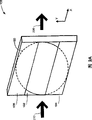
Figure 1A-1C is the pattern of polarization device view according to the embodiment of the invention.Figure 1A is the top view of pattern of polarization device.Figure 1B is first side view along the pattern of polarization device of Fig. 1 cathetus BB.Fig. 1 C is second side view along the pattern of polarization device of Fig. 1 cathetus CC.
Fig. 2 A utilizes the pattern of polarization device along three polarization districts that produce on the incident beam xsect according to the embodiment of the invention.
Fig. 2 B is the mixed polarized pattern in three districts that utilizes horizontal polarization incident light irradiation pattern of polarization device to produce according to the embodiment of the invention.
Fig. 2 C is the mixed polarized pattern in three districts that utilizes vertical polarization incident light irradiation pattern of polarization device to produce according to the embodiment of the invention.
Fig. 2 D is the view according to embodiment of the invention explanation light-beam shaper and the combination of pattern of polarization device.
Fig. 3 A, 3B, 4A, 4B, 5A, 5B, 6A and 6B are the various pattern of polarization that can produce according to the embodiment of the invention.
Fig. 7 is the polarized illumination device that comprises the pattern of polarization device according to the embodiment of the invention in etching system.
Embodiment
Referring now to the various elements of the present invention who provides with figure notation, discussion of the invention can make the professional make and use the present invention.
Figure 1A-1C is the view according to the pattern of polarization device 100 of the embodiment of the invention.Shown in Figure 1A, pattern of polarization device 100 comprises framework 110, and it clamps the polarized glass sheet 102 of framework 110 centers.Framework 110 can also be clamped in the ground floor two the unpolarized glass sheet 104 and 106 on the polarized glass sheet 102 relative both sides.Shown in Figure 1B and 1C, framework 110 can also clamp polarized glass sheet 102 ' the second layer, polarized glass sheet 102 ' be unpolarized glass sheet 104 in the rhythmo structure below each glass sheet 102-106 of ground floor ' and 106 ' between.
Polarized glass sheet 102,102 ' can rotate light incides the polarization direction on the glass sheet.For example, polarized glass sheet 102,102 ' can make by birefringent material, for example, quartz or magnesium fluoride (MgF
2).In an example, glass sheet 102 and 102 ' crossing a plurality of optical axises are arranged, and be polished to clean 1/2 wavelength of incident beam.In this manner, glass sheet 102 and 102 ' effect be half-wave plate, be used to rotate polarization direction 90 degree of incident ray polarized light.Two multistage wave plate laminations of glass sheet 102 and 102 ' can be to be forming accurate zero-th order waveplates, thereby reduce its heat sensitivity.
Unpolarized glass sheet 104,104 ' and 106,106 ' transmitted light by and do not change the polarization direction greatly.In an example, unpolarized glass sheet 104,104 ' and 106,106 ' can make by non-birefringent material, for example, vitreosil or calcium fluoride (CaF
2).In this manner, it is poor that glass sheet 104,104 ' and 106,106 ' help reduce to propagate between the light by pattern of polarization device 100 unnecessary optical path length.Unpolarized glass sheet 104,104 ' and 106,106 ' choose wantonly, if desired, can omit these unpolarized glass sheet.
Shown in Figure 1B, framework 110 can comprise dividing plate 115, it by gap 120 glass sheet 102-106 and glass sheet 102 '-106 ' separate.On the both sides of the edge of each glass sheet 102-106 and 102 '-106 ', can also dispose holder 118, therefore, can add external force (clamping, bonding etc.) and clamp glass sheet 102-106 and 102 '-106 ', it is positioned in the framework 110.The advantage of dividing plate 115 is, can produce and/or adjusting play 120 adapting to glass sheet 102-106,102 '-106 ' in the thermal expansivity of used different materials.Dividing plate 115 and holder 118 be choose wantonly and as illustration, rather than limitation of the present invention.Can utilize the dividing plate and/or the holder of other types, this is conspicuous for the professional.
In general, according to required form factor or other design criteria, framework 110 can have shape and area arbitrarily, is suitable for clamping glass sheet 102-106 and 102 '-106 '.In one embodiment, glass sheet 102-106 and 102 '-106 ' is that rectangle (or square) and framework 110 also are rectangle (or squares), and its area enough can be clamped glass sheet 102-106 and 102 '-106 ' greatly, shown in Figure 1A-1C.The present invention is this shape of limitation not, and glass sheet 102-106 and 102 '-106 ' and framework 110 can have other shape, and this is conspicuous for the professional.
Pattern of polarization device 100 can be inserted on the light path of optical system, and it includes but not limited to that the luminaire of pupil plane is arranged.Figure 1A represents that also it drops in the pupil of optical system (not shown) corresponding to the imaging area 150 in pattern of polarization device 100 zones.In the example of Figure 1A, imaging area 150 has three zones, and they are corresponding to the zone separately of glass sheet 102-106 and 102 '-106 '.Because polarized glass sheet 102 and 102 ' have be different from unpolarized glass sheet 104,106 and 104 ', 106 ' polarization properties, thereby on the pupil of optical system, present pattern of polarization.
Following pattern of polarization device 100 operations of describing generation specific polarization pattern with reference to Fig. 2-6.Can produce the mixed polarized pattern in three districts.In Fig. 2 A, incident beam 210 transmission are by pattern of polarization device 100, and it exports an output beam 220.Incident beam 210 can be the linearly polarized light along x axle (also being referred to as horizontal direction).Fig. 2 B represents the mixed polarized pattern 230 in three districts that pattern of polarization device 100 produces, and it is the result who utilizes 210 irradiations of along continuous straight runs linear polarization incident beam.Pattern of polarization 230 comprises the center 232 between two external zoness 234 and 236.The light of center 232 in transmission by polarized glass sheet 102,102 ' become afterwards orthogonal polarized light.The light of external zones 234 in transmission by polarized glass sheet 104,104 ' still keep afterwards horizontal polarization light.The light of external zones 236 in transmission by polarized glass sheet 106,106 ' still keep afterwards horizontal polarization light.
Perhaps, incident beam 210 can be the linearly polarized light along y axle (also being referred to as vertical direction).Fig. 2 C represents the mixed polarized pattern 240 in three districts that pattern of polarization device 100 produces, and it is to utilize the vertically result of linear polarization incident beam 210 irradiations.Pattern of polarization 240 comprises the center 242 between two external zoness 244 and 246.The light of center 242 in transmission by polarized glass sheet 102,102 ' become afterwards horizontal polarization light.The light of external zones 244 in transmission by polarized glass sheet 104,104 ' still keep afterwards orthogonal polarized light.The light of external zones 246 in transmission by polarized glass sheet 106,106 ' still keep afterwards orthogonal polarized light.
In this manner, the advantage of pattern of polarization device 100 is by input level or orthogonal polarized light, can obtain different pattern of polarization.This can utilize the whole bag of tricks to realize, it includes but not limited to: provide a linear polarizer at the light source place and along with respect to the level of pattern of polarization device 100 or vertical direction is rotated this polarizer and/or with respect to linear polarization light source rotatory polarization pattern means 100.
According to another feature, can also provide the light-beam shaper that makes up with the pattern of polarization device to produce other pattern.Fig. 2 D is light-beam shaper 250 views according to the embodiment of the invention and 100 combinations of pattern of polarization device.Light-beam shaper 250 can be diffraction optical element or mask, and its shaping incident beam 210 and the light beam that transmits shaping be to pattern of polarization device 100, output beam 260 of pattern of polarization device 100 outputs.Perhaps, light-beam shaper 250 can be configured in the opposite side of pattern of polarization device 100, is used to receive the light of transmission by pattern of polarization device 100.Fig. 3 A, 3B, 4A, 4B, 5A, 5B, 6A and 6B represent that the light-beam shaper 250 according to embodiment of the invention utilization and 100 combinations of pattern of polarization device produces other pattern of polarization.
Can produce low σ (Iow sigma) linearity pattern (Fig. 3 A and 3B).The linear vertical polarization pattern of the low σ 300A that Fig. 3 A represents to utilize pattern of polarization device 100 to produce, this be the incident beam 210 irradiation glass sheet 102,102 that utilize the along continuous straight runs linear polarization ' the result.Pattern of polarization 300A comprises the center 310A that concentric circles external zones 320A surrounds.The light of center 310A in transmission by polarized glass sheet 102,102 ' become afterwards orthogonal polarized light.Because light does not appear in light-beam shaper 250 in external zones 320A.Light-beam shaper 250 can be the mask that concentric circles is arranged, the light among its congested areas 320A.Perhaps, light-beam shaper 250 can be the optical element of diffraction optical element or other types, it only guide incoming light to the glass sheet 102,102 that reaches among the regional 310A '.If incident beam is enough narrow, it only incide glass sheet 102,102 ', then can omit light-beam shaper 250.
Similarly, the low σ level of linearity pattern of polarization 300B that Fig. 3 B represents to utilize pattern of polarization device 100 to produce, this be utilize the incident beam 210 irradiation glass sheet 102,102 of linear polarization vertically ' the result.Pattern of polarization 300B comprises the center 310B that concentric circles external zones 320B surrounds.The light of center 310B in transmission by polarized glass sheet 102,102 ' become afterwards horizontal polarization light.Because light-beam shaper 250, perhaps, the size of light beam is a situation about describing among above Fig. 3, does not occur light in external zones 320B.
In this manner, the advantage of pattern of polarization device 100 is by input level or orthogonal polarized light, can obtain low σ linear polarization pattern (level or vertical).
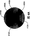
Can produce tangential and four utmost point patterns (Fig. 4 A and 4B) radially.Fig. 4 A represents to utilize tangential four utmost point pattern of polarization 400A of pattern of polarization device 100 and light-beam shaper 250 generations, and this is the result who utilizes 210 irradiations of along continuous straight runs linear polarization incident beam.Pattern 400A comprises 4 polar region 410A that tangential polarization light is arranged, 412A, 414A, and 416A.Utilize light-beam shaper 250 can be near the pupil external zones formation polar region 410A, 412A, 414A, and 416A.Polar region 414A, the light among the 416A in transmission by polarized glass sheet 102,102 ' become afterwards orthogonal polarized light.Light among the polar region 410A in transmission by polarized glass sheet 106,106 ' still remain afterwards horizontal polarization light.Light among the polar region 412A in transmission by polarized glass sheet 104,104 ' still remain afterwards horizontal polarization light.Light does not appear in spoke shape district 420A.Light-beam shaper 250 can be the mask that the spoke shape is arranged, the light among its congested areas 420A.Perhaps, light-beam shaper 250 can be the optical element of diffraction optical element or other types, and it only guides incoming light to and reaches corresponding to polar region 410A, 412A, pattern of polarization device 100 zones of 414A and 416A.
Fig. 4 B represents to utilize radially four utmost point pattern 400B of pattern of polarization device 100 and light-beam shaper 250 generations, and this is to utilize the vertically result of linear polarization incident beam 210 irradiations.Pattern 400B comprises 4 polar region 410B that radial polarisation light is arranged, 412B, 414B, and 416B.Utilize light-beam shaper 250 can be near the pupil external zones formation polar region 410B, 412B, 414B, and 416B.Polar region 414B, the light among the 416B in transmission by polarized glass sheet 102,102 ' become afterwards horizontal polarization light.Light among the polar region 410B in transmission by polarized glass sheet 106,106 ' still remain afterwards orthogonal polarized light.Light among the polar region 412B in transmission by polarized glass sheet 104,104 ' still remain afterwards orthogonal polarized light.Light does not appear in spoke shape district 420B.Light-beam shaper 250 can be the mask that the spoke shape is arranged, the light among its congested areas 420B.Perhaps, light-beam shaper 250 can be the optical element of diffraction optical element or other types, and it only guides incoming light to and reaches corresponding to polar region 410B, 412B, pattern of polarization device 100 zones of 414B and 416B.
In this manner, be, can obtain tangential and four utmost point patterns radially by input level or orthogonal polarized light with the advantage of the pattern of polarization device 100 of light-beam shaper 250 combination.
Can produce radially dipole pattern (Fig. 5 A and 5B).Fig. 5 A represents to utilize the radially dipole pattern of polarization 500A of pattern of polarization device 100 and light-beam shaper 250 generations, and this is to utilize the vertically result of linear polarization incident beam 210 irradiations.Pattern 500A includes two polar region 510A of radial polarisation light, 512A.Utilize light-beam shaper 250 can near the top of pupil external zones and bottom, form polar region 510A, 512A.Light among the polar region 510A in transmission by polarized glass sheet 106,106 ' still remain afterwards orthogonal polarized light.Light among the polar region 512A in transmission by polarized glass sheet 104,104 ' still remain afterwards orthogonal polarized light.Light does not appear in the 520A of butterfly collar interface.Light-beam shaper 250 can be the mask that the bow tie shape is arranged, the light among its congested areas 520A.Perhaps, light-beam shaper 250 can be the optical element of diffraction optical element or other types, and it only guides incoming light to and reaches corresponding to polar region 510A, pattern of polarization device 100 zones of 512A.
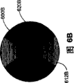
Fig. 5 B represents to utilize the radially dipole pattern of polarization 500B of pattern of polarization device 100 and light-beam shaper 250 generations, and this is to utilize the vertically result of linear polarization incident beam 210 irradiations.Pattern 500B includes two polar region 510B of radial polarisation light, 512B.Utilize light-beam shaper 250 can near the left side of pupil external zones and right side, form polar region 510B, 512B.Polar region 510B, the light among the 512B in transmission by polarized glass sheet 102,102 ' remain afterwards orthogonal polarized light.Light does not appear in the 520B of butterfly collar interface.Light-beam shaper 250 can be the mask that the bow tie shape is arranged, the light among its congested areas 520B.Perhaps, light-beam shaper 250 can be the optical element of diffraction optical element or other types, and it only guides incoming light to and reaches corresponding to polar region 510B, pattern of polarization device 100 zones of 512B.
In this manner, be by the input orthogonal polarized light and utilize light-beam shaper 250 direct light to arrive top and bottom zone or left side and right side region, can obtain radially dipole pattern with the advantage of the pattern of polarization device 100 of light-beam shaper 250 combination.For example, when light-beam shaper 250 is the mask of bow tie shape, only need this mask of rotation can congested areas 520A or 520B in light.
Can produce tangential dipole pattern (Fig. 6 A and 6B).Fig. 6 A represents to utilize the tangential dipole pattern of polarization 600A of pattern of polarization device 100 and light-beam shaper 250 generations, and this is the result who utilizes 210 irradiations of along continuous straight runs linear polarization incident beam.Pattern 600A includes two polar region 610A of tangential polarization light, 612A.Utilize light-beam shaper 250 to form polar region 610A, 612A in the left and right sides of pupil external zones.Polar region 610A, the light among the 612A in transmission by polarized glass sheet 102,102 ' be orthogonal polarized light afterwards.Light does not appear in the 620A of butterfly collar interface.Light-beam shaper 250 can be the mask that the bow tie shape is arranged, the light among its congested areas 620A.Perhaps, light-beam shaper 250 can be the optical element of diffraction optical element or other types, and it only guides incoming light to and reaches corresponding to polar region 610A, pattern of polarization device 100 zones of 612A.
Fig. 6 B represents to utilize the tangential dipole pattern of polarization 600B of pattern of polarization device 100 and light-beam shaper 250 generations, and this is the result who utilizes 210 irradiations of along continuous straight runs linear polarization incident beam.Pattern 600B includes two polar region 610B of tangential polarization light, 612B.Utilize light-beam shaper 250 to form polar region 610B, 612B in the top and the bottom of pupil external zones.Light among the polar region 610B in transmission by polarized glass sheet 106,106 ' still keep afterwards horizontal polarization light.Light among the polar region 612B in transmission by polarized glass sheet 104,104 ' still keep afterwards horizontal polarization light.Light does not appear in the 620B of butterfly collar interface.Light-beam shaper 250 can be the mask that the bow tie shape is arranged, the light among its congested areas 620B.Perhaps, light-beam shaper 250 can be the optical element of diffraction optical element or other types, and it only guides incoming light to and reaches corresponding to polar region 610B, pattern of polarization device 100 zones of 612B.
In this manner, be by the input level polarized light and utilize light-beam shaper 250 direct light to arrive top and bottom zone or left side and right side region, can obtain tangential dipole pattern with the advantage of the pattern of polarization device 100 of light-beam shaper 250 combination.For example, when light-beam shaper 250 is the mask of bow tie shape, only need this mask of rotation just can congested areas 620A or 620B in light.
Fig. 7 is polarized illumination device 700 views that comprise pattern of polarization device 100 and/or light-beam shaper 750 according to the embodiment of the invention in etching system.Light-beam shaper 750 and pattern of polarization device 100 are to arrange along the common light path of luminaire 700.Light-beam shaper 750 can comprise the first light-beam shaper element 750A and the second light-beam shaper element 750B, and they are arranged on the relative both sides of pattern of polarization device 100, as shown in Figure 7.In an example, the first light-beam shaper element 750A (for example comprises one or more diffraction optical elements, diffraction grating), its optical diffraction from light source 702 (for example, ultraviolet laser) becomes two or four diffracted beams corresponding to polar region around luminaire 700 pupils.Other optical lens or element can also be set, and for example, one or more collimation lenses are used to fill the pupil and/or the visual field of luminaire 700, and this is well-known in the design luminaire.The second light-beam shaper element 750B can comprise mask, is used for further blocking the pattern of polarization at unnecessary light and cleaning pupil place.
The output beam 705 of polarized illumination device 700 output polarization optical illumination is to mask 710.Transmission is to be projected on the wafer 730 by optical system 720 (that is projection optics system) by the light 715 of mask (or from mask reflection) during printing.The etching system of this use polarized illumination device 700 is as illustration, is not limitation of the present invention.Polarized illumination device 700 can be used in the etching system or instrument of any kind, and this is conspicuous for the professional.
According to another feature of the present invention, output beam 705 can have various arbitrarily pattern of polarization on luminaire 700 pupils, these patterns include but not limited to, the mixed polarized pattern in three districts, low σ linearity pattern, radially dipole pattern, tangentially dipole pattern, tangential four utmost point patterns and four utmost point patterns radially.Relevant with the configuration of light-beam shaper 750 and pattern of polarization device 100, polarized illumination device 700 can provide any pattern in these patterns shown in above-mentioned Fig. 2 B-6B.In addition, can exchange polarized illumination device 700 so that these any patterns to be provided, it depends on the configuration of light-beam shaper 750 and pattern of polarization device 100, as above-mentioned Fig. 2 B-6B.That for example, can utilize that the controller (not shown) changes light-beam shaper 750 and pattern of polarization device 100 is configured to obtain required pattern.In this manner, during printing, can automatically change pattern, thereby make pupil that different pattern of polarization be arranged during wafer exposure.For example, the one or more diffraction grating turnover light paths of controller in can mobile beam former element 750A, thereby two or four diffracted beams of (dipole or four utmost point patterns) generation are (+1 grade in the polar region,-1 grade or higher diffracted beam level time), and/or only transmission produces rudimentary light beam of low σ linearity pattern.Similarly, can be around the optical axis rotatory polarization pattern means 100 of light path, the linearly polarized light that makes input is along continuous straight runs or vertical direction, it depends on required pattern of polarization.At last, the one or more masks turnover in can also mobile beam former element 750B by luminaire 700 light path and rotate mask, therefore, according to required pattern of polarization, produce the mask shape (for example, concentric circles, spoke or bow tie shape) of required orientation.
In some photolithography was used, pattern of polarization shown in Figure 3 may be favourable for polarized illumination device 700.For example, this polarization mode is used in the double exposure of utilizing alternating phase-shift mask.Specifically, the phase shifting mask that replaces by different way diffraction from the light of binary mask.Under the situation of alternating phase-shift mask, the axial pencil of luminaire is diffracted into projection optics system (" PO ") symmetrically.Utilize thin illuminating bundle on the axle to obtain minimum and feature the most clearly.Yet in order once to realize the light beam of several orientation characteristics, a light beam can be used for having the mask of vertical orientated structure.Then, utilize second light beam and second mask of the horizontal structure wafer that exposes is once more arranged.
So the pattern of polarization among Fig. 3 can be used in the double exposure of utilizing alternating phase-shift mask.For example, mainly be the mask of perpendicular line, that is, these straight lines are straight lines vertical and that along continuous straight runs repeats, main along continuous straight runs diffraction on the PO pupil.If the polarization direction is vertical, then these light beams more effectively reconfigure on wafer.Similarly, utilize the horizontal polarization light beam better imaging mainly be second mask of horizontal structure.Can expose these two masks to identical wafer, but not between the two " developed film ", and the double exposure image that forms is better than the image that utilizes non-polarized light beam single exposure total to obtain.
In another embodiment, in using, photolithography may need pattern of polarization shown in Figure 4.For example, utilize binary mask, the vertical polarization polar region shown in Fig. 4 A on luminaire pupil right side and the left side edge is the very little perpendicular line of imaging better.Other the two poles of the earth+1 grade and-1 order diffraction light beam be diffracted into outside the pO pupil and it does not arrived on the wafer.Similarly, utilize binary mask, the horizontal polarization of luminaire pupil top and bottom shown in Fig. 4 B is the very little horizontal line of imaging extremely better.In general, the contrast that produces owing to tangential polarization strengthens above the contrast decline that causes owing to non-imaging polar region.In this manner, can print all features in single exposure, if there is not the control of polarization direction, this is impossible realize.
In another embodiment, utilize binary mask, the pattern of polarization that provides among Fig. 5 and 6 can be used on mainly to be level and mainly to be in the double exposure of vertical stratification.Under the situation of alternating phase-shift mask, choosing double exposure is in order to realize the advantage of light beam.For given structural approach, often adopt double exposure, four extremely in only polarity can produce image.Other the two poles of the earth do not produce image.+ 1 grade is outside the PO pupil with-1 order diffraction light beam.Only the Zero-order diffractive light beam arrives wafer, and it does not produce image, but influence is to the contrast of constant background.
The invention is not restricted to produce the lithography system that has optical system shown in above-mentioned pattern of polarization or the accompanying drawing in the pattern of polarization.On the contrary, for any given graticule or mask, the best pupil that can be useful on printing is filled and the optimal polarization light beam.So the present invention comprises the pattern of polarization of this best.
Used polarized glass sheet can utilize the optical quality material of the required wavelength of transmission in the optical system of the present invention.Therefore, the invention is not restricted to use the light of any specific wavelength.Typical wavelength is infrared, ultraviolet (" UV "), and visible light.In typical photolithography is used, can use the polarized glass sheet of UV irradiation, it can be by quartz, and the other materials or the combination of materials of magnesium fluoride or transillumination light beam are made.
Though above we have described various embodiment of the present invention, should be understood that they only are as illustration, rather than limitation of the present invention.Therefore, breadth and depth of the present invention should not be subjected to the restriction of above-mentioned exemplary embodiments, and scope of the present invention is to be subjected to following claims and the quite restriction of content thereof.
Claims (12)
1. the pattern of polarization device on the luminaire that is used in pupil comprises:
(a) framework;
(b) at least one polaroid, be coupled to described framework, each polaroid changes the polarisation of light direction that transmission is passed through, and wherein said at least one polaroid comprises first polaroid and second polaroid of being made by birefringent material, and they are arranged in the lamination separately the ground floor and the second layer; With
(c) the first couple who is made by non-birefringent material is unpolarized and second pair unpolarized, described first pair unpolarized is ground floor on being positioned at the both sides vis-a-vis of described first polaroid, and described second pair unpolarized be the second layer on being positioned at the both sides vis-a-vis of described second polaroid
Thereby on the luminaire pupil, obtain at least one pattern of polarization.
2. according to the pattern of polarization device of claim 1, wherein said first and second polaroids rotation polarisation of light direction about 90 is spent.
3. according to the pattern of polarization device of claim 1, wherein said framework also comprises the dividing plate that a gap is provided, this gap described in the ground floor with the second layer in described separate.
4. according to the pattern of polarization device of claim 1, wherein said first and second polaroids are connected to the described framework of center, the center is between first external zones and second external zones in described framework, and about 90 degree of polarisation of light direction that wherein said first and second polaroids rotation transmission is passed through, therefore, on the luminaire pupil, obtain pattern of polarization, and this pattern of polarization is the pattern that is selected from next group: the mixed polarized pattern in three districts, low σ linearity pattern, dipole pattern radially, tangential dipole pattern, tangential four utmost point patterns and four utmost point patterns radially.
5. equipment that is used for providing at least one pattern of polarization on the pupil of the luminaire of etching system comprises:
(a) light-beam shaper; With
(b) pattern of polarization device, by the light path arrangement along luminaire, described pattern of polarization device comprises:
Framework;
At least one polaroid, wherein said at least one polaroid comprise first polaroid and second polaroid of being made by birefringent material, and they are arranged in the lamination separately the ground floor and the second layer; With
Unpolarized and second couple unpolarized of the first couple who makes by non-birefringent material, described first pair unpolarized is ground floor on being positioned at the both sides vis-a-vis of described first polaroid, and described second pair unpolarized be the second layer on being positioned at the both sides vis-a-vis of described second polaroid
Wherein said framework comprises the center, and the center is between first external zones and second external zones in described framework, and the supporting that described at least one polaroid is the above framework of acceptor center district.
6. according to the equipment of claim 5, wherein said light-beam shaper comprises in diffraction optical element and the mask at least.
7. according to the equipment of claim 5, wherein said light-beam shaper is divided into a plurality of light beams that separate to the linearly polarized light beam of input, and these light beams shine on the pattern of polarization device zone relevant with the pupil polar region.
8. according to the equipment of claim 7, wherein a plurality of light beams that separate comprise two light beams, these light beam irradiates make the pattern of polarization that provides on pupil comprise radially dipole pattern or tangential dipole pattern to the pattern of polarization device zone relevant with the pupil dipole zone.
9. according to the equipment of claim 7, wherein a plurality of light beams that separate comprise four light beams, these light beam irradiates make the pattern of polarization that provides on pupil comprise radially four utmost point patterns or tangential four utmost point patterns to the pattern of polarization device zone relevant with pupil four polar regions.
10. according to the equipment of claim 7, the linearly polarized light beam of wherein said light-beam shaper restriction input makes the pattern of polarization that provides on pupil comprise low σ linear polarization pattern to the polaroid of pupil center.
11. according to the equipment of claim 7, the linearly polarized light beam of importing on center and the external zones in the wherein said light-beam shaper transport frame makes the pattern of polarization that provides on pupil comprise the mixed polarized pattern in three districts.
12., wherein can move described light-beam shaper and pattern of polarization device to produce dissimilar pattern of polarization according to the equipment of claim 7.
Applications Claiming Priority (2)
| Application Number | Priority Date | Filing Date | Title |
|---|---|---|---|
| US10/852,099 US7324280B2 (en) | 2004-05-25 | 2004-05-25 | Apparatus for providing a pattern of polarization |
| US10/852,099 | 2004-05-25 |
Publications (2)
| Publication Number | Publication Date |
|---|---|
| CN1702492A CN1702492A (en) | 2005-11-30 |
| CN100487520C true CN100487520C (en) | 2009-05-13 |
Family
ID=34936768
Family Applications (1)
| Application Number | Title | Priority Date | Filing Date |
|---|---|---|---|
| CNB2005100729883A Expired - Fee Related CN100487520C (en) | 2004-05-25 | 2005-05-25 | Apparatus for providing a pattern of polarization |
Country Status (9)
| Country | Link |
|---|---|
| US (3) | US7324280B2 (en) |
| EP (2) | EP1749241A1 (en) |
| JP (2) | JP4361513B2 (en) |
| KR (1) | KR100665138B1 (en) |
| CN (1) | CN100487520C (en) |
| DE (1) | DE602005008666D1 (en) |
| SG (1) | SG117600A1 (en) |
| TW (1) | TWI280460B (en) |
| WO (1) | WO2005116772A1 (en) |
Families Citing this family (41)
| Publication number | Priority date | Publication date | Assignee | Title |
|---|---|---|---|---|
| JP4735258B2 (en) | 2003-04-09 | 2011-07-27 | 株式会社ニコン | Exposure method and apparatus, and device manufacturing method |
| TWI474132B (en) | 2003-10-28 | 2015-02-21 | 尼康股份有限公司 | Optical illumination device, projection exposure device, exposure method and device manufacturing method |
| TWI612338B (en) | 2003-11-20 | 2018-01-21 | 尼康股份有限公司 | Optical illuminating apparatus, exposure device, exposure method, and device manufacturing method |
| US20070019179A1 (en) | 2004-01-16 | 2007-01-25 | Damian Fiolka | Polarization-modulating optical element |
| US8270077B2 (en) | 2004-01-16 | 2012-09-18 | Carl Zeiss Smt Gmbh | Polarization-modulating optical element |
| CN101793993B (en) | 2004-01-16 | 2013-04-03 | 卡尔蔡司Smt有限责任公司 | Optical elements, optical arrangement and system |
| TWI395068B (en) | 2004-01-27 | 2013-05-01 | 尼康股份有限公司 | Optical system, exposure device and method of exposure |
| TWI360837B (en) * | 2004-02-06 | 2012-03-21 | Nikon Corp | Polarization changing device, optical illumination |
| US7324280B2 (en) * | 2004-05-25 | 2008-01-29 | Asml Holding N.V. | Apparatus for providing a pattern of polarization |
| US7548370B2 (en) * | 2004-06-29 | 2009-06-16 | Asml Holding N.V. | Layered structure for a tile wave plate assembly |
| KR100614651B1 (en) * | 2004-10-11 | 2006-08-22 | 삼성전자주식회사 | Apparatus And Method For Pattern Exposure, Photomask Used Therefor, Design Method For The Photomask, Illuminating System Therefor and Implementing Method For The Illuminating System |
| US7312852B2 (en) * | 2004-12-28 | 2007-12-25 | Asml Netherlands B.V. | Polarized radiation in lithographic apparatus and device manufacturing method |
| US7345740B2 (en) * | 2004-12-28 | 2008-03-18 | Asml Netherlands B.V. | Polarized radiation in lithographic apparatus and device manufacturing method |
| KR20080066041A (en) * | 2005-11-10 | 2008-07-15 | 가부시키가이샤 니콘 | Lighting optical system, exposure system, and exposure method |
| US7525642B2 (en) * | 2006-02-23 | 2009-04-28 | Asml Netherlands B.V. | Lithographic apparatus and device manufacturing method |
| EP1857879A1 (en) * | 2006-05-15 | 2007-11-21 | Advanced Mask Technology Center GmbH & Co. KG | An illumination system and a photolithography apparatus |
| DE102006032810A1 (en) | 2006-07-14 | 2008-01-17 | Carl Zeiss Smt Ag | Illumination optics for a microlithography projection exposure apparatus, illumination system with such an illumination optics, microlithography projection exposure apparatus with such an illumination system, microlithographic production method for components and component produced by this method |
| DE102006032878A1 (en) * | 2006-07-15 | 2008-01-17 | Carl Zeiss Smt Ag | Illumination system of a microlithographic projection exposure apparatus |
| DE102006038643B4 (en) | 2006-08-17 | 2009-06-10 | Carl Zeiss Smt Ag | Microlithographic projection exposure apparatus and microlithographic exposure method |
| US8035803B2 (en) * | 2006-09-06 | 2011-10-11 | Carl Zeiss Smt Gmbh | Subsystem of an illumination system of a microlithographic projection exposure apparatus |
| KR20080073196A (en) * | 2007-02-05 | 2008-08-08 | 엘지전자 주식회사 | Method for efficiently transmitting channel quality information in mimo system |
| DE102008013567A1 (en) | 2007-05-08 | 2008-11-13 | Carl Zeiss Smt Ag | Lighting device for microlithographic projection exposure system, has optical element adjusting polarization conditions of radiations, where conditions are different from each other and radiations are deflected in different directions |
| US20080285000A1 (en) * | 2007-05-17 | 2008-11-20 | Asml Netherlands B.V. | Lithographic apparatus and device manufacturing method |
| JP4971932B2 (en) * | 2007-10-01 | 2012-07-11 | キヤノン株式会社 | Illumination optical system, exposure apparatus, device manufacturing method, and polarization control unit |
| DE102007055567A1 (en) | 2007-11-20 | 2009-05-28 | Carl Zeiss Smt Ag | Optical system |
| US8334976B2 (en) | 2008-03-18 | 2012-12-18 | The Board Of Trustees Of The University Of Illinois | Second-order nonlinear susceptibility of a nanoparticle using coherent confocal microscopy |
| US8045161B2 (en) * | 2008-03-18 | 2011-10-25 | The Board Of Trustees Of The University Of Illinois | Robust determination of the anisotropic polarizability of nanoparticles using coherent confocal microscopy |
| NL1036786A1 (en) * | 2008-05-08 | 2009-11-11 | Asml Netherlands Bv | Lithographic apparatus and method. |
| JP5319766B2 (en) * | 2008-06-20 | 2013-10-16 | カール・ツァイス・エスエムティー・ゲーエムベーハー | Optical system of microlithography projection exposure apparatus and microlithography exposure method |
| JP2010197352A (en) * | 2009-02-27 | 2010-09-09 | Hitachi High-Technologies Corp | Defect inspection method and defect inspecting apparatus |
| US8553204B2 (en) * | 2009-05-20 | 2013-10-08 | Nikon Corporation | Movable body apparatus, exposure apparatus, exposure method, and device manufacturing method |
| DE102011003035A1 (en) * | 2010-02-08 | 2011-08-11 | Carl Zeiss SMT GmbH, 73447 | Polarization-influencing optical arrangement, as well as optical system of a microlithographic projection exposure apparatus |
| EP2369413B1 (en) | 2010-03-22 | 2021-04-07 | ASML Netherlands BV | Illumination system and lithographic apparatus |
| JP2014059507A (en) * | 2012-09-19 | 2014-04-03 | Fuji Xerox Co Ltd | Image forming apparatus |
| US20140111849A1 (en) * | 2012-10-18 | 2014-04-24 | Polarization Solutions, Llc | Apparatus and method for mosaic gratings-based polarizer |
| WO2015021411A1 (en) | 2013-08-09 | 2015-02-12 | Kla-Tencor Corporation | Multi-spot illumination for improved detection sensitivity |
| US9519093B2 (en) | 2013-08-23 | 2016-12-13 | Kla-Tencor Corporation | Broadband and wide field angle compensator |
| GB2521443B (en) * | 2013-12-20 | 2016-06-29 | Vizeye Ltd | Apparatus and method for inducing polarization perception in an observer |
| JP6619619B2 (en) * | 2015-11-04 | 2019-12-11 | 日東電工株式会社 | Polarizer, polarizing plate, and method for producing polarizer |
| CN105785581B (en) * | 2016-05-09 | 2018-06-22 | 湖州中科光电技术有限公司 | A kind of design method for the micro structural component for being used to generate rotational symmetry polarised light |
| CN110160002B (en) * | 2018-02-12 | 2022-02-25 | 深圳市绎立锐光科技开发有限公司 | Lighting system |
Family Cites Families (147)
| Publication number | Priority date | Publication date | Assignee | Title |
|---|---|---|---|---|
| JPH06275493A (en) * | 1993-03-19 | 1994-09-30 | Fujitsu Ltd | Projection exposure |
| US5465220A (en) * | 1992-06-02 | 1995-11-07 | Fujitsu Limited | Optical exposure method |
| US2269713A (en) * | 1939-09-09 | 1942-01-13 | Ralph J Erwin | Shutter for projection apparatus |
| US2420252A (en) * | 1945-03-23 | 1947-05-06 | Polaroid Corp | Optical interference sight for guns, cameras, or the like |
| US2473857A (en) | 1946-12-05 | 1949-06-21 | Burchell Holloway Corp | Apparatus for insertion in color display devices utilizing polarized light for securing changing saturation of specific hues in fixed zones as vewed by observers |
| US3049051A (en) * | 1956-01-28 | 1962-08-14 | Debrie Andre Victor Le Clement | Arrangement with polarizing grating for the photographic establishment of filters with black and white networks |
| GB856621A (en) | 1956-07-20 | 1960-12-21 | Nat Res Dev | Improvements in or relating to polarising microscopes |
| US3484714A (en) | 1964-12-16 | 1969-12-16 | American Optical Corp | Laser having a 90 polarization rotator between two rods to compensate for the effects of thermal gradients |
| US3438692A (en) | 1965-03-08 | 1969-04-15 | Bell Telephone Labor Inc | Birefringent device for forming multiple images |
| US3630598A (en) | 1970-01-02 | 1971-12-28 | Xerox Corp | Optical demodulation filter |
| US3719415A (en) | 1971-09-22 | 1973-03-06 | Bell Telephone Labor Inc | Radial and tangential polarizers |
| US3892470A (en) | 1974-02-01 | 1975-07-01 | Hughes Aircraft Co | Optical device for transforming monochromatic linearly polarized light to ring polarized light |
| FR2385241A1 (en) | 1976-12-23 | 1978-10-20 | Marie G R P | POLARIZATION MODE CONVERTERS FOR LASER BEAMS AND PLASMA GENERATORS USING THEM |
| US4272158A (en) | 1979-03-02 | 1981-06-09 | Coherent, Inc. | Broadband optical diode for a ring laser |
| US4286843A (en) | 1979-05-14 | 1981-09-01 | Reytblatt Zinovy V | Polariscope and filter therefor |
| CA1253726A (en) | 1982-06-28 | 1989-05-09 | Masataka Shirasaki | Polarization rotation compensator and optical isolator using the same |
| DE3523641C1 (en) | 1985-07-02 | 1986-12-18 | Max-Planck-Gesellschaft zur Förderung der Wissenschaften e.V., 3400 Göttingen | Device for selecting rotationally symmetrical polarization components of a light bundle and use of such a device |
| US4744615A (en) | 1986-01-29 | 1988-05-17 | International Business Machines Corporation | Laser beam homogenizer |
| JP2995820B2 (en) | 1990-08-21 | 1999-12-27 | 株式会社ニコン | Exposure method and method, and device manufacturing method |
| US7656504B1 (en) | 1990-08-21 | 2010-02-02 | Nikon Corporation | Projection exposure apparatus with luminous flux distribution |
| US6252647B1 (en) | 1990-11-15 | 2001-06-26 | Nikon Corporation | Projection exposure apparatus |
| US5541026A (en) | 1991-06-13 | 1996-07-30 | Nikon Corporation | Exposure apparatus and photo mask |
| KR950004968B1 (en) | 1991-10-15 | 1995-05-16 | 가부시키가이샤 도시바 | Projection exposure apparatus |
| JP2866243B2 (en) | 1992-02-10 | 1999-03-08 | 三菱電機株式会社 | Projection exposure apparatus and method of manufacturing semiconductor device |
| JP2796005B2 (en) | 1992-02-10 | 1998-09-10 | 三菱電機株式会社 | Projection exposure apparatus and polarizer |
| JP3278896B2 (en) | 1992-03-31 | 2002-04-30 | キヤノン株式会社 | Illumination apparatus and projection exposure apparatus using the same |
| JP3246615B2 (en) * | 1992-07-27 | 2002-01-15 | 株式会社ニコン | Illumination optical device, exposure apparatus, and exposure method |
| US6404482B1 (en) * | 1992-10-01 | 2002-06-11 | Nikon Corporation | Projection exposure method and apparatus |
| JP2884947B2 (en) * | 1992-10-01 | 1999-04-19 | 株式会社ニコン | Projection exposure apparatus, exposure method, and method of manufacturing semiconductor integrated circuit |
| JPH06118623A (en) * | 1992-10-07 | 1994-04-28 | Fujitsu Ltd | Reticle and semiconductor aligner using the same |
| US5459000A (en) | 1992-10-14 | 1995-10-17 | Canon Kabushiki Kaisha | Image projection method and device manufacturing method using the image projection method |
| JPH06169415A (en) | 1992-11-30 | 1994-06-14 | Olympus Optical Co Ltd | Image pickup device |
| JP2866267B2 (en) | 1992-12-11 | 1999-03-08 | 三菱電機株式会社 | Optical drawing apparatus and optical drawing method for wafer substrate |
| JP2698521B2 (en) | 1992-12-14 | 1998-01-19 | キヤノン株式会社 | Catadioptric optical system and projection exposure apparatus having the optical system |
| US5739898A (en) | 1993-02-03 | 1998-04-14 | Nikon Corporation | Exposure method and apparatus |
| JP3099933B2 (en) * | 1993-12-28 | 2000-10-16 | 株式会社東芝 | Exposure method and exposure apparatus |
| KR0153796B1 (en) * | 1993-09-24 | 1998-11-16 | 사토 후미오 | Exposure apparatus and method |
| KR0166612B1 (en) * | 1993-10-29 | 1999-02-01 | 가나이 쓰토무 | Method and apparatus for exposing pattern, mask used therefor and semiconductor integrated circuit formed by using the same |
| JP3505810B2 (en) | 1993-10-29 | 2004-03-15 | 株式会社日立製作所 | Pattern exposure method and apparatus |
| US5442184A (en) * | 1993-12-10 | 1995-08-15 | Texas Instruments Incorporated | System and method for semiconductor processing using polarized radiant energy |
| DE19520563A1 (en) | 1995-06-06 | 1996-12-12 | Zeiss Carl Fa | Illumination device for a projection microlithography device |
| US6285443B1 (en) | 1993-12-13 | 2001-09-04 | Carl-Zeiss-Stiftung | Illuminating arrangement for a projection microlithographic apparatus |
| JPH07183201A (en) * | 1993-12-21 | 1995-07-21 | Nec Corp | Exposure device and method therefor |
| JP2836483B2 (en) | 1994-05-13 | 1998-12-14 | 日本電気株式会社 | Illumination optics |
| KR0173168B1 (en) * | 1994-02-24 | 1999-03-20 | 가네꼬 히사시 | Exposure system and illuminating apparatus used therein and method for exposing a resist film on a wafer |
| JPH088177A (en) | 1994-04-22 | 1996-01-12 | Canon Inc | Projection aligner and manufacture of device |
| US5663785A (en) | 1995-05-24 | 1997-09-02 | International Business Machines Corporation | Diffraction pupil filler modified illuminator for annular pupil fills |
| JP3534363B2 (en) | 1995-07-31 | 2004-06-07 | パイオニア株式会社 | Crystal lens and optical pickup optical system using the same |
| US5815247A (en) | 1995-09-21 | 1998-09-29 | Siemens Aktiengesellschaft | Avoidance of pattern shortening by using off axis illumination with dipole and polarizing apertures |
| DE19535392A1 (en) | 1995-09-23 | 1997-03-27 | Zeiss Carl Fa | Radial polarization-rotating optical arrangement and microlithography projection exposure system with it |
| DE19621512A1 (en) | 1996-05-29 | 1997-12-04 | Univ Schiller Jena | Polarisation establishment with respect to wavelength of source spectra |
| EP0823662A2 (en) | 1996-08-07 | 1998-02-11 | Nikon Corporation | Projection exposure apparatus |
| JPH1079337A (en) * | 1996-09-04 | 1998-03-24 | Nikon Corp | Projection aligner |
| US6111700A (en) | 1996-09-05 | 2000-08-29 | Fujitsu Limited | Optical display device having a reflection-type polarizer |
| US5841500A (en) | 1997-01-09 | 1998-11-24 | Tellium, Inc. | Wedge-shaped liquid crystal cell |
| US6055103A (en) * | 1997-06-28 | 2000-04-25 | Sharp Kabushiki Kaisha | Passive polarisation modulating optical element and method of making such an element |
| JP3264224B2 (en) | 1997-08-04 | 2002-03-11 | キヤノン株式会社 | Illumination apparatus and projection exposure apparatus using the same |
| DE19807120A1 (en) | 1998-02-20 | 1999-08-26 | Zeiss Carl Fa | Optical system with polarization compensator |
| US6327085B1 (en) | 1998-03-31 | 2001-12-04 | Nikon Corporation | Optical filter and optical device provided with this optical filter |
| DE69931690T2 (en) | 1998-04-08 | 2007-06-14 | Asml Netherlands B.V. | Lithographic apparatus |
| DE19829612A1 (en) | 1998-07-02 | 2000-01-05 | Zeiss Carl Fa | Microlithography lighting system with depolarizer |
| US6031658A (en) | 1998-09-25 | 2000-02-29 | University Of Central Florida | Digital control polarization based optical scanner |
| JP4065923B2 (en) | 1998-09-29 | 2008-03-26 | 株式会社ニコン | Illumination apparatus, projection exposure apparatus including the illumination apparatus, projection exposure method using the illumination apparatus, and adjustment method of the projection exposure apparatus |
| US6563567B1 (en) | 1998-12-17 | 2003-05-13 | Nikon Corporation | Method and apparatus for illuminating a surface using a projection imaging apparatus |
| ATE431619T1 (en) | 1999-01-06 | 2009-05-15 | Nikon Corp | METHOD FOR PRODUCING AN OPTICAL PROJECTION SYSTEM |
| JP2000347177A (en) * | 1999-03-29 | 2000-12-15 | Minolta Co Ltd | Display optical device and projector display device using the same |
| DE19921795A1 (en) * | 1999-05-11 | 2000-11-23 | Zeiss Carl Fa | Projection exposure system and exposure method of microlithography |
| US6721258B1 (en) | 1999-06-21 | 2004-04-13 | Citizen Watch Co., Ltd. | Optical device for super-resolution |
| KR100662319B1 (en) | 1999-07-05 | 2006-12-28 | 가부시키가이샤 니콘 | Method for producing quartz glass member and quartz glass member produced thereby |
| US6239853B1 (en) * | 1999-10-01 | 2001-05-29 | Rockwell Science Center, Llc | Staggered waveplate LCD privacy screen |
| US6361909B1 (en) | 1999-12-06 | 2002-03-26 | Industrial Technology Research Institute | Illumination aperture filter design using superposition |
| TWI282909B (en) | 1999-12-23 | 2007-06-21 | Asml Netherlands Bv | Lithographic apparatus and a method for manufacturing a device |
| DE10010131A1 (en) | 2000-03-03 | 2001-09-06 | Zeiss Carl | Microlithography projection exposure with tangential polarization involves using light with preferred direction of polarization oriented perpendicularly with respect to plane of incidence |
| JP3927753B2 (en) | 2000-03-31 | 2007-06-13 | キヤノン株式会社 | Exposure apparatus and device manufacturing method |
| US6553156B1 (en) | 2000-06-30 | 2003-04-22 | Oplink Communications, Inc. | Optical isolators with ultra-low polarization mode dispersion |
| JP3645801B2 (en) | 2000-08-24 | 2005-05-11 | ペンタックス株式会社 | Beam train detection method and phase filter for detection |
| JP2002075835A (en) | 2000-08-30 | 2002-03-15 | Nikon Corp | Illumination optical device and exposure system with the same |
| JP2002231619A (en) | 2000-11-29 | 2002-08-16 | Nikon Corp | Optical illumination equipment and aligner equipped with the same |
| TWI285295B (en) | 2001-02-23 | 2007-08-11 | Asml Netherlands Bv | Illumination optimization in lithography |
| US7375887B2 (en) | 2001-03-27 | 2008-05-20 | Moxtek, Inc. | Method and apparatus for correcting a visible light beam using a wire-grid polarizer |
| US20050018290A1 (en) * | 2001-04-05 | 2005-01-27 | Ferenc Kiss | Colour filter means having optical activity under the influence of a polarized light |
| WO2002088843A2 (en) | 2001-04-24 | 2002-11-07 | Canon Kabushiki Kaisha | Exposure method and apparatus |
| JP2002324743A (en) | 2001-04-24 | 2002-11-08 | Canon Inc | Exposing method and equipment thereof |
| US20020163629A1 (en) | 2001-05-07 | 2002-11-07 | Michael Switkes | Methods and apparatus employing an index matching medium |
| DE10124566A1 (en) | 2001-05-15 | 2002-11-21 | Zeiss Carl | Optical imaging system with polarizing agents and quartz crystal plate therefor |
| KR20040015251A (en) | 2001-05-15 | 2004-02-18 | 칼 짜이스 에스엠티 아게 | Objective with fluoride crystal lenses |
| DE10124474A1 (en) | 2001-05-19 | 2002-11-21 | Zeiss Carl | Microlithographic exposure involves compensating path difference by controlled variation of first and/or second optical paths; image plane difference is essentially independent of incident angle |
| DE10124803A1 (en) | 2001-05-22 | 2002-11-28 | Zeiss Carl | Polarizer and microlithography projection system with polarizer |
| US7053988B2 (en) | 2001-05-22 | 2006-05-30 | Carl Zeiss Smt Ag. | Optically polarizing retardation arrangement, and microlithography projection exposure machine |
| JP2002359176A (en) | 2001-05-31 | 2002-12-13 | Canon Inc | Luminaire, illumination control method, aligner, device and manufacturing method thereof |
| KR100576746B1 (en) | 2001-06-01 | 2006-05-03 | 에이에스엠엘 네델란즈 비.브이. | Lithographic apparatus, device manufacturing method, device manufactured thereby, control system, computer program, and computer program product |
| US6727992B2 (en) | 2001-07-06 | 2004-04-27 | Zygo Corporation | Method and apparatus to reduce effects of sheared wavefronts on interferometric phase measurements |
| US6788389B2 (en) | 2001-07-10 | 2004-09-07 | Nikon Corporation | Production method of projection optical system |
| US8354438B2 (en) | 2001-08-08 | 2013-01-15 | Michael Chez | Neurological functions |
| KR100431883B1 (en) | 2001-11-05 | 2004-05-17 | 삼성전자주식회사 | Projection Method and projection system |
| JP2003297727A (en) | 2002-04-03 | 2003-10-17 | Nikon Corp | Illumination optical device, exposure apparatus, and method of exposure |
| JP4324957B2 (en) | 2002-05-27 | 2009-09-02 | 株式会社ニコン | Illumination optical apparatus, exposure apparatus, and exposure method |
| CN1461974A (en) | 2002-05-31 | 2003-12-17 | Asml荷兰有限公司 | Assembling optical element external member and method, optical element, offset press, device manufacturing method |
| JP2004179172A (en) | 2002-06-26 | 2004-06-24 | Nikon Corp | Aligner, exposure method, and method of manufacturing device |
| US6965484B2 (en) | 2002-07-26 | 2005-11-15 | Massachusetts Institute Of Technology | Optical imaging systems and methods using polarized illumination and coordinated pupil filter |
| JP3958163B2 (en) | 2002-09-19 | 2007-08-15 | キヤノン株式会社 | Exposure method |
| TW200412617A (en) | 2002-12-03 | 2004-07-16 | Nikon Corp | Optical illumination device, method for adjusting optical illumination device, exposure device and exposure method |
| EP1429190B1 (en) | 2002-12-10 | 2012-05-09 | Canon Kabushiki Kaisha | Exposure apparatus and method |
| US7090964B2 (en) | 2003-02-21 | 2006-08-15 | Asml Holding N.V. | Lithographic printing with polarized light |
| US6943941B2 (en) | 2003-02-27 | 2005-09-13 | Asml Netherlands B.V. | Stationary and dynamic radial transverse electric polarizer for high numerical aperture systems |
| US20050164522A1 (en) | 2003-03-24 | 2005-07-28 | Kunz Roderick R. | Optical fluids, and systems and methods of making and using the same |
| JP4735258B2 (en) | 2003-04-09 | 2011-07-27 | 株式会社ニコン | Exposure method and apparatus, and device manufacturing method |
| US6842223B2 (en) | 2003-04-11 | 2005-01-11 | Nikon Precision Inc. | Enhanced illuminator for use in photolithographic systems |
| US7511886B2 (en) | 2003-05-13 | 2009-03-31 | Carl Zeiss Smt Ag | Optical beam transformation system and illumination system comprising an optical beam transformation system |
| DE10321598A1 (en) | 2003-05-13 | 2004-12-02 | Carl Zeiss Smt Ag | Lighting system with Axikon module |
| JP2005024890A (en) | 2003-07-02 | 2005-01-27 | Renesas Technology Corp | Polarizer, projection lens system, aligner, and exposure method |
| AU2003255441A1 (en) | 2003-08-14 | 2005-03-29 | Carl Zeiss Smt Ag | Illuminating device for a microlithographic projection illumination system |
| DE10344010A1 (en) | 2003-09-15 | 2005-04-07 | Carl Zeiss Smt Ag | Honeycomb condenser and lighting system with it |
| US7408616B2 (en) | 2003-09-26 | 2008-08-05 | Carl Zeiss Smt Ag | Microlithographic exposure method as well as a projection exposure system for carrying out the method |
| TWI474132B (en) | 2003-10-28 | 2015-02-21 | 尼康股份有限公司 | Optical illumination device, projection exposure device, exposure method and device manufacturing method |
| TWI612338B (en) | 2003-11-20 | 2018-01-21 | 尼康股份有限公司 | Optical illuminating apparatus, exposure device, exposure method, and device manufacturing method |
| JP4552428B2 (en) | 2003-12-02 | 2010-09-29 | 株式会社ニコン | Illumination optical apparatus, projection exposure apparatus, exposure method, and device manufacturing method |
| US6970233B2 (en) | 2003-12-03 | 2005-11-29 | Texas Instruments Incorporated | System and method for custom-polarized photolithography illumination |
| US7292315B2 (en) | 2003-12-19 | 2007-11-06 | Asml Masktools B.V. | Optimized polarization illumination |
| US7414786B2 (en) | 2004-01-12 | 2008-08-19 | University Of Rochester | System and method converting the polarization state of an optical beam into an inhomogeneously polarized state |
| US20070019179A1 (en) | 2004-01-16 | 2007-01-25 | Damian Fiolka | Polarization-modulating optical element |
| CN101793993B (en) | 2004-01-16 | 2013-04-03 | 卡尔蔡司Smt有限责任公司 | Optical elements, optical arrangement and system |
| US8270077B2 (en) | 2004-01-16 | 2012-09-18 | Carl Zeiss Smt Gmbh | Polarization-modulating optical element |
| TWI395068B (en) | 2004-01-27 | 2013-05-01 | 尼康股份有限公司 | Optical system, exposure device and method of exposure |
| TWI360837B (en) | 2004-02-06 | 2012-03-21 | Nikon Corp | Polarization changing device, optical illumination |
| JP4429763B2 (en) * | 2004-02-26 | 2010-03-10 | 株式会社日立製作所 | Information processing apparatus control method, information processing apparatus, and storage apparatus control method |
| JP4497968B2 (en) | 2004-03-18 | 2010-07-07 | キヤノン株式会社 | Illumination apparatus, exposure apparatus, and device manufacturing method |
| US7304719B2 (en) | 2004-03-31 | 2007-12-04 | Asml Holding N.V. | Patterned grid element polarizer |
| JP4332460B2 (en) | 2004-04-02 | 2009-09-16 | キヤノン株式会社 | Illumination optical system and exposure apparatus having the illumination optical system |
| US7324280B2 (en) | 2004-05-25 | 2008-01-29 | Asml Holding N.V. | Apparatus for providing a pattern of polarization |
| JP5159027B2 (en) | 2004-06-04 | 2013-03-06 | キヤノン株式会社 | Illumination optical system and exposure apparatus |
| JP2006005319A (en) | 2004-06-21 | 2006-01-05 | Canon Inc | System and method of lighting optical system, exposure apparatus, and device manufacturing method |
| US7548370B2 (en) | 2004-06-29 | 2009-06-16 | Asml Holding N.V. | Layered structure for a tile wave plate assembly |
| JPWO2006016469A1 (en) | 2004-08-10 | 2008-05-01 | 株式会社ニコン | Illumination optical apparatus, exposure apparatus, and exposure method |
| JP4528580B2 (en) | 2004-08-24 | 2010-08-18 | 株式会社東芝 | Illumination light source design method, mask pattern design method, photomask manufacturing method, semiconductor device manufacturing method, and program |
| US20060072207A1 (en) | 2004-09-30 | 2006-04-06 | Williams David L | Method and apparatus for polarizing electromagnetic radiation |
| US7271874B2 (en) | 2004-11-02 | 2007-09-18 | Asml Holding N.V. | Method and apparatus for variable polarization control in a lithography system |
| WO2006059549A1 (en) | 2004-12-03 | 2006-06-08 | Nikon Corporation | Illumination optical device, manufacturing method thereof, exposure device, and exposure method |
| JP2006179516A (en) | 2004-12-20 | 2006-07-06 | Toshiba Corp | Exposure device, exposure method and method for manufacturing semiconductor device |
| US7312852B2 (en) | 2004-12-28 | 2007-12-25 | Asml Netherlands B.V. | Polarized radiation in lithographic apparatus and device manufacturing method |
| US7345740B2 (en) | 2004-12-28 | 2008-03-18 | Asml Netherlands B.V. | Polarized radiation in lithographic apparatus and device manufacturing method |
| TWI423301B (en) | 2005-01-21 | 2014-01-11 | 尼康股份有限公司 | Illumination optical device, exposure device, exposure method and fabricating method of device |
| US7317512B2 (en) | 2005-07-11 | 2008-01-08 | Asml Netherlands B.V. | Different polarization in cross-section of a radiation beam in a lithographic apparatus and device manufacturing method |
| DE102006031807A1 (en) | 2005-07-12 | 2007-01-18 | Carl Zeiss Smt Ag | Lighting device for microlithographic projection exposure system, has depolarizing system to effect polarization direction variation such that light mixer produces light without preferred direction, and including plates of crystal material |
| US20070058151A1 (en) | 2005-09-13 | 2007-03-15 | Asml Netherlands B.V. | Optical element for use in lithography apparatus and method of conditioning radiation beam |
| WO2007039519A1 (en) | 2005-10-04 | 2007-04-12 | Carl Zeiss Smt Ag | Device and method for influencing polarisation distribution in an optical system, in particular in a microlithography exposure system |
| JP5316744B2 (en) | 2008-02-28 | 2013-10-16 | 良信 田中 | Golf putter |
-
2004
- 2004-05-25 US US10/852,099 patent/US7324280B2/en not_active Expired - Fee Related
-
2005
- 2005-03-04 EP EP05716921A patent/EP1749241A1/en not_active Withdrawn
- 2005-03-04 US US11/569,001 patent/US7916391B2/en active Active
- 2005-03-04 WO PCT/EP2005/050981 patent/WO2005116772A1/en active Application Filing
- 2005-05-20 TW TW094116573A patent/TWI280460B/en not_active IP Right Cessation
- 2005-05-20 EP EP05010989A patent/EP1600816B1/en not_active Expired - Fee Related
- 2005-05-20 DE DE602005008666T patent/DE602005008666D1/en active Active
- 2005-05-25 SG SG200503282A patent/SG117600A1/en unknown
- 2005-05-25 CN CNB2005100729883A patent/CN100487520C/en not_active Expired - Fee Related
- 2005-05-25 JP JP2005152952A patent/JP4361513B2/en not_active Expired - Fee Related
- 2005-05-25 KR KR1020050043984A patent/KR100665138B1/en not_active IP Right Cessation
-
2007
- 2007-12-20 US US11/961,678 patent/US7697117B2/en not_active Expired - Fee Related
-
2008
- 2008-09-18 JP JP2008239066A patent/JP4719781B2/en not_active Expired - Fee Related
Also Published As
| Publication number | Publication date |
|---|---|
| SG117600A1 (en) | 2005-12-29 |
| KR20060046175A (en) | 2006-05-17 |
| TWI280460B (en) | 2007-05-01 |
| US20080094601A1 (en) | 2008-04-24 |
| US7324280B2 (en) | 2008-01-29 |
| JP4719781B2 (en) | 2011-07-06 |
| JP4361513B2 (en) | 2009-11-11 |
| US20080130109A1 (en) | 2008-06-05 |
| US20050264885A1 (en) | 2005-12-01 |
| WO2005116772A1 (en) | 2005-12-08 |
| EP1600816A2 (en) | 2005-11-30 |
| JP2009033191A (en) | 2009-02-12 |
| EP1600816B1 (en) | 2008-08-06 |
| EP1749241A1 (en) | 2007-02-07 |
| JP2006013477A (en) | 2006-01-12 |
| KR100665138B1 (en) | 2007-01-09 |
| DE602005008666D1 (en) | 2008-09-18 |
| TW200540572A (en) | 2005-12-16 |
| EP1600816A3 (en) | 2006-01-04 |
| US7916391B2 (en) | 2011-03-29 |
| US7697117B2 (en) | 2010-04-13 |
| CN1702492A (en) | 2005-11-30 |
Similar Documents
| Publication | Publication Date | Title |
|---|---|---|
| CN100487520C (en) | Apparatus for providing a pattern of polarization | |
| JP4340254B2 (en) | Layer structure for mosaic tile wave plates | |
| TWI474132B (en) | Optical illumination device, projection exposure device, exposure method and device manufacturing method | |
| JP4414414B2 (en) | Lithographic apparatus and device manufacturing method | |
| KR100762007B1 (en) | Method and apparatus for variable polarization control in a lithography system | |
| KR20090077827A (en) | Exposure method and apparatus, and device manufacturing method | |
| JP2004258670A (en) | Fixation of high numerical aperture and dynamic radial transverse electric polarizer | |
| US7916390B2 (en) | Monolithic polarization controlled angle diffusers, associated methods and lithographic systems incorporating controlled angle diffusers | |
| WO2004012013A2 (en) | Optical imaging using a pupil filter and coordinated illumination polarisation | |
| JPH06118623A (en) | Reticle and semiconductor aligner using the same | |
| JPWO2009048051A1 (en) | Illumination optical apparatus, and exposure method and apparatus | |
| TWI406103B (en) | Illumination optical system, exposure apparatus, and device manufacturing method | |
| JP3647272B2 (en) | Exposure method and exposure apparatus | |
| JP2005116831A (en) | Projection aligner, exposure method, and device manufacturing method | |
| TW200817843A (en) | Exposure apparatus and device manufacturing method | |
| JP3647270B2 (en) | Exposure method and exposure apparatus | |
| JP2007103835A (en) | Aligner and exposure method | |
| JP3647271B2 (en) | Exposure method and exposure apparatus | |
| JP3362405B2 (en) | Projection exposure apparatus and method, and element manufacturing method | |
| JP2009099629A (en) | Illumination optical device, exposure method and apparatus, and method of manufacturing electronic device | |
| JPH07115049A (en) | Reduction projection aligner |
Legal Events
| Date | Code | Title | Description |
|---|---|---|---|
| C06 | Publication | ||
| PB01 | Publication | ||
| C10 | Entry into substantive examination | ||
| SE01 | Entry into force of request for substantive examination | ||
| C14 | Grant of patent or utility model | ||
| GR01 | Patent grant | ||
| CF01 | Termination of patent right due to non-payment of annual fee | ||
| CF01 | Termination of patent right due to non-payment of annual fee |
Granted publication date: 20090513 Termination date: 20160525 |