CN100495372C - Liquid injection data transmission device, liquid injection device - Google Patents
Liquid injection data transmission device, liquid injection device Download PDFInfo
- Publication number
- CN100495372C CN100495372C CNB031550339A CN03155033A CN100495372C CN 100495372 C CN100495372 C CN 100495372C CN B031550339 A CNB031550339 A CN B031550339A CN 03155033 A CN03155033 A CN 03155033A CN 100495372 C CN100495372 C CN 100495372C
- Authority
- CN
- China
- Prior art keywords
- data
- liquid ejection
- transmission
- record
- local storage
- Prior art date
- Legal status (The legal status is an assumption and is not a legal conclusion. Google has not performed a legal analysis and makes no representation as to the accuracy of the status listed.)
- Expired - Fee Related
Links
Images


Classifications
-
- G—PHYSICS
- G06—COMPUTING; CALCULATING OR COUNTING
- G06K—GRAPHICAL DATA READING; PRESENTATION OF DATA; RECORD CARRIERS; HANDLING RECORD CARRIERS
- G06K15/00—Arrangements for producing a permanent visual presentation of the output data, e.g. computer output printers
- G06K15/02—Arrangements for producing a permanent visual presentation of the output data, e.g. computer output printers using printers
- G06K15/10—Arrangements for producing a permanent visual presentation of the output data, e.g. computer output printers using printers by matrix printers
- G06K15/102—Arrangements for producing a permanent visual presentation of the output data, e.g. computer output printers using printers by matrix printers using ink jet print heads
-
- G—PHYSICS
- G06—COMPUTING; CALCULATING OR COUNTING
- G06K—GRAPHICAL DATA READING; PRESENTATION OF DATA; RECORD CARRIERS; HANDLING RECORD CARRIERS
- G06K15/00—Arrangements for producing a permanent visual presentation of the output data, e.g. computer output printers
Abstract
Compressed recording data is DMA-transferred to a receiving buffer unit via a system bus one word each. It is DMA-transferred from the receiving buffer unit to a DECU via the system bus. It is developed based on hardware by a decode circuit in the DECU, and stored in a line buffer. It is DMA-transferred to a local memory via a local bus when it reaches predetermined bytes. The recording data stored in the local memory is DMA-transferred to the DECU via the local bus, DMA-transferred to a head controlling unit and DMA-transferred to a recording head.
Description
Technical field
The present invention relates to be used for the liquid ejection data that is input to the liquid injection apparatus that sprays liquid such as ink from jet head liquid to injected medium to the data transmission device of the liquid ejection data of jet head liquid transmission with have liquid injection apparatus to the data transmission device of liquid jet data.
Background technology
So-called inkjet recording device as liquid injection apparatus sprays ink from record-header to recording chart, recording image data.Is data compression that the view data of feasible expansion is gone expansion, expands into bitmap images, and a plurality of nozzle arrays from the women's head-ornaments that are configured in record-header spray the polychrome ink droplets, form the bitmap images that launches on the record surface of recording chart.By the polychrome ink droplet is sprayed to record surface, form a plurality of ink dots, on recording chart, form image.In addition, the packed data of feasible expansion for example is the packed data based on the run length compress mode that generally is widely known by the people, and is based on the packed data of the compress mode that can launch successively with byte unit.
Generally, such inkjet recording device has: from external device (ED)s such as personal computer input data compression is the view data of feasible expansion, the capable expansion of packed data (decompression) of input, after the bitmap images that launches being carried out the number processing of necessity, the data transmission device of these data to the register transfer of record-header.General data transmission device in the past for example adopts structure shown in Figure 36.
Be stored in compression recording data in the packed data memory block of RAM12 via system bus SB one byte one byte successively to microprocessor 11 transmission (circuit of representing with symbol A), by decompression step based on the packed data of program, after one byte, one byte decompresses successively, again via system bus SB to RAM12 transmission (circuit of representing with symbol B), be stored in the required bitmap images district of RAM12.The moment of in bitmap images district, all having stored expanding data at RAM12, the expanding data in the bitmap images district closely by system bus SB to the transmission of register (not shown) byte one byte of a control part 13 inside (circuit of representing with symbol C), according to this bitmap images, spray ink to recording chart from each nozzle array of record-header 62.
In addition, as an example of the conventional art of data transmission and processing high speed, independently bus such as two of system bus and local buss etc. is set as everyone knows, between system bus and local bus, has disposed the technology of two controllers.In data transmission device, when being connected the primary memory of system bus one side by the bus controller visit of carrying out a side, the opposing party's bus controller visit is connected the parallel processing of the local storage of local bus one side, make data transmission and processing high speed (for example, with reference to patent documentation 1).
[patent documentation 1]
No. 3251053 communique of patent
In the Russia of the liquid injection apparatus in the past data transmission device 10 that adopts structure shown in Figure 11, in order to improve the execution speed that liquid sprays, promptly in inkjet recording device, faster in order to make writing speed, following problem becomes obstacle.
At first, because the record data of compression launch (decompression) by program one byte one byte with software, so can't a large amount of packed data of high speed processing.If using can be with the microprocessor with high throughput 11 of high-frequency clock work, just can high speed, if but the microprocessor 11 of high price like this is installed, then produce the problem that the cost of data transmission device 10 increases substantially.
In addition, all undertaken to the data transmission of RAM12 with from the data transmission of RAM12 by microprocessor 11, so when microprocessor 11 is carried out other data processing and calculation etc., for example microprocessor 11 is when the RAM12 program fetch, allow data awaiting transmission sometimes, in view of the above, produce data transfer delay, so can't the data transmission rate high speed.
In addition, in the conventional art of in described patent documentation 1, describing, be the record data that launch (decompression) compression with software by program one byte one byte after all, so can't launch to handle a large amount of packed datas at a high speed.Therefore, compression recording data from signal conditioning package output is being launched, transmit to record-header, in the liquid injection apparatus such as the pen recorder of executive logging, even can carry out the structure of data transmission and processing at a high speed, the processing that launches packed data is still slow, so can't improve the execution speed that liquid sprays.
Summary of the invention
The present invention proposes in view of described situation, and its purpose is: the high speed that realizes packed data is launched to handle and to the high speed data transfer of jet head liquid, and the execution speed that the liquid of liquid injection apparatus is sprayed is compared with the past, and tremendous raising is arranged.
In order to solve described problem, one of the present invention is a kind of data transmission device of liquid ejection data, comprising: the independently bus of two systems of system bus and local bus;
Be connected the primary memory on the described system bus with can transmitting data;
Be connected the local storage on the described local bus with can transmitting data;
Be connected between described system bus and the described local bus, make them transmit data each other, have and to go the decoding unit of the decoding scheme that the liquid ejection data that launches launches with hardware to boil down to; With the word is the buffer of unit storage by the liquid ejection data of this decoding scheme expansion; And the jet head liquid that connects described buffer and atomizing of liquids.
At first, launched with hardware by decoding scheme with the processing that software launches the liquid ejection data of compression by program in the past.Promptly with beyond the expansion processing of packed data, also by carrying out the single-threaded program of a plurality of various data processing step successively, the expansion packed data is compared, by the special-purpose decoding scheme of the expansion of packed data, the only independent expansion of carrying out packed data can be carried out the expansion of the liquid ejection data of compression at a high speed and handle.
In addition, by have two of system bus and local buss etc. independently bus, be connected the structure of the local storage on the local bus, can guarantee data transmission link from the storer that separates to the access line of storer by microprocessor to the liquid ejection data of jet head liquid.Therefore, can carry out from the data transmission of local storage in local bus one side with system bus to the register of jet head liquid asynchronously.In view of the above, can not take place to produce the data transfer delay of liquid ejection data because from the visit of microprocessor to storer, the data transmission of the liquid ejection data from the storer to the jet head liquid is interrupted, the execution speed that liquid sprays descends.
In view of the above, the data transmission device of described invention one of according to the present invention, by independently 2 system buss, the built-in decoding unit that launches the decoding scheme of packed data with hardware such as system bus and local bus, the high speed that can realize packed data launch to be handled and to the high speed data transfer of jet head liquid, so it is compared with the past that the liquid of liquid injection apparatus sprays execution speed, and tremendous raising is arranged.
The present invention's two is data transmission devices of a kind of liquid ejection data, comprising: the independent bus line of two systems of system bus and local bus; Be connected the primary memory on the described system bus with can transmitting data; Be connected the local storage on the described local bus with can transmitting data; Be connected between described system bus and the described local bus, make them transmit data each other, have and to go the decoding scheme that the liquid ejection data that launches launches with hardware to boil down to, with the row cache device of word unit's storage with the liquid ejection data of this decoding scheme expansion, from described primary memory boil down to can go the liquid ejection data that launches to described decoding scheme DMA transmission and the liquid ejection data that this row cache device, launches with word unit to described local storage DMA transmission and the liquid ejection data after the expansion that is stored in described local storage DMA successively is transferred to the decoding unit of the DMA transmitting device in the register of jet head liquid.
At first, launched with hardware by decoding scheme with the processing that software launches the liquid ejection data of compression by program in the past.Promptly with beyond the expansion processing of packed data, also by carrying out the single-threaded program of a plurality of various data processing step successively, the expansion packed data is compared, by the special-purpose decoding scheme of the expansion of packed data, the only independent expansion of carrying out packed data can be carried out the expansion of the liquid ejection data of compression at a high speed and handle.
In addition, the row cache device with the data after the storage expansion of word unit is set, the packed data that in the past launches by program one byte one byte is launched with word unit, be stored in the row cache device, carry out data transmission with word unit.The amount of compressed data that promptly once launches to transmit becomes in the past 2 times, handles so can carry out the expansion of packed data more at a high speed.
By have two of system bus and local buss etc. independently bus, be connected the structure of the local storage on the local bus, can guarantee data transmission link from the storer that separates to the access line of storer by microprocessor to the liquid ejection data of jet head liquid.Therefore, can carry out from the data transmission of local storage in local bus one side with system bus to the register of jet head liquid asynchronously.In view of the above, can not take place to produce the data transfer delay of liquid ejection data because from the visit of microprocessor to storer, the data transmission of the liquid ejection data from the storer to the jet head liquid is interrupted, the execution speed that liquid sprays descends.
By DMA (Direct Memory Access) transmission, high-speed data transmission becomes possibility.The DMA transmission is if set transmission sources and transmission objectives address or transmission quantity in given register, then later on by microprocessor, can carry out the well-known transmission mode of data transmission with hardware at a high speed.
In view of the above, the data transmission device of two liquid ejection data according to the present invention, by system bus and local bus etc. independently 2 system buss, the built-in decoding unit of decoding scheme, can not carry out the DMA transmitting device of high speed data transfer by microprocessor, the high speed that can realize packed data launch to be handled and to the high speed data transfer of jet head liquid, so it is compared with the past that the liquid of liquid injection apparatus sprays execution speed, and tremendous raising is arranged.
The present invention's three is the data transmission devices according to described the present invention's two liquid ejection data, it is characterized in that: the register of described primary memory, described decoding unit and described jet head liquid is built among the ASIC as circuit block respectively, and the register of described decoding unit and described jet head liquid is connected by the private bus of described ASIC inside.
Like this, by the primary memory of stores compressed data is constituted as circuit block in identical ASIC with decoding unit, can realize high speed DMA transmission with clock transfer data.Therefore, can transmit the liquid ejection data of compression to decoding unit more at high speed.In addition, the register of jet head liquid also is made of the circuit block that is built among the identical ASIC, by being connected, can carry out from the data transmission of local storage liquid ejection data after the expansion of jet head liquid more at high speed with the private bus of decoding unit with ASIC inside.
In view of the above, the data transmission device of the liquid ejection data of three invention according to the present invention, on the basis of the present invention's two action effect, can also transmit the liquid ejection data of compression to decoding unit more at high speed, and can spray the action effect that execution speed further improves so can obtain the liquid that makes liquid injection apparatus more at high speed from the liquid ejection data of local storage after the jet head liquid transmission launches.
The present invention's four is data transmission devices of three the liquid ejection data of two or the present invention according to the present invention, it is characterized in that: described row cache device has the buffer area that can store the expanding data of given number of words on the two sides, store the liquid ejection data that launches with described decoding scheme successively in the one side side, in the moment of the expanding data of having stored given number of words, store the liquid ejection data that launches with described decoding scheme successively in the another side side, and, expanding data is transmitted to described local storage DMA by given number of words in the moment of the expanding data of having stored given number of words.
Like this, the row cache device has the buffer area that can store the expanding data of given number of words on the two sides, the data that storage is launched by decoding scheme, in the moment of having stored given number of words, when transmitting the expanding data of one side side with word unit by the DMA transmitting device, can be in the data of another side side storage, so the expansion processing and the data transmission and processing that can walk abreast and carry out packed data with the decoding scheme expansion.
In view of the above, the data transmission device of four liquid ejection data according to the present invention, on the basis of two or the present invention's of the present invention three action effect, can parallel carry out the expansion processing and the data transmission and processing of packed data, spray the action effect that execution speed further improves so can obtain the liquid that makes liquid injection apparatus.
The present invention's five be according to the present invention two~the present invention four in the data transmission device of liquid ejection data of any invention, it is characterized in that: undertaken by burst transmissions to the data transmission of described local storage and register from described local storage to described jet head liquid from the described decoding unit of described local bus.
Burst transmissions is one of well-known gimmick that makes data transmissionization, when transmitting continuous data, by the steps such as appointment of address are omitted a part, before the whole end of transmissions of the data of given data block, occupy bus and transmit, improve the data transfer mode of data rate.It is the general gimmick of utilizing in the various aspects such as read-write high speed of storer that is used to make data transmissionization.And, in the past via system bus carry out to the data transmission of jet head liquid via from system bus independently local bus carry out, so can carry out data transmission by burst transmissions via the register from the decoding unit to the local storage and from the local storage to the jet head liquid of local bus.
Promptly carrying out via system bus in the data transmission device in the past of the data transmission from the storer to the jet head liquid, if for jet head liquid, before the whole end of transmissions of the data of given data block, occupying bus transmits, just produced the drawback that to carry out based on the data transmission of the requirement of microprocessor, but from system bus independence local bus, do not produce such drawback, so can carry out data transmission with burst transmissions to jet head liquid via local bus.
In view of the above, the data transmission device of five liquid ejection data according to the present invention, two~the present invention of the present invention four in the basis of action effect of any invention on, spray the action effect that execution speed further improves by the liquid that carries out data transmission with burst transmissions, can obtain making liquid injection apparatus to jet head liquid via local bus.
In addition, system bus and local bus are independent, by the decoding scheme and the row cache device of decoding unit, can non-synchronously carry out data transmission with the data transmission of system bus one side, so can bring into play effect to greatest extent based on the transmission speed high speed of burst transmissions to jet head liquid.
The present invention's six be one of according to the present invention~the present invention five in the data transmission device of liquid ejection data of any invention, it is characterized in that: the liquid ejection data of described compression is the run length data, and described decoding scheme is the decoding scheme that launches the run length packed data with hardware.
The data transmission device of six liquid ejection data according to the present invention by launching the run length packed data of feasible expansion with hardware, can be obtained the effect of the described invention of any embodiment among described first embodiment~the 5th embodiment.
The present invention's seven be according to the present invention two~the present invention six in the data transmission device of liquid ejection data of any invention, it is characterized in that: described decoding unit does not have the non-compressed liquid jet data from described primary memory DMA transmission is carried out the hardware expansion with described decoding scheme, and the device of in described row cache device, storing.
The data transmission device of seven liquid ejection data according to the present invention, two~the present invention of the present invention six in the basis of action effect of any invention on, when having liquid ejection data in being stored in primary memory and be incompressible liquid ejection data, do not launch with hardware by decoding scheme, intactly be saved in the device in the row cache device, so can make the liquid of incompressible liquid ejection data spray more high speed of execution speed.
The present invention's eight be have one of the present invention~the present invention seven in the liquid injection apparatus of data transmission device of liquid ejection data of any invention.
Eight liquid injection apparatus according to the present invention, in liquid injection apparatus, can obtain one of the present invention~the present invention seven in the action effect of any invention.
Description of drawings
Fig. 1 is the planimetric map of inkjet recording device of the present invention.
Fig. 2 is the side view of inkjet recording device of the present invention.
Fig. 3 is the block diagram of inkjet recording device of the present invention.
Fig. 4 is the block diagram of expression data transmission device structure.
Fig. 5 is the sequential chart of expression record data stream.
Fig. 6 is the block diagram of expression DECU structure.
Represented to Fig. 7 pattern to launch the flow process of packed data.
Represented to Fig. 8 pattern to launch the flow process of packed data.
Record data after having represented to Fig. 9 pattern to launch.
Record data after having represented to Figure 10 pattern to launch.
Represented to Figure 11 pattern to launch the flow process of packed data.
Represented to Figure 12 pattern to launch the flow process of packed data.
Represented to Figure 13 pattern to launch the flow process of packed data.
Represented to Figure 14 pattern to launch the flow process of packed data.
Record data after having represented to Figure 15 pattern to launch.
Record data after having represented to Figure 16 pattern to launch.
Represented to Figure 17 pattern to launch the flow process of packed data.
Represented to Figure 18 pattern to launch the flow process of packed data.
Represented to Figure 19 pattern to launch the flow process of packed data.
Represented to Figure 20 pattern to launch the flow process of packed data.
Record data after having represented to Figure 21 pattern to launch.
Represented to Figure 22 pattern to launch the flow process of packed data.
Represented to Figure 23 pattern to launch the flow process of packed data.
Record data after having represented to Figure 24 pattern to launch.
Represented to Figure 25 pattern to launch the flow process of packed data.
Represented to Figure 26 pattern to launch the flow process of packed data.
Represented to Figure 27 pattern to launch the flow process of packed data.
Represented to Figure 28 pattern to launch the flow process of packed data.
Record data after having represented to Figure 29 pattern to launch.
Record data after having represented to Figure 30 pattern to launch.
Record data after having represented to Figure 31 pattern to launch.
Record data after having represented to Figure 32 pattern to launch.
Record data after having represented to Figure 33 pattern to launch.
Record data after having represented to Figure 34 pattern to launch.
Figure 35 has represented to transmit the state of incompressible record data.
Figure 36 is the block diagram of the data transmission device in the expression conventional art.
Among the figure: 4-ASIC; 10-data transmission device; 21-ROM; 22-RAM; 25-MPU; 27-interface portion; 28-decoding scheme; 29-local storage; A 33-control part; 41-DECU (decoding unit); 42-reception buffer; 50-inkjet recording device; 51-sliding framework guide shaft; 52-lettering pressing plate; 53-feed drive roller; 54-conveying driven voller; 55-row paper driven roller; 56-row paper driven voller; 57-paper supply tray; 57b-paper feed roller; 61-balladeur train; 62-record-header; 63-paper detecting device; 100-recording control part; 200-signal conditioning package; 281-row cache device; 411-S-DMA controller; 412-expansion processing controller; 413-L-DMA controller; 414-local storage controller; 415-I-DMA controller; X-main scanning direction; Y-sub scanning direction; SB-system bus; LB-local bus; IB-internal bus;
Embodiment
Below, with reference to the description of drawings embodiments of the invention.
At first, embodiment 1 as the inkjet recording device of " liquid injection apparatus " of the present invention is described.Fig. 1 is the general view of inkjet recording device of the present invention, and Fig. 2 is its side view.
In inkjet recording device 50,, be provided with axle and be supported on the sliding framework guide shaft 51, the balladeur train 61 that on main scanning direction X, moves as pen recorder to recording chart P executive logging.On balladeur train 61, dispose the record-header 62 of the conduct " jet head liquid " of writing down to recording chart P injection ink.Relative with record-header 62, be provided with the lettering pressing plate 52 at the interval of the women's head-ornaments of regulation record-header 62 and recording chart P.And, by alternately repeat the action that recording chart P is carried with given operational throughput at sub scanning direction Y and in record-header 62 is during main scanning direction X round trip from record-header 62 to the action that recording chart P sprays ink, on recording chart P, carried out record.
As the recording paper conveying device of recording chart P, be provided with feed drive roller 53 and carry driven voller 54 in sub scanning direction Y conveying.Feed drive roller 53 is by the rotary driving force control rotation of stepper motor etc., by the rotation of feed drive roller 53, to sub scanning direction Y feeding recordable paper P.Be provided with a plurality of conveying driven vollers 54, rely on feed drive roller 53 respectively, during rotation feeding recordable paper P by feed drive roller 53,, rotate along with the conveying of recording chart P on one side on one side by recording chart P.On the surface of feed drive roller 53, form diaphragm with high frictional resistance.Be close on the surface of feed drive roller 53 by this surperficial frictional resistance by the lip-deep recording chart P that carries driven voller 54 to be positioned on feed drive roller 53, carry to sub scanning direction Y by the rotation of feed drive roller 53.
In addition, the paper detecting device 63 of well-known technology between paper feed roller 57b and feed drive roller 53, disposing based on conventional art.Paper detecting device 63 is to have the automatic recovery property of being paid to upright posture, and can only rotate at the recording chart throughput direction, the bar that under state outstanding in the conveying circuit of recording chart P, is supported by axle, by the top of this bar is pressed on recording chart P, bar rotates, in view of the above, form the detecting device of the structure of detection record paper P.Paper detecting device 63 the starting end position of the recording chart P that is provided by paper feed roller 57b is provided and is finished end position, with this detection position coupling, decision recording areas, executive logging.
And device, the row of being provided with paper driven roller 55 and the row's paper driven voller 56 of the recording chart P that has write down as discharge.Row's paper driven roller 55 is by the rotary driving force control and the rotation of stepper motor etc., and by the rotation of row's paper driven roller 55, recording chart P discharges to sub scanning direction Y.Row's paper driven voller 56 has a plurality of teeth around, becomes the band discaling roll with acute angle tooth that the top of each tooth contacts with the record millet cake of recording chart P.A plurality of row's paper driven vollers 56 are the row's of relying on paper driven roller 55 respectively, when discharging recording chart P by the rotation of row's paper driven roller 55, with recording chart P to being close to, rotate along with the discharge of recording chart P.
And, rotate the not shown rotation that drives paper feed roller 57b or feed drive roller 53 and arrange paper driven roller 55 and drive with motor, control and drive by recording control part 100 with motor in the not shown sledge drive of main scanning direction driving balladeur train 61.In addition, record-header 62 has recording control part 100 controls too, sprays ink to recording chart P.
Fig. 3 is the schematic block diagram of inkjet recording device 50 of the present invention.
When executive logging, signal conditioning package 200 becomes main frame one side, and from the record data (liquid ejection data) of signal conditioning package 200 output compressions, inkjet recording device 50 is from the record data of interface portion 27 by system bus SB input compression.After decoding scheme 28 usefulness hardware launch the record data of compression, the record data after launching are stored to local storage 29 via local bus LB.Be stored in record data after the expansion in the local storage 29 again by local bus LB, from the beginning the register of control part 33 inside is to record-header 62 transmission.33 pairs of record-headers 62 of control part are controlled, and a plurality of nozzle arrays from the women's head-ornaments that are configured in record-header 62 spray each chromatic ink to the record surface of recording chart P.
Like this, by system bus SB and local bus LB etc. independently 2 systems bus, with hardware the decoding scheme 28 of expanding compressed data, the high speed that can realize packed data launch to be handled and to the high speed data transfer of record-header 62, so the record execution speed of inkjet recording device 50 is compared with the past, and tremendous raising can be arranged.Promptly not as in the past, in MPU24, beyond the expansion of packed data is handled, also by carrying out the single-threaded program of a plurality of various data processing step successively, launch packed data, but independently carry out the expansion of packed data by decoding scheme 28 by the expansion special use of packed data, can carry out the expansion of the record data of compression at a high speed and handle.
In addition, by have system bus SB and local bus LB etc. independently 2 systems bus, be connected the structure of the local storage 29 on the local bus LB, can guarantee to get system bus SB and separate from connecting MPU24, independently to record-header 62 the output transmission line (local bus LB) of record data.Therefore, can carry out from the data transmission of local storage 29 in local bus LB one side with system bus SB one side to the register of record-header asynchronously.In view of the above, can not take place since from MPU24 to the visit of RAM etc., the data transmission of the record data of record-header 62 is interrupted, and produces the data transfer delay of record data, the record execution speed descends.
In this embodiment, at the row cache device 281 that is provided with between decoding scheme 28 and the local bus LB with the data after the storage expansion of word unit.The record data that launch with decoding scheme 28 temporarily are stored in the row cache device 281.Per 2 words that are stored in the record data after the expansion in the row cache device 281 by local bus LB to local storage 29 transmission.Like this, at the row cache device 281 that can be provided with between decoding scheme 28 and the local bus LB with the data after the storage expansion of word unit.The row cache device 281 of the data after setting launches with the storage of word unit, the packed data that is launched by program one byte one byte launched with word unit's (2 byte) in the past, store in the row cache device 281, transmit to local storage 29 with word unit, once the amount of compressed data of Zhan Kaiing becomes 2 times amount in the past, handle so can carry out the expansion of packed data more at a high speed, can be described as better.
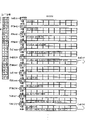
Fig. 4 is the block diagram of expression as data transmission device 10 structures of the data transmission device of liquid ejection data of the present invention.Fig. 5 is the sequential chart of the record data flow process in the modal representation data transmission device 10.
The record data of compression transmit (symbol T1) via system bus SB one word one word to the reception buffer 42DMA as " primary memory " by interface portion 27 from signal conditioning package 200.As mentioned above, the DMA transmission is if set transmission sources and transmission objectives address or transmission quantity in given register, then later on by MPU24, can carry out the transmission mode of data transmission with hardware at a high speed.Then, transmit (symbol T2) by system bus SB to DECU41DMA from reception buffer 42.Then, in the inside of DECU41, by decoding scheme 28 data of 1 word of compression are launched with hardware, the record data of expansion store (symbol T3) in the row cache device 281 into.
Launch and store into the moment that the record data of record data in storing row cache device 281 in the row cache device 281 reach given byte number, asynchronous with the data transmission of system bus SB one side, via the bit map area DMA transmission (symbol T4) of local bus LB to local storage 29.Then, record data as the bitmap image data in the bit map area that has stored local storage 29 into transmit (symbol T5) via local bus LB to DECU41 DMA again, transmit (symbol T6) via internal bus IB to a control part 33 DMA from DECU41, after storing in the register of control part 33 inside to the end, to record-header 62DMA transmission (symbol T7).
Like this, data transmission from reception buffer 42 (primary memory) to decoding scheme 28, from decoding scheme 28 to local storage 29 data transmission, 62 data transmission can be transmitted for DMA from local storage 29 to record-header, in view of the above, more high-speed data transmission becomes possibility, thereby better.In addition, by " primary memory " of stores compressed data constituted as circuit block with DECU41 as reception buffer 42, become possibility in identical ASIC4 with the high speed DMA transmission of 1 clock transfer data.In addition, reception buffer 42 can be set in ASIC4, the part of RAM22 is used as " primary memory ".
Fig. 6 is the block diagram of the DECU41 structure of expression conduct of the present invention " decoding unit ".
DMA transmission as S-DMA controller 411 control system bus SB one side of described " DMA transmitting device ".By S-DMA controller 411, record data one word one word that is stored in the compression in the reception buffer 42 is to launching processing controller 412DMA transmission.Launch processing controller 412 and be built-in with described decoding scheme 28 and row cache device 281.Launched with hardware by decoding scheme 281 1 words one word from the compression recording data of reception buffer 42 by S-DMA controller 411 1 words one word DMA transmission, the record data of expansion store in the row cache device 281.
Same L-DMA controller 413 as " DMA transmitting device " is controlled the DMA transmission of local bus LB one side.In addition, the local storage 29 of local storage controller 414 control linkages on local bus LB reading and writing.And, the moment of record data after the expansion of having stored given byte number in the row cache device 281, record data are by L-DMA controller 413 after being stored in the expansion in the row cache device 281, via local bus LB, transmitting non-synchronously with the DMA of system bus SB one side, DMA is transferred to local storage 29 by local storage controller 414.The record data that are transferred to after the expansion of local storage 29 store in the given bit map area of local storage 29.
The private bus that a DECU41 in the I-DMA controller 415 control ASIC4 of same conduct " DMA transmitting device " and a control part are 33 is the DMA transmission of internal bus IB.Store into after the expansion in the given bit map area of local storage 29 record data by I-DMA controller 415 by local storage controller 414, transmit control part 33 to the end via local bus LB and internal bus IB DMA, after storing in the register of control part 33 inside to the end, transmit to record-header 62DMA.
In addition, 29 DMA transmission is carried out burst transmissions by L-DMA controller 413 from row cache device 281 to local storage, carries out burst transmissions to the DMA of record-header 62 transmission by I-DMA controller 415 from local storage 29.As mentioned above, burst transmissions is when transmitting continuous data, by the steps such as appointment of address are omitted a part, before the whole end of transmissions of the data of given data block, occupies the data transfer mode that bus is transmitted.The moment of L-DMA controller 413 record data after the expansion of having stored given byte number in the buffer 281 of being expert at, one word of record data after the expansion of given byte number, one word before local storage 29 DMA transmit given byte number and finish, occupy local bus LB, carry out burst transmissions.I-DMA controller 415 the expansion in the bit map area that is stored in local storage 29 after record data by each data block of given byte number, a data block being occupied local bus LB before record-header 62 DMA end of transmissions, carry out burst transmissions with a word one word.
And, when 29 burst transmissions and from local storage 29 to record-header during 62 burst transmissions conflict from row cache device 281 to local storage, 62 burst transmissions is preferential from local storage 29 to record-header, 62 burst transmissions from local storage 29 to record-header, temporarily stop from row cache device 281 to local storage 29 burst transmissions, the ink jet action from the nozzle array of record-header 62 based on 62 the record data from local storage 29 to record-header can not disconnected midway.
Like this, transmit by occupying local bus LB in during before the data of record-header 62 having been transmitted given data block, can not take place because the requirement of the MPU24 of system bus SB one side and can't carry out the drawback of data transmission etc., so can carry out transmission at a high speed the record data of record-header 62.
Be illustrated in to Fig. 7 and Fig. 8 pattern DECU41 inside and launch the record data of compression, and store in the row cache device 281 by decoding scheme 28 usefulness hardware.In addition, the expression of Fig. 9 pattern ground is transmitted the record data after launching and storage to local storage 29 from row cache device 281.
In this embodiment, the record data of compression are by the compression of run length compress mode.The run length compress mode is well-known data compression mode, following simple declaration.The run length packed data is the packed data of byte boundary, and counting (1 byte) and data (1 byte or multibyte) become 1 group.Be that the run length packed data becomes at first be counting, necessarily have the structure of data then.Count value is that (negative constant) is 80H when above more than 128, mean the data of next byte of repetition and launch, by the number of obtaining from 257 numbers that deduct count value, repeat this counting next byte data and launch.And when count value be to be 7FH when following below 127, mean and after this counting, do not repeat that what follow is the data that remain untouched and launch, add 1 byte number of obtaining by this count value, do not repeat and remain untouched and launch the later data of this counting.
Then, the structure of description line buffer 281.Row cache device 281 has 8 words (16 byte) on the two sides memory block adds preparation memory block 1 word (2 byte) data storage area of totally 9 words, is respectively A face and B face.Store any one side side of the A face or the B face of row cache device 281 in order successively into the record data of decoding scheme 281 1 words one word expansion, when having stored given byte number, in this embodiment, in the moment when the expanding data of having stored 16 bytes, be stored in the another side side successively.In addition, the expanding data of 16 bytes of storage, stores in the given bit map area of local storage 29 to local storage 29DMA transmission via local bus LB as mentioned above.
Like this, row cache device 281 has the buffer area of record data after the expansion that can store 16 bytes on the two sides, and the record data that launched by decoding scheme 28 are stored in the one side side.And, when the moment of having stored 16 bytes, by the DMA transmitting device the expansion of one side side after record data when transmit with word unit, so the record data that can be launched by decoding scheme 28 in the storage of another side side are the expansion processing and the data transmission and processing of the parallel record data that compress of energy.
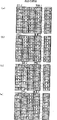
Then, enumerate an example of run length packed data, illustrate that this packed data is launched by decoding scheme 28, be stored in the row cache device 281, from the flow process of row cache device 281 to the record data of local storage 29 storages.
In reception buffer (primary memory) 42, storing from the record data of illustrated 24 words that begin from FEH (48 byte) run length compression.Record data one word one word of run length compression,, stores in the row cache device 281 after the hardware expansion to decoding scheme 28 DMA transmission via system bus SB.In this embodiment, the start address data of run length packed data is an even address, and the start address data of the data bitmap (view data) of local storage 29 1 sides is an even address.In addition, be 16 bytes from row cache device 281 to the byte number (1 row byte number) of local storage 29 DMA data block transmitted.
In addition, in the row cache device 281 of primary memory shown in Figure 7, DECU41 inside, the local storage 29 shown in Figure 9, left upper end is an even address, from left to right, becomes the high address in order, and is all same among the following figure.
Below, describe by the order of a word one word.At first, from reception buffer 42, (FEH is 01H) to decoding scheme 28 DMA of DECU41 inside transmission (transmission S1) for the compression recording data of 1 initial word.FEH is a counting, and 01H is data.The value FEH=254 of counting, because be more than 128, so 257-254=3 time, repeating data 01H and launching, a byte one byte is stored in the A face side of row cache device 281 successively.Then, to be transferred to the run length packed data in the decoding scheme 28 be 03H, 02H (transmission S2) to DMA.03H is a counting, and 02H is data.The value 03H=3 of counting is because be below 127, so begin to have the 3+1=4 byte not repeat and the data launched from next data of this counting.Promptly count the later data 02H of 03H, 78H, 55H, 44H and do not repeat, the expansion of remaining untouched, be stored in successively in the A face of row cache device 281 (transmission S2~S4).The FBH of a high position one side (odd address one side) of the digital data of DMA transmission is a counting in transmission S4, and the data of next byte repeat six times (257-251=6) and launch.
Then, to be transferred to the record data of the compression of decoding scheme 28 be FFH, FEH (transmission S5) to DMA.The FFH of low order address one side (even address one side) is data, is the data of counting FBH before.Therefore, repeat FFH six times and launch, store the A face side of row cache device 281 successively into.In addition, the FEH of high address one side (odd address one side) is a counting, repeats the data 3 times (257-254=3) of next byte and launches.Then, to be transferred to the record data of the compression of decoding scheme 28 be 11H, 06H (transmission S6) to DMA.The 11H of low order address one side (even address one side) is data, is the data of counting FEH before.Therefore, repeat 11H three times and launch, store the A face side of row cache device 281 successively into.In addition, the 06H of high address one side (odd address one side) is a counting, data of 7 bytes (6+1=7) (66H, 12H, 77H, 45H, 89H, 10H, 55H) after not repeating and intactly launching store B face side (the transmission S7~S10) of row cache device 281 successively into.
And after the i.e. expansion of 16 bytes of byte number that the A face side of the buffer 281 of being expert at has been stored 1 row the moment (moment of transmission S6) of record data, as 1 capable data block, 1 word, 1 word transmits to local storage 29DMA 16 bytes.At this moment, L-DMA controller 413 (Fig. 6) record data after the expansion of 1 row occupied local bus LB before local storage 29DMA end of transmission, carry out burst transmissions (transmission D1).The record data that are transferred to 1 row of local storage 29 are beginning with the even address, from low order address are, 1 word, 1 word stores in the given bit map area of local storage 29 (Fig. 9 (a)) successively.
Then, to be transferred to the record data of the compression of decoding scheme 28 be 10H, FAH (transmission S11) to DMA.The 10H of low order address one side (even address one side) is data, is the data of counting FBH before.Therefore, repeat 10H six times and launch, store the B face side of row cache device 281 successively into.In addition, the FAH of high address one side (odd address one side) is a counting, repeats the data 7 times (257-250=7) of next byte and launches.Then, to be transferred to the record data of the compression of decoding scheme 28 be 20H, 08H (transmission S12) to DMA.The 20H of low order address one side (even address one side) is data, is the data of counting FAH before.Therefore, repeat 20H seven times and launch, store the B face side of row cache device 281 successively into.In addition, the 08H of high address one side (odd address one side) is a counting, data of 9 bytes (8+1=9) after not repeating (12H, 13H, 77H, 14H, 15H, 16H, 17H, 18H, 19H, 20) and intactly launching, (Fig. 8 transmits S13~S17) to store the A face side of row cache device 281 successively into.
And after the i.e. expansion of 16 bytes of byte number that the B face side of the buffer 281 of being expert at has been stored 1 row the moment (moment of transmission S12) of record data, as 1 capable data block, 1 word, 1 word transmits to local storage 29 DMA 16 bytes.At this moment, L-DMA controller 413 (Fig. 6) record data after the expansion of 1 row occupied local bus LB before local storage 29 DMA end of transmissions, carry out burst transmissions (transmission D2).The record data that are transferred to 1 row of local storage 29 are beginning with the even address, from low order address are, 1 word, 1 word stores in the given bit map area of local storage 29 (Fig. 9 (b)) successively.
Then, to be transferred to the record data of the compression of decoding scheme 28 be 11H, 02H (transmission S18) to DMA.The 11H of low order address one side (even address one side) is data, is the data of counting FDH before (high address one side of transmission S17).Therefore, repeat 11H three times (257-254=3) and launch, store the A face side of row cache device 281 successively into.In addition, the 02H of high address one side (odd address one side) is a counting, data of 3 bytes (2+1=3) (98H, B0H, F2H) the repetition after and intactly launching, and the B face side that stores row cache device 281 successively into (is transmitted S19~S20).
And after the i.e. expansion of 16 bytes of byte number that the A face side of the buffer 281 of being expert at has been stored 1 row the moment (moment of transmission S18) of record data, as 1 capable data block, 1 word, 1 word transmits to local storage 29 DMA 16 bytes.At this moment, L-DMA controller 413 (Fig. 6) record data after the expansion of 1 row occupied local bus LB before local storage 29 DMA end of transmissions, carry out burst transmissions (transmission D3).The record data that are transferred to 1 row of local storage 29 are beginning with the even address, from low order address are, 1 word, 1 word stores in the given bit map area of local storage 29 (Fig. 9 (c)) successively.
Then, to be transferred to the record data of the compression of decoding scheme 28 be ABH, 03H (transmission S21) to DMA.The ABH of low order address one side (even address one side) is data, is the data of counting FCH before (high address one side of transmission S20).Therefore, repeat ABH five times (257-252=5) and launch, store the B face side of row cache device 281 successively into.In addition, the 03H of high address one side (odd address one side) is a counting, data of 4 bytes (3+1=3) (FFH, FEH, FCH, FDH) the repetition after and intactly launching, and the B face side that stores row cache device 281 successively into (is transmitted S22~S23).
Then, to be transferred to the record data of the compression of decoding scheme 28 be FEH, FFH (transmission S24) to DMA.The FEH of low order address one side (even address one side) is a counting, and high address one side (odd address one side) FFH is the data of counting FEH.Therefore, repeat FFH three times (257-254=3) and launch, store the B face side of row cache device 281 successively into.And after the i.e. expansion of 16 bytes of byte number that the B face side of the buffer 281 of being expert at has been stored 1 row the moment (moment of transmission S24) of record data, as 1 capable data block, 1 word, 1 word transmits to local storage 29 DMA 16 bytes.At this moment, L-DMA controller 413 (Fig. 6) record data after the expansion of 1 row occupied local bus LB before local storage 29 DMA end of transmissions, carry out burst transmissions (transmission D4).
The record data that are transferred to 1 row of local storage 29 are beginning with the even address, from low order address are, 1 word, 1 word stores in the given bit map area of local storage 29 (Fig. 9 (d)) successively.And, when in local storage 29, having stored 1 main sweep circulation, spraying the record data of data bitmap part of ink, transmit to record-header 62DMA from local storage 29.At this moment, I-DMA controller 415 (Fig. 6) occupied local bus LB and carries out burst transmissions before the record data that transmitted the data bitmap part of spraying ink in 1 main sweep circulation to a control part 33DMA.
Like this, by launched by decoding scheme 28 usefulness hardware by the processing of program in the past, can carry out the expansion of the record data of compression at a high speed and handle with the record data of software expansion compression.In addition, because the compression recording data that launches by program 1 byte 1 byte is launched with word unit's (2 byte) in the past, the expansion of the record data that can compress is more at a high speed handled.And, by have 2 of system bus SB and local bus LB etc. independently bus, be connected the structure of the local storage 29 on the local bus LB, can carry out from local storage 29 to record-header 62 data transmission with system bus SB one side in local bus LB one side asynchronously.In view of the above, can not take place because from MPU24 to ROM21 or the visit of RAM22 etc., be interrupted, produce the transmission delay of record data, the decline of record execution speed to the transmission of the record data of record-header 62.By the DMA transmission, high-speed data transmission becomes possibility.
Therefore, the high speed that can realize the record data of compression launch to be handled and to the high speed data transfer of record-header 62, so the record execution speed of inkjet recording device 50 is compared with the past, tremendous raising can be arranged.By the way, be that the data rate to record-header 62 before and after the 1M byte per second is passed through data transmission device 10 of the present invention in the prior art, can bring up to 8~101M byte per second.In addition,, then no matter carry out what kind of high speed data transfer, also can only obtain the record execution speed of the data-handling capacity of record-header 62, so be necessary to dispose record-header 62 certainly with enough processing poweies if the data-handling capacity of record-header 62 is low.
In addition, embodiment 2 as inkjet recording device 50 of the present invention, enumerated on the basis of the above embodiments 1, from the record data of DECU41 after local storage 29DMA transmission launches, when given bit map area is stored, not to store (to horizontal storage) successively, but the data conversion of 1 row is vertically, stores from the low order address of bit map area, make for record-header 62, become suitable data and arrange.
The record data that the expression of Figure 10 pattern ground is transmitted after launching to local storage 29 from row cache device 281, and storage have been represented the data conversion of 1 row is state vertical and storage.
In the bit map area of the local storage 29 of DMA transmission objectives, expansion processing controller 412 (Fig. 6) with DECU41 inside, to being stored in the record data after the expansion in the row cache device 281, the transmission objectives address set respectively in each word, the data configuration storage that makes 1 row is in the vertical.And, the L-DMA controller 413 (Fig. 6) of DECU41 inside is individual other transmission objectives address setting the transmission objectives address of DMA transmission, and one word of the record data after the expansion that is stored in the row cache device 281, one word is transmitted (data rearrangement device) to local storage 29DMA.
Like this, when from row cache device 281 during to the record data of local storage 29DMA transmission 1 row (16 byte), reset by the record data after launching in the inside of DECU41, compare with the rearrangement of as in the past, carrying out in the storer in order with program 1 byte 1 byte, can carry out the rearrangement of necessary record data in moment, so can carry out the rearrangement of record data at a high speed.
Further, embodiment 3 as inkjet recording device 50 of the present invention, enumerated on the basis of the above embodiments 1 or embodiment 2, when the start address data with record data of the run length compression in being stored in reception buffer 42 is odd address, make that to begin 1 byte data be invalid invalid data mask treating apparatus to the digital data that begins data that comprises of the run length compression of decoding scheme 28 DMA transmission from reception buffer 42.
Figure 11 and the expression of Figure 12 pattern ground are launched the record data of compression by decoding scheme 28 with hardware, to 281 storages of row cache device, the situation the when start address data of the record data of expression compression is odd address.
The beginning byte data (FEH) that is stored in the record data of the run length compression in the reception buffer 42 (primary memory) is stored in the high address (odd address) of this digital data that begins.Promptly in comprising this low order address that begins the digital data of byte data (even address), storing and the irrelevant data (AAH) of record data., if transmit to decoding scheme 28 1 words one word DMA from reception buffer 42, then can't be with even address for beginning transmission.Therefore,, then under the state that has comprised extraneous data, launched record data, can't correctly launch the record data that compress if by decoding scheme 28 the beginning digital data of the record data of run length compression is launched, handled with hardware like this.
Therefore, in launching processing controller 412 (Fig. 6), the irrelevant byte data mask of the low order address that comprises the digital data that begins byte data (even address), it is invalid to become, and launches with decoding scheme 28 again.Use decoding scheme 28 to launch beginning 1 word if promptly remain untouched, then AAH is counting, and FEH is data, is invalid by making extraneous data AAH still, and just can make FEH is counting, correctly launches.
Then, to be transferred to the record data of the compression of decoding scheme 28 be 01H, 03H (transmission S31) to DMA.The 01H of low order address one side (even address one side) is data, is the data of counting FEH before.Therefore, repeat 01H three times (257-254=3) and launch, store the A face side of row cache device 281 successively into.In addition, the 03H of high address one side (odd address one side) is a counting, and later 4 bytes (3+1) data (02H, 78H, 55H, 44H) do not repeat, and intactly launches, and stores A face side (the transmission S32~S33) of row cache device 281 successively into.Below, with step similarly to Example 1,1 word, 1 word launches the record data of run length compression, store A face side (the transmission S32~S54) of row cache device 281 successively into, the moment of record data after the expansion of the byte number (16 byte) of having stored 1 row is to local storage 29 DMA transmission (transmission D1~D4).In addition, whether the start address data that is stored in the record data of the run length compression in the reception buffer 42 is that odd address can be by the judgements of being carried out by MPU24 such as firmware program.
Like this, be odd address even be stored in the start address data of the record data of the run length compression in the reception buffer 42, also can correctly launch from the beginning beginning of usefulness correctly of the record data of run length compression by decoding scheme 28 usefulness hardware.
Figure 13 and Figure 14 pattern ground have been represented by decoding scheme 28 record data of compression to be launched with hardware, store in the row cache device 281, have represented in described embodiment 1 or embodiment 2 situation when byte number of 1 row is 15 bytes.In addition, having represented in embodiment 4 to Figure 15 pattern, the record data after launching are transmitted to local storage 29 from row cache device 281, is line translation extended spread, and storage, has represented to Figure 16 pattern to be not that extended spread is stored to line translation.
As mentioned above, record data after the expansion transmit to local storage 29 1 words one word DMA from row cache device 281, so during the record data after the bit map area storage of local storage 29 launches also is that a word one word carries out, can't be from the record data of DECU41 to local storage 29DMA transmission odd bytes.Therefore, in launching processing controller 412 (Fig. 6), the byte number of 1 row of row cache device 281 is set at odd bytes, be 15 bytes in this embodiment, the moment of record data transmits to local storage 29DMA after the expansion that the A face side or the B face side of the buffer 281 of being expert at have been stored 15 bytes.Therefore, high address one side (odd address one side) that comprises the digital data of the record data that hang down 15 bytes has been carried out DMA transmission (data storage end position shift unit) under the state of 00H.
In transmission S61~S64, identical with transmission S1~S4 of embodiment 1 (Fig. 7), so omitted explanation.Then, to be transferred to the record data of the compression of decoding scheme 28 be FFH, FFH (transmission S65) to DMA.The FFH of low order address one side (even address one side) is data, is the data of counting FBH before.Therefore, repeat FFH six times (257-251) and launch, store the A face side of row cache device 281 successively into.In addition, the FFH of high address one side (odd address one side) is a counting, repeats data 2 times (257-255=2) then and launches, and stores the A face side of row cache device 281 successively into.
Then, to be transferred to the record data of the compression of decoding scheme 28 be 11H, 06H (transmission S66) to DMA.The 11H of low order address one side (even address one side) is data, is the data of counting FFH before.Therefore, repeat FFH twice (257-255=3) and launch, store the A face side of row cache device 281 successively into.In addition, the 06H of high address one side (odd address one side) is a counting, data of 7 bytes (6+1=7) (66H, 12H, 77H, 45H, 89H, 10H, 55H) after not repeating and intactly launching store B face side (the transmission S67~S70) of row cache device 281 successively into.
And after the i.e. expansion of 15 bytes of byte number that the A face side of the buffer 281 of being expert at has been stored 1 row the moment (moment of transmission S66) of record data, as 1 capable data block, 1 word, 1 word transmits to local storage 29DMA 15 bytes.At this moment, L-DMA controller 413 (Fig. 6) record data after the expansion of 1 row occupied local bus LB before local storage 29DMA end of transmission, carry out burst transmissions (transmission D1).The record data that are transferred to 1 row of local storage 29 are beginning with the even address, from low order address are, 1 word, 1 word stores in the given bit map area of local storage 29 (Figure 15 (a)) successively.In addition, if be line translation extended spread, storage go down (Figure 16 (a)) successively like this.Below, equally the record Shanghai opera of run length compression is launched (transmission S71~S84) by decoding scheme 28 usefulness hardware, the moment of the record data after the expansion of having stored 15 bytes in the buffer 281 of being expert at is to local storage 29DMA transmission (transmission D2~D4).
Figure 17 and Figure 18 pattern ground have been represented by decoding circuit 28 record data of compression to be launched with hardware, store in the row cache device 281, have represented in described embodiment 3 situation when byte number of 1 row is 15 bytes.
S91~S94 is identical with transmission S31~S34 of embodiment 2 (Figure 11) in transmission, so omit explanation.Then, to be transferred to the record data of the compression of decoding scheme 28 be FFH, 11H (transmission S95) to DMA.The FFH of low order address one side (even address one side) is a counting, and the 11H of high address one side (odd address one side) is data.Therefore, repeat 11H twice (257-255=2) and launch, store the A face side of row cache device 281 successively into.
And after the i.e. expansion of 15 bytes of byte number that the A face side of the buffer 281 of being expert at has been stored 1 row the moment (moment of transmission S95) of record data, as 1 capable data block, 1 word, 1 word transmits to local storage 29 DMA 15 bytes.At this moment, L-DMA controller 413 (Fig. 6) record data after the expansion of 1 row occupied local bus LB before local storage 29 DMA end of transmissions, carry out burst transmissions (transmission D1).The record data that are transferred to 1 row of local storage 29 are beginning with the even address, from low order address are, 1 word, 1 word is line translation extended spread by described data rearrangement device, store in the given bit map area of local storage 29 (Figure 15 (a)).In addition, if be not line translation extended spread, just remain untouched and store down (Figure 16 (a)) successively.Below, equally the record number of run length compression is launched by decoding scheme 28 usefulness hardware that (transmission S71~S84), the moment of the record data after the expansion of having stored 15 bytes in the buffer 281 of being expert at is to local storage 29DMA transmission (transmission D2~D4).
Like this, the moment of record data after the expansion of having stored odd bytes in the row cache device 281, by transmitting to local storage 29 DMA, high address one side of last digital data is to transmit under the state of 00H, so can make record data after the expansion in the bit map area that is stored in local storage 29 shown in Figure 15 (d) and 16 (d), make last 1 byte of 1 row become 00H, start address data is an even address, the record data of 1 row become odd bytes ground, record data are stored in the bit map area of local storage 29.
Embodiment 5 as inkjet recording device 50 of the present invention, enumerated on any one the basis of the above embodiments 2~embodiment 4, making the start address data of the record data of 1 row is odd address, record data is stored in the bit map area of local storage 29.
The a plurality of nozzles that are configured on the women's head-ornaments of record-header 62 are classified the ink color that each nozzle rows decision is sprayed as.And be stored in the data that record data in the bit map area of local storage 29 become each corresponding with each nozzle rows in each row ink color.And in the device of the ink jet timing slip that this nozzle rows of correction causes at interval, being necessary to make start address sometimes is odd address, and the record data of 1 row are stored in the bit map area of local storage 29.
; as mentioned above; because 1 word, 1 word transmits to decoding scheme 28DMA from reception buffer 42; record data after the expansion always are beginning with the even address; be stored in the bit map area of local storage 29; so under intact situation, can't with the odd address beginning, the stored record data.Therefore, in launching processing controller 412 (Fig. 6), when storing in the row cache device 281, under the state of the 0th byte of empty row cache device 281, open storage (data storage starting position shift unit) to record data that launch by decoding scheme 28 from first byte.After the expansion of promptly having carried out the record data of compression in decoding scheme 28 is handled, record data after handle launches are when 281 storages of row cache device, under the state of the 0th byte of empty row cache device 281, open storage from first byte, record data after the expansion that is stored in the row cache device 281 are transmitted to the bit map area DMA of local storage 29 transmission since the 0th byte.
Figure 19 and Figure 20 pattern ground have been represented by decoding scheme 28 record data of compression to be launched with hardware, store in the row cache device 281, represented in described embodiment 2, for row cache device 281 be empty state from the 0th byte under, the situation during record data after first byte is stored expansion.In addition, having represented that Fig. 2 l pattern 16 bytes of 1 row are launched the back record data to be transmitted to local storage 29 from row cache device 281, is line translation extended spread, is that beginning is stored with the odd address.
As mentioned above, the memory block of 8 words (16 byte) that row cache device 281 all has except A face and B face, the preparation memory block that also has 1 word (2 byte).Be expert at the 0th byte of A face side of buffer 281 of the record data that launched by decoding scheme 28 1 words one word is under the empty state, to store since first byte.And by making the 0th byte for empty, the record data of the 16th byte of reading from the memory block are stored in the preparation memory block.
In the moment of the record data after the A face side of the buffer 281 of being expert at has been stored the expansion of 16 bytes, the record data of total 18 bytes (9 word) of 16 bytes of memory districts and preparation memory block are as the data block of 1 row, and 1 word, 1 word transmits to local storage 29 DMA.At this moment, L-DMA controller 413 (Fig. 6) record data after the expansion of 1 row occupied local bus LB before local storage 29DMA end of transmission, carry out burst transmissions (transmission D1).The record data that are transferred to 1 row of local storage 29 are beginning with the even address, from low order address are, 1 word, 1 word is line translation extended spread by described data rearrangement device, store in the given bit map area of local storage 29 (Figure 21 (a)).Therefore, beginning to have added under the state of 1 byte of null data,, be stored in the even address of bit map area, so the record data of 1 row become the state that the beginning data begin to store from odd address to local storage 29 DMA transmission.
Then, equally the record data of run length compression are launched by decoding scheme 28 usefulness hardware, when 16 bytes of having stored 1 row in the buffer 281 of being expert at are launched moment of back record data, transmit (D2~D4) to local storage 29DMA.In addition, the explanation of the explanation of transmission S121~S144 and transmission S1~S24 shown in Figure 7 is same, so omit.
Like this, be expert at the 0th byte of A face side of buffer 281 of the record data that launched by decoding scheme 28 1 words one word is under the empty state, store since first byte, the moment of record data after the expansion of having stored 16 bytes, by transmitting to local storage 29DMA, be to transmit under the state of 00H with low order address one side of initial digital data, so be stored in record data after the expansion in the bit map area of local storage 29 shown in Figure 21 (d), initial 1 byte of 1 row becomes 00H, can make the start address of the record data of 1 row is odd address, record data is stored in the bit map area of local storage 29.
In addition, Figure 22 and Figure 23 pattern ground have been represented by decoding scheme 28 record data of compression to be launched with hardware, store in the row cache device 281, represented in described embodiment 4, the 0th byte of row cache device 281 is under the empty state, the situation when first byte is launched the record data after launching.In addition, having represented that Figure 24 pattern 15 bytes of 1 row are launched the back record data to be transmitted to local storage 29 from row cache device 281, is line translation extended spread, is that beginning is stored with the odd address.
Like this, the byte number of 1 row is 15 bytes, can be odd bytes.Therefore, shown in Figure 24 (d), the 1 initial byte of 1 row is 00H, and can make start address data is odd address, and the record data of 1 row, 15 bytes are stored in the bit map area of local storage 29.
In addition, Figure 25 and Figure 26 pattern ground have been represented by decoding scheme 28 record data of compression to be launched with hardware, store in the row cache device 281, represented in described embodiment 3, the 0th byte of row cache device 281 is under the state of sky, the record data after launching are launched the situation the when record data of 1 row are 16 bytes from first byte.Equally, Figure 27 and Figure 28 have represented that in described embodiment 3 the 0th byte of row cache device 281 is under the state of sky, the record data after launching are launched the situation the when record data of 1 row are 15 bytes from first byte.
Like this, be after record data that beginning is stored in the compression in the reception buffer 42 are launched by decoding scheme 28, to be that beginning is stored the record data of 1 row, 16 bytes or 15 bytes in the bit map area of local storage 29 into the odd address with the odd address.
As the embodiment 6 of inkjet recording device 50 of the present invention, enumerated on any one basis of the above embodiments 1~embodiment 5, the record data after launching are stored in two different bit map area of local storage 29.Having represented to Figure 29 pattern the record data after the 1 row expansion are transmitted to local storage 29 from row cache device 281, is line translation extended spread, is beginning with the even address, stores in two different bit map area.
Data bitmap after launching can't form adjacent ink dot at sub scanning direction Y simultaneously in 1 main sweep when sub scanning direction Y is also littler than the interval of the adjacent nozzle array of sub scanning direction Y, so form when different main sweep actions., the data bitmap that is launched by decoding scheme 28 is in the adjacent continuously arranged data structure of ink dot data that forms of sub scanning direction Y, so the data bitmap after launching can't remain untouched to record-header 62 transmission, carry out record.Therefore, be necessary to cut apart the record data after the expansion, in the adjacent ink dot data storage of sub scanning direction Y in different bit map area, can be when different main sweeps, to record-header 62 transmission.
Therefore, two different bit map area are set in advance in local storage 29.Here, be respectively image 1, image 2.In the bit map area of the local storage 29 of DMA transmission objectives,,, the data of 1 row alternately are stored in image 1 and the image 2 to every word individual settings transmission objectives address to storing record data after the expansion in the row cache device 281 into by launching processing controller 412.And, the L-DMA controller 413 (Fig. 6) of DECU41 inside is this other transmission objectives address setting the transmission objectives address of DMA transmission, and 1 word of the record data after the expansion that is stored in the row cache device 281,1 word is transmitted (data splitting block) to local storage 29DMA.
At first, the A face side of the buffer 281 of being expert at has been stored the moment of record data after the expansion of 1 row, 16 bytes, and the record data of 1 row to local storage 29 DMA transmission (transmission D1), are stored in the image 1 (Figure 29 (a)).Then, stored the moment of record data after the expansion of 1 row, 16 bytes when the B face side of the buffer 281 of being expert at, the record data of 1 row to local storage 29 DMA transmission (transmission D2), have been stored in the image 2 (Figure 29 (b)).Then, the A face side of the buffer 281 of being expert at has been stored the moment of record data after the expansion of 1 row, 16 bytes, and the record data of 1 row to local storage 29DMA transmission (transmission D3), are stored in the image 1 (Figure 29 (c)).Then, stored the moment of record data after the expansion of 1 row, 16 bytes when the B face side of the buffer 281 of being expert at, the record data of 1 row to local storage 29DMA transmission (transmission D4), have been stored in the image 2 (Figure 29 (d)).
Like this, after launching to have handled the record data of compression, record data after the expansion that is stored in the row cache device 281 by the different bit map area DMA transmission of each row to local storage 29, are made sub scanning direction Y go up adjacent ink dot and form when different main sweeps.In view of the above, the expansion of the record data that can compress at a high speed by hardware handles handle (decoding scheme 28) and launch after the cutting apart of record data (expansion processing controller 412).In addition, having represented to Figure 30 pattern the record data after the expansion of 1 row, 16 bytes are transmitted to local storage 29 from row cache device 281, is not line translation extended spread, remains untouched even address to start with, to two different bit map area storages.
In addition, having represented to Figure 31 pattern the record data after the expansion of 1 row, 15 bytes are transmitted to local storage 29 from row cache device 281, is line translation extended spread, even address to start with, and to two different bit map area storages.Having represented to Figure 32 pattern the record data after the expansion of 1 row, 15 bytes are transmitted to local storage 29 from row cache device 281, is not line translation extended spread, remains untouched even address to start with, to two different bit map area storages.
Like this, making the byte number of 1 row is odd bytes, the moment of the record data after the expansion of having stored odd bytes in the row cache device 281, by to local storage 29 DMA transmission, with high address one side of last digital data be 00H state transfer the record data of 1 row.Therefore, record data become 00H in last 1 byte of 1 row after being stored in the expansion in the bit map area of local storage 29, start address data is an even address, and the record data of 1 row become odd bytes, stores into respectively in 2 different bit map area such as image 1 and image 2 grades by each row.
In addition, having represented to Figure 33 pattern the record data after the expansion of 1 row, 16 bytes are transmitted to local storage 29 from row cache device 281, is line translation extended spread, odd address to start with, and to two different bit map area storages.Having represented to Figure 34 pattern the record data after the expansion of 1 row, 15 bytes are transmitted to local storage 29 from row cache device 281, is line translation extended spread, odd address to start with, and to two different bit map area storages.
Like this, be expert at the 0th byte of A face side of buffer 281 of the record data that launched by decoding scheme 28 1 words one word is under the empty state, store since first byte, the moment of record data after the expansion of having stored 16 bytes, by transmitting to local storage 29DMA, be to transmit under the state of 00H in low order address one side of initial digital data, so initial 1 byte of 1 of record data row becomes 00H after the expansion of storing in the bit map area of local storage 29, the start address data of the record data of 1 row is become odd address, respectively data are stored in 2 different bit map area such as image 1 and image 2 grades by every row.
As the embodiment 7 of inkjet recording device 50 of the present invention, enumerated in any one of described embodiment 1~embodiment 6, when the record data in being stored in reception buffer 42 are unpacked data, do not launch to handle, store in the bit map area.Represented to Figure 35 pattern incompressible record data are remained untouched and stored in the row cache device 281, to the state of local storage 29DMA transmission.
Like this, when the record data that transmit to reception buffer 42 from signal conditioning package 200 are unpacked data, launch to handle without decoding scheme 28,1 word, 1 word that remains untouched stores in the row cache device 281.Then, same during with the record data that launch compression by decoding scheme 28, in launching processing controller (Fig. 6), as described shown in embodiment 2~embodiment 6, the byte number of 1 row is set at 16 bytes or 15 bytes, carries out the rearrangement of record data, or to make start address be odd address, store in the local storage 29, or store in two different bit map area.
In addition, the present invention is not limited to described embodiment, in the invention scope of describing in the scope of claim, various distortion can be arranged, and they are also contained in the scope of the present invention certainly.
Claims (12)
1. the data transmission device of a liquid ejection data comprises:
The independent bus line of two systems of system bus and local bus;
Be connected the primary memory on the described system bus with can transmitting data;
Be connected the local storage on the described local bus with can transmitting data;
Be connected between described system bus and the described local bus, make them can transmit data each other, have and to go the decoding unit of the decoding scheme that the liquid ejection data that launches launches with hardware being compressed to;
With the word is the buffer of unit storage by the liquid ejection data of this decoding scheme expansion; And the jet head liquid that connects described buffer and atomizing of liquids.
2. the data transmission device of liquid ejection data according to claim 1 is characterized in that:
The liquid ejection data of described compression is the run length data, and described decoding scheme is the decoding scheme that launches the run length packed data with hardware.
3. liquid injection apparatus with data transmission device of the described liquid ejection data of claim 1.
4. the data transmission device of a liquid ejection data comprises:
The independent bus line of two systems of system bus and local bus;
Be connected the primary memory on the described system bus with can transmitting data;
Be connected the local storage on the described local bus with can transmitting data;
Be connected between described system bus and the described local bus, make them transmit data each other, have and to go the decoding scheme that the liquid ejection data that launches launches with hardware being compressed to, with the row cache device of word unit's storage by the liquid ejection data of this decoding scheme expansion, from described primary memory be compressed to can go the liquid ejection data that launches to described decoding scheme DMA transmission and the liquid ejection data that this row cache device, launches with word unit to described local storage DMA transmission and the liquid ejection data after the expansion that is stored in described local storage DMA successively is transferred to the decoding unit of the DMA transmitting device in the register of jet head liquid.
5. the data transmission device of liquid ejection data according to claim 4 is characterized in that:
The register of described primary memory, described decoding unit and described jet head liquid is built among the ASIC as circuit block respectively, and the register of described decoding unit and described jet head liquid is connected by the private bus of described ASIC inside.
6. according to the data transmission device of claim 4 or 5 described liquid ejection datas, it is characterized in that:
Described row cache device has the buffer area that can store the expanding data of given number of words on the two sides, store the liquid ejection data that launches by described decoding scheme successively in the one side side, in the moment of the expanding data of having stored given number of words, store the liquid ejection data that launches with described decoding scheme successively in the another side side, and, expanding data is transmitted to described local storage DMA by given number of words in the moment of the expanding data of having stored given number of words.
7. the data transmission device of liquid ejection data according to claim 6 is characterized in that:
The liquid ejection data of described compression is the run length data, and described decoding scheme is the decoding scheme that launches the run length packed data with hardware.
8. the data transmission device of liquid ejection data according to claim 4 is characterized in that:
Undertaken by burst transmissions to the data transmission of described local storage and register from the described decoding unit of described local bus from described local storage to described jet head liquid.
9. the data transmission device of liquid ejection data according to claim 4 is characterized in that:
Described decoding unit does not have the non-compressed liquid jet data from described primary memory DMA transmission is carried out the hardware expansion with described decoding scheme, and the device of in described row cache device, storing.
10. the data transmission device of liquid ejection data according to claim 9 is characterized in that:
The liquid ejection data of described compression is the run length data, and described decoding scheme is the decoding scheme that launches the run length packed data with hardware.
11. liquid injection apparatus with data transmission device of the described liquid ejection data of claim 6.
12. liquid injection apparatus with data transmission device of the described liquid ejection data of claim 9.
Applications Claiming Priority (4)
| Application Number | Priority Date | Filing Date | Title |
|---|---|---|---|
| JP2002245324 | 2002-08-26 | ||
| JP2002245324 | 2002-08-26 | ||
| JP2003175095 | 2003-06-19 | ||
| JP2003175095A JP4182343B2 (en) | 2002-08-26 | 2003-06-19 | Data transfer device for liquid ejection data, liquid ejection device |
Publications (2)
| Publication Number | Publication Date |
|---|---|
| CN1489072A CN1489072A (en) | 2004-04-14 |
| CN100495372C true CN100495372C (en) | 2009-06-03 |
Family
ID=31497672
Family Applications (2)
| Application Number | Title | Priority Date | Filing Date |
|---|---|---|---|
| CNU032053851U Expired - Fee Related CN2718668Y (en) | 2002-08-26 | 2003-08-26 | Data transmitting device for liquid spraying data, liquid spraying device |
| CNB031550339A Expired - Fee Related CN100495372C (en) | 2002-08-26 | 2003-08-26 | Liquid injection data transmission device, liquid injection device |
Family Applications Before (1)
| Application Number | Title | Priority Date | Filing Date |
|---|---|---|---|
| CNU032053851U Expired - Fee Related CN2718668Y (en) | 2002-08-26 | 2003-08-26 | Data transmitting device for liquid spraying data, liquid spraying device |
Country Status (5)
| Country | Link |
|---|---|
| US (1) | US7167932B2 (en) |
| EP (1) | EP1394683B1 (en) |
| JP (1) | JP4182343B2 (en) |
| CN (2) | CN2718668Y (en) |
| DE (1) | DE60311370T2 (en) |
Families Citing this family (3)
| Publication number | Priority date | Publication date | Assignee | Title |
|---|---|---|---|---|
| JP4492362B2 (en) * | 2005-01-14 | 2010-06-30 | セイコーエプソン株式会社 | Image forming apparatus capable of improving image quality |
| JP4595585B2 (en) * | 2005-02-24 | 2010-12-08 | セイコーエプソン株式会社 | Image processing apparatus, image processing method, program, and printing apparatus |
| JP5851201B2 (en) * | 2011-10-28 | 2016-02-03 | 理想科学工業株式会社 | Image processing apparatus and printing system |
Family Cites Families (11)
| Publication number | Priority date | Publication date | Assignee | Title |
|---|---|---|---|---|
| US4918624A (en) * | 1988-02-05 | 1990-04-17 | The United States Of America As Represented By The United States Department Of Energy | Vector generator scan converter |
| JPH03251053A (en) | 1990-02-26 | 1991-11-08 | Nippon Densan Corp | Quick charger and quick charging method |
| US5533175A (en) * | 1994-03-04 | 1996-07-02 | Destiny Technology Corporation | Low cost page printer system and method |
| JPH0911554A (en) * | 1995-06-27 | 1997-01-14 | Brother Ind Ltd | Host base printer |
| US6388760B2 (en) * | 1996-02-26 | 2002-05-14 | Brother Kogyo Kabushiki Kaisha | Host-based printing system and printing control method thereof |
| US5937152A (en) * | 1996-04-16 | 1999-08-10 | Brother Kogyo Kabushiki Kaisha | Printer with buffer memory |
| JP4531871B2 (en) | 1997-10-30 | 2010-08-25 | 富士通セミコンダクター株式会社 | Image information processing apparatus and encoding apparatus |
| US6167001A (en) * | 1999-01-26 | 2000-12-26 | Xilinx, Inc. | Method and apparatus for measuring setup and hold times for element microelectronic device |
| JP2001063058A (en) * | 1999-08-24 | 2001-03-13 | Canon Inc | Recording system, recorder, information processor and control method thereof, computer readable memory |
| US20030081244A1 (en) * | 2001-10-30 | 2003-05-01 | Clouthier Scott C. | Method and apparatus for processing data in an imaging device |
| US6819322B2 (en) * | 2002-01-04 | 2004-11-16 | Hewlett-Packard Development Company, L.P. | Method and apparatus for detecting potential lock-up conditions in a video graphics controller |
-
2003
- 2003-06-19 JP JP2003175095A patent/JP4182343B2/en not_active Expired - Fee Related
- 2003-08-26 DE DE60311370T patent/DE60311370T2/en not_active Expired - Lifetime
- 2003-08-26 EP EP03018736A patent/EP1394683B1/en not_active Expired - Fee Related
- 2003-08-26 CN CNU032053851U patent/CN2718668Y/en not_active Expired - Fee Related
- 2003-08-26 CN CNB031550339A patent/CN100495372C/en not_active Expired - Fee Related
- 2003-08-26 US US10/649,296 patent/US7167932B2/en not_active Expired - Fee Related
Also Published As
| Publication number | Publication date |
|---|---|
| JP2004145857A (en) | 2004-05-20 |
| DE60311370T2 (en) | 2007-11-08 |
| CN1489072A (en) | 2004-04-14 |
| JP4182343B2 (en) | 2008-11-19 |
| US20040083313A1 (en) | 2004-04-29 |
| EP1394683A3 (en) | 2005-08-31 |
| DE60311370D1 (en) | 2007-03-15 |
| US7167932B2 (en) | 2007-01-23 |
| CN2718668Y (en) | 2005-08-17 |
| EP1394683A2 (en) | 2004-03-03 |
| EP1394683B1 (en) | 2007-01-24 |
Similar Documents
| Publication | Publication Date | Title |
|---|---|---|
| EP1010133B1 (en) | Image storage and retrieval for a printer | |
| US8403447B1 (en) | Fluid jetting with delays | |
| EP1864813B1 (en) | Ink-jet recording apparatus and data transfer apparatus | |
| CN100495372C (en) | Liquid injection data transmission device, liquid injection device | |
| US5570464A (en) | Controller for a recording apparatus | |
| US7458652B2 (en) | Data transferring apparatus for transferring liquid ejection data and a liquid ejecting apparatus | |
| CN1310158C (en) | A data transferring apparatus for transferring liquid ejection data and a liquid ejecting apparatus | |
| JP2006264274A (en) | Uncompressing circuit, uncompressing method and printer | |
| CN100364287C (en) | Data transferring apparatus for transferring liquid ejection data and a liquid ejecting apparatus | |
| JP3424530B2 (en) | Printer device | |
| JP4359751B2 (en) | Data transfer device for liquid ejection data, liquid ejection device | |
| JP4359752B2 (en) | Data transfer device for liquid ejection data, liquid ejection device | |
| JP4412478B2 (en) | Data transfer device for liquid ejection data, liquid ejection device | |
| JP4336952B2 (en) | Data transfer device for liquid ejection data, liquid ejection device | |
| JP2005088574A (en) | Apparatus for transferring liquid ejection data, and liquid ejection apparatus | |
| JP4038639B2 (en) | Printer and its image data transfer method | |
| JPH01140276A (en) | Portable recording medium processor | |
| JP2005035293A (en) | Data transferring apparatus for liquid ejection data, and liquid ejecting apparatus | |
| JP2005028874A (en) | Liquid ejection data transfer unit, liquid ejector | |
| JP2004142417A (en) | Transfer unit of liquid ejection data, and liquid ejector | |
| JP3189746B2 (en) | IC card reader / writer | |
| JP2006252030A (en) | Data transfer device, data transfer method and printer | |
| WO2000023940A1 (en) | Electronic circuit for the processing of bit strings |
Legal Events
| Date | Code | Title | Description |
|---|---|---|---|
| C06 | Publication | ||
| PB01 | Publication | ||
| C10 | Entry into substantive examination | ||
| SE01 | Entry into force of request for substantive examination | ||
| C14 | Grant of patent or utility model | ||
| GR01 | Patent grant | ||
| C17 | Cessation of patent right | ||
| CF01 | Termination of patent right due to non-payment of annual fee |
Granted publication date: 20090603 Termination date: 20120826 |