CN100498998C - Switching device and portable terminal device - Google Patents
Switching device and portable terminal device Download PDFInfo
- Publication number
- CN100498998C CN100498998C CNB2005100781539A CN200510078153A CN100498998C CN 100498998 C CN100498998 C CN 100498998C CN B2005100781539 A CNB2005100781539 A CN B2005100781539A CN 200510078153 A CN200510078153 A CN 200510078153A CN 100498998 C CN100498998 C CN 100498998C
- Authority
- CN
- China
- Prior art keywords
- button
- switching device
- localization part
- outstanding
- flexure strip
- Prior art date
- Legal status (The legal status is an assumption and is not a legal conclusion. Google has not performed a legal analysis and makes no representation as to the accuracy of the status listed.)
- Expired - Fee Related
Links
Images


Classifications
-
- H—ELECTRICITY
- H01—ELECTRIC ELEMENTS
- H01H—ELECTRIC SWITCHES; RELAYS; SELECTORS; EMERGENCY PROTECTIVE DEVICES
- H01H13/00—Switches having rectilinearly-movable operating part or parts adapted for pushing or pulling in one direction only, e.g. push-button switch
- H01H13/70—Switches having rectilinearly-movable operating part or parts adapted for pushing or pulling in one direction only, e.g. push-button switch having a plurality of operating members associated with different sets of contacts, e.g. keyboard
-
- H—ELECTRICITY
- H01—ELECTRIC ELEMENTS
- H01H—ELECTRIC SWITCHES; RELAYS; SELECTORS; EMERGENCY PROTECTIVE DEVICES
- H01H25/00—Switches with compound movement of handle or other operating part
- H01H25/04—Operating part movable angularly in more than one plane, e.g. joystick
- H01H25/041—Operating part movable angularly in more than one plane, e.g. joystick having a generally flat operating member depressible at different locations to operate different controls
-
- G—PHYSICS
- G06—COMPUTING; CALCULATING OR COUNTING
- G06F—ELECTRIC DIGITAL DATA PROCESSING
- G06F3/00—Input arrangements for transferring data to be processed into a form capable of being handled by the computer; Output arrangements for transferring data from processing unit to output unit, e.g. interface arrangements
- G06F3/01—Input arrangements or combined input and output arrangements for interaction between user and computer
- G06F3/02—Input arrangements using manually operated switches, e.g. using keyboards or dials
-
- H—ELECTRICITY
- H01—ELECTRIC ELEMENTS
- H01H—ELECTRIC SWITCHES; RELAYS; SELECTORS; EMERGENCY PROTECTIVE DEVICES
- H01H25/00—Switches with compound movement of handle or other operating part
- H01H25/04—Operating part movable angularly in more than one plane, e.g. joystick
- H01H2025/048—Operating part movable angularly in more than one plane, e.g. joystick having a separate central push, slide or tumbler button which is not integral with the operating part that surrounds it
-
- H—ELECTRICITY
- H01—ELECTRIC ELEMENTS
- H01H—ELECTRIC SWITCHES; RELAYS; SELECTORS; EMERGENCY PROTECTIVE DEVICES
- H01H2221/00—Actuators
- H01H2221/058—Actuators to avoid tilting or skewing of contact area or actuator
Abstract
A switching device is provided in which a substrate (24) on which switch components (25) are arranged, a resilient sheet (23) arranged on this substrate (24) and a button (19) arranged on the resilient sheet (23) are stored in a predetermined case (12) such that the surface of the button (19) is exposed, and the switch components (25) are operated by being pressed by the button (19); on the periphery of the button (19) are provided a plurality of columnar projections (19c) whose ends are approximately spherical (or tapered depressions) in the direction approximately at right angles to an upper surface pressing the button (19), and on the surface of the case in contact with the button are provided a plurality of tapered depressions (12c) (or columnar projections whose ends are approximately spherical) which engage with the columnar projections (19c) (or tapered depressions) of the button. Accordingly, the switching device which can be easily assembled is obtained, including an operational button which returns to a predetermined position in a hole with the release after pushed down.
Description
The cross reference of related application
The present invention comprises the relevant theme of submitting to Japan Patent office with on June 3rd, 2004 of Japanese patent application JP2004-166243, at this in conjunction with its full content as a reference.
Invention field
The present invention relates to a kind of for example button switch of the electronic equipment of mobile telephone unit that is fit to be applied to, also relate to a kind of mobile terminal device that comprises this switching device.
Background technology
Past, in the electronic equipment of for example mobile telephone unit, the switching device of the character of telephone number has such structure with for example importing to be used for moving cursor: wherein embed and be fixed with as the element that is formed from a resin and by user's finger button of pressing and the electro-insulating rubber element of giving prominence to that is equipped with the push rod that acts on the suprabasil switching device of operation wiring, press upper surface, by make the closing of contact of switch by outstanding (push rod) that be pressed in its rubber element of equipping down as the button of the resin components that exposes on the mobile telephone unit upper surface of outer cover.
Fig. 1 to 3 diagrammatically shows the construction of switch of arranging and being used for the button of character input, telephone number and analog.
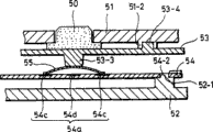
Fig. 1 and Fig. 2 A show the example of the structure of switching device in the mobile telephone unit action button part to 2C, and Fig. 1 shows the push-botton operation part under the assembled state.Fig. 2 A is the figure that push-botton operation part shown in Figure 1 is shown with breakdown to 2C, and wherein Fig. 2 A shows the upper shell that is equipped with button; Fig. 2 B shows the button of arranging and being fixed on the flexure strip; And Fig. 2 C shows the wiring substrate with the contact that is installed on the lower house.In addition, Fig. 3 A and 3B are the figure that the operation of switching device shown in Figure 1 has been described, wherein Fig. 3 A presses button schematic sectional view before; Fig. 3 B presses button schematic sectional view afterwards.
In Fig. 1, be provided with the action button part of a plurality of buttons 50 as mobile telephone unit; On the shell that comprises upper shell 51 and lower house 52, arrange a plurality of switching devices; Upper surface 50-1 (referring to Fig. 2 B) as the button 50 of the operation part that is used for installation switching device exposes from upper shell 51.
Shown in Fig. 2 A, upper shell 51 is made by molded plastics or similar material, and it is equipped with about rectangular aperture 51a, and the upper surface 50-1 of a plurality of buttons 50 can expose by these holes.
This flexure strip 53 is made by mold insulation elastic silicone rubber or similar material, is a kind of thin slice of softness, shown in Fig. 2 B, provide push rod 53-3 on the 53-2 of its back side, ..., button 50 is arranged on the front surface 53-1 of flexure strip 53, and 53a fixes by adhesive.
In this case, the push rod 53-3 at approximate 50-2 center, bottom surface corresponding to button 50 is positioned on the back side 53-2 of flexure strip 53.Further, button 50 is arranged with predetermined space on flexure strip 53 and is fixed, thereby when button is assemblied in the upper shell 51 shown in Fig. 2 A, the sidewall of the top of button 50 and hole 51a can not disturb mutually.
Further, shown in Fig. 2 C, be placed with the wiring substrate 54 that is fixed on lower house 52 1 sides on the back side 53-2 of flexure strip 53 1 sides.This wiring substrate 54 is made of thin printed substrate, flexible circuit board or analog, is providing the contact 54a that is provided with the position corresponding to the push rod 53-3 on the back side 53-2 of flexure strip 53 on the upper surface 54-1.
Shown in sectional view 3A, contact 54a for example is that a plurality of dome element 55 of wherein being made of sheet metal are positioned at the more such contacts in the wiring substrate 54; Annular conductive pad 54c is formed on the upper surface 54-1 of wiring substrate 54, and circular pad 54d is formed on the center of conductive pad 54c, and the rounded periphery of dome element 55 is arranged to effectively to contact the whole circumference of annular conductive pad 54c.Further, thus do not illustrate among the figure on the almost entire upper surface 54-1 of substrate 54 and all be coated with fixedly dome element 55 of dielectric film.
Assembly about the push-botton operation part, along with the flexure strip 53 that is stained with button 50 shown in Fig. 2 B is installed on the lower house that is fixed with wiring substrate 54 52 shown in Fig. 2 C, shown in Fig. 2 A, thereby upper shell 51 exposes button 50 from the top placement from the hole 51a of shell 51; These upper and lower casings 51,52 are all fixed by adhesive, screw and analog.
In this case, as shown in Figure 3A, the wiring substrate 54 that is installed in button 50, the flexure strip 53 between upper shell 51 and the lower house 52 and has a dome element 55 fits together and does not have vertical click.
In addition, in order to make flexure strip 53 and wiring substrate 54 with respect to upper shell in this assembly 51 and lower house 52 or for the operation of button 50, can overlap, flexure strip 53, wiring substrate 54, upper shell 51 and lower house 52 are furnished with outstanding 53-4, hole 54-2, depression 51-2 and projection 52-1 respectively, and outstanding 53-4 and hole 54-2 for example make and mesh with depression 51-2 and projection 52-1 respectively as shown in Figure 3A.
About the operation of the switching device of structure in this way, the state that button 50 shown in Fig. 3 A also is not pressed down becomes the state of the push button 50 shown in Fig. 3 B, when pressing down button 50, flexure strip 53 distortion also are bent downwardly, and the top that push rod 53-3 presses dome element 55 downwards deforms it.Further push the inner surface at dome element 55 tops by circular pad 54d to wiring substrate 54, thereby annular conductive pad 54c and circular pad 54d are electrically connected closing contact, and the finger that is used to operate when dome element 55 deforms can be felt the sensation of card clatter.
Further when having cancelled the power of push button 50, because the restoring force of dome element 55 and flexure strip 53, the state of Fig. 3 B just returns to the reset condition shown in Fig. 3 A.
In addition, as the switching device in this mobile telephone unit, an example is disclosed in the patent documentation 1.
[patent documentation 1] disclosed Japanese patent application 6-309992 number (the 2nd page, Fig. 4)
Summary of the invention
Yet about the switching device shown in the example of Fig. 1 to 3, since button 50 thereby must be fixed on the flexure strip 53 can be to lean against or to install to the mode that the hole of upper shell 51 51a tilts, so when assembling the button part of mobile telephone unit, be difficult to buy individually button 50 and flexure strip 53, they are assembled together mutually; Therefore, usually purchase has been fixed on button 50 on the precalculated position of flexure strip 53.
In other words, in order to realize that button 50 is fixed on assembling on the soft flexure strip 53, must consider because the influence of the performance that the curing condition of adhesive causes, effect etc. flexure strip, and must guarantee the positioning accuracy after the sclerosis, therefore assembling with adhesive needs a large amount of work, and this has just caused the high problem of element unit price.
Further, this switching device is the switch that is used as simple push button in the past independently, is starved of the switch that can utilize simple structure to realize more senior input operation.
The present invention is directed to top understanding and the other problems relevant, and this switch that can utilize simple structure to realize senior input operation is provided with conventional method and equipment.
Switching device according to the embodiment of the present invention or the mobile telephone unit with this switching device comprise button according to push action console switch element, at the shell that presses down the state storage button that is exposed at least on the surface of button, be provided at first localization part placed outside the button be provided at case surface that button contacts on and be positioned at locational second localization part corresponding to first localization part; Wherein intermesh by first and second localization parts and be fixed on the shell in the position of button.
Owing to have a top structure, when downward pressing button from shell expose press down the surface time, first localization part on this button one side descends to second localization part of shell side, its and this first localization part meshes, thereby the console switch element.
Further, further comprise the substrate that is arranged with switch element, be arranged in this suprabasil flexure strip and be arranged in button on this flexure strip according to the above-mentioned switching device of embodiment of the present invention; Wherein be trapped among to press down and be furnished with a plurality of outstanding or conical indentation on the about rectangular direction in surface with it at button outer, with case surface that button contact on be furnished with a plurality of respectively with the conical indentation of the outstanding of button or conical indentation engagement or give prominence to.
Owing to have a this structure, by on the shell side respectively with the button side on the position of outstanding or conical indentation peg button of outstanding or conical indentation engagement, therefore will not be bonded on the flexure strip by button.Further, even since be arranged on shell and the button and button is pressed down after intermeshing conical indentation and give prominence between the interval caused click, button also can return to its home position, in this position, button with respect to the button pressed downwards surface from the hole of the shell that wherein exposes and do not have to be provided with by the center under the situation of click, because when cancelling the power of pressing button, the outstanding restoring force that produces by the elasticity by flexure strip and like on the one side is followed the spacing of the depression on the another side; Therefore allow under heeling condition, to push and control button.
According to the embodiment of the present invention, owing to be provided at first localization part and second localization part engagement that is provided on the shell on the button, make button enter position regulating function with respect to the pre-position of shell so can produce.
In the above-described embodiment, can by disk-shaped button is provided, provide four ends be approximately spherical column outstanding and/or four have that the conical indentation that is approximately 90 ° of spacings with respect to the button center provides four outstanding and/or four depressions simultaneously near the hole of shell and by constructing the multifunction switch device that can operate four switch elements with a button with four switch elements of pitch arrangement of approximate 90 °, wherein each of these four elements all is offset about 45 ° with respect to the center of button away from outstanding or depression.
Further, according to the embodiment of the present invention, position regulating function is provided, button is stored in the shell under the situation that does not produce click by flexure strip, when cancelling the power that button down is pressed, button can return to its home position, do not produce click by the flexure strip button with respect to shell in this position, thereby will not be fixed on the precalculated position of flexure strip by button, and therefore will button and flexure strip stick together, this can reduce production costs.
In the above-described embodiment, can be by disk-shaped button be provided, provide four its ends be approximately spherical column outstanding and/or four have the conical indentation that is approximately 90 ° of spacings with respect to the button center and near the hole of shell, provide four outstanding and/or four depressions simultaneously, and can operate four switch elements and when cancelling the operating physical force of downward pressing button by constructing with four switch elements of pitch arrangement of approximate 90 ° with a button, button can automatically restore to its multifunction switch device that is pressed down reset condition before, and wherein each of these four elements all is offset about 45 ° with respect to the center of button away from outstanding or depression.
The accompanying drawing summary
Fig. 1 is the perspective view of example that the push-botton operation part-structure of switching device in the correlation technique mobile telephone unit is shown;
Fig. 2 A is the perspective view that the element of example formation switching device among Fig. 1 is shown with breakdown to 2C, and wherein Fig. 2 A shows upper shell; Fig. 2 B shows the button that is fixed on the flexure strip; Fig. 2 C shows the wiring substrate with the contact that is fixed on the lower house;
Fig. 3 A and 3B show the sectional view of the example of switching device structure in the correlation technique mobile telephone unit, and wherein Fig. 3 A shows down press operation state before, and Fig. 3 B shows down press operation state afterwards;
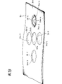
Fig. 4 is the perspective view that illustrates according to the mobile telephone unit outward appearance example of embodiment of the present invention;
Fig. 5 illustrates partial cross section perspective view according to the relevant portion of the structure of embodiment of the present invention in the mode of amplifying and part is analysed and observe;
Fig. 6 is the decomposition diagram according to the relevant portion of the structure of embodiment of the present invention;
Fig. 7 is the sectional view corresponding to I-I line among Fig. 5;
Fig. 8 is according to the perspective view of embodiment of the present invention from the directed load button of its back side displaying;
Fig. 9 is according to the perspective view of embodiment of the present invention from the center button of top displaying;
Figure 10 is from the center button of bottom surface displaying, the perspective view at the back side according to embodiment of the present invention;
Figure 11 illustrates the perspective view that passes through the bore portion on its housing mounted back side according to the directed load button of embodiment of the present invention;
Figure 12 is the perspective view according to the flexure strip of embodiment of the present invention;
Figure 13 is the perspective view that illustrates according to the substrate of embodiment of the present invention;
Figure 14 is the schematic sectional view that is used to illustrate according to the contact structure of embodiment of the present invention;
Figure 15 is the decomposition diagram that is used to illustrate according to the assembling sequence of embodiment of the present invention;
Figure 16 A and 16B are the sectional views that illustrates according to the mode of operation of embodiment of the present invention, and wherein Figure 16 A shows down press operation state before, and Figure 16 B shows down the state after the press operation; And
Figure 17 is the key diagram according to the following press operation engagement state of embodiment of the present invention.
Embodiment
Describe with reference to Fig. 4 to 17 pair of embodiments of the present invention hereinafter.
Fig. 4 is the perspective view that the outward appearance example of mobile telephone unit is shown, and wherein the switching device of present embodiment is provided at the downside of display screen.Fig. 5 amplifies and part illustrates the perspective view of relevant portion of the switching device of present embodiment with the part.Fig. 6 is the decomposition diagram that is used to illustrate the structure of present embodiment switching device.Fig. 7 is the sectional view corresponding to I-I line among Fig. 5.Fig. 8 is a perspective view of showing the directed load button of present embodiment switching device from the back side.Fig. 9 is the perspective view that is contained in the center button the present embodiment switching device from the top presentation group, and Figure 10 is the perspective view of center button inverted and that show from the bottom surface.Figure 11 is the perspective view that the bore portion at the shell back side is shown, and the directed load button of the switching device of present embodiment is installed by these bore portions.Figure 12 is the perspective view of the flexure strip of present embodiment switching device.Figure 13 is the perspective view that the wiring substrate of the contact with present embodiment switching device is shown.Figure 14 is the schematic sectional view that is used to illustrate the contact structure of present embodiment switching device.Figure 15 is the decomposition diagram that is used to illustrate the assembling sequence of present embodiment switching device.The operation that provides Figure 16 A and 16B to be used to illustrate the switching device of present embodiment, wherein Figure 16 A is the schematic sectional view that the state before pressing down is shown, Figure 16 B is the schematic sectional view that the state after pressing down is shown.Figure 17 is the key diagram that the engagement state of switching device when pressing down is shown.
In Fig. 4, the whole mobile telephone unit of reference marker 10 expressions.This mobile telephone unit 10 comprises dialing button partial shell 11 and display part housing 12; Dialing button partial shell 11 has the dialing button 13, microphone 14, the antenna part 15 that are made of a plurality of buttons that are used to import telephone number, character, symbol and similar content, introduces lamp 16, and further comprises the similar portions that does not illustrate among battery, storage card and the figure.In other words, display part housing 12 is equipped with the display 17, the receiver 18 that are made of LCD panel and like, be used to move the cursor that on display 17, shows and similar object directed load button 19, be used for determining the center button 26 of selected item, four specific enter keies 20 or the like that these parts all are stored in the shell that is made of header board 12-1 and backboard 12-3 by cursor.
The example that the switching device of present embodiment is applied to directed load button 19 shown in Figure 4 describes hereinafter.
At first, with reference to Fig. 5 and 6, the structure of the switching device of graphic extension present embodiment.Fig. 5 shows the directed load button 19 and the peripheral region of display 17 belows that are arranged in display part shown in Figure 4 housing (hereafter " housing ") 12 diagonally in the mode of amplifying.As shown in Figure 5, because button-like center button 26 is positioned at the center, and upper surface 19-1 the circular port 12a that provides from housing 12 header board 12-1 (with reference to Fig. 4) is provided exposes, so directed load button 19 is made annular.
Further as shown in Figure 6, directed load button 19 and center button 26 are installed on the flexure strip 23 that is provided in the wiring substrate 24 to cover the zone at 24a place, five contacts, and they also are assemblied in the housing 12 with this state simultaneously.The regional structure at 24a place, five contacts becomes switch element in the wiring substrate 24, and wherein each is all connected by pushing from the top.It should be noted that under this installment state, the push rod 23a-4 of flexure strip 23 is set directly at the orientation mark 21-4 below of directed load button 19, shown in Fig. 7 right-hand side.
Directed load button 19 shown in Figure 6 constitutes by molded plastics; And as shown in Figure 5, be the dish that the center has circular port 19a, this circular port 19a forms the inclined-plane in large quantities in upper surface 19-1 side.Further, shown in Figure 8 as what show from bottom surface 19-2 side, on the bottom surface 19-2 side of the side 19-3 that coils, provide narrow flange portion 19b, provide four protuberances that have about the approximate 90 ° of spacings in center of circular port 19a in the outside of this flange 19b, on the upper surface of these protuberances, provide four its ends and be approximately the spherical outstanding 19c-1 of column to 19c-4.
Shown in Figure 8 further as with inversion mode displayed map 5, concentric and handle from bottom surface 19-2 side greater than the drilling that its ground carries out bore hole in the center of directed load button 19, at circular port 19a with circular port 19a, be provided with level error part 19-4 in the upper surface 19-1 of circular port 19a side.
Further, between the end face 19-3 of the inner circumferential surface 19-7 of circular port 19a and dish, form four grooves, and stay four rib 19d-1 as switch operator to 19d-4.As shown in Figure 8, these ribs 19d-1 is to be offset about 45 ° and setting away from the outstanding 19c-1 of four columns that is positioned on the dish flange 19b to 19c-4 with respect to the center of circular port 19a to 19d-4.
Further shown in Fig. 5 to 7, corresponding to the position of four rib 19d-1 to 19d-4, be embedded with shaft-like orientation mark 21-1 to 21-4 on the upper surface 19-1 of directed load button 19, these signs show the approximate location that directed load button 19 is pressed down significantly.
In addition, as Fig. 9 of showing from the diagonal angle, top and with inversion mode show shown in Figure 10, center button 26 shown in Figure 6 is the button-like parts with plastic moulding, be roughly to be trapezoidal dish simultaneously, on the bottom of the side 26-3 of bottom surface 26-2 (with reference to Figure 10) side, be furnished with flange portion 26a about central shaft cross section shown in Figure 9.Further, its cross section groove 26b of being approximately rectangle is provided to bottom surface 26-2 side shown in Figure 10 and makes annular.In this case, the diameter of center button 26 side 26-3 is made diameter less than the inner circumferential surface 19-6 of directed load button 19 shown in Figure 8, the diameter of the side 26-4 of center button 26 flange portion 26a is made diameter less than the inner circumferential surface 19-7 of directed load button 19 shown in Figure 8.
Shown in Figure 11 as what show from back side 12-2 side, the header board 12-1 of the housing 12 that directed load button 19 exposes that makes shown in Figure 6 is equipped with greater than the external peripheral surface 19-3 (with reference to Fig. 8) of directed load button 19 less than the circular port 12a of flange 19b external diameter.Further, the circular wall part 12b with preset width and height is arranged on around the whole periphery of hole 12a, near four conical indentation 12c-1 are arranged on this wall part 12b to 12c-4.
As shown in figure 11, these conical indentation 12c-1 is integrally formed on the back side 12-2 of header board 12-1 in the wall part 12b outside that has with respect to the about 90 ° of spacings in the center of hole 12a to 12c-4, in other words, after being arranged to contact with the periphery of wall part 12b is approximate, the smooth surface of four cylinders and wall part 12b links together, and handles and forms conical indentation 12c-1 to 12c-4 by carrying out drilling with the conical form that has inclination angle (tapering) at inner circumferential surface at these four cylinders from the top.
In this case, shown in the cross section in the central shaft among Fig. 7 left side, conical indentation 12c-1 to 12c-4 be arranged to make the central shaft of the hole 12a on the housing 12 header board 12-1 and four depression 12c-1 to the central shaft of distance between the central shaft in the hole of 12c-4 and directed load button 19 and four hemispherical outstanding 19c-1 between the central shaft of 19c-4 apart from approximately equal.
As shown in figure 11, be trimmed to the approximately equalised height of upper surface 12-4 that has with wall part 12b to the side of 12c-4 near the conical indentation 12c-1 of cylindrical hole 12a, wall 12d-1 is stayed side away from the hole 12a great distances of cylinder to 12d-4 on.Like this, just the surperficial 19-5 of the flange portion 19b of load button 19 under the surface of the wall part 12b of header board 12-1 back side 12-2 and the above-mentioned top is arranged to adjacent to each otherly, does not break away from a very big scope to the wall 12d-1 on 12c-4 top controls directed load button 19 to 12d-4 outstanding 19c-1 to 19c-4 by conical indentation 12c-1.
Shown in Figure 12 as what show with inversion mode, flexure strip 23 shown in Figure 6 is to be approximately circular, the insulation elastic sheet of moulded silicone rubber or similar substance wherein, thereby its periphery forms the shape of similar skirt to 23-2 rear flank, back side folding, be furnished with push rod 23a-1 to 23a-4 and 23b, on front surface 23-1 side, be wholely set cylinder 23c.
As shown in figure 12, push rod 23b is provided in the approximate center of flexure strip 23 by round bearing, four push rod 23a-1 that are equipped with around this push rod 23b to 23a-4 with about the about 90 ° spacing in the center of push rod 23b (with reference to the cross section shown in the central shaft right side among Fig. 7) thus be arranged on corresponding to four rib 19d-1 of directed load button 19 shown in Figure 8 and it can be pressed to the position of the approximate center of 19d-4.
Further, about being arranged on the cylinder 23c of flexure strip 23 front 23-1 sides, its center is made approximate identical with the center of push rod 23b, thereby determines its internal diameter, external diameter and length that cylinder 23c can be installed among the rectangular channel 26b in the cross section of center button 26 as shown in figure 10 and click does not take place.
Five push rod 23a-1 that determine back side 23-2 top can not cause the yet contact in the inoperation wiring substrate 24 of vertical click (permission) when thereby the height of 23a-4 and 23b makes wiring substrate 24, directed load button 19 and center button 26 when flexure strip 23 and description after a while fit into together to enter state shown in Figure 7 among the header board 12-1 of housing 12.
As shown in figure 14,24a-1 each in 24a-4 and the 24b in contact all is that the dome element 25 that wherein is made of sheet metal is arranged in the wiring substrate 24; Annular conductive pad 24c is formed on the center of conductive pad 24c along with circular pad 24d and is formed on the upper surface 24-1 of wiring substrate 24, and the rounded periphery of dome element 25 is arranged to contact with the whole outer annular conductive pad 24c that places effectively.Further, thus the almost entire upper surface 24-1 of substrate 24 covers fixedly dome element 25 by not shown dielectric film.
Further, make its distortion by the top of pushing dome element 25 downwards, and push the inner surface at top by circular pad 24d to wiring substrate 24, thereby annular conductive pad 24c and circular pad 24d are electrically connected closing contact, in dome element 25 distortion, the finger that is used to operate can be experienced and click thump sensation.It should be noted that what illustrate only is to comprise contact 24a-1 to 24a-4, dome element 25 be arranged in the switch element example of structure of the like in the wiring substrate 24, the switch element with other structures also can replace using.
As shown in figure 15, the switch that at first will construct like this is mounted to the back side 12-2 side that has towards the housing 12 header board 12-1 of last setting; Then four approximate spherical outstanding 19c-1 are installed near be equipped with the hole 12a of header board 12-1 conical indentation 12c-1 in 12c-4 to 19c-4, directed load button 19 is installed simultaneously.
Further, after the flange portion 26a with center button 26 is installed among the level error part 19-4 of directed load button 19 central round orifice 19a, the cylinder 23c on the flexure strip 23 front surface 23-1 is assembled among the groove 26c of center button 26.
Further install is to finish by being placed to by the wiring substrate 24 of not shown method setting from the top to overlap with the backboard 12-3 (with reference to Fig. 5) of display part housing 12; After this, thus total be inverted is obtained the confined state shown in Fig. 5 and 7.
Operation about the switching device of structure like this; Before pressing down directed load button 19 shown in Figure 16 A, infer to load button 19 on 23a-4 and 23b to the bias force of 25-5 (with reference to Figure 13) and the elastic force and the push rod 23a-1 of flexure strip 23 by the dome element 25-1 in the wiring substrate 24, the outstanding 19c-1 of directed load button 19 falls into the conical indentation 12c-1 of housing 12 header board 12-1 back side 12-2 to 12c-4 and therefore definite its position to 19c-4.Notice that Figure 16 A and 16B show I-I cross section among Fig. 5.
Then, when the top of the orientation mark 21-4 as shown in Figure 16 A that pushes directed load button 19 as Figure 16 direction of arrow that B is shown in (with reference to Fig. 5), about the state among directed load button 19 and Figure 16 A relatively, upper surface 19-1 is to pushing the oblique predetermined angle theta of inclination, the height of directed load button 19 δ that descends generally.Like this, along with the flexure strip 23 that is arranged on rib 19d-4 below deforms, by pressing down its push rod 23a-4, pushing dome element 25-4 with push rod 23a-4 deforms, push the inner surface of dome element 25-4 and be electrically connected circular pad 24d-4 and annular conductive pad 24c-4 to the circular pad 24d-4 of wiring substrate 24 one sides, the closing of contact, finger obtains to click thump sensation.
In this case, shown in Figure 16 B, because following press operation, intermesh and therefore near the conical indentation 12c-1 the hole 12a of the display part housing 12 header board 12-1 that locate before the press operation down to the outstanding 19c-1 of 12c-4 and directed load button 19 to just producing a gap between the 19c-4.Especially, the enlarged drawing of D shown in Figure 16 B part shown in Figure 17, because from following press operation by the beginning of the state (state of Figure 16 A) before the following press operation shown in the double dot dash line, directed load button 19 not only vertical moving also moves horizontally (shown in Figure 17 apart from S), and outstanding 19c may break away from conical indentation 12c and can not return to its home position; Yet in the present embodiment,, will can not break away from depression 12c-1 to 12c-4 to 19c-4 outside it so give prominence to 19c-1 because conical indentation 12c-1 is processed to place to 12c-4 and has high wall 12d-1 to 12d-4.
Then, when having discharged operating physical force, owing to the restoring force of dome element 25-1 to 25-4 and flexure strip 23, the state shown in Figure 16 B of press operation just returns to the state shown in Figure 16 A under carrying out.Especially, as shown in figure 17, the approximate bulbous end that is arranged on the outstanding 19c on the directed load button 19 contacts with the conical surface of the depression 12c of housing 12 header board 12-1 back side 12-2 and follows it, the inclination angle of this conical surface is E, directed load button 19 is being provided with by the center on Figure 16 A or its home position shown in double dot dash line among Figure 17 simultaneously, and this position is to press down preoperative predetermined state.
In addition, 12c-1 makes to the inclination angle E of 12c-4 inwall with depression, is 10 to 20 ° with respect to the 12c-1 that caves in to the central shaft in 12c-4 hole for example.
This operation can also be carried out to 21-3 by other orientation marks 21-1 that presses down the directed load button 19 shown in the Figure 4 and 5; The directed load button 19 (pressing down orientation mark 21-1) that can tilt by direction downward in Fig. 4 comes operating contact 24a-1; The directed load button (pressing down orientation mark 21-3) that can tilt by the direction that makes progress in Fig. 4 comes operating contact 24a-3; Can come operating contact 24a-2 by the directed load button (pressing down orientation mark 21-2) that tilts of left direction in Fig. 4.
In addition, for example, if will press down (with reference to Figure 16 A) corresponding to the orientation mark 21-4 of the upper surface 19-1 of the rib 19-4 of directed load button 19, the height of so directed load button 19 δ that just descends generally, its upper surface 19-1 is to being pressed down the aforesaid angle θ of that face tilt; As a result, the push rod 23a-4 that not only is set directly at rib 19-4 below descends but also push rod 23a-1,23a-3 or 23a-2 also descend.Yet these push rods 23a-1 is also not enough so that corresponding dome element 25-1 deforms to 25-3 to the amount that 23a-3 descends, and also be not enough to closing contact, so contact 24a-1 is not operated to 24a-3.
Further shown in Fig. 5 and 16A, although center button 26 and directed load button 19 are arranged on the flexure strip 23 together, but the pliability of flexure strip 23 has still been cut apart the effect of the 19 pairs of center buttons 26 of directed load button that are pressed down, therefore there is not power to be applied on the central contact 24b, equally also owing to the effect of having cut apart the 26 pairs of directed load buttons 19 of center button that are pressed down, so directed load button 19 and center button 26 can apply operation separately individually.
Further, for example can utilize the operation of center button 26 by cursor [determining] menu item [option] of mobile directed load button 19.Further, the switching device of present embodiment can also be as the five contact input switch devices that are made of four contacts by directed load button 19 and a contact by center button 26.
Switching device according to present embodiment, when as an orientation mark 21-1 on the directed load button 19 upper surface 19-1 of button example when the top of 21-4 is pressed down, push rod 23a-1 on flexure strip 23 back side 23-2 in the 23a-4 just optionally goes up four rib 19d-1 that are provided with by back side 19-2 and is pushed to 19d-4, and therefore an annular orientation load button 19 just may operate in suprabasil four contacts pre-fixed contact in addition.
Further, although directed load button 19 is not fixed on the flexure strip 23, even directed load button 19 is pressed down repeatedly and discharges, the position that directed load button 19 returns to can not be moved about the hole 12a on the header board 12-1 yet.Especially, along with cancelling of downforce, directed load button 19 ends are approximately spherical outstanding 19c-1, and the conical indentation 12c-1 on the 12 header board 12-1 moves to the conical surface of 12c-4 inwall to 19c-4 along housing, directed load button 19 can return to its home position placed in the middle simultaneously, so the external peripheral surface 19-3 of the hole 12a of housing 12 and directed load button 19 always can return to the state that has predetermined gap between them.
Further, although be not fixed on the precalculated position of flexure strip 23 as the directed load button 19 of button example, but owing to have a predetermined gap, so when the mutual not bonding and switch that still can obtain to have good function when being installed in the housing 12 of directed load button 19 and flexure strip 23 along with cancelling after the following press operation is total between the hole of housing 12 12a and directed load button 19 with being assembled together.
For this reason, will directed load button 19 and flexure strip 23 bond together, so can reduce the running cost of assembling.
It should be noted, although such example has been described in the present embodiment, promptly, its medial end portions is actual in spherical outstanding 19c is arranged on the one side as the directed load button 19 of switching device action button, conical indentation 12c then be arranged on housing 12 header board 12-1 back side 12-2 hole 12a near; But and be confined to this, outstanding can being arranged on the housing 12, and conical indentation can be arranged on the button side, further needless to say, for example, outstanding and depression can replacedly be arranged on directed load button 19 sides and housing 12 hole 12a near.
Further, although the example of annular four-way load button 19 as the action button of switching device has been described, needless to say, the present invention can be applied to be used to import single load button of assumed name for example, letter and digital character.
Further, an example has been described, that is, wherein four outstanding 19c are arranged to have and are approximately 90 ° cone angle with respect to the center of directed load button 19, and the center that four conical indentation 12c then are arranged to have about the hole 12a of header board 12-1 is approximately 90 ° cone angle; Yet it is opposite with above-mentioned example; Be not limited thereto, because depression and the outstanding binding site that constitutes are provided with so that the button that is pressed down returns to the precalculated position, so when these two binding sites are set, improved horizontal displacement, simultaneously when these three positions are set, improved the inclination of button upper surface when recovering, this means can be according to the form of required button, for example shape, size and press down stroke and decide number by depression and the outstanding binding site that constitutes.
Further, an example has been described, that is, wherein be provided with push rod 23a-1 to the flexure strip 23 of 23a-4 at directed load button 19 be provided with contact 24a-1 between the wiring substrate 24 of 24a-4; Yet for example, if allow directed load button in housing, to send slight click, thus so will unfavorable usefulness has the flexure strip of push rod and operates the suprabasil contact of wiring by directly the contact being pressed down with the outstanding contact-making surface that is arranged on directed load button that is used for push contact.In this case, if will be for example the flexible member of flexible connection board be used for the wiring substrate and the flexure strip setting insulated thereunder in the plane, just may need not distinguishingly carry out mold treatment and construct the switching device that does not have click in mode simply and easily to flexure strip.
Further, although above-mentioned execution mode is an example that has applied the present invention to the mobile telephone unit load button, can also be applied to other electronic equipments of portable electric appts for example or be applied to the action button and the analog of the remote control of electronic equipment.
It will be understood by those skilled in the art in and belong to as carrying out various modifications, combination, recombinant and transformation according to design needs and other factors in the scope of claims or its equivalent.
Claims (6)
1. switching device comprises:
Come the button of console switch element according to following press operation;
The shell that presses down the described button of state storage that is exposed on the surface at button at least;
Be arranged on outer first localization part of placing of described button; And
Second localization part that be arranged on the surface of described shell, contacts with described button in position corresponding to described first localization part;
Wherein, the position of described button is fixed on the described shell by intermeshing described first and second localization parts;
Described switching device also comprises:
Be furnished with the substrate of described switch element on it;
Be arranged in described suprabasil flexure strip; And
Described button arrangement is on described flexure strip;
Wherein, described first localization part is arranged on the outer outstanding or depression of placing of described button, and
Described second localization part is arranged on the locational depression of the outstanding or depression that corresponds respectively to described button or gives prominence to.
2. according to the switching device of claim 1,
Wherein, the depression in described first localization part or described second localization part is a conical indentation.
3. according to the switching device of claim 1 or 2,
Wherein, to be that its end is approximately spherical column outstanding for outstanding in described first localization part or described second localization part.
4. according to the switching device of claim 1 or 2,
Wherein, described button is a plate-like, described first localization part of described button is arranged on four positions, spacing between these four positions is about 90 ° with respect to the center of described button, and described second localization part of described shell also is arranged on four positions with about 90 ° of spacings; And
Described switch element is arranged on described suprabasil four positions, away from each outstanding or about 45 ° of skew of caving in of described button.
5. according to the switching device of claim 3,
Wherein, described button is a plate-like, described first localization part of described button is arranged on four positions, spacing between these four positions is about 90 ° with respect to the center of described button, and described second localization part of described shell also is arranged on four positions with about 90 ° of spacings; And
Described switch element is arranged on described suprabasil four positions, away from each outstanding or about 45 ° of skew of caving in of described button.
6. mobile terminal device that has as each described switching device among the claim 1-5.
Applications Claiming Priority (2)
| Application Number | Priority Date | Filing Date | Title |
|---|---|---|---|
| JP2004181451 | 2004-06-18 | ||
| JP2004181451A JP4417789B2 (en) | 2004-06-18 | 2004-06-18 | Switch device and portable terminal device |
Publications (2)
| Publication Number | Publication Date |
|---|---|
| CN1710681A CN1710681A (en) | 2005-12-21 |
| CN100498998C true CN100498998C (en) | 2009-06-10 |
Family
ID=34937450
Family Applications (1)
| Application Number | Title | Priority Date | Filing Date |
|---|---|---|---|
| CNB2005100781539A Expired - Fee Related CN100498998C (en) | 2004-06-18 | 2005-06-17 | Switching device and portable terminal device |
Country Status (5)
| Country | Link |
|---|---|
| US (1) | US7094979B2 (en) |
| EP (1) | EP1607994A1 (en) |
| JP (1) | JP4417789B2 (en) |
| KR (1) | KR20060049226A (en) |
| CN (1) | CN100498998C (en) |
Families Citing this family (27)
| Publication number | Priority date | Publication date | Assignee | Title |
|---|---|---|---|---|
| JP4279736B2 (en) | 2004-06-25 | 2009-06-17 | ナイルス株式会社 | Switch device |
| US7453446B2 (en) * | 2004-08-20 | 2008-11-18 | Nokia Corporation | Buttons designed for versatile use |
| EP1708216B1 (en) * | 2005-03-31 | 2007-11-21 | TCL & Alcatel Mobile Phones Ltd | Portable communication device with swiveling key |
| TWI269577B (en) * | 2005-08-12 | 2006-12-21 | Asustek Comp Inc | Electronic device |
| CN100456405C (en) * | 2005-08-18 | 2009-01-28 | 华硕电脑股份有限公司 | Electronic equipment |
| US7442886B2 (en) * | 2006-03-07 | 2008-10-28 | Alps Electric Co., Ltd. | Multi-directional input unit |
| CN100561627C (en) * | 2006-03-10 | 2009-11-18 | 鸿富锦精密工业(深圳)有限公司 | Key combination and use its electronic product |
| JP4769603B2 (en) * | 2006-03-16 | 2011-09-07 | アルプス電気株式会社 | Multi-directional input device |
| US7253368B1 (en) * | 2006-03-27 | 2007-08-07 | Zippy Technology Corp. | Pin anchoring structure for button switches |
| KR101176943B1 (en) * | 2006-05-09 | 2012-08-30 | 삼성전자주식회사 | A function key assembly for fortable device |
| JP4605474B2 (en) * | 2006-06-06 | 2011-01-05 | サンアロー株式会社 | Multi-directional input device |
| US7427725B2 (en) * | 2006-08-25 | 2008-09-23 | Darfon Electronics Corp. | Keyboards |
| US20080068339A1 (en) * | 2006-09-18 | 2008-03-20 | Henrik Jensfelt | Electronic device with keypad assembly |
| WO2008044764A1 (en) * | 2006-10-12 | 2008-04-17 | Nec Corporation | Operation key structure |
| WO2008147266A1 (en) * | 2007-05-30 | 2008-12-04 | Neonode Ab | Multi-function input device |
| CN101364490B (en) * | 2007-08-06 | 2013-02-20 | 鸿富锦精密工业(深圳)有限公司 | Dual-color forming press key and manufacturing method therefor |
| US20090045986A1 (en) * | 2007-08-14 | 2009-02-19 | Sony Ericsson Mobile Communications Ab | Illuminated keyboard and light guide for graphic symbols and method |
| KR100836628B1 (en) * | 2007-09-20 | 2008-06-10 | 삼성전기주식회사 | Rotational inputting apparatus |
| US8129645B2 (en) * | 2007-11-13 | 2012-03-06 | Quadtri Technologies, Llc | Dynamically self-stabilizing elastic keyswitch |
| US20100102996A1 (en) * | 2008-10-23 | 2010-04-29 | Yui-Chen Huang | Dome array device and a key structure with the dome array device |
| US8445795B2 (en) * | 2010-10-12 | 2013-05-21 | Cisco Technology, Inc. | Multi function navigational switch |
| JP6009908B2 (en) * | 2012-10-31 | 2016-10-19 | 株式会社ヴァレオジャパン | Multi-directional switch |
| JP6349631B2 (en) * | 2013-06-21 | 2018-07-04 | 株式会社リコー | Switch mechanism and electronic device |
| TWI496030B (en) * | 2013-07-10 | 2015-08-11 | Ichia Tech Inc | Thin key structure |
| US9552939B2 (en) * | 2014-09-15 | 2017-01-24 | Zippy Technology Corp. | Keyboard equipped with multipoint press positions |
| JP2016066543A (en) * | 2014-09-25 | 2016-04-28 | ブラザー工業株式会社 | Multidirectional switch |
| JP6567019B2 (en) * | 2017-11-14 | 2019-08-28 | ホーチキ株式会社 | Transmitter and mounting method of transmitter |
Citations (5)
| Publication number | Priority date | Publication date | Assignee | Title |
|---|---|---|---|---|
| US3483337A (en) * | 1967-01-06 | 1969-12-09 | Gen Motors Corp | Six-way rotary inclined plane centering switch |
| US5086313A (en) * | 1988-01-28 | 1992-02-04 | Asahi Kogaku Kogyo Kabushiki Kaisha | Operation switch unit for a camera |
| US5525770A (en) * | 1992-07-31 | 1996-06-11 | Sega Enterprises, Ltd. | Control-key mechanism having improved operation feeling |
| US6246019B1 (en) * | 1999-03-15 | 2001-06-12 | Matsushita Electric Industrial Co., Ltd. | Multidirectional switch and complex type switch using the same |
| US6593909B1 (en) * | 2000-06-29 | 2003-07-15 | Shin Jiuh Corp. | Direction-control switch module for controlling a screen cursor |
Family Cites Families (10)
| Publication number | Priority date | Publication date | Assignee | Title |
|---|---|---|---|---|
| US3691324A (en) * | 1971-04-28 | 1972-09-12 | Brin Mfg Co Inc | Multiple circuit switch with pivoted contact only one switch operable at a time |
| US4582967A (en) * | 1984-10-22 | 1986-04-15 | Tec, Inc. | Key switch assembly |
| US4786766A (en) | 1985-08-26 | 1988-11-22 | Canon Kabushiki Kaisha | Keyboard apparatus |
| JP2695682B2 (en) * | 1990-07-10 | 1998-01-14 | 三菱電機株式会社 | Push button mechanism |
| JPH06309992A (en) | 1993-04-26 | 1994-11-04 | Hitachi Ltd | Key pad |
| JPH11329161A (en) * | 1998-05-20 | 1999-11-30 | Sega Enterp Ltd | Control key device |
| JP2003059368A (en) * | 2001-08-22 | 2003-02-28 | Mitsumi Electric Co Ltd | Key switch |
| US6670563B1 (en) * | 2002-12-03 | 2003-12-30 | Samsung Electronics Co., Ltd. | Rotation key device for a portable terminal |
| US6961052B1 (en) * | 2003-03-17 | 2005-11-01 | Cisco Technology, Inc. | Methods and apparatus for providing multi-directional navigation control |
| JP2004281291A (en) * | 2003-03-18 | 2004-10-07 | Matsushita Electric Ind Co Ltd | Electronic equipment and pushing button used for the same |
-
2004
- 2004-06-18 JP JP2004181451A patent/JP4417789B2/en not_active Expired - Fee Related
-
2005
- 2005-06-08 US US11/147,330 patent/US7094979B2/en not_active Expired - Fee Related
- 2005-06-14 EP EP05012805A patent/EP1607994A1/en not_active Ceased
- 2005-06-16 KR KR1020050051900A patent/KR20060049226A/en active IP Right Grant
- 2005-06-17 CN CNB2005100781539A patent/CN100498998C/en not_active Expired - Fee Related
Patent Citations (5)
| Publication number | Priority date | Publication date | Assignee | Title |
|---|---|---|---|---|
| US3483337A (en) * | 1967-01-06 | 1969-12-09 | Gen Motors Corp | Six-way rotary inclined plane centering switch |
| US5086313A (en) * | 1988-01-28 | 1992-02-04 | Asahi Kogaku Kogyo Kabushiki Kaisha | Operation switch unit for a camera |
| US5525770A (en) * | 1992-07-31 | 1996-06-11 | Sega Enterprises, Ltd. | Control-key mechanism having improved operation feeling |
| US6246019B1 (en) * | 1999-03-15 | 2001-06-12 | Matsushita Electric Industrial Co., Ltd. | Multidirectional switch and complex type switch using the same |
| US6593909B1 (en) * | 2000-06-29 | 2003-07-15 | Shin Jiuh Corp. | Direction-control switch module for controlling a screen cursor |
Also Published As
| Publication number | Publication date |
|---|---|
| EP1607994A1 (en) | 2005-12-21 |
| JP2006004830A (en) | 2006-01-05 |
| US20050279619A1 (en) | 2005-12-22 |
| CN1710681A (en) | 2005-12-21 |
| US7094979B2 (en) | 2006-08-22 |
| KR20060049226A (en) | 2006-05-18 |
| JP4417789B2 (en) | 2010-02-17 |
Similar Documents
| Publication | Publication Date | Title |
|---|---|---|
| CN100498998C (en) | Switching device and portable terminal device | |
| JP4899963B2 (en) | Input device and manufacturing method thereof | |
| US7230197B2 (en) | Movable contact, moveable contact unit including the same, and switch including the same movable contact | |
| CN101238532B (en) | Button input apparatus with display function and portable electronic device having the same | |
| US20080309638A1 (en) | Input device and method of manufacturing module unit for input device | |
| CN101599380B (en) | Key structure and electronic equipment with same | |
| CN102221915B (en) | Movable touch module and electronic device using same | |
| JP4799655B2 (en) | Small equipment | |
| GB2253586A (en) | Key pad method of manufacture | |
| US7053885B2 (en) | Multi-directional input key and key input device | |
| RU2635872C2 (en) | Housing formed by two-component injection moulding, with seats for key caps in user interface | |
| KR20010086074A (en) | 5-Directional key operation device | |
| KR20100088832A (en) | The method and device of input for portable terminal | |
| CA2921417C (en) | Double pre-loaded deflection webs for keypad | |
| US7301114B2 (en) | Movable contact unit | |
| CA2921471C (en) | Double pre-loaded deflection webs for keypad | |
| US7663070B2 (en) | Four-way rocker switch with display | |
| JP4071579B2 (en) | KEY SWITCH DEVICE, AND MOBILE TELEPHONE DEVICE AND ELECTRONIC DEVICE HAVING THE SAME | |
| JP2013125671A (en) | Sheet with movable contact | |
| EP1492137B1 (en) | Switch dome device | |
| US20110187575A1 (en) | Remote control transmitter | |
| KR200325977Y1 (en) | telephone-system having a navigation key buttom | |
| JP2014071791A (en) | Touch panel and input device using the same | |
| CN101860585B (en) | Mobile electronic device and key structure thereof | |
| JP4837143B1 (en) | Broadcast receiving system and electronic device |
Legal Events
| Date | Code | Title | Description |
|---|---|---|---|
| C06 | Publication | ||
| PB01 | Publication | ||
| C10 | Entry into substantive examination | ||
| SE01 | Entry into force of request for substantive examination | ||
| C14 | Grant of patent or utility model | ||
| GR01 | Patent grant | ||
| CF01 | Termination of patent right due to non-payment of annual fee | ||
| CF01 | Termination of patent right due to non-payment of annual fee |
Granted publication date: 20090610 Termination date: 20160617 |