CN100522064C - System and method for scanning an object in tomosynthesis applications - Google Patents
System and method for scanning an object in tomosynthesis applications Download PDFInfo
- Publication number
- CN100522064C CN100522064C CNB2004100620119A CN200410062011A CN100522064C CN 100522064 C CN100522064 C CN 100522064C CN B2004100620119 A CNB2004100620119 A CN B2004100620119A CN 200410062011 A CN200410062011 A CN 200410062011A CN 100522064 C CN100522064 C CN 100522064C
- Authority
- CN
- China
- Prior art keywords
- detector
- positions
- scanning
- axon
- zone
- Prior art date
- Legal status (The legal status is an assumption and is not a legal conclusion. Google has not performed a legal analysis and makes no representation as to the accuracy of the status listed.)
- Active
Links
Images


Classifications
-
- A—HUMAN NECESSITIES
- A61—MEDICAL OR VETERINARY SCIENCE; HYGIENE
- A61B—DIAGNOSIS; SURGERY; IDENTIFICATION
- A61B6/00—Apparatus for radiation diagnosis, e.g. combined with radiation therapy equipment
- A61B6/02—Devices for diagnosis sequentially in different planes; Stereoscopic radiation diagnosis
- A61B6/025—Tomosynthesis
-
- G—PHYSICS
- G01—MEASURING; TESTING
- G01N—INVESTIGATING OR ANALYSING MATERIALS BY DETERMINING THEIR CHEMICAL OR PHYSICAL PROPERTIES
- G01N23/00—Investigating or analysing materials by the use of wave or particle radiation, e.g. X-rays or neutrons, not covered by groups G01N3/00 – G01N17/00, G01N21/00 or G01N22/00
- G01N23/02—Investigating or analysing materials by the use of wave or particle radiation, e.g. X-rays or neutrons, not covered by groups G01N3/00 – G01N17/00, G01N21/00 or G01N22/00 by transmitting the radiation through the material
- G01N23/04—Investigating or analysing materials by the use of wave or particle radiation, e.g. X-rays or neutrons, not covered by groups G01N3/00 – G01N17/00, G01N21/00 or G01N22/00 by transmitting the radiation through the material and forming images of the material
- G01N23/044—Investigating or analysing materials by the use of wave or particle radiation, e.g. X-rays or neutrons, not covered by groups G01N3/00 – G01N17/00, G01N21/00 or G01N22/00 by transmitting the radiation through the material and forming images of the material using laminography or tomosynthesis
-
- G—PHYSICS
- G01—MEASURING; TESTING
- G01N—INVESTIGATING OR ANALYSING MATERIALS BY DETERMINING THEIR CHEMICAL OR PHYSICAL PROPERTIES
- G01N23/00—Investigating or analysing materials by the use of wave or particle radiation, e.g. X-rays or neutrons, not covered by groups G01N3/00 – G01N17/00, G01N21/00 or G01N22/00
- G01N23/02—Investigating or analysing materials by the use of wave or particle radiation, e.g. X-rays or neutrons, not covered by groups G01N3/00 – G01N17/00, G01N21/00 or G01N22/00 by transmitting the radiation through the material
- G01N23/04—Investigating or analysing materials by the use of wave or particle radiation, e.g. X-rays or neutrons, not covered by groups G01N3/00 – G01N17/00, G01N21/00 or G01N22/00 by transmitting the radiation through the material and forming images of the material
- G01N23/046—Investigating or analysing materials by the use of wave or particle radiation, e.g. X-rays or neutrons, not covered by groups G01N3/00 – G01N17/00, G01N21/00 or G01N22/00 by transmitting the radiation through the material and forming images of the material using tomography, e.g. computed tomography [CT]
-
- A—HUMAN NECESSITIES
- A61—MEDICAL OR VETERINARY SCIENCE; HYGIENE
- A61B—DIAGNOSIS; SURGERY; IDENTIFICATION
- A61B6/00—Apparatus for radiation diagnosis, e.g. combined with radiation therapy equipment
- A61B6/02—Devices for diagnosis sequentially in different planes; Stereoscopic radiation diagnosis
- A61B6/027—Devices for diagnosis sequentially in different planes; Stereoscopic radiation diagnosis characterised by the use of a particular data acquisition trajectory, e.g. helical or spiral
-
- G—PHYSICS
- G01—MEASURING; TESTING
- G01N—INVESTIGATING OR ANALYSING MATERIALS BY DETERMINING THEIR CHEMICAL OR PHYSICAL PROPERTIES
- G01N2223/00—Investigating materials by wave or particle radiation
- G01N2223/40—Imaging
- G01N2223/419—Imaging computed tomograph
-
- G—PHYSICS
- G01—MEASURING; TESTING
- G01N—INVESTIGATING OR ANALYSING MATERIALS BY DETERMINING THEIR CHEMICAL OR PHYSICAL PROPERTIES
- G01N2223/00—Investigating materials by wave or particle radiation
- G01N2223/60—Specific applications or type of materials
- G01N2223/612—Specific applications or type of materials biological material
Abstract
A tomosynthesis system for scanning a region in an object comprises a radiation source configured to traverse in a plurality of positions yielding a plurality of scanning directions. Each of the plurality of positions corresponds to a respective scanning direction. Further, the plurality of scanning directions comprise at least a scanning direction along a first axis and a direction along a second axis, the second axis being transverse to the first axis.
Description
Technical field
The present invention relates generally to imaging field, more specifically relate to synthetic (tomosynthesis) field of tomography.Particularly, the present invention relates to digital tomosynthesis system and method, its image acquisition point that adopts the new track while scan that is used for x-ray source and be used for detector with obtain object through improved image.
Background technology
Tomography all is well-known for industry and medical application.Conventional tomography is based on the relative motion of x-ray source, detector and object.Typically, x-ray source and detector on circle with moved further or translation in an opposite direction simply.Because this relevant motion, also move the position of the projected image of the point in the object.Only, typically be called as the focus lamella, will always be projected on the detector and therefore clearly imaging of quilt in identical position from the point of specific lamella.The focus lamella is above will for good and all to be projected in the diverse location place with following object structure.Therefore, they not by imaging sharply and will be as a setting intensity and being applied to the focus lamella.It is synthetic that this principle of using the projection of discrete number to produce the 3D rendering of a lamella (focus lamella) that has in focus is called as tomography.
The digital tomosynthesis system that is used for medical application typically uses such x-ray source, and it is used to produce fan-shaped or the cone type X-ray bundle, and this bundle is collimated and detected by one group of detector element then through patient.Detector element is based on the decay of X-ray beam and produce signal.This signal can be processed to produce the radiography projection.Described source, patient or detector typically relative to each other move so that ensuing exposure is gathered thereby make each be projected in the different angles place by mobile x-ray source then.
By using reconfiguration technique, as the back projection through filtering, the projection group of being gathered can be gone up useful 3-D view to produce diagnosis by reconstruct then.Because three-dimensional information is obtained on the numeral between synthesis stage at tomography, image can be by reconstruct in any viewing plane that the operator selects.Typically, expression treats that the lamella group of certain volume of interest of object of imaging is by reconstruct, wherein each lamella all is the image through reconstruct of the structure in the expression plane parallel with detector plane, and each lamella is all corresponding to the different distance of described plane and detector plane.
In addition, come the reconstruct three-dimensional data from projection, compare with using single X ray radiography because tomography is synthetic, it provide a kind of fast and the cost otherwise effective technique be used for removing synergetic anatomical structure and be used to strengthen the contrast on plane in focus.In addition, because being taken a picture by few relatively projection ray of gathering rapidly in single the sweeping (sweep) of common x-ray source on patient, the tomography generated data forms, by the total x-ray dose of patient's reception and the dosage of single conventional X ray exposure is suitable, and typically is significantly less than the dosage that receives from CT (CT) inspection.In addition, the resolution of the synthetic middle detector that adopts of tomography is typically greater than the resolution of the detector that uses in CT examination.These qualities make tomography synthetic for being useful such as detecting the nodular radiology task of lung or pathological other difficult problem of imaging.
Although synthetic these significant benefits that provides of tomography, the technology synthetic related with tomography also has shortcoming.
Usually demonstrate the fuzzy of structure on the direction of the projection that is being used to gather the tomography generated data through the data set of reconstruct during tomography is synthetic.This is to blur with the depth resolution of the difference of 3D reconstruct or the degree of depth to represent.These illusions related with imaging arrangement will change according to the structural approach with respect to acquisition geometry.For example, will on the entire depth of volume of interest, seem fuzzy with the aligned linear structure of the linear movement of linear x-ray tomography synthesis system.And that this structure will be blured fewly by the circus movement of circular x-ray tomography synthesis system will be many.In reconstituting the picture process of volume, the fuzzy separation that can produce unfavorable image artifacts and suppress to be positioned at the structure at differing heights place of structure.
Therefore, needing to change current digital tomosynthesis system blurs with the degree of depth that solves imaging object so that new track while scan and image acquisition point to be provided.
Summary of the invention
The digital tomosynthesis system that is used for the zone of sweep object comprises radiation source, and it is configured to pass (traverse) a plurality of positions to obtain a plurality of scanning directions.Each of described a plurality of positions is corresponding to corresponding scanning direction.In addition, described a plurality of scanning directions comprise at least along first scanning direction with along second direction, described second transverse to described first.
The method that is used for using digital tomosynthesis system to come the zone of sweep object comprises along first and along the zone in second sweep object, described second transverse to described first.In addition, described scanning comprises crosses a plurality of positions with radiation source, and each of described a plurality of positions is corresponding to corresponding scanning direction.Described method also comprises by use and is placed on a plurality of projected images that come the zone in the acquisition target with the detector at the preset distance place of object.
Description of drawings
Based on detailed description below reading and with reference to accompanying drawing, above and other advantage of the present invention and characteristics will become apparent, in the accompanying drawings:
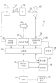
Fig. 1 is the sketch map of the example imaging system of the digital tomosynthesis system form that is used for sweep object of the aspect according to present technique;
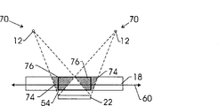
Fig. 2 is the sketch map of physical implementation of the digital tomosynthesis system of Fig. 1;
Fig. 3 is the top view of conventional digital tomosynthesis system and related question wherein;
Fig. 4 is the top view of embodiment that solves the present technique of problem illustrated in fig. 3;
Fig. 5 is the top view of another embodiment of present technique, and it has illustrated along patient's major axis and moving transverse to the x-ray source of major axis;
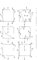
Fig. 6 is the set according to the top view of a plurality of scanning directions of the x-ray source of the aspect of present technique; And
Fig. 7 is the set by the top view of the collection point of detector according to the aspect of present technique.
The specific embodiment
Fig. 1 schematically illustrates and can be used to gather the also imaging system 10 of image data processing.In the illustrated embodiment, system 10 is digital tomosynthesis systems, and it is designed to gather raw image data and image data processing so that show and analyze according to present technique.In embodiment illustrated in fig. 1, imaging system 10 comprises radiation source 12, and described radiation is the X-radiation of tomography in synthetic typically, and source 12 planar can move freely usually.In this example embodiment, x-ray radiation source 12 typically comprises X-ray tube and related support and filter element.
In embodiment illustrated in fig. 1, system controller 24 is coupled in location subsystem 26, and it is with respect to object 18 and detector 22 and location x-ray source 12.In interchangeable embodiment, location subsystem 26 removable detectors 22 or even object 18 rather than source 12 or mobile with source 12.In yet another embodiment, by the control of location subsystem 26, be movably more than one parts.Like this, according to each embodiment of following detailed description, by the relative position by location subsystem 26 change sources 12, object 18 and detector 22, the radiography projection can be obtained in all angles by object 18.
In addition, as skilled in the art will appreciate, radiation source can be controlled by the X ray controller 30 that is placed in the system controller 24.Particularly, X ray controller 30 is configured to provide power and clock signal to x-ray source 12.Motor controller 32 is used to moving of control position subsystem 26.
In addition, system controller 24 also is illustrated and comprises data collecting system 34.Detector 22 typically is coupled in system controller 24, more specifically is data collecting system 34.Data collecting system 34 receives the data that electronic device is collected of reading by detector 22.Data collecting system 34 typically receives comes the analogue signal through sampling of self-detector 22 also this data transaction to be become digital signal so that handled by computer 36 subsequently.
The display 42 that is coupled in operator's work station 40 can be used to observe through the image of reconstruct and be controlled to picture.In addition, image also can be printed on the printer 44, and this printer can be coupled in computer 36 and operator's work station 40.In addition, operator's work station 40 also can be coupled in picture filing and communication system (PACS) 46.Should point out that PASC 46 can be coupled in long range systems 48, radiology information system (RIS), hospital information system (HIS), perhaps inside or external network, thereby make the diverse location place other people can obtain to image with to the visit of view data.
Be further noted that computer 36 and operator's work station 46 can be coupled in other outut device, these equipment can comprise standard or special-purpose computer monitor and association process circuit.One or more operator's work stations 40 can further be linked in the system so that image etc. is checked, watched to output system parameter, request.Generally speaking, the display that provides in system, printer, work station and similar devices can be local for the data acquisition parts, can be remote perhaps with these parts, as other place in mechanism or hospital, perhaps in diverse position, by one and a plurality of configurable networks, be linked in image capturing system as the Internet, virtual private net (virtualprivate network) etc.
Briefly with reference to figure 2, the example imaging system of Li Yonging can be a tomosynthesis imaging system 50 in the present embodiment.In being similar to above-described arrangement, tomosynthesis imaging system 50 is shown having source 12 and detector 22, can place the object that is shown as patient 18 therebetween.Radiation source 12 typically comprises X-ray tube, and its emission is from the X-radiation of focus 52.Radiant flux is directed to patient 18 specific region 54.Should point out, thereby the most useful scanning to the zone is typically selected to carry out by the operator in patient 18 specific region 54.
In typical operation, x-ray source 12 be placed in patient more than 18 the preset distance place and from focus 52 with the X-ray beam projection to detector array 22.Detector 22 be placed be in with respect to the spaced apart relation in source 12 and be in preset distance place with patient 18.Detector 22 is formed by a plurality of detector element corresponding to pixel usually usually, and described detector element sensing passes through and walks around object of interest 54, as the given body part, and the X ray of chest, lung etc. for example.In one embodiment, detector 22 is made up of 2,048 x, 2,048 rectangular arrays of element, and it is corresponding to the Pixel Dimensions of 200 μ m x, 200 μ m, although other configuration of detector 22 and pixel and size are possible certainly.The signal of telecommunication of the intensity of the X-ray beam at this position of components place when each detector element produces the described bundle shock detector of expression.In addition, source 12 can be displaced in first plane 56 usually, and it is arranged essentially parallel to second plane 58, and it is the plane of detector 22, therefore watches and can be collected by computer 36 from a plurality of radiographies of different visual angles.X-ray source move following with reference to Fig. 4 discussion and described in detail.In one embodiment, the distance between source 12 and the detector 22 is approximately 180cm, and the total size of the motion in source 12 is between 13.5cm and 131cm, and it changes into from ± 5 ° to ± 20 °, and wherein 0 ° is the center.In this embodiment, typically at least 11 projections are gathered, thereby have covered the full angle scope.
At x-ray source 12 usually in plane 56 when mobile, the X-ray beam data that detector 22 is collected through decay.The data of collecting from detector 22 typically experience pretreatment and the line integral of calibrating with the attenuation quotient that data is adjusted to the expression sweep object then.The treated data that are commonly referred to as projection are then typically by the image of back projection with the planning scanning area.In tomography was synthetic, the projection of limited quantity was gathered, typically 30 or below, each all is in the different angles place with respect to object and detector.Restructing algorithm typically is used to carry out reconstruct to these data to reproduce initial pictures.
In case by reconstruct, the image that the system of Fig. 1 and 2 produces has disclosed the three-dimensional relationship of patient 18 internal feature.Image can be shown so that these features and three-dimensional relationship thereof to be shown.Although the image through reconstruct can comprise the single lamella through reconstruct that is expressed as the structure of corresponding position in the picture volume, is typical more than a lamella.
With reference now to Fig. 3,, it has illustrated the top view of typical linear tomographic synthesis system and related with it problem.Typically, source 12 the plane neutral line of patient more than 18 move with to regional 54 imagings, projected image is caught by fixed detector 22.Move along first 60 in source 12, and this is long axon of the patient 18, and between this moving period, and it is to by the external regional imaging of reference number 74 general description and do not comprise a part by the zone 54 of reference number 76 general description.Like this, in these conventional systems, from the data of (above and following) beyond the zone 54 will be comprised in the projection and so be comprised in the reconstruct, thereby be injected in the reconstruct problem irrationality and the picture quality of demoting.
Fig. 4 has illustrated the different embodiment that solve the problem of describing among Fig. 3 with Fig. 5.With reference to figure 4, it has illustrated the top of view of the digital tomosynthesis system 50 in the zone 54 that is used for scanning patient 18.System 50 comprises radiation source 12, and it is configured to cross a plurality of positions 70, thereby obtains a plurality of scanning directions 72.In this configuration, each of described a plurality of positions is corresponding to corresponding scanning direction.In example embodiment, at least one of described a plurality of positions 70 limited by the edge 64 along the detector 22 on the direction of first 60 promptly long axon.In this configuration, because x-ray source 12 moves to the edge 64 of detector 22 always, it has overcome the problem shown in Fig. 3: comprise external zone in scanning process, i.e. the tissue of overlapping region 54.In another example embodiment, at least two two edges 64 by detector 22 of described a plurality of positions 70 limit.
In addition, in another example embodiment as shown in Figure 5, described a plurality of scanning directions comprise at least along first 60 promptly long axon the scanning direction and along the second 62 i.e. direction of short axon, described second horizontal described first.In the case, owing on the scanning direction, there is not bodily tissue to exceed (beyond) detector, eliminated fully from the problem of the tissue beyond the region-of-interest.Like this, scan on the long axis of body direction of describing by reference number 60 detector edge and on the vertical direction of describing by reference number 62 than the long scan path on the two-dimensional scan configuration that scans realized the sharp keen resolution on the z direction and eliminated benefit from the problem of the overlapping tissue beyond the region-of-interest.Described embodiment with the region-of-interest 54 of useful examples in the patient 18 in one direction (for example along axle 60) extend beyond detector 22.
The source with 180cm to detector distance, scanning be arranged in the valid detector surface before 7cm 25cm thickness and with the digital tomosynthesis system of the object of detector (41cm x 41cm) same lateral yardstick, because object is the same with detector wide, and X-ray beam is the cone beam of dispersing from focus, for the only scanning of the long axon in edge (axle 60) in conventional digital tomosynthesis system, lateral approximate 11% the zone of object is uncovered in the projection of any X ray.By using above-described embodiment, the scanning that comprises the point on horizontal (lateral) direction at detector edge place has guaranteed that each image-forming component in the reconstruct comprises from the information of at least one X-ray measurement and therefore obtains image than good quality.
As the skilled person will understand, above embodiment experiences several useful scannings configurations and relevant collection by detector 22.At this, with reference to Fig. 6 and Fig. 7 and come into question, several other configurations are possible to these illustrated unrestricted examples following.
Fig. 6 has illustrated the example collection by the scanning of reference number 86,88,90,92,94 and 96 general description configuration that is used for above-described various embodiment.In an example, described a plurality of scanning direction 72 comprises a plurality of areas that covering is limited by a plurality of pre-dimensioning of detector 22 respectively.In example embodiment, described a plurality of pre-dimensionings comprise the width 66 and the height 68 of detector 22 at least.In another example, described a plurality of area comprises at least width 66 and height 68 areas that limit by detector 22.In another example, described a plurality of areas comprise at least by the part of the height of the width of detector and detector and the area that limits.Another example comprises at least by the part of the width of the height of detector and detector and the area that limits.Another example comprises at least by the multiple of the height of the width of detector and detector and the area that limits.Another example comprises at least by the multiple of the width of the height of detector and detector and the area that limits.Another example comprises at least the area that is limited by the part of the part of the width of detector and height.
Fig. 7 has illustrated the example collection of collection by a plurality of collection points 78 at detector 22 places of a plurality of projected images of reference number 98,100,102,104,106 and 108 general description.In an example, described a plurality of predetermined collection point comprises at least two points 78 at two relative angle 80 places of detector 22.In another example, described a plurality of predetermined collection point 78 comprises the point at 82 places, center of at least two points 78 at two relative angle 80 places of detector and detector 22.In another example, described a plurality of predetermined collection points comprise at least four points 78 at 80 places, four angles of detector 22.Another example comprises the point at 82 places, center of at least four points 78 at four relative angle 80 places of detector and detector 22.Another example comprises the point at 82 places, center of the central point at least 84 at each edge of detector and detector 22.Another example comprises the central point at least 84 at each edge of detector 22.Another example comprise along the detector border at least more than four point.Another example comprises at least the point by the edge limited variation distance of the center 82 of detector and detector.In another example, described a plurality of predetermined collection point 78 comprises a plurality of at least points beyond the detector 22, wherein beyond the detector described a plurality of corresponding to the edge with second scanning direction of first of patient 18 horizontal direction during radiation source positions 70.
Another example embodiment (not shown) comprises detector 22, and it is configured to cross (traverse) on a plurality of directions in plane 58, and each of described a plurality of directions corresponds respectively to each of described a plurality of positions 70 of radiation source 12.As the skilled person will understand, above-described scanning configuration and collection can be applicable to this embodiment with being equal to, and wherein detector is configured to move.
Another aspect of described technology is the method in the zone 54 that is used for using digital tomosynthesis system 50 to come sweep object 18.This method comprises along first 60 and along the zone 54 in second 62 sweep object 18, described second transverse to described first.Described scanning comprises further that with radiation source 12 traversing a plurality of positions 70 each of described a plurality of positions is corresponding to corresponding scanning direction 72; And be placed on a plurality of projected images that come the zone in the acquisition target with the detector 22 at the preset distance place of object by use.
Another aspect of above method comprises by use and is placed on a plurality of projected images that come the zone 54 in the acquisition target 18 with the detector 22 at the preset distance place of object.In aspect this, at least one of described a plurality of positions limited by the edge along the detector on first 60 the direction.
As the skilled person will understand, described technology also comprises and is used to use above-described each embodiment of the present invention to scan method with images acquired.
As the skilled person will understand, above embodiment also is useful in other imaging form, and these unrestricted example comprises stereotaxis (stereotaxy), three-dimensional imaging, for example in the mammography imaging system.In addition, except useful in medical imaging, above embodiment also is useful in industrial imaging, for example in the process of the weld seam in check such as flat component of multilayer board or big parts.
Although various modifications of tolerable of the present invention and replaceable form illustrate by the example in the accompanying drawing and at this in detail certain embodiments have been described in detail.However, it should be understood that the present invention is not intended to be limited to particular forms disclosed, on the contrary, the present invention should cover all modifications, equivalents and the replaceable form that belongs in the spirit and scope of the present invention that limit as following claims.
Component List
10 imaging systems
12 radiation sources
14 collimaters
The X-ray beam of 16 irradiation objects
18 objects
20 X-ray beams by the object decay
22 detectors
24 system controllers
30 X ray controllers
32 motor controllers
34 data collecting systems
36 computers
38 memorizeies
40 operator's work stations
42 display
44 printers
46?PACS
48 remote clients
50 digital tomosynthesis systems
52 x-ray source focuses
54 zones
56 first planes
58 second planes
60 first
62 second
The edge of 64 detectors
The width of 66 detectors
The height of 68 detectors
A plurality of positions of 70 x-ray sources
More than 72 scanning direction
Additional areas on 74 anatomy
76 from zone that anatomy is missed
More than 78 collection point
The angle of 80 detectors
The center of 82 detectors
Intermediate point on the 84 detector sides
Many scanning directions of 86-96
Many collection points of 98-108
Claims (10)
1. digital tomosynthesis system (50) that is used for the zone (54) of sweep object (18), this system comprises:
Radiation source (12), it is configured to cross a plurality of positions (70) to obtain a plurality of scanning directions (72), each of wherein said a plurality of positions is corresponding to corresponding scanning direction, and wherein said a plurality of scanning direction comprises that at least described short axon is transverse to described long axon along the direction of the scanning direction of long axon (60) and the short axon in edge (62).
2. the system of claim 1, further comprise detector (22), it is configured to from by object attenuated radiation bundle (20) and a plurality of projected images in zone (54) the acquisition target (18), and wherein detector is placed and is in respect to the spaced apart relation of source (12) and is in preset distance place with object.
3. the system of claim 2, at least one of wherein said a plurality of positions (70) limited by the edge (64) along the detector (22) on the direction of long axon (60).
4. the system of claim 2, at least two two edges (64) by detector (22) of wherein said a plurality of positions (70) limit.
5. the system of claim 2, wherein the zone (54) in the object (18) extends beyond detector (22).
6. the system of claim 2, wherein said a plurality of scanning directions (72) comprise a plurality of zones that covering is limited by a plurality of pre-dimensioning of detector (22), wherein said a plurality of pre-dimensionings comprise the height (68) and the width (66) of detector at least.
7. the system of claim 2, wherein detector (22) is configured to gather described a plurality of projected images in a plurality of predetermined collection point (78) of detector.
8. the system of claim 7, wherein said a plurality of predetermined collection points (78) comprise the point that is in the variation distance that the edge (64) by the center (82) of detector and detector limits at least.
9. the system of claim 7, wherein said a plurality of predetermined collection points (78) comprise detector (22) a plurality of points in addition at least, wherein described a plurality of corresponding in the radiation source positions (70) during the scanning direction of lacking axon (62) beyond the detector.
10. the system of claim 2, wherein detector (22) is configured to cross on a plurality of directions, and each of described a plurality of directions corresponds respectively to each of described a plurality of positions (70) of radiation source (12).
Applications Claiming Priority (2)
| Application Number | Priority Date | Filing Date | Title |
|---|---|---|---|
| US10/607317 | 2003-06-26 | ||
| US10/607,317 US6901132B2 (en) | 2003-06-26 | 2003-06-26 | System and method for scanning an object in tomosynthesis applications |
Publications (2)
| Publication Number | Publication Date |
|---|---|
| CN1575761A CN1575761A (en) | 2005-02-09 |
| CN100522064C true CN100522064C (en) | 2009-08-05 |
Family
ID=33540235
Family Applications (1)
| Application Number | Title | Priority Date | Filing Date |
|---|---|---|---|
| CNB2004100620119A Active CN100522064C (en) | 2003-06-26 | 2004-06-28 | System and method for scanning an object in tomosynthesis applications |
Country Status (4)
| Country | Link |
|---|---|
| US (1) | US6901132B2 (en) |
| JP (1) | JP4537129B2 (en) |
| CN (1) | CN100522064C (en) |
| DE (1) | DE102004029474A1 (en) |
Families Citing this family (24)
| Publication number | Priority date | Publication date | Assignee | Title |
|---|---|---|---|---|
| US10638994B2 (en) | 2002-11-27 | 2020-05-05 | Hologic, Inc. | X-ray mammography with tomosynthesis |
| DE102005036285B4 (en) * | 2005-08-02 | 2013-06-20 | Siemens Aktiengesellschaft | Method for determining the relative position of an X-ray source to an X-ray image detector and corresponding X-ray system |
| EP1913504B1 (en) * | 2005-08-03 | 2009-12-23 | Koninklijke Philips Electronics N.V. | Method and apparatus for generating multiple studies |
| US7418076B2 (en) * | 2005-11-16 | 2008-08-26 | General Electric Company | System and method for cross table tomosynthesis imaging for trauma applications |
| WO2007131160A2 (en) * | 2006-05-04 | 2007-11-15 | Xoran Technologies, Inc. | Ct scanner with helical path source |
| DE102006023211A1 (en) * | 2006-05-17 | 2007-11-22 | Siemens Ag | X-ray device for medical working place, has x-ray radiator and detector, where two dimensional projections of examining object are detected by movement of radiator and detector and by x-rays to find object`s spatial representation |
| DE102007037996A1 (en) * | 2007-08-10 | 2009-02-19 | Siemens Ag | Organ movement e.g. heartbeat, representation method for human body, involves reconstructing three-dimensional image data from projection images i.e. tomosynthesis projection images |
| US20090067706A1 (en) * | 2007-09-12 | 2009-03-12 | Artec Ventures | System and Method for Multiframe Surface Measurement of the Shape of Objects |
| JP5386894B2 (en) * | 2008-09-09 | 2014-01-15 | ソニー株式会社 | Image position recognition device, image position recognition method, program, and correction data setting device for image display device |
| JP5568232B2 (en) * | 2008-11-17 | 2014-08-06 | 富士フイルム株式会社 | Tomographic imaging system |
| JP2010119507A (en) * | 2008-11-18 | 2010-06-03 | Fujifilm Corp | Tomographic image capturing apparatus |
| US8837789B2 (en) * | 2009-06-19 | 2014-09-16 | Edda Technology, Inc. | Systems, methods, apparatuses, and computer program products for computer aided lung nodule detection in chest tomosynthesis images |
| JP5437001B2 (en) * | 2009-09-28 | 2014-03-12 | 富士フイルム株式会社 | Radiography equipment |
| US7916828B1 (en) | 2010-01-06 | 2011-03-29 | General Electric Company | Method for image construction |
| DE102010026434B4 (en) * | 2010-07-08 | 2019-02-21 | Siemens Healthcare Gmbh | Mammography device and mammography method |
| US9506876B2 (en) * | 2012-02-06 | 2016-11-29 | Hitachi High-Technologies Corporation | X-ray inspection device, inspection method, and X-ray detector |
| FI126217B (en) * | 2013-11-29 | 2016-08-31 | Planmed Oy | mammography Unit |
| DE102015204957A1 (en) * | 2014-03-27 | 2015-10-01 | Siemens Aktiengesellschaft | Imaging tomosynthesis system, in particular mammography system |
| US11432781B2 (en) | 2017-05-03 | 2022-09-06 | 3Dio, Inc. | Three dimensional x-ray imaging system |
| CN108652653B (en) * | 2018-05-28 | 2022-03-25 | 上海联影医疗科技股份有限公司 | Method and device for shooting medical image, medical image system and storage medium |
| CN112243359A (en) * | 2018-05-28 | 2021-01-19 | 上海联影医疗科技股份有限公司 | System and method for taking X-ray images |
| DE102019204765B3 (en) * | 2019-04-03 | 2020-06-18 | Siemens Healthcare Gmbh | Method for determining a three-dimensional tomosynthesis data set, X-ray device, computer program and electronically readable data carrier |
| EP3832689A3 (en) | 2019-12-05 | 2021-08-11 | Hologic, Inc. | Systems and methods for improved x-ray tube life |
| US11471118B2 (en) | 2020-03-27 | 2022-10-18 | Hologic, Inc. | System and method for tracking x-ray tube focal spot position |
Citations (1)
| Publication number | Priority date | Publication date | Assignee | Title |
|---|---|---|---|---|
| US4134020A (en) * | 1976-10-01 | 1979-01-09 | U.S. Philips Corporation | Apparatus for measuring local absorption differences |
Family Cites Families (4)
| Publication number | Priority date | Publication date | Assignee | Title |
|---|---|---|---|---|
| JP4054402B2 (en) * | 1997-04-25 | 2008-02-27 | 株式会社東芝 | X-ray tomography equipment |
| US4008400A (en) * | 1975-03-18 | 1977-02-15 | Picker Corporation | Transverse tomography system having multibeam orbital scanning with all beams offset from the center of orbit |
| JPH01502159A (en) * | 1987-09-21 | 1989-08-03 | バルネル,アンデルス | Method and device for mammographic stereotactic puncture of abnormal lesions in the female breast |
| US5187659A (en) * | 1990-09-04 | 1993-02-16 | General Electric Company | Cone beam scanning trajectories for three-dimensional computerized tomography data acquisition where object is larger than the field of view |
-
2003
- 2003-06-26 US US10/607,317 patent/US6901132B2/en not_active Expired - Lifetime
-
2004
- 2004-06-18 DE DE102004029474A patent/DE102004029474A1/en not_active Withdrawn
- 2004-06-25 JP JP2004187274A patent/JP4537129B2/en not_active Expired - Fee Related
- 2004-06-28 CN CNB2004100620119A patent/CN100522064C/en active Active
Patent Citations (1)
| Publication number | Priority date | Publication date | Assignee | Title |
|---|---|---|---|---|
| US4134020A (en) * | 1976-10-01 | 1979-01-09 | U.S. Philips Corporation | Apparatus for measuring local absorption differences |
Also Published As
| Publication number | Publication date |
|---|---|
| CN1575761A (en) | 2005-02-09 |
| US20040264635A1 (en) | 2004-12-30 |
| DE102004029474A1 (en) | 2005-01-27 |
| JP2005013738A (en) | 2005-01-20 |
| JP4537129B2 (en) | 2010-09-01 |
| US6901132B2 (en) | 2005-05-31 |
Similar Documents
| Publication | Publication Date | Title |
|---|---|---|
| CN100522064C (en) | System and method for scanning an object in tomosynthesis applications | |
| KR101160696B1 (en) | Method and apparatus for metal artifact reduction in 3d x-ray image reconstruction using artifact spatial information | |
| US9795347B2 (en) | Scanning system for three-dimensional imaging | |
| US7574249B2 (en) | Device-less gating of physiological movement for improved image detection | |
| KR100962787B1 (en) | 3d reconstruction system and method utilizing a variable x-ray source to image distance | |
| US7142633B2 (en) | Enhanced X-ray imaging system and method | |
| KR101787119B1 (en) | Radiation image pickup device and image pickup method by radiation, and data processing device | |
| CN102232227B (en) | Method and apparatus for continuous wave tomosynthesis using photon counting | |
| CN103648393B (en) | dynamic collimation | |
| JP4415762B2 (en) | Tomography equipment | |
| US8767913B2 (en) | X-ray radiography device | |
| US20150131773A1 (en) | Specimen radiography with tomosynthesis in a cabinet | |
| US7244063B2 (en) | Method and system for three dimensional tomosynthesis imaging | |
| JP2011502679A (en) | Movable wedge for improved image quality in 3D X-ray images | |
| EP1994504A1 (en) | Method of reconstructing an image function from radon data | |
| DE102006024413A1 (en) | Method and device for generating a tomosynthetic 3D X-ray image | |
| EP2517628B1 (en) | A system and method for orienting an X-ray detector | |
| KR20160061998A (en) | X-ray imaging apparatus | |
| KR101076319B1 (en) | A cone-beam ct apparatus with dynamically controlled collimator | |
| CN107249465B (en) | Tomographic imaging device and method for sparse angular sampling | |
| US20050084147A1 (en) | Method and apparatus for image reconstruction with projection images acquired in a non-circular arc | |
| KR20220131286A (en) | High-speed 3D radiography using multiple pulsed X-ray sources in motion | |
| US20050133708A1 (en) | Method and system for three dimensional tomosynthesis imaging | |
| WO2019175865A1 (en) | Large area orthopaedic imaging method | |
| JP5634539B2 (en) | X-ray imaging device |
Legal Events
| Date | Code | Title | Description |
|---|---|---|---|
| C06 | Publication | ||
| PB01 | Publication | ||
| C10 | Entry into substantive examination | ||
| SE01 | Entry into force of request for substantive examination | ||
| C14 | Grant of patent or utility model | ||
| GR01 | Patent grant |