CN100548198C - Be used to prepare the storage box and the method for beverage - Google Patents
Be used to prepare the storage box and the method for beverage Download PDFInfo
- Publication number
- CN100548198C CN100548198C CNB2004800074048A CN200480007404A CN100548198C CN 100548198 C CN100548198 C CN 100548198C CN B2004800074048 A CNB2004800074048 A CN B2004800074048A CN 200480007404 A CN200480007404 A CN 200480007404A CN 100548198 C CN100548198 C CN 100548198C
- Authority
- CN
- China
- Prior art keywords
- storage box
- beverage
- described storage
- storage chamber
- filter
- Prior art date
- Legal status (The legal status is an assumption and is not a legal conclusion. Google has not performed a legal analysis and makes no representation as to the accuracy of the status listed.)
- Expired - Lifetime
Links
- 238000003860 storage Methods 0.000 title claims abstract description 207
- 235000013361 beverage Nutrition 0.000 title claims abstract description 144
- 238000000034 method Methods 0.000 title claims description 13
- 239000004615 ingredient Substances 0.000 claims abstract description 44
- 239000000463 material Substances 0.000 claims abstract description 27
- XLYOFNOQVPJJNP-UHFFFAOYSA-N water Substances O XLYOFNOQVPJJNP-UHFFFAOYSA-N 0.000 claims abstract description 22
- 235000013353 coffee beverage Nutrition 0.000 claims description 29
- 235000016213 coffee Nutrition 0.000 claims description 28
- 230000008676 import Effects 0.000 claims description 21
- 239000012736 aqueous medium Substances 0.000 claims description 17
- 238000007789 sealing Methods 0.000 claims description 10
- 230000015572 biosynthetic process Effects 0.000 claims description 5
- 238000009826 distribution Methods 0.000 claims description 3
- 230000037361 pathway Effects 0.000 claims 2
- 235000013336 milk Nutrition 0.000 description 30
- 239000008267 milk Substances 0.000 description 30
- 210000004080 milk Anatomy 0.000 description 30
- 239000000047 product Substances 0.000 description 24
- 239000007788 liquid Substances 0.000 description 22
- 239000004743 Polypropylene Substances 0.000 description 12
- 239000012530 fluid Substances 0.000 description 10
- -1 polypropylene Polymers 0.000 description 10
- 229920001155 polypropylene Polymers 0.000 description 8
- 238000002360 preparation method Methods 0.000 description 8
- 210000004894 snout Anatomy 0.000 description 8
- 239000007787 solid Substances 0.000 description 8
- 244000299461 Theobroma cacao Species 0.000 description 7
- 235000019219 chocolate Nutrition 0.000 description 6
- 238000002347 injection Methods 0.000 description 6
- 239000007924 injection Substances 0.000 description 6
- 239000000203 mixture Substances 0.000 description 6
- 230000008569 process Effects 0.000 description 6
- 239000004411 aluminium Substances 0.000 description 5
- 229910052782 aluminium Inorganic materials 0.000 description 5
- XAGFODPZIPBFFR-UHFFFAOYSA-N aluminium Chemical compound [Al] XAGFODPZIPBFFR-UHFFFAOYSA-N 0.000 description 5
- 238000000576 coating method Methods 0.000 description 5
- 238000005187 foaming Methods 0.000 description 5
- UIIMBOGNXHQVGW-UHFFFAOYSA-M Sodium bicarbonate Chemical compound [Na+].OC([O-])=O UIIMBOGNXHQVGW-UHFFFAOYSA-M 0.000 description 4
- 230000004888 barrier function Effects 0.000 description 4
- 230000008859 change Effects 0.000 description 4
- 238000001914 filtration Methods 0.000 description 4
- 238000003466 welding Methods 0.000 description 4
- 244000269722 Thea sinensis Species 0.000 description 3
- 235000013365 dairy product Nutrition 0.000 description 3
- 230000000694 effects Effects 0.000 description 3
- 239000000835 fiber Substances 0.000 description 3
- 239000006260 foam Substances 0.000 description 3
- 210000003141 lower extremity Anatomy 0.000 description 3
- 238000004519 manufacturing process Methods 0.000 description 3
- 238000009740 moulding (composite fabrication) Methods 0.000 description 3
- 229920000139 polyethylene terephthalate Polymers 0.000 description 3
- 238000003825 pressing Methods 0.000 description 3
- 238000002791 soaking Methods 0.000 description 3
- 235000013616 tea Nutrition 0.000 description 3
- 239000011800 void material Substances 0.000 description 3
- 240000007154 Coffea arabica Species 0.000 description 2
- 229920000219 Ethylene vinyl alcohol Polymers 0.000 description 2
- 239000004698 Polyethylene Substances 0.000 description 2
- 238000004458 analytical method Methods 0.000 description 2
- 230000005587 bubbling Effects 0.000 description 2
- 238000005266 casting Methods 0.000 description 2
- 239000012141 concentrate Substances 0.000 description 2
- 235000009508 confectionery Nutrition 0.000 description 2
- 238000000151 deposition Methods 0.000 description 2
- 230000008021 deposition Effects 0.000 description 2
- 238000010790 dilution Methods 0.000 description 2
- 239000012895 dilution Substances 0.000 description 2
- 238000005516 engineering process Methods 0.000 description 2
- 230000007613 environmental effect Effects 0.000 description 2
- 235000015114 espresso Nutrition 0.000 description 2
- UFRKOOWSQGXVKV-UHFFFAOYSA-N ethene;ethenol Chemical compound C=C.OC=C UFRKOOWSQGXVKV-UHFFFAOYSA-N 0.000 description 2
- 239000004715 ethylene vinyl alcohol Substances 0.000 description 2
- 238000000605 extraction Methods 0.000 description 2
- 230000002349 favourable effect Effects 0.000 description 2
- 235000011389 fruit/vegetable juice Nutrition 0.000 description 2
- 239000007789 gas Substances 0.000 description 2
- 229920001903 high density polyethylene Polymers 0.000 description 2
- 239000004700 high-density polyethylene Substances 0.000 description 2
- 238000003475 lamination Methods 0.000 description 2
- 239000012263 liquid product Substances 0.000 description 2
- 238000011068 loading method Methods 0.000 description 2
- 238000000465 moulding Methods 0.000 description 2
- 229920000728 polyester Polymers 0.000 description 2
- 229910000030 sodium bicarbonate Inorganic materials 0.000 description 2
- 235000017557 sodium bicarbonate Nutrition 0.000 description 2
- 235000014347 soups Nutrition 0.000 description 2
- 238000004659 sterilization and disinfection Methods 0.000 description 2
- 238000009941 weaving Methods 0.000 description 2
- 102000002151 Microfilament Proteins Human genes 0.000 description 1
- 108010040897 Microfilament Proteins Proteins 0.000 description 1
- 239000004952 Polyamide Substances 0.000 description 1
- 239000004793 Polystyrene Substances 0.000 description 1
- 229920001328 Polyvinylidene chloride Polymers 0.000 description 1
- 235000009470 Theobroma cacao Nutrition 0.000 description 1
- 235000013334 alcoholic beverage Nutrition 0.000 description 1
- QVGXLLKOCUKJST-UHFFFAOYSA-N atomic oxygen Chemical compound [O] QVGXLLKOCUKJST-UHFFFAOYSA-N 0.000 description 1
- 238000005452 bending Methods 0.000 description 1
- 239000002775 capsule Substances 0.000 description 1
- 229920002678 cellulose Polymers 0.000 description 1
- 239000001913 cellulose Substances 0.000 description 1
- 238000004140 cleaning Methods 0.000 description 1
- 239000011248 coating agent Substances 0.000 description 1
- 238000010276 construction Methods 0.000 description 1
- 238000005520 cutting process Methods 0.000 description 1
- 230000007423 decrease Effects 0.000 description 1
- 230000002708 enhancing effect Effects 0.000 description 1
- 239000003344 environmental pollutant Substances 0.000 description 1
- 238000001125 extrusion Methods 0.000 description 1
- 239000000796 flavoring agent Substances 0.000 description 1
- 235000019634 flavors Nutrition 0.000 description 1
- 235000003599 food sweetener Nutrition 0.000 description 1
- 235000015203 fruit juice Nutrition 0.000 description 1
- 230000005484 gravity Effects 0.000 description 1
- 230000006872 improvement Effects 0.000 description 1
- 238000007689 inspection Methods 0.000 description 1
- 238000002386 leaching Methods 0.000 description 1
- 230000007246 mechanism Effects 0.000 description 1
- 229910052751 metal Inorganic materials 0.000 description 1
- 239000002184 metal Substances 0.000 description 1
- 238000001465 metallisation Methods 0.000 description 1
- 210000003632 microfilament Anatomy 0.000 description 1
- 235000020124 milk-based beverage Nutrition 0.000 description 1
- 235000020166 milkshake Nutrition 0.000 description 1
- 238000002156 mixing Methods 0.000 description 1
- 239000001301 oxygen Substances 0.000 description 1
- 229910052760 oxygen Inorganic materials 0.000 description 1
- 238000012856 packing Methods 0.000 description 1
- 238000005192 partition Methods 0.000 description 1
- 239000004033 plastic Substances 0.000 description 1
- 229920003023 plastic Polymers 0.000 description 1
- 231100000719 pollutant Toxicity 0.000 description 1
- 229920002647 polyamide Polymers 0.000 description 1
- 229920006149 polyester-amide block copolymer Polymers 0.000 description 1
- 229920000573 polyethylene Polymers 0.000 description 1
- 239000005020 polyethylene terephthalate Substances 0.000 description 1
- 229920000642 polymer Polymers 0.000 description 1
- 229920001184 polypeptide Polymers 0.000 description 1
- 229920002223 polystyrene Polymers 0.000 description 1
- 229920000915 polyvinyl chloride Polymers 0.000 description 1
- 239000004800 polyvinyl chloride Substances 0.000 description 1
- 239000005033 polyvinylidene chloride Substances 0.000 description 1
- 102000004196 processed proteins & peptides Human genes 0.000 description 1
- 108090000765 processed proteins & peptides Proteins 0.000 description 1
- 239000002994 raw material Substances 0.000 description 1
- 230000009467 reduction Effects 0.000 description 1
- 235000013599 spices Nutrition 0.000 description 1
- 238000005507 spraying Methods 0.000 description 1
- 229920003179 starch-based polymer Polymers 0.000 description 1
- 239000004628 starch-based polymer Substances 0.000 description 1
- 230000001954 sterilising effect Effects 0.000 description 1
- 239000000725 suspension Substances 0.000 description 1
- 239000003765 sweetening agent Substances 0.000 description 1
- 235000014101 wine Nutrition 0.000 description 1
Images


Classifications
-
- B—PERFORMING OPERATIONS; TRANSPORTING
- B65—CONVEYING; PACKING; STORING; HANDLING THIN OR FILAMENTARY MATERIAL
- B65D—CONTAINERS FOR STORAGE OR TRANSPORT OF ARTICLES OR MATERIALS, e.g. BAGS, BARRELS, BOTTLES, BOXES, CANS, CARTONS, CRATES, DRUMS, JARS, TANKS, HOPPERS, FORWARDING CONTAINERS; ACCESSORIES, CLOSURES, OR FITTINGS THEREFOR; PACKAGING ELEMENTS; PACKAGES
- B65D85/00—Containers, packaging elements or packages, specially adapted for particular articles or materials
- B65D85/70—Containers, packaging elements or packages, specially adapted for particular articles or materials for materials not otherwise provided for
- B65D85/804—Disposable containers or packages with contents which are mixed, infused or dissolved in situ, i.e. without having been previously removed from the package
- B65D85/8043—Packages adapted to allow liquid to pass through the contents
-
- A—HUMAN NECESSITIES
- A47—FURNITURE; DOMESTIC ARTICLES OR APPLIANCES; COFFEE MILLS; SPICE MILLS; SUCTION CLEANERS IN GENERAL
- A47J—KITCHEN EQUIPMENT; COFFEE MILLS; SPICE MILLS; APPARATUS FOR MAKING BEVERAGES
- A47J31/00—Apparatus for making beverages
- A47J31/24—Coffee-making apparatus in which hot water is passed through the filter under pressure, i.e. in which the coffee grounds are extracted under pressure
- A47J31/34—Coffee-making apparatus in which hot water is passed through the filter under pressure, i.e. in which the coffee grounds are extracted under pressure with hot water under liquid pressure
- A47J31/36—Coffee-making apparatus in which hot water is passed through the filter under pressure, i.e. in which the coffee grounds are extracted under pressure with hot water under liquid pressure with mechanical pressure-producing means
- A47J31/3666—Coffee-making apparatus in which hot water is passed through the filter under pressure, i.e. in which the coffee grounds are extracted under pressure with hot water under liquid pressure with mechanical pressure-producing means whereby the loading of the brewing chamber with the brewing material is performed by the user
- A47J31/3676—Cartridges being employed
- A47J31/369—Impermeable cartridges being employed
- A47J31/3695—Cartridge perforating means for creating the hot water inlet
-
- A—HUMAN NECESSITIES
- A47—FURNITURE; DOMESTIC ARTICLES OR APPLIANCES; COFFEE MILLS; SPICE MILLS; SUCTION CLEANERS IN GENERAL
- A47J—KITCHEN EQUIPMENT; COFFEE MILLS; SPICE MILLS; APPARATUS FOR MAKING BEVERAGES
- A47J31/00—Apparatus for making beverages
- A47J31/06—Filters or strainers for coffee or tea makers ; Holders therefor
- A47J31/0642—Filters or strainers for coffee or tea makers ; Holders therefor specially adapted to cooperate with a cartridge, e.g. having grooves or protrusions to separate cartridge from the bottom of the brewing chamber
-
- A—HUMAN NECESSITIES
- A47—FURNITURE; DOMESTIC ARTICLES OR APPLIANCES; COFFEE MILLS; SPICE MILLS; SUCTION CLEANERS IN GENERAL
- A47J—KITCHEN EQUIPMENT; COFFEE MILLS; SPICE MILLS; APPARATUS FOR MAKING BEVERAGES
- A47J31/00—Apparatus for making beverages
- A47J31/06—Filters or strainers for coffee or tea makers ; Holders therefor
- A47J31/0657—Filters or strainers for coffee or tea makers ; Holders therefor for brewing coffee under pressure, e.g. for espresso machines
- A47J31/0668—Filters or strainers for coffee or tea makers ; Holders therefor for brewing coffee under pressure, e.g. for espresso machines specially adapted for cartridges
- A47J31/0673—Means to perforate the cartridge for creating the beverage outlet
-
- A—HUMAN NECESSITIES
- A47—FURNITURE; DOMESTIC ARTICLES OR APPLIANCES; COFFEE MILLS; SPICE MILLS; SUCTION CLEANERS IN GENERAL
- A47J—KITCHEN EQUIPMENT; COFFEE MILLS; SPICE MILLS; APPARATUS FOR MAKING BEVERAGES
- A47J31/00—Apparatus for making beverages
- A47J31/44—Parts or details or accessories of beverage-making apparatus
- A47J31/4403—Constructional details
- A47J31/4407—Lids, covers or knobs
-
- A—HUMAN NECESSITIES
- A47—FURNITURE; DOMESTIC ARTICLES OR APPLIANCES; COFFEE MILLS; SPICE MILLS; SUCTION CLEANERS IN GENERAL
- A47J—KITCHEN EQUIPMENT; COFFEE MILLS; SPICE MILLS; APPARATUS FOR MAKING BEVERAGES
- A47J31/00—Apparatus for making beverages
- A47J31/44—Parts or details or accessories of beverage-making apparatus
- A47J31/4492—Means to read code provided on ingredient pod or cartridge
-
- A—HUMAN NECESSITIES
- A47—FURNITURE; DOMESTIC ARTICLES OR APPLIANCES; COFFEE MILLS; SPICE MILLS; SUCTION CLEANERS IN GENERAL
- A47J—KITCHEN EQUIPMENT; COFFEE MILLS; SPICE MILLS; APPARATUS FOR MAKING BEVERAGES
- A47J31/00—Apparatus for making beverages
- A47J31/44—Parts or details or accessories of beverage-making apparatus
- A47J31/54—Water boiling vessels in beverage making machines
- A47J31/56—Water boiling vessels in beverage making machines having water-level controls; having temperature controls
-
- B—PERFORMING OPERATIONS; TRANSPORTING
- B67—OPENING, CLOSING OR CLEANING BOTTLES, JARS OR SIMILAR CONTAINERS; LIQUID HANDLING
- B67D—DISPENSING, DELIVERING OR TRANSFERRING LIQUIDS, NOT OTHERWISE PROVIDED FOR
- B67D1/00—Apparatus or devices for dispensing beverages on draught
- B67D1/08—Details
- B67D1/0801—Details of beverage containers, e.g. casks, kegs
- B67D2001/0812—Bottles, cartridges or similar containers
Abstract
A kind of storage box (1), it contains one or more beverage ingredients (200), and is formed with material impervious to water by airtight basically, and described storage box comprises the storage chamber (130 that contains these one or more beverage ingredients; 134), it is characterized in that the depth-width ratio of the vertical height of this storage chamber and the width of storage chamber is between 0.10 to 0.43.
Description
Technical field
The present invention relates to be used to prepare storage box (cartridge) system of beverage, relate in particular to sealing storage box, it is formed with material impervious to water by airtight basically, and comprises one or more compositions that are used to prepare beverage.A kind of method of making storage box system is also disclosed.
Background technology
Proposed the beverage preparation composition is sealed in the independent gas-impermeable packing before.For example, storage box or capsule known can be used for of containing instant ground coffee, be commonly referred in some coffee making machine of " espresso " machine.Adopting these draft machines to produce in the process of coffee, coffee storage box is placed in the beverage making cavity, makes hot water cross this storage box with higher pressure current, produces coffee beverage thereby extract fragrant coffee component from ground coffee.Usually, this class machine is surpassing 6 * 10
5The pressure of Pa is work down.Up to the present the draft machine of the above-mentioned type is the comparison costliness, and this is can be high pressure resistant because the parts of machine such as water pump and seal are necessary.
Introduced a kind of storage box that is used to prepare beverage in WO01/58786, it can roughly be in 0.7-2.0 * 10
5The work down of pressure in the Pa scope.Yet this storage box is designed in the beverage preparation machine at commerce or industrial market purposes, and is therefore relatively more expensive, and can not distribute many type of beverage.Therefore, still need a kind of system that is used to prepare beverage, wherein the storage box of system and beverage preparation machine are being particularly useful for the household application market aspect cost, the Performance And Reliability.Also need to be used for the beverage preparation machine of this system, operation is simple and reliable for it, and can produce the type of beverage of relative broad range under lower pressure.
Summary of the invention
Therefore, the invention provides a kind of storage box, it contains one or more beverage ingredients and is formed with material impervious to water by airtight basically, described storage box comprises the storage chamber that contains one or more beverage ingredients, it is characterized in that the depth-width ratio of the vertical height of this storage chamber and the width of storage chamber is between 0.10 to 0.43.
Have been found that the storage box that has adopted these depth-width ratios allows under low pressure effectively to brew.Have been found that particularly such depth-width ratio can prevent that undesirable high back pressure from gathering, this high back pressure can cause inhomogeneous or inadequate current by the storage box, thus the extraction, dilution or the dissolving that cause the inhomogeneous of beverage ingredient or reduce.This obstruction to high back pressure allows to use the storage box that has low-pressure system, and it is more cheap than high-pressure system, therefore is more suitable in the household application market.
In addition, the use of these depth-width ratios flatly has particularly advantageous effect under the situation of location at the storage box in using.This width and careful selection highly to storage chamber will cause the improvement in the storage chamber to be flowed, and it inwardly has and the components of flow that makes progress, and this will improve the uniformity of technology.
Preferably, the depth-width ratio of the width of the vertical height of storage chamber and storage chamber is 0.21 to 0.28.More preferably, this depth-width ratio is about 0.25.
Preferably, the storage box is a dish type.As alternative, the storage box is not a dish type, wherein depth-width ratio recently measuring as maximum height and ultimate range.
The storage box can comprise and is oriented the one or more imports that radially enter in the storage chamber.
These one or more imports can be located near the storage periphery place of box or its, so that flowing of aqueous medium radially inwardly is directed in the storage chamber.
The storage box can comprise the filter between at least a portion that is located at storage chamber and the lower surface that stores up the box top, between filter and storage box top, formed one or more passage, this one or more passage is communicated with storage box outlet, make progress process filter and enter into this one or more passage of the beverage flow paths that therefore will this one or more imports links up with outlet.
Beverage ingredient can be that roasting is fried and ground coffee.The use that has proposed the depth-width ratio of claim is particularly advantageous for the composition of accepting to extract as roasting stir-fry and ground coffee.Correct pressure in the leaching process in the storage chamber and flow pattern are very important for the quality of soaking beverage and uniformity.
The present invention also provides a kind of method of distributing beverage from the storage box that contains one or more beverage ingredients at storage chamber, comprise step: make aqueous medium come from the beverage of described one or more beverage ingredients with formation by the storage box, and beverage is assigned in the reservoir vessel, it is characterized in that, this storage box has the storage chamber vertical height that is between 0.10 to 0.43 and the depth-width ratio of storage chamber diameter, and aqueous medium at the pressure of 0.1 to 2.0 crust (10 to 200 kPas) down by storing up box.
Preferably, the depth-width ratio of the width of the vertical height of storage chamber and storage chamber is 0.21 to 0.28.
The present invention also provides a kind of storage box, it can use the aqueous medium under 2.0 to 4.0 bar pressures, and comprise one or more beverage ingredients and form by airtight and material impervious to water basically, described storage box comprises the storage chamber that contains one or more beverage ingredients, it is characterized in that the depth-width ratio of the vertical height of this storage chamber and the width of storage chamber is between 0.42 to 0.68.
The present invention also provides a kind of method of distributing beverage from the storage box that contains one or more beverage ingredients at storage chamber, comprise step: make aqueous medium come from the beverage of described one or more beverage ingredients with formation by the storage box, beverage is assigned in the reservoir vessel, it is characterized in that, this storage box has the storage chamber vertical height that is between 0.42 to 0.68 and the depth-width ratio of storage chamber width, and aqueous medium under the pressure of 2.0 to 4.0 crust by the storage box.
Storage box of the present invention contains one or more beverage ingredients that are suitable for forming beverage products.This beverage products for example can or comprise a kind of in the milk based beverage of milk for coffee, tea, chocolate.This beverage ingredient can be pulverous, grind, foliated or for liquid.This beverage ingredient can be insoluble or soluble.Its example comprises roasting stir-fry and ground coffee, tealeaves, pulverous cocoa power solid and soup, liquid milk base beverage and inspissated juice.
In following introduction, will adopt term " on " and D score and equivalent term the relative positioning of feature of the present invention is described.Term " on " and D score and equivalent term be interpreted as referring to be in the storage box (or other parts) to be used for being inserted into beverage preparation machine and distributing subsequently in its normal orientation, for example as shown in Figure 4.Particularly, " on " and D score respectively finger is near or away from the relative position of the end face 11 of storage box.In addition, will adopt term " interior " and " outward " and equivalent term to describe the relative positioning of feature of the present invention.It is near or away from the relative position of the storage box (or other parts) of the center of storage box 1 (or other parts) or main shaft X that term " interior " and " outward " and equivalent term are interpreted as finger respectively.
Description of drawings
To only also introduce embodiments of the invention with reference to the accompanying drawings below by example, in the accompanying drawings:
Fig. 1 is the cutaway view according to the exterior part among first and second embodiment of storage box of the present invention;
Fig. 2 is the cutaway view of the details of exterior part shown in Figure 1, inwardly shown towards cylindrical extension;
Fig. 3 is the cutaway view of the details of exterior part shown in Figure 1, has shown notch;
Fig. 4 is the perspective view of looking from the top of exterior part shown in Figure 1;
Fig. 5 is the perspective view of looking from the top that is in the exterior part shown in Figure 1 in the reversing orientation;
Fig. 6 is the plane of looking from the top of exterior part shown in Figure 1;
Fig. 7 is the cutaway view of inner part of first embodiment of storage box;
Fig. 8 is the perspective view of looking from the top of the inner part of Fig. 7;
Fig. 9 is the perspective view of looking from the top that is in the inner part shown in Figure 7 in the reversing orientation;
Figure 10 is the plane of looking from the top of inner part shown in Figure 7;
Figure 11 is in the cutaway view of first embodiment of the storage box of confined state;
Figure 12 is the cutaway view of inner part of second embodiment of storage box;
Figure 13 is the cutaway view of the details of inner part shown in Figure 12, has shown the hole;
Figure 14 is the perspective view of looking from the top of inner part shown in Figure 12;
Figure 15 is the perspective view of looking from the top that is in the inner part shown in Figure 12 in the reversing orientation;
Figure 16 is another cutaway view of inner part shown in Figure 12;
Figure 17 is the cutaway view of another details of inner part shown in Figure 12, has shown air intlet;
Figure 18 is the cutaway view that is in second embodiment of the storage box under the confined state;
Figure 19 is the cutaway view of exterior part of third and fourth embodiment of storage box;
Figure 20 is the cutaway view of the details of exterior part shown in Figure 19, inwardly shown towards cylindrical extension;
Figure 21 is the plane of looking from the top of exterior part shown in Figure 19;
Figure 22 is the perspective view of looking from the top of exterior part shown in Figure 19;
Figure 23 is the perspective view of looking from the top that is in the exterior part shown in Figure 19 in the reversing orientation;
Figure 24 is the cutaway view of inner part of the 3rd embodiment of storage box;
Figure 25 is the plane of looking from the top of inner part shown in Figure 24;
Figure 26 is the cutaway view of the details of inner part shown in Figure 24, has shown the upper rim that turns over inwardly;
Figure 27 is the perspective view of looking from the top of inner part shown in Figure 24;
Figure 28 is the perspective view of looking from the top that is in the inner part shown in Figure 24 in the reversing orientation;
Figure 29 is in the cutaway view of the 3rd embodiment of the storage box of confined state;
Figure 30 is the cutaway view according to the inner part of the 4th embodiment of storage box of the present invention;
Figure 31 is the plane of looking from the top of inner part shown in Figure 30;
Figure 32 is the perspective view of looking from the top of inner part shown in Figure 30;
Figure 33 is the perspective view of looking from the top that is in the inner part shown in Figure 30 in the reversing orientation;
Figure 34 is in the cutaway view of the 4th embodiment of the storage box of confined state;
Figure 35 a is the curve map of concentration with respect to the operation cycle time;
Figure 35 b is the curve map of foamability with respect to the operation cycle time;
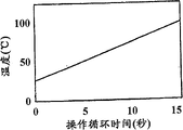
Figure 35 c is the curve map of temperature with respect to the operation cycle time; With
Figure 36 is the curve map of standardization pressure with respect to depth-width ratio.
The specific embodiment
As shown in figure 11, storage box 1 of the present invention roughly comprises exterior part 2, inner part 3 and laminate 5.Exterior part 2, inner part 3 and laminate 5 are assembled together to form storage box 1, it has the inside 120 that is used to hold one or more beverage ingredients, import 121, outlet 122, and with import 121 and outlet 122 links to each other and through the beverage flow paths of inside 120.Import 121 and outlet 122 are sealed by laminate 5 at first, and in use open by piercing through or cut laminate 5.Beverage flow paths limits by the space correlation between exterior part 2, inner part 3 and the laminate 5, and is as described below.Optionally include other parts in storage box 1, for example filter 4, as hereinafter further introducing.
The storage box 1 that has shown first pattern at Fig. 1 to 11.First pattern of storage box 1 is designed for distributing filter back product especially, for example bakes stir-fry and ground coffee or tealeaves.Yet the storage box 1 of this pattern and other pattern as described below can be used for other products, for example chocolate, coffee, tea, sweetener, sweet wine, spices, alcoholic beverage, flavouring milk, fruit juice, band pulp and juice, dip and sweets.
As can be seen from Fig. 5, the global shape of storage box 1 is circular or dish type, wherein stores up the diameter of box 1 or width much larger than its height.Main shaft X is through the center of exterior part, as shown in Figure 1.As a rule, the entire outer diameter of exterior part 2 is 74.5 millimeters ± 6 millimeters, and the integral outer height is 16 millimeters ± 3 millimeters.The volume of the storage box 1 that assembles is generally 30.2 milliliters ± 20%.According to the present invention, for the storage box of operating under the pressure up to 2.0 crust, the depth-width ratio of storage box is between 0.10 to 0.43, and for the storage box of operating under the pressure of 2.0 to 4.0 crust, the depth-width ratio of storage box is between 0.42 to 0.68.The depth-width ratio of the storage box of operating under the pressure less than 2.0 crust preferably is between 0.21 to 0.28.This depth-width ratio is defined as containing the ratio of maximum internal vertical height and inner 120 the inner width (being to be internal diameter under the situation of dish type at the storage box) of the inside 120 of one or more beverage ingredients.In described embodiment, maximum vertical height is 14.3 millimeters, and width (equaling diameter in this case) is 57.8 millimeters.As shown in figure 36, distributing the required pressure of beverage from storage box of the present invention changes according to the depth-width ratio of storing up box.Have been found that depth-width ratio between 0.10 to 0.43 is for being favourable making requirement that distributes the required pressure minimum of beverage and the extraction that during distribution makes beverage and bubbling between the maximum requirement for the realization balance.0.42 to 0.68 than large ratio of height to width applicable to the system of high pressure more, this is normally under the situation of the storage box that uses bigger volume.
The depth-width ratio of non-dish type storage box may be defined as the ratio of maximum height and ultimate range.
In closure tip 11 with main shaft X be the center be provided with inwardly towards hollow cylindrical extension 18.Clearly illustrate more that as Fig. 2 cylindrical extension 18 comprises step-like profile, it has first 19, second portion 20 and third part 21.First 19 is straight cylindrical.Second portion 20 is the shape of frustum, and inwardly diminishes.Third part 21 is that another is straight cylindrical, and is sealed by bottom surface 31.Diminish to the diameter incremental of first 19, second portion 20 and third part 21, make the diameter of cylindrical extension 18 in that the 11 sealing bottom surfaces 31 that extend to cylindrical extension 18 diminish from the top.Formed the shoulder 32 of approximate horizontal at the second portion 20 on the cylindrical extension 18 and the joint between the third part 21.
Formed towards the bottom 12 outward extending shoulder 33 outside in the parts 2.Outward extending shoulder 33 formed with coaxial second wall 15 of annular wall 13 so that limit circular orbit, it has formed header 16 between second wall 15 and annular wall 13.Header 16 extends round the periphery of exterior part 2.A series of notches 17 are located in the annular wall 13 and are concordant with header 16, so that provide gas and fluid connection between the inside 34 of header 16 and exterior part 2.As shown in Figure 3, notch 17 has constituted the vertical slits in the annular wall 13.Be provided with the notch between 20 to 40.In the embodiment shown, 37 notches 17 are roughly equally spacedly around the periphery setting of header 16.Notch 17 preferably has the length between 1.4 to 1.8 millimeters.The typical length of each notch is 1.6 millimeters, its be exterior part 2 whole height 10%.The width of each notch is between 0.25 to 0.35 millimeter.Usually, the width of each notch is 0.3 millimeter.The width of notch 17 should be enough narrow, with prevent between the storage life or in use beverage ingredient therefrom through and enter in the header 16.
Exterior part in the parts 22 periphery places have formed snout cavity 26 outside.Clearly illustrate that as Fig. 5 be provided with cylindrical wall 27, it defines snout cavity 26 therein, and the snout cavity 26 and the inside 34 of exterior part 2 are separated.Cylindrical wall 27 has the sealing end face 28 that is formed on perpendicular on the plane of main shaft X, and with the unlimited lower end 29 of bottom 12 coplanes of exterior part 2.Snout cavity 26 is connected with header 16 via two notches 30, as shown in Figure 1.Perhaps, can adopt one to four notch to come to form between header 16 and snout cavity 26 is communicated with.
The lower end of outward extending shoulder 33 is provided with outward extending flange 35, and it extends perpendicular to main shaft X.Typical flange 35 has the width between 2 to 4 millimeters.The part of flange 35 extends, to form the handle 24 that can hold exterior part 2 by it.Handle 24 is provided with the rim of upwards digging 25, so that promote grasping.
Illustrate best as Fig. 8, annular frame 41 comprises exterior rim 51 and the interior hub 52 that links to each other by ten equally spaced radial spokes 53.Interior hub 52 forms one with cylindrical funnel 40 and therefrom extends.Formed filtering holes 55 between the radial spoke 53 in annular frame 41.Filter 4 is located on the annular frame 41, so that cover filtering holes 55.Filter is preferably made by having than the material of high wet strength such as the nonwoven material of polyester.Spendable other material comprises fluid-tight cellulosic material, for example contains the cellulosic material of weaving the paper fiber.Weaving the paper fiber can be blended together with polypropylene, polyvinyl chloride and/or poly fiber.These plastic materials are combined in the cellulosic material, make cellulosic material to be heat-sealed.Filter 4 also can utilize and can be handled or apply by the material of heat and/or pressure activated, makes it to be sealed in like this on the annular frame 41.
Shown in the cross-sectional profiles of Fig. 7, interior hub 52 is located at the position lower than exterior rim 51, thereby makes annular frame 41 have the below profile of inclination.
The upper surface of each spoke 53 is provided with upright disc 54, and it is divided into a plurality of passages 57 with the void space of annular frame more than 41.Each passage 57 is limited by disc 54 on both sides, is limited by filter 4 on the bottom surface.Passage 57 extends downwards from exterior rim 51, and is passed in the cylindrical funnel 40 at the opening that the inner limited 56 places by disc 54.
Perhaps, inner part 3 and/or exterior part 2 can be made by Biodegradable polymeric.Degradable polyethylene (for example SPITEK that is provided by the Symphony Environmental company of Britain Borehamwood), biodegradable polyesteramide (for example BAK1095 that is provided by Symphony Environmental company), PLA (PLA that is provided by the Cargil company of Minn.), starch-based polymer, cellulose derivative and polypeptide are provided the example of suitable material.
The assembling of storage box 1 relates to following steps:
A) inner part 3 is inserted in the exterior part 2;
B) with filter 4 cutting formings and be placed on the inner part 3, so that be accommodated on the cylindrical funnel 40 and lean against on the annular frame 41;
C) by ultrasonic bonding inner part 3, exterior part 2 and filter 4 are combined;
D) fill storage box 1 with one or more beverage ingredients;
E) laminate 5 is fixed on the exterior part 2.
These steps will be described in further detail.
As being clearly shown that in Figure 11, exterior part 2 and inner part 3 are defining void space 130 under the annular lip 41 He outside the cylindrical funnel 40 in inner 120 when combining, and it has formed filter chamber.Filter chamber 130 and the annular frame passage 57 more than 41 is separated by filter paper 4.
Periphery formation weld seam 126 by surrounding layer pressing plate 5 is combined in laminate 5 on the bottom surface of the flange 35 that stretches out then, thereby laminate 5 is fixed on the exterior part 2.Weld seam 126 extends then, so that laminate 5 is sealed on the lower limb of cylindrical wall 27 of snout cavity 26.In addition, between the lower limb of the outer tube 42 of laminate 5 and cylindrical funnel 40, formed weld seam 125.Laminate 5 has formed the lower wall of filter chamber 130, and has sealed snout cavity 26 and cylindrical funnel 40.Yet, before distributing, between the lower limb of laminate 5 and spout 43, have little gap 123.Can adopt multiple welding method such as thermal weld and ultrasonic bonding, this depends on the material behavior of laminate 5.
Advantageously, inner part 3 is cross-placed between exterior part 2 and the laminate 5.Inner part 3 is by relatively the material such as the polypropylene of rigidity form.Like this, inner part 3 has formed bearing part, and it is used for making laminate 5 and exterior part 2 keep spaced apart when storage box 1 pressurized.Storage box 1 preferably in use affords the compressive load between 130 to 280N.This pressure is used to prevent to store up box and lost efficacy when inner pressurized, and can be used for inner part 3 and exterior part 2 are pressed together.This has guaranteed that the path in the storage box 1 and the inside dimension in hole fix, and can not change during the pressurized of storage box 1.
In order to use storage box 1, at first it is inserted in the beverage preparation machine, and opens import 121 and outlet 122 by the puncture component of beverage preparation machine, this puncture component is bored a hole laminate 5 and is folded up.The aqueous medium that is generally water enters storage box 1 by import 121 under pressure, enter snout cavity 26 under the pressure between the 0.1-2.0 crust.Flow through from being directed here notch 30 and flow of water around header 16, and enter the filter chamber 130 of storage box 1 through a plurality of notches 17.Water is forced to radially inwardly flow through filter chamber 130, and mixes with the beverage ingredient 200 that is wherein comprised.Water is forced upwardly through beverage ingredient simultaneously.Enter into the passage 57 of annular frame 41 tops via filter 4 and filtering holes 55 by the beverage that water is formed through beverage ingredient.Filter 4 on spoke 53 sealing and the welding of rim 51 and exterior part 2 guaranteed not exist shortcut, all beverages all must be through filter 4.
Beverage is flowed through opening 56 downwards and is entered in the cylindrical funnel 40 along being formed at radial passage 57 between the disc 54 then.Beverage arrives outlet 44 through spout 43 downwards along the passage 50 between the supporting disc 47, and here beverage is drained in reservoir vessel such as the cup.
Beverage preparation machine preferably includes the air cleaning means, wherein forces compressed air by storing up box 1, so that wash away the beverage that remains in the reservoir vessel when operation cycle finishes.
The storage box 1 that in Figure 12 to 18, has shown second pattern.The storage box 1 of second pattern is designed for distributing the product of espresso style to fry and ground coffee as roasting especially, wherein needs to produce the beverage of the band micro-bubble that is called crema.Therefore identical in many features of the storage box 1 of second pattern and first pattern adopt similar label to come feature like the representation class.To discuss the difference between first and second patterns in the following description.The common trait that works in the same manner will can not introduced in detail.
Identical in the annular frame 41 of inner part 3 and first pattern.Equally, filter 4 is located on the annular frame 41 so that cover filtering holes 55.The outer tube 42 of cylindrical funnel 40 is also with foregoing identical.Yet, to compare with first pattern, the structure of the inner part 2 of second pattern has many differences.As shown in figure 16, spout 43 is provided with separator 65, and it has extended a segment distance from exporting 44 towards the top of spout 43.Separator 65 helps to prevent that spraying and/or splash from appearring in beverage when leaving spout 43.The profile of spout 43 also is different, and comprises the step-like profile that has obvious bending section 66 near the upper end of pipe 43.
Air intlet 71 is located in the annular lip 47, and upwards aims in week with hole 70, shown in Figure 16 and 17.Air intlet 71 comprises the hole of passing flange 47, so as between outer tube 42 and the spout 43 flange more than 47 point and the void space of flange below 47 between connection is provided.Preferably as shown in the figure, air intlet 71 comprises cone frustum shaped portion 73 and following cylindrical part 72.Air intlet 71 forms by mould such as thimble usually.The tapered profiles of air intlet 71 allows that mould is easier to be taken out from moulding part.Near the walls air intlet 71 of being positioned at of outer tube 42 are configured as and can form skewed slot 75, import 45 that it leads to spout 43 from air intlet 71.As shown in figure 17, between air intlet 71 and skewed slot 75, formed corner cut shoulder 74, with can not make dirty immediately flange 47 upper surfaces of next-door neighbour's air intlet 71 of the beverage jet that guarantees to come from notch 70.
The linkage editor of the storage box 1 of second pattern is similar to the assembling of first pattern.Yet, have some differences.As shown in figure 18, the third part 21 of cylindrical extension 18 is placed in the supporting rim 67 but not is placed on the supporting disc.The shoulder 32 of the cylindrical extension 18 between second portion 20 and the third part 21 leans against on the top edge of supporting rim 67 of inner part 3.Therefore, formed boundary zone 124 between inner part 3 and exterior part 2, it comprises the face sealing between cylindrical extension 18 and supporting rim 67 of extending along the almost whole periphery of storage box 1.Although because the notch 70 of supporting in the rim 67 extends through supporting rim 67 and extend downward below the shoulder 68 any location point place, the sealing between cylindrical extension 18 and the supporting rim 67 is not that fluid seals.Therefore, cylindrical extension 18 and the interface fit of supporting between the rim 67 make notch 70 distortion pore-formings 128, clearly illustrate as Figure 18, thereby the connection of gas and liquid is provided between circular passage 69 and spout 43.The hole is generally 0.64 mm wide, 0.69 millimeters long.
The class of operation of the storage box 1 distribution beverage of second pattern is similar to the operation in first pattern, but has certain difference.Beverage in the radial passage 57 flows downward along the passage 57 that is formed between the disc 54, and enters into the circular passage 69 of cylindrical funnel 40 through opening 56.By being gathered in the back pressure of the beverage in filter chamber 130 and the passage 57, beverage is forced to from the circular passage 69 through via hole 128 under pressure.Therefore, beverage is forced through hole 128 as jet and enters by the formed expansion chamber in the upper end of spout 43.As shown in figure 18, beverage jet is directly crossed air intlet 71.When beverage entered spout 43, the pressure of beverage jet reduced.As a result, when air was upwards taken out through air intlet 71, air was entrained in the beverage flow with the form of a large amount of minute bubbles.The beverage jet that comes from hole 128 flows to outlet 44 downwards with the same form of funnel, and here beverage is discharged in reservoir vessel such as the cup, and wherein bubble has formed required crema.Therefore, hole 128 and air intlet 71 have formed the injection structure that is used for air is entrained in beverage together.Beverage enters the mobile held stationary as far as possible of injection structure to reduce the pressure loss.Advantageously, the wall of injection structure should be made into recessed, so that reduce the loss that causes because of " wall attachment effect " friction.The dimensional tolerance in hole 128 is less.Hole dimension is preferably 0.02 square millimeter of fixed value plus-minus.Can be in the outlet of injection structure or that hair, microfilament or other surface imperfection structure are set is long-pending to increase the effective cross section in the exit, have been found that this means can strengthen the degree that air is carried secretly.
The storage box 1 that in Figure 19 to 29, has shown the 3rd pattern.The storage box 1 of the 3rd pattern is designed for distributing soluble products especially, and it can be Powdered, liquid, pulpous state, gel or similar type.In use, soluble products is dissolved by aqueous medium during through storage box 1 or forms suspension at aqueous medium such as water.But the example of beverage comprises chocolate, coffee, milk, tea, soup or other rehydration or can water-soluble product.Therefore identical in many features of the storage box 1 of the 3rd pattern and the above-mentioned pattern adopt like numerals will to represent similar characteristics.To discuss the difference between the 3rd pattern and the above-mentioned pattern in the following description.The common trait that works in the same manner will can not introduced in detail.
Compare with the exterior part 2 of above-mentioned pattern, the exterior part 2 of the 3rd pattern inwardly towards hollow cylindrical extension 18 have bigger overall diameter, as shown in figure 20.Particularly, compare with 13.2 millimeters of the exterior part 2 that is used for above-mentioned pattern, the diameter of first 19 is usually between 16 to 18 millimeters.In addition, first 19 is provided with the outer surface 19a or the projection of protrusion, is clearly shown that as Figure 20, and its function is as described below.Yet the diameter of third part 21 of storage box 1 is identical, causes the area of the shoulder 32 in the storage box 1 of the 3rd pattern bigger.The typical volumes of having assembled storage box 1 is 32.5 milliliters ± 20%.
The quantity of the notch of annular wall 13 lower ends also is different with the location.Be provided with 3 to 5 notches.In the embodiment shown in Figure 23, four notches 36 are equally spacedly around the periphery setting of header 16.Notch 36 slightly wide than in the above-mentioned pattern storage box 1 is between 0.35 to 0.45 millimeter, is preferably 0.4 mm wide.
The exterior part 2 of storage box 1 is identical in others.
Identical in the structure of the cylindrical funnel 40 of inner part 3 and first pattern storage box 1 is provided with outer tube 42, spout 45, annular lip 47 and supporting disc 49.Unique difference is that spout 45 is configured as frustro-conical segment 92 and following cylindrical segment 93.
Compare with above-mentioned pattern, shown in Figure 24 to 28, annular frame 41 is replaced by sleeve part 80, sleeve part 80 round cylindrical funnel 40 and by 8 radially strut 87 connect thereon, strut 87 joins with cylindrical funnel 40 near annular lip 47 places or its.The cylindrical extension 81 of sleeve part 80 extends upward from strut 87, defines the chamber 90 that has open top face.The upper rim 91 of cylindrical extension 81 has the profile that turns over inwardly, as shown in figure 26.The annular wall 82 of sleeve part 80 is extended downwards from strut 87, defines circular passage 86 between sleeve part 80 and outer tube 42.
Annular wall 82 comprises outward flange 83 in the lower end, it is arranged perpendicular to main shaft X.Rim 84 dangles downwards from the bottom surface of flange 83, and comprises five holes 85 that circumferentially are provided with equally spacedly around rim 84.Therefore, rim 84 is provided with the bottom profiled of castellated.
Between strut 87, be provided with hole 89, thereby allow the connection between chamber 90 and the circular passage 86.
The linkage editor that is used for the 3rd pattern storage box 1 is similar to the assembling of first pattern, but has certain difference.Exterior part 2 and inner part 3 sucking fit as shown in figure 29 are in the same place, and fix by fastener matching structure but not weld together.In the process of these two parts combinations, inwardly towards cylindrical extension 18 is contained in the last cylindrical extension 81 of sleeve part 80.The friction-type that turns over rim 91 in the protrusion outer surface 19a of the first 19 by cylindrical extension 18 and the last cylindrical extension 81 is bonded with each other, and just inner part 3 can be fixed in the exterior part 2.By inner part 3 is located in the exterior part 2, just formed hybrid chamber 134 in the outside that is positioned at sleeve part 80.Hybrid chamber 134 included beverage ingredient 200 before distributing.It should be noted that upwards staggered each other in week in four imports 36 and five holes 85.The relative position of these two parts needn't be for that determine or fixing between erecting stage, this be because the use in four imports 36 and five holes 85 has guaranteed the relatively rotation place between these parts how, always out-of-alignment between import and hole.
One or more beverage ingredients are seated in the hybrid chamber 134 of storage box.The loading density of beverage ingredient in hybrid chamber 134 can change as required.
Then with laminate 5 with above pattern in above-mentioned same way as be fixed on exterior part 2 and the inner part 3.
In use, water with above pattern storage box in identical mode enter hybrid chamber 134 via four notches 36.Water is forced to radially inwardly pass through hybrid chamber, and mixes with the beverage ingredient that is included in wherein.Product is dissolved in the water or mixes with it, and has formed beverage in hybrid chamber 134, and the back pressure by beverage in the hybrid chamber 134 and water is driven through the hole 85 and enters into circular passage 86 then.Circumferentially staggering of four import notches 36 and five holes 85 guaranteed that water jet must at first circulate at hybrid chamber 134, could radially lead to hole 85 from import notch 36 then.The degree and the uniformity of the dissolving or the mixing of product have so just been improved significantly.Beverage is forced upwardly in circular passage 86 through the hole 89 between the strut 87 and enters into chamber 90.Beverage enters spout 43 through the import 45 between the supporting disc 49 from chamber 90, and flows to outlet 44, and here beverage is drained in reservoir vessel such as the cup.This storage box especially can be applicable to the beverage ingredient of viscous liquid or gel form.In one application, include the liquid chocolate composition in storage box 1, its viscosity at room temperature is between 1700 to 3900mPa, be between 5000 to 10000mPa under 0 ℃, and the solid refractive index is 67Brix ± 3.In another kind is used, in storage box 1, include liquid coffee, its viscosity at room temperature is between 70 to 2000mPa, is being between 80 to 5000mPa under 0 ℃, wherein coffee has the total solid level between 40 to 70%.The liquid coffee composition can contain the sodium bicarbonate between 0.1 to 2.0% weight, preferably between 0.5 to 1.0% weight.Sodium bicarbonate is used for the pH value level of coffee is maintained 4.8 or lower, thus make the storage box that is filled with coffee shelf-life reach 12 months.
The storage box 1 that in Figure 30 to 34, has shown the 4th pattern.The storage box 1 of the 4th pattern is designed to can be used for dispense liquid product such as condensed liquid milk especially.Therefore identical in many features of the storage box 1 of the 4th pattern and the above-mentioned pattern adopt like numerals will to come feature like the representation class.To discuss the difference between the 4th pattern and the above pattern in the following description.The common trait that works in the same manner will can not introduced in detail.
Identical in the storage box 1 of exterior part 2 and the 3rd pattern, and shown in Figure 19 to 23.
The cylindrical funnel 40 of inner part 3 be similar in second pattern storage box 1 shown in, but have certain difference.As shown in figure 30, spout 43 is configured as and has frustro-conical segment 106 and following cylindrical segment 107.On the inner surface of spout 43, be provided with three axial fins 105,, and prevent that the beverage of being discharged from circling round downwards in spout so that the beverage that is distributed is guided towards outlet 44.Therefore, fin 105 is as partition.Store up in the box 1 as second pattern, air intlet 71 is arranged to pass annular lip 47.Yet, longer in skewed slot 75 to the second patterns of air intlet 71 belows.
Sleeve part 80 be arranged to be similar in above-mentioned the 3rd pattern storage box 1 shown in.In rim 84, be provided with 5 to 12 holes 85.Be typically provided with 10 holes, but not as 5 holes in the storage box 1 of the 3rd pattern.
Identical in the linkage editor of the 4th pattern storage box 1 and the 3rd pattern.
The class of operation of the 4th pattern storage box is similar to the operation of the 3rd pattern.Water enters storage box 1 and hybrid chamber 134 with foregoing same way as.Water mixes with fluid product and with its dilution there, and it is forced in then under the bowl 100 and flows out, and flows to outlet 44 through via hole 85, as mentioned above.Being included in the water that part of fluid products in the annular bowl shown in Figure 34 100 are not entered hybrid chamber 134 at first dilutes immediately.On the contrary, the diluted fluid product in hybrid chamber 134 bottoms will tend to through the hole 85 and leave, and enter in the annular bowl 100 but not be forced upwardly via upper oral part 104.Therefore, compare with the product in hybrid chamber 134 bottoms, the fluid product in the annular bowl 100 remains more concentrated at the initial stage of operation cycle.Fluid product in the annular bowl 100 drops onto in the product stream that leaves hybrid chamber 134 via hole 85 below bowl 100 via feeding hole 103 under the gravity effect.Annular bowl 100 is used to make the concentration homogenising of the diluted fluid product that enters cylindrical funnel 40, this is by keeping a part of concentrated liquid product, and in whole operation circulation, it stably is discharged into to leave and realizes in the liquid stream flow path, shown in Figure 35 a, wherein shown the milk concentration of the existing total solid percentage of conduct measured during about 15 seconds operation cycle.Line a has shown the concentration curve that has bowl 100, and line b has shown the concentration curve that does not have the storage of bowl 100 box.Can see, the concentration curve that has cup 100 is more steady during operation cycle, does not have the initially bigger decline that resembles with not occurring concentration the bowl 100.As a rule, the initial concentration of milk is 30-35%SS, is 10%SS when circulation finishes.This has caused thinner ratio is about 3 to 1, yet the thinner ratio between 1 to 1 to 6 to 1 also can be used for the present invention.For other liquid beverage ingredients, this concentration can change.For example for liquid chocolate, initial concentration is about 67%SS, is 12-15%SS when circulation finishes.This causes the thinner ratio ratio of aqueous medium and beverage ingredient in the beverage (distribute) for about 5 to 1, yet the thinner ratio between 2 to 1 to 10 to 1 also can be used for the present invention.For liquid coffee, initial concentration is between 40-67%, and distributing the concentration when finishing is 1-2%SS, or the like.This causes thinner ratio between 20 to 1 to 70 to 1, yet the thinner ratio between 10 to 1 to 100 to 1 also can be used for the present invention.
By being gathered in the back pressure of the beverage in filter chamber 134 and the chamber 90, beverage is forced to the hole 128 of flowing through from circular passage 86 under pressure.Therefore, beverage is forced through hole 128 as jet, and enters in the expansion chamber that the upper end by spout 43 forms.As shown in figure 34, beverage jet is directly crossed air intlet 71.When beverage entered spout 43, the pressure of beverage jet descended.As a result, when air was upwards taken out through air intlet 71, air was entrained in the beverage flow with the form of a large amount of minute bubbles.The beverage jet that comes from the hole 128 flows to outlet 44 downwards with the form of funnel, and here beverage is discharged in reservoir vessel such as the cup, and wherein bubble has formed required foam-like outward appearance.
Advantageously, inner part 3, exterior part 2, laminate 5 and filter 4 all can easily carry out disinfection, and this is because these parts are discerptible, and does not all comprise zigzag channel or narrow gap individually.On the contrary, only the sterilization after after these parts combine together, just can form necessity path.This is even more important under the situation of beverage ingredient for milk base product such as liquid milk concentrate therein.
The 4th embodiment of beverage storage box can be particularly advantageous for distributing concentrated milk-based fluid product, for example liquid milk.Before, powdered dairy formula provides with the form that becomes bag, is used for adding to preprepared beverage.Yet, for the beverage of the neat promise style of Kapp, milk is bubbled.This realized through liquid milk product by making steam in the past.Yet this just must provide the steam supply source, thereby has increased the cost and the complexity of the machine that is used to distribute beverage.Use steam also to increase in the injured danger of operating period of storing up box.Therefore, the invention provides the beverage storage box that has concentrated milk-based fluid product therein.Have been found that for the milk of designated volume, concentrate, can produce the more foam of suckling than new fresh milk or UHT by making dairy produce.This has reduced the required size of milk storage box.Half fresh defatted milk contains have an appointment 1.6% fat and 10% total solid.Concentrated liquid dairy produce of the present invention contains fat between 0.1 and 12% and 25 to 40% total solid.In a typical case, goods contain 4% fat and 30% total solid.This enriched milk prods is suitable for adopting the low pressure draft machine as described below processing of bubbling.Particularly, the foaming of milk realizes under the pressure under 2 Palestine and Israels, is preferably about 1.5 crust when adopting the storage box of above-mentioned the 4th embodiment.
Concentrated milk's foaming is particularly advantageous for the beverage of neat promise of for example Kapp and milk shake.Milk is through via hole 128 and cross air intlet 71 and the best of bowl 100 uses the foaming level preferably can make milk greater than 40%, is preferably greater than 70%.For liquid chocolate, can realize foaming level greater than 70%.For liquid coffee, can realize foaming level greater than 70%.The foamability level is recently measured with foam volume that is produced and the liquid beverage ingredients volume that is distributed.For example, when the beverage that distributes 138.3 milliliters, if wherein 583 milliliters are foam, then foamability just is calculated as [58.3/ (138.3-58.3)] * 100=72.9%.The foamability of milk (with other liquid component) can be strengthened by bowl 100 is set, shown in Figure 35 b.(line is a) greater than the foamability (line b) of the milk that does not utilize bowl 100 to distribute to utilize the foamability of the milk that bowl 100 distributes.This is because of foamability of suckling and the positive correlation of milk concentration, and shown in Figure 35 a, bowl 100 makes milk keep higher concentration in a part of greatly operation cycle.Know that also the temperature positive correlation of the foamability of milk and aqueous medium is shown in Figure 35 c.Therefore, bowl 100 is favourable, because more milk remains in the storage box, up to finishing near operation cycle, this moment, aqueous medium was the warmmest.This has strengthened foamability again.
The storage box of the 4th embodiment also can be advantageously used in the dispense liquid coffee product.
Have been found that with the storage box of prior art and compare that the embodiment of beverage storage box of the present invention has advantageously provided the enhancing uniformity of institute's soaking beverage.See table 1, wherein shown contain that roasting is fried and 20 duplicate samples separately of the storage box A of ground coffee and B brew output capacity.Storage box A is the beverage storage box according to first embodiment of the invention.Storage box B is the beverage storage box of the prior art described in the applicant's document WO 01/58786.The refractive index of soaking beverage is that unit records with Brix, and adopts standard scale and formula to convert soluble solids percentage (%SS) to.In following example:
%SS=0.7774 * (Brix value)+0.0569
% output capacity=(%SS * brew volume (g))/(100 * coffee weight (g))
Table 1
Storage box A

Storage box B
Above data are carried out the analysis of t inspection statistics, draw following result:
Table 2
The t check: two samples, adopt mean square deviation

The analysis showed that the present invention stores up the storage box (under 95% confidence level) that uniformity that being converted into of box brew the % output capacity of concentration significantly is better than prior art, and compare that its standard deviation is 0.88% with 2.24% standard deviation of prior art storage box.This means that the beverage that utilizes storage box of the present invention to brew has more repeatability and has more uniform concentration.This is for liking its beverage to have equal flavour repeatedly and not wishing that brewing for the consumer who occurs random variation on the concentration be preferred.
The material of above-mentioned storage box can be provided with barrier coatings, to improve the repellence that it enters oxygen and/or moisture and/or other pollutant.Barrier coatings also can strengthen the repellence that prevents that beverage ingredient from spilling in the box from storage, but and/or the degree that leaches from storage box material of reduction meeting abstract that beverage ingredient is had a negative impact.The material of barrier coatings can be selected from PET, polyamide, EVOH, PVDC or metallization material.Barrier coatings can apply by many kinds of mechanism, includes but not limited to paste in the vapour deposition, vacuum moulding machine, plasma coating, co-extrusion, mould be coated with and two-stage/multistage molded.
Claims (11)
1. one kind is stored up box (1), and it contains one or more beverage ingredients (200) and is formed with material impervious to water by airtight basically, and described storage box comprises the storage chamber (130 that contains described one or more beverage ingredients; 134), described storage box also comprises and is located at described storage chamber (130; 134) and the filter (4) between at least a portion of the lower surface of the top of described storage box (11), between the top of described filter (4) and described storage box, formed one or more passage (57), described one or more passage (57) is communicated with the outlet (44) of described storage box, feasible one or more imports (17 with described storage chamber; 36) beverage flow paths that links up with described outlet (44) is upwards through described filter (4) and enter into described one or more passage (57), it is characterized in that, described storage box has the exterior part of dish type, described exterior part has central axis, and with described central axis be the center inwardly towards and the hollow cylindrical extension of sealing, described storage box is a dish type, and the depth-width ratio of the width of the vertical height of described storage chamber and described storage chamber is between 0.10 to 0.43.
2. storage box according to claim 1 (1) is characterized in that, the depth-width ratio of the vertical height of described storage chamber and the width of described storage chamber is 0.21 to 0.28.
3. storage box according to claim 2 is characterized in that, described depth-width ratio is about 0.25.
4. each described storage box (1) in requiring according to aforesaid right is characterized in that described one or more imports (17; 36) be oriented and radially enter in the described storage chamber.
5. storage box according to claim 4 is characterized in that, described one or more imports (17; 36) be located near the periphery place of described storage box (1) or its, so that flowing of aqueous medium radially upcountry is directed in the described storage chamber.
6. storage box according to claim 1 is characterized in that, described beverage ingredient (200) is fried and ground coffee for roasting.
7. storage box according to claim 1 is characterized in that, described passage (57) described filter with that opposite side of described storage box top, via the outlet pathway that separates with described storage chamber, and be communicated with the outlet (44) of described storage box.
8. one kind is used for from the method according to distribution beverage each described storage box (1) of aforesaid right requirement, it comprises step: make aqueous medium come from the beverage of described one or more beverage ingredients with formation by described storage box, and described beverage is assigned in the reservoir vessel, wherein, aqueous medium 0.1 to 2.0 the crust pressure under by described storage box.
9. the storage box (1) of a dish type, it uses the aqueous medium under 2.0 to 4.0 bar pressures, and comprise one or more beverage ingredients (200) and form by airtight and material impervious to water basically, described storage box comprises the storage chamber (130 that contains described one or more beverage ingredients; 134), it is characterized in that the depth-width ratio of the vertical height of described storage chamber and the width of described storage chamber is between 0.42 to 0.68, described storage box also comprises and is located at described storage chamber (130; 134) and the filter (4) between at least a portion of the lower surface of the top of described storage box (11), between the top of described filter (4) and described storage box, formed one or more passage (57), described one or more passage (57) is communicated with the outlet (44) of described storage box, feasible one or more imports (17 with described storage chamber; 36) beverage flow paths that links up with described outlet (44) is upwards through described filter (4) and enter into described one or more passage (57), and, described storage box has the exterior part of dish type, described exterior part has central axis, and with described central axis be the center inwardly towards and the hollow cylindrical extension of sealing.
10. storage box according to claim 9 is characterized in that, described passage (57) described filter with that opposite side of described storage box top, via the outlet pathway that separates with described storage chamber, and be communicated with the outlet (44) of described storage box.
11. method that is used for distributing beverage from storage box according to claim 9 (1), it comprises step: make aqueous medium come from the beverage of described one or more beverage ingredients by described storage box with formation, and described beverage is assigned in the reservoir vessel.
Applications Claiming Priority (2)
| Application Number | Priority Date | Filing Date | Title |
|---|---|---|---|
| GB0301708.4 | 2003-01-24 | ||
| GB0301708A GB2397498B (en) | 2003-01-24 | 2003-01-24 | Cartridge and method for the preparation of beverages |
Publications (2)
| Publication Number | Publication Date |
|---|---|
| CN1761424A CN1761424A (en) | 2006-04-19 |
| CN100548198C true CN100548198C (en) | 2009-10-14 |
Family
ID=9951777
Family Applications (1)
| Application Number | Title | Priority Date | Filing Date |
|---|---|---|---|
| CNB2004800074048A Expired - Lifetime CN100548198C (en) | 2003-01-24 | 2004-01-23 | Be used to prepare the storage box and the method for beverage |
Country Status (21)
| Country | Link |
|---|---|
| EP (1) | EP1440636B1 (en) |
| JP (3) | JP4624342B2 (en) |
| KR (1) | KR101073747B1 (en) |
| CN (1) | CN100548198C (en) |
| AR (1) | AR044748A1 (en) |
| AT (1) | ATE453350T1 (en) |
| AU (1) | AU2004206098A1 (en) |
| BR (1) | BRPI0406890A (en) |
| CA (1) | CA2513723C (en) |
| DE (1) | DE602004024837D1 (en) |
| ES (1) | ES2337138T3 (en) |
| GB (1) | GB2397498B (en) |
| HK (1) | HK1065691A1 (en) |
| LT (1) | LT2005073A (en) |
| MX (1) | MXPA05007868A (en) |
| NO (1) | NO20053938L (en) |
| PE (1) | PE20040887A1 (en) |
| PL (1) | PL206809B1 (en) |
| RU (1) | RU2337601C2 (en) |
| TW (1) | TWI324054B (en) |
| WO (1) | WO2004064584A1 (en) |
Families Citing this family (39)
| Publication number | Priority date | Publication date | Assignee | Title |
|---|---|---|---|---|
| GB2397498B (en) * | 2003-01-24 | 2006-01-04 | Kraft Foods R & D Inc | Cartridge and method for the preparation of beverages |
| GB2411106B (en) * | 2004-02-17 | 2006-11-22 | Kraft Foods R & D Inc | Cartridge for the preparation of beverages |
| US7926663B2 (en) * | 2005-05-06 | 2011-04-19 | Shin-Etsu Polymer Co., Ltd. | Substrate storage container and method of producing the same |
| NL1029312C2 (en) * | 2005-06-22 | 2006-12-27 | Friesland Brands Bv | Cup used to prepare beverage by means of hot water appliance has covering layer with liquid-permeable perforations and surface that serves as inlet aperture for receiving liquid suitable for preparation substance |
| WO2006137737A2 (en) * | 2005-06-22 | 2006-12-28 | Friesland Brands B.V. | Holder and cup with concentrate for preparation of hot beverages |
| ITGE20050010U1 (en) * | 2005-10-19 | 2007-04-20 | Ariete Spa | DISPOSABLE CARTRIDGE-FILTER FOR ESPRESSO COFFEE MACHINES. |
| AU2008231859B2 (en) * | 2007-03-23 | 2012-11-22 | Société des Produits Nestlé S.A. | Beverage ingredient capsule with opening plate having pressure-relief openings |
| DK2316310T3 (en) | 2007-06-05 | 2012-07-02 | Nestec Sa | System and method for preparing a food liquid from a food substance contained in a container by centrifugation |
| JP5400039B2 (en) | 2007-06-05 | 2014-01-29 | ネステク ソシエテ アノニム | Capsule and method for producing food liquid by centrifugation |
| US8431175B2 (en) | 2007-06-05 | 2013-04-30 | Nestec S.A. | Method for preparing a beverage or food liquid and system using brewing centrifugal force |
| US8409646B2 (en) * | 2007-06-05 | 2013-04-02 | Nestec S.A. | Single-use capsule for preparing a food liquid by centrifugation |
| CN101677706B (en) | 2007-06-05 | 2013-07-17 | 雀巢产品技术援助有限公司 | Method for preparing a beverage or liquid food and system using brewing centrifugal force |
| PT2330953E (en) | 2008-09-02 | 2015-09-09 | Nestec Sa | Method for preparing a food liquid contained in a capsule by centrifugation and system adapted for such method |
| EP2317897B1 (en) | 2008-09-02 | 2015-09-16 | Nestec S.A. | Controlled beverage production device using centrifugal forces |
| US9095236B2 (en) | 2008-12-09 | 2015-08-04 | Nestec S.A. | Liquid food preparation system for preparing a liquid food by centrifugation |
| WO2010137965A1 (en) * | 2009-06-17 | 2010-12-02 | Sara Lee/De N.V. | Capsule, system and method for the preparation of a beverage and a method for manufacturing such a capsule |
| CN102573582B (en) | 2009-06-17 | 2017-04-26 | 皇家戴维艾格伯茨有限公司 | System and method for preparing a quantity-on-schedule beverage suitable for consumption |
| EP2287090B1 (en) | 2009-08-19 | 2013-05-29 | Nestec S.A. | Capsule for the preparation of a coffee extract having a structure facilitating perforation for injection of water |
| US8658232B2 (en) | 2009-08-28 | 2014-02-25 | Nestec S.A. | Capsule system for the preparation of beverages by centrifugation |
| GB2475291B (en) * | 2009-11-12 | 2012-03-28 | Kraft Foods R & D Inc | Beverage preparation machines |
| MX2012006502A (en) * | 2009-12-08 | 2012-07-03 | Nestec Sa | Capsule system with flow adjustment means. |
| EP2510046A1 (en) | 2009-12-08 | 2012-10-17 | International Paper Company | Thermoformed articles made from reactive extrusion products of biobased materials |
| GB2481068B (en) | 2010-06-11 | 2012-06-20 | Kraft Foods R & D Inc | Cartridge for the preparation of beverages |
| EP2394932B1 (en) * | 2010-06-11 | 2013-06-05 | Alain Frydman | Capsule with weakened area |
| IT1401828B1 (en) * | 2010-09-28 | 2013-08-28 | Macchiavelli Srl | SYSTEM FOR THE PREPARATION OF A BEVERAGE FROM AN INFUSION PRODUCT CONTAINED IN AN INTERCHANGEABLE CAPSULE |
| GB2493211B (en) | 2011-07-29 | 2014-01-22 | Kraft Foods R & D Inc | A method and a system for making a beverage, and a beverage cartridge |
| WO2013076519A1 (en) * | 2011-11-22 | 2013-05-30 | Tuttoespresso S.R.L. | Capsule for beverage preparation |
| WO2013098681A1 (en) * | 2011-12-26 | 2013-07-04 | Koninklijke Philips Electronics N.V. | Apparatus for brewing ingredients in a solvent |
| CN104603027B (en) * | 2012-09-05 | 2017-08-11 | 雀巢产品技术援助有限公司 | Drink capsule with anti-drip film |
| US10450130B2 (en) * | 2012-09-12 | 2019-10-22 | Kraft Foods R & D, Inc. | Cartridges, systems and methods for preparation of beverages |
| US9783361B2 (en) | 2013-03-14 | 2017-10-10 | Starbucks Corporation | Stretchable beverage cartridges and methods |
| US10442610B2 (en) | 2014-03-11 | 2019-10-15 | Starbucks Corporation | Pod-based restrictors and methods |
| GB2527292A (en) * | 2014-06-13 | 2015-12-23 | Kraft Foods R&D Inc | Cartridge for the preparation of beverages |
| US9877495B2 (en) | 2015-01-09 | 2018-01-30 | Starbucks Corporation | Method of making a sweetened soluble beverage product |
| DE102015115250A1 (en) * | 2015-09-10 | 2017-03-16 | Pester Pac Automation Gmbh | Use of a packaging |
| EP3272672B2 (en) | 2016-07-19 | 2023-02-15 | Delica AG | Capsule |
| RU2754461C1 (en) | 2016-11-09 | 2021-09-02 | Пепсико, Инк. | Devices, methods and systems for preparation of carbonated beverages |
| WO2021177829A1 (en) | 2020-03-04 | 2021-09-10 | Liposoma Health B.V. | Cartridges containing lipid formulations for health ingredient-containing hot drinks |
| NL2029172B1 (en) | 2021-09-10 | 2023-03-21 | Liposoma Health B V | Lipid formulations for the preparation of health ingredient-containing hot drinks |
Citations (2)
| Publication number | Priority date | Publication date | Assignee | Title |
|---|---|---|---|---|
| US1576735A (en) * | 1921-10-08 | 1926-03-16 | Reginald A Fessenden | Infusor |
| US3083101A (en) * | 1959-04-06 | 1963-03-26 | Noury Jean | Refill for filtration coffee-pot |
Family Cites Families (8)
| Publication number | Priority date | Publication date | Assignee | Title |
|---|---|---|---|---|
| ATE93373T1 (en) * | 1990-07-27 | 1993-09-15 | Nestle Sa | METHOD FOR BREWING CLOSED PORTION PACKS AND APPARATUS FOR CARRYING OUT THESE METHOD. |
| DE69028628T2 (en) * | 1990-07-27 | 1997-01-30 | Nestle Sa | Closed cartridge for the preparation of a beverage and method and device for producing the same |
| CA2083324A1 (en) * | 1992-02-03 | 1993-08-04 | Shirdan J. Grykiewicz | Brew basket |
| GB9316717D0 (en) * | 1993-08-11 | 1993-09-29 | Gen Foods Ltd | Cartridge and method for the preparation fo whipped beverages |
| WO1995007648A1 (en) * | 1993-09-17 | 1995-03-23 | Mars G.B. Limited | Beverage brewing |
| WO1995016377A1 (en) * | 1993-12-13 | 1995-06-22 | Ferr-Max Kft. | Method of and apparatus for preparing a frothy coffee beverage, especially for household use |
| GB0003355D0 (en) | 2000-02-14 | 2000-04-05 | Kraft Jacobs Suchard Limited | Cartridge and method for the preparation of whipped beverages |
| GB2397498B (en) * | 2003-01-24 | 2006-01-04 | Kraft Foods R & D Inc | Cartridge and method for the preparation of beverages |
-
2003
- 2003-01-24 GB GB0301708A patent/GB2397498B/en not_active Expired - Lifetime
-
2004
- 2004-01-23 AT AT04250388T patent/ATE453350T1/en not_active IP Right Cessation
- 2004-01-23 JP JP2006500240A patent/JP4624342B2/en not_active Expired - Fee Related
- 2004-01-23 BR BR0406890-4A patent/BRPI0406890A/en not_active IP Right Cessation
- 2004-01-23 DE DE602004024837T patent/DE602004024837D1/en not_active Expired - Lifetime
- 2004-01-23 EP EP04250388A patent/EP1440636B1/en not_active Expired - Lifetime
- 2004-01-23 CA CA2513723A patent/CA2513723C/en not_active Expired - Lifetime
- 2004-01-23 CN CNB2004800074048A patent/CN100548198C/en not_active Expired - Lifetime
- 2004-01-23 MX MXPA05007868A patent/MXPA05007868A/en unknown
- 2004-01-23 ES ES04250388T patent/ES2337138T3/en not_active Expired - Lifetime
- 2004-01-23 WO PCT/GB2004/000282 patent/WO2004064584A1/en active Application Filing
- 2004-01-23 KR KR1020057013573A patent/KR101073747B1/en active IP Right Grant
- 2004-01-23 AR ARP040100195A patent/AR044748A1/en unknown
- 2004-01-23 PL PL377941A patent/PL206809B1/en unknown
- 2004-01-23 RU RU2005126733/12A patent/RU2337601C2/en active
- 2004-01-23 AU AU2004206098A patent/AU2004206098A1/en not_active Abandoned
- 2004-01-26 PE PE2004000099A patent/PE20040887A1/en not_active Application Discontinuation
- 2004-01-27 TW TW093101692A patent/TWI324054B/en not_active IP Right Cessation
- 2004-11-01 HK HK04108569.0A patent/HK1065691A1/en not_active IP Right Cessation
-
2005
- 2005-08-22 LT LT2005073A patent/LT2005073A/en not_active Application Discontinuation
- 2005-08-23 NO NO20053938A patent/NO20053938L/en not_active Application Discontinuation
-
2010
- 2010-09-27 JP JP2010215305A patent/JP5665457B2/en not_active Expired - Fee Related
-
2013
- 2013-12-04 JP JP2013251418A patent/JP5836353B2/en not_active Expired - Fee Related
Patent Citations (2)
| Publication number | Priority date | Publication date | Assignee | Title |
|---|---|---|---|---|
| US1576735A (en) * | 1921-10-08 | 1926-03-16 | Reginald A Fessenden | Infusor |
| US3083101A (en) * | 1959-04-06 | 1963-03-26 | Noury Jean | Refill for filtration coffee-pot |
Also Published As
Similar Documents
| Publication | Publication Date | Title |
|---|---|---|
| CN100548198C (en) | Be used to prepare the storage box and the method for beverage | |
| CN1802296B (en) | Cartridge and method for the preparation of beverages | |
| CN100564186C (en) | Be used to prepare the storage box of beverage | |
| CN101496696B (en) | Cartridge for the preparation of beverages and method of manufacturing the same | |
| US10676273B2 (en) | Cartridge and method for the preparation of beverages | |
| US7322277B2 (en) | Cartridge and method for the preparation of beverages | |
| US7533604B2 (en) | Cartridge system for the preparation of beverages and method of manufacturing said system | |
| EP1440907B2 (en) | Cartridge for the preparation of beverages | |
| CA3007411A1 (en) | Cartridge for the preparation of beverages and method of manufacturing a cartridge | |
| CA2513995C (en) | Cartridge for the preparation of beverages | |
| EP1440909B1 (en) | Cartridge system for the preparation of beverages and method of manufacturing said system | |
| MXPA06009388A (en) | Cartridge for the preparation of beverages |
Legal Events
| Date | Code | Title | Description |
|---|---|---|---|
| C06 | Publication | ||
| PB01 | Publication | ||
| C10 | Entry into substantive examination | ||
| SE01 | Entry into force of request for substantive examination | ||
| C14 | Grant of patent or utility model | ||
| GR01 | Patent grant | ||
| C41 | Transfer of patent application or patent right or utility model | ||
| TR01 | Transfer of patent right |
Effective date of registration: 20161229 Address after: Utrecht, Holland Province Patentee after: KONINKLIJKE DOUWE EGBERTS B.V. Address before: Munich, Germany Patentee before: KRAFT FOODS R & D, Inc. |
|
| CX01 | Expiry of patent term | ||
| CX01 | Expiry of patent term |
Granted publication date: 20091014 |