CN100557553C - Messaging device and control method thereof and image processing equipment - Google Patents
Messaging device and control method thereof and image processing equipment Download PDFInfo
- Publication number
- CN100557553C CN100557553C CNB2007101021965A CN200710102196A CN100557553C CN 100557553 C CN100557553 C CN 100557553C CN B2007101021965 A CNB2007101021965 A CN B2007101021965A CN 200710102196 A CN200710102196 A CN 200710102196A CN 100557553 C CN100557553 C CN 100557553C
- Authority
- CN
- China
- Prior art keywords
- image
- unit
- mixed reality
- fit
- virtual
- Prior art date
- Legal status (The legal status is an assumption and is not a legal conclusion. Google has not performed a legal analysis and makes no representation as to the accuracy of the status listed.)
- Expired - Fee Related
Links
Images


Classifications
-
- G—PHYSICS
- G06—COMPUTING; CALCULATING OR COUNTING
- G06T—IMAGE DATA PROCESSING OR GENERATION, IN GENERAL
- G06T15/00—3D [Three Dimensional] image rendering
- G06T15/10—Geometric effects
- G06T15/20—Perspective computation
Abstract
A kind of messaging device that is connected to display device comprises: acquiring unit is fit to obtain the real image of being caught by imaging device; Generation unit is fit to generate the virtual image based on the orientation of described imaging device; Detecting unit is fit to detect the inclination of real image; Correcting unit is fit to based on the described real image of described detected real image slant correction; Synthesis unit is fit to generate composograph based on the real image of proofreading and correct and the described virtual image; And output unit, be fit to composograph to described display device output calibration.
Description
Technical field
The present invention relates to messaging device and control method thereof and image processing equipment.More specifically, the present invention relates to the mixed reality technology.
Background technology
Many known systems based on the mixed reality technology (MR system or mixed reality system) are arranged, and this technology merges real world and virtual world and can not cause any discomfort with a kind of natural way.This MR system shows the mixed reality image on display device such as HMD, by merging the real image (actual sensed image) that is obtained by imaging device such as camera and using the virtual space image (virtual image) of CG (computer graphical) drafting to create this mixed reality image.By this process, the MR system provides mixed reality to its user.In the superincumbent description, CG represents computer graphical, and HMD represents head mounted display.
Because the virtual image of this MR system creation is to follow the tracks of the variation in the real image, so need catch the position and the orientation of user's observation point in real time.6-degree of freedom position and orientation sensors equipment are widely used in catch position and orientation.The MR system is with the position and the orientation of user's observation point, and is measured as 6-degree of freedom position and orientation sensors equipment, converts observation point position and orientation virtual in the Virtual Space to, uses CG to draw the virtual image, and merges the described virtual image and real image.Therefore, the user of MR system can observe the image of describing virtual objects thereon, just look like that they are present in the real space truly.
The user of MR system generally uses head fixed display device, as HMD.HMD is equipped with position and the approximate consistent video camera that disposes of optics of orientation with observer's observation point.The MR system that uses HMD obtains real image from the position and the orientation of the user's (observer) that wears HMD observation point, and creates from identical position and the observed virtual space image of orientation.As a result, this MR image can strengthen the observer and immerses wherein sensation.
On the other hand, the MR system that uses HMD has been arranged, only had the observer who wears HMD to observe the mixed reality image, and the 3rd people who does not wear HMD can not observe the mixed reality image.Reason for this reason, the same mixture real world images that is presented to described observer is displayed on fixed display devices such as CRT, projector or the big display, to present to unspecific the 3rd people.Therefore, the 3rd people who does not even wear HMD can experience the same mixture reality that the observer experienced of wearing HMD.
In the case, the 3rd people will observe the mixed reality image of creating from described observer's observation point.If the observer move or tilt his/her head, even the 3rd people is maintained fixed, will be presented to the 3rd people corresponding to described observer's the position and the mixed reality image of the variation in the orientation.Therefore, for example, when the observer tilt for downward fixation object his/she the time, the mixed reality image of inclination will be presented on observer's the HMD, and simultaneously, the mixed reality image of inclination will be presented on the fixed display devices that the 3rd people sees.Because the mixed reality image is created with on the HMD that is presented at the observer, therefore, significantly, this mixed reality image is suitable for the observer.But, because the 3rd people can not tilt in the mode identical with the observer when watching described fixing display, so the 3rd people will feel inevitably that the mixed reality image that presents is to tilt artificially with the inconsistent angle of his head tilt.In addition, constantly change owing to wear the observer's of HMD the position and the orientation of head, the nature of the 3rd people sensation of above mentioned observation fixed display devices will increase.Therefore, when mixed reality image that observation post presents, it is uncomfortable that the 3rd people may finally feel.
In other words, use MR system as mentioned above, have such situation: the mixed reality image that is suitable for the observer of his/her head may be unsuitable for the 3rd people, and the position of the observation point that the 3rd people has and orientation are different from this observer's observation point position and orientation.Therefore, require to be presented to the observer corresponding to the mixed reality image that changes in observer's position and the orientation, the mixed reality image that does not have the inclination that position and the variation in the orientation by described observer cause simultaneously is presented to the 3rd people.
Publication number be in the Jap.P. of 10-164426 disclosed Electrofax control with the image that is recorded, constant vertical orientated to keep by the orientation that detects imaging plane.
But publication number is that disclosed Electrofax is carried out in the Jap.P. of 10-164426 processing is limited in the sense of rotation that detects image-generating unit and angle and based on the image rotation of described testing result.Therefore, foregoing invention can not can not present suitable mixed reality image to the 3rd people who does not wear HMD to the observer who wears HMD.
Summary of the invention
Consider that the problems referred to above make the present invention, and its target provides the technology that can present suitable mixed reality image to the observer who wears HMD and the 3rd people who does not wear HMD.
In order to realize above target, messaging device is connected to display device, and messaging device comprises:
Acquiring unit is fit to obtain the real image of being caught by imaging device;
Generation unit is fit to generate the virtual image based on the orientation of imaging device;
Detecting unit is fit to detect the inclination of real image;
Correcting unit is fit to the slant correction real image based on detected real image;
Synthesis unit is fit to generate composograph based on the real image of proofreading and correct and the virtual image;
Output unit is fit to the composograph to the display device output calibration.
In addition, another messaging device is configured as follows according to the present invention.That is,
Messaging device is connected to display device, and messaging device comprises:
Acquiring unit is fit to obtain the real image of being caught by imaging device;
Generation unit is fit to generate the virtual image based on the orientation of imaging device;
Synthesis unit is fit to generate composograph based on the real image and the virtual image;
Detecting unit is fit to detect the inclination of real image;
Correcting unit is fit to based on detected real image slant correction composograph; With
Output unit is fit to the composograph to the display device output calibration.
In addition, a kind of image processing equipment comprises:
Image acquisition unit is fit to obtain image;
Detecting unit is fit to the inclination of detected image;
Image generation unit is fit to generate image, to generate composograph with this image;
Correcting unit, the suitable image that obtains based on the testing result correcting image acquiring unit of detecting unit;
First synthesis unit is fit to generate composograph based on the image of image that is generated by image generation unit and correcting unit correction;
First output unit is fit to the composograph that output first synthesis unit generates.
In addition, another image processing equipment is configured as follows according to the present invention.That is,
A kind of image processing equipment comprises:
Image acquisition unit is fit to obtain image;
Detecting unit is fit to detect the inclination of described image;
Image generation unit is fit to generate image, to generate composograph with this image;
Synthesis unit is fit to generate composograph based on the image of image that is obtained by image acquisition unit and image generation unit generation;
Correcting unit is fit to proofread and correct the composograph that is generated by the image synthesis unit based on the testing result of detecting unit; With
First output unit is fit to the image that the output calibration unit is proofreaied and correct.
In addition, being used for the messaging device control method according to the present invention disposes as follows.That is,
A kind of control method that is used for messaging device, this control method comprises:
Obtain the image acquisition step of image;
The detection step that detected image tilts;
The image that generates image generates step, generates composograph with this image;
Proofread and correct the aligning step of the image that obtains in image acquisition step based on the testing result that detects step;
Based on generating image that generates in the step and the image of in aligning step, proofreading and correct, generate first synthesis step of composograph at image; With
The first output step of the composograph that output generates in first synthesis step.
In addition, another control method that is used for messaging device according to the present invention disposes as follows.That is,
A kind of control method that is used for messaging device, control method comprises:
Obtain the image acquisition step of image;
Detect the detection step of described image inclination;
The image that generates image generates step, uses this image to generate composograph;
Generate the image that generates in the step based on the image of in image capture step, catching with at image, generate first synthesis step of composograph;
Proofread and correct the aligning step of the composograph that in the image synthesis step, generates based on the testing result that detects step; With
The first output step of the image that output is proofreaied and correct in aligning step.
In addition, another messaging device configuration according to the present invention is as follows.That is,
A kind of image processing equipment has display device, second display device and is connected to display device and the messaging device of second display device, and this image processing equipment comprises:
Acquiring unit is fit to obtain the real image of being caught by imaging device;
Detecting unit is fit to detect the inclination of real image;
Correcting unit is fit to based on the described real image of detected real image slant correction; With
Output unit is fit to the real image to the display device output calibration, and exports the described real image that acquiring unit obtains to second display device.
According to the description below with reference to the example embodiment of accompanying drawing, more features of the present invention will become obvious.
Description of drawings
Fig. 1 is a block diagram, and the summary according to the functional configuration of the image processing equipment of first embodiment is shown;
Fig. 2 is the explanation synoptic diagram of the processing of image rotary unit execution;
Fig. 3 is a process flow diagram, shows the treatment scheme of being carried out by image processing equipment;
Fig. 4 is a block scheme, shows the summary according to the functional configuration of the image processing equipment of second embodiment;
Fig. 5 shows the block diagram according to the functional configuration summary of the image processing equipment of the 3rd embodiment;
Fig. 6 shows the block diagram according to the functional configuration summary of the image processing equipment of the 4th embodiment;
Fig. 7 is the process flow diagram that the treatment scheme of being carried out by image processing equipment is shown;
Fig. 8 shows the block diagram according to the functional configuration summary of the image processing equipment of the 5th embodiment;
Fig. 9 shows the block diagram according to the functional configuration summary of the image processing equipment of the 6th embodiment;
Figure 10 shows the block diagram of the hardware configuration summary of image processing equipment;
Figure 11 shows the block diagram according to the functional configuration summary of the image processing equipment of the 7th embodiment;
Figure 12 shows the block diagram according to the functional configuration summary of the image processing equipment of the 8th embodiment;
Figure 13 shows the block diagram according to the functional configuration summary of the image processing equipment of the 9th embodiment;
Figure 14 is the synoptic diagram that occurs defective after describing to rotate in the image; With
Figure 15 is the explanation synoptic diagram that finishing is handled.
Embodiment
Describe the preferred embodiments of the present invention in detail referring now to accompanying drawing.But, it should be noted that the parts of Miao Shuing only are indicative in conjunction with the embodiments, and do not limit the scope of the invention.
[first embodiment]
(the summary configuration of image processing equipment)
In first embodiment, will provide the description of following configuration, the image of being observed by the observer who wears HMD and experience mixed reality in this configuration is output to HMD and fixing display.In this case, common mixed reality image is displayed on the HMD, and the mixed reality image of correct tilt is displayed on the fixing display simultaneously.
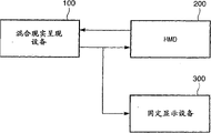
Figure 10 shows the block diagram of the hardware configuration summary of the image processing equipment according to the present invention.Rectangle shown in Figure 10 represents to realize the module of the configuration according to the present invention.Image or signal flows between the arrow representation module.
Mixed reality display device (messaging device) the 100th is carried out the module according to image processing equipment major function of the present invention.Based on the output of the image-generating unit 101 that provides from HMD 200 and position and orientation measuring unit 102, mixed reality display device 100 is created the mixed reality image, and shows the image of being created on HMD 200 and fixed display devices 300.Image-generating unit 101 and position and the orientation measuring unit 102 of HMD 200 will be described after a while.
In fact, can realize mixed reality display device 100 by messaging device (as personal computer or workstation).In this case, mixed reality display device 100 comprises CPU, CPU control entire equipment and memory storage (as RAM, ROM or (firmly) dish), and by executive routine code control and treatment.But, realize that the method for described mixed reality display device 100 is not limited to this layout, and described mixed reality display device 100 can be configured to the SIC (semiconductor integrated circuit) of carrying out same treatment.
As the following detailed description, mixed reality display device 100 obtains captive real image from image-generating unit 101, creates the virtual image based on the orientation of HMD 200 (image-generating unit 101), and detects the inclination of real image.In addition, mixed reality display device 100 is created composograph based on the real image of being proofreaied and correct respectively and the virtual image, and export described composograph on fixed display devices 300 based on the described real image of real image slant correction and the virtual image that detect.
HMD 200 (according to second display device of the present invention) is a display device, installs or be fixed on HMD on his/her head such as the observer.HMD 200 shows the image that is input to HMD 200 at observer's optics at the moment.In the present embodiment, HMD 200 is equipped with built-in video camera, and this camera is installed to be consistent with the position and the approximate optics of orientation of observer's observation point.The video camera that is built in HMD200 obtains the observed real image in observation point position from the observer, and to the described image of mixed reality display device 100 outputs.In addition, HMD 200 has the position of the observation point of measuring the observer and the function of orientation, and to measured position and the orientation information of mixed reality display device 100 outputs.Notice that HMD200 need not be restricted to the display device on the head that is configured to be installed in the observer.For example, be configured to be held in the display device that waits in observer's the hand and can carry out 200 identical functions with HMD.
Fixed display devices (display device) 300 is large-screen display equipments, as plasma display, and shows from the image of mixed reality display device 100 outputs on screen.Fixed display devices 300 allows the 3rd people who is different from the observer who uses HMD 200 can watch the mixed reality image.
The software that realization is equivalent to those functions of above-mentioned each equipment can be configured to replace described hardware device.
In addition, though explain that in order to be easy to the image processing equipment of present embodiment is described to be characterised in that top three modules configured, the configuration of image processing equipment is not limited to this example.For example, configurable top three modules are so that realize by individual equipment.For example, replacedly, present embodiment can be configured to by the mixed reality display device 100 that is built in HMD 200 or fixed display devices 300 and realizes.For example, replaceable choosing ground is distributed to the parts of Virtual Realization on a plurality of messaging devices and uses described messaging device to carry out parallel processing by the function with described mixed reality display device 100, disposes and realize present embodiment.
(functional configuration of image processing equipment)
Referring now to the functional configuration of Fig. 1 description according to the image processing equipment of present embodiment.Fig. 1 is the block diagram that illustrates according to the functional configuration summary of the image processing equipment of present embodiment.
In Fig. 1, image-generating unit 101 obtains the actual sensed image of observing from observer's observation point (real image).In the present embodiment, be built in the function of the video camera realization image-generating unit 101 among the HMD 200.The real image that is obtained by image-generating unit 101 is output to the image rotary unit 106a and the first image synthesis unit 107.
Position that provides on the HMD 200 and orientation measuring unit 102 are measured the position and the orientation of observer's observation point in three dimensions, and to tilt detection unit 104 and virtual image generation unit 105 described position of output and orientations.Described position and orientation measuring unit 102 are by for example 6-degree of freedom sensor (but being not limited to it) realization of measurement mechanism.For example, replacedly, image-generating unit 101 is caught the designator (mark) that is disposed in the space and the coordinate that detects described designator from the image of catching come estimated position and orientation by being provided with, and described space has known three-dimensional position.Position of Ji Suaning and orientation can be output to tilt detection unit 104 and virtual image generation unit 105 in this way.Like this, will be imported into position and orientation measuring unit 102 from the real image of image-generating unit 101 outputs.
103 storages of virtual information storage unit are used to generate the virtual image generation unit 105 employed virtual image spatial informations of the virtual image.When generating the virtual image, virtual information storage unit 103 provides Virtual Space information to virtual image generation unit 105.In the present embodiment, the Virtual Space is rendered as the necessary information of three-dimensional CG image, for example the synthetic and texture image of CG Three-dimension Target shape information, placement information, light source information, object about placing in virtual world is saved as Virtual Space information.About the information of 3D shape comprise apex coordinate, about the information of surface configuration, normal vector or the like.
Tilt detection unit 104 receives information about the observer's that wears HMD 200 observation point orientation as input from position and orientation measuring unit 102, and detect the inclination of real image, and the inclination that detects to image rotary unit 106a and 106b output based on orientation information.In the present embodiment, extract the inclination that a roll angle (roll angle) detects real image in the orientation information by position from be installed in HMD 200 and 102 outputs of orientation measuring unit, when observation point was given as described turning axle, roll angle was a rotation angle.By calculate the rotation matrix three dimensions from the orientation information of position and 102 outputs of orientation measuring unit, and with matrix decomposition is each component of roll angle (roll angle), the angle of pitch (pitch angle) and deflection angle (yaw angle), carries out the extraction of roll angle.Tilt detection unit 104 is to the roll angle of image rotary unit 106a and 106b output extraction.When roll angle is included in the orientation of being measured by position and orientation measuring unit 102, and when position and orientation measuring unit 102 can directly be exported roll angle, tilt detection unit 104 was exported the roll angle of being imported and need not be revised image rotary unit 106a and 106b.Present embodiment provides two image rotary units, and tilt detection unit 104 is to two image rotary unit 106a and 106b output roll angle.
Based on the information from position and orientation measuring unit 102 and virtual information storage unit 103, virtual image generation unit 105 is carried out CG and is drawn to generate the virtual image.Virtual image generation unit 105 is to the virtual image of image rotary unit 106b and the 107 output generations of image synthesis unit.More specifically, virtual image generation unit 105 is set to an observation point from the position and the orientation of position and 102 outputs of orientation measuring unit, observes the Virtual Space from this observation point.Based on this observation point will be kept at CG object placement in the virtual information storage unit 103 in the Virtual Space after, virtual image generation unit 105 is drawn and is generated the virtual image by carrying out CG.
Based on the image inclination from tilt detection unit 104 outputs, each image rotary unit 106a and 106b apply rotational transform at the image from image-generating unit 101 or 105 outputs of virtual image generation unit, to offset described image inclination.In the present embodiment, owing to, will rotate described input picture with the reverse direction of described roll angle from the roll angle (being rotation angle when observation point is given as turning axle) of tilt detection unit 104 outputs from observer's observation point.
Fig. 2 is the explanation block diagram by the processing of image rotary unit 106 execution.For example, suppose that image 10 and-45 roll angles of spending before the rotation have been input to image rotary unit 106.Image 10 before 106 pairs of rotations shown in Figure 2 of image rotary unit is carried out rotational transform, to offset the roll angle of-45 degree.In other words, image 10 rotations+45 degree before image rotary unit 10 will rotate, and the image 20 after the output rotation.
When with (u, v)
TThe coordinate of each pixel in the image 10 before the expression rotation is when with (u ', v ')
TThe coordinate of each pixel in the image 20 after the expression rotation, and the roll angle of input is when representing with θ, each pixel in the image 20 after the formulate rotation below available, here rotation center be given as (u, v)
T=(0,0)
T
[formula 1]
For example, can use in picture centre or the image point coordinate corresponding to the optical centre of image-generating unit 101 etc. as rotation center.Can calculate the optical centre of image-generating unit 101 by the calibration of image-generating unit 101 grades.Because the concrete grammar at calculating optical center has been a common practise, its description will be omitted.
Image processing equipment according to the present invention comprises two image rotary unit 106a and 106b (they will be labeled as 106 jointly).The first image rotary unit (according to the first image rotary unit of the present invention) 106a receive from the real image of image-generating unit 101 outputs and from the roll angle of tilt detection unit 104 outputs as input, and the image after the 108 output rotations 20 of the second image synthesis unit.The second image rotary unit (according to the second image rotary unit of the present invention) 106b receive from the virtual image of virtual image generation unit 105 outputs and from the roll angle of tilt detection unit 104 outputs as input, and the image after the 108 output rotations 20 of the second image synthesis unit.
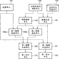
The virtual image that the first image synthesis unit (according to second synthesis unit of the present invention) 107 generates virtual image generation unit 105 is added on the real image that image-generating unit 101 catches, to generate the mixed reality image.The second image synthesis unit 108 is added to the postrotational virtual image of second image rotary unit 106b output on the postrotational real image of first image rotary unit 106a output, to generate the mixed reality image.The mixed reality image that is generated by the first image synthesis unit 107 outputs on first display unit 109, and the mixed reality image that is generated by the second image synthesis unit 108 outputs on second display unit 110.
As mentioned above, image processing equipment according to the present invention comprises two image synthesis units 107 and 108.The first image synthesis unit 107 receive from the real image of image-generating unit 101 outputs and from the virtual image of virtual image generation unit 105 outputs as input, and the mixed reality image that generates to 109 outputs of first display unit.The second image synthesis unit 108 (according to first synthesis unit of the present invention) receives image after the rotation 20 of two image rotary unit 106a and 106b output respectively as input, and the mixed reality image that is generated to 110 outputs of second display unit.In the present embodiment, the first image synthesis unit 107 and the second image synthesis unit 108 at first are added to the virtual image on the real image.Background parts to the virtual image is not carried out overlap-add procedure.Real image is added to the part except described background of the virtual image.The result of overlap-add procedure is that in the mixed reality image of the first image synthesis unit 107 and 108 generations of the second image synthesis unit, the virtual image will be only by the part that has Virtual Space CG in the described real image that partly is added to.
Also the part that has the virtual image of Virtual Space CG at random can be set to not carry out the part of stack, so that create special-effect.For example, make the virtual image not be added to the part of the real image that comprises particular color, can avoid always observing the phenomenon of Virtual Space CG in the real object front by carrying out to handle.For example use publication number can carry out this processing as disclosed method in the Jap.P. of 2003-296759.In the present embodiment, only having any different between the first image synthesis unit 107 and the second image synthesis unit 108 be, to the source module of image synthesis unit input picture with from the purpose module of image synthesis unit output image.In addition, the first image synthesis unit 107 is identical with the contents processing of the second image synthesis unit, 108 execution.
First display unit (according to second output unit of the present invention) 109 receives mixed reality image from 107 outputs of the first image synthesis unit as input, and shows the mixed reality image of being imported.Second display unit (according to first output unit of the present invention) 110 receives mixed reality image from 108 outputs of the second image synthesis unit as input, and shows the mixed reality image of being imported.Provide first display unit 109 at HMD 200, and this display unit shows the mixed reality image of observing from the observer's that uses HMD 200 observation point.In other words, first display unit, 109 display image rotary units 106 are not applied to rotational transform the mixed reality image on it as yet.Provide second display unit 110 on fixed display devices 300, and this display unit shows the mixed reality image of observing from the observer's that uses HMD 200 observation point, wherein image inclination is removed from the mixed reality image.In other words, second display unit, 110 display image rotary units 106 have been applied to rotational transform the mixed reality image on it.In the present embodiment, the display device with screen is as second display unit 110, and this screen is bigger than the screen of first display unit 109.This permission will be worn the observed mixed reality image of observer of HMD200 and be presented to the 3rd people who does not wear HMD 200.
(base conditioning)
Provide the description of the control of carrying out according to the image processing equipment of present embodiment referring now to Fig. 3, dispose this equipment as mentioned above.Fig. 3 shows the process flow diagram of the treatment scheme of carrying out according to the image processing equipment of present embodiment.Be stored in unshowned memory storage according to the program code shown in the process flow diagram,, and read and carry out by CPU such as the dish device or the RAM that in image processing equipment, provide.
At first, in step S1010, activate image processing equipment, and carry out necessary initialization according to present embodiment.Necessary initialization comprise that CPU carries out from dish device program code read or Virtual Space information processing, and it is stored among the RAM.
In step S1020, image-generating unit 101 obtains real image from the observer's that wears HMD 200 observation point.
In step S1030, position and orientation measuring unit 102 are measured the position and the orientation of the observer's who wears HMD 200 observation point.
In step S1040, tilt detection unit 104 detects the real image that obtains and tilts in step S1020.
In step S1050, virtual image generation unit 105 uses position and the orientation measured in step S1030 to carry out the CG drafting of Virtual Space as observation point, and generates the virtual image.
In step S1060, image rotary unit 106 is applied to rotational transform the virtual image that generates among the real image that obtains among the step S1020 and the step S1050.
In step S1070, the first image synthesis unit 107 and the second image synthesis unit, 108 reception real images and the virtual image are as input, and generation mixed reality image, and wherein the virtual image is added on the real image.As mentioned above, present embodiment comprises two image synthesis units 107 and 108.The composograph of the virtual image that generates among real image that obtains among the first image synthesis unit, the 107 formation step S1020 and the step S1050, and to first display unit, 109 output composographs.The second image synthesis unit 108 forms real image that obtains among the step S1020 and the composograph that rotational transform is applied to the virtual image on it in step S1060, and to second display unit, 110 output composographs.
In step S1080, determine about whether stopping this processing.If finish processing according to embodiment.On the contrary, if not, handle and return step S1020, continue therefrom.
It should be noted that in the present embodiment, in a series of processing of short time cycle execution in step S1020 to S1080.This series of processes of finishing one way needs the time usually within several milliseconds to hundreds of milliseconds.Therefore, by the processing of repeated execution of steps S1020, be presented at the mixed reality image that changes in the short cycle continuously according to the image processing equipment of present embodiment to S1080.Therefore, observer and the 3rd people are a series of mobile images with described mixed reality image recognition.
Though the description according to control flow of the present invention is provided above, the order of describing only is exemplary, and can revise the order of section processes.For example, can at random revise the order of processing, as long as the processing of execution in step S1020 before the processing of step S1060, the processing of execution in step S1030 before the processing of step S1040, and the processing of execution in step S1040 before the processing of step S1060.But, the order of immutable step S1010, S1070 and S1080.
As mentioned above, mixed reality display device 100 obtains the real image of having caught from image-generating unit 101, creates the virtual image based on the orientation of HMD 200 (image-generating unit 101), and detects the inclination of real image.In addition, mixed reality display device 100 tilts to proofread and correct the real image and the virtual image based on the real image that detects, and creates composograph based on each the self-tuning real image and the virtual image, and composograph is outputed on the fixed display devices 300.Therefore, tilt based on the real image that detects, to the image of fixed display devices 300 output calibrations.Therefore, can be respectively present suitable mixed reality image according to the configuration of first embodiment to observer who wears head fixed display device (HMD) and the 3rd people that do not wear head fixed display device.
[second embodiment]
According to the image processing equipment of second embodiment to HMD 200 and fixing display 300 outputs by wearing HMD and experiencing the image that the observer saw of mixed reality.In this case, common mixed reality image is displayed on the HMD, and the mixed reality image of slant correction is displayed on the fixing display 300.Though in the configuration of the configuration of second embodiment and control and first embodiment with exist many similarly between controlling, in the method that is used to detect the real image medium dip, second embodiment is different from first embodiment.In configuration, the position that obtains by position that provides in HMD 200 and orientation measuring unit 102 is provided and is orientated the inclination that detects real image according to first embodiment.But, in configuration, use the real image that obtains by image-generating unit 101 to detect inclination according to second embodiment.
Fig. 4 is a block scheme, shows the summary according to the graphics processing unit functional configuration of present embodiment.Compare with the functional configuration (Fig. 1) according to first embodiment, tilt detection unit 104 is with its difference, has replaced the orientation that input is exported from position and orientation measuring unit 102, and its input is from the real image of image-generating unit 101 outputs.About the configuration of present embodiment, its part that is different from first embodiment only will be described now.
In the present embodiment, image-generating unit 101 is exported the real image that is obtained to image rotary unit 106a, image synthesis unit 107 and tilt detection unit 104.In addition, in the present embodiment, position and orientation information that position and orientation measuring unit 102 are measured to 105 outputs of virtual image generation unit.
In the present embodiment, tilt detection unit 104 receives real image from image-generating unit 101 as input, and detects the inclination of this image.The inclination that tilt detection unit 104 detects to 106 outputs of image rotary unit.Tilt detection unit 104 is roll angle of image calculation of image-generating unit 101 outputs, and when observation point was given as turning axle, described roll angle was a rotation angle.The roll angle that tilt detection unit 104 is extracted to 106 outputs of image rotary unit.
Processing according to the performed calculating roll angle of the tilt detection unit 104 of present embodiment will be described below.Tilt detection unit 104 calculates the light stream since the real image of image-generating unit 101 outputs.The translational speed of each point on the light stream indicating image.A plurality of methods are to calculate the known method of light stream, such as method or the block matching method based on gradient.In the present embodiment, when the initial point of the displacement vector of light stream is represented by A, its terminal point represented by B, and the center of image is when being represented by O, for each displacement vector reckoner is shown the angle of ∠ AOB, and to image rotary unit 106 its mean values of output as a roll angle.
In the superincumbent description, though calculate roll angle based on the light stream in the image by tilt detection unit 104, present embodiment is not limited to this setting.As long as can obtain observer's sight line rotation angle on every side from the image that image-generating unit 101 obtains, any method all can be used for realizing the function of tilt detection unit 104.
As mentioned above, the real image that obtains according to the Allocation Analysis of present embodiment tilts with detection.Therefore,, still can detect the inclination of real image, so that with appropriate mode correcting image even HMD 200 can not detect orientation.Therefore, dispose the 3rd people that appropriate mixed reality image can be presented to the observer who wears head fixed display device (HMD) and do not worn head fixed display device according to second embodiment.Obviously, the method that the detection real image of describing in conjunction with present embodiment tilts can not only be applied to the configuration according to first embodiment, and is applied to the configuration according to the 3rd embodiment that below will describe.
[the 3rd embodiment]
According to the image processing equipment of the 3rd embodiment to HMD 200 and fixing display 300 outputs by wearing HMD and experiencing the image that the observer saw of mixed reality.In this case, common mixed reality image is displayed on the HMD 200, and the mixed reality image of correct tilt is displayed on the fixing display 300.Though in the configuration of the configuration of the 3rd embodiment and control and first embodiment with exist many similarly between controlling, the 3rd embodiment is different from first embodiment on the method for virtual image medium dip being used to detect.Configuration according to first embodiment is carried out correction by the virtual image that rotation is generated.On the contrary, present the orientation of Virtual Space, and generate the virtual image in view of the above according to the arrangement corrects of the 3rd embodiment.In other words, generate the virtual image under the correct tilt state according to being configured in of the 3rd embodiment.
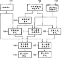
Fig. 5 shows the block diagram according to the functional configuration summary of the image processing equipment of present embodiment.Compare with functional configuration (Fig. 1), an image rotary unit 106 is only arranged now, and increase second virtual image generation unit 111 newly according to first embodiment.
In the present embodiment, mixed reality display device 100 obtains the real image of being caught by image-generating unit 101, detects the inclination of real image, and based on the real image slant correction real image that detects.In addition, mixed reality display device 100 tilts to generate the virtual image based on the orientation of image-generating unit 101 (HMD 200) and the real image of detection, generates composograph based on the real image of proofreading and correct and the virtual image, and to fixed display devices 300 output composographs.
About the configuration and the control of present embodiment, now only the part that it is different from first embodiment will be described.In the present embodiment, position and orientation measuring unit 102 are to the position and the orientation information of tilt detection unit 104, virtual image generation unit 105 and the 111 output measurements of second virtual image generation unit.In addition, in the present embodiment, tilt detection unit 104 is exported the inclination that is detected to the image rotary unit 106 and second virtual image generation unit 111.
Based on the information from position and orientation measuring unit 102, virtual information storage unit 103 and tilt detection unit 104, second virtual image generation unit 111 is carried out CG and is drawn to generate the virtual image.The virtual image that generates is sent to the second image synthesis unit 108.In the mode identical with virtual image generation unit 105, based on observer's observation point being kept at after the CG object is placed in the Virtual Space in the virtual information storage unit 103, second virtual image generation unit 111 is carried out CG and is drawn to generate the virtual image.At this moment, based on roll angle, from the orientation of position and 102 outputs of orientation measuring unit, remove the roll angle component from tilt detection unit 104.More specifically, calculate roll angle, the angle of pitch and deflection angle from the three-dimensional rotation matrix R that represents described orientation.Subsequently, use the angle of pitch and deflection angle to carry out another calculating, to obtain three-dimensional rotation matrix R '.In other words, the angle that obtains from R, only abandon roll angle (the roll angle component is set to 0) and make up R '.As a result, second virtual image generation unit 111 generates the virtual image, removes observer's sight line (on the picture plane of the virtual image) rotation on every side from this virtual image.
When roll angle is included in the orientation that position and orientation measuring unit 102 measure, and position and orientation measuring unit 102 be can directly export described roll angle the time, and second virtual image generation unit 111 only needs the roll angle of input to be set to 0 degree and carries out CG and draw.In the case, will not need from tilt detection unit 104 outputs.
In the present embodiment, the second image synthesis unit 108 receive by the real image of image-generating unit 106 outputs and by the image after the rotation 20 of the virtual image of second virtual image generation unit, 111 outputs as input, and the mixed reality image that generates to 110 outputs of second display unit.
In step S1050 shown in Figure 3, use image processing equipment according to present embodiment, the virtual image generation unit 105 and second virtual image generation unit 111 generate the virtual image.
As mentioned above, in the present embodiment, mixed reality display device 100 obtains the real image of being caught by image-generating unit 101, detects the inclination of real image, and tilts to proofread and correct real image based on the real image that detects.In addition, mixed reality display device 100 tilts to generate the virtual image based on the orientation of image-generating unit 101 (HMD 200) and the real image of detection, generates composograph based on the real image of proofreading and correct and the virtual image, and to fixed display devices 300 output composographs.
Therefore, be different from first embodiment,, and do not rotate the virtual image itself according to the configuration rotation observation point (carrying out CG from this observation point draws) of present embodiment.Therefore, the defective that causes owing to rotation is not appearing in the virtual image.Therefore, dispose and to present suitable mixed reality image to observer who wears head fixed display device (HMD) and the 3rd people who does not wear head fixed display device according to the 3rd embodiment.
[the 4th embodiment]
According to the image processing equipment of the 4th embodiment to HMD 200 and fixing display 300 outputs by wearing HMD and experiencing the image that the observer saw of mixed reality.In this case, common mixed reality image is displayed on the HMD 200, and the mixed reality image of correct tilt is displayed on the fixing display 300.Though the configuration of the 4th embodiment and control are with the configuration of first embodiment and exist many similar between controlling, in first embodiment, all proofread and correct the described real image and the virtual image but replaced, according to being configured in of the 4th embodiment with the be added to inclination of correcting image after the real image of the virtual image.
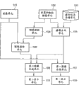
Fig. 6 shows the block diagram according to the functional configuration summary of the image processing equipment of present embodiment.Compare with first embodiment, an image rotary unit 106 is only arranged now, and omitted the second image synthesis unit 108.
In the present embodiment, mixed reality display device 100 obtains the real image of catching from image-generating unit 101, creates the virtual image based on the orientation of image-generating unit 101 (HMD 200), generates composograph based on the real image and the virtual image, and detects the inclination of real image.In addition, mixed reality display device 100 is based on the real image slant correction composograph that detects, and to fixed display devices 300 output composographs.
About the configuration and the control of present embodiment, its part that is different from first embodiment only will be described now.In the present embodiment, virtual image generation unit 105 is to the virtual image of first image synthesis unit 107a output generation.In addition, in the present embodiment, the first image synthesis unit 107a receive from the real image of image-generating unit 101 outputs and from the virtual image of virtual image generation unit 105 outputs as input, and the mixed reality image that generates to first display unit 109 and 106 outputs of image rotary unit.In addition, in the present embodiment, image rotary unit 106 receive from the mixed reality image of first image synthesis unit 107a output and from the roll angle of image rotary unit 104 outputs as input, and the image after the 110 output rotations 20 of second display unit.
The control of the present embodiment of configuration as mentioned above will be described now.Fig. 7 is the process flow diagram that the treatment scheme of carrying out according to the image processing equipment of present embodiment is shown.Compare with the control (Fig. 3) of first embodiment, deleted the processing of step S1060 and the processing of increase step S1075.
In step S1070, the first image synthesis unit 107 receives real images and the virtual image as input, and generate the wherein virtual image and be added to mixed reality image on the real image, and the mixed reality image that generates to image rotary unit 106 and 109 outputs of first display unit.
In step S1075, image rotary unit 106 is applied to the mixed reality image that generates among the step S1070 with rotational transform, and to second display unit, 110 output images.Next handle and proceed to step S1080.
As mentioned above, in the present embodiment, mixed reality display device 100 obtains the real image of catching from image-generating unit 101, creates the virtual image based on the orientation of image-generating unit 101 (HMD 200), and generates composograph based on the real image and the virtual image.In addition, mixed reality display device 100 detects the inclination of real image, tilts to proofread and correct composograph based on the real image that detects, and to fixed display devices 300 output composographs.
Seen in according to the configuration of present embodiment, owing to, can use the configuration of realization according to present embodiment relatively simply is set only to virtual image carries out image treatment for correcting from 107 outputs of the first image synthesis unit.Therefore, as mentioned above, can present suitable mixed reality image to observer who wears head fixed display device (HMD) and the 3rd people who does not wear head fixed display device according to the 4th embodiment configuration.
[the 5th embodiment]
According to the image processing equipment of the 5th embodiment to HMD 200 and fixing display 300 outputs by wearing HMD and experiencing the image that the observer saw of mixed reality.In this case, common mixed reality image is displayed on the HMD 200, and the mixed reality image of common mixed reality image or correct tilt is displayed on the fixing display 300.Though the configuration of the 5th embodiment and control are with the configuration of first embodiment and exist many similar between controlling, but the 5th embodiment is different from first embodiment is to be added to functional configuration on it, and it allows the user to choose whether the mixed reality image that second display unit 110 shows is carried out slant correction.
Fig. 8 shows the block diagram according to the functional configuration summary of the image processing equipment of present embodiment.Compare with first embodiment, the 5th embodiment increased selected cell 112.About the configuration and the control of present embodiment, its part that is different from first embodiment only will be described now.
In the present embodiment, tilt detection unit 104 receives control signal from selected cell 112 as input, and the image inclination that detects to image rotary unit 106 and 111 outputs of second virtual image generation unit.When the control signal from selected cell 112 outputs was set to forbid the processing of tilt detection unit 104, tilt detection unit 104 was to the roll angle of image rotary unit 106 outputs 0 degree.Otherwise tilt detection unit 104 is carried out and identical in other embodiments processing.
As mentioned above, the configuration according to the 5th embodiment allows the user at random to select whether the mixed reality image that shows on second display unit 110 to be carried out slant correction.Though having provided the example of present embodiment describes, wherein selected cell 112 is increased to configuration according to first embodiment, but alternatively selected cell 112 is added to the configuration of other embodiment, and carry out above-mentioned treatment for correcting and if only if the user just is provided with when selecting to carry out this treatment for correcting.
[the 6th embodiment]
According to the image processing equipment of the 6th embodiment to HMD 200 and fixing display 300 outputs by wearing HMD and experiencing the image that the observer saw of mixed reality.In this case, common mixed reality image is presented on the HMD 200, and the mixed reality image of common mixed reality image or correct tilt is presented on the fixing display 300.In the configuration of the configuration of the 6th embodiment and control and first and the 5th embodiment with exist many similar between controlling.But, being different from first embodiment, a functional configuration has been added on the 6th embodiment, and it allows the user to choose whether the mixed reality image that second display unit 110 shows is carried out slant correction.In addition, though the 5th embodiment is set to switch whether carry out slant correction by the 104 pairs of images in control slant correction unit, the 6th embodiment is set in the image output of correct tilt and do not have between the image output of correct tilt switch, and selects thus whether image to be carried out slant correction.
Fig. 9 shows the block diagram according to the functional configuration summary of the image processing equipment of present embodiment.Compare with first embodiment, the 6th embodiment increased selected cell 112.About the configuration and the control of present embodiment, its part that is different from first embodiment only will be described now.
In the present embodiment, selected cell 112 receives mixed reality image from two image synthesis units 107 and 108 as input, and selects the one of any of mixed reality image, and the image of selecting to 110 outputs of second display unit.In this case, carry out the selection of mixed reality image based on the instruction of user's input.
In other words, selected cell 112 also is the user interface that uses as by the user, to select whether image is carried out correction.
In the present embodiment, the input media (as switch, keyboard or mouse) of user's operation is connected to image processing equipment.Offer two selections of user, i.e. " correcting image inclination " and " not correcting image inclination ".Based on the input of user to input media, selected cell 112 is selected any one of mixed reality image.Selected cell 112 shows these selections on display, and accepts user's selection.When the user selected " correcting image inclination ", selected cell 112 outputs were from the mixed reality image of the second image synthesis unit, 108 outputs.When user's input " not correcting image inclination ", selected cell 112 outputs are from the mixed reality image of the first image synthesis unit, 107 outputs.
As mentioned above, the configuration according to the 6th embodiment allows the user at random to select whether the mixed reality image that shows on second display unit 110 to be carried out slant correction.Though having provided the example of present embodiment describes, wherein selected cell 112 is increased to configuration according to first embodiment, but replacedly can be increased to selected cell 112 configuration of other embodiment, and carry out above-described treatment for correcting and if only if the user just is provided with when selecting to carry out this treatment for correcting.
[the 7th embodiment]
According to the equipment of the 7th embodiment to HMD 200 and fixing display 300 outputs by wearing HMD and experiencing the image that the observer saw of mixed reality.In this case, common mixed reality image is displayed on the HMD 200, and the mixed reality image of common mixed reality image or correct tilt is displayed on the fixing display 300.In the configuration of the configuration of the 7th embodiment and control and the 5th embodiment with exist many similar between controlling.But, be different from the 5th embodiment, a functional configuration is added on the 7th embodiment, and it controls whether the mixed reality image of second display unit, 110 demonstrations is carried out slant correction automatically according to the attribute that is kept at CG in the virtual information storage unit 103.
Figure 11 shows the block diagram according to the functional configuration summary of the image processing equipment of present embodiment.Compare with the 5th embodiment, selected cell 112 and its difference are to accept the output from virtual information storage unit 103.About the configuration and the control of present embodiment, its part that is different from the 5th embodiment only will be described now.
In the present embodiment,,, make that character information can be along with the observer who wears HMD 200 moves always virtual image generation unit 105 is to use direction in the image that shows on first display unit 109 to generate the virtual image of character information even when relating to observation point and move.Therefore, in the present embodiment, when virtual information storage unit 103 when virtual image generation unit 105 output comprises the CG object of character information, be controlled at suitably by the inclination of correcting image not and show the mixed reality image that comprises character information on second display unit 110.Proofread and correct the inclination of the mixed reality image that does not comprise character information in the mode identical with first embodiment.
In the present embodiment, if virtual information storage unit 103 is exported the CG object that comprises character information to virtual image generation unit 105, selected cell 112 is selected, and the processing of tilt detection unit 104 is forbidden in this selection.But present embodiment is not limited to this setting.For example, can start or forbid the selection of slant correction according to the attribute beyond the character.
In addition, the output of selected cell 112 acceptance of the 6th embodiment from virtual information storage unit 103 can be set, make selected cell 112 receive mixed reality image from two image synthesis units 107 respectively as input, select the mixed reality image, and export the image of selecting to second display unit 110.In this case, will carry out about starting and forbid the control of correcting image inclination processing as described in conjunction with present embodiment.Obviously, can realize similar advantage in this case.
As mentioned above, according to the 7th embodiment, can control to switch whether image is carried out slant correction automatically according to the attribute that is kept at the CG in the virtual information storage unit 103 now.Though what provided that the example of present embodiment describes is increased to selected cell 112 configuration according to first embodiment, but replacedly selected cell 112 can be increased to the configuration of other embodiment, and carry out above-mentioned treatment for correcting and if only if the user just is provided with when selecting to carry out this treatment for correcting.
[the 8th embodiment]
According to the image processing equipment of the 8th embodiment to HMD 200 and fixing display 300 outputs by wearing HMD and experiencing the image that the observer saw of mixed reality.In this case, common mixed reality image is displayed on the HMD 200, and the mixed reality image of common mixed reality image or correct tilt is displayed on the fixing display 300.Though the configuration of the 8th embodiment and control are with the configuration of the 3rd embodiment and exist many similar between controlling, but be different from the 3rd embodiment, the 8th embodiment do not carry out slant correction according to the attribute that is kept at the CG in the virtual information storage unit 103 to the part of CG with particular community.
Figure 12 shows the block diagram according to the functional configuration summary of the image processing equipment of present embodiment.Compare with the 3rd embodiment, the 3rd virtual image generation unit 113 is further joined the 8th embodiment.About the configuration and the control of present embodiment, its part that is different from the 3rd embodiment only will be described now.
Based on the information from position and orientation measuring unit 102 and virtual information storage unit 103, the 3rd virtual image generation unit 113 is carried out CG and is drawn to generate the virtual image.The virtual image that the 3rd virtual image generation unit 113 generates to 108 outputs of the second image synthesis unit.Although the detail of the processing of the 3rd virtual image generation unit 113 is identical with virtual image generation unit 105, but in the present embodiment, the 3rd virtual image generation unit 113 is only carried out the CG object that comprises character information in the CG object that is stored in virtual information storage unit 103 and is presented.
In the present embodiment, second virtual image generation unit 111 is only carried out the CG object that does not comprise character information in the CG object that is stored in virtual information storage unit 103 and is presented.The details of other processing is identical with the 3rd embodiment.Can use determining that whether the method execution character information described in conjunction with the 7th embodiment exist.
The second image synthesis unit 108 receive respectively real image rotation 20 images that obtain from image-generating unit 106 output, from the virtual image of the correct tilt of second virtual image generation unit, 111 outputs, and from the virtual image of the not correct tilt of the 3rd virtual image generation unit 113 outputs as input.The mixed reality image that the second image synthesis unit 108 generates to 110 outputs of second display unit.
The configuration present embodiment makes carries out slant correction to the CG object that does not comprise character information in the CG object that is saved, and the CG object that comprises character information is not carried out slant correction.But present embodiment is not limited to this setting.For example, can use character information attribute in addition that the CG object class is become carries out those objects of slant correction and it is not carried out those objects of slant correction it.
As mentioned above, according to the 8th embodiment, automatically perform according to the attribute that is kept at the CG object in the virtual information storage unit 103 and to determine whether image is carried out slant correction, and control treatment for correcting according to this definite result.In other words, the CG expecting image is not carried out slant correction will not carry out slant correction to image, and the mixed reality image of correct tilt will be presented to other CG.Therefore, according to the attribute of CG, suitable image can be offered fixed display devices 300.Selected cell 112 is increased to configuration according to first embodiment though provided the example of present embodiment in describing, but replacedly selected cell 112 is increased to the configuration of other embodiment, and carries out above-mentioned treatment for correcting and if only if the user just is provided with when selecting to carry out this treatment for correcting.
[the 9th embodiment]
According to the image processing equipment of the 9th embodiment to HMD 200 and fixing display 300 outputs by wearing HMD and experiencing the image that the observer saw of mixed reality.In this case, common mixed reality image is displayed on the HMD 200, and the mixed reality image of correct tilt is displayed on the fixing display 300.Though in the configuration of the configuration of the 9th embodiment and control and first embodiment with exist many similar between controlling, but be different from first embodiment, it is feasible only to real image execution slant correction that the 9th embodiment is set, and slant correction is not carried out in the virtual image.For example, when determining to be kept at CG object in the virtual information storage unit 103 and all form, only real image is carried out slant correction by character information.
Figure 13 shows the block diagram according to the functional configuration summary of the image processing equipment of present embodiment.Compare with first embodiment, the 9th embodiment difference is that an image rotary unit 106 is only arranged now.About the configuration of present embodiment, its part that is different from first embodiment only will be described now.
In the present embodiment, mixed reality display device 100 obtains the real image of catching from image-generating unit 101, creates the virtual image based on the orientation (image-generating unit 101) of HMD 200, detects the inclination of real image, and based on the real image slant correction real image that detects.In addition, mixed reality display device 100 generates composograph based on the real image of slant correction and the described virtual image, and to the composograph of fixed display devices 300 output calibrations.
In the present embodiment, based on the information from position and orientation measuring unit 102 and virtual information storage unit 103, virtual image generation unit 105 is carried out CG and is drawn to generate the virtual image.The virtual image that virtual image generation unit 105 generates to 107 outputs of the first image synthesis unit.
In the present embodiment, the second image synthesis unit 108 is added to the uncorrected virtual image of virtual image generation unit 105 outputs from the postrotational real image of image rotary unit 106 outputs.The mixed reality image that the second image synthesis unit 108 generates is output to second display unit 110.
As mentioned above, be restricted under the situation about all constituting, only real image carried out slant correction according to the configuration of the 9th embodiment is feasible by character information at the CG object.
[the tenth embodiment]
According to the image processing equipment of the tenth embodiment to HMD 200 and fixing display 300 outputs by wearing HMD and experiencing the image that the observer saw of mixed reality.In this case, common mixed reality image is displayed on the HMD 200, and the mixed reality image of correct tilt is displayed on the fixing display 300.Though the configuration of the tenth embodiment and control are with the configuration of first embodiment and exist many similar between controlling, but be different from first embodiment, the mixed reality image that the tenth embodiment is set to slant correction has been applied thereon is carried out the finishing of effective coverage.By this execution, the configuration of present embodiment can stop in the mixed reality image and defective occur.
Has the identical summary of functional configuration (Fig. 1) with first embodiment according to the functional configuration of the image processing equipment of present embodiment.About the configuration of present embodiment, its part that is different from first embodiment only will be described now.
In the present embodiment, the second image synthesis unit 108 is carried out finishing in addition, and is generated the mixed reality image in the postrotational virtual image of exporting from other image rotary unit 106 from the postrotational real image stack of two image rotary units, 106 outputs.The mixed reality image that the second image synthesis unit 108 generates to 110 outputs of second display unit.The finishing of carrying out according to the second image synthesis unit 108 of present embodiment will be described now.
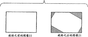
In the present embodiment, from the postrotational mixed reality image of image rotary unit 106 outputs defective is appearring.Figure 14 describes the synoptic diagram that occurs defective in the postrotational image 21, and it is by being rotated in the image that rotation image 11 is before created.Because the zone that the shadow region is represented in the image 21 after the rotation is not present in the rotation image 11 before, can not represent this zone in the image 21 after the rotation.Therefore, in the image 21 after rotation defective has appearred.
In the present embodiment, as shown in figure 15, finishing is carried out in the effective coverage of the image 20 after the rotation, to obtain finishing image 30.Figure 15 is the explanation synoptic diagram figure by the finishing of the second image synthesis unit, 108 execution.In this case, finishing is meant the processing in image that outputs to fixing display unit 300 and the rectangular image that fixedly comprises in the lap of the viewing area of display unit 300.What note is, the limit of rectangular image is parallel to any one of each limit of viewing area.
Usually, according to the angle (roll angle) of image with its rotation, the effective coverage difference of the image 20 after the rotation.In the present embodiment, for the image 20 after the rotation, always carry out the finishing of effective coverage with the roll angle of 90 degree no matter how many rotation angle is.As a result, to the arbitrarily angled finishing image 30 that all can obtain not have defective.
In addition, in the present embodiment, though also carry out the finishing of mixed reality image except the configuration according to the image processing equipment of first embodiment, finishing also can be applicable to the configuration according to the second and the 4th to the 9th embodiment.But, when with above-mentioned finish applications to according to the configuration of the 4th embodiment the time, will carry out finishing by image rotary unit 106.
As mentioned above, in configuration according to present embodiment, extract and output at output image and the rectangular image that fixedly comprises in the overlapping portion of the viewing area of display unit 300, make one of each limit of rectangular image be parallel to any one side of viewing area.Therefore, the configuration according to present embodiment allows to present the mixed reality image that does not have owing to rotating the defective that is caused.
[the 11 embodiment]
According to the image processing equipment of the 11 embodiment to HMD 200 and fixing display 300 outputs by wearing HMD and experiencing the image that the observer saw of mixed reality.In this case, common mixed reality image is presented on the HMD 200, and the mixed reality image of correct tilt is presented on the fixing display 300.Though the configuration of the 11 embodiment and control are with the configuration of first embodiment and exist many similar between controlling, but be different from first embodiment, the 11 embodiment is set to detect relative tilt with respect to the image of certain reference value to proofread and correct.The state (for example, when watching an object attentively downwards) of wearing HMD 200 observers' head tilt can be used as a reference now, proofread and correct the inclination of the mixed reality image that on fixed equipment 300, shows.In other words, keep the mixed reality image that shows on the fixed display devices 300 wherein constant by described reference value this state that tilts.
Summary according to the functional configuration of present embodiment is identical with first embodiment (Fig. 1).About the configuration of present embodiment, its part that is different from first embodiment only will be described now.
In the present embodiment, tilt detection unit 104 receive from position and orientation measuring unit 102 about the information of the observer's that wears HMD 200 observation point orientation as input, detect the inclination of real image, and export the inclination that detects to image rotary unit 106.In the present embodiment, extract the inclination that a roll angle detects described real image by the orientation of position from be installed in HMD 200 and 102 outputs of orientation measuring unit, wherein described roll angle is a rotation angle when described observation point is turning axle.At this moment, from the roll angle that extracts, deduct a rotary reference value, and the value after subtracting is transmitted to image rotary unit 106.Described rotary reference value is kept among the disc apparatus that does not show that provides in the mixed reality display device 100 or the RAM etc., and is set up in the initialization procedure of image processing equipment according to present embodiment.In replacement is provided with, can operates by the user of the input block that provides separately in the image processing equipment and revise described rotary reference value.
As mentioned above, use the configuration according to the 11 embodiment, it is constant by reference value this state that tilts to be maintained fixed the mixed reality image that shows on the display device 300 now.
[other embodiment]
Though described example of the present invention embodiment exemplary above in detail, the present invention can take form to be for example system, equipment, method, program or storage medium.More specifically, the present invention can be applicable to system that is made of multiple arrangement or the equipment that is made of single assembly.
The present invention also comprises such certain situation, realize that here the software program of the foregoing description function is offered system or equipment by direct or long-range, and described function is by the computer realization that reads and carry out the system or equipment program code that provides.
Therefore, program code itself (it will be installed to computing machine so that the calculating function realizes function of the present invention and processing) also is included in technical scope of the present invention.In other words, the present invention also comprises the computer program itself of realizing function of the present invention and processing.
In this case, as long as the prewired program function, the form that program can be taked for example for object code, compiler executable program or supply with OS be used for the execution script data.
For example, provide the recording medium of program to comprise soft (registered trademark) dish, hard disk, CD, magneto-optic disk, MO, CD-ROM, CD-R, CD-RW, tape, Nonvolatile memory card, ROM, DVD (DVD-ROM, DVD-R) etc.
Provide other method of program can comprise these situations, wherein the browser of client computer is used to connect the Internet home page, downloading into recording medium such as hard disk according to computer program of the present invention or the compressed file with automatic installation function.In addition, also can be divided into by the program code that will comprise program of the present invention a plurality of files with and download each file from different homepages and realize the present invention.In other words, www server also is included in the present invention, and www server allows to download the program code of realizing function of the present invention and processing on computers by a plurality of users.
In addition, also can provide program by at first encoding according to program of the present invention and coded program being stored in storage medium such as the CD-ROM that will distribute to the user.Subsequently, will allow the user who satisfies certain condition to download the key message of decoding from homepage by the Internet.Described key message can be used for carrying out described coded program so that it to be installed on computers, to realize the present invention.
By also can realize the function of the foregoing description by the computing machine execution fetch program.In other words, by the processing that the OS etc. by operation on computers carries out, can realize the function of the foregoing description, wherein OS etc. is based on the actual treatment instruction operating part or all from program.
In addition, expand the storer that mainboard provides, also can realize the function of the foregoing description by the function that makes described program read, be written to the functional expansion unit that is inserted into computing machine or is connected to computing machine from storage medium.In other words, come operating part or all actual treatment based on programmed instruction, also can finish the function of the foregoing description by CPU of providing on expansion board or the functional expansion unit etc.
According to the present invention, a kind of technology can be provided, can present suitable mixed reality image respectively to observer who wears HMD and the 3rd people who does not wear HMD.
Though reference example embodiment describes the present invention, will be appreciated that to the invention is not restricted to disclosed example embodiment.The broadest explanation of scope of following claim will be given, so that comprise all this modifications and equivalent construction and function.
Claims (16)
1. messaging device that is connected to first display device, described messaging device comprises:
Acquiring unit is fit to obtain the real image of being caught by imaging device;
Generation unit is fit to generate the virtual image based on the orientation of described imaging device;
Detecting unit is fit to detect the inclination of described real image;
Correcting unit is fit to proofread and correct described real image based on the inclination of detected described real image;
Synthesis unit is fit to generate the composograph of proofreading and correct based on the real image and the described virtual image of described correction; With
Output unit is fit to export the composograph of described correction to described first display device.
2. according to the messaging device of claim 1, wherein
Described correcting unit based on the inclination of described real image proofread and correct the described virtual image that generates by described generation unit and
Described synthesis unit uses the real image of correction and the virtual image of correction to generate composograph.
3. according to the messaging device of claim 1, wherein
Described generation unit based on the inclination of the orientation of described imaging device and described real image generate the described virtual image and
Described synthesis unit uses the real image of described correction and generates composograph based on the described virtual image that the inclination of the orientation of described imaging device and described real image generates.
4. according to the messaging device of claim 1, further comprise second synthesis unit, be fit to generate composograph based on the uncorrected real image and the described virtual image; Wherein
The composograph that described second synthesis unit generates is output to second display device.
5. according to the messaging device of claim 4, wherein
Described first display device is a fixing display, and described second display device is portable display.
6. according to the messaging device of claim 1, wherein
Described detecting unit is based on by at least one carries out described detection in the orientation of the described imaging device of 6-degree of freedom sensor measurement, the light stream of calculating based on the analysis that is included in the marking image in the described real image or based on described real image.
7. according to the messaging device of claim 1, further comprise:
Determining unit is fit to determine whether the described virtual image comprises character; Wherein
When determining unit determined that the described virtual image does not comprise character, described correcting unit was carried out described correction.
8. according to the messaging device of claim 1, wherein
Described correction relates to the image rotation.
9. messaging device that is connected to display device, this messaging device comprises:
Acquiring unit is fit to obtain the real image of being caught by imaging device;
Generation unit is fit to generate the virtual image based on the orientation of described imaging device;
Synthesis unit is fit to generate composograph based on the described real image and the described virtual image;
Detecting unit is fit to detect the inclination of described real image;
Correcting unit is fit to proofread and correct described composograph based on the inclination of detected real image; With
Output unit is fit to export the composograph of described correction to described display device.
10. image processing equipment comprises:
Image acquisition unit is fit to obtain image;
Detecting unit is fit to detect the inclination of described image;
Image generation unit, suitable generation is used to generate the image of a mixed reality image, and in described mixed reality image, the virtual image is superimposed upon on the actual sensed image;
First correcting unit is fit to proofread and correct the described image that is obtained by described image acquisition unit based on the testing result of described detecting unit;
First synthesis unit is fit to based on generating described mixed reality image by the described image of described image generation unit generation and the image of being proofreaied and correct by described first correcting unit;
First output unit is fit to the described mixed reality image that output is generated by described first synthesis unit.
11. the image processing equipment according to claim 10 further comprises:
Second synthesis unit is fit to generate the mixed reality image based on the described image that is generated by described image generation unit with by the described image that described image acquisition unit obtains, and in this mixed reality image, the virtual image is superimposed upon on the actual sensed image; With
Second output unit is fit to the described mixed reality image that output is generated by described second synthesis unit.
12. the image processing equipment according to claim 10 further comprises:
Second correcting unit is fit to proofread and correct the described image that described image generation unit generates based on the testing result of described detecting unit; With
Second output unit, be fit to generate the mixed reality image based on the image that obtains by described image acquisition unit with by the image that described second correcting unit is proofreaied and correct, and export described mixed reality image, in this mixed reality image, the virtual image is superimposed upon on the actual sensed image.
13. an image processing equipment comprises:
Image acquisition unit is fit to obtain image;
Detecting unit is fit to detect the inclination of described image;
Image generation unit, suitable generation is used to generate the image of a mixed reality image, and in this mixed reality image, the virtual image is superimposed upon on the actual sensed image;
The image synthesis unit is fit to generate described mixed reality image based on image that is obtained by described image acquisition unit and the image that generated by described image generation unit;
Correcting unit is fit to proofread and correct the mixed reality image that is generated by described image synthesis unit based on the testing result of described detecting unit; With
First output unit is fit to the image that output is proofreaied and correct by described correcting unit.
14. the image processing equipment according to claim 13 further comprises:
Second output unit is fit to the described mixed reality image that output is generated by described image synthesis unit.
15. a control method that is used for messaging device, this control method comprises:
Obtain the image acquisition step of image;
Detect the detection step of the inclination of described image;
The image that generates image generates step, and this image is used to generate a mixed reality image, and in this mixed reality image, the virtual image is superimposed upon on the actual sensed image;
Based on the testing result of described detection step, proofread and correct the aligning step of the image that obtains in the described image acquisition step;
Based on generating image that generates in the step and the image of in described aligning step, proofreading and correct, generate first synthesis step of described mixed reality image at described image; With
The first output step of the described mixed reality image that output generates in described first synthesis step.
16. a control method that is used for messaging device, this control method comprises:
Obtain the image acquisition step of image;
Detect the detection step of the inclination of described image;
The image that generates image generates step, and this image is used to generate a mixed reality image, and in this mixed reality image, the virtual image is superimposed upon on the actual sensed image;
Generate the image that generates in the step based on the image that in described image acquisition step, obtains with at described image, generate the synthesis step of described mixed reality image;
Based on the testing result of described detection step, proofread and correct the aligning step of the mixed reality image that in described image synthesis step, generates; With
The first output step of the image that output is proofreaied and correct in described aligning step.
Applications Claiming Priority (2)
| Application Number | Priority Date | Filing Date | Title |
|---|---|---|---|
| JP2006128579 | 2006-05-02 | ||
| JP2006128579A JP4810295B2 (en) | 2006-05-02 | 2006-05-02 | Information processing apparatus and control method therefor, image processing apparatus, program, and storage medium |
Publications (2)
| Publication Number | Publication Date |
|---|---|
| CN101067762A CN101067762A (en) | 2007-11-07 |
| CN100557553C true CN100557553C (en) | 2009-11-04 |
Family
ID=38355560
Family Applications (1)
| Application Number | Title | Priority Date | Filing Date |
|---|---|---|---|
| CNB2007101021965A Expired - Fee Related CN100557553C (en) | 2006-05-02 | 2007-04-29 | Messaging device and control method thereof and image processing equipment |
Country Status (4)
| Country | Link |
|---|---|
| US (1) | US20070258658A1 (en) |
| EP (1) | EP1852828A3 (en) |
| JP (1) | JP4810295B2 (en) |
| CN (1) | CN100557553C (en) |
Cited By (2)
| Publication number | Priority date | Publication date | Assignee | Title |
|---|---|---|---|---|
| CN104685869A (en) * | 2012-09-27 | 2015-06-03 | 京瓷株式会社 | Display device, control method, and control program |
| CN105683813A (en) * | 2013-11-11 | 2016-06-15 | Lg电子株式会社 | Head mounted display and method of controlling therefor |
Families Citing this family (33)
| Publication number | Priority date | Publication date | Assignee | Title |
|---|---|---|---|---|
| JP5247590B2 (en) * | 2009-05-21 | 2013-07-24 | キヤノン株式会社 | Information processing apparatus and calibration processing method |
| CN101995941B (en) * | 2009-08-13 | 2012-05-23 | 昆山扬明光学有限公司 | Head-wearing type display system |
| JP2011090400A (en) * | 2009-10-20 | 2011-05-06 | Sony Corp | Image display device, method, and program |
| CN101794193A (en) * | 2010-02-23 | 2010-08-04 | 华为终端有限公司 | Picture control method and electronic apparatus |
| JP5303685B2 (en) * | 2010-11-09 | 2013-10-02 | 富士フイルム株式会社 | Augmented reality providing device |
| JP5704313B2 (en) * | 2010-11-16 | 2015-04-22 | セイコーエプソン株式会社 | Video display device and video display method |
| JP2012160898A (en) * | 2011-01-31 | 2012-08-23 | Brother Ind Ltd | Image processing apparatus |
| TWI436241B (en) * | 2011-07-01 | 2014-05-01 | J Mex Inc | Remote control device and control system and method using remote control device for calibrating screen |
| FR2984057B1 (en) | 2011-12-13 | 2014-01-03 | Solidanim | VIDEO FILM TURNING SYSTEM |
| GB201208088D0 (en) * | 2012-05-09 | 2012-06-20 | Ncam Sollutions Ltd | Ncam |
| KR101995258B1 (en) * | 2012-05-14 | 2019-07-02 | 삼성전자 주식회사 | Apparatus and method for recording a moving picture of wireless terminal having a camera |
| US10666860B2 (en) * | 2012-09-11 | 2020-05-26 | Ricoh Company, Ltd. | Image processor, image processing method and program, and imaging system |
| JP6159069B2 (en) * | 2012-09-27 | 2017-07-05 | 京セラ株式会社 | Display device |
| JP6143469B2 (en) * | 2013-01-17 | 2017-06-07 | キヤノン株式会社 | Information processing apparatus, information processing method, and program |
| JP6138566B2 (en) * | 2013-04-24 | 2017-05-31 | 川崎重工業株式会社 | Component mounting work support system and component mounting method |
| JP5884811B2 (en) * | 2013-11-18 | 2016-03-15 | コニカミノルタ株式会社 | AR display device, AR display control device, printing condition setting system, printing system, printing setting display method and program |
| JP2016110319A (en) * | 2014-12-04 | 2016-06-20 | ソニー株式会社 | Display control device, display control method, and program |
| EP3046080A3 (en) * | 2015-01-14 | 2016-11-30 | Ricoh Company, Ltd. | Information processing apparatus, information processing method, and computer-readable recording medium |
| CN106157924B (en) * | 2015-04-01 | 2020-05-26 | 联想(北京)有限公司 | Electronic equipment and information processing method |
| US10545714B2 (en) * | 2015-09-04 | 2020-01-28 | Samsung Electronics Co., Ltd. | Dual screen head mounted display |
| CN105353878B (en) * | 2015-11-10 | 2019-02-01 | 华勤通讯技术有限公司 | Real enhancement information processing method, apparatus and system |
| JP6532393B2 (en) | 2015-12-02 | 2019-06-19 | 株式会社ソニー・インタラクティブエンタテインメント | Display control apparatus and display control method |
| JP6640876B2 (en) * | 2015-12-22 | 2020-02-05 | シャープ株式会社 | Work support device, work support method, work support program, and recording medium |
| JP6604314B2 (en) * | 2016-11-15 | 2019-11-13 | 京セラドキュメントソリューションズ株式会社 | Image reading apparatus, image forming apparatus, and image reading method |
| US10248191B2 (en) * | 2016-12-12 | 2019-04-02 | Microsoft Technology Licensing, Llc | Virtual rigid framework for sensor subsystem |
| JP7013128B2 (en) * | 2017-01-27 | 2022-01-31 | キヤノン株式会社 | Image display device, image display method and program |
| JP7148779B2 (en) * | 2017-07-31 | 2022-10-06 | キヤノンマーケティングジャパン株式会社 | Image processing device, its processing method, and program |
| JP7319575B2 (en) * | 2017-07-31 | 2023-08-02 | キヤノンマーケティングジャパン株式会社 | Image processing device, its processing method, and program |
| EP3454300A1 (en) * | 2017-09-12 | 2019-03-13 | HTC Corporation | Three dimensional reconstruction method, apparatus and non-transitory computer readable storage medium thereof |
| JP7057197B2 (en) * | 2018-04-12 | 2022-04-19 | キヤノン株式会社 | Image processing equipment, image processing methods, and programs |
| JP7462591B2 (en) * | 2020-03-26 | 2024-04-05 | 株式会社ソニー・インタラクティブエンタテインメント | Display control device and display control method |
| JP7030906B2 (en) * | 2020-07-17 | 2022-03-07 | キヤノン株式会社 | Information processing equipment, information processing methods and programs |
| CN113068003A (en) * | 2021-01-29 | 2021-07-02 | 深兰科技(上海)有限公司 | Data display method and device, intelligent glasses, electronic equipment and storage medium |
Citations (4)
| Publication number | Priority date | Publication date | Assignee | Title |
|---|---|---|---|---|
| CN1340798A (en) * | 2000-05-26 | 2002-03-20 | 精工爱普生株式会社 | Image processing circuit and image data processing method, photo electric device and electronic equipment |
| US6445815B1 (en) * | 1998-05-08 | 2002-09-03 | Canon Kabushiki Kaisha | Measurement of depth image considering time delay |
| US6624853B1 (en) * | 1998-03-20 | 2003-09-23 | Nurakhmed Nurislamovich Latypov | Method and system for creating video programs with interaction of an actor with objects of a virtual space and the objects to one another |
| CN1451243A (en) * | 2000-02-11 | 2003-10-22 | 福特维索麦迪卡股份公司 | Design function and utilisation of an equipment for capturing of three-dimensional images |
Family Cites Families (22)
| Publication number | Priority date | Publication date | Assignee | Title |
|---|---|---|---|---|
| US4876488A (en) * | 1987-09-30 | 1989-10-24 | The Boeing Company | Raster rotation circuit |
| US5841409A (en) * | 1995-04-18 | 1998-11-24 | Minolta Co., Ltd. | Image display apparatus |
| JPH10164426A (en) | 1996-11-28 | 1998-06-19 | Nikon Corp | Electronic camera |
| JPH11252523A (en) * | 1998-03-05 | 1999-09-17 | Nippon Telegr & Teleph Corp <Ntt> | Generator for virtual space image and virtual space system |
| JP3363861B2 (en) * | 2000-01-13 | 2003-01-08 | キヤノン株式会社 | Mixed reality presentation device, mixed reality presentation method, and storage medium |
| US7110013B2 (en) * | 2000-03-15 | 2006-09-19 | Information Decision Technology | Augmented reality display integrated with self-contained breathing apparatus |
| US6903707B2 (en) * | 2000-08-09 | 2005-06-07 | Information Decision Technologies, Llc | Method for using a motorized camera mount for tracking in augmented reality |
| US7312766B1 (en) * | 2000-09-22 | 2007-12-25 | Canadian Space Agency | Method and system for time/motion compensation for head mounted displays |
| US20030107645A1 (en) * | 2001-08-17 | 2003-06-12 | Byoungyi Yoon | Method and system for controlling the display location of stereoscopic images |
| JP3805231B2 (en) * | 2001-10-26 | 2006-08-02 | キヤノン株式会社 | Image display apparatus and method, and storage medium |
| US20030179308A1 (en) * | 2002-03-19 | 2003-09-25 | Lucia Zamorano | Augmented tracking using video, computed data and/or sensing technologies |
| JP2004085476A (en) * | 2002-08-28 | 2004-03-18 | Sony Corp | Head tracking method and device |
| US7427996B2 (en) * | 2002-10-16 | 2008-09-23 | Canon Kabushiki Kaisha | Image processing apparatus and image processing method |
| JP2004213355A (en) * | 2002-12-27 | 2004-07-29 | Canon Inc | Information processing method |
| US7329057B2 (en) * | 2003-02-25 | 2008-02-12 | Matsushita Electric Industrial Co., Ltd. | Image pickup processing method and image pickup apparatus |
| JP4406824B2 (en) * | 2003-08-21 | 2010-02-03 | ソニー株式会社 | Image display device, pixel data acquisition method, and program for executing the method |
| JP4502361B2 (en) * | 2003-09-30 | 2010-07-14 | キヤノン株式会社 | Index attitude detection method and apparatus |
| JP4272966B2 (en) * | 2003-10-14 | 2009-06-03 | 和郎 岩根 | 3DCG synthesizer |
| JP4373286B2 (en) * | 2004-05-06 | 2009-11-25 | オリンパス株式会社 | Head-mounted display device |
| JP4336245B2 (en) * | 2004-05-18 | 2009-09-30 | 矢崎総業株式会社 | Head-up display device |
| KR100656342B1 (en) * | 2004-12-16 | 2006-12-11 | 한국전자통신연구원 | Apparatus for visual interface for presenting multiple mixed stereo image |
| US20060250322A1 (en) * | 2005-05-09 | 2006-11-09 | Optics 1, Inc. | Dynamic vergence and focus control for head-mounted displays |
-
2006
- 2006-05-02 JP JP2006128579A patent/JP4810295B2/en not_active Expired - Fee Related
-
2007
- 2007-04-25 US US11/739,925 patent/US20070258658A1/en not_active Abandoned
- 2007-04-29 CN CNB2007101021965A patent/CN100557553C/en not_active Expired - Fee Related
- 2007-04-30 EP EP07107202A patent/EP1852828A3/en not_active Withdrawn
Patent Citations (4)
| Publication number | Priority date | Publication date | Assignee | Title |
|---|---|---|---|---|
| US6624853B1 (en) * | 1998-03-20 | 2003-09-23 | Nurakhmed Nurislamovich Latypov | Method and system for creating video programs with interaction of an actor with objects of a virtual space and the objects to one another |
| US6445815B1 (en) * | 1998-05-08 | 2002-09-03 | Canon Kabushiki Kaisha | Measurement of depth image considering time delay |
| CN1451243A (en) * | 2000-02-11 | 2003-10-22 | 福特维索麦迪卡股份公司 | Design function and utilisation of an equipment for capturing of three-dimensional images |
| CN1340798A (en) * | 2000-05-26 | 2002-03-20 | 精工爱普生株式会社 | Image processing circuit and image data processing method, photo electric device and electronic equipment |
Cited By (4)
| Publication number | Priority date | Publication date | Assignee | Title |
|---|---|---|---|---|
| CN104685869A (en) * | 2012-09-27 | 2015-06-03 | 京瓷株式会社 | Display device, control method, and control program |
| CN104685869B (en) * | 2012-09-27 | 2018-12-28 | 京瓷株式会社 | Display device, control method |
| US10341642B2 (en) | 2012-09-27 | 2019-07-02 | Kyocera Corporation | Display device, control method, and control program for stereoscopically displaying objects |
| CN105683813A (en) * | 2013-11-11 | 2016-06-15 | Lg电子株式会社 | Head mounted display and method of controlling therefor |
Also Published As
| Publication number | Publication date |
|---|---|
| EP1852828A3 (en) | 2007-11-14 |
| JP4810295B2 (en) | 2011-11-09 |
| EP1852828A2 (en) | 2007-11-07 |
| US20070258658A1 (en) | 2007-11-08 |
| JP2007299326A (en) | 2007-11-15 |
| CN101067762A (en) | 2007-11-07 |
Similar Documents
| Publication | Publication Date | Title |
|---|---|---|
| CN100557553C (en) | Messaging device and control method thereof and image processing equipment | |
| US10893219B2 (en) | System and method for acquiring virtual and augmented reality scenes by a user | |
| AU2020202551B2 (en) | Method for representing points of interest in a view of a real environment on a mobile device and mobile device therefor | |
| CN100426198C (en) | Calibration method and apparatus | |
| US10140723B2 (en) | Information processing apparatus and method | |
| CN105144283B (en) | For the method and device of the manipulated image rotated based on equipment | |
| JP4976756B2 (en) | Information processing method and apparatus | |
| US9041743B2 (en) | System and method for presenting virtual and augmented reality scenes to a user | |
| US9805509B2 (en) | Method and system for constructing a virtual image anchored onto a real-world object | |
| CN105210009B (en) | Display control unit, display control method and recording medium | |
| CN1380996A (en) | Apparatus and method for indicating target by image processing without three-dimensional modeling | |
| AU2012238301A1 (en) | Combined object capturing system and display device and associated method | |
| JP5726024B2 (en) | Information processing method and apparatus | |
| JP6109213B2 (en) | Information processing apparatus and method, program | |
| CN116524154A (en) | AR system and AR equipment | |
| CN105630170B (en) | Information processing method and electronic equipment | |
| CN110287872A (en) | A kind of recognition methods of point of interest direction of visual lines and device based on mobile terminal | |
| US11887151B2 (en) | Method and apparatus for providing advertisement disclosure for identifying advertisements in 3-dimensional space | |
| Yang et al. | What Do We Actually Need During Self-localization in an Augmented Environment? | |
| Piszczek et al. | Elements of Augmented Reality for Vision Systems | |
| Laberge et al. | An auto-calibrated laser-pointing interface for collaborative environments | |
| Williams | Real-Time Hybrid Tracking for Outdoor Augmented Reality | |
| Järleberg | Stabilizing Projected Points inAugmented Reality Applications | |
| Tahir | Global Positioning System (GPS) Based Location Finder on Android | |
| Li | Mobile augmented/virtual reality interface design and evaluation |
Legal Events
| Date | Code | Title | Description |
|---|---|---|---|
| C06 | Publication | ||
| PB01 | Publication | ||
| C10 | Entry into substantive examination | ||
| SE01 | Entry into force of request for substantive examination | ||
| C14 | Grant of patent or utility model | ||
| GR01 | Patent grant | ||
| CF01 | Termination of patent right due to non-payment of annual fee | ||
| CF01 | Termination of patent right due to non-payment of annual fee |
Granted publication date: 20091104 Termination date: 20180429 |