CN100558309C - High-frequency treatment device - Google Patents
High-frequency treatment device Download PDFInfo
- Publication number
- CN100558309C CN100558309C CNB2005800339880A CN200580033988A CN100558309C CN 100558309 C CN100558309 C CN 100558309C CN B2005800339880 A CNB2005800339880 A CN B2005800339880A CN 200580033988 A CN200580033988 A CN 200580033988A CN 100558309 C CN100558309 C CN 100558309C
- Authority
- CN
- China
- Prior art keywords
- electrode
- insulant
- applies
- treatment device
- frequency treatment
- Prior art date
- Legal status (The legal status is an assumption and is not a legal conclusion. Google has not performed a legal analysis and makes no representation as to the accuracy of the status listed.)
- Expired - Fee Related
Links
Images


Classifications
-
- A—HUMAN NECESSITIES
- A61—MEDICAL OR VETERINARY SCIENCE; HYGIENE
- A61B—DIAGNOSIS; SURGERY; IDENTIFICATION
- A61B18/00—Surgical instruments, devices or methods for transferring non-mechanical forms of energy to or from the body
- A61B18/04—Surgical instruments, devices or methods for transferring non-mechanical forms of energy to or from the body by heating
- A61B18/12—Surgical instruments, devices or methods for transferring non-mechanical forms of energy to or from the body by heating by passing a current through the tissue to be heated, e.g. high-frequency current
- A61B18/14—Probes or electrodes therefor
- A61B18/149—Probes or electrodes therefor bow shaped or with rotatable body at cantilever end, e.g. for resectoscopes, or coagulating rollers
-
- A—HUMAN NECESSITIES
- A61—MEDICAL OR VETERINARY SCIENCE; HYGIENE
- A61B—DIAGNOSIS; SURGERY; IDENTIFICATION
- A61B18/00—Surgical instruments, devices or methods for transferring non-mechanical forms of energy to or from the body
- A61B18/04—Surgical instruments, devices or methods for transferring non-mechanical forms of energy to or from the body by heating
- A61B18/12—Surgical instruments, devices or methods for transferring non-mechanical forms of energy to or from the body by heating by passing a current through the tissue to be heated, e.g. high-frequency current
- A61B18/14—Probes or electrodes therefor
- A61B2018/1475—Electrodes retractable in or deployable from a housing
-
- A—HUMAN NECESSITIES
- A61—MEDICAL OR VETERINARY SCIENCE; HYGIENE
- A61B—DIAGNOSIS; SURGERY; IDENTIFICATION
- A61B2218/00—Details of surgical instruments, devices or methods for transferring non-mechanical forms of energy to or from the body
- A61B2218/001—Details of surgical instruments, devices or methods for transferring non-mechanical forms of energy to or from the body having means for irrigation and/or aspiration of substances to and/or from the surgical site
- A61B2218/002—Irrigation
Abstract
The invention provides a kind of high-frequency treatment device.This high-frequency treatment device possesses: the high-frequency generation means that produces high frequency electric; The electrode device, it is electrically connected with this high-frequency generation means, and front end has and applies electrode to what described high frequency electric discharged, and this base end side that applies electrode is covered by the 1st insulant; As from the described insertion section of returning side that applies the described high frequency electric of electrode, it is taken in this electrode device and this electrode device can be moved freely in a predetermined direction; Transfusion unit, it is transported near described applying the electrode by this insertion section with infusion liquid; And the 2nd insulant, it is formed by the telescopic material that can freely change coverage, the described root portion of exposing at front end that applies electrode from described the 1st insulant, the 2nd insulant applies electrode, covers this apply the outer surface of electrode in preset range along this from the 1st insulant, thereby excision, gasification, the electricity that can utilize littler power to organize in infusion liquid coagulate etc., and can shorten operating time.
Description
Technical field
The high-frequency treatment device of electric operations such as excision, gasification, the electricity that the present invention relates in infusion liquid to use, to carry out biological tissue coagulates.
Background technology
In the past, as the high-frequency treatment device of electric operations such as the excision of carrying out biological tissue, gasification, the electricity that use coagulate, used resectoscope (resectoscope) device in infusion liquid.
Generally, Resectoscopic device is using in per urethram resection operation, resection operation via neck tube, mainly is provided with the electrode unit that burns usefulness as optic visual tube and the biological tissue observed with endoscope in inserting endoceliac elongate hollow sleeve pipe.
When utilizing Resectoscopic device to carry out the inner observation of body cavity, the liquid of process is transported in the body cavity in sleeve pipe, to guarantee the visual field of endoscope.
In the past, thisly be transported to endoceliac liquid and use dielectric D-sorbitol solution etc.High frequency electric is configured in external recovery electrode from electrode via tissue and reclaims.
Wherein, in Resectoscopic device in the past,, cause the muscle reflection sometimes, need nerve block because high frequency electric excites nerve.And the D-sorbitol solution can not be carried in body cavity for a long time, and this brings restriction to operating time.
In order to tackle these problems, in TOHKEMY 2000-201946 communique following technology is disclosed for example, the normal saline that use can be carried in the body cavity of human body for a long time as infusion liquid etc., and utilize sleeve pipe to replace the recovery electrode and reclaim high frequency electric, stimulation reduced to nerve.
Figure 14 is to use the structure chart of the Resectoscopic device in the past of normal saline infusion liquid.
As shown in figure 14, Resectoscopic device 901 constitutes and has: resectoscope 902; Normal saline bag 903, tube for transfusion 904, high frequency electric source 905, electrode cable 906 and foot switch 907.
The leading section 911 of resectoscope 902 is inserted into patient 909 urethra etc.As shown in figure 15, be provided with electrode device 914 at leading section 911, this electrode device 914 has leading section and forms the roughly electrode 912 of semicircle shape.The electrode 912 of this electrode device 914 is covered by body 915 towards base end side, only exposes the roughly part of semicircle shape that forms of leading section.
Return Figure 14, provide normal saline via tube for transfusion 904 to resectoscope 902 as infusion liquid from normal saline bag 903.And resectoscope 902 is connected with high frequency electric source 905 by electrode cable 906.
Produce high frequency electric by trampling foot switch 907 by high frequency electric source 905, offer the electrode 912 of leading section 911 front ends that are configured in resectoscope 902 through electrode cable 906.
Figure 16 is near the key diagram of the state the electrode of expression when the electrode 912 of the leading section 911 of this resectoscope 902 provides high frequency electric.
As shown in figure 16, when the electrode 912 that begins forward end in "on" position never passed to high frequency electric, near the normal saline that receive owing to the resistance of electrode 912 electrode 912 of heat energy were heated, and begin to produce bubble 913.
Then, when electrode 912 continues to pass to high frequency electric, the generation of bubble 913 increases, and cover entire electrode 912 around.At this moment, the electrode impedance between electrode 912 and the normal saline sharply rises, owing to high pressure produces discharge.Utilize the heat by this discharge generation, the excision that can organize, gasification, electricity coagulate etc.
But, in the prior art of this use normal saline,, need bigger power in order to heat normal saline to produce bubble.Therefore, exist, need to export the problem of powerful expensive high-frequency power supply for excision, gasification, the electricity of organizing in normal saline coagulates etc.
In addition, to be transported to the intravital normal saline of patient more for a long time, to exist in order producing to cover required bubble around the entire electrode and spended time, the problem that the operating time that the excision of organizing, gasification, electricity coagulate etc. prolongs.That is,, there is the problem of patient's burden increase at the operating time overtime.
Summary of the invention
The present invention is exactly In view of the foregoing and proposes, and its purpose is, a kind of high-frequency treatment device is provided, and it can utilize littler power to carry out that cutting tissue, gasification, electricity in infusion liquid (for example normal saline) coagulates etc., and can shorten operating time.
In order to achieve the above object, high-frequency treatment device of the present invention is characterised in that this high-frequency treatment device possesses: the high-frequency generation means that produces high frequency electric; The electrode device, it is electrically connected with this high-frequency generation means, and front end has and applies electrode to what described high frequency electric discharged, and this base end side that applies electrode is covered by the 1st insulant; As from the described insertion section of returning side that applies the described high frequency electric of electrode, it is taken in this electrode device and this electrode device can be moved freely on predetermined direction; Transfusion unit, it is transported near described applying the electrode by this insertion section with infusion liquid; And the 2nd insulant, it is formed by the telescopic material that can freely change coverage, at the described root portion that applies electrode that the front end from described the 1st insulant exposes, the 2nd insulant applies electrode, covers this apply the outer surface of electrode in preset range along this from the 1st insulant.
According to the present invention, can realize a kind of high-frequency treatment device, its cutting tissue, gasification, electricity that can utilize littler power to carry out in the infusion liquid coagulates etc., and can shorten operating time.
Description of drawings
Fig. 1 is the overall structure figure of high-frequency treatment device.
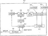
Fig. 2 is the block diagram of expression high frequency electric source.
Fig. 3 is the profile of the fore-end of expression resectoscope.
Fig. 4 is the structure chart of electrode device.
Fig. 5 is the enlarged drawing of the fore-end of expression electrode device.
Fig. 6 is the flow chart of the control flow of expression high intensity light source.
Fig. 7 is the enlarged drawing of effect that is used to illustrate the leading section of resectoscope.
Fig. 8 is the figure that is used to illustrate the front end electrode part of the fore-end that is arranged on the electrode device.
Fig. 9 is the figure that is used to illustrate the front end electrode part of the fore-end that is arranged on the electrode device.
Figure 10 is the figure that is used to illustrate the front end electrode part of the fore-end that is arranged on the electrode device.
Figure 11 is the figure that is used to illustrate the front end electrode part of the fore-end that is arranged on the electrode device.
Figure 12 is the figure that is used to illustrate the front end electrode part of the fore-end that is arranged on the electrode device.
Figure 13 is the figure that is used to illustrate the front end electrode part of the fore-end that is arranged on the electrode device.
Figure 14 is the structure chart that comprises the high-frequency treatment device of the resectoscope in the past that uses the normal saline infusion liquid.
Figure 15 is the figure that represents electrode in the past.
Figure 16 is a key diagram of representing near the state the electrode of resectoscope in the past.
The specific embodiment
Below, with reference to Fig. 1~Fig. 7 embodiments of the present invention are described.
Fig. 1~Fig. 7 relates to first embodiment of the present invention, Fig. 1 is the overall structure figure of high-frequency treatment device, Fig. 2 is the block diagram of expression high frequency electric source, Fig. 3 is the profile of the fore-end of expression resectoscope, Fig. 4 is the structure chart of electrode device, Fig. 5 is the enlarged drawing of the fore-end of expression electrode device, and Fig. 6 is the flow chart of the control flow of expression high intensity light source, and Fig. 7 is the enlarged drawing of effect that is used to illustrate the leading section of resectoscope.
As shown in Figure 1, as the resectoscope 1 of high-frequency treatment device mainly by constituting with the lower part: the sleeve pipe 2 of thin tube-like; Be located at the operating portion 3 of the rear end of this sleeve pipe 2; Insert the optic visual tube of observing in the sleeve pipe 24 from this operating portion 3; High intensity light source 21 as high-frequency generation means; With electrode device 5, it is passed to the high frequency electric from this high intensity light source 21, and biological tissue is disposed.
Sleeve pipe 2 is inserted subject inside from urethra, vagina etc.This sleeve pipe 2 comprises the main part 7 of electric conductivity insertion section 6 with leading section 6a and the rear end of being located at this insertion section 6.Be provided with water delivery nozzle 8 and valve 9 on this main part 7, this water delivery nozzle 8 is used for carrying infusion liquid by 6 inside, insertion section in body cavity, is in the present embodiment to carry normal saline.Water delivery nozzle 8 can be connected with tube for transfusion 12 on disassembled and assembled freely ground, and this tube for transfusion 12 is used to provide the normal saline 11 that is contained in the container 10.
On the other hand, operating portion 3 has: the operating portion main body 14 that can constitute on the disassembled and assembled freely ground, main part 7 rear end of sleeve pipe 2; At the outstanding axis of guide 15 that is provided with in the rear end of this operating portion main body 14; Can remain on the slide block 16 on this axis of guide 15 with being free to slide.
Be provided with block 17 in the rear end of the axis of guide 15.Between this block 17 and operating portion main body 14, slide block 16 freely reciprocatingly slides along the axis of guide 15.And the axis of guide 15 forms hollow structure inside.Optic visual tube 4 is inserted in the axis of guide 15 and is inserted in the sleeve pipe 2, and can be fastened on the block 17 disassembled and assembled freely.
On slide block 16, be provided with the maintaining part 18 that keeps electrode device 5, and be provided with the conducting parts 19 that is used for passing to high frequency electric to electrode device 5.This conducting parts 19 conducts with the adapter 20 that is located on the slide block 16, be arranged on high intensity light source 21 output cable 22 front ends output plug 23 detachables be fastened on the adapter 20.
Be connected with the foot switch 40 with switching pedal on this high intensity light source 21, this switching pedal is used to carry out operation and the output of control high frequency that counter electrode device 5 provides high frequency electric.In addition, extend the connected signal cable 42 of an end from the front of high intensity light source 21, the other end of this signal cable 42 is connected with the pipe clip valve (pitchvalve) 41 that is used to be connected container 10 and tube for transfusion 12.That is, pipe clip valve 41 is accepted the power supply supply by signal cable 42 from high intensity light source 21.
Constitute transfusion unit by these containers 10, tube for transfusion 12 and pipe clip valve 41.
And, on block 17, be provided with ring-type placement section 24, so that user is placed the thumb of hands.On the other hand, on slide block 16, be provided with shaft-like placement section 25 so that user is placed the forefinger, middle finger of hands and nameless or place forefinger to little finger of toe, these placement sections 24 and placement section 25 by elastic joint 26 to the arrow H direction application of force and be connected.
And when these placement sections 24,25 of operation, when operating portion main body 14 directions (the place ahead to) were slided, the front end electrode part 27 of electrode device 5 was outstanding from the front end of sleeve pipe 2 along the axis of guide 15 for slide block 16.Otherwise to block direction (rear to) operation slide block 16 time, the front end electrode part 27 of electrode device 5 is incorporated among the leading section 6a of sleeve pipe 2.
Visual 29 of the rear end that optic visual tube 4 comprises the insertion section 28 of inserting in the sleeve pipe 2, be located at this insertion section 28.This visual 29 near be provided with optical connector 33, can be connected and fixed the adapter 32 of the photoconduction cable 31 that is connected with light supply apparatus 30 thereon disassembled and assembled freely.
Be sent to optical connector 33 from the illumination light of light supply apparatus 30 outputs by optical cable 31, be sent to insertion section front end 35 and ejaculation by the light carrier bundle that is built in the insertion section 28 again.
As shown in Figure 2, constitute as the high intensity light source 21 of high-frequency generation means and have: control circuit 50; Power circuit 51; High frequency generation circuit 52; Waveform circuit 53; Output transformer 54; Current sensor 55; Voltage sensor 56; A/D converter 57 and pipe clip valve power supply 58.
Power circuit 51 output DCs stream.High frequency generation circuit 52 is converted to high frequency electric to the DC current from power circuit 51.Waveform circuit 53 is according to the control of control circuit 50, to the waveform of high frequency generation circuit 52 indication high frequency electrics.
Below, use Fig. 3~Fig. 5 explanation outstanding and be accommodated in electrode device 5 in the leading section 6a from the leading section 6a of the sleeve pipe 2 of resectoscope 1.
As shown in Figure 3, expose front end electrode part 27 from the leading section 6a of resectoscope 1 as the function portion of electrode device 5.Front end electrode part 27 bends to roughly L shape when observing from the side, so as easily with organize butt.As previously described, by operation placement section 24,25 (with reference to Fig. 1) and counter electrode device 5 is free to slide operation,, perhaps be received into basically in the leading section 6a so that it is forwards outstanding from the leading section 6a of resectoscope 1 to have a fore-end of front end electrode part 27.
As shown in Figure 4, the front side of electrode device 5 branches into two parts, and be provided with as apply electrode, form roughly that the metal wire of ring-type (closed loop) is a front end electrode part 27, it connects this two branch end respectively.In addition, the fore-end in the branch end of electrode device 5 is provided with the sheath 38 that is made of the 1st () insulant.
On this front end electrode part 27, in the part midway from the component of electrode device 5 to base end side, the guide barrel 5a that inserts the insertion section 28 of logical optic visual tube 4 is fixedly connected on the top when the paper of Fig. 4 is observed.Thus, electrode device 5 is being guided by the guide barrel 5a of the insertion section 28 of having inserted optic visual tube 4 and to advance by slide the time.
As shown in Figure 4 and Figure 5, to the lower side when paper is observed, two insulant (the 2nd insulant the present embodiment) 37 that the vertical direction side is extended, in preset range, cover front end electrode part 27 from the front end of sheath 38.Specifically, in each root portion that two fore-ends from the branch end of being located at electrode device 5 extend out, front end electrode part 27 is insulated material 37 respectively and is covered with in preset range.That is, two insulant 37 cover the root portion of the front end electrode part 27 less, that expose from sheath 38 front ends of usage frequency when coagulating etc. from excision, gasification, electricity at biological tissue respectively only in preset range.
This electrode device 5 is provided with sheath 38 and insulant 37, so that the front end electrode part 27 of metal wire becomes the contact site that contacts with the disposal area of body cavity, other metal wire partly becomes the noncontact portion that does not contact described disposal area.And the part that is covered by sheath 38 in the electrode device 5 becomes part 1, is becoming part 2 with the axial different side of this part 1 front end electrode part 27 upwardly extending, that root portion is bending section.Insulant 37 covers the bending section of the root portion of this front end electrode part 27.
Below, use Fig. 6 and Fig. 7 explanation action of the resectoscope of the present embodiment of formation as mentioned above.
At first, for example resectoscope 1 is inserted in patient's the body cavity from urethra, vagina etc.
As shown in Figure 6, trample, connect the switch pedal (S1) of foot switch 40, control circuit 50 control pipe clip valve power supplys 58 provide power supply to pipe clip valve 41, temporarily stop to carry normal saline (S2) by tube for transfusion 12.Then, control circuit 50 control high frequency generation circuit 52 begin to provide high frequency output (S3).
At this moment because the conveying of normal saline stops, so pro-termination electrode portion 27 near accumulate the normal saline that is heated by high frequency electric, be easy to generate bubble.And by temporarily stopping to carry normal saline, the bubble that is produced can not disperse when transfusion.And as shown in Figure 7, the high frequency electric that offers front end electrode part 27 flows to as the insertion section 6 of returning side from the part as the front end electrode part 27 contact biological tissues that apply side.Thus, the tissue of contact front end electrode part 27 is implemented excision, gasification and electricity and coagulates etc.
And the root portion of front end electrode part 27 is insulated material 37 and covers, so the surface area of front end electrode part 27 and contact with normal saline can carry out the intensification of normal saline more effectively less than in the past electrode 912 (with reference to Figure 15).Therefore, around the front end electrode part of exposing 27, be easy to generate bubble.
Then, in step S4, control circuit 50 is taken into the current value of current sensor 55 by A/D converter 57, then is taken into the magnitude of voltage of voltage sensor 56 in step S5 by A/D converter 57.
Then, control circuit 50 in circuit inside with the magnitude of voltage that is taken into divided by current value, calculate front end electrode part 27 thus and as the resistance Z between the insertion section 6 of trocar sheath.
Then, whether the resistance Z that calculates of control circuit 50 is less than for example judgement of 500 Ω (S7).Control circuit 50, returns step S4 and repeats identical processing during less than 500 Ω in the resistance Z that calculates.
On the other hand, if the resistance Z that calculates greater than 500 Ω, then entire front end electrode part 27 around surrounded by bubble, produced discharge, so do not need to stop the conveying of normal saline.Then, control circuit 50 stops to provide power supply (S8) to pipe clip valve 41, begins once more to carry normal saline near the forward end electrode part 27.
Then, when the switch pedal of foot switch 40 is released (S9), control circuit 50 control high frequency generation circuit 52 stop high frequency output (S10).
That is, according to above explanation, when the switch pedal of foot switch 40 was connected, termination electrode portion 27 produced bubble in the past.But, after the switch pedal of foot switch 40 just has been switched on, need the time because the temperature of normal saline rises, so pro-termination electrode portion 27 places less produce bubble.At this moment, be in the state of the resistance Z of tissue resistance less than 500 Ω, control circuit 50 provides power supply to pipe clip valve 41, stops near the conveying normal saline by tube for transfusion 12 forward end electrode part 27.
During through certain hour, increase attached to the bubble on the front end electrode part 27 after connecting the switch pedal of foot switch 40, resistance Z rises.When this resistance Z reaches 500 Ω, surrounded by bubble around the entire front end electrode part 27, be in the state that produces discharge, disconnect the power supply of pipe clip valve 41 is supplied with, begin near conveying normal saline once more by tube for transfusion 12 forward end electrode part 27.
Compare with the electrode 912 that the Resectoscopic device in the past 901 shown in Figure 14~Figure 16 has, the front end electrode part 27 of present embodiment is owing to covered insulant 37, form less area with the surface area of contact with normal saline, so can shorten the time that the intensification of normal saline needs.That is, the resectoscope 1 of present embodiment constitutes and can shorten behind the switch pedal of connecting foot switch 40, to producing the time that covers entire front end electrode part 27 bubble on every side.
Therefore, the resectoscope 1 of present embodiment can obtain power saving effect by shortening from the time of high intensity light source 21 output high frequency electrics, and is easy to generate the bubble around the covering entire front end electrode part 27.
In addition, near the bubbles the front end electrode part 27 can not make its discharge so can cover entire front end electrode part 27 with less power utilization bubble owing to transfusion is dispersed, and excision, gasification, the electricity that can carry out biological tissue coagulates etc.
As a result, low power high intensity light source 21 can be used, manufacturing cost can be reduced as the resectoscope 1 of high-frequency treatment device, and power saving.
In addition, front end electrode part 27 is in order to compare the contact area of dwindling with normal saline with electrode 912 (with reference to Figure 15) in the past, when excising, gasify, electricity coagulates etc., can replace covering the insulant 37 of the root portion of usage frequency front end electrode part 27 less, that expose from the front end of sheath 38, and constitute Fig. 8~structure shown in Figure 13.
As shown in Figure 8, the outer surface for the root portion of exposing from sheath 38 front ends (bending section) of front end electrode part 27 applies the insulating coating 27a as the 2nd insulant of non-conductive film in preset range.Thus, front end electrode part 27 has been dwindled the contact area with normal saline.
As shown in Figure 9, front end electrode part 27 makes the fore-end of conduct the 2nd insulant of sheath 38 extend out along bearing of trend, covers the outer surface of root portion (bending section) in preset range.Thus, front end electrode part 27 dwindle and normal saline between contact area.In Fig. 9, the fore-end of sheath 38 forms the roughly L shape of vertical direction bending downwards when observing from the side.
As shown in figure 10, pro-termination electrode portion 27 is provided with the coiled pipe 38a (the 2nd insulant in the present embodiment) of the Periostracum Serpentis shape that is made of insulant, thereby can freely change desired coverage the outer surface of the root portion of exposing from sheath 38 front ends (bending section).Thus, user such as doctor can reduce the contact area between front end electrode part 27 and the normal saline in desired scope.
According to the structure of the front end electrode part 27 of Fig. 8 of above explanation~shown in Figure 10, the needed time of intensification that can suppress normal saline, easily pro-termination electrode portion 27 around produce bubble.And, because the area that the outer surface of front end electrode part 27 exposes is less, so can be by of the discharge of less bubble generation the past termination electrode portion 27 to insertion section 6.
In addition, according to the structure of front end electrode part 27 shown in Figure 10, user such as doctor can suitably be selected the scope that front end electrode part 27 is exposed according to the situation of the affected part that will treat.
Front end electrode part 27 shown in Figure 11 forms the external diameter that makes the highest 27c of annular center portion of the usage frequency external diameter less than the root portion of exposing from sheath 38 front ends.The external diameter of this central part 27c attenuates, so the contact area between central part 27c and the normal saline reduces.Therefore, the amount of the bubble around the covering central part 27c gets final product on a small quantity.
Front end electrode part shown in Figure 12 27 is utilized the principle identical with front end electrode part shown in Figure 11 27, has a plurality of notch part 27b on the one side of face forward side.Contact area between notch part 27b and the normal saline reduces.Therefore, the amount of the bubble around the covering notch part 27b gets final product on a small quantity.
In addition, as shown in figure 13, front end electrode part 27 is draw out annular (closed loop) tabular, and side has a plurality of notch part 27B forwardly, also can obtain identical effect.In addition, the root portion of this tabular front end electrode part 27 is applied above-mentioned insulating coating 27a as the 2nd insulant.
The front end electrode part 27 of the resectoscope 1 of above-described present embodiment is under a spot of bubble generation during contact tissue, produce discharge between itself and the insertion section 6 effectively, so can reduce the power consumption of high intensity light source 21, can realize the small-powerization of employed high frequency power.Therefore, do not need to use and can export powerful expensive high-frequency supply unit 21, can use pro-termination electrode portion 27 with organize can export with small-power when contacting, at short notice to that discharge, the cheap high intensity light source 21 in insertion section 6.
In addition,, can shorten the needed time of discharge, can suppress operating time, also can alleviate patient's burden according to the resectoscope 1 of present embodiment.
In addition, the invention is not restricted to the embodiment of above narration, can carry out various distortion without departing from the spirit and scope of the present invention and implement.
Claims (7)
1. a high-frequency treatment device is characterized in that, this high-frequency treatment device possesses:
Produce the high-frequency generation means of high frequency electric;
The electrode device, it is electrically connected with this high-frequency generation means, and front end has and applies electrode to what described high frequency electric discharged, and this base end side that applies electrode is covered by the 1st insulant;
As from the described insertion section of returning side that applies the described high frequency electric of electrode, it is taken in this electrode device and this electrode device can be moved freely on predetermined direction;
Transfusion unit, it is transported near described applying the electrode by this insertion section with infusion liquid; And
The 2nd insulant, it is formed by the telescopic material that can freely change its coverage, at the described root portion that applies electrode that the front end from described the 1st insulant exposes, the 2nd insulant applies electrode, covers this apply the outer surface of electrode in preset range along this from the 1st insulant.
2. high-frequency treatment device according to claim 1, it is characterized in that, the described electrode that applies forms ring-type at the fore-end of described electrode device, and the external diameter that forms described cyclic middle body forms the external diameter of the root portion of exposing less than the front end from described the 1st insulant.
3. high-frequency treatment device according to claim 1 is characterized in that, the described electrode that applies has the contact site and the noncontact portion that is connected with described the 1st insulant that contacts with the desired disposal area of subject,
At least a portion of this noncontact portion is covered by the 2nd insulant in described preset range, and insulate with described subject.
4. high-frequency treatment device according to claim 3, it is characterized in that, the described electrode that applies is the closed loop with leading section and base end part, and the described electrode that applies has: the part 1 that is provided with described the 1st insulant that extends from the described base end part forward end direction that applies electrode; And upwardly extendingly in the side different comprise the described part 2 that applies the leading section of electrode with described part 1.
5. high-frequency treatment device according to claim 4 is characterized in that, this high-frequency treatment device also has the bending section that engages described part 1 and described part 2.
6. high-frequency treatment device according to claim 5 is characterized in that, described bending section is covered by described the 2nd insulant.
7. high-frequency treatment device according to claim 3 is characterized in that, the described electrode that applies has not function portion and is used for described subject is implemented the predetermined function portion that disposes, and at least a portion of described not function portion insulate with described subject.
Applications Claiming Priority (2)
| Application Number | Priority Date | Filing Date | Title |
|---|---|---|---|
| JP2004292955 | 2004-10-05 | ||
| JP292955/2004 | 2004-10-05 |
Publications (2)
| Publication Number | Publication Date |
|---|---|
| CN101035478A CN101035478A (en) | 2007-09-12 |
| CN100558309C true CN100558309C (en) | 2009-11-11 |
Family
ID=36142718
Family Applications (1)
| Application Number | Title | Priority Date | Filing Date |
|---|---|---|---|
| CNB2005800339880A Expired - Fee Related CN100558309C (en) | 2004-10-05 | 2005-10-05 | High-frequency treatment device |
Country Status (5)
| Country | Link |
|---|---|
| US (1) | US7867229B2 (en) |
| EP (1) | EP1797837A4 (en) |
| JP (1) | JP4675329B2 (en) |
| CN (1) | CN100558309C (en) |
| WO (1) | WO2006038646A1 (en) |
Families Citing this family (10)
| Publication number | Priority date | Publication date | Assignee | Title |
|---|---|---|---|---|
| US20080275444A1 (en) * | 2007-05-02 | 2008-11-06 | Olympus Medical Systems Corp. | Endoscopic treatment instrument and tissue incision method |
| GB2492325B (en) * | 2011-06-23 | 2016-06-22 | Gyrus Medical Ltd | Electrosurgical electrode |
| CN102846375B (en) * | 2012-08-16 | 2016-02-03 | 珠海市司迈科技有限公司 | Resectoscope bipolar electrode |
| CN104546119A (en) * | 2015-01-05 | 2015-04-29 | 张建国 | Mucous membrane detacher |
| CN104921804B (en) * | 2015-06-24 | 2018-02-06 | 珠海市司迈科技有限公司 | Left and right shunt circuit bipolar electrode |
| USD861163S1 (en) * | 2017-08-04 | 2019-09-24 | Olympus Winter & Ibe Gmbh | Part of medical instrument |
| WO2019071269A2 (en) | 2017-10-06 | 2019-04-11 | Powell Charles Lee | System and method to treat obstructive sleep apnea |
| DE102018113835A1 (en) * | 2018-06-11 | 2019-12-12 | Olympus Winter & Ibe Gmbh | Assembly aid for attaching electrodes in a resectoscope |
| WO2020202285A1 (en) * | 2019-03-29 | 2020-10-08 | オリンパス株式会社 | Electrode unit and resectoscope device |
| DE102020108614A1 (en) | 2020-03-27 | 2021-09-30 | Olympus Winter & Ibe Gmbh | Electrosurgery generator, electrosurgical system and method for operating an electrosurgery generator |
Citations (1)
| Publication number | Priority date | Publication date | Assignee | Title |
|---|---|---|---|---|
| US3939839A (en) * | 1974-06-26 | 1976-02-24 | American Cystoscope Makers, Inc. | Resectoscope and electrode therefor |
Family Cites Families (16)
| Publication number | Priority date | Publication date | Assignee | Title |
|---|---|---|---|---|
| DE3603758A1 (en) * | 1985-02-09 | 1986-08-14 | Olympus Optical Co., Ltd., Tokio/Tokyo | RESECTOSCOPE DEVICE |
| US5080660A (en) * | 1990-05-11 | 1992-01-14 | Applied Urology, Inc. | Electrosurgical electrode |
| US5902272A (en) * | 1992-01-07 | 1999-05-11 | Arthrocare Corporation | Planar ablation probe and method for electrosurgical cutting and ablation |
| US5683366A (en) * | 1992-01-07 | 1997-11-04 | Arthrocare Corporation | System and method for electrosurgical tissue canalization |
| US5569244A (en) * | 1995-04-20 | 1996-10-29 | Symbiosis Corporation | Loop electrodes for electrocautery probes for use with a resectoscope |
| JPH09262244A (en) * | 1996-01-24 | 1997-10-07 | Olympus Optical Co Ltd | Resectoscope |
| US5749870A (en) * | 1996-08-23 | 1998-05-12 | Nebl, Inc. | Electrode for coagulation and resection |
| US5919190A (en) * | 1996-12-20 | 1999-07-06 | Vandusseldorp; Gregg A. | Cutting loop for an electrocautery probe |
| US6494881B1 (en) | 1997-09-30 | 2002-12-17 | Scimed Life Systems, Inc. | Apparatus and method for electrode-surgical tissue removal having a selectively insulated electrode |
| JP3802698B2 (en) * | 1999-01-14 | 2006-07-26 | オリンパス株式会社 | Receptoscope device |
| JP3782622B2 (en) * | 1999-09-30 | 2006-06-07 | オリンパス株式会社 | Reject electrode |
| US6929643B2 (en) | 2002-04-15 | 2005-08-16 | Olympus Corporation | Resectoscope apparatus and electric operation apparatus |
| JP3791911B2 (en) * | 2002-04-15 | 2006-06-28 | オリンパス株式会社 | Receptoscope device |
| US6918907B2 (en) * | 2003-03-13 | 2005-07-19 | Boston Scientific Scimed, Inc. | Surface electrode multiple mode operation |
| US6939348B2 (en) * | 2003-03-27 | 2005-09-06 | Cierra, Inc. | Energy based devices and methods for treatment of patent foramen ovale |
| US7662151B2 (en) * | 2006-02-15 | 2010-02-16 | Boston Scientific Scimed, Inc. | Contact sensitive probes |
-
2005
- 2005-10-05 JP JP2006539312A patent/JP4675329B2/en not_active Expired - Fee Related
- 2005-10-05 CN CNB2005800339880A patent/CN100558309C/en not_active Expired - Fee Related
- 2005-10-05 WO PCT/JP2005/018422 patent/WO2006038646A1/en active Application Filing
- 2005-10-05 EP EP05790546A patent/EP1797837A4/en not_active Withdrawn
-
2006
- 2006-11-17 US US11/601,183 patent/US7867229B2/en not_active Expired - Fee Related
Patent Citations (1)
| Publication number | Priority date | Publication date | Assignee | Title |
|---|---|---|---|---|
| US3939839A (en) * | 1974-06-26 | 1976-02-24 | American Cystoscope Makers, Inc. | Resectoscope and electrode therefor |
Also Published As
| Publication number | Publication date |
|---|---|
| WO2006038646A1 (en) | 2006-04-13 |
| JPWO2006038646A1 (en) | 2008-05-15 |
| US7867229B2 (en) | 2011-01-11 |
| CN101035478A (en) | 2007-09-12 |
| EP1797837A1 (en) | 2007-06-20 |
| US20070066976A1 (en) | 2007-03-22 |
| EP1797837A4 (en) | 2008-11-26 |
| JP4675329B2 (en) | 2011-04-20 |
Similar Documents
| Publication | Publication Date | Title |
|---|---|---|
| CN100558309C (en) | High-frequency treatment device | |
| US4936301A (en) | Electrosurgical method using an electrically conductive fluid | |
| US4943290A (en) | Electrolyte purging electrode tip | |
| US7682359B2 (en) | High-frequency treatment apparatus | |
| US8771266B2 (en) | Ablation therapeutic device, resectoscope and method of ablating living body tissue | |
| US7195630B2 (en) | Converting cutting and coagulating electrosurgical device and method | |
| US6210405B1 (en) | Under water treatment | |
| US20140180279A1 (en) | Cool-tip thermocouple including two-piece hub | |
| CN108472073A (en) | Electrosurgery unit with multiple monopolar electrode components | |
| WO1994026186B1 (en) | Medical probe with stylets | |
| US20100160910A1 (en) | Electrosurgical tool | |
| US20040082938A1 (en) | Resectoscope apparatus | |
| CN100558310C (en) | High-frequency treatment device | |
| JP3938707B2 (en) | Electrosurgical equipment | |
| US7060065B2 (en) | Resectscope apparatus | |
| JP3791911B2 (en) | Receptoscope device | |
| US6328734B1 (en) | Flexible endoscope with bipolar return electrode and working channel | |
| CN216628687U (en) | Circular contact of medicine electrothermal absorption | |
| JP3837082B2 (en) | Receptoscope device | |
| JP2004188023A (en) | Resectoscope apparatus | |
| US20080065063A1 (en) | High-frequency endoscopic instrument | |
| GB2362829A (en) | Resectoscope with sliding bi-polar loop electrodes | |
| JP2003299671A (en) | Resectoscope device | |
| CN2446971Y (en) | Ophthalmic microwave transmitter | |
| WO2023026098A1 (en) | Flexible telescopic shaft for monopolar electrosurgical pencil |
Legal Events
| Date | Code | Title | Description |
|---|---|---|---|
| C06 | Publication | ||
| PB01 | Publication | ||
| C10 | Entry into substantive examination | ||
| SE01 | Entry into force of request for substantive examination | ||
| C14 | Grant of patent or utility model | ||
| GR01 | Patent grant | ||
| CF01 | Termination of patent right due to non-payment of annual fee |
Granted publication date: 20091111 |
|
| CF01 | Termination of patent right due to non-payment of annual fee |