CN100584039C - Method for post-processing a 3D digital video signal - Google Patents
Method for post-processing a 3D digital video signal Download PDFInfo
- Publication number
- CN100584039C CN100584039C CN200380101874A CN200380101874A CN100584039C CN 100584039 C CN100584039 C CN 100584039C CN 200380101874 A CN200380101874 A CN 200380101874A CN 200380101874 A CN200380101874 A CN 200380101874A CN 100584039 C CN100584039 C CN 100584039C
- Authority
- CN
- China
- Prior art keywords
- pixel
- disparity map
- projected
- digital video
- post
- Prior art date
- Legal status (The legal status is an assumption and is not a legal conclusion. Google has not performed a legal analysis and makes no representation as to the accuracy of the status listed.)
- Expired - Fee Related
Links
Images


Classifications
-
- H—ELECTRICITY
- H04—ELECTRIC COMMUNICATION TECHNIQUE
- H04N—PICTORIAL COMMUNICATION, e.g. TELEVISION
- H04N13/00—Stereoscopic video systems; Multi-view video systems; Details thereof
-
- H—ELECTRICITY
- H04—ELECTRIC COMMUNICATION TECHNIQUE
- H04N—PICTORIAL COMMUNICATION, e.g. TELEVISION
- H04N19/00—Methods or arrangements for coding, decoding, compressing or decompressing digital video signals
- H04N19/50—Methods or arrangements for coding, decoding, compressing or decompressing digital video signals using predictive coding
- H04N19/597—Methods or arrangements for coding, decoding, compressing or decompressing digital video signals using predictive coding specially adapted for multi-view video sequence encoding
-
- G—PHYSICS
- G06—COMPUTING; CALCULATING OR COUNTING
- G06T—IMAGE DATA PROCESSING OR GENERATION, IN GENERAL
- G06T7/00—Image analysis
- G06T7/50—Depth or shape recovery
- G06T7/55—Depth or shape recovery from multiple images
-
- G—PHYSICS
- G06—COMPUTING; CALCULATING OR COUNTING
- G06T—IMAGE DATA PROCESSING OR GENERATION, IN GENERAL
- G06T7/00—Image analysis
- G06T7/50—Depth or shape recovery
- G06T7/55—Depth or shape recovery from multiple images
- G06T7/593—Depth or shape recovery from multiple images from stereo images
-
- H—ELECTRICITY
- H04—ELECTRIC COMMUNICATION TECHNIQUE
- H04N—PICTORIAL COMMUNICATION, e.g. TELEVISION
- H04N13/00—Stereoscopic video systems; Multi-view video systems; Details thereof
- H04N13/10—Processing, recording or transmission of stereoscopic or multi-view image signals
-
- H—ELECTRICITY
- H04—ELECTRIC COMMUNICATION TECHNIQUE
- H04N—PICTORIAL COMMUNICATION, e.g. TELEVISION
- H04N13/00—Stereoscopic video systems; Multi-view video systems; Details thereof
- H04N13/10—Processing, recording or transmission of stereoscopic or multi-view image signals
- H04N13/106—Processing image signals
- H04N13/111—Transformation of image signals corresponding to virtual viewpoints, e.g. spatial image interpolation
-
- H—ELECTRICITY
- H04—ELECTRIC COMMUNICATION TECHNIQUE
- H04N—PICTORIAL COMMUNICATION, e.g. TELEVISION
- H04N13/00—Stereoscopic video systems; Multi-view video systems; Details thereof
- H04N13/10—Processing, recording or transmission of stereoscopic or multi-view image signals
- H04N13/106—Processing image signals
- H04N13/122—Improving the 3D impression of stereoscopic images by modifying image signal contents, e.g. by filtering or adding monoscopic depth cues
-
- H—ELECTRICITY
- H04—ELECTRIC COMMUNICATION TECHNIQUE
- H04N—PICTORIAL COMMUNICATION, e.g. TELEVISION
- H04N13/00—Stereoscopic video systems; Multi-view video systems; Details thereof
- H04N13/10—Processing, recording or transmission of stereoscopic or multi-view image signals
- H04N13/106—Processing image signals
- H04N13/128—Adjusting depth or disparity
-
- G—PHYSICS
- G06—COMPUTING; CALCULATING OR COUNTING
- G06T—IMAGE DATA PROCESSING OR GENERATION, IN GENERAL
- G06T2200/00—Indexing scheme for image data processing or generation, in general
- G06T2200/04—Indexing scheme for image data processing or generation, in general involving 3D image data
Abstract
The present invention relates to a method for post-processing a 3D digital video signal, said digital video signal having a plurality of views with associated disparity maps. The invention is characterized in that said method comprises a first step of generating a projected disparity map from an original disparity map, and a second step of filling holes within said projected disparity map, the first step comprising the sub-step of removing isolated projected pixels on said projected disparity map by filtering them.
Description
Invention field
The present invention relates to a kind of post-processing approach of digital video signal, described digital video signal has a plurality of views that have the disparity map (disparity map) that is associated.
Described method for example can be used for the video communication system of the 3D Video Applications in the mpeg standard.
Background of invention
Most of 3D vision signals represent that (being called the 3D scene) depends on depth map and disparity map.Usually, from one group of image (described image is corresponding to different points of observation) of given 3D scene, each width of cloth image may have the different characteristics that is associated, for example depth map and texture.The depth map of a point of observation is a gray level image, and its each pixel covers the distance of the video camera of taking this scene.When a New Observer point that will generate scene when (being called view more simply), if the parameter (displacement of the variation that provides other point of observation, its depth map, intrinsic camera parameters and when this point of observation moves to New Observer point, experienced when video camera, rotation, shot change), just may calculate some zone of New Observer point.This process is called " reconstruction ", and the New Observer point of being created is called reconstructed view (or reconstructed image).If 1 P in the scene can see from two points of observation, can obtain this pixel coordinate in New Observer point from this pixel coordinate raw observation point by a conversion vector (translationvector) so.These vectors are called difference vector." three dimensionalcomputer vision (3D computer vision)-O.Faugeras MIT Press 1993 " is disclosed as document, and perspective geometry result sets up a simple relation between the depth value of the difference vector of disparity map and depth map.
In the transmission of video signals process, many views well known to those skilled in the art or D encoding scheme generally cover the needed texture of point of observation particular range by compression and depth map is encoded.Though texture can be encoded with standard method (this will cause known illusion problem potentially under the situation of lossy coding), the degree of depth (or parallax) coding is then more complicated: for an encoded depth map, have a contract drawing visually similar to original depth-map (aspect) and not mean that it must have same reconstruction attribute.In new view generative process, point or zone may be switched to wrong position (because wrong difference vector).This will produce may be more discontinuous than the more obvious texture of " vision " contract drawing that code pattern proposed.And intensive depth map is very large file, if want that the size Control of depth map at reasonable range (just less than texture bit rate 20%), then lossy compression method almost is inevitable.Therefore illusion and unsuitable depth/disparity values must be handled, and reprocessing and enhancement algorithms behind the decoded video signal must be designed.
In the MPEG-4 standard, depth map can encode with many accessories instrument (MAC) (referring to document "
Amendment 1:Visual extensions, ISO/IEC JTC1/SC29/WG 11 N 3056, December 1999 "), wherein on the basis of piece, depth map being carried out the DCT coding, this is similar to classical luminance picture coding well known to those skilled in the art.Do not mention concrete processing, but as previously mentioned, traditional MPEG instrument helps texture to potential illusion, then so uninevitable for depth map.Therefore, for example in texture reconstructed image, this may cause the fuzzy edge that together occurs together with isolated texture pixel, and in addition, these two kinds of effects are inconsistent in time during point of observation thereafter.
Goal of the invention and summary
Therefore, one object of the present invention is to provide a kind of post-processing approach of digital video signal, and described digital video signal has a plurality of views that have the disparity map that is associated, the coding illusion that described method can CD figure (or disparity map).
For achieving the above object, provide a kind of the method for claim 1.
As will at length seeing, by removing isolated projected pixel, the inconsistent value in projection and the original disparity map has been eliminated.
The step that comprises claim 2 according to one embodiment of the method for the invention and limited.
The step that comprises claim 3 according to a further embodiment of the method according to the invention and limited.
The step that comprises claim 4 according to a further embodiment of the method according to the invention and limited.
The step that comprises claim 5 according to a further embodiment of the method according to the invention and limited.
The step that comprises claim 6 according to a further embodiment of the method according to the invention and limited.
By considering the projected pixel around the border, hole, the improper value that helps avoiding being used for being freed from the hole boundary value of the mistake that compression causes is filled described hole.
The step that comprises claim 7 according to a further embodiment of the method according to the invention and limited.
This helps being avoided the interpolation for inconsistent undefined value on the space.
The accompanying drawing summary
By reading the detailed description carry out with reference to the accompanying drawings, above-mentioned and other purposes, characteristics and advantage of the present invention will become apparent, wherein:
Fig. 1 is the schematic diagram according to vision signal post-processing approach of the present invention;
Fig. 2 has drawn some holes in the disparity map of projection, and these holes are that first step by the vision signal post-processing approach of Fig. 1 produces;
Fig. 3 has drawn in first step of the vision signal post-processing approach of Fig. 1, the process in the hole in the disparity map of filtration projection;
Fig. 4 shows in second step of the vision signal post-processing approach of Fig. 1, the process in the hole in the disparity map of filling projection; And
Fig. 5 shows in the 3rd step of the vision signal post-processing approach of Fig. 1, the process of filtering undefined pixel value.
To adopt corresponding Reference numeral for same unit in the specification full text.
Detailed description of the invention
In the following description, function well known to those skilled in the art or structure will not be described in detail, in order to avoid allow unnecessary details blur the present invention.
The present invention relates to a kind of post-processing approach of digital video signal.
Described method can be used in the video communication system of the 3D Video Applications that is used for MPEG4.
A 3D vision signal comprises a plurality of points of observation, and it has the different characteristics that is associated, for example shape, texture, motion vector, disparity map, depth map, color or the like.
When vision signal of transmission, encode to it.In cataloged procedure, its different characteristic is used compression algorithm with compression algorithm coding, especially disparity map and depth map and is encoded.This compression may cause having the impaired disparity map and the depth map of illusion.
Will decode to it after the video signal transmission, all then views are rebuilt in the algorithm that comprises reprocessing decoding parallax.In the time will generating New Observer point of scene, if the parameter (displacement of the variation that provides other point of observation, its depth map, intrinsic camera parameters and when this point of observation moves to New Observer point, experienced when video camera, rotation, shot change), just may calculate some zone of New Observer point.
Post-processing approach is based on such fact: when when another view and impaired depth map thereof are rebuild a new view, sample as will be described further, depth map experiences some conversion (for example projection), the problematic value of easier detection when making than use original decoded figure.
At first, owing to have this fact of corresponding relation (perspective geometry) between the degree of depth and the parallax, we consider disparity map.Because it is (for example well known to those skilled in the art and describe in document " O.Faugeras; Three-dimensionalcomputer vision (3D computer vision); MIT Press; 1993 " always might to have all difference vector along same direction, by adjust according to copolar (epipolar) constraint original solid to), we look squarely difference vector (the common situation of " parallel three-dimensional the setting " of video cameras) with water and illustrate this method.Certainly, this never is a limitation of the present invention.In this case, difference vector is defined by single numerical value, therefore, is called " parallax value " when below mentioning.
Hereinafter, I
OExpression original texture image, I
NRepresent the view of new reconstruction, d represents disparity map, d (x, y) remarked pixel (x, the parallax value of y) locating.New view is positioned at the left side or the right side of original view and has this fact of specific baseline (more or less away from original view), will be represented by factor alpha.For each pixel in the view (x y), has following relationship:
I
O(x,y)=I
N(x+α.d(x,y),y)
Process of reconstruction can be finished in several modes, common a kind of mode is (referring to document " Disparity field and depth map coding for multi-view 3D imagegeneration ", by D.Tzovaras, N.Grammalidis, G.Strinzis, SignalProcessing:Image Communication II (1998) 205-230 page or leaf) can be divided into following key step, will describe in detail below:
1. projected disparity map generalization
2. the filling in the hole on the projected disparity map
3. the projected disparity map after filling based on the hole generates final I
NView
On the basis of process of reconstruction, finish the reprocessing of point of observation as follows and as shown in Figure 1.
At first step 1), generate projected disparity map from the original disparity map of a point of observation.N on a view pixel is projected on the pixel of following view, and wherein N can get arbitrary value:
-get 0, if there is not pixel to be projected, the respective pixel of reconstructed view is arranged in the part (shaded areas) that new view is covered by original view in the case,
-get 1, if having only (or more a plurality of) pixel to be projected on this pixel, some pixel that this means original view has they is projected to parallax value on the same pixel on the reconstructed view.
Therefore, the tabulation of parallax value is corresponding with this pixel of following view.These tabulation groups corresponding with each pixel on the reconstructed view are exactly projected disparity map.
Main thought of the present invention is that along with the continuation of projection process, projected disparity map should have more or less identical with original graph systematicness.This means that also then projected disparity map also has same scrambling if original disparity map has some scramblings.
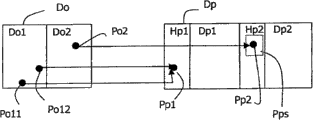
If consider to project to counting on each pixel, also should have certain systematicness.Especially, the centre in the hole, isolated projected pixel does not have.In a single day yet owing to be used for the DCT quantizing process of disparity map coding, some pixel value has changed, and is projected, they no longer approach its original surrounding pixel.These pixels are called isolated projected pixel.As shown in Figure 2, original disparity map Do has two pixel region do1 and do2 that its value is identical.Projected disparity map Dp also has the pixel region dp1 and the dp2 of two correspondences, but has " hole " regional Hp1 and Hp2.
Because some artifacts of compression, some pixel may be projected on these bore regions mistakenly.These called isolated pixels.
Described post-processing approach is removed those isolated projected pixel by using the first filtration F1.In first non-restrictive example, filtration is performed as follows.For each the pixel Pp on the projected disparity map Dp, the number that is defined as those surrounding pixels Pps in hole is calculated (described notion " surrounding pixel " depends on application: it can be to be a square neighborhood at center, circular neighborhood, rectangular neighborhood with this pixel ...).If this outnumbers a certain threshold level T1, for example surpass half of the number of pixels be included in this neighborhood, this isolated pixel of then being considered is set as " hole ", and anyly on the original disparity map causes the pixel of this isolated pixel to be marked as " wrong disparity value ".
First embodiment as shown in Figure 3.The first erroneous pixel Po2 on the original disparity map Do, the isolated projected pixel Pp2 that on the region D p2 of projected disparity map Dp, has a correspondence.The isolated projected pixel Pp1 that second pixel Po11 on the original disparity map Do and the 3rd pixel Po12 have the same correspondence on the region D p1 that is positioned at projected disparity map Dp.Window in dotted line defines the surrounding pixel Pps (being defined as the hole here) of pixel Pp2, makes Pp2 become an isolated pixel.This point is set up too for Pp1.As a result, pixel Po11, Po12 and the Po2 on the original disparity map Do corresponding with Pp1 and Pp2 is set as " improper value " respectively.
It should be noted that above-mentioned filtration is fit to the Expected Results of quantification to disparity map very much, described quantification is a step of compression, also is one of reason that causes the illusion on the disparity map.Notice that disparity quantization errors will mainly occurs on the sharp-pointed edge of disparity map, it is regional uniformly that these edges have two gray scales that differ greatly being separated by straight line (mainly at the object bounds place).Be exactly that these zones generate big hole on projected disparity map, it is suitable for accurately locating described isolated " wrong disparity value ".
In second non-limiting example, filtration is performed as follows.With regard to the number of projected pixel value, it also is possible detecting improper value by other isolated pixel on the inspection perspective view.Described isolated projected pixel is exactly the inconsistent pixel of pixel characteristic around those and their.
For example, surrounded, so wherein may include at least one improper value if pixel that comprises 3 values comprises the pixel of 2 values.By this pixel value group and the pixel value group around it are compared, the improper value in the tabulation just can be detected.
Notice that the quantitative range of the value of a pixel is between 0 to n (n is decided by original disparity map) on the projected disparity map.Which kind of isolated pixel will be the needed precision of isolated pixels detection will determine to want to handle: by the isolated pixel that the hole surrounds, be pixel then with two or more values, and those pixels that included only the pixel encirclement of 1 value, the rest may be inferred.Situation about handling is many more, and the precision of disparity map is just high more, yet algorithm also just is computer intensive (computer-intensive) more.According to the kind of the application of being wanted, can between precision and efficient, trade off.
A kind of mode of improving this filter process is factor alpha to be got different values test, and by this test, can detect more improper value.Change factor alpha two kinds of different modes arranged:
● by changing its symbol, promptly change projecting direction: adopt this mode, the two sides of object can both be enhanced in a width of cloth view.For example,,, then filter the hole on the right side on described mountain,, then filter the hole in the left side on described mountain if do " left side " projection if do " right side " projection if a width of cloth view comprises a mountain.
● by changing its size, utilize bigger hole, can strengthen the parallax infringement and can detect some of them when hour significantly infringement inadequately of its size.
Note, will improve detection efficiency with different α value operation filters and still also increase complexity.The selection of the parallax value number of testing also depends on application.
In second step 2), fill the hole on the projected disparity map.
In process of reconstruction, following second step after projected disparity map generates is the hole of filling by interpolation on this disparity map.In general, the selection of interpolation type is so to consider, promptly in the view of in the end rebuilding, described hole corresponding with the thing that belongs to background rather than with foreground object corresponding (this is the prevailing situation of " actual life (real life) ").Provide an example below.In projected disparity domain, by a filling process, the parallax value on repeating hole border on the sliver in hole.Described filling process is to get from the near border parallax value of Kongzui, and fills the sliver in described hole with it.
In any case interpolation depends on the parallax value on border, hole very much.Problem is, when adopting (that is to say impaired) disparity map that compressed, the hole boundary value that is used for this filling process may obviously change owing to compression algorithm, therefore may be wrong, in addition, also change to shifting gears of another line from a line: so, filling process is carried out on the basis of these wrong values, and these improper values will propagate into the sliver in hole.Visually, this will produce " wearing and tearing edge (worn edge) " phenomenon alleged in the reconstructed view.
The method according to this invention, for the hole boundary value has adopted a kind of new specific posttreatment filter F2, it can avoid the problems referred to above.Described filter application is in the border rather than the hole itself in hole.
At first, because in fact do not attend the meeting greatly and cause manifest error interpolated value (for example, the hole that pixel is wide) in some hole, therefore only carry out filtration at the boundary greater than the hole of given (depending on application) threshold value T2, for example, T2 is 3 pixels.
Then, for these hole H that chooses, the projected pixel value (not comprising the hole certainly) around considering is carried out median filter, as shown in Figure 4 on border pixel values.
In the example of Fig. 4, projected disparity map Dp comprises two zones; One is classified as pixel P, and another is classified as hole H.
Select the hole H1 on the projected disparity map Dp.Center on the border pixel values Vk1 of the hole H1 that is thought, a window W of selected pixels value (not being the hole).In case all pixel values among the window W all are sorted, and just can obtain intermediate value, and replace border pixel values Vk1 with it.
After changing pixel value Vk1, originally carry out conventional filling process with new pixel value Vk1 on one's body at hole H1 by median filter.
If this median filter causes change in boundary pixel value, original disparity map boundary pixel value correspondingly is labeled as improper value so, and to just being projected to the new value Vk1 of pixel assignment on the original disparity map on the boundary pixel of hole H1 if assigned new value Vk1.Make these modifications in the time of also can using the different value (changing its symbol or size as described above like that) of α.
For example, a boundary pixel in the selected hole on the projected disparity map Dp has pixel number 11, and its value is 10.The pixel of the correspondence on original disparity map Do is a pixel number 1, and its value is 10.Boundary pixel number 11 is through after the median filter, and its new value is 5.Therefore, the pixel number 1 of the correspondence on original disparity map Do obtains the value of " mistake ".In addition, to if the pixel of having been assigned on the original disparity map Do that new value 5 just should be mapped to boundary pixel number 11 is assigned value 5 newly.In fact, the pixel number on the original disparity map Do 6 has been assigned value 5.
At third step 3), preferably carry out last regularization.This is by median filter F3 projected disparity map to be carried out regularization on each bar line, and (this can make projected disparity rule more, and can be more level and smooth can not be by the detected scrambling of the filtration of front, such as since these irregular places be not positioned at big parallax be interrupted near thereby be not detected).As previously mentioned, possible variation all is switched on the original disparity map.
In the 4th step 4), the projected disparity map based on after the filling of hole generates final I
NView.
Above-mentioned different treatment step is carried out in projected disparity domain.Therefore, in first non-limiting example, as known to those skilled in the art, projected disparity map after the view R_VIEW of last reconstruction can be filtered by this generates, this is referring to document " Disparityfield and depth map coding for multi-view 3D image generation, byD.Tzovaras, N.ZGrammalidis; G.Strinzis, Signal Processing:ImageCommunication II (1998) 205-230 page or leaf ".
In second non-limiting example, reconstructed view is produced by the revision of original disparity map, and is as described below.
Attention is in step 1 and 2 different filter processes, as long as there is a pixel to be modified or to be labeled as " wrong disparity value " on projected disparity map, original disparity map also is labeled like that as described above and revises.Thereby the pixel of these modifications or mark is switched on the original disparity map.
So just obtained the tabulation of a undefined value WV or " wrong disparity value ".
In order to obtain the disparity map of final enhancing, in " hole filling " program, should replace this tabulation.The more reliable program of doing like this is the face content as follows.
Disparity map after scanning the original decoded with undefined value on each bar line that is to say amended original disparity map.In order to fill these undefined values, one of them of the border pixel values of copy undefined value: have two possible border pixel values candidates available usually, one on the left side of the pixel that comprises undefined value, and one on the right.A kind of selection is to adopt bilinearity or nearest-neighbor interpolation, but the different size in hole may cause spatially inconsistent of interpolation.Therefore, preferably select such boundary pixel, the value of this boundary pixel is near the value of the original pixels on the original decoded disparity map.Though compression may have bigger change to the value of original, uncompressed, but last value generally all more approaches the pixel around the same object, and reprocessed disparity map also approaches the disparity map (adopt the experimental result of this interpolation better) of original, uncompressed.
As shown in Figure 5, can see original decoded disparity map Dco and the amended original decoded disparity map Dcco that has undefined value.In a back disparity map Dcco, can see a undefined value WV1 that must proofread and correct.This value is corresponding with pixel Pco1 on the original decoded disparity map Dco.For undefined value WV1, the candidate has two boundary pixel Ps1 and a Ps2.The value of pixel Ps1 approaches the value of the original pixels Pco1 of the correspondence on the original decoded disparity map Dco most.Replace undefined value WV1 with described pixel Ps1.
In case finished interpolation, the disparity map after the correction has just generated, and this figure approaches the disparity map of original, uncompressed.The advantage of creating such figure has 2 points:
● it can reuse for the view process of reconstruction.Owing to eliminated illusion from the disparity map of this correction, can do final reconstruction (not needing to filter once more) with it except may in regularization step 3, needing.And it has provided a Billy with the better reconstructed view of projected disparity map.
● the figure after the correction that is generated is more sharp-pointed usually, and does not have exceptional value, and this makes it be more suitable for other the application based on depth/disparity values, synthetic and Z keying (Z-keying) for example well known in the art.
Need be appreciated that the present invention is not limited to above-mentioned embodiment, under the situation of the spirit and scope of the present invention that do not break away from appended claims and limited, can carry out various changes and modification.In this respect, make following conclusion.
Need be appreciated that the present invention is not limited to above-mentioned Video Applications.Can be used for also considering that compressed disparity maps comes any application of the system of processing signals.Especially, the present invention is applied to other mpeg standard families (MPEG-1, video compression algorithm MPEG-2) if be applied to disparity map coding, then also is applicable to ITU H26X family (H261, H263 and expansion, H261 is nearest now, reference number Q15-K-59).
Need be appreciated that, be not limited to above-mentioned implementation according to method of the present invention.
Have many kinds to realize the mode of the function of the method according to this invention, can rely on hardware branch or software item or by means of the two, wherein independent hardware or software item can be carried out a plurality of functions.This does not get rid of by software item or hardware branch or the combination of the two and finishes a function, therefore, does not need to revise the method for reprocessing vision signal of the present invention, just can form a single function.
Described software or hardware branch can be realized in many ways, for example pass through wired electronic circuits or the integrated circuit of suitably programming.Described integrated circuit can be included in computer or the decoder.In this in the back situation, as mentioned above, decoder comprises the step of carrying out in the foregoing reprocessing vision signal method 1,2,3 and 4 device, and described device is as described above can be software or hardware branch.
Integrated circuit comprises instruction set.For example, described instruction set is included in computer programming memory or the decoder memory, and described instruction set makes computer or decoder carry out the different step in the post-processing approach.
This instruction set can load by the data medium of reading disk one class in the programmable memory.The service provider also can use described instruction set by communication network (for example internet).
Any Reference numeral in claims all should not be construed as the restriction to claim.Clearly, the usage that " comprises " of verb does not foreclose step or the element that those limit in the claims.Article " " before step or the element is not got rid of yet and is contained a plurality of these type of steps or element.
Claims (10)
1. the post-processing approach of a digital video signal, described digital video signal has a plurality of views that have the disparity map that is associated, it is characterized in that, described method comprises the first step that generates projected disparity map from original disparity map, and second step of in described projected disparity map, the hole being filled, described first step comprises by the isolated projected pixel on the described projected disparity map being carried out first filtration eliminates the substep of described isolated projected pixel.
2. the post-processing approach of digital video signal as claimed in claim 1 is characterized in that, described first filters by selecting isolated projection image usually to carry out, and described isolated projected pixel is surrounded by the hole.
3. the post-processing approach of digital video signal as claimed in claim 1 is characterized in that, described first filters by selecting isolated projection image usually to carry out, and described isolated projected pixel does not have and on every side the consistent characteristic of pixel.
4. as the post-processing approach of claim 2 or 3 described digital video signals, it is characterized in that described first filtration application is in two projecting directions of projected disparity map.
5. as the post-processing approach of claim 2 or 3 described digital video signals, it is characterized in that described first filters the substep that comprises a change disparity map projected size.
6. as the post-processing approach of claim 2 or 3 described digital video signals, it is characterized in that, selected isolated projected pixel is set to the hole, and cause the pixel of the correspondence on the original disparity map of these selecteed isolated projected pixel to be marked as mistake, thereby cause an amended original disparity map.
7. the post-processing approach of digital video signal as claimed in claim 1 is characterized in that, described second step may further comprise the steps:
The big hole an of-selection threshold value of ratio (T2),
-a selected border pixel values in the hole of described selection is carried out median filter, consider during filtration selected hole selected border pixel values around the projected pixel value, and
-fill selected hole with the result of described median filter.
8. the post-processing approach of digital video signal as claimed in claim 7, it is characterized in that, when selected boundary pixel when obtaining a new value after filtering, cause the pixel on the original disparity map of the correspondence on the original disparity map of boundary pixel of described selection to be marked as mistake, and with the corresponding pixel of the boundary pixel with new value by the described new value of assigned, thereby cause an amended original disparity map.
9. the post-processing approach of digital video signal as claimed in claim 6, it is characterized in that, described method also comprises the third step of filling described erroneous pixel with one of border pixel values of the erroneous pixel of amended original disparity map, and described border pixel values has the value that approaches the original pixels on the original disparity map most.
10. the post-processing approach of digital video signal as claimed in claim 9 is characterized in that, comes reconstructed view from amended original disparity map.
Applications Claiming Priority (2)
| Application Number | Priority Date | Filing Date | Title |
|---|---|---|---|
| EP02292623.2 | 2002-10-23 | ||
| EP02292623 | 2002-10-23 |
Publications (2)
| Publication Number | Publication Date |
|---|---|
| CN1799266A CN1799266A (en) | 2006-07-05 |
| CN100584039C true CN100584039C (en) | 2010-01-20 |
Family
ID=32116329
Family Applications (1)
| Application Number | Title | Priority Date | Filing Date |
|---|---|---|---|
| CN200380101874A Expired - Fee Related CN100584039C (en) | 2002-10-23 | 2003-10-01 | Method for post-processing a 3D digital video signal |
Country Status (7)
| Country | Link |
|---|---|
| US (1) | US7224355B2 (en) |
| EP (1) | EP1574079B1 (en) |
| JP (1) | JP4485951B2 (en) |
| KR (1) | KR100960294B1 (en) |
| CN (1) | CN100584039C (en) |
| AU (1) | AU2003263557A1 (en) |
| WO (1) | WO2004039086A2 (en) |
Families Citing this family (40)
| Publication number | Priority date | Publication date | Assignee | Title |
|---|---|---|---|---|
| WO2005107143A1 (en) * | 2004-04-30 | 2005-11-10 | Research In Motion Limited | System and method for administering digital certificate checking |
| KR100603601B1 (en) * | 2004-11-08 | 2006-07-24 | 한국전자통신연구원 | Apparatus and Method for Production Multi-view Contents |
| ES2323287T3 (en) * | 2005-01-12 | 2009-07-10 | Koninklijke Philips Electronics N.V. | PERCEPTION OF DEPTH. |
| KR101244911B1 (en) * | 2005-10-11 | 2013-03-18 | 삼성전자주식회사 | Apparatus for encoding and decoding muti-view image by using camera parameter, and method thereof, a recording medium having a program to implement thereof |
| WO2007047736A2 (en) * | 2005-10-19 | 2007-04-26 | Thomson Licensing | Multi-view video coding using scalable video coding |
| CN101300855B (en) | 2005-11-04 | 2010-06-09 | 皇家飞利浦电子股份有限公司 | Rendering of image data for multi-view display |
| JP2009519625A (en) * | 2005-12-02 | 2009-05-14 | コーニンクレッカ フィリップス エレクトロニクス エヌ ヴィ | Depth-dependent filtering of image signals |
| KR100747598B1 (en) * | 2005-12-09 | 2007-08-08 | 한국전자통신연구원 | System and Method for Transmitting/Receiving Three Dimensional Video based on Digital Broadcasting |
| US7683910B2 (en) * | 2006-06-29 | 2010-03-23 | Microsoft Corporation | Strategies for lossy compression of textures |
| US7714873B2 (en) * | 2006-06-29 | 2010-05-11 | Microsoft Corporation | Strategies for compressing textures |
| GB2445982A (en) * | 2007-01-24 | 2008-07-30 | Sharp Kk | Image data processing method and apparatus for a multiview display device |
| WO2009011492A1 (en) * | 2007-07-13 | 2009-01-22 | Samsung Electronics Co., Ltd. | Method and apparatus for encoding and decoding stereoscopic image format including both information of base view image and information of additional view image |
| KR101618344B1 (en) * | 2007-08-15 | 2016-05-04 | 톰슨 라이센싱 | Method and Apparatus for Error Concealment in Multi-view Coded Video |
| KR100918862B1 (en) * | 2007-10-19 | 2009-09-28 | 광주과학기술원 | Method and device for generating depth image using reference image, and method for encoding or decoding the said depth image, and encoder or decoder for the same, and the recording media storing the image generating the said method |
| FR2932911A1 (en) * | 2008-06-24 | 2009-12-25 | France Telecom | METHOD AND DEVICE FOR FILLING THE OCCULTATION ZONES OF A DEPTH CARD OR DISPARITIES ESTIMATED FROM AT LEAST TWO IMAGES. |
| CN102100070A (en) | 2008-07-20 | 2011-06-15 | 杜比实验室特许公司 | Encoder optimization of stereoscopic video delivery systems |
| KR101604601B1 (en) | 2008-07-28 | 2016-03-18 | 코닌클리케 필립스 엔.브이. | Use of inpainting techniques for image correction |
| JP2012501506A (en) * | 2008-08-31 | 2012-01-19 | ミツビシ エレクトリック ビジュアル ソリューションズ アメリカ, インコーポレイテッド | Conversion of 3D video content that matches the viewer position |
| KR100940833B1 (en) * | 2009-01-02 | 2010-02-04 | 김일용 | The joining structure of the outer sole of facility shoes which have the exercise effectiveness and a walking air ventilation and rebuilding |
| KR101716636B1 (en) * | 2009-07-27 | 2017-03-15 | 코닌클리케 필립스 엔.브이. | Combining 3d video and auxiliary data |
| KR101626057B1 (en) * | 2009-11-19 | 2016-05-31 | 삼성전자주식회사 | Method and device for disparity estimation from three views |
| US8488870B2 (en) * | 2010-06-25 | 2013-07-16 | Qualcomm Incorporated | Multi-resolution, multi-window disparity estimation in 3D video processing |
| WO2012063540A1 (en) * | 2010-11-12 | 2012-05-18 | シャープ株式会社 | Virtual viewpoint image generating device |
| US8773427B2 (en) | 2010-12-22 | 2014-07-08 | Sony Corporation | Method and apparatus for multiview image generation using depth map information |
| US20120162394A1 (en) * | 2010-12-23 | 2012-06-28 | Tektronix, Inc. | Displays for easy visualizing of 3d disparity data |
| WO2012096530A2 (en) | 2011-01-13 | 2012-07-19 | Samsung Electronics Co., Ltd. | Multi-view rendering apparatus and method using background pixel expansion and background-first patch matching |
| WO2012128241A1 (en) * | 2011-03-18 | 2012-09-27 | ソニー株式会社 | Image-processing device, image-processing method, and program |
| EP2547111B1 (en) | 2011-07-12 | 2017-07-19 | Samsung Electronics Co., Ltd. | Method and apparatus for processing multi-view image using hole rendering |
| US8817073B2 (en) * | 2011-08-12 | 2014-08-26 | Himax Technologies Limited | System and method of processing 3D stereoscopic image |
| KR20130057764A (en) * | 2011-11-24 | 2013-06-03 | 삼성전자주식회사 | Digital photographing apparatus and control method thereof |
| JP6167525B2 (en) * | 2012-03-21 | 2017-07-26 | 株式会社リコー | Distance measuring device and vehicle |
| TWI547904B (en) * | 2012-05-31 | 2016-09-01 | 財團法人工業技術研究院 | Hole filling method for multi-view disparity map |
| US9076249B2 (en) * | 2012-05-31 | 2015-07-07 | Industrial Technology Research Institute | Hole filling method for multi-view disparity maps |
| DE102012209316A1 (en) * | 2012-06-01 | 2013-12-05 | Robert Bosch Gmbh | Method and device for processing sensor data of a stereo sensor system |
| US9237326B2 (en) * | 2012-06-27 | 2016-01-12 | Imec Taiwan Co. | Imaging system and method |
| US9117290B2 (en) * | 2012-07-20 | 2015-08-25 | Samsung Electronics Co., Ltd. | Apparatus and method for filling hole area of image |
| RU2535183C1 (en) * | 2013-07-25 | 2014-12-10 | Федеральное государственное бюджетное образовательное учреждение высшего профессионального образования "Южно-Российский государственный университет экономики и сервиса" (ФГБОУ ВПО "ЮРГУЭС") | Apparatus for processing depth map of stereo images |
| US9756312B2 (en) | 2014-05-01 | 2017-09-05 | Ecole polytechnique fédérale de Lausanne (EPFL) | Hardware-oriented dynamically adaptive disparity estimation algorithm and its real-time hardware |
| CN109242901B (en) * | 2017-07-11 | 2021-10-22 | 深圳市道通智能航空技术股份有限公司 | Image calibration method and device applied to three-dimensional camera |
| US11535545B2 (en) | 2020-02-07 | 2022-12-27 | Mcfadden Engineering, Inc. | Anaerobic and aerobic treatment system and process for landfill wastewater |
Family Cites Families (7)
| Publication number | Priority date | Publication date | Assignee | Title |
|---|---|---|---|---|
| US6714665B1 (en) * | 1994-09-02 | 2004-03-30 | Sarnoff Corporation | Fully automated iris recognition system utilizing wide and narrow fields of view |
| US5982390A (en) * | 1996-03-25 | 1999-11-09 | Stan Stoneking | Controlling personality manifestations by objects in a computer-assisted animation environment |
| US6084979A (en) * | 1996-06-20 | 2000-07-04 | Carnegie Mellon University | Method for creating virtual reality |
| US6661918B1 (en) * | 1998-12-04 | 2003-12-09 | Interval Research Corporation | Background estimation and segmentation based on range and color |
| US7224357B2 (en) * | 2000-05-03 | 2007-05-29 | University Of Southern California | Three-dimensional modeling based on photographic images |
| US7085409B2 (en) * | 2000-10-18 | 2006-08-01 | Sarnoff Corporation | Method and apparatus for synthesizing new video and/or still imagery from a collection of real video and/or still imagery |
| GB0125774D0 (en) * | 2001-10-26 | 2001-12-19 | Cableform Ltd | Method and apparatus for image matching |
-
2003
- 2003-10-01 WO PCT/IB2003/004363 patent/WO2004039086A2/en active Application Filing
- 2003-10-01 US US10/531,935 patent/US7224355B2/en not_active Expired - Fee Related
- 2003-10-01 KR KR1020057006878A patent/KR100960294B1/en not_active IP Right Cessation
- 2003-10-01 AU AU2003263557A patent/AU2003263557A1/en not_active Abandoned
- 2003-10-01 JP JP2004546237A patent/JP4485951B2/en not_active Expired - Fee Related
- 2003-10-01 EP EP03809395A patent/EP1574079B1/en not_active Expired - Lifetime
- 2003-10-01 CN CN200380101874A patent/CN100584039C/en not_active Expired - Fee Related
Also Published As
| Publication number | Publication date |
|---|---|
| AU2003263557A1 (en) | 2004-05-13 |
| WO2004039086A2 (en) | 2004-05-06 |
| EP1574079B1 (en) | 2013-03-13 |
| JP2006513596A (en) | 2006-04-20 |
| US20060082575A1 (en) | 2006-04-20 |
| EP1574079A2 (en) | 2005-09-14 |
| US7224355B2 (en) | 2007-05-29 |
| KR100960294B1 (en) | 2010-06-07 |
| JP4485951B2 (en) | 2010-06-23 |
| KR20050061550A (en) | 2005-06-22 |
| WO2004039086A3 (en) | 2005-12-01 |
| CN1799266A (en) | 2006-07-05 |
Similar Documents
| Publication | Publication Date | Title |
|---|---|---|
| CN100584039C (en) | Method for post-processing a 3D digital video signal | |
| JP2006513596A5 (en) | ||
| JP6501808B2 (en) | Efficient partition coding with high degree of freedom | |
| EP2594077B1 (en) | Hybrid video coding supporting intermediate view synthesis | |
| JP6472877B2 (en) | Method for 3D or multi-view video encoding including view synthesis prediction | |
| JP5243612B2 (en) | Intermediate image synthesis and multi-view data signal extraction | |
| JP2019068455A (en) | Effective prediction using partition coding | |
| Purica et al. | Multiview plus depth video coding with temporal prediction view synthesis | |
| TW201703518A (en) | Methods for full parallax compressed light field synthesis utilizing depth information | |
| Farid et al. | Depth image based rendering with inverse mapping | |
| US20130027523A1 (en) | Methods and arrangements for 3d scene representation | |
| Do et al. | GPU-accelerated real-time free-viewpoint DIBR for 3DTV | |
| Mieloch et al. | Overview and efficiency of decoder-side depth estimation in MPEG immersive video | |
| WO2013068493A1 (en) | Multi-view coding with effective handling of renderable portions | |
| EP3791593A2 (en) | Method and apparatus for encoding and decoding volumetric video data | |
| Muller et al. | Compressing time-varying visual content | |
| da Silva et al. | Fast mode selection algorithm based on texture analysis for 3D-HEVC intra prediction | |
| Devernay et al. | Novel view synthesis for stereoscopic cinema: detecting and removing artifacts | |
| Wang et al. | Hiding depth information in compressed 2D image/video using reversible watermarking | |
| KR20160147448A (en) | Depth map coding method using color-mesh-based sampling and depth map reconstruction method using the color and mesh information | |
| Robert et al. | Disparity-compensated view synthesis for s3D content correction | |
| Vázquez et al. | 3D-TV: Coding of disocclusions for 2D+ depth representation of multiview images | |
| Seo et al. | Low-complexity watermarking based on entropy coding in H. 264/AVC | |
| Rana et al. | View invariant 3D video watermarking using depth based embedding | |
| Wu et al. | A spatial-focal error concealment scheme for corrupted focal stack video |
Legal Events
| Date | Code | Title | Description |
|---|---|---|---|
| C06 | Publication | ||
| PB01 | Publication | ||
| C10 | Entry into substantive examination | ||
| SE01 | Entry into force of request for substantive examination | ||
| C14 | Grant of patent or utility model | ||
| GR01 | Patent grant | ||
| CF01 | Termination of patent right due to non-payment of annual fee |
Granted publication date: 20100120 Termination date: 20151001 |
|
| EXPY | Termination of patent right or utility model |