CN100586388C - Spinal stabilization device - Google Patents
Spinal stabilization device Download PDFInfo
- Publication number
- CN100586388C CN100586388C CN200680015437A CN200680015437A CN100586388C CN 100586388 C CN100586388 C CN 100586388C CN 200680015437 A CN200680015437 A CN 200680015437A CN 200680015437 A CN200680015437 A CN 200680015437A CN 100586388 C CN100586388 C CN 100586388C
- Authority
- CN
- China
- Prior art keywords
- spinal fixation
- spacer
- fixation system
- linkage unit
- flexible
- Prior art date
- Legal status (The legal status is an assumption and is not a legal conclusion. Google has not performed a legal analysis and makes no representation as to the accuracy of the status listed.)
- Expired - Fee Related
Links
Images


Classifications
-
- A—HUMAN NECESSITIES
- A61—MEDICAL OR VETERINARY SCIENCE; HYGIENE
- A61B—DIAGNOSIS; SURGERY; IDENTIFICATION
- A61B17/00—Surgical instruments, devices or methods, e.g. tourniquets
- A61B17/16—Bone cutting, breaking or removal means other than saws, e.g. Osteoclasts; Drills or chisels for bones; Trepans
- A61B17/17—Guides or aligning means for drills, mills, pins or wires
- A61B17/1739—Guides or aligning means for drills, mills, pins or wires specially adapted for particular parts of the body
- A61B17/1757—Guides or aligning means for drills, mills, pins or wires specially adapted for particular parts of the body for the spine
-
- A—HUMAN NECESSITIES
- A61—MEDICAL OR VETERINARY SCIENCE; HYGIENE
- A61B—DIAGNOSIS; SURGERY; IDENTIFICATION
- A61B17/00—Surgical instruments, devices or methods, e.g. tourniquets
- A61B17/56—Surgical instruments or methods for treatment of bones or joints; Devices specially adapted therefor
- A61B17/58—Surgical instruments or methods for treatment of bones or joints; Devices specially adapted therefor for osteosynthesis, e.g. bone plates, screws, setting implements or the like
- A61B17/68—Internal fixation devices, including fasteners and spinal fixators, even if a part thereof projects from the skin
- A61B17/70—Spinal positioners or stabilisers ; Bone stabilisers comprising fluid filler in an implant
-
- A—HUMAN NECESSITIES
- A61—MEDICAL OR VETERINARY SCIENCE; HYGIENE
- A61B—DIAGNOSIS; SURGERY; IDENTIFICATION
- A61B17/00—Surgical instruments, devices or methods, e.g. tourniquets
- A61B17/34—Trocars; Puncturing needles
- A61B17/3417—Details of tips or shafts, e.g. grooves, expandable, bendable; Multiple coaxial sliding cannulas, e.g. for dilating
- A61B17/3421—Cannulas
-
- A—HUMAN NECESSITIES
- A61—MEDICAL OR VETERINARY SCIENCE; HYGIENE
- A61B—DIAGNOSIS; SURGERY; IDENTIFICATION
- A61B17/00—Surgical instruments, devices or methods, e.g. tourniquets
- A61B17/34—Trocars; Puncturing needles
- A61B17/3468—Trocars; Puncturing needles for implanting or removing devices, e.g. prostheses, implants, seeds, wires
-
- A—HUMAN NECESSITIES
- A61—MEDICAL OR VETERINARY SCIENCE; HYGIENE
- A61B—DIAGNOSIS; SURGERY; IDENTIFICATION
- A61B17/00—Surgical instruments, devices or methods, e.g. tourniquets
- A61B17/56—Surgical instruments or methods for treatment of bones or joints; Devices specially adapted therefor
- A61B17/58—Surgical instruments or methods for treatment of bones or joints; Devices specially adapted therefor for osteosynthesis, e.g. bone plates, screws, setting implements or the like
- A61B17/68—Internal fixation devices, including fasteners and spinal fixators, even if a part thereof projects from the skin
- A61B17/70—Spinal positioners or stabilisers ; Bone stabilisers comprising fluid filler in an implant
- A61B17/7001—Screws or hooks combined with longitudinal elements which do not contact vertebrae
- A61B17/7002—Longitudinal elements, e.g. rods
- A61B17/7004—Longitudinal elements, e.g. rods with a cross-section which varies along its length
- A61B17/7007—Parts of the longitudinal elements, e.g. their ends, being specially adapted to fit around the screw or hook heads
-
- A—HUMAN NECESSITIES
- A61—MEDICAL OR VETERINARY SCIENCE; HYGIENE
- A61B—DIAGNOSIS; SURGERY; IDENTIFICATION
- A61B17/00—Surgical instruments, devices or methods, e.g. tourniquets
- A61B17/56—Surgical instruments or methods for treatment of bones or joints; Devices specially adapted therefor
- A61B17/58—Surgical instruments or methods for treatment of bones or joints; Devices specially adapted therefor for osteosynthesis, e.g. bone plates, screws, setting implements or the like
- A61B17/68—Internal fixation devices, including fasteners and spinal fixators, even if a part thereof projects from the skin
- A61B17/70—Spinal positioners or stabilisers ; Bone stabilisers comprising fluid filler in an implant
- A61B17/7001—Screws or hooks combined with longitudinal elements which do not contact vertebrae
- A61B17/7002—Longitudinal elements, e.g. rods
- A61B17/7019—Longitudinal elements having flexible parts, or parts connected together, such that after implantation the elements can move relative to each other
- A61B17/702—Longitudinal elements having flexible parts, or parts connected together, such that after implantation the elements can move relative to each other having a core or insert, and a sleeve, whereby a screw or hook can move along the core or in the sleeve
-
- A—HUMAN NECESSITIES
- A61—MEDICAL OR VETERINARY SCIENCE; HYGIENE
- A61B—DIAGNOSIS; SURGERY; IDENTIFICATION
- A61B17/00—Surgical instruments, devices or methods, e.g. tourniquets
- A61B17/56—Surgical instruments or methods for treatment of bones or joints; Devices specially adapted therefor
- A61B17/58—Surgical instruments or methods for treatment of bones or joints; Devices specially adapted therefor for osteosynthesis, e.g. bone plates, screws, setting implements or the like
- A61B17/68—Internal fixation devices, including fasteners and spinal fixators, even if a part thereof projects from the skin
- A61B17/70—Spinal positioners or stabilisers ; Bone stabilisers comprising fluid filler in an implant
- A61B17/7001—Screws or hooks combined with longitudinal elements which do not contact vertebrae
- A61B17/7002—Longitudinal elements, e.g. rods
- A61B17/7019—Longitudinal elements having flexible parts, or parts connected together, such that after implantation the elements can move relative to each other
- A61B17/7026—Longitudinal elements having flexible parts, or parts connected together, such that after implantation the elements can move relative to each other with a part that is flexible due to its form
- A61B17/7028—Longitudinal elements having flexible parts, or parts connected together, such that after implantation the elements can move relative to each other with a part that is flexible due to its form the flexible part being a coil spring
-
- A—HUMAN NECESSITIES
- A61—MEDICAL OR VETERINARY SCIENCE; HYGIENE
- A61B—DIAGNOSIS; SURGERY; IDENTIFICATION
- A61B17/00—Surgical instruments, devices or methods, e.g. tourniquets
- A61B17/56—Surgical instruments or methods for treatment of bones or joints; Devices specially adapted therefor
- A61B17/58—Surgical instruments or methods for treatment of bones or joints; Devices specially adapted therefor for osteosynthesis, e.g. bone plates, screws, setting implements or the like
- A61B17/68—Internal fixation devices, including fasteners and spinal fixators, even if a part thereof projects from the skin
- A61B17/70—Spinal positioners or stabilisers ; Bone stabilisers comprising fluid filler in an implant
- A61B17/7001—Screws or hooks combined with longitudinal elements which do not contact vertebrae
- A61B17/7002—Longitudinal elements, e.g. rods
- A61B17/7019—Longitudinal elements having flexible parts, or parts connected together, such that after implantation the elements can move relative to each other
- A61B17/7026—Longitudinal elements having flexible parts, or parts connected together, such that after implantation the elements can move relative to each other with a part that is flexible due to its form
- A61B17/7029—Longitudinal elements having flexible parts, or parts connected together, such that after implantation the elements can move relative to each other with a part that is flexible due to its form the entire longitudinal element being flexible
-
- A—HUMAN NECESSITIES
- A61—MEDICAL OR VETERINARY SCIENCE; HYGIENE
- A61B—DIAGNOSIS; SURGERY; IDENTIFICATION
- A61B17/00—Surgical instruments, devices or methods, e.g. tourniquets
- A61B17/56—Surgical instruments or methods for treatment of bones or joints; Devices specially adapted therefor
- A61B17/58—Surgical instruments or methods for treatment of bones or joints; Devices specially adapted therefor for osteosynthesis, e.g. bone plates, screws, setting implements or the like
- A61B17/68—Internal fixation devices, including fasteners and spinal fixators, even if a part thereof projects from the skin
- A61B17/70—Spinal positioners or stabilisers ; Bone stabilisers comprising fluid filler in an implant
- A61B17/7001—Screws or hooks combined with longitudinal elements which do not contact vertebrae
- A61B17/7002—Longitudinal elements, e.g. rods
- A61B17/7019—Longitudinal elements having flexible parts, or parts connected together, such that after implantation the elements can move relative to each other
- A61B17/7031—Longitudinal elements having flexible parts, or parts connected together, such that after implantation the elements can move relative to each other made wholly or partly of flexible material
-
- A—HUMAN NECESSITIES
- A61—MEDICAL OR VETERINARY SCIENCE; HYGIENE
- A61B—DIAGNOSIS; SURGERY; IDENTIFICATION
- A61B17/00—Surgical instruments, devices or methods, e.g. tourniquets
- A61B17/56—Surgical instruments or methods for treatment of bones or joints; Devices specially adapted therefor
- A61B17/58—Surgical instruments or methods for treatment of bones or joints; Devices specially adapted therefor for osteosynthesis, e.g. bone plates, screws, setting implements or the like
- A61B17/68—Internal fixation devices, including fasteners and spinal fixators, even if a part thereof projects from the skin
- A61B17/70—Spinal positioners or stabilisers ; Bone stabilisers comprising fluid filler in an implant
- A61B17/7001—Screws or hooks combined with longitudinal elements which do not contact vertebrae
- A61B17/7032—Screws or hooks with U-shaped head or back through which longitudinal rods pass
-
- A—HUMAN NECESSITIES
- A61—MEDICAL OR VETERINARY SCIENCE; HYGIENE
- A61B—DIAGNOSIS; SURGERY; IDENTIFICATION
- A61B17/00—Surgical instruments, devices or methods, e.g. tourniquets
- A61B17/56—Surgical instruments or methods for treatment of bones or joints; Devices specially adapted therefor
- A61B17/58—Surgical instruments or methods for treatment of bones or joints; Devices specially adapted therefor for osteosynthesis, e.g. bone plates, screws, setting implements or the like
- A61B17/68—Internal fixation devices, including fasteners and spinal fixators, even if a part thereof projects from the skin
- A61B17/70—Spinal positioners or stabilisers ; Bone stabilisers comprising fluid filler in an implant
- A61B17/7049—Connectors, not bearing on the vertebrae, for linking longitudinal elements together
- A61B17/705—Connectors, not bearing on the vertebrae, for linking longitudinal elements together for linking adjacent ends of longitudinal elements
-
- A—HUMAN NECESSITIES
- A61—MEDICAL OR VETERINARY SCIENCE; HYGIENE
- A61B—DIAGNOSIS; SURGERY; IDENTIFICATION
- A61B17/00—Surgical instruments, devices or methods, e.g. tourniquets
- A61B17/56—Surgical instruments or methods for treatment of bones or joints; Devices specially adapted therefor
- A61B17/58—Surgical instruments or methods for treatment of bones or joints; Devices specially adapted therefor for osteosynthesis, e.g. bone plates, screws, setting implements or the like
- A61B17/68—Internal fixation devices, including fasteners and spinal fixators, even if a part thereof projects from the skin
- A61B17/84—Fasteners therefor or fasteners being internal fixation devices
- A61B17/86—Pins or screws or threaded wires; nuts therefor
-
- A—HUMAN NECESSITIES
- A61—MEDICAL OR VETERINARY SCIENCE; HYGIENE
- A61B—DIAGNOSIS; SURGERY; IDENTIFICATION
- A61B90/00—Instruments, implements or accessories specially adapted for surgery or diagnosis and not covered by any of the groups A61B1/00 - A61B50/00, e.g. for luxation treatment or for protecting wound edges
- A61B90/39—Markers, e.g. radio-opaque or breast lesions markers
-
- A—HUMAN NECESSITIES
- A61—MEDICAL OR VETERINARY SCIENCE; HYGIENE
- A61B—DIAGNOSIS; SURGERY; IDENTIFICATION
- A61B17/00—Surgical instruments, devices or methods, e.g. tourniquets
- A61B17/34—Trocars; Puncturing needles
- A61B17/3417—Details of tips or shafts, e.g. grooves, expandable, bendable; Multiple coaxial sliding cannulas, e.g. for dilating
- A61B17/3421—Cannulas
- A61B17/3423—Access ports, e.g. toroid shape introducers for instruments or hands
-
- A—HUMAN NECESSITIES
- A61—MEDICAL OR VETERINARY SCIENCE; HYGIENE
- A61B—DIAGNOSIS; SURGERY; IDENTIFICATION
- A61B17/00—Surgical instruments, devices or methods, e.g. tourniquets
- A61B17/34—Trocars; Puncturing needles
- A61B17/3417—Details of tips or shafts, e.g. grooves, expandable, bendable; Multiple coaxial sliding cannulas, e.g. for dilating
- A61B17/3421—Cannulas
- A61B17/3439—Cannulas with means for changing the inner diameter of the cannula, e.g. expandable
-
- A—HUMAN NECESSITIES
- A61—MEDICAL OR VETERINARY SCIENCE; HYGIENE
- A61B—DIAGNOSIS; SURGERY; IDENTIFICATION
- A61B17/00—Surgical instruments, devices or methods, e.g. tourniquets
- A61B17/34—Trocars; Puncturing needles
- A61B17/3472—Trocars; Puncturing needles for bones, e.g. intraosseus injections
-
- A—HUMAN NECESSITIES
- A61—MEDICAL OR VETERINARY SCIENCE; HYGIENE
- A61B—DIAGNOSIS; SURGERY; IDENTIFICATION
- A61B17/00—Surgical instruments, devices or methods, e.g. tourniquets
- A61B17/56—Surgical instruments or methods for treatment of bones or joints; Devices specially adapted therefor
- A61B17/58—Surgical instruments or methods for treatment of bones or joints; Devices specially adapted therefor for osteosynthesis, e.g. bone plates, screws, setting implements or the like
- A61B17/88—Osteosynthesis instruments; Methods or means for implanting or extracting internal or external fixation devices
- A61B17/8897—Guide wires or guide pins
-
- A—HUMAN NECESSITIES
- A61—MEDICAL OR VETERINARY SCIENCE; HYGIENE
- A61B—DIAGNOSIS; SURGERY; IDENTIFICATION
- A61B17/00—Surgical instruments, devices or methods, e.g. tourniquets
- A61B2017/00004—(bio)absorbable, (bio)resorbable, resorptive
-
- A—HUMAN NECESSITIES
- A61—MEDICAL OR VETERINARY SCIENCE; HYGIENE
- A61B—DIAGNOSIS; SURGERY; IDENTIFICATION
- A61B17/00—Surgical instruments, devices or methods, e.g. tourniquets
- A61B2017/00831—Material properties
- A61B2017/00862—Material properties elastic or resilient
-
- A—HUMAN NECESSITIES
- A61—MEDICAL OR VETERINARY SCIENCE; HYGIENE
- A61B—DIAGNOSIS; SURGERY; IDENTIFICATION
- A61B90/00—Instruments, implements or accessories specially adapted for surgery or diagnosis and not covered by any of the groups A61B1/00 - A61B50/00, e.g. for luxation treatment or for protecting wound edges
- A61B90/36—Image-producing devices or illumination devices not otherwise provided for
- A61B2090/363—Use of fiducial points
-
- A—HUMAN NECESSITIES
- A61—MEDICAL OR VETERINARY SCIENCE; HYGIENE
- A61B—DIAGNOSIS; SURGERY; IDENTIFICATION
- A61B90/00—Instruments, implements or accessories specially adapted for surgery or diagnosis and not covered by any of the groups A61B1/00 - A61B50/00, e.g. for luxation treatment or for protecting wound edges
- A61B90/39—Markers, e.g. radio-opaque or breast lesions markers
- A61B2090/3904—Markers, e.g. radio-opaque or breast lesions markers specially adapted for marking specified tissue
- A61B2090/3916—Bone tissue
-
- A—HUMAN NECESSITIES
- A61—MEDICAL OR VETERINARY SCIENCE; HYGIENE
- A61B—DIAGNOSIS; SURGERY; IDENTIFICATION
- A61B90/00—Instruments, implements or accessories specially adapted for surgery or diagnosis and not covered by any of the groups A61B1/00 - A61B50/00, e.g. for luxation treatment or for protecting wound edges
- A61B90/39—Markers, e.g. radio-opaque or breast lesions markers
- A61B2090/3987—Applicators for implanting markers
Abstract
A flexible connection unit for use in a spinal fixation device, includes: a longitudinal member having first and second ends; at least one spacer located between the first and second ends, wherein theat least one spacer comprises a first portion made from a first material and a second portion made from a second material; and at least one flexible member located in a longitudinal axial channel ofthe at least one spacer, wherein the first and second ends substantially limit motion of the at least one spacer in the longitudinal axial direction with respect to the at least one flexible member.
Description
The cross reference related application
The serial number that the application requires to benefit from application on March 3rd, 2005 is that the part of 11/072886 U.S. Patent application continues, serial number is that 11/072886 U.S. Patent application is that the serial number of December in 2004 application on the 10th is that the part of 11/009097 U.S. Patent application continues, serial number is that 11/009097 U.S. Patent application is that the serial number of application on March 10th, 2004 is that the part of 10/798014 U.S. Patent application continues, serial number is that 10/798014 U.S. Patent application is that the serial number of December in 2003 application on the 5th is the part continuity of 10/728566 U.S. Patent application, according to 35U.S.C. § 119 (a), serial number is that the serial number that 10/728566 U.S. Patent application requires to benefit from JIUYUE in 2003 application on the 24th is the priority of the korean patent application of 2003-0066108, and the full content of this korean patent application is incorporated herein with for referencial use.
Background of invention
Technical field
The present invention relates to be used for the method and system of stabilizing spine, be particularly related to method of spinal fixation and system, wherein one or more spiral fixtures are implanted and are fixed in patient's the part of spinal column, and the vertical part (hereinafter being called bar or plate) that comprises the structure of similar bars flexible, semirigid various cross sections or similar plate connects and is fixed in the upper end of fixture, so that the stability of spinal column to be provided.
Background technology
The degeneration spinal disease such as disc degeneration disease (DDD), spinal stenosis, lumbar spondylolisthesis etc., if they are not felt any better by expectant treatment, then needs to carry out surgical operation.Typically, spinal column pressure reduction is the surgical operation of at first carrying out.The main purpose of decompression is by removing the pain of some spinal tissues to reduce or to eliminate pressure and produced by pressure, with reduce in the canalis spinalis with the nerve root that is positioned at wherein on pressure.If the removal spinal tissues, pain has reduced, but spinal column has weakened.Therefore, need fusion (for example merge in ALIF, PLIF or the outside, back) usually for spinal stability after the decompression operation.Yet, after the surgical operation, merge the outer time of occupying volume realizing maximum stability, and spinal fixation system typically is used to support spinal column, up to the fusion level that reaches expectation.The particular situation and the state that depend on the patient, decompression can not carried out fusion sometimes afterwards and carry out the spinal fixation operation immediately.In most of the cases all carry out fixing operation, because it provides postoperative stability immediately, and if also carried out fusion, it provides spinal column to support up to reaching enough fusion and stability.
The traditional method of spinal fixation is utilized inflexible spinal fixation system, to support injured spine portion and to prevent injured componental movement.These traditional spinal fixation systems comprise: be configured to be inserted into the sacral of pedicle of vertebral arch or vertebra to the predetermined degree of depth and the hold-down screw of angle, be configured to be positioned at the bar or the plate of contiguous injured spine portion, and the fixture that is used for bar or plate are connected and be fixed to hold-down screw, make injured spine portion support and remain on relatively-stationary position by bar or plate.
U.S. Patent No. 6193720 discloses a kind of traditional spinal fixation system, and the connector of its king-rod or board type is installed on the upper end of at least one or a plurality of screws in the sacral that is inserted into pedicle of vertebral arch or vertebra.The injured part that is used for the stable spinal column that has weakened by reducing pressure such as the linkage unit of bar and plate.By limiting the motion of spinal column basically, linkage unit also prevents further pain and to patient's injury.Yet, because linkage unit prevents the proper motion of spinal column, spinal fixation system can cause side effect after prolonging use, for example causes further and spinal column complications associated with arterial system and unusual " boundary property syndrome " (transition syndrome) or " fusion disease ".Especially, owing to be used in the bar in traditional fixture or the high rigidity of plate, patient's fixing joint does not allow motion behind surgical operation, and is positioned at above the operative region or the motion of following joint of vertebral column has increased.The result is that this spinal fixation system causes patient's motility to reduce, and has increased pressure and unstability for the joint of vertebral column of contiguous operative region.
Existing report is not because by rigidly fixing the load protection that causes, too much rigidity spinal fixation has help to fusion process.Therefore, the test executed of the semi-rigid spinal fixation system that working load is shared is to eliminate this problem and to help the bone fusion process.For example, U.S. Patent No. 5672175, U.S. Patent No. 5540688 and U.S. Pub No.2001/0037111 disclose the dynamic spinal stabilising arrangement with flexible design, allow the axial load dislocation vertical axis of spinal column (promptly along) in order to promote bone to merge it.Yet, use because these devices are desirably in after the bone mixing operation, because of rather than the spinal fixation that is well suited for not merging.Therefore, final result is that these devices do not prevent the problem that rigidly fixes that caused by fusion.
In order to solve and to rigidly fix relevant the problems referred to above, developed non-fusion technology.Ge Leifu band (Graf band) is an example of non-converged fixed device, and it is used after the decompression that does not have bone to merge.The Ge Leifu band is made up of polyethylene band and pedicle screw, and this screw is connected to the polyethylene band to be needed on the stable vertebrae.The main purpose of Ge Leifu band is the rotation (flexing unstability) that prevents the sagitta of arc of injured vertebral part.Thereby, be effectively under situation about selecting, but be not suitable for need be bigger stability and fixed situation.Referring to Kanayama et al, Journal of Neurosurgery 95 (1Suppl): 5-10,2001, Markwalder﹠amp; Wenger, Acta Neurochrgica 145 (3): the 209-14. another kind is called " Dan Nisi " non-converged fixed device (Dynesys) and is introduced recently.Referring to Stollet al, European Spine Journal 11 Suppl 2:S170-8,2002, Schmoelz et al., J.ofSpinal Disorder﹠amp; Techniques 16 (4): 418-423,2003. red Buddhist nun's silk device and Ge Leifu are with similar, except it uses poly-hydrocarbon urethanes (polycarburethane) partition between screw, with the interval between the head that keeps two corresponding pedicle screws, and therefore screw is fixed in the contiguous vertebra.The inventor's of red Buddhist nun's silk device previous report shows that this device has obtained success in many cases.Yet, also do not determine red Buddhist nun's silk device and whether in affined research, can keep having flexible and durable secular stability.Because it has polyethylene spare and contact surface, therefore there is the risk of mechanical breakdown.In addition, owing to the frame for movement of device, device need be attached to the complicated and trouble of surgical technic of spinal column.
United States Patent (USP) nos.5282863 and 4748260 discloses flexible spinal stabilization system and the method for using the nonmetal bar of plasticity.United States Patent (USP) no.2003/0083657 discloses another example of the flexible spinal stabilization device that uses flexible extension device.These devices have flexibility, but they can not be well suited for standing secular axial load and pressure.In addition, the flexibility of expectation is different with patient's difference to inflexible degree.The design of the flexible fixing device that exists can not be well suited for providing the level of flexibility of variation, to provide optimum to each independent candidate.For example, United States Patent (USP) no.5672175 discloses a kind of flexible spinal fixation device, and it uses the rods of being made by metal alloy and/or composite.Purpose, compression or the unfolded spring distaff coiling of derotation power are provided on vertebra for the direction along expectation in addition.Yet, this patent is mainly paid close attention to provides the spinal fixation system that allows spinal column " along the relative longitudinal translation sliding motion of (be somebody's turn to do) vertical axis ", and does not teach any special design that does not also have to advise to provide the linkage unit (for example bar or plate) of various flexible characteristics.Such as the rods of the prior art of in the U.S. 5672175, mentioning,, typically has the solid construction of less relatively diameter for the flexibility of aspiration level is provided.The bar of these prior aries is easy to take place mechanical breakdown so that suitable flexibility to be provided because they are typically very thin, and easily breaks after having known its implantation patient.
Therefore, traditional spinal fixation system can not provide comprehensive isostatic solution to the problem relevant with the treatment spinal disease.Many existing apparatus are characterised in that too stiff, and this can cause some above-mentioned problems, although simultaneously other some flexibilities are provided, can not be well suited for providing the flexible degree of long-time stability and/or variation.Therefore, need a kind of dynamic spinal fixture of improvement, the level of flexibility of expectation is provided for the injured part of spinal column, return spinal column simultaneously secular ruggedness and uniform stability are provided.
In addition, traditional spinal fixation system being fixed in the surgical method of spinal column, the doctor cuts the center line at back to approximately 10-15 centimetre, then it is cut and is moved back into open both sides.Like this, the doctor finishes the muscle dissection to expose the outside of facet joint.Next, after the dissection, the doctor uses radiograhic set-up (for example C arm fluoroscopy) to be found to the entrance of pedicle of vertebral arch, and the fixture with spinal fixation system (being called pedicle screw) is inserted in the pedicle of vertebral arch then.After this, for the injured part of giving spinal column provides support and stability, linkage unit (for example bar or plate) is connected to the top of pedicle screw.Thereby in the operation of traditional spinal fixation, patient's back is cut open about 10~15 centimetres, and the result is for keeping that the very important muscle of back of spinal column is cut open or injured, causes the huge postoperative pain of patient and convalescent period slowly.
Recently, in order to reduce patient's damage, produced the surgical method that a kind of minimum level is invaded, it can be passed in the relatively little hole or " window " that form in the surgical site patient back and carry out the spinal fixation operation.By using endoscope or microscope, the littler otch in the zone that the intrusion operation permission patient of minimum level is damaged.By littler otch, two or more fixtures of spinal fixation system (for example pedicle screw) use navigation system to be screwed into corresponding pedicle of vertebral arch zone.After this, use special tool(s) that the stabilizing member (for example bar or plate) of fixture is connected to fixture.Alternatively or additionally, surgical operation can comprise expander step by step is inserted into the diameter that increases expander in the otch then gradually.After this, tubular retractor is inserted in the extended region, with traction patient's muscle and the visibility region that is provided for performing the operation.Set up after this visibility region, if desired, can carry out decompression and mixing operation, carry out fixing operation subsequently, it may further comprise the steps: seek the vertebral arch location of root; Pedicle screw is inserted in the pedicle of vertebral arch; Use endoscope or microscope; Stabilizing member (for example bar or plate) is fixed to pedicle screw, with spinal column stable and that support is weak.
One that carries out in the challenging aspect of tool of spinal fixation operation that this minimum level invades is under endoscope or microscope video picture, determines the position of inlet point for pedicle screw.Normally use anatomic landmark and/or radiograhic set-up to seek inlet point, but because narrow work space often is difficult to determine clearly anatomy relationship.In addition, this minimum level is invaded a large amount of soft tissue of requirements of operation must be cut, is used to insert pedicle screw to appear anatomic region.The excision of soft tissue causes bleeding at damage field, seeks the difficulty of correct position with the insertion fixture thereby increase, and causes destroying muscle and soft tissue around operative region.In addition, owing to be difficult to accurately determine the position of insertion point for fixture, thereby traditional operation is unnecessarily traumatic.
Radiography techniques is proposed and carries out, to attempt finding that more exactly and apace fixture will insert the vertebral arch location of root in it.Yet, because metal tools that uses in the surgical operation and equipment cause radiography to be disturbed, use radiography techniques to be difficult to obtain the corresponding position that distinct image is used to seek pedicle of vertebral arch usually.In addition, read and resolve the task that radiographic X image is a large amount of training of needs and know-how.The further problem that radiography causes is that the patient is exposed in a large amount of radiation.
Although some guidance systems are developed, its guiding is inserted into the inlet point of expecting on the pedicle of vertebral arch with pedicle screw, and these existing systems have confirmed to be difficult to use, hinder operation technique in addition.For example, existingly be used for the guidance system that pedicle of vertebral arch inserts and use long line, it passes the guiding tube of the muscle of back that inserts the patient and tissue and inserts.The on position of guiding tube is determined by radiograhic set-up (for example C arm fluoroscope), and is driven the lip-deep desired locations that arrives pedicle of vertebral arch up to first end of guiding tube.After this, typically first end of the guide line of being made by the metal material of biocompatibility is inserted in the guiding tube, and is pushed in the pedicle of vertebral arch bone, and the end opposite of isochrone remains on outside patient's the back stretches out.After guide line has been fixed to the pedicle of vertebral arch bone, removes guiding tube, and be the extended and traction in hole at center with the guide line.At last, have and be configured to pass it and be directed into the position of expecting on the pedicle of vertebral arch bone with the axial hole that holds guide line or the pedicle screw of passage by guide line, wherein pedicle screw is screwed into pedicle of vertebral arch by spiral.
Although the idea of line guidance system is pretty good, use yet guide line is very difficult in practice.Because it is relative more long and thin line, when an end of attempting drive wire entered in the pedicle of vertebral arch bone, the structural intergrity of guide line often lost efficacy, and made unnecessary the wasting time and energy of this process.In addition, because line is crooked and curl during inserting, it can not provide the smooth and reliable strong point, is used for subsequently instrument and pedicle screw are directed to inlet point on the pedicle of vertebral arch.In addition, work in coordination with use via the line guidance system and the C arm fluoroscope (or other radiograhic set-up) of skin at present, but the direct video picture of not using endoscope or microscope to obtain.Therefore, present line guidance system causes to misplace and puts or the destructive potential danger of pedicle of vertebral arch.At last, because remaining on outside the head of pedicle screw and the patient back, an end of line stretches out the freedom that line hinders the surgeon to move in carrying out the various operations that comprise the spinal fixation operation subsequently.Thereby, be necessary to provide the guidance system of improvement, be suitable under endoscope or microscope video picture, being used for the LOCATION OF PEDICLE SCREW FIXATION operation that minimum level is invaded, it more easily implants pedicle of vertebral arch, and can not hinder the operation of being carried out by the surgeon subsequently.
As discussed above, the existing a large amount of improvement of method and apparatus needs that is used for the treatment of spinal disease.Most of traditional spinal fixation systems are too firm and not soft.Too much rigidity causes the further unusual and disease of spinal column, and huge uncomfortable for the patient.Although some existing spinal fixation systems provide the flexibility of certain level really, these devices are not designed or make, and make easily to obtain the level of flexibility that changes, come to provide for each particular patients ' the level of flexibility of expectation.In addition, the device with flexible connection unit (for example bar or plate) of prior art causes the bigger danger of mechanical failure, and the long-term durability and the stability of spinal column are not provided.In addition, carry out the existing method of spinal fixation operation, spinal fixation system is unnecessary wound with the exact position of the sacral of fixed pedicle of vertebral arch or vertebra for the patient owing to be difficult to seek wherein.
Summary of the invention
The method and system of the improvement of the present invention by being provided for stabilization of impaired or weak spinal column solves above-mentioned demand with other.
In order to overcome the deficiency of traditional spinal fixation device, in one embodiment, the present inventor has invented a kind of structure with improvement of flexibility of novelty and the spinal fixation system of design, and it is durable and the flexible and stable of aspiration level be provided.
As the result who studies for a long period of time, the operating time that is used for the spinal operation of minimum level intrusion with minimizing, reduce near the tissue in trauma surgery zone, in another embodiment, the invention provides and be used for accurately and searching apace, spinal fixation system, fixture will insert wherein, the method and apparatus of the position of spinal column.A kind of guiding/labelling apparatus of novelty is used for indicating the fixture of spinal column with the position of inserting.
Thus, the invention provides a kind of spinal fixation system, comprising:
The first bone adapter assembly; The second bone adapter assembly; Have the linkage unit of longitudinal axis, it comprises: first rigid ends comprises being contained in the described first bone adapter assembly at least in part and the surface that is connected with the described first bone adapter assembly; Second rigid ends; Between described first rigid ends and second rigid ends and be connected to the flexible piece of described second rigid ends; And the spacer between described first rigid ends and second rigid ends, it comprises: be provided with around described flexible piece circumference first one; With around the setting of described flexible piece circumference and be contained in the described second bone adapter assembly at least in part and be connected to second one of the described second bone adapter assembly, wherein said first one is extended between described first rigid ends and described second one at least in part, and described first described second motion around described flexible piece of restriction.
Description of drawings
Fig. 1 shows the perspective view of the spinal fixation system of embodiments of the invention;
Fig. 2 shows the perspective view of the spinal fixation system of another embodiment of the present invention;
Fig. 3 shows the exploded view of the adapter assembly 14 of the pedicle screw 2 among Fig. 1 and 2 of embodiments of the invention;
Fig. 4 shows the perspective view of the rods linkage unit of embodiments of the invention;
Fig. 5 shows the perspective view of the rods linkage unit of another embodiment of the present invention;
Fig. 6 shows the perspective view of the rods linkage unit of an embodiment more of the present invention;
Fig. 7 shows the perspective view of the prebuckling rods linkage unit of embodiments of the invention;
Fig. 8 shows the perspective cross-sectional view of flexible part of the linkage unit of embodiments of the invention;
Fig. 9 shows the perspective cross-sectional view of flexible part of the linkage unit of another embodiment of the present invention;
Figure 10 shows the perspective cross-sectional view of the flexible part of the linkage unit of an embodiment more of the present invention;
Figure 11 shows the perspective view of the rods linkage unit of embodiments of the invention;
Figure 12 A shows the perspective view of the flexible connection unit that has one or more spacers between both ends of embodiments of the invention;
Figure 12 B shows the exploded view of the flexible connection unit among Figure 12 A;
Figure 12 C provides the view of the concavo-convex interlocking part of Figure 12 A of embodiments of the invention and the flexible connection unit among the 12B;
Figure 13 shows the perspective view of the flexible connection unit of another embodiment of the present invention;
Figure 14 shows the perspective view of the spinal fixation system of another embodiment of the present invention;
Figure 15 shows the exploded view of the spinal fixation system among Figure 14;
Figure 16 A shows the perspective view of the flexible board linkage unit of embodiments of the invention;
Figure 16 B shows the perspective view of the flexible board linkage unit of another embodiment of the present invention;
Figure 16 C shows the side view of the flexible board linkage unit among Figure 16 A;
Figure 16 D shows the top view of the flexible board linkage unit among Figure 16 A;
Figure 16 E shows the side view of the flexible board linkage unit among Figure 16 A with prebuckling structure of another embodiment of the present invention;
Figure 17 shows the perspective view of the flexible board linkage unit of an embodiment more of the present invention;
Figure 18 shows the perspective view of the flexible board linkage unit of an embodiment more of the present invention;
Figure 19 shows the perspective view of the mixed pole plate linkage unit with flexible intermediate portion of an embodiment more of the present invention;
Figure 20 shows the perspective view of the spinal fixation system that uses the mixed pole plate linkage unit among Figure 19;
The spinal fixation system that Figure 21 shows among Fig. 1 has been implanted interior its perspective view afterwards of spinal column of patient;
Figure 22 A and 22B provide the perspective view of the spinal fixation system that uses the plate linkage unit among Figure 16 A and the 16B respectively;
The angle with crooked that Figure 23 A shows embodiments of the invention is inserted into the perspective view of two pedicle screws in the pedicle of vertebral arch of two adjacent vertebras;
Figure 23 B shows the topology view of coupling assembling of the pedicle screw of embodiments of the invention;
Figure 23 C provides the perspective view of stable spacer of the inclination of embodiments of the invention;
Figure 23 D shows the side view of the stable spacer of the inclination among Figure 23 C;
Figure 23 E is the top view of the cylinder head of the pedicle screw among Figure 23;
Figure 24 shows the labelling of embodiments of the invention and the perspective view of guiding device;
Figure 25 is the labelling among Figure 24 and the exploded view of guiding device;
Figure 26 A provides labelling and the guiding device among intra-operative Figure 24 to insert the cross-sectional perspective view of patient's spinal column afterwards;
The cross-sectional perspective view of patient's spinal column when Figure 26 B provides the interior trocar of the labelling removed among Figure 24 and guiding device;
Figure 27 A and 27B show the perspective view of two embodiment of reference pin respectively;
Figure 28 is the perspective view of the promotion trocar of another embodiment of the present invention;
The promotion trocar when among Figure 28 that Figure 29 A shows embodiments of the invention is used to drive the cross-sectional perspective view of reference pin spinal column of patient in the assigned address of pedicle of vertebral arch the time;
The cross-sectional perspective view of patient's spinal column when Figure 29 B shows two reference pins and has been implanted in the two adjacent pedicles of vertebral arch;
Figure 30 is the perspective view of the ring awl of embodiments of the invention;
Figure 31 is the cross-sectional perspective view of patient's spinal column when the ring among Figure 30 awl is used to pedicle screw to enlarge to enter the hole of embodiments of the invention;
Figure 32 provides the perspective view of the reference pin retrieval device of embodiments of the invention;
Figure 33 is the perspective view of the pedicle screw in having of another embodiment of the present invention at least a portion axial cylindrical shape hole within it of being used to hold reference pin;
Figure 34 is the interior cross-sectional perspective view of patient's spinal column afterwards of assigned address that a pedicle screw of embodiments of the invention has been implanted pedicle of vertebral arch;
Figure 35 is the interior cross-sectional perspective view of patient's spinal column afterwards of assigned address that two pedicle screws of embodiments of the invention have been implanted two adjacent pedicles of vertebral arch;
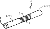
Figure 36 A is the spinal fixation that is used for of embodiments of the invention, the perspective view that has the rods of helical groove otch in it;
Figure 36 B provides rods among Figure 36 A along the cross-sectional view of the B-B line among Figure 36 A;
Figure 37 A shows the spinal fixation that is used for of embodiments of the invention, the perspective view that has the rods of interconnection in the main body of bar;
Figure 37 B is that rods among Figure 37 A is along the cross-sectional view of the B-B line among Figure 37 A;
Figure 38 A is the spinal fixation that is used for of another embodiment of the present invention, has the helical groove otch in it and has interconnection in the main body of bar, the perspective view of rods;
Figure 38 B is the top view of the rods among Figure 38 A of observing of the B-B line from Figure 38 A;
Figure 39 A is the spinal fixation that is used for of another embodiment of the present invention, the perspective view that has the rods of interconnection in the main body of bar;
Figure 39 B is that rods among Figure 39 A is along the cross-sectional view of the B-B line among the figure;
Figure 39 C has a replaceable cross-sectional view along the B-B line among the figure of the flexible piece of orthogonal interconnection substantially among Figure 39 A of an embodiment more of the present invention in the main body of bar;
Figure 40 A shows the perspective view of the rods that is used for spinal fixation of an embodiment more of the present invention;
Figure 40 B shows the cross-sectional view of the rods that is used for spinal fixation of an embodiment more of the present invention;
Figure 41 A shows the flexible vertically perspective view of part linkage unit of embodiments of the invention;
Figure 41 B shows the perspective view of the linkage unit that is equipped with fixture among Figure 41 A;
Figure 41 C shows the flexible vertically perspective view of part of having subdued length and being equipped with fixture;
Figure 42 A shows the flexible vertically side view of part linkage unit of another embodiment of the present invention;
Figure 42 B shows the flexible vertically side view of part linkage unit of an embodiment more of the present invention;
Figure 43 A shows the flexible vertically side view of part linkage unit of an embodiment more of the present invention;
Figure 43 B shows the flexible vertically perspective view of part linkage unit of another embodiment of the present invention;
Figure 43 C shows the flexible vertically side view of part linkage unit of an embodiment more of the present invention;
Figure 43 D shows the flexible vertically side view of part linkage unit of an embodiment more of the present invention;
Figure 44 shows the flexible vertically perspective view of part linkage unit of an embodiment more of the present invention;
Figure 45 A shows the flexible vertically cross-sectional view of part linkage unit of embodiments of the invention;
Figure 45 B shows the flexible vertically cross-sectional view of being made by two class materials of part of another embodiment of the present invention;
Figure 46 A-C shows the perspective view of the vertical part of metal mixed with elastomer coating of various embodiment of the present invention;
Figure 47 A-B shows the perspective view with at least one spacer and elastomeric vertical part of various embodiment of the present invention;
Figure 48 shows the flexible connection unit with spacer and elastomer coating of another embodiment of the present invention;
Figure 49 shows the flexible connection unit with spacer and elastomer coating of an embodiment more of the present invention;
Figure 50 A-D shows the variation that is used to improve the elastomeric feature that is overlying on rigid surface of various embodiment of the present invention;
Figure 51-52 shows two embodiment with flexible connection unit of at least one spacer and elastomer coating of the present invention respectively;
Figure 53 shows two flexible connection unit of the spinal column that is connected in the patient shown in Figure 52 of embodiments of the invention;
Figure 54-55 shows the additional embodiments with flexible connection unit of at least one spacer and elastomer coating of the present invention.
The specific embodiment
To describe the present invention with reference to the accompanying drawings hereinafter, wherein same from start to finish label is represented same element.
Fig. 1 has described spinal fixation system according to an embodiment of the invention.This spinal fixation system comprises two fixtures 2 (be appointed as 2 ' and 2 "), and is configured to hold and is fixed on the flexible fixed bar 4 in the adapter assembly 14, as hereinafter about the further detailed description of Fig. 3.Each fixture 2 comprises the thread spindle 10 of screw type, and it is configured to insert and be screwed in patient's the pedicle of vertebral arch.As shown in Figure 1, the axle 10 of screw type is included in the helical form external screw thread 12 that forms on the length of axle 10, and the conical end that is configured to be inserted at assigned address patient's intravertebral 10 end.Other known form of fixture 2 can be used together with the present invention who is provided with fixture 2, and fixture 2 can insert and be fixed in the spinal column and can guarantee to cooperate with bar 4.
As mentioned above, by fixture 2 is fixed on the position of expecting in the spinal column, spinal fixation system is used for the surgical intervention of spinal disease.In one embodiment, the vertebra that bar 4 passes two or more spinal columns extends, and fixing by fixture 2, so that the motion of stablizing two or more vertebras.
Fig. 2 shows the perspective view of spinal fixation system according to another embodiment of the present invention.Spinal fixation system among Fig. 2, except bar 4 comprises flexible intermediate portion 8 between two rigid end 9 that are listed in bar 4, similar with the spinal fixation system among Fig. 1.
Fig. 3 provides the exploded view of the various assemblies that adapter assembly 14 is shown of the fixture 2 among Fig. 1 and 2 according to embodiments of the invention.As shown in Figure 3, spiral thread or groove 18 that counterpart 14 comprises axle 10 the vertical socket cap 16 that is positioned at screw type, forms along the part of the inner wall surface of socket cap 16, and be configured to bar 4 is held within it U type base groove 20.Adapter assembly 14 further comprises external screw thread nut 22, and it has the spiral thread 24 in the lateral outer formation of nut 22, and wherein spiral thread 24 is configured to match with the helical form female thread 18 of socket cap 16.In another embodiment, adapter assembly 14 comprises locking cap 26, and it is configured to be installed on the part of socket cap 16, with covering and protection external screw thread nut 22, and guarantees more bar 4 is remained in the base groove 20.In one embodiment, the interior diameter of locking cap 26 is configured to guarantee that the overall diameter with socket cap 16 matches.Other the method that locking cap 26 is fixed to socket cap such as localized recess or groove (not shown) accordingly, will be obviously for those skilled in the art.In embodiment preferably, the element of fixture 2 and parts can be made by the material of the high rigidity of for example rustless steel, iron and steel, titanium or titanium alloy and durable biocompatibility.This is nonlocal or alternatively, the material of nonmetallic biocompatibility also can use, for example polymer, elastomer, resin, pottery and composite thereof.These materials are known in this area.As also known in the art and biocompatible materials as used herein, relate to the material that those can not produce side effect any chemistry or immunity after in being implanted to patient's body.
As illustrated in fig. 1 and 2, in a preferred embodiment, by flatly fixed vertical is in the base groove 20 of the counterpart 14 of the length direction of the thread spindle 10 of fixture 2 with bar 4, bar 4 is coupled to fixture 2.External screw thread nut 22 is received and is screwed into above bar 4 in the socket cap 16 then, so that bar 4 is fixed in the base groove 20.After this locking cap 26 is placed on above the socket cap 16, to cover, to protect and more firmly element to be fixed in the inner chamber of socket cap 16.According to the present invention, Fig. 4-7 shows the perspective view of the various embodiment of the bar 4 that can be used for fixture.Fig. 4 shows the bar 4 among Fig. 1, and wherein whole bar is manufactured and be designed to flexible.In one embodiment, bar 4 comprises the metal tube or the pipeline of the cylindrical wall 5 with predetermined thickness.In alternative embodiment, bar 4 can comprise by the synthetic metal mixed material of biocompatibility or be made by the synthetic material of biocompatibility fully.The example of the metal of biocompatibility has titanium, rustless steel, zirconium, tantalum, cobalt, chromium, nickel and alloy thereof.The exemplary synthetic material of biocompatibility has polymer, elastomer, resin, plastics, carbon graphite and composite thereof.These materials are widely known by the people in this area.
In one embodiment, provide flexible in order to give bar 4, cylindrical wall 5 is cut along the length of bar 4 in a spiral manner, to form helical cuts or groove 6.As obvious for the those of ordinary skill in this area, the width of helical groove 6 and adjustable density are whole so that the flexibility of aspiration level to be provided.In one embodiment, groove 6 is formed by the very thin helical cuts or the grooving of the whole thickness of the cylindrical wall that penetrates bar 4.As known for those skilled in the art, the thickness of tubular wall 5 and material also influence level of flexibility.
In one embodiment, bar 4 is designed to have substantially the flexible similar flexibility to normal back.The flexible scope at the known normal back of those skilled in the art, and one of them those of ordinary skill can easily be determined the thickness and the material of tubular wall 5, and the width of groove 6 and density, in the flexible scope at normal back, to realize the flexible or flexible scope of expectation.When this mentions groove 6, term " density " relates to the compactness of helical groove 6, or in other words, for example the distance between the adjacent grooves line 6 as shown in Figure 4.Yet, should understand the special predetermined flexible scope that the invention is not restricted to.In one embodiment, except the lateral flexibility feature with expectation, the rigidity of bar 4 should be able to be born the vertical axial load that is applied to patient's spinal column with respect to all the other normal spinal columns of patient in a similar manner along the vertical axis of spinal column.
Fig. 5 shows the bar 4 among Fig. 2, and wherein only pars intermedia 8 is made and be designed to flexible, and both ends 9 are made inflexible.In one embodiment, do not have the metal particle end ring of groove or medicated cap 9 ' can be enclosed within on each end of the bar 4 among Fig. 4 in it, make end 9 have rigidity.Ring or medicated cap 9 ' can use such as extruding and/or with metal solder known method together and permanently be fixed to the end of bar 4.In another embodiment, helical groove 6 only is cut along the length of pars intermedia 8, and end 9 comprises the tubular wall 5 that does not have groove 6.The tubular wall of being made by rigid metal or metal mixed material that does not have groove 65 shows higher rigidity.
Fig. 6 shows the other embodiment of the bar 4 with a plurality of parts, and two flexible parts 8 are inserted between three rigid portion 9.For example this embodiment can be used for relative to each other stablizing three adjacent vertebraes, wherein three LOCATION OF PEDICLE SCREW FIXATION are to a corresponding vertebra, and three rigid portion 9 are connected on the adapter assembly 14 of corresponding pedicle screw 2, as mentioned in about the description of Fig. 3.During each of flexible part 8 and rigid portion 9 can be made into as mentioned about the description of Fig. 5.
Fig. 7 shows another embodiment of bar 4, and it has prebuckling structure and structure, to meet and to keep the bending of patient's the spinal column that is called as lordosis, the while stabilizing spine.Usually, patient's lumbar vertebra is " C " type shape, and according to embodiments of the invention, bar 4 is when using in the spinal fixation system in Fig. 2, and its structure forms consistent with normal lumbar vertebra shape.In one embodiment, pre-bending curved bar 4 comprises pars intermedia 8, and it is made into and is designed to flexible, is inserted between two rigid end 9.During pars intermedia 8 and end 9 can be made into as mentioned about the description of Fig. 5.Making the metal of all size, length and prebuckling structure or the method for hybrid metal tubular rod is widely known by the people in this area.Additionally or alternatively, as hereinafter will describing in further detail about Figure 23 A, when two adjacent pedicle screws are not to be parallel to when inserted into each other, the prebuckling structure of bar 4 and the design skew angle of can setovering.
Other design and the material that are used to produce flexible tubular bar 4 or flexible intermediate portion 8 will be described about Fig. 8-10 hereinafter.Fig. 8 shows the perspective cross-sectional view of flexible tubular bar 4 according to an embodiment of the invention or bar portion 8.In this embodiment, described about Fig. 4-7 in as mentioned, rods 4,8 is made by first metal tube 5 that is cut with helical groove 6 within it.Second pipe 30 that is cut with helical groove 31 within it and has than first pipe, 5 littler diameters is inserted in the cylindrical cavity of first pipe 5.In one embodiment, second pipe 30 has helical groove 31, and its helical groove 6 about cutting in first pipe 5 is cut along the opposite hand of spiral, makes the rotation torque feature of second pipe 30 offset at least a portion of the rotation torque feature of first pipe 5.Second flexible pipe 30 be inserted into first pipe in intracardiac, provide more ruggedness and intensity to give rods 4,8.Second pipe 30 can be by making with first pipe, 5 identical or different materials.In a preferred embodiment, be respectively applied for any or combination in the biocompatibility metal that the material of making first pipe, 5 and second pipe 30 can be a following illustrative: titanium, rustless steel, zirconium, tantalum, cobalt, chromium, nickel, aluminum, vanadium with and alloy.In the embodiment that replaces, pipe 5 and 30 can or be made by the synthetic material of biocompatibility fully by the synthetic metal mixed material of biocompatibility.The exemplary synthetic material of biocompatibility has polymer, elastomer, resin, plastics, carbon graphite and composite thereof.These materials are widely known by the people in this area.
Fig. 9 shows the perspective cross-sectional view of rods 4,8 according to another embodiment of the present invention.In one embodiment, rods 4,8 comprises the inner core of being made by the metal cable 32 of biocompatibility, and metal cable 32 comprises the thin metallic yarn such as steel yarn, titanium yarn or titanium alloy yarn of a plurality of overlappings.Cable 32 is surrounded by metal or hybrid metal, and flexible pipe 5 is cut with helical groove 6 within it as mentioned above.The quantity of the metallic yarn in the cable 32 and rigidity and the flexibility that thickness also influences bar 4,8.By changing quantity, thickness or the material of yarn, flexibility can increase or reduce.Therefore, quantity, thickness and/or the material of the metallic yarn in the cable 32 can be adjusted rigidity and the flexibility that expectation is provided with the specific demand according to the patient.Those of ordinary skill in the art can easily determine quantity, thickness and the material of yarn, and is consistent with the given flexibility of pipe 5, to realize the rigid and flexible ratio characteristic of expectation for bar 4,8.In the embodiment that replaces, as mentioned above, cable 32 and a plurality of yarn can or be made by the synthetic material of biocompatibility fully by the synthetic metal mixed material of biocompatibility.
Figure 10 shows another embodiment of rods 4, and wherein flexible pipe 5 is wrapped nonmetal flexible core 34.In various embodiments, core 34 can be made by the metal of known biocompatibility, the marmem of biocompatibility (for example NITINOL) or the synthetic material of biocompatibility, such as carbon fiber, polyether-ether-ketone (PEEK), PAEK ether ketone ketone (PEKKEK) or ultra-high molecular weight polyethylene.
Figure 11 shows the perspective view of another embodiment of rods 35, and is wherein described about Fig. 9 in as mentioned, and a plurality of cables 32 interweave or are woven together to form braided cable bar 35.Braided cable bar 35 can be by making with the same material of cable mentioned above 32.Except the rigidity of aforesaid cable 32 and flexible transmutability, by changing the quantity and the thickness of the cable 32 that in braiding structure 35, uses, the rigidity of knitting rod 35 and flexible can further the modification to realize the feature of expectation.For example, in order in the bending range of known normal healthy spinal column, to realize various bent horizontal or scope, those of ordinary skill in the art can be easily the bending that provides of different size, quantity and material by the cable that is used to produce braided cable bar 35 change and measure the various designs of making braided cable bar 35.In a further embodiment, each end of braided cable bar 35 by in as mentioned about the described rigidity medicated cap of Fig. 5-7 or encircle 9 ' and encase, so that the bar 4 with flexible intermediate portion 8 and rigid end 9 to be provided.In the additional embodiments (not shown), braided cable bar 35 can be used as by the pipe 5 flexible inner cores that encase, and pipe 5 is to be cut with helical groove 6 within it with the similar mode of embodiment shown in Fig. 8-10, to produce rods 4 or bar portion 8.As term " braiding " or " braiding structure " comprise that the material of two or more cables, band, rope, silk ribbon and/or other shape interweaves with overlap mode as used herein.The various deinterleaving methods of the material of cable, band, rope, silk ribbon and/or other shape are known in the art.The present invention includes these interleaving technologies.In other exemplary embodiment (not shown), rods 35 comprises having the interlacing braiding structure of pattern that two or more bands, rope or silk ribbon overlap with the diagonal angle.
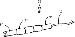
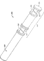
Figure 12 A shows another embodiment of flexible connection unit 36, the spacer 37 that it has two rigid end 9 ' and is inserted in the exemplary amounts between the end.In one embodiment, rigid end 9 ' and spacer can be made by metal, hybrid metal and/or the synthetic material of aforesaid biocompatibility.Linkage unit 36 also comprises flexible piece or cable 32, as mentioned in about Fig. 9 discussed, it passes axial hole or hole (not shown) in each rigid end 9 ' and the spacer 37.Figure 12 B shows the exploded view of linkage unit 36, and it further shows cable 32 and how to pass vertical axis hole of rigid end 9 ' and spacer 37 and insert.Shown in Figure 12 B was further, each of end 9 ' and spacer 37 comprised protruding interlocking part 38, and it is configured to cooperate with the recessed interlocking hole that is close to end 9 ' or spacer 37.Figure 12 C shows decomposition side view, and with dashed lines points out to be used to hold the position and the structure in the recessed interlocking hole 39 of corresponding protruding interlocking part 38.
Figure 13 shows the perspective view of flexible connection unit 40 according to another embodiment of the present invention.Linkage unit 40 is similar with above-mentioned linkage unit 36, yet spacer 42 is configured to have shape and the design same with rigid end 9 '.In addition, end 9 ' have be positioned at lateral side surfaces pass that its cable 32 can withdraw from withdraw from mouthful or groove 44, it uses metal clip (not shown) or other known technology and is tightened up and clamps or fixing.Flexible connecting member 36 or 40 length can change when operation thus, to be fit to each patient's special anatomical features.In one embodiment, cable 32 can use metal clip or shelves to end the device (not shown) and fix.For example, folder or shelves end device can comprise the less tubular cylinder with internal diameter bigger slightly than the diameter of cable 32, passes through to allow cable 32.Cable 32 ended the tension that device is pulled to expectation by the tubulose shelves after, shelves ended device and are compressed with clamping and hold within it cable 32.Alternatively, have in manufacturing during spacer 37,42 linkage unit 36,40 within it of predetermined number, cable 32 can use known technology to pre-fix.
Figure 14 has described spinal fixation system according to another embodiment of the present invention.This spinal fixation system comprises: at least two fixtures 2, it comprises the axle 10 with external spiral screw thread 12 of the screw type of elongation, and adapter assembly 14.This device also further comprises plate linkage unit 50, or is reduced to " plate 50 ", and it is configured to firmly be connected with the auxiliary section 14 of two fixtures 2.Plate 50 comprises two rigid connectors 51, and each has plane surface and is connected to each other by flexible intermediate portion 8.Flexible intermediate portion 8 can be made according to the above-mentioned any embodiment about Fig. 4-11.Each connector 51 comprises mating holes 52, and it is configured to hold second thread spindle 54 (Figure 15) of the adapter assembly 14 that passes it.
As shown in figure 15, the adapter assembly 14 of fixture 2 comprises bolt head 56, the top of its adjacency first thread spindle 10, and have girth or the diameter bigger than the girth of first thread spindle 10.Second thread spindle 54 extends upward from bolt head 56.Adapter assembly 14 further comprises having the nut 58 that is configured to the female thread that matches with second thread spindle 54, and one or more packing rings 60, be used for the upper surface that clamp connection 51 heads on bolt head 56, thereby securely plate 50 be connected in pedicle screw 2.
Figure 16 A and 16B show two embodiment of plate linkage unit 40, and it has during at least two counterparts 51 and the insertion and is connected at least one flexible part 8 of two adjacent connectors 51.Shown in Figure 16 A and 16B, flexible intermediate portion 8 comprises as above about the described flexible braided cable structure 36 of Figure 11.Yet flexible part 8 can be according to about above-mentioned any embodiment of Fig. 4-11 or it is in conjunction with being designed and making.Figure 16 C and 16D show the side view and the top view of the plate 50 among Figure 16 A respectively.As mentioned above, known metallurgy, organic polymer body, natural resin are used in the manufacturing of flexible connection unit 50 with dissimilar flexible intermediate portion 8 and 58 different embodiment, or composite, and suitable manufacturing and processing work can easily be finished.
Figure 16 E shows the side view of pre-bending bent plate linkage unit 50 ' according to another embodiment of the present invention.Except during the manufacturing of plate linkage unit 50 ', with outside angle θ formation or the bending, this plate linkage unit 50 ' is similar to plate 50 to connector 51 ' from parallel plane 53.As above described about the prebuckling linkage unit 4 of the similar bar among Fig. 7, this prebuckling structure is designed to imitate and support the natural torsion (for example lordosis) of spinal column.Additionally or alternatively, as hereinafter will describing in further detail about Figure 23 A, when two adjacent pedicle screws are not to be parallel to when inserted into each other, this prebuckling structure can be offset skew angle.
Figure 17 shows the perspective view of the plate linkage unit 60 with two plane connectors 62, and each has the mating holes 64 of second thread spindle 44 that is used to hold pedicle screw 2 within it.Flexible intermediate portion 8 is inserted between two connectors 62 and connects thereon.In one embodiment, flexible intermediate portion 8 is except having rectangular configuration rather than as shown in Figure 9 cylinder or circular configuration, and it is made to be similar to about the mode of the above-mentioned cable 32 of Fig. 9.Yet, be understood that flexible intermediate portion 8 can make according to design and the material of aforementioned any embodiment.
Figure 18 shows the perspective view of another embodiment of the plate 60 among Figure 17, and wherein mating holes 64 comprises that one or more cuttings go into the nut guide channel 66 on the top of connector 62, so that nut 58 (Figure 15) is placed and is fixed in the mating holes 64.Nut guide channel 66 is configured at least a portion of nut is held and kept within it, and prevents the horizontal slip of nut 58 after connector 62 has been clamped to the bolt head 56 of pedicle screw 2.
Figure 19 shows the perspective view of the bonded linkage unit 70 of plate stem, its end at linkage unit 70 has as above about the connector 4,9 or 9 ' of the described category of rigid of Fig. 4-7 like bar, and has as above connector 51 or 62 about the described similar plate of Figure 14-18 at the other end of linkage unit 70.In one embodiment, being inserted between the connector 52 (64) of the connector 9 (9 ') of similar bar and similar plate is flexible piece 8.This flexible piece 8 can be designed according to the above-described any embodiment about Fig. 8-13 and make.
Figure 20 shows the plate stem that uses among Figure 19 perspective view in conjunction with the spinal fixation system of linkage unit 70.As shown in figure 20, this fixture is used two class fixtures 2 (for example pedicle screw), as above be configured to holding plate connector 42 (64) securely, and as above about described second fixture 2 of Fig. 3 about described first fixture 2 ' of Figure 15 " be configured to keep securely joint element for bar 4,9 or 9 '.
Two spinal fixation systems that Figure 21 shows according to the embodiment shown in Fig. 1 are connected in two adjacent vertebras 80 and 82 with the perspective top view after the flexible stabilization vertebra.Figure 22 A and 22B show the flexible stabilization spare 50 that uses among Figure 16 A and the perspective top view of spinal fixation system after being connected in two or more adjacent vertebraes of spinal column of the flexible stabilization spare 58 among Figure 16 B respectively.
Figure 23 A shows the side view of spinal fixation system after the pedicle of vertebral arch that is implanted to two adjacent vertebras.As shown in this figure, pedicle screw 2 is installed in the pedicle of vertebral arch bone, makes the central shaft 80 of screw 2 from parallel plane 82 deviation angle θ, and general each other deviation angle 2 θ of the central shaft 80 of screw 2.Because limited spendable space when carrying out the intrusion operation of minimum level, this non-parallel insertion of pedicle screw 2 often takes place.In addition, because patient's spinal column natural torsion (for example lordosis), pedicle screw 2 has the trend from parallel to crooked.Thereby because how pedicle screw 2 is fixed to the non-parallel feature of pedicle of vertebral arch at last, when bar or plate linkage unit were connected in each pedicle screw 2, expectation offset that this is crooked.
Figure 23 B shows the side view of the head of pedicle screw according to an embodiment of the invention.This screw 2 comprises socket cap 84, comprise the inclined base 86 that is configured to hold and keep rods 4 along the direction that tilts except socket cap 84, outside the inclination or crooked θ of offsetting aforesaid pedicle screw 2, it is with similar about the above-mentioned socket cap 16 of Fig. 3.Improved pedicle screw 2 also comprises the stable spacer 88 of inclination, and it is configured to be fixedly mounted in the hole of socket cap 84, and keeps bar 4 downward as inclined base 86 with same inclination.Pedicle screw 2 also comprises external screw thread nut 22, it is configured to cooperate with screw along the inner surface (not shown) of socket cap 84, be used for clamping downwards and inclination spacer 88 and bar 4 being fixed to inclined base 86, thereby be fixed to the socket cap 84 of pedicle screw 2.
Figure 23 C shows the perspective view of the spacer 88 that tilts according to an embodiment of the invention.This spacer 88 comprises circular pars intermedia 90 and two the outward extending rectangle of the opposite side from circular pars intermedia 90 ends 92.Figure 23 D shows the side view of spacer 88, the inclination that passes through that it further shows compensation or offsets the angle of skew θ of pedicle screw 2.Figure 23 E shows the top view that is configured to bar 4 and inclination spacer 88 are held socket cap 84 within it.Bar 4 passes two openings or groove 94 and is contained in the cylindrical wall of socket cap 84, circle or cylindrical bore 96 that it allows bar 4 to enter socket cap 84, and be supported on the top of the inclined bases 86 that form in circle or the cylindrical bore 94.After bar 4 was positioned on the inclined base 86, rolling stabilizing spacer 88 was contained in the hole 96, made two rectangle ends 92 be contained in two grooves 94, prevented the horizontal rotation of spacer 88 in cylinder hole 96 thus.At last, external screw thread nut 22 and locking cap 26 insert on the top of inclination spacer 88, securely spacer 88 and bar 4 are remained in the socket cap 84.
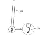
Figure 24 shows the perspective view of labelling and guiding device 100, its be used for pedicle screw 2 with the pedicle of vertebral arch of inserting on the position of labelling expectation, and the surgical technic that uses minimum level to invade guides to pedicle screw 2 position of labelling.As shown in figure 24, labelling apparatus 100 comprises tubular, hollow guiding piece 52, trocar 104 in holding in it is hollow, and trocar at one end has the muscle and the sharp end 105 of tissue up to pedicle of vertebral arch that penetrates the patient in this.Trocar 104 also comprises the trocar handle 106 that is used for easily inserting and removing trocar 104 at one end in this.In one embodiment, labelling and guiding device 100 comprise guiding piece handle 108, to allow more easily operating means 100.
As shown in figure 25, trocar 104 is long tube or cylindrical shape, and it has the diameter littler than the hollow internal diameter of guiding tube 102, so that be inserted in tubulose guiding tube 102 hollow.Trocar 104 comprises that also being used to pass pedicle of vertebral arch penetrates basivertebral tip 105 sharp or point.Trocar 104 also comprises the trocar handle 106 with diameter bigger than the hollow diameter of guiding piece pipe 102, passes completely through hollow slip with block trocar 104.Trocar handle 106 also allows more easily to operate trocar 104.
Figure 26 A and 26B provide labelling and guiding device 100 to pass muscle and the soft tissue perspective view after arriving the position of expecting on the pedicle of vertebral arch in the back that is inserted into the patient and promotion.Use the known position of determining expectation such as the technology of X ray or radiography imaging with the relatively short time.After labelling and guiding device 100 had inserted, the patient needn't be exposed to X ray with prolonging.Shown in Figure 26 B, after guiding tube 102 was positioned at the position of expecting on the pedicle of vertebral arch, trocar 104 in removing was inserted in guiding tube 102 hollow to allow the reference pin (not shown), thereby and is fixed in the pedicle of vertebral arch.
Figure 27 A and 27B show the perspective view of two embodiment of reference pin 110 and 112 respectively.As mentioned above,, after passing hollow guiding tube 102, insert and be fixed in the pedicle of vertebral arch according to reference pin 110 of the present invention and 112. Pin 110 and 112 has cylindrical shape, and its diameter is littler than the hollow internal diameter of guiding tube 102, to pass the hollow of guiding tube 102.One end of each reference pin is sharp tip 111, and it is configured to easily insert and be fixed in the pedicle of vertebral arch of spinal column.In one embodiment, shown in Figure 27 B, the other end of reference pin is in conjunction with the thread spindle 114 that is configured to cooperate with the riffled tube of the retrieval device (not shown) that is used to fetch pin 112.To be described in more detail this retrieval device about Figure 32 hereinafter.
In order to be easily inserted in the pedicle of vertebral arch bone, benchmark nail 110,112 is preferably made (for example rustless steel, iron and steel, titanium, titanium alloy) by durable and metal inflexible biocompatibility.The guiding cable of contrast prior art, because its shorter relatively length and the rigid structure of Geng Gao, benchmark nail 110,112 can easily be driven in the pedicle of vertebral arch, and does not have the danger of bending or structural failure.As mentioned above, the driving process of the guiding cable of prior art is often very difficult and time-consuming.Benchmark nail 110,112 inlet points that enter on the pedicle of vertebral arch are easier and convenient for the surgeon, in addition, and can be owing to the guiding cable that stretches out outside patient's back hinders subsequent process.
Figure 28 shows the cylindrical promotion trocar 116 of the socket cap 118 with diameter bigger than the main body that promotes trocar 116.According to the present invention, after reference pin 110 or 112 has been inserted in guiding tube 102 hollow, promotes trocar 116 and be inserted in guiding tube 102 hollow, so that reference pin 110 or 112 is driven and is fixed in the pedicle of vertebral arch.In pin insertion process, the doctor beats cover syringe needle 118 with chisel or hammer, enters in the pedicle of vertebral arch so that reference pin 110 and 112 is driven.In a preferred embodiment, promoting trocar 116 is cylindrical tubes, and it has the diameter littler than the hollow internal diameter of guiding tube 112.Promote trocar 116 and also comprise socket cap 118, it has than the bigger diameter of diameter that promotes trocar 116, more easily beats with chisel or hammer to allow the doctor.Certainly, in alternative embodiment, hammer or chisel are not necessarily.For example, depend on the environment under every kind of situation, the surgeon can select to promote or rap the head 118 that promotes trocar 116 with his or her palm or other object.
Figure 29 A shows hammer or mallet and promotes trocar 116 and how to be used for driving needle 110,112 and to pass the hollow of guiding tube 102 and enter in the assigned address of pedicle of vertebral arch.Figure 29 B shows two reference pins 110,112 and has been driven and has been fixed to the two adjacent interior cross-sectional perspective view of spinal column afterwards of vertebra.
As mentioned above, after reference pin 110 or 112 had been inserted in the pedicle of vertebral arch, in one embodiment, producing with each pin 110,112 was the bigger hole or the zone at center, easily pedicle screw 2 was inserted and was fixed in the pedicle of vertebral arch allowing.This bigger hole produces with ring awl 112 as shown in figure 30.This ring awl 122 is inserted on the reference pin 110,112 of the desired locations that is fixed on pedicle of vertebral arch.This awl 122 is cylinder hollow pipes, and the internal diameter of its hollow core is bigger than the external diameter of reference pin 110 and 112, makes pin 110,112 can be inserted in awl 122 hollow.This bores the 122 one or more sharp teeth 124 that are used to cut and pulverize tissue and bone that also comprise at one end, is the inlet point at center so that produce bigger with reference pin 110,112, makes pedicle screw 2 more easily to implant in the pedicle of vertebral arch.Figure 31 shows when ring awl 122 and is inserted on the inherent reference pin 110,112 of otch that minimum level is invaded in patient's the back, when coming for the bigger patchhole of pedicle screw 2 (not shown) generation, and the cross-sectional perspective view of patient's spinal column.As shown in figure 31, the minimum level that traction apparatus 130 has been inserted on the operative region is invaded in the otch, and the lower tube body of traction apparatus 130 expands outwardly, and promotes tissue on every side away from operative region, and performs the operation for the surgeon provides more space and visual zone.In order to insert traction apparatus 130, in one embodiment, minimum level is invaded otch and is used to insert in patient's back and produces between two inlet points of guiding tube 102 of two reference pins 110,112 and connect.Before traction apparatus 130 inserted, the expansion formerly of the otch that minimum level is invaded typically needed to use a series of segmentation dilator (not shown), and each dilator subsequently has the diameter bigger than the dilator of front.After last dilator put in place, traction apparatus 130 was under the state that contraction do not expand at its lower tube body and inserts.Traction apparatus 130 is after pedicle of vertebral arch is pushed to the degree of depth of expectation, and lower tube body is expanded, as shown in figure 31.The use of segmentation dilator and traction apparatus is widely known by the people in this area.
In one embodiment, intubate awl 122 is that pedicle screw 2 produces after the bigger patchhole, and reference pin 110,112 is removed.As mentioned above,, can use retrieval device 140, before implanting pedicle screw 2, to remove reference pin 112 if use reference pin 112.Shown in figure 32, retrieval device 140 comprises longer pipe or columnar portion, and it has and is configured to the female end 142 that matches with the external screw thread top 114 of reference pin 112.Retrieval device end 142 has been screwed to after the end of thread 114, and the doctor can pull out pedicle of vertebral arch with reference pin 112.In another embodiment, if use the reference pin 110 that does not have screw thread top, can use proper tools (for example the eye of a needle of particular design pincers) that pin 110 is taken out.
In alternative embodiment, reference pin 110,112 is not extracted from pedicle of vertebral arch.On the contrary, the pedicle screw 144 of particular design can be inserted in the pedicle of vertebral arch on pin 110,112, and need not remove pin 110,112 earlier.As shown in figure 33, the pedicle screw 144 of particular design comprises external screw thread axle 10 and adapter assembly 14 (Fig. 3), and it comprises the socket cap 16 (Fig. 3) of the linkage unit 4 (Fig. 4-13) that is used for holding flexible shaft.Alternatively, adapter assembly 14 can be configured to hold the tabular linkage unit shown in Figure 14-20.This pedicle screw 144 also is included in the vertical axial passage (not shown) in the thread spindle 10, and thread spindle 10 has opening 146 at its tip, and is configured to reference pin 110,112 is received in it.
After Figure 34 shows and use to insert in first pedicle of vertebral arch that device 150 is inserted into pedicle screw 2 on spinal column, the cross-sectional perspective view of patient's spinal column.Can be used for inserting pedicle screw 2 at various types of insertion devices 150 known in the art.As shown in figure 34, after first pedicle screw 2 had been implanted, traction apparatus 130 was adjusted and is mobile a little, was provided for inserting the space and the visual field of second pedicle screw with the position at second reference pin 110,112.
Figure 35 provides according to an embodiment of the invention after two pedicle screws 2 have implanted in the two corresponding adjacent pedicles of vertebral arch, the cross-sectional perspective view of patient's spinal column.After pedicle screw 2 has put in place, can be connected to pedicle screw about aforesaid rods, plate or the bonded linkage unit of Fig. 4-20, so that the flexible stabilization of spinal column to be provided.After this, remove traction apparatus 130 and close and/or sew up the otch that minimum level is invaded.
Figure 36 A shows the perspective view of the rods that is used for spinal fixation 200 according to another embodiment of the present invention.Bar 200 is configured to by the aforesaid fixture 2 about Fig. 1-3 fixing.In a preferred embodiment, bar 200 and the bar that below bar of describing 210,220,230 and 240 is comprised the solid cylindrical shape of making by the material of known biocompatibility, for example aforesaid rustless steel, iron and steel, titanium, titanium alloy, NITINOL and other suitable metal, synthetic metal mixed material or nonmetallic materials or composite.Shown in Figure 36 A, helicla flute 202 is cut or forms along cylindrical at least a portion length of bar 200.In exemplary embodiment, the length of bar " l " can be between 4 to 8 centimetres, and its body diameter " D " is between 4 to 8 millimeters.This helicla flute 202 has the width " w " between 0.1 to 0.5mm, and the angle of rifling θ between dried up horizontal line 50 to 85 degree.Distance between the helicla flute 202 can be between 3 to 6mm.Yet as understood by those skilled in the art, above-mentioned size only is exemplary, and can be changed to realize the flexibility that is suitable for particular patients ' or application, moment of torsion and the strength characteristic of expectation.
Figure 36 B shows the cross-sectional view of rods 200 along the line B-B among Figure 36 A.As directed, helicla flute 202 is cut towards the center of cylindrical bar 200 longitudinal axis.This groove can form continuously as the spiral form of the spiral of the spiral that is used for solid or hollow stem or interruption, or as is used for the circumferential groove of the disconnection of solid hopkinson bar.If hollow stem has the circumferential groove of the disconnection that forms within it, this groove only can partly penetrate bar material to avoid interruption.In one embodiment, shown in Figure 36 B, the degree of depth of groove 202 approximates the cylindrical radius of bar 200 greatly, and penetrates as the center longitudinal axis of cylindrical bar 200 dark.Yet the groove of the slot part of the cross-sectional area of bar and shape, groove depth, groove width, groove cross sectional form and vertical part and the spacing of groove can change, with machinery and the architectural feature of adjusting as expecting.For example, deepening or adding sipes to increase flexibility, and the spacing of increase groove and groove reduces flexibility.This can be used for being modified under the fixed bending force size of crooked bar, and the curved shape of customization bar, and the mechanical stress in bar during compensated bend are tired and improve the reliability of bar with minimum material.
Figure 37 A shows the rods that is used for spinal fixation 210 according to another embodiment of the present invention.This bar 210 comprises a plurality of transverse holes or passages 212 that bore or form in the main body of bar 210.In one embodiment, passage 212 through the center longitudinal axis of cylindrical bars 210 and with the angled φ of horizontal line.The opening that is used for each corresponding passage 212 is positioned at the opposite side of the cylindrical wall of bar 210, and adjacency channel 212 has the shared opening in a side of cylindrical wall, shown in Figure 37 A, form the internal channel 212 of the Z printed words formula of the center longitudinal axis that is horizontally through bar 210.In one embodiment, depend on the machinery and the architectural feature (for example flexibility, moment of torsion and intensity) of the expectation of bar 210, the diameter D of each passage 212 can change between 0.2 to 3mm.Yet it is exemplary should understanding these sizes, and depends on that the material of use and desired results and mechanical features can require other diameter D.Similarly, and horizontal angle φ can change with the number that changes passage 212 or the distance between the adjacency channel 212.
Figure 37 B shows the cross-sectional view of rods 210 along the line B-B among Figure 37 A.The center circle axis of a cylinder of bar 210 is passed in passage 212 cuttings, makes the opening of passage 212 form at the opposite side of the cylindrical wall of bar 210.
Figure 38 A shows the perspective view according to the rods that is used for spinal fixation 220 of an embodiment more of the present invention.Bar 220 comprises the above-mentioned helicla flute 202 about Figure 36 A and 36B, and about the above-mentioned interconnection 212 of Figure 37 A and 37B.Helicla flute 202 is in the surface of the cylindrical wall of the center of bar 220 longitudinal axis incision bar 220.As mentioned above, the size of helicla flute 202 can change according to the machinery and the architectural feature of expectation with itself and horizontal angle θ (Figure 36 A).Similarly, the size of interconnection 212 and with horizontal angle φ (Figure 37 A) can according to the expectation machinery and architectural feature change.In one embodiment, angle θ is roughly similar with φ, makes that the opening of passage 212 is consistent with the helicla flute 202 on the opposite side of the cylindrical wall of bar 220 haply.
Figure 38 B shows the top view of rods 220 along the line B-B perspective of Figure 38 A.Shown in Figure 38 B, the opening of passage 212 is consistent with helicla flute 202.By helicla flute 202 and interconnection 212 are provided in solid hopkinson bar 220, the machinery that is suitable for different patients, application and spinal fixation level and the architectural feature of many expectations can realize.
Figure 39 A shows the rods that is used for spinal fixation 230 according to an embodiment more of the present invention.This bar 230 comprises a plurality of interconnections that form 232 in the main body of bar 230.This passage 232 is haply to similar about the above-mentioned passage 212 of Figure 37 A and 37B, yet passage 232 is not to link together with Z printed words formula.On the contrary, each passage 232 is parallel to its next-door neighbour's passage 232 haply, and the opening of a passage 232 is not consistent with the opening of adjacency channel 232.Shown in Figure 39 A, be approximately 90 degree in this embodiment with horizontal angle φ.Yet, should understand that other angle φ can introduce according to the present invention.What will also be understood that is that size, size and the shape of passage 232 (and passage 212) can change, to realize the machinery and the architectural feature of expectation.For example, passage 212 and 232 shape of cross section need not to be circular.For example, they can be ellipse or rhombus on the contrary, or the shape of other expectation.
Figure 39 B shows the cross-sectional view of bar 230 along the line B-B among Figure 39 A.Shown in Figure 39 B, interconnection 232 is vertically advanced and is run transverse through the center longitudinal axis of bar 230.Figure 39 C shows the sectional view of another embodiment of bar 230, and wherein other interconnection 232 ' forms perpendicular to first interconnection 232 haply, and intersects at center circle axis of a cylinder point place with first interconnection 232.The flexibility of bar 230 can further be provided so as expected.
Figure 40 A shows the perspective view according to the rods 240 of an embodiment more of the present invention.Shown in Figure 40 A, bar 240 comprises a plurality of staggered vertical and disjoint haply each other interconnections 232 and 242.In another embodiment, the viewgraph of cross-section shown in Figure 40 B, adjacent passage 232 and 242 needn't be perpendicular to one another.Each passage 232,242 and its are close to passage 232,242 the preceding can be offset desired angle ω.As need not inappropriate experiment by those skilled in the art verifiable, size by changing passage, they quantity and they are about each other angle direction, for the rods that is used for spinal fixation system, can realize the machinery and the architectural feature of various expectations.
For example shown in Figure 22 B, sometimes for the operation of multistep spinal fixation, may expect that a joint of vertebral column is fixing rigidly, and the adjacent spinal joint dynamically (flexibly) stable.For the embodiment of vertical part of realizing this function shown in Figure 41 A.Vertically the axial part 254 of part 250 is slotted, and being provided for the flexibility of crooked increase, yet axial part 252,256 is not slotted and kept relative rigidity.Hole 258 is used for cut-out notch, breaks and improves reliability to prevent to produce.Use these diameters to be widely known by the people in this area, as reducing peak value mechanical stress in the material and reducing the method for the probability of material failure to end the groove in the material or the hole of seam with expansion.
Figure 41 B shows the assembling of the bar 250 among Figure 41 A, it uses at least three fixtures 2 (Fig. 3) to be configured to be fixed in patient's the spinal column, and have be arranged on first pair between the fixture 2 flexible part 254 and be arranged on second pair of inflexibility portion 252 between the fixture 2.
Another embodiment shown in Figure 41 C, the unslotted portion 252 of extension can provide a series of position that is used to place single fixture 2.In another embodiment, the unslotted portion of extension can be arranged on any end of fluting portion symmetrically.The development length that should recognize parts 252 provides vertical part 250 of " size is fit to all ", and it can provide the various distances between the pedicle of vertebral arch of adjacent vertebrae.Shown in Figure 41 C, the distance between the adjacent fixed part 2 and 2 ' can be adjusted by the position that is chosen in the fixture 2 on the parts 252.So any unnecessary length of parts 252 can crop or remove.
For example the groove parameter of the spacing of the groove of the shape of cross section of groove depth, groove width, groove or profile and fluting portion 254 and groove can be a constant without exception so that along fluting portion 254 the axle structure consistent with mechanical features.Sometimes structure and the mechanical features that has an axial variation for vertical part is favourable, and controlling the curved shape of partial mechanical stress levels, conventional customization, or influence is along all bending directions or along the bending resistance of selected bending direction.The cross section of the hollow vertical part of cylinder (for example) can change by changing external diameter, simultaneously the wall thickness that remains unchanged for hollow cylinder.Another embodiment revises wall thickness by adjusting internal diameter (being the diameter of cylindrical cavity), keeps the external diameter of hollow cylinder constant simultaneously.Another embodiment side by side changes internal diameter and external diameter.See that easily above-mentioned argument also is applied to have the vertical part that is not columniform shape.
Figure 42 A shows the side view of the stabilising arrangement 270 of flexible according to an embodiment of the invention screw slotting.Screw slotting portion 271 has with respect to unslotted portion 262 and the 262 ' external diameter that enlarges.Yet, owing to there is groove, if the external diameter of screw slotting portion 271 is the same with the external diameter of unslotted portion 262 and 262 ', helicla flute gives the flexibility that parts 271 increase, reduce because material cross-section is long-pending in parts 271, it also will give parts 271 with respect to the unslotted portion 262 and 262 ' the bigger unit are material stress.For screw slotting portion 271 and unslotted portion 262 and 262 ', during crooked screw slotting portion 271, the expansion of the external diameter of parts 271 can keep acceptable material stress level.
In one embodiment, if the vertical part among Figure 42 A is hollow, the internal diameter in the chamber of screw thread fluting portion 271 can be the same with the internal diameter in the chamber of unslotted portion 262 and 262 ', yet the external diameter of fluting flexible part 271 is increased the material stress when reducing bending and/or changing fluting portion 271 flexible.
Figure 42 A and 42B (hereinafter describing) show the example of vertical spinal stabilization device, and wherein flexible part is compared the corresponding end of longitudinal stability device, has different cross-sectional profiles (if the words of cylindrical bar are external diameters) or perimeter shape.
In another embodiment, the cross-sectional profiles (for example external diameter) of cross-sectional profiles (for example external diameter) and the unslotted parts of fluting flexible part keeps the same, yet the internal diameter in the chamber of the flexible part of slotting has reduced with respect to the internal diameter in the chamber of unslotted parts.This has aforesaid materials similar stress and reduces effect.
In an embodiment more of the present invention, the internal diameter of fluting flexible part and external diameter can change about the internal diameter and the external diameter of unslotted parts, and be poor with the material stress that reduces between two parts.
Figure 42 B shows the side view of another enforcement of the present invention, its body diameter or cross-sectional profiles (constant for this situation maintenance of hollow vertical part intracavity diameter simultaneously) by adjusting fluting portion 266, realize the flexible change of axle longitudinally, be in respectively between fluting portion 266 and unslotted portion 262 and 262 ' transition part 264 and 264 ' near the reducing of realization mechanical stress.The external diameter of fluting portion 266 is in the central part office minimum near fluting portion 266, and enlarges gradually towards unslotted portion 262.This provides bigger cross sectional material area with distributed force, thereby reduces the stress of unit are in the zone near the fluting portion 266 of transition part 264 and 264 '.
In another embodiment, the spacing of groove depth, groove width, groove shape of cross section and groove and groove independent or also can realize the axial change of flexibility and mechanical features with the bonded axial variation of changing as mentioned above of cylindrical cross-section.For example: (i) reduce groove depth gradually from maximum near the center of fluting portion, up at boundary with non-fluting portion near zero (Figure 43 A); (ii) reduce groove width gradually from maximum near the center of fluting portion, up at boundary with non-fluting portion near zero (Figure 43 B); (iii) allow the crooked shape of lead-over groove gradually, up to the shape that the bending that reduces is provided at the boundary with non-fluting portion from maximum near the center of fluting portion; Or (iv) near the minima at the center of the fluting portion spacing of enlarged slot and groove gradually, up to maximum (Figure 43 D) at boundary with non-fluting portion.
Figure 44 shows the vertical part that has around the elastomer coating 278 of fluting portion 276.In this embodiment, elastomer coating 278 only covers fluting portion 276, and does not cover unslotted portion 272.Also have selectable cone 274 vertically forming in the part, with at coating with slick surface transition is not provided between the coating portion.These selectable cones 274 are the fixing lengthwise position of coating also.Alternatively, coating may extend in the unslotted portion 272.The elastomer coating can (i) only contacts the surface of vertical part, (ii) penetrate in addition in the groove of vertical part, if or (iii) vertically part be hollow, penetrate and fill at least in part the inside of vertical part in addition.This elastomer coating provides the other control to axial and stability bending of vertical part, and the spacer between tissue and the fluting portion is provided.
This elastomer coating can be made up of any kind of of medical elastomer, for example comprises silicones, polyurethane (polyurethane), poly-carbonic acid carbamate (polycarbonateurethane) and silicones-urethane copolymers (silicone-urethane copolymer).Use various techniques known in the art, this coating can be applicable to vertical part.In a technology, resin thermoplastic or thermosetting can be ejected in the heated mold of the expectation part of vertical part, and it sticks in the mould simultaneously.The advantage of this spray up moulding is that it can be provided under room temperature and the pressure by what the replacement method was used to use and does not have enough low-viscosity clad materials.The other advantage of spray up moulding is that the external shape of coating is definite by the shape of the mould that uses.Another advantage of spray up moulding is the inside that can repeat to penetrate groove space and hollow vertical part.The foundry engieering of replacing comprises compression forming and transfer molding.
Other coating application process comprises fluid jet molding, immersion, spraying plating or uses such as the mechanical application device of painting brush and smear.These methods need clad material to use under low viscosity.The resin that for example is used for using should be suspended in uses the evaporable solvent in back.In another example, clad material is used under low viscosity, and solidifies by chemistry, heat and method of radiating subsequently.This sometimes of great use, to hide the part of not expecting to use clad material of vertical part.
Figure 45 A shows the cross section of unanimity of the flexible part of vertical part of being made by material 277.Figure 44 B shows the incomparable inconsistent cross section as the bar of the flexible part of vertical part of being made by material 277, and it comprises the part of being made by other material 279.Significantly, be applied with among Figure 45 A along the bar of the x and the power of y direction and will represent identical bending features.If parts 320 have different bending features with 330 material, being applied with along the bar of the x and the power of y direction among Figure 45 B will show different bending features.For example, if the material 279 among Figure 45 B is harder than material 277, bar will be than along the easier bending of y direction along the x direction.
Figure 46 A shows another embodiment of the vertical part of hybrid metal, and it has around the elastomer coating 278 of the cable portion 280 of vertical part.In this embodiment, elastomer coating 278 is around two braided cable between the coating end 262 280 not.This cable can be the independent cable or the multiply cable (not shown) of braiding not, and can be coaxial with end 262, or the longitudinal axis shown in Figure 46 B about end 262 leave in the heart location.Cable portion 280 straight shown in Figure 46 A, or crooked, the cable shown in Figure 46 C 281 for example.Straight cable 280 between the end 262 provides bigger tension resistance than crooked cable 281, and it stretches as the vertically elongation of part under tension.In one embodiment, end 262 and cable 280 can be made by metal or synthetic metal mixed material about the above-mentioned any desired and suitable biocompatibility of bar 4 and cable 32.In other embodiment, coating 278 can be made by any or combination in the synthetic or nonmetallic materials of above-mentioned suitable biocompatibility.
The hardness of the vertical part of hybrid metal among Figure 46 A-C can pass through to change the cable arrangement in the aforesaid elastomer coating 278, or revises by the physical geometry that changes cable 280 and/or coating 278.Those skilled in the art will recognize that the length and/or the diameter that for example pass through to change cable portion 280 and coating 278, the quantity and the position of diameter ratio or cable, and can change hardness.
Figure 47 A shows another embodiment of flexible connection unit, and it has one or more spacers 37 between two rigid end 9 ', and has the elastomer coating 278 that covers one or more spacers 37.Linkage unit also comprises cable 32, and it passes vertical axial passage or hole in each spacer 37.In one embodiment, shown in Figure 47 A, spacer 37 occupies intervals all between the end 9 ' haply, makes a plurality of spacers 37 remain between the end 9 ' position of direction of principal axis almost fixed longitudinally.In other words, spacer 37 is not in relation to cable 32 and moves substantially along the longitudinal direction or slip, because do not do so at interval between the end 9 '.Spacer 37 and/or end 9 ' that each spacer 37 is contiguous adjacent make it not have cable 32 or other the flexible piece slip of space about vertical axial passage of being positioned at the spacer 37 between the end 9 '.Coating 278 forms around each spacer 37 or around 37 groups of whole isolated things.Should recognize the compound or mixing spacer in conjunction with formation of spacer 37 and coating 278, wherein spacer 37 provides first material that mixes spacer, and coating provides second material that mixes spacer.In one embodiment, spacer 37 can be made by the metal or the synthetic metal mixed material of aforesaid biocompatibility, and coating 278 can be made by any or its combination in the synthetic or nonmetallic materials of above-mentioned appropriate biocompatibility.
In another embodiment, shown in Figure 47 B, spacer 37 can make and have living space between adjacent separator 37 and end 9 ' along cable 32 location.Coating 278 forms around spacer 37 and cable 32, makes that all haply intervals between adjacent separator 37 and the end 9 ' are occupied by coating 278.Thereby, coating 278 restriction bag within it spacer 37 and the motion of cable 32, and extra rigidity is provided for the flexible part between the end 9 '.Coating 278, spacer 37 and cable 32 can be made by any suitable material, for example comprise about Fig. 9,10 and the above-mentioned material of 47A.
Coating 278 among Figure 47 A and the B is shown to encapsulate each the hybrid metal spacer 37 between all ends 9 '.Those skilled in the art will recognize that the hardness of linkage unit 36 can change by a part that only covers spacer 37, interval between for example interval between the metal part of spacer 37 and the cable 32, or the interval between the spacer 37 and spacer 37 and the end 9 '.
The hardness of the flexible connection unit in above-mentioned various embodiment can change by the material of selecting various biocompatibility.For example, spacer 37 can be made by the metal of biocompatibility (for example rustless steel, titanium, titanium alloy, tantalum, zirconium, cobalt chromium, and the alloy of these materials).Spacer 37 also can be made by the material that comprises known rigidity polymer (for example UHMWPE, PEEK and polyurethane) or pottery (for example aluminium oxide or zirconium oxide).
169 Figure 48 show another embodiment of flexible connection unit 36, and it has the metal spacer 37 between rigid end 9 ', and elastomer coating 278 is around at least a portion of rigidity spacer 37.Linkage unit 36 also comprises the flexible cable 32 that passes spacer 37 and end 9 ' axial location, and wherein spacer 37, end 9 ' and cable 32 are all by elastomer coating 278 physics separately.In this embodiment, all elements of flexible connection unit can move with respect to any other element under mechanical load, and it is only limited by bending, stretching, extension and the compressive features of elastomer coating 278.Thereby the size of element and shape can be selected standing people's epispinal load, and allow linkage unit to be connected in the proper motion of its vertebra.Metal spacer 37 and coating 278 form synthetic metal mixed or compound spacer together, wherein elastomer 278 separates metal spacer 37 and corresponding rigid end 9 ' and metal cable 32, make their not rub each other, thus the generation of minimum wear fragment.Another advantage of this embodiment is that linkage unit all is flexible along all directions or degree of freedom, thereby allows bending, elongation, transverse curvature and the axially rotation of spinal column, and does not have the fixed or inflexible mechanical constraint along any direction.Elastomer coating 278 among Figure 48 is homocentric with flexible cable 32.In another embodiment (not shown), cable 32 can leave in the axial cavity that is centrally located at spacer 37, or multiply cable 32 can run through the axial cavity of spacer 37 and distributes.
Figure 49 show except each end of cable 32 with end 9 ' contacts, all the other with Figure 48 in the same flexible connection unit.In the alternative embodiment (not shown), an end of cable 32 can contact with an end 9 ', and the opposite end of cable 32 separates by aforesaid covering and the other end 9 ' simultaneously.Contact between cable 32 and the end 9 ' can be sliding-contact or the fixedly contact of assembling, welding assembling or brazing assembling such as interference fit.If the two ends of cable 32 fixedly contact with end 9 ', for example be rigidly connected, the axial stiffness of flexible connection unit can increase.Only fixedly contact will be to the almost not influence of axial stiffness of linkage unit for an end of cable 32.
Figure 48 and 49 shows the hybrid metal spacer, and it comprises that hoop centers on the metal spacer 37 of elastomer coating 278.Therefore spacer 37 is at first covered on its inner surface.Keep putting in place with respect to the end in the mould 9 ' by the metal part with spacer 37, use coating 278 simultaneously, these embodiment can easily make.The additional advantage of this embodiment is that the spacer 37 that is arranged circumferentially has limited the expansion and the bending of coating 278 when linkage unit 36 mechanical loads.This restriction effect causes the firmness change of linkage unit 36, particularly axial compression, bending and shears.The hardness that those skilled in the art will recognize that linkage unit 36 can change by internal diameter, length and the quantity that changes spacer 37.
Figure 50 A-D shows and is used to improve the various features that elastomer coating 278 is fixed in the surface of any rigid member 281.Figure 50 A shows the undercut cavity in the rigid member 281, and the main body of its lumen 282 is bigger than neck, thereby elastomer coating 278 is trapped in the chamber 282.The chamber also is included in the interior littler nip 283 of wall in chamber, is used to be cross-linked elastomer coating 278.Nip 283 and undercut cavity 282 also can independently be used.Figure 50 B shows the outer barb 284 that its elastomer coating 278 is molded that centers on the rigid member 281.Figure 50 C shows the hole 285 that its elastomer coating 278 is molded of passing of the wall that passes rigid member 281.In one embodiment, elastomer coating 278 covers around the surfaces externally and internally of the wall in hole 285.Figure 50 D shows rigid member 281 at the rough surface 281 ' that has with elastomer coating 278 interfaces.Rough surface can be formed by the whole bag of tricks, for example comprises blasting treatment, bead, plasma jet, chemical etching and various process technology.The use that can be bonded to each other of any feature shown in Figure 50 A-D, or combine with cleaning, passivation or chemical painted surface treatment such as the surface of rigid member 281.
Figure 51 shows another embodiment of spacer 37 and end 9 ', and wherein spacer 37 and end 9 ' are separated by elastomer coating 278 physics, and is configured to make that it can reinforce elastomer coating 278 when linkage unit 36 mechanical loads.Spacer 37 and end 9 ' comprise overlapping portion, its physical restriction end 9 ' shear displacemant relative to each other, and do not need confinement end 9 ' axial displacement relative to each other.Figure 51 is the combination of the shape of exemplary any amount of spacer 37 and end 9 ', and it can be used for changing along one or more directions the hardness of linkage units 36.Those skilled in the art will recognize that and use overlapping feature, or simply by increasing or reduce interval between rigidity spacer 37 and the end 9 ', or, can realize above-mentioned purpose by increasing additional isolation thing (not shown) and changing interval between the adjacent separator.
Figure 52 shows another embodiment of linkage unit 284, and it comprises two rigid end 285 and 286, and pars intermedia, and wherein flexible piece 287 connects ends 285 and 286 and pass axial hole in the hybrid metal spacer 288.In one embodiment, hybrid metal spacer 288 is formed by at least a metal and a kind of elastomeric material, make the metal part of spacer 289 be configured to, and the elastomer portions 290 of spacer 288 is arranged on the opposite side and the contiguous respective end portions 285 and 286 of metal part 289 by fixture acceptance and maintenance such as pedicle screw or laminar hook.
With reference to Figure 52, when end 285 and metal spacer 289 by accordingly for example fixture 2 (Fig. 2) keep, and when being attached to contiguous vertebra, linkage unit 284 provides stability, allows vertebra to move along six-freedom degree (for example x axle, y axle, z axle, inclination, lift-over and deflection) simultaneously.Although end 285 and 286 is limited hybrid metal spacer 288 motion of axial direction longitudinally substantially, the compressibility of the elastomer portions 290 of metal spacer 289 both sides and elasticity allow metal spacer 289 with respect to end 285 and 286 and/or flexible connecting member 287 along each stable motion of six-freedom degree, also provide the resistance and the stability of moving simultaneously along each of six-freedom degree.Thereby in one embodiment, linkage unit provides wider dynamic stability motion.In addition, in one embodiment, elastomer coating 290 comprises the material of high frictional force, and its opposing hybrid metal spacer 288 slides on flexible intermediate portion 287, thereby the resistance of metal spacer 289 axial direction motion longitudinally further is provided.End 285 and 286 is used any above-mentioned technology or known method and is connected with the respective end portions of hybrid metal spacer 288.End 285 is configured to have the enough length of being accepted and being kept by the fixture of pedicle screw or other type.When the metal part 289 of mixing spacer 288 cooperated and for example be fixed to fixture 2 (Fig. 3), stretched out above fixture 2 (in this side with respect to the spacer between two fixtures 2) end 286.Thereby end 286 is configured to along the axle of linkage unit 284 shorter, to minimize the length of stretching out above the linkage unit 284 of fixture 2.
In another embodiment (not shown), flexible piece 287 can depart from the center longitudinal axis setting of linkage unit 284.The bending direction that depends on linkage unit 284, this eccentric structure provides the hardness of varying level.If when being bent (for example when patient's bending backward) at linkage unit during the spinal extension 284, expectation provides higher levels of hardness, and when expecting lower level hardness when being bent (for example when patient to front curve) at linkage unit during the rachiocamposis 284, this is favourable.Additionally or alternatively, by on a side of linkage unit 284, using coating 290 quantity and the thickness different, can realize the direction hardness of the varying level of crooked outline with all the other sides of linkage unit 284.In addition, on the either side of spacer 289, can use the clad material 290 of varying number and/or type.Thereby linkage unit 284 can provide the hardness of varying level along the different motion direction of spacer 289, and therefore changes the level of stability of the different directions motion that can offer vertebra, and this vertebra is fixed to spacer 289 by fixture 2.In these embodiments, wherein the firmness level of linkage unit 284 is depended on bending direction, thereby suitable labelling (for example laser engraving, physical features etc.) can be arranged on the linkage unit 284, before the spinal column that linkage unit 284 is fixed to the patient, to indicate the appropriate direction of linkage unit 284.
Figure 53 shows the several respective vertebrae position afterwards that spinal column had been implanted and be fixed to two linkage units 284.For each linkage unit 284, hybrid metal spacer 288 is fixed to down vertebra 291, and end 285 is fixed to epipyramis 292.Shown in Figure 53, linkage unit 284 provides the nature of considering spinal column and dissects the flexibility of allowing of motion.Because intervertebral disc 293 is compared the more close pedicle of vertebral arch of vertebra 291 down with facet joint (facet joint) 294 with the pedicle of vertebral arch of epipyramis 292, therefore when the flexible part of the linkage unit 284 that is provided by hybrid metal spacer 288 is fixed to down vertebra 291, it is arranged to the horizontal plane of natural joint in off-center or the close spinal column, the i.e. horizontal plane of intervertebral disc 293 and facet joint 294.Be convenient to naturally and correct on the anatomy motion of spinal column in the flexibility at the horizontal plane place of natural joint.
Certainly, if flexible in the expectation of other zone, this can be by duplicating hybrid metal spacer 288 in the opposite end of linkage unit 294 and connector 287 is realized, shown in Figure 54.Linkage unit 295 is configured to be kept by the respective fixation part that is connected in two spacers 288.Spacer 288 in the linkage unit 295 may be longer than the spacer in the linkage unit 284 288, and making to provide the transmutability of the spacing between the vertebra.In a further embodiment, aforesaid linkage unit is extensible being stabilized in two or more joints or the motion segments between the three or more adjacent vertebraes, and can be attached to several respective vertebrae by three or more fixtures (for example pedicle screw).Thereby in one embodiment, linkage unit comprises a plurality of hybrid metal spacers 288 that are used for providing flexible stability to a plurality of joints or motion segments.In addition, hybrid metal spacer 288 can be replaced with any order or combination according to surgeon's demand with rigid end 285.Like this, can design blended multilamellar or many spinal column segment linkage unit, wherein each of linkage unit section can provide and to be suitable for corresponding every pair of level of flexibility with the expectation of stable vertebra up and down.For example, first one of linkage unit who stablizes first pair of vertebra can be very firm, and second one of linkage unit who stablizes second pair of vertebra simultaneously can be more pliable and tougher with respect to first one.According to the present invention, the parts of a large amount of expectations are in conjunction with realizing, to produce blended multilamellar or multistage linkage unit.
In various embodiments, flexible piece 287 shown in Figure 52,54 and 55 can be the solid member of rigid material, the metal of the biological example compatibility preferably as end 285 and the material same with end 285 integrally formed 286, and for good and all is fixed to end 286.Alternatively, connector 287 can be the hawser of cable, multiply cable, braiding or other structure that is used to connect end 285 and 286.The structure of connector, length and diameter will influence the flexibility of linkage unit 284, and this is clearly for those skilled in the art.Similarly, hybrid metal spacer 288 can be by the metal of biocompatibility, preferably with end 285 and 286 same materials, and biocompatibility such as silicones or polyurethane and preferably the elastomer of poly-carbonic acid carbamate make.Hybrid metal spacer 288 is shown as the external diameter same haply with rigid end 285 and 286.Alternatively, the elastomer portions of spacer 290 can have greater or lesser diameter, maybe can change diameter.The flexibility that is clear that linkage unit 284 for those skilled in the art can change by selecting clad material or change its size.
Nonmetal of hybrid metal spacer 288 or elastomer portions 290 can be connected in the surface of respective end portions 285 and 286, metal spacer 289 and/or flexible piece 287 by the whole bag of tricks that comprises those methods shown in Figure 50 A-50D.Shown in Figure 52-55, elastomer coating 290 remains on metal spacer 289 about fixed haply position, end 285 and 286, makes coating along any direction during crooked or compression when external force simultaneously, and it allows the certain relative motion of spacer 289.Thereby, in one embodiment, when metal part 289 was fixed to vertebra by fixture 2, by the compressibility restriction of the elastomer portions 290 of mixing spacer 288, along various directions compressed haply by its motion that can pass through the metal part 289 of spacer 288 for the flexibility of linkage unit 284.
Figure 55 shows the embodiment of linkage unit 296, and it has by the hybrid metal spacer of forming more than two kinds of different materials 297.Spacer 297 has elastomer portions 290 and the metal part 289 shown in Figure 52, and the bio-absorbable portion 298 of the other outside that is presented at elastomer portions 290.The bio-absorbable portion 298 of hybrid metal spacer is configured to haply to extend to from every end of the metal part of spacer 289 most proximal end of corresponding rigid end 285 and 286, with the motion of restriction metal part 297, up to bio-absorbable portion 298 deliquescing or degraded in vivo.The bio-absorbable portion 298 of spacer can be made up of at least a material of selecting from known bioabsorbable material group, it comprise polylactic acid, polyglycolic acid, polylactic-co-glycolic acid (polyglactic acid), poly-dioxy Ketohexamethylene, poly-gluconate (ester), calcium sulfate, calcium phosphate with and combination.Other known in addition those following can be used according to the invention with bioabsorbable materials of finding.
In one embodiment, linkage unit 296 can use behind spinal fusion surgery.In many cases, in the period that is right after after mixing operation operation, expectation is with implanting device spinal fixation rigidly, cures the bone graft of placing on the surgery and effectively adjacent vertebrae merged allowing.Successfully finish after the fusion, expectation is removed implanting device to allow bone graft stabilizing spine independently.This causes load in implant site, and reconstructs the bone graft that is used for reliable extended immobilization healthily.Yet, do not expect very much to implement operation for the second time to remove implanting device.Linkage unit 296 among Figure 55 provides firmer stability at first after spinal fusion, absorb through bio-absorbable portion 298 degradeds of natural process linkage unit 296 and by health then, thereby reduce the hardness of linkage unit 296, and allow bone graft to share the load of bigger percentage ratio with spinal column steady in a long-term.Flexible connection unit 296 allows the surgeon only to use the surgical procedure can be with the level of flexible stabilization from the first firmer less firm state of status transition to the second thus.Needless to say, operating elimination all is huge advantage from healthwise and economic angle for the patient.
Flexible connection unit 296 can be advantageously used in any desired situation that the level of stability of variation is provided.In addition, the correlative and the type that are incorporated into the bioabsorbable material in the linkage unit 298 can change, and with the initial hardness of change linkage unit 296, and absorb the 298 needed times of all bio-absorbable portions fully.In one embodiment, can use two or more dissimilar bioabsorbable materials, so that the transition from multistage hardness to be provided with different hardness feature and/or soak time.In another embodiment, be configured to stablize the linkage unit of a plurality of spinal column segment, can in one or more flexible parts of linkage unit, introduce bioabsorbable material, so that the change of flexible state to be provided by the various flexible parts of many spinal column segment linkage unit.In addition, bioabsorbable material 298 can be used for the flexible part of linkage unit (for example hybrid metal spacer portion) is encapsulated fully, or covers the selection portion of linkage unit simply, or fills gap, interval and/or the passage of linkage unit.In other words, the application of one or more bioabsorbable materials 298 can be carried out by the whole bag of tricks, to realize the initial and final hardness feature of expectation for one or more flexible parts of linkage unit.In addition, do not need in conjunction with bio-absorbable coating 298 and examples of non-bioabsorbable coating 290.Thereby in one embodiment, the elastomer coating 290 of the linkage unit 296 shown in Figure 55 can fully omit, or is substituted by bio-absorbable coating 298 or other bio-absorbable coating (not shown) with different hardness and/or degraded/absorption feature.
Various embodiment of the present invention are described hereinbefore.Yet the foregoing description that those skilled in the art will recognize preferred embodiment only is exemplary, and can implement the present invention according to the modification or the variation of above-mentioned disclosed device and technology.Those skilled in the art will understand the equivalent that maybe can use just conventional experiment to determine many specific embodiments of the present invention described here.These modifications, variation and equivalent are in as the spirit and scope of the present invention that propose in the appended claim.
Claims (22)
1. spinal fixation system comprises:
The first bone adapter assembly;
The second bone adapter assembly;
Have the linkage unit of longitudinal axis, it comprises:
First rigid ends comprises being contained in the described first bone adapter assembly at least in part and the surface that is connected with the described first bone adapter assembly;
Second rigid ends;
Between described first rigid ends and second rigid ends and be connected to the flexible piece of described second rigid ends; And
Spacer between described first rigid ends and second rigid ends, it comprises:
Be provided with around described flexible piece circumference first one; With
Around the setting of described flexible piece circumference and be contained in the described second bone adapter assembly at least in part and be connected to second one of the described second bone adapter assembly, wherein said first one is extended between described first rigid ends and described second one at least in part, and described first described second motion around described flexible piece of restriction.
2. spinal fixation system as claimed in claim 1, wherein said first rigid ends and described flexible piece are as a whole.
3. spinal fixation system as claimed in claim 1, the wherein said first bone adapter assembly is configured to can cooperate by the pedicle of vertebral arch of first vertebra, and the described second bone adapter assembly is configured to can cooperate by the pedicle of vertebral arch of second vertebra.
4. spinal fixation system as claimed in claim 1, wherein said first one is elastomer.
5. spinal fixation system as claimed in claim 1, wherein said first one is further extended between described second one and described second rigid ends at least in part.
6. spinal fixation system as claimed in claim 1, wherein said second one is provided with circumferentially around described flexible piece and described first one.
7. spinal fixation system as claimed in claim 1, wherein said second one is provided with circumferentially around described flexible piece and described first one, and between described first rigid ends and second rigid ends.
8. spinal fixation system as claimed in claim 1, wherein said flexible piece comprise in cable, many cables and the braided cable.
9. spinal fixation system as claimed in claim 3, contiguous described second vertebra of wherein said first vertebra.
10. spinal fixation system as claimed in claim 1, each in wherein said first bone adapter assembly and the described second bone adapter assembly all comprise the thread spindle that is used for fixing described first and second pedicles of vertebral arch of cooperation respectively.
11. spinal fixation system as claimed in claim 1, wherein, described spacer is fully between described first rigid ends and second rigid ends.
12. spinal fixation system as claimed in claim 1, wherein be fixed to down vertebra and the described second bone adapter assembly when being fixed to epipyramis when the described first bone adapter assembly, the position of described spacer is corresponding to the adjacent described epipyramis of patient's spinal column and the position in the joint between the following vertebra.
13. spinal fixation system as claimed in claim 1, wherein said flexible piece comprises independent axle.
14. spinal fixation system as claimed in claim 1, wherein said flexible piece departs from described longitudinal axis setting, so that the rigidity of first level is provided, and when described linkage unit is crooked along second direction, provide the rigidity of second level different with the rigidity of described first level when described linkage unit is crooked along first direction.
15. spinal fixation system as claimed in claim 1, wherein said spacer can move along six-freedom degree, simultaneously for all standing resistance along the moving of each in the described six-freedom degree.
16. spinal fixation system as claimed in claim 1, wherein said flexible piece are connected to described first rigid ends.
17. spinal fixation system as claimed in claim 1, wherein said flexible piece pass the axial hole that is formed in the described spacer.
18. spinal fixation system as claimed in claim 1, second one of wherein said spacer by the metal manufacturing, and first one of described spacer by the elastomeric material manufacturing.
19. spinal fixation system as claimed in claim 18 is wherein on elastomeric described first opposite side of second one that is positioned at described metal of spacer.
20. spinal fixation system as claimed in claim 18, wherein elastomeric described first one is positioned as near described first rigid ends and second rigid ends.
21. spinal fixation system as claimed in claim 18, wherein elastomeric described first one is limited the motion of described spacer around described flexible piece by elastomeric compressibility and elasticity.
22. spinal fixation system as claimed in claim 1, wherein said linkage unit comprises a plurality of spacers.
Applications Claiming Priority (8)
| Application Number | Priority Date | Filing Date | Title |
|---|---|---|---|
| KR20030066108 | 2003-09-24 | ||
| US10/728,566 US20050065516A1 (en) | 2003-09-24 | 2003-12-05 | Method and apparatus for flexible fixation of a spine |
| US10/798,014 US7763052B2 (en) | 2003-12-05 | 2004-03-10 | Method and apparatus for flexible fixation of a spine |
| US11/009,097 US20050203513A1 (en) | 2003-09-24 | 2004-12-10 | Spinal stabilization device |
| US11/072,886 | 2005-03-03 | ||
| US11/072,886 US7326210B2 (en) | 2003-09-24 | 2005-03-03 | Spinal stabilization device |
| US11/705,950 US20070225710A1 (en) | 2003-09-24 | 2007-02-13 | Spinal stabilization device |
| US11/705,955 US7988710B2 (en) | 2003-09-24 | 2007-02-13 | Spinal stabilization device |
Publications (2)
| Publication Number | Publication Date |
|---|---|
| CN101170952A CN101170952A (en) | 2008-04-30 |
| CN100586388C true CN100586388C (en) | 2010-02-03 |
Family
ID=46547449
Family Applications (3)
| Application Number | Title | Priority Date | Filing Date |
|---|---|---|---|
| CN200680015437A Expired - Fee Related CN100586388C (en) | 2003-09-24 | 2006-03-01 | Spinal stabilization device |
| CN2011101970783A Pending CN102283704A (en) | 2003-09-24 | 2008-02-12 | Spinal stabilization device |
| CN2008800049275A Expired - Fee Related CN101636118B (en) | 2003-09-24 | 2008-02-12 | Spinal stabilization device |
Family Applications After (2)
| Application Number | Title | Priority Date | Filing Date |
|---|---|---|---|
| CN2011101970783A Pending CN102283704A (en) | 2003-09-24 | 2008-02-12 | Spinal stabilization device |
| CN2008800049275A Expired - Fee Related CN101636118B (en) | 2003-09-24 | 2008-02-12 | Spinal stabilization device |
Country Status (11)
| Country | Link |
|---|---|
| US (5) | US20050203513A1 (en) |
| EP (3) | EP1827265A4 (en) |
| JP (4) | JP2008522748A (en) |
| KR (1) | KR20090119847A (en) |
| CN (3) | CN100586388C (en) |
| AU (2) | AU2006220929A1 (en) |
| CA (3) | CA2591277A1 (en) |
| CO (1) | CO6210796A2 (en) |
| IL (1) | IL185648A0 (en) |
| WO (3) | WO2006063107A2 (en) |
| ZA (1) | ZA200904538B (en) |
Families Citing this family (390)
| Publication number | Priority date | Publication date | Assignee | Title |
|---|---|---|---|---|
| JP2004516040A (en) | 2000-06-30 | 2004-06-03 | リトラン、スティーブン | Multi-shaft coupling device and method |
| FR2812185B1 (en) | 2000-07-25 | 2003-02-28 | Spine Next Sa | SEMI-RIGID CONNECTION PIECE FOR RACHIS STABILIZATION |
| US7833250B2 (en) | 2004-11-10 | 2010-11-16 | Jackson Roger P | Polyaxial bone screw with helically wound capture connection |
| DE50106374D1 (en) * | 2000-09-18 | 2005-07-07 | Zimmer Gmbh Winterthur | Pedicle screw for intervertebral support elements |
| US8353932B2 (en) | 2005-09-30 | 2013-01-15 | Jackson Roger P | Polyaxial bone anchor assembly with one-piece closure, pressure insert and plastic elongate member |
| US8292926B2 (en) | 2005-09-30 | 2012-10-23 | Jackson Roger P | Dynamic stabilization connecting member with elastic core and outer sleeve |
| US10729469B2 (en) | 2006-01-09 | 2020-08-04 | Roger P. Jackson | Flexible spinal stabilization assembly with spacer having off-axis core member |
| US20160242816A9 (en) | 2001-05-09 | 2016-08-25 | Roger P. Jackson | Dynamic spinal stabilization assembly with elastic bumpers and locking limited travel closure mechanisms |
| US7862587B2 (en) | 2004-02-27 | 2011-01-04 | Jackson Roger P | Dynamic stabilization assemblies, tool set and method |
| US10258382B2 (en) | 2007-01-18 | 2019-04-16 | Roger P. Jackson | Rod-cord dynamic connection assemblies with slidable bone anchor attachment members along the cord |
| US7207992B2 (en) | 2001-09-28 | 2007-04-24 | Stephen Ritland | Connection rod for screw or hook polyaxial system and method of use |
| CA2475200C (en) | 2002-02-20 | 2011-02-15 | Stephen Ritland | Pedicle screw connector apparatus and method |
| US6966910B2 (en) | 2002-04-05 | 2005-11-22 | Stephen Ritland | Dynamic fixation device and method of use |
| EP1585427B1 (en) | 2002-05-08 | 2012-04-11 | Stephen Ritland | Dynamic fixation device |
| US8876868B2 (en) | 2002-09-06 | 2014-11-04 | Roger P. Jackson | Helical guide and advancement flange with radially loaded lip |
| JP4598760B2 (en) * | 2003-02-25 | 2010-12-15 | リットランド、ステファン | ADJUSTING ROD AND CONNECTOR DEVICE, AND ITS USING METHOD |
| US7621918B2 (en) | 2004-11-23 | 2009-11-24 | Jackson Roger P | Spinal fixation tool set and method |
| US8540753B2 (en) | 2003-04-09 | 2013-09-24 | Roger P. Jackson | Polyaxial bone screw with uploaded threaded shank and method of assembly and use |
| US7029475B2 (en) | 2003-05-02 | 2006-04-18 | Yale University | Spinal stabilization method |
| US7377923B2 (en) | 2003-05-22 | 2008-05-27 | Alphatec Spine, Inc. | Variable angle spinal screw assembly |
| WO2004110247A2 (en) | 2003-05-22 | 2004-12-23 | Stephen Ritland | Intermuscular guide for retractor insertion and method of use |
| US7766915B2 (en) | 2004-02-27 | 2010-08-03 | Jackson Roger P | Dynamic fixation assemblies with inner core and outer coil-like member |
| US8926670B2 (en) | 2003-06-18 | 2015-01-06 | Roger P. Jackson | Polyaxial bone screw assembly |
| US8092500B2 (en) | 2007-05-01 | 2012-01-10 | Jackson Roger P | Dynamic stabilization connecting member with floating core, compression spacer and over-mold |
| US8366753B2 (en) | 2003-06-18 | 2013-02-05 | Jackson Roger P | Polyaxial bone screw assembly with fixed retaining structure |
| US7967850B2 (en) | 2003-06-18 | 2011-06-28 | Jackson Roger P | Polyaxial bone anchor with helical capture connection, insert and dual locking assembly |
| US7776067B2 (en) | 2005-05-27 | 2010-08-17 | Jackson Roger P | Polyaxial bone screw with shank articulation pressure insert and method |
| US7909869B2 (en) | 2003-08-05 | 2011-03-22 | Flexuspine, Inc. | Artificial spinal unit assemblies |
| US8052723B2 (en) | 2003-08-05 | 2011-11-08 | Flexuspine Inc. | Dynamic posterior stabilization systems and methods of use |
| US7753958B2 (en) | 2003-08-05 | 2010-07-13 | Gordon Charles R | Expandable intervertebral implant |
| US7763052B2 (en) | 2003-12-05 | 2010-07-27 | N Spine, Inc. | Method and apparatus for flexible fixation of a spine |
| US7137985B2 (en) | 2003-09-24 | 2006-11-21 | N Spine, Inc. | Marking and guidance method and system for flexible fixation of a spine |
| US7815665B2 (en) * | 2003-09-24 | 2010-10-19 | N Spine, Inc. | Adjustable spinal stabilization system |
| US8979900B2 (en) | 2003-09-24 | 2015-03-17 | DePuy Synthes Products, LLC | Spinal stabilization device |
| US20050203513A1 (en) * | 2003-09-24 | 2005-09-15 | Tae-Ahn Jahng | Spinal stabilization device |
| WO2005030068A1 (en) * | 2003-09-29 | 2005-04-07 | Synthes Gmbh | Dynamic damping element for two bones |
| US11419642B2 (en) | 2003-12-16 | 2022-08-23 | Medos International Sarl | Percutaneous access devices and bone anchor assemblies |
| US7527638B2 (en) | 2003-12-16 | 2009-05-05 | Depuy Spine, Inc. | Methods and devices for minimally invasive spinal fixation element placement |
| US7179261B2 (en) | 2003-12-16 | 2007-02-20 | Depuy Spine, Inc. | Percutaneous access devices and bone anchor assemblies |
| US8029548B2 (en) | 2008-05-05 | 2011-10-04 | Warsaw Orthopedic, Inc. | Flexible spinal stabilization element and system |
| US7789896B2 (en) * | 2005-02-22 | 2010-09-07 | Jackson Roger P | Polyaxial bone screw assembly |
| US7160300B2 (en) | 2004-02-27 | 2007-01-09 | Jackson Roger P | Orthopedic implant rod reduction tool set and method |
| US8152810B2 (en) | 2004-11-23 | 2012-04-10 | Jackson Roger P | Spinal fixation tool set and method |
| US11241261B2 (en) | 2005-09-30 | 2022-02-08 | Roger P Jackson | Apparatus and method for soft spinal stabilization using a tensionable cord and releasable end structure |
| WO2005092218A1 (en) | 2004-02-27 | 2005-10-06 | Jackson Roger P | Orthopedic implant rod reduction tool set and method |
| US7494489B2 (en) * | 2004-05-07 | 2009-02-24 | Jeffrey S. Roh | Systems and methods that facilitate minimally invasive spine surgery |
| US7553317B2 (en) * | 2004-05-07 | 2009-06-30 | Ethicon Endo-Surgery, Inc. | Instrument for effecting anastomosis of respective tissues defining two body lumens |
| US7766941B2 (en) * | 2004-05-14 | 2010-08-03 | Paul Kamaljit S | Spinal support, stabilization |
| FR2870718B1 (en) * | 2004-05-25 | 2006-09-22 | Spine Next Sa | TREATMENT ASSEMBLY FOR THE DEGENERATION OF AN INTERVERTEBRAL DISC |
| US7901435B2 (en) * | 2004-05-28 | 2011-03-08 | Depuy Spine, Inc. | Anchoring systems and methods for correcting spinal deformities |
| US20060015100A1 (en) | 2004-06-23 | 2006-01-19 | Panjabi Manohar M | Spinal stabilization devices coupled by torsional member |
| US7955357B2 (en) * | 2004-07-02 | 2011-06-07 | Ellipse Technologies, Inc. | Expandable rod system to treat scoliosis and method of using the same |
| US7651502B2 (en) | 2004-09-24 | 2010-01-26 | Jackson Roger P | Spinal fixation tool set and method for rod reduction and fastener insertion |
| DE102004048938B4 (en) | 2004-10-07 | 2015-04-02 | Synthes Gmbh | Device for the dynamic stabilization of vertebral bodies |
| US20060085076A1 (en) * | 2004-10-15 | 2006-04-20 | Manoj Krishna | Posterior spinal arthroplasty-development of a new posteriorly inserted artificial disc and an artificial facet joint |
| US8267969B2 (en) | 2004-10-20 | 2012-09-18 | Exactech, Inc. | Screw systems and methods for use in stabilization of bone structures |
| US8025680B2 (en) | 2004-10-20 | 2011-09-27 | Exactech, Inc. | Systems and methods for posterior dynamic stabilization of the spine |
| US8226690B2 (en) | 2005-07-22 | 2012-07-24 | The Board Of Trustees Of The Leland Stanford Junior University | Systems and methods for stabilization of bone structures |
| US7935134B2 (en) | 2004-10-20 | 2011-05-03 | Exactech, Inc. | Systems and methods for stabilization of bone structures |
| US8162985B2 (en) | 2004-10-20 | 2012-04-24 | The Board Of Trustees Of The Leland Stanford Junior University | Systems and methods for posterior dynamic stabilization of the spine |
| US20060265074A1 (en) | 2004-10-21 | 2006-11-23 | Manoj Krishna | Posterior spinal arthroplasty-development of a new posteriorly inserted artificial disc, a new anteriorly inserted artifical disc and an artificial facet joint |
| US8926672B2 (en) | 2004-11-10 | 2015-01-06 | Roger P. Jackson | Splay control closure for open bone anchor |
| JP2008519656A (en) | 2004-11-10 | 2008-06-12 | ロジャー・ピー・ジャクソン | Helical guide and forward flange with break extension |
| US20120029568A1 (en) * | 2006-01-09 | 2012-02-02 | Jackson Roger P | Spinal connecting members with radiused rigid sleeves and tensioned cords |
| WO2006057837A1 (en) | 2004-11-23 | 2006-06-01 | Jackson Roger P | Spinal fixation tool attachment structure |
| US8444681B2 (en) | 2009-06-15 | 2013-05-21 | Roger P. Jackson | Polyaxial bone anchor with pop-on shank, friction fit retainer and winged insert |
| US9980753B2 (en) | 2009-06-15 | 2018-05-29 | Roger P Jackson | pivotal anchor with snap-in-place insert having rotation blocking extensions |
| US9216041B2 (en) | 2009-06-15 | 2015-12-22 | Roger P. Jackson | Spinal connecting members with tensioned cords and rigid sleeves for engaging compression inserts |
| US8556938B2 (en) | 2009-06-15 | 2013-10-15 | Roger P. Jackson | Polyaxial bone anchor with non-pivotable retainer and pop-on shank, some with friction fit |
| US9393047B2 (en) | 2009-06-15 | 2016-07-19 | Roger P. Jackson | Polyaxial bone anchor with pop-on shank and friction fit retainer with low profile edge lock |
| US9168069B2 (en) | 2009-06-15 | 2015-10-27 | Roger P. Jackson | Polyaxial bone anchor with pop-on shank and winged insert with lower skirt for engaging a friction fit retainer |
| EP1814474B1 (en) | 2004-11-24 | 2011-09-14 | Samy Abdou | Devices for inter-vertebral orthopedic device placement |
| EP1719468A1 (en) * | 2004-12-17 | 2006-11-08 | Zimmer GmbH | Intervertebral stabilization system |
| US7901437B2 (en) | 2007-01-26 | 2011-03-08 | Jackson Roger P | Dynamic stabilization member with molded connection |
| US10076361B2 (en) | 2005-02-22 | 2018-09-18 | Roger P. Jackson | Polyaxial bone screw with spherical capture, compression and alignment and retention structures |
| US7578848B2 (en) * | 2005-03-03 | 2009-08-25 | Cervical Xpand, Llc | Intervertebral stabilizer |
| JP4931425B2 (en) * | 2005-03-31 | 2012-05-16 | 富士フイルム株式会社 | Drive device |
| US7993380B2 (en) * | 2005-03-31 | 2011-08-09 | Alphatel Spine, Inc. | Active compression orthopedic plate system and method for using the same |
| US20060276787A1 (en) * | 2005-05-26 | 2006-12-07 | Accin Corporation | Pedicle screw, cervical screw and rod |
| JP2007015291A (en) * | 2005-07-08 | 2007-01-25 | Olympus Imaging Corp | Cylindrical component |
| CA2615497C (en) | 2005-07-19 | 2014-03-25 | Stephen Ritland | Rod extension for extending fusion construct |
| US8523865B2 (en) | 2005-07-22 | 2013-09-03 | Exactech, Inc. | Tissue splitter |
| EP1757243B1 (en) * | 2005-08-24 | 2008-05-28 | BIEDERMANN MOTECH GmbH | Rod-shaped implant element for the application in spine surgery or trauma surgery and stabilization device with such a rod-shaped implant element |
| US7533672B2 (en) * | 2005-09-06 | 2009-05-19 | Synthes Usa, Llc | Methods and apparatus for vascular protection in spinal surgery |
| WO2007038429A1 (en) | 2005-09-27 | 2007-04-05 | Endius, Inc. | Methods and apparatuses for stabilizing the spine through an access device |
| US8105368B2 (en) | 2005-09-30 | 2012-01-31 | Jackson Roger P | Dynamic stabilization connecting member with slitted core and outer sleeve |
| US20080140076A1 (en) * | 2005-09-30 | 2008-06-12 | Jackson Roger P | Dynamic stabilization connecting member with slitted segment and surrounding external elastomer |
| US20070093814A1 (en) * | 2005-10-11 | 2007-04-26 | Callahan Ronald Ii | Dynamic spinal stabilization systems |
| US8357181B2 (en) | 2005-10-27 | 2013-01-22 | Warsaw Orthopedic, Inc. | Intervertebral prosthetic device for spinal stabilization and method of implanting same |
| US20070118119A1 (en) * | 2005-11-18 | 2007-05-24 | Zimmer Spine, Inc. | Methods and device for dynamic stabilization |
| AU2006318673A1 (en) * | 2005-11-18 | 2007-05-31 | Life Spine, Inc. | Dynamic spinal stabilization devices and systems |
| US7704271B2 (en) | 2005-12-19 | 2010-04-27 | Abdou M Samy | Devices and methods for inter-vertebral orthopedic device placement |
| ES2371701T3 (en) * | 2005-12-23 | 2012-01-09 | Biedermann Motech Gmbh | BONE ANCHORAGE ELEMENT. |
| US8641735B2 (en) * | 2006-01-27 | 2014-02-04 | Warsaw Orthopedic, Inc. | Implantable longitudinal orthopedic supports for accommodating multiple anatomical support requirements |
| US20070191841A1 (en) * | 2006-01-27 | 2007-08-16 | Sdgi Holdings, Inc. | Spinal rods having different flexural rigidities about different axes and methods of use |
| US7815663B2 (en) | 2006-01-27 | 2010-10-19 | Warsaw Orthopedic, Inc. | Vertebral rods and methods of use |
| US7578849B2 (en) * | 2006-01-27 | 2009-08-25 | Warsaw Orthopedic, Inc. | Intervertebral implants and methods of use |
| US7682376B2 (en) | 2006-01-27 | 2010-03-23 | Warsaw Orthopedic, Inc. | Interspinous devices and methods of use |
| EP1815812B1 (en) * | 2006-02-03 | 2009-07-29 | Spinelab AG | Spinal implant |
| US20070233064A1 (en) * | 2006-02-17 | 2007-10-04 | Holt Development L.L.C. | Apparatus and method for flexible spinal fixation |
| US20080269804A1 (en) * | 2006-02-17 | 2008-10-30 | Holt Development L.L.C. | Apparatus and method for flexible spinal fixation |
| US20070233091A1 (en) * | 2006-02-23 | 2007-10-04 | Naifeh Bill R | Multi-level spherical linkage implant system |
| US20070233073A1 (en) * | 2006-03-02 | 2007-10-04 | Sdgi Holdings, Inc. | Spinal rod characterized by a time-varying stiffness |
| US8118869B2 (en) | 2006-03-08 | 2012-02-21 | Flexuspine, Inc. | Dynamic interbody device |
| US8025681B2 (en) | 2006-03-29 | 2011-09-27 | Theken Spine, Llc | Dynamic motion spinal stabilization system |
| WO2007114834A1 (en) | 2006-04-05 | 2007-10-11 | Dong Myung Jeon | Multi-axial, double locking bone screw assembly |
| US20070239158A1 (en) * | 2006-04-10 | 2007-10-11 | Sdgi Holdings, Inc. | Elastic plates for spinal fixation or stabilization |
| GB0607535D0 (en) * | 2006-04-13 | 2006-05-24 | Fixator Innovations Ltd | Fixator member |
| US8114133B2 (en) * | 2006-04-18 | 2012-02-14 | Joseph Nicholas Logan | Spinal rod system |
| US7942905B2 (en) * | 2006-04-20 | 2011-05-17 | Warsaw Orthopedic, Inc. | Vertebral stabilizer |
| US20070270821A1 (en) * | 2006-04-28 | 2007-11-22 | Sdgi Holdings, Inc. | Vertebral stabilizer |
| US8361129B2 (en) * | 2006-04-28 | 2013-01-29 | Depuy Spine, Inc. | Large diameter bone anchor assembly |
| US20070270838A1 (en) * | 2006-05-08 | 2007-11-22 | Sdgi Holdings, Inc. | Dynamic spinal stabilization device with dampener |
| DE602006016407D1 (en) * | 2006-05-16 | 2010-10-07 | Biedermann Motech Gmbh | Longitudinal part for spine or trauma surgery |
| US8858600B2 (en) * | 2006-06-08 | 2014-10-14 | Spinadyne, Inc. | Dynamic spinal stabilization device |
| US7905906B2 (en) * | 2006-06-08 | 2011-03-15 | Disc Motion Technologies, Inc. | System and method for lumbar arthroplasty |
| US20070288009A1 (en) * | 2006-06-08 | 2007-12-13 | Steven Brown | Dynamic spinal stabilization device |
| US20080058808A1 (en) * | 2006-06-14 | 2008-03-06 | Spartek Medical, Inc. | Implant system and method to treat degenerative disorders of the spine |
| US20070299442A1 (en) * | 2006-06-26 | 2007-12-27 | Sdgi Holdings, Inc. | Vertebral stabilizer |
| US8449576B2 (en) | 2006-06-28 | 2013-05-28 | DePuy Synthes Products, LLC | Dynamic fixation system |
| US7959564B2 (en) | 2006-07-08 | 2011-06-14 | Stephen Ritland | Pedicle seeker and retractor, and methods of use |
| US20080033433A1 (en) * | 2006-08-01 | 2008-02-07 | Dante Implicito | Dynamic spinal stabilization device |
| US7806913B2 (en) * | 2006-08-16 | 2010-10-05 | Depuy Spine, Inc. | Modular multi-level spine stabilization system and method |
| US8894661B2 (en) | 2007-08-16 | 2014-11-25 | Smith & Nephew, Inc. | Helicoil interference fixation system for attaching a graft ligament to a bone |
| ES2453196T3 (en) * | 2006-08-24 | 2014-04-04 | Biedermann Technologies Gmbh & Co. Kg | Bone anchoring device |
| US7766942B2 (en) * | 2006-08-31 | 2010-08-03 | Warsaw Orthopedic, Inc. | Polymer rods for spinal applications |
| US8425601B2 (en) * | 2006-09-11 | 2013-04-23 | Warsaw Orthopedic, Inc. | Spinal stabilization devices and methods of use |
| US8267978B2 (en) * | 2006-09-14 | 2012-09-18 | Warsaw Orthopedic, Inc. | Hybrid bone fixation apparatus |
| US8308770B2 (en) * | 2006-09-22 | 2012-11-13 | Depuy Spine, Inc. | Dynamic stabilization system |
| US7947045B2 (en) * | 2006-10-06 | 2011-05-24 | Zimmer Spine, Inc. | Spinal stabilization system with flexible guides |
| US8066750B2 (en) | 2006-10-06 | 2011-11-29 | Warsaw Orthopedic, Inc | Port structures for non-rigid bone plates |
| US20080147122A1 (en) * | 2006-10-12 | 2008-06-19 | Jackson Roger P | Dynamic stabilization connecting member with molded inner segment and surrounding external elastomer |
| US8096996B2 (en) | 2007-03-20 | 2012-01-17 | Exactech, Inc. | Rod reducer |
| US20080177320A1 (en) * | 2006-10-30 | 2008-07-24 | Warsaw Orthopedic, Inc. | Vertebral Rods and Methods of Use |
| WO2008070716A2 (en) * | 2006-12-05 | 2008-06-12 | Spine Wave, Inc. | Dynamic stabilization devices and methods |
| US9867640B2 (en) * | 2006-12-07 | 2018-01-16 | Nexus Spine, LLC | Press-on pedicle screw assembly |
| CA2670988C (en) | 2006-12-08 | 2014-03-25 | Roger P. Jackson | Tool system for dynamic spinal implants |
| WO2008073830A1 (en) | 2006-12-10 | 2008-06-19 | Paradigm Spine, Llc | Posterior functionally dynamic stabilization system |
| FR2910267B1 (en) * | 2006-12-21 | 2009-01-23 | Ldr Medical Soc Par Actions Si | VERTEBRAL SUPPORT DEVICE |
| US8029544B2 (en) * | 2007-01-02 | 2011-10-04 | Zimmer Spine, Inc. | Spine stiffening device |
| US20080172091A1 (en) * | 2007-01-12 | 2008-07-17 | Warsaw Orthopedic, Inc. | Spinal Stabilization System |
| US7875059B2 (en) * | 2007-01-18 | 2011-01-25 | Warsaw Orthopedic, Inc. | Variable stiffness support members |
| US7931676B2 (en) | 2007-01-18 | 2011-04-26 | Warsaw Orthopedic, Inc. | Vertebral stabilizer |
| US8475498B2 (en) | 2007-01-18 | 2013-07-02 | Roger P. Jackson | Dynamic stabilization connecting member with cord connection |
| US8366745B2 (en) | 2007-05-01 | 2013-02-05 | Jackson Roger P | Dynamic stabilization assembly having pre-compressed spacers with differential displacements |
| US11224463B2 (en) | 2007-01-18 | 2022-01-18 | Roger P. Jackson | Dynamic stabilization connecting member with pre-tensioned flexible core member |
| US9066811B2 (en) | 2007-01-19 | 2015-06-30 | Flexuspine, Inc. | Artificial functional spinal unit system and method for use |
| AU2011265331C1 (en) * | 2007-01-26 | 2014-03-27 | Roger P. Jackson | Dynamic stabilization member with molded connection |
| US8109975B2 (en) * | 2007-01-30 | 2012-02-07 | Warsaw Orthopedic, Inc. | Collar bore configuration for dynamic spinal stabilization assembly |
| US8029547B2 (en) * | 2007-01-30 | 2011-10-04 | Warsaw Orthopedic, Inc. | Dynamic spinal stabilization assembly with sliding collars |
| US8034081B2 (en) | 2007-02-06 | 2011-10-11 | CollabComl, LLC | Interspinous dynamic stabilization implant and method of implanting |
| US8308801B2 (en) * | 2007-02-12 | 2012-11-13 | Brigham Young University | Spinal implant |
| US8012177B2 (en) | 2007-02-12 | 2011-09-06 | Jackson Roger P | Dynamic stabilization assembly with frusto-conical connection |
| EP2162079B1 (en) * | 2007-02-14 | 2016-07-06 | Flex Technology Inc. | Flexible spine components |
| US10842535B2 (en) | 2007-02-14 | 2020-11-24 | William R. Krause | Flexible spine components having multiple slots |
| US8875714B2 (en) * | 2007-02-22 | 2014-11-04 | The Invention Science Fund I, Llc | Coded-sequence activation of surgical implants |
| US8740944B2 (en) * | 2007-02-28 | 2014-06-03 | Warsaw Orthopedic, Inc. | Vertebral stabilizer |
| US7959655B2 (en) * | 2007-03-06 | 2011-06-14 | Warsaw Orthopedic, Inc. | Self-aligning attachment devices and methods for attaching an elongated member to a vertebral member |
| US8292929B2 (en) * | 2007-03-16 | 2012-10-23 | Zimmer Spine, Inc. | Dynamic spinal stabilization system and method of using the same |
| WO2008115981A1 (en) * | 2007-03-19 | 2008-09-25 | Alpinespine Llc | Active compression orthopedic plate system and method for using the same |
| US8057516B2 (en) | 2007-03-21 | 2011-11-15 | Zimmer Spine, Inc. | Spinal stabilization system with rigid and flexible elements |
| US8052727B2 (en) | 2007-03-23 | 2011-11-08 | Zimmer Gmbh | System and method for insertion of flexible spinal stabilization element |
| EP1972289B1 (en) * | 2007-03-23 | 2018-10-17 | coLigne AG | Elongated stabilization member and bone anchor useful in bone and especially spinal repair processes |
| US7922725B2 (en) | 2007-04-19 | 2011-04-12 | Zimmer Spine, Inc. | Method and associated instrumentation for installation of spinal dynamic stabilization system |
| US20080269805A1 (en) | 2007-04-25 | 2008-10-30 | Warsaw Orthopedic, Inc. | Methods for correcting spinal deformities |
| US10085772B2 (en) * | 2007-04-30 | 2018-10-02 | Globus Medical, Inc. | Flexible spine stabilization system |
| US10383660B2 (en) | 2007-05-01 | 2019-08-20 | Roger P. Jackson | Soft stabilization assemblies with pretensioned cords |
| US8016832B2 (en) * | 2007-05-02 | 2011-09-13 | Zimmer Spine, Inc. | Installation systems for spinal stabilization system and related methods |
| CA2690038C (en) | 2007-05-31 | 2012-11-27 | Roger P. Jackson | Dynamic stabilization connecting member with pre-tensioned solid core |
| US8048115B2 (en) * | 2007-06-05 | 2011-11-01 | Spartek Medical, Inc. | Surgical tool and method for implantation of a dynamic bone anchor |
| US7635380B2 (en) | 2007-06-05 | 2009-12-22 | Spartek Medical, Inc. | Bone anchor with a compressor element for receiving a rod for a dynamic stabilization and motion preservation spinal implantation system and method |
| US8083772B2 (en) * | 2007-06-05 | 2011-12-27 | Spartek Medical, Inc. | Dynamic spinal rod assembly and method for dynamic stabilization of the spine |
| US8048121B2 (en) * | 2007-06-05 | 2011-11-01 | Spartek Medical, Inc. | Spine implant with a defelction rod system anchored to a bone anchor and method |
| US7985243B2 (en) | 2007-06-05 | 2011-07-26 | Spartek Medical, Inc. | Deflection rod system with mount for a dynamic stabilization and motion preservation spinal implantation system and method |
| US8092501B2 (en) * | 2007-06-05 | 2012-01-10 | Spartek Medical, Inc. | Dynamic spinal rod and method for dynamic stabilization of the spine |
| US8021396B2 (en) | 2007-06-05 | 2011-09-20 | Spartek Medical, Inc. | Configurable dynamic spinal rod and method for dynamic stabilization of the spine |
| US7993372B2 (en) | 2007-06-05 | 2011-08-09 | Spartek Medical, Inc. | Dynamic stabilization and motion preservation spinal implantation system with a shielded deflection rod system and method |
| US8114134B2 (en) | 2007-06-05 | 2012-02-14 | Spartek Medical, Inc. | Spinal prosthesis having a three bar linkage for motion preservation and dynamic stabilization of the spine |
| US20080312694A1 (en) * | 2007-06-15 | 2008-12-18 | Peterman Marc M | Dynamic stabilization rod for spinal implants and methods for manufacturing the same |
| US8292925B2 (en) * | 2007-06-19 | 2012-10-23 | Zimmer Spine, Inc. | Flexible member with variable flexibility for providing dynamic stability to a spine |
| US20090018583A1 (en) * | 2007-07-12 | 2009-01-15 | Vermillion Technologies, Llc | Dynamic spinal stabilization system incorporating a wire rope |
| JP5752935B2 (en) * | 2007-07-13 | 2015-07-22 | フレイ、ジョージ、エイ. | System and method for spinal stabilization |
| FR2930885B3 (en) * | 2007-07-24 | 2010-09-03 | Henry Graf | EXTRA-DISCAL INTERVERTEBRAL STABILIZATION ASSEMBLY FOR ARTHRODESIS |
| FR2919170B1 (en) * | 2007-07-24 | 2010-09-03 | Henry Graf | EXTRA-DISCAL ELEMENT OF INTERVERTEBRAL STABILIZATION, GAME OF SUCH ELEMENTS AND CORRESPONDING STABILIZATION ASSEMBLY |
| JP2010535593A (en) * | 2007-08-07 | 2010-11-25 | ジンテス ゲゼルシャフト ミット ベシュレンクテル ハフツング | Dynamic cable system |
| US8080038B2 (en) | 2007-08-17 | 2011-12-20 | Jmea Corporation | Dynamic stabilization device for spine |
| US8172879B2 (en) * | 2007-08-23 | 2012-05-08 | Life Spine, Inc. | Resilient spinal rod system with controllable angulation |
| US20090082815A1 (en) * | 2007-09-20 | 2009-03-26 | Zimmer Gmbh | Spinal stabilization system with transition member |
| US20090088782A1 (en) * | 2007-09-28 | 2009-04-02 | Missoum Moumene | Flexible Spinal Rod With Elastomeric Jacket |
| US20090088799A1 (en) * | 2007-10-01 | 2009-04-02 | Chung-Chun Yeh | Spinal fixation device having a flexible cable and jointed components received thereon |
| US20090088803A1 (en) * | 2007-10-01 | 2009-04-02 | Warsaw Orthopedic, Inc. | Flexible members for correcting spinal deformities |
| US20090093846A1 (en) * | 2007-10-04 | 2009-04-09 | Zimmer Spine Inc. | Pre-Curved Flexible Member For Providing Dynamic Stability To A Spine |
| US20090093819A1 (en) * | 2007-10-05 | 2009-04-09 | Abhijeet Joshi | Anisotropic spinal stabilization rod |
| US20090093843A1 (en) * | 2007-10-05 | 2009-04-09 | Lemoine Jeremy J | Dynamic spine stabilization system |
| EP2047810B1 (en) * | 2007-10-11 | 2011-09-28 | BIEDERMANN MOTECH GmbH | Modular rod system for spinal stabilization |
| EP2047811B1 (en) * | 2007-10-11 | 2011-03-30 | BIEDERMANN MOTECH GmbH | Press-fit connection for fixing a rod in a surgical device, e.g. in a spinal stabilization device |
| US20090099608A1 (en) * | 2007-10-12 | 2009-04-16 | Aesculap Implant Systems, Inc. | Rod assembly for dynamic posterior stabilization |
| US20090099606A1 (en) * | 2007-10-16 | 2009-04-16 | Zimmer Spine Inc. | Flexible member with variable flexibility for providing dynamic stability to a spine |
| US8267965B2 (en) | 2007-10-22 | 2012-09-18 | Flexuspine, Inc. | Spinal stabilization systems with dynamic interbody devices |
| US8157844B2 (en) | 2007-10-22 | 2012-04-17 | Flexuspine, Inc. | Dampener system for a posterior stabilization system with a variable length elongated member |
| US8187330B2 (en) | 2007-10-22 | 2012-05-29 | Flexuspine, Inc. | Dampener system for a posterior stabilization system with a variable length elongated member |
| US8182514B2 (en) | 2007-10-22 | 2012-05-22 | Flexuspine, Inc. | Dampener system for a posterior stabilization system with a fixed length elongated member |
| US8523912B2 (en) | 2007-10-22 | 2013-09-03 | Flexuspine, Inc. | Posterior stabilization systems with shared, dual dampener systems |
| US8162994B2 (en) | 2007-10-22 | 2012-04-24 | Flexuspine, Inc. | Posterior stabilization system with isolated, dual dampener systems |
| US20090105756A1 (en) | 2007-10-23 | 2009-04-23 | Marc Richelsoph | Spinal implant |
| US8911477B2 (en) | 2007-10-23 | 2014-12-16 | Roger P. Jackson | Dynamic stabilization member with end plate support and cable core extension |
| US8043339B2 (en) * | 2007-10-24 | 2011-10-25 | Zimmer Spine, Inc. | Flexible member for use in a spinal column and method for making |
| WO2009064419A1 (en) * | 2007-11-12 | 2009-05-22 | Dong Myung Jeon | Dynamic spinal stabilization device |
| US9232965B2 (en) | 2009-02-23 | 2016-01-12 | Nexus Spine, LLC | Press-on link for surgical screws |
| WO2009079196A1 (en) * | 2007-12-15 | 2009-06-25 | Parlato Brian D | Flexible rod assembly for spinal fixation |
| US9232968B2 (en) | 2007-12-19 | 2016-01-12 | DePuy Synthes Products, Inc. | Polymeric pedicle rods and methods of manufacturing |
| US8252028B2 (en) | 2007-12-19 | 2012-08-28 | Depuy Spine, Inc. | Posterior dynamic stabilization device |
| US20090182384A1 (en) * | 2008-01-14 | 2009-07-16 | Warsaw Orthopedic, Inc. | Material combinations for medical device implants |
| FR2926976B1 (en) * | 2008-02-04 | 2011-01-14 | Spinevision | DYNAMIC STABILIZATION ELEMENT FOR VERTEBRATES. |
| US9277940B2 (en) * | 2008-02-05 | 2016-03-08 | Zimmer Spine, Inc. | System and method for insertion of flexible spinal stabilization element |
| USD620109S1 (en) | 2008-02-05 | 2010-07-20 | Zimmer Spine, Inc. | Surgical installation tool |
| WO2009102298A1 (en) * | 2008-02-11 | 2009-08-20 | Jackson Roger P | Dynamic stabilization connecting member with slitted segment and surrounding external elastomer |
| CA2716094A1 (en) * | 2008-02-21 | 2009-08-27 | Magrod, Llc | Magnetic targeting system and method of using the same |
| US8267979B2 (en) * | 2008-02-26 | 2012-09-18 | Spartek Medical, Inc. | Load-sharing bone anchor having a deflectable post and axial spring and method for dynamic stabilization of the spine |
| US8007518B2 (en) * | 2008-02-26 | 2011-08-30 | Spartek Medical, Inc. | Load-sharing component having a deflectable post and method for dynamic stabilization of the spine |
| US8211155B2 (en) * | 2008-02-26 | 2012-07-03 | Spartek Medical, Inc. | Load-sharing bone anchor having a durable compliant member and method for dynamic stabilization of the spine |
| US8083775B2 (en) * | 2008-02-26 | 2011-12-27 | Spartek Medical, Inc. | Load-sharing bone anchor having a natural center of rotation and method for dynamic stabilization of the spine |
| US8016861B2 (en) | 2008-02-26 | 2011-09-13 | Spartek Medical, Inc. | Versatile polyaxial connector assembly and method for dynamic stabilization of the spine |
| US8337536B2 (en) | 2008-02-26 | 2012-12-25 | Spartek Medical, Inc. | Load-sharing bone anchor having a deflectable post with a compliant ring and method for stabilization of the spine |
| US8333792B2 (en) * | 2008-02-26 | 2012-12-18 | Spartek Medical, Inc. | Load-sharing bone anchor having a deflectable post and method for dynamic stabilization of the spine |
| US20100036437A1 (en) * | 2008-02-26 | 2010-02-11 | Spartek Medical, Inc. | Load-sharing bone anchor having a deflectable post with a compliant ring and method for stabilization of the spine |
| US8057515B2 (en) | 2008-02-26 | 2011-11-15 | Spartek Medical, Inc. | Load-sharing anchor having a deflectable post and centering spring and method for dynamic stabilization of the spine |
| US8097024B2 (en) | 2008-02-26 | 2012-01-17 | Spartek Medical, Inc. | Load-sharing bone anchor having a deflectable post and method for stabilization of the spine |
| US20090259257A1 (en) * | 2008-04-15 | 2009-10-15 | Warsaw Orthopedic, Inc. | Pedicule-Based Motion- Preserving Device |
| ES2387829T3 (en) * | 2008-04-28 | 2012-10-02 | Biedermann Technologies Gmbh & Co. Kg | Element for the stabilization of the spine in the form of a rod and method for its production |
| US8034083B2 (en) * | 2008-05-01 | 2011-10-11 | Custom Spine, Inc. | Artificial ligament assembly |
| US8430912B2 (en) * | 2008-05-05 | 2013-04-30 | Warsaw Orthopedic, Inc. | Dynamic stabilization rod |
| US9017384B2 (en) * | 2008-05-13 | 2015-04-28 | Stryker Spine | Composite spinal rod |
| US8784453B1 (en) | 2008-06-09 | 2014-07-22 | Melvin Law | Dynamic spinal stabilization system |
| US8043340B1 (en) | 2008-06-09 | 2011-10-25 | Melvin Law | Dynamic spinal stabilization system |
| US20090326583A1 (en) * | 2008-06-25 | 2009-12-31 | Missoum Moumene | Posterior Dynamic Stabilization System With Flexible Ligament |
| US20090326584A1 (en) * | 2008-06-27 | 2009-12-31 | Michael Andrew Slivka | Spinal Dynamic Stabilization Rods Having Interior Bumpers |
| US8211146B2 (en) * | 2008-07-03 | 2012-07-03 | Warsaw Orthopedic | Implantable device and method of forming |
| EP2306914B1 (en) * | 2008-07-03 | 2016-11-23 | William R. Krause | Flexible spine components having a concentric slot |
| JP2012529969A (en) | 2008-08-01 | 2012-11-29 | ロジャー・ピー・ジャクソン | Longitudinal connecting member with tensioning cord with sleeve |
| US8287571B2 (en) * | 2008-08-12 | 2012-10-16 | Blackstone Medical, Inc. | Apparatus for stabilizing vertebral bodies |
| ES2527594T3 (en) * | 2008-08-12 | 2015-01-27 | Biedermann Technologies Gmbh & Co. Kg | Flexible stabilization device that includes a rod and a tool to produce the rod |
| US20100042157A1 (en) * | 2008-08-15 | 2010-02-18 | Warsaw Orthopedic, Inc. | Vertebral rod system and methods of use |
| US9339320B2 (en) * | 2008-09-02 | 2016-05-17 | Bhdl Holdings, Llc | Modular pedicle screw system with tap and screw driver device |
| US8137384B2 (en) * | 2008-09-02 | 2012-03-20 | Bhdl Holdings, Llc | Modular pedicle screw system |
| EP2160988B1 (en) * | 2008-09-04 | 2012-12-26 | Biedermann Technologies GmbH & Co. KG | Rod-shaped implant in particular for stabilizing the spinal column and stabilization device including such a rod-shaped implant |
| US9603629B2 (en) | 2008-09-09 | 2017-03-28 | Intelligent Implant Systems Llc | Polyaxial screw assembly |
| US9408649B2 (en) * | 2008-09-11 | 2016-08-09 | Innovasis, Inc. | Radiolucent screw with radiopaque marker |
| AU2009298554B2 (en) | 2008-10-01 | 2016-03-31 | Sherwin Hua | System and method for wire-guided pedicle screw stabilization of spinal vertebrae |
| ES2394670T3 (en) * | 2008-10-08 | 2013-02-04 | Biedermann Technologies Gmbh & Co. Kg | Elongated implant device and vertebral stabilization device |
| ES2392362T3 (en) * | 2008-10-08 | 2012-12-10 | Biedermann Technologies Gmbh & Co. Kg | Bone anchoring device and stabilization device for bone parts or vertebrae |
| US20100094344A1 (en) * | 2008-10-14 | 2010-04-15 | Kyphon Sarl | Pedicle-Based Posterior Stabilization Members and Methods of Use |
| US20100114165A1 (en) * | 2008-11-04 | 2010-05-06 | Abbott Spine, Inc. | Posterior dynamic stabilization system with pivoting collars |
| US20100137908A1 (en) * | 2008-12-01 | 2010-06-03 | Zimmer Spine, Inc. | Dynamic Stabilization System Components Including Readily Visualized Polymeric Compositions |
| US9055979B2 (en) | 2008-12-03 | 2015-06-16 | Zimmer Gmbh | Cord for vertebral fixation having multiple stiffness phases |
| US8137355B2 (en) | 2008-12-12 | 2012-03-20 | Zimmer Spine, Inc. | Spinal stabilization installation instrumentation and methods |
| WO2010078029A1 (en) | 2008-12-17 | 2010-07-08 | Synthes Usa, Llc | Posterior spine dynamic stabilizer |
| IT1392200B1 (en) | 2008-12-17 | 2012-02-22 | N B R New Biotechnology Res | MODULAR VERTEBRAL STABILIZER. |
| WO2010070444A1 (en) | 2008-12-18 | 2010-06-24 | Medtech Research Sa | Articulated intervertebral stabilisation system |
| US20100160968A1 (en) * | 2008-12-19 | 2010-06-24 | Abbott Spine Inc. | Systems and methods for pedicle screw-based spine stabilization using flexible bands |
| WO2010075400A1 (en) * | 2008-12-22 | 2010-07-01 | Synthes Usa, Llc | Variable tension spine fixation rod |
| US20100160978A1 (en) * | 2008-12-23 | 2010-06-24 | John Carbone | Bone screw assembly with non-uniform material |
| US20100168752A1 (en) * | 2008-12-29 | 2010-07-01 | Edwards Jon M | Orthopaedic cutting tool having a chemically etched metal insert and method of manufacturing |
| US9375221B2 (en) * | 2008-12-29 | 2016-06-28 | Depuy (Ireland) | Orthopaedic cutting block having a chemically etched metal insert |
| US8137356B2 (en) | 2008-12-29 | 2012-03-20 | Zimmer Spine, Inc. | Flexible guide for insertion of a vertebral stabilization system |
| US8641734B2 (en) | 2009-02-13 | 2014-02-04 | DePuy Synthes Products, LLC | Dual spring posterior dynamic stabilization device with elongation limiting elastomers |
| US20100222823A1 (en) * | 2009-02-19 | 2010-09-02 | Bowden Anton E | Method Of Surgically Implanting A Spinal Implant |
| US9482260B1 (en) | 2009-02-24 | 2016-11-01 | William R Krause | Flexible fastening device for industrial use |
| US20100217319A1 (en) * | 2009-02-24 | 2010-08-26 | Abbott Spine Inc. | System and method for spinal stabilization |
| US8118840B2 (en) | 2009-02-27 | 2012-02-21 | Warsaw Orthopedic, Inc. | Vertebral rod and related method of manufacture |
| WO2010108010A2 (en) * | 2009-03-19 | 2010-09-23 | Halverson Peter A | Spinal implant |
| US9095436B2 (en) * | 2009-04-14 | 2015-08-04 | The Invention Science Fund I, Llc | Adjustable orthopedic implant and method for treating an orthopedic condition in a subject |
| US20100268278A1 (en) * | 2009-04-15 | 2010-10-21 | Warsaw Orthopedic, Inc. | Tension band |
| US8202301B2 (en) * | 2009-04-24 | 2012-06-19 | Warsaw Orthopedic, Inc. | Dynamic spinal rod and implantation method |
| US8292927B2 (en) * | 2009-04-24 | 2012-10-23 | Warsaw Orthopedic, Inc. | Flexible articulating spinal rod |
| US20110040331A1 (en) * | 2009-05-20 | 2011-02-17 | Jose Fernandez | Posterior stabilizer |
| EP2757988A4 (en) | 2009-06-15 | 2015-08-19 | Jackson Roger P | Polyaxial bone anchor with pop-on shank and winged insert with friction fit compressive collet |
| US11229457B2 (en) | 2009-06-15 | 2022-01-25 | Roger P. Jackson | Pivotal bone anchor assembly with insert tool deployment |
| US8998959B2 (en) | 2009-06-15 | 2015-04-07 | Roger P Jackson | Polyaxial bone anchors with pop-on shank, fully constrained friction fit retainer and lock and release insert |
| US9668771B2 (en) | 2009-06-15 | 2017-06-06 | Roger P Jackson | Soft stabilization assemblies with off-set connector |
| US8876867B2 (en) | 2009-06-24 | 2014-11-04 | Zimmer Spine, Inc. | Spinal correction tensioning system |
| US9320543B2 (en) | 2009-06-25 | 2016-04-26 | DePuy Synthes Products, Inc. | Posterior dynamic stabilization device having a mobile anchor |
| DE102009030512A1 (en) * | 2009-06-25 | 2010-12-30 | Orthobion Gmbh | Apparatus for posterior stabilization of thoracolumbar spine, has abrasion resistant material layer provided in clamping area of clamping screw and carbon-composite rod |
| US20110009906A1 (en) * | 2009-07-13 | 2011-01-13 | Zimmer Spine, Inc. | Vertebral stabilization transition connector |
| US8105360B1 (en) | 2009-07-16 | 2012-01-31 | Orthonex LLC | Device for dynamic stabilization of the spine |
| EP2279705A1 (en) * | 2009-07-28 | 2011-02-02 | Spinelab AG | Spinal implant |
| US8657856B2 (en) | 2009-08-28 | 2014-02-25 | Pioneer Surgical Technology, Inc. | Size transition spinal rod |
| US9211144B2 (en) * | 2009-09-09 | 2015-12-15 | Globus Medical, Inc. | Spine surgery device and method |
| US9433439B2 (en) * | 2009-09-10 | 2016-09-06 | Innovasis, Inc. | Radiolucent stabilizing rod with radiopaque marker |
| US20110066187A1 (en) * | 2009-09-11 | 2011-03-17 | Zimmer Spine, Inc. | Spinal stabilization system |
| US9011494B2 (en) | 2009-09-24 | 2015-04-21 | Warsaw Orthopedic, Inc. | Composite vertebral rod system and methods of use |
| US9144447B2 (en) | 2009-10-14 | 2015-09-29 | K2M, Inc. | Surgical rod scorer and method of use of the same |
| US8506603B2 (en) * | 2009-10-14 | 2013-08-13 | K2M, Inc. | Surgical rod scorer and method of use of the same |
| US8361123B2 (en) | 2009-10-16 | 2013-01-29 | Depuy Spine, Inc. | Bone anchor assemblies and methods of manufacturing and use thereof |
| US9157497B1 (en) | 2009-10-30 | 2015-10-13 | Brigham Young University | Lamina emergent torsional joint and related methods |
| US20110106162A1 (en) * | 2009-10-30 | 2011-05-05 | Warsaw Orthopedic, Inc. | Composite Connecting Elements for Spinal Stabilization Systems |
| US20110118783A1 (en) * | 2009-11-16 | 2011-05-19 | Spartek Medical, Inc. | Load-sharing bone anchor having a flexible post and method for dynamic stabilization of the spine |
| US8328849B2 (en) * | 2009-12-01 | 2012-12-11 | Zimmer Gmbh | Cord for vertebral stabilization system |
| CN102695465A (en) | 2009-12-02 | 2012-09-26 | 斯帕泰克医疗股份有限公司 | Low profile spinal prosthesis incorporating a bone anchor having a deflectable post and a compound spinal rod |
| US8764806B2 (en) | 2009-12-07 | 2014-07-01 | Samy Abdou | Devices and methods for minimally invasive spinal stabilization and instrumentation |
| US20110152937A1 (en) * | 2009-12-22 | 2011-06-23 | Warsaw Orthopedic, Inc. | Surgical Implants for Selectively Controlling Spinal Motion Segments |
| TWI381822B (en) * | 2010-01-08 | 2013-01-11 | Spinal fixation system | |
| CH702636A1 (en) * | 2010-02-04 | 2011-08-15 | Spinesave Ag | Point-symmetric plastic rod for surgical treatment of spinal column to dynamically stabilize spinal column, has two regions with different rigidities in longitudinal direction and connected with each other by adhesives, welds or combination |
| US20110218574A1 (en) * | 2010-03-03 | 2011-09-08 | Warsaw Orthopedic, Inc. | Dynamic vertebral construct |
| US8801712B2 (en) * | 2010-03-08 | 2014-08-12 | Innovasis, Inc. | Radiolucent bone plate with radiopaque marker |
| US9308080B2 (en) | 2010-03-10 | 2016-04-12 | Smith & Nephew Inc. | Composite interference screws and drivers |
| US9579188B2 (en) | 2010-03-10 | 2017-02-28 | Smith & Nephew, Inc. | Anchor having a controlled driver orientation |
| JP5899124B2 (en) | 2010-03-10 | 2016-04-06 | スミス アンド ネフュー インコーポレーテッド | Compound tightening screw and device |
| US9445844B2 (en) | 2010-03-24 | 2016-09-20 | DePuy Synthes Products, Inc. | Composite material posterior dynamic stabilization spring rod |
| CN102859997B (en) | 2010-03-26 | 2018-05-04 | 艾科星科技公司 | Multi input television receiver |
| EP3560445A1 (en) | 2010-03-30 | 2019-10-30 | Sherwin Hua | Systems for pedicle screw stabilization of spinal vertebrae |
| JP5517053B2 (en) * | 2010-03-31 | 2014-06-11 | オリンパステルモバイオマテリアル株式会社 | Fixed structure and bone plate kit |
| US8740945B2 (en) | 2010-04-07 | 2014-06-03 | Zimmer Spine, Inc. | Dynamic stabilization system using polyaxial screws |
| EP2555696B1 (en) * | 2010-04-08 | 2017-07-26 | Globus Medical, Inc. | Jointed rod |
| CN102869309A (en) * | 2010-04-30 | 2013-01-09 | 约翰·霍普金斯大学 | Intersegmental motion preservation system for use in the spine and methods for use thereof |
| US8298242B2 (en) * | 2010-04-30 | 2012-10-30 | Warsaw Orthopedic, Inc. | Systems, devices and methods for bending an elongate member |
| US8518085B2 (en) | 2010-06-10 | 2013-08-27 | Spartek Medical, Inc. | Adaptive spinal rod and methods for stabilization of the spine |
| US20120029564A1 (en) * | 2010-07-29 | 2012-02-02 | Warsaw Orthopedic, Inc. | Composite Rod for Spinal Implant Systems With Higher Modulus Core and Lower Modulus Polymeric Sleeve |
| WO2012022047A1 (en) | 2010-08-20 | 2012-02-23 | Tongji University | Rod system for gradual dynamic spinal fixation |
| KR101841519B1 (en) | 2010-08-26 | 2018-03-23 | 스파인세이브 아게 | Spinal implant set for the dynamic stabilization of the spine |
| US8382803B2 (en) | 2010-08-30 | 2013-02-26 | Zimmer Gmbh | Vertebral stabilization transition connector |
| JP2013540468A (en) * | 2010-09-08 | 2013-11-07 | ロジャー・ピー・ジャクソン | Dynamic fixing member having an elastic part and an inelastic part |
| TWI405557B (en) * | 2010-09-28 | 2013-08-21 | Spiral rod connection device | |
| TWI403305B (en) * | 2010-09-28 | 2013-08-01 | Spiral rod connection device | |
| TWI405555B (en) * | 2010-09-28 | 2013-08-21 | The attachment mechanism of the spinal fixation system | |
| TWI405556B (en) * | 2010-09-28 | 2013-08-21 | The attachment mechanism of the spinal fixation system | |
| CN103153201B (en) * | 2010-10-05 | 2016-06-29 | 斯恩蒂斯有限公司 | There is the marrow harvest device of flexible needle |
| JP2013545527A (en) | 2010-11-02 | 2013-12-26 | ロジャー・ピー・ジャクソン | Multi-axis bone anchor with pop-on shank and pivotable retainer |
| US8721566B2 (en) | 2010-11-12 | 2014-05-13 | Robert A. Connor | Spinal motion measurement device |
| DE112011104338A5 (en) | 2010-12-08 | 2013-11-07 | Aces Gmbh | Dynamic bone anchoring device |
| MX344606B (en) | 2011-03-11 | 2016-12-20 | Smith & Nephew Inc | Trephine. |
| WO2012128825A1 (en) | 2011-03-24 | 2012-09-27 | Jackson Roger P | Polyaxial bone anchor with compound articulation and pop-on shank |
| US8388687B2 (en) | 2011-03-25 | 2013-03-05 | Flexuspine, Inc. | Interbody device insertion systems and methods |
| EP2517660B1 (en) | 2011-04-25 | 2018-03-07 | Nexus Spine, L.L.C. | Coupling system to connect two or more surgical screws |
| US20120277798A1 (en) * | 2011-04-28 | 2012-11-01 | Warsaw Orthopedic, Inc. | Spinal Rod Construct to Limit Facet Impingement |
| WO2012177412A2 (en) | 2011-06-07 | 2012-12-27 | Brigham Young University | Serpentine spinal stability device and associated methods |
| US9144506B2 (en) * | 2011-08-11 | 2015-09-29 | Jeff Phelps | Interbody axis cage |
| US8845728B1 (en) | 2011-09-23 | 2014-09-30 | Samy Abdou | Spinal fixation devices and methods of use |
| EP2747670A4 (en) | 2011-10-05 | 2015-06-24 | Mark A Dodson | Modular retractor and related method |
| US9526627B2 (en) | 2011-11-17 | 2016-12-27 | Exactech, Inc. | Expandable interbody device system and method |
| WO2013106217A1 (en) | 2012-01-10 | 2013-07-18 | Jackson, Roger, P. | Multi-start closures for open implants |
| US8430916B1 (en) | 2012-02-07 | 2013-04-30 | Spartek Medical, Inc. | Spinal rod connectors, methods of use, and spinal prosthesis incorporating spinal rod connectors |
| US20130226240A1 (en) | 2012-02-22 | 2013-08-29 | Samy Abdou | Spinous process fixation devices and methods of use |
| US9427260B2 (en) * | 2012-03-01 | 2016-08-30 | Globus Medical, Inc. | Closed-head polyaxial and monaxial screws |
| EP2838438A1 (en) * | 2012-03-09 | 2015-02-25 | Keith A. Knoell | Lattice stitch surgical tension limiting device |
| US9138265B2 (en) | 2012-03-19 | 2015-09-22 | Aesculap Implant Systems, Llc | Apparatus and method for visualizing insertion of a fixation element into an implant |
| CN103356275B (en) * | 2012-03-29 | 2016-06-01 | 董健文 | A kind of Micro-movement lumber pedicle screw elastic-fixation system |
| US8894689B2 (en) | 2012-04-20 | 2014-11-25 | Omni Acquisitions, Inc. | Stabilization rod assembly for spine fixation and process of making same |
| US10695097B2 (en) | 2012-07-05 | 2020-06-30 | Spinesave Ag | Elastic rod having different degrees of stiffness for the surgical treatment of the spine |
| US9198767B2 (en) | 2012-08-28 | 2015-12-01 | Samy Abdou | Devices and methods for spinal stabilization and instrumentation |
| US9320617B2 (en) | 2012-10-22 | 2016-04-26 | Cogent Spine, LLC | Devices and methods for spinal stabilization and instrumentation |
| US8911478B2 (en) | 2012-11-21 | 2014-12-16 | Roger P. Jackson | Splay control closure for open bone anchor |
| EP2749239B1 (en) * | 2012-12-27 | 2016-12-07 | Biedermann Technologies GmbH & Co. KG | Dynamic bone anchor |
| US10058354B2 (en) | 2013-01-28 | 2018-08-28 | Roger P. Jackson | Pivotal bone anchor assembly with frictional shank head seating surfaces |
| US8852239B2 (en) | 2013-02-15 | 2014-10-07 | Roger P Jackson | Sagittal angle screw with integral shank and receiver |
| US9492288B2 (en) | 2013-02-20 | 2016-11-15 | Flexuspine, Inc. | Expandable fusion device for positioning between adjacent vertebral bodies |
| AU2014251015B2 (en) | 2013-04-09 | 2019-01-17 | Smith & Nephew, Inc. | Open-architecture interference screw |
| US9044273B2 (en) | 2013-10-07 | 2015-06-02 | Intelligent Implant Systems, Llc | Polyaxial plate rod system and surgical procedure |
| US9566092B2 (en) | 2013-10-29 | 2017-02-14 | Roger P. Jackson | Cervical bone anchor with collet retainer and outer locking sleeve |
| US9717533B2 (en) | 2013-12-12 | 2017-08-01 | Roger P. Jackson | Bone anchor closure pivot-splay control flange form guide and advancement structure |
| US9451993B2 (en) | 2014-01-09 | 2016-09-27 | Roger P. Jackson | Bi-radial pop-on cervical bone anchor |
| TWI624244B (en) * | 2014-03-28 | 2018-05-21 | Paonan Biotech Co Ltd | Spinal facet joint fusion fixture with three-dimensional mesh body |
| EP3129175A2 (en) * | 2014-04-11 | 2017-02-15 | Smith&Nephew, Inc. | Dmls orthopedic intramedullary device and method of manufacture |
| US10398565B2 (en) | 2014-04-24 | 2019-09-03 | Choice Spine, Llc | Limited profile intervertebral implant with incorporated fastening and locking mechanism |
| US9517144B2 (en) | 2014-04-24 | 2016-12-13 | Exactech, Inc. | Limited profile intervertebral implant with incorporated fastening mechanism |
| US10758274B1 (en) | 2014-05-02 | 2020-09-01 | Nuvasive, Inc. | Spinal fixation constructs and related methods |
| US9597119B2 (en) | 2014-06-04 | 2017-03-21 | Roger P. Jackson | Polyaxial bone anchor with polymer sleeve |
| US10064658B2 (en) | 2014-06-04 | 2018-09-04 | Roger P. Jackson | Polyaxial bone anchor with insert guides |
| US9642651B2 (en) | 2014-06-12 | 2017-05-09 | Brigham Young University | Inverted serpentine spinal stability device and associated methods |
| US10123831B2 (en) | 2015-03-03 | 2018-11-13 | Pioneer Surgical Technology, Inc. | Bone compression device and method |
| US10569396B2 (en) * | 2015-08-31 | 2020-02-25 | William R. Krause | Flexible shaft for transfer of rotary motion |
| US10857003B1 (en) | 2015-10-14 | 2020-12-08 | Samy Abdou | Devices and methods for vertebral stabilization |
| CN105534624A (en) * | 2016-02-02 | 2016-05-04 | 郑明辉 | Hard human body implant pressing-in instrument |
| US10744000B1 (en) | 2016-10-25 | 2020-08-18 | Samy Abdou | Devices and methods for vertebral bone realignment |
| US10973648B1 (en) | 2016-10-25 | 2021-04-13 | Samy Abdou | Devices and methods for vertebral bone realignment |
| CN106725791B (en) * | 2017-03-01 | 2023-11-28 | 常州凯耀医疗器械有限公司 | Spinal orthopedic fixation system |
| USD868254S1 (en) * | 2017-03-23 | 2019-11-26 | Paragon 28, Inc. | Tube implant |
| CN108577954B (en) * | 2018-02-13 | 2020-04-10 | 哈尔滨医科大学 | Internal absorbable lumbar vertebra limiting dynamic fixing device |
| CN110547899A (en) * | 2018-06-01 | 2019-12-10 | 何伟义 | artificial hip joint with micro dynamic function |
| JP7382976B2 (en) | 2018-06-29 | 2023-11-17 | パイオニア サージカル テクノロジー インコーポレイテッド | bone plate system |
| CN108635033B (en) * | 2018-07-20 | 2020-11-06 | 河北医科大学第三医院 | Internal fixing device for thoracolumbar anterior treatment |
| US11179248B2 (en) | 2018-10-02 | 2021-11-23 | Samy Abdou | Devices and methods for spinal implantation |
| EP3897414A4 (en) | 2018-12-21 | 2022-09-28 | Paradigm Spine, LLC. | Modular spine stabilization system and associated instruments |
| US11160580B2 (en) | 2019-04-24 | 2021-11-02 | Spine23 Inc. | Systems and methods for pedicle screw stabilization of spinal vertebrae |
| KR102263141B1 (en) * | 2019-05-30 | 2021-06-10 | 연세대학교 산학협력단 | Patient-customized device for vertebral fixation |
| CN110090071A (en) * | 2019-06-03 | 2019-08-06 | 山东航维骨科医疗器械股份有限公司 | A kind of fixed connecting sleeve of backbone |
| WO2021068009A1 (en) * | 2019-09-30 | 2021-04-08 | Hendrik Davis Johannes | Skeletal support member |
| CN110638512B (en) * | 2019-10-09 | 2021-02-12 | 温州医科大学附属第二医院、温州医科大学附属育英儿童医院 | Novel spinal deformity corrector |
| US11877779B2 (en) | 2020-03-26 | 2024-01-23 | Xtant Medical Holdings, Inc. | Bone plate system |
| CN111419365B (en) * | 2020-04-03 | 2024-03-12 | 董谢平 | Dynamic connecting rod capable of realizing gradual change switching connection |
Family Cites Families (231)
| Publication number | Priority date | Publication date | Assignee | Title |
|---|---|---|---|---|
| US36221A (en) * | 1862-08-19 | Improvement in locks | ||
| US505510A (en) * | 1893-09-26 | Patrick p | ||
| US2379577A (en) * | 1943-01-25 | 1945-07-03 | Harry H Harsted | Foldable antenna |
| US2546026A (en) * | 1947-04-15 | 1951-03-20 | Gen Electric | Flexible antenna mounting |
| US2554708A (en) * | 1948-08-25 | 1951-05-29 | Kosten Johannes | Rowing device and oar assembly |
| US3019552A (en) * | 1956-12-05 | 1962-02-06 | Schleich Friedrich | Flexible figure toy |
| US3028291A (en) * | 1959-08-26 | 1962-04-03 | Fred T Roberts | Method of making spirally corrugated reinforced flexible hose |
| US3325327A (en) * | 1964-04-27 | 1967-06-13 | Air Reduction | Method and apparatus for making a hose of helically wrapped reinforcing and web components |
| US3575194A (en) * | 1969-07-11 | 1971-04-20 | Mcmurry Oil Tools Inc | Gas-lift valve |
| US3635233A (en) * | 1970-03-19 | 1972-01-18 | Charles H Robertson | Collapsible cane and crutch construction |
| US3669133A (en) * | 1971-06-08 | 1972-06-13 | Hycor Inc | Collapsible rod |
| BE793596A (en) * | 1972-01-03 | 1973-05-02 | Dayco Corp | FLEXIBLE ELASTOMERIC HOSE, ESPECIALLY FOR VACUUM CLEANERS |
| US3858578A (en) * | 1974-01-21 | 1975-01-07 | Pravel Wilson & Matthews | Surgical retaining device |
| GB1551706A (en) * | 1975-04-28 | 1979-08-30 | Downs Surgical Ltd | Surgical implant |
| CH628803A5 (en) | 1978-05-12 | 1982-03-31 | Sulzer Ag | Implant insertable between adjacent vertebrae |
| US4378712A (en) * | 1979-02-27 | 1983-04-05 | Nippon Cable System, Inc. | Control cable |
| US4369769A (en) * | 1980-06-13 | 1983-01-25 | Edwards Charles C | Spinal fixation device and method |
| US4448191A (en) * | 1981-07-07 | 1984-05-15 | Rodnyansky Lazar I | Implantable correctant of a spinal curvature and a method for treatment of a spinal curvature |
| US4483562A (en) * | 1981-10-16 | 1984-11-20 | Arnold Schoolman | Locking flexible shaft device with live distal end attachment |
| USRE32650E (en) * | 1982-08-25 | 1988-04-26 | Body weight support system | |
| US4911346A (en) * | 1984-11-23 | 1990-03-27 | Shallman Richard W | Flexible, segmental backpack frame |
| US4743260A (en) * | 1985-06-10 | 1988-05-10 | Burton Charles V | Method for a flexible stabilization system for a vertebral column |
| US4748260A (en) | 1986-12-22 | 1988-05-31 | Ethyl Corporation | Preparation of amine alanes |
| SE466732B (en) * | 1987-10-29 | 1992-03-30 | Atos Medical Ab | LED PROTES, INCLUDING A LED BODY BETWEEN ONE COUPLE OF TAPS FOR INSTALLATION |
| US4979531A (en) * | 1988-03-25 | 1990-12-25 | Toor John W | Tent pole and method of manufacture therefor |
| DE8807485U1 (en) * | 1988-06-06 | 1989-08-10 | Mecron Medizinische Produkte Gmbh, 1000 Berlin, De | |
| DE3823737A1 (en) * | 1988-07-13 | 1990-01-18 | Lutz Biedermann | CORRECTION AND HOLDING DEVICE, ESPECIALLY FOR THE SPINE |
| USRE36221E (en) * | 1989-02-03 | 1999-06-01 | Breard; Francis Henri | Flexible inter-vertebral stabilizer as well as process and apparatus for determining or verifying its tension before installation on the spinal column |
| CH678803A5 (en) * | 1989-07-12 | 1991-11-15 | Sulzer Ag | |
| US5029847A (en) * | 1989-08-07 | 1991-07-09 | Helen Ross | Foldable exercise stick |
| US4932975A (en) * | 1989-10-16 | 1990-06-12 | Vanderbilt University | Vertebral prosthesis |
| US5055104A (en) * | 1989-11-06 | 1991-10-08 | Surgical Dynamics, Inc. | Surgically implanting threaded fusion cages between adjacent low-back vertebrae by an anterior approach |
| US5030220A (en) * | 1990-03-29 | 1991-07-09 | Advanced Spine Fixation Systems Incorporated | Spine fixation system |
| FR2666981B1 (en) * | 1990-09-21 | 1993-06-25 | Commarmond Jacques | SYNTHETIC LIGAMENT VERTEBRAL. |
| US5133716A (en) * | 1990-11-07 | 1992-07-28 | Codespi Corporation | Device for correction of spinal deformities |
| FR2672202B1 (en) * | 1991-02-05 | 1993-07-30 | Safir | BONE SURGICAL IMPLANT, ESPECIALLY FOR INTERVERTEBRAL STABILIZER. |
| DE4109941A1 (en) | 1991-03-26 | 1992-10-01 | Reljica Kostic Zlatko Dr | Flexible prosthesis for backbone - comprises flexible spring forming supporting element connected to two fixing elements attached to adjacent vertebrae |
| US5251611A (en) * | 1991-05-07 | 1993-10-12 | Zehel Wendell E | Method and apparatus for conducting exploratory procedures |
| FR2676911B1 (en) * | 1991-05-30 | 1998-03-06 | Psi Ste Civile Particuliere | INTERVERTEBRAL STABILIZATION DEVICE WITH SHOCK ABSORBERS. |
| CA2117088A1 (en) | 1991-09-05 | 1993-03-18 | David R. Holmes | Flexible tubular device for use in medical applications |
| US5246442A (en) * | 1991-12-31 | 1993-09-21 | Danek Medical, Inc. | Spinal hook |
| US5194678A (en) * | 1992-01-27 | 1993-03-16 | Terry Kramer | Firearm rest |
| DE9202745U1 (en) * | 1992-03-02 | 1992-04-30 | Howmedica Gmbh, 2314 Schoenkirchen, De | |
| FR2692952B1 (en) | 1992-06-25 | 1996-04-05 | Psi | IMPROVED SHOCK ABSORBER WITH MOVEMENT LIMIT. |
| FR2694182B1 (en) * | 1992-07-31 | 1994-10-21 | Psi | Attachment for prosthesis, especially interpedicular. |
| GB9217578D0 (en) * | 1992-08-19 | 1992-09-30 | Surgicarft Ltd | Surgical implants,etc |
| US5814046A (en) * | 1992-11-13 | 1998-09-29 | Sofamor S.N.C. | Pedicular screw and posterior spinal instrumentation |
| DE4239716C1 (en) | 1992-11-26 | 1994-08-04 | Kernforschungsz Karlsruhe | Elastic implant for stabilising degenerated spinal column segments |
| DE4243951C2 (en) * | 1992-12-23 | 1997-07-03 | Plus Endoprothetik Ag | Device for stiffening a spinal column section consisting of at least two vertebrae |
| US5507812A (en) * | 1992-12-28 | 1996-04-16 | Moore; David E. | Modular prosthetic ligament |
| US5413576A (en) * | 1993-02-10 | 1995-05-09 | Rivard; Charles-Hilaire | Apparatus for treating spinal disorder |
| FR2701650B1 (en) * | 1993-02-17 | 1995-05-24 | Psi | Double shock absorber for intervertebral stabilization. |
| FR2702362B3 (en) * | 1993-02-24 | 1995-04-14 | Soprane Sa | Fixator for osteosynthesis of the lumbosacral spine. |
| FR2702363B1 (en) | 1993-03-12 | 1995-04-21 | Biomat | Rod-shaped osteosynthesis element. |
| US5415661A (en) * | 1993-03-24 | 1995-05-16 | University Of Miami | Implantable spinal assist device |
| US5423820A (en) * | 1993-07-20 | 1995-06-13 | Danek Medical, Inc. | Surgical cable and crimp |
| US5423816A (en) * | 1993-07-29 | 1995-06-13 | Lin; Chih I. | Intervertebral locking device |
| FR2709247B1 (en) * | 1993-08-27 | 1995-09-29 | Martin Jean Raymond | Device for anchoring spinal instrumentation on a vertebra. |
| FR2709246B1 (en) * | 1993-08-27 | 1995-09-29 | Martin Jean Raymond | Dynamic implanted spinal orthosis. |
| FR2712481B1 (en) | 1993-11-18 | 1996-01-12 | Graf Henry | Improvements to flexible inter-vertebral stabilizers. |
| FR2715825A1 (en) * | 1994-02-09 | 1995-08-11 | Soprane Sa | Self-aligning rod for spinal osteosynthesis apparatus |
| EP0669109B1 (en) | 1994-02-28 | 1999-05-26 | Sulzer Orthopädie AG | Stabilizer for adjacent vertebrae |
| EP0677277A3 (en) * | 1994-03-18 | 1996-02-28 | Patrice Moreau | Spinal prosthetic assembly. |
| FR2717370A1 (en) | 1994-03-18 | 1995-09-22 | Moreau Patrice | Intervertebral stabilising prosthesis for spinal reinforcement inserted during spinal surgery |
| CA2551185C (en) * | 1994-03-28 | 2007-10-30 | Sdgi Holdings, Inc. | Apparatus and method for anterior spinal stabilization |
| FR2718946B1 (en) | 1994-04-25 | 1996-09-27 | Soprane Sa | Flexible rod for lumbosacral osteosynthesis fixator. |
| ES2081766B1 (en) * | 1994-05-13 | 1996-10-01 | Bilbao Ortiz De Zarate Jose Ra | POSTERIOR CERVICAL VERTEBRAL FIXATION SYSTEM. |
| WO1998008454A1 (en) * | 1994-05-25 | 1998-03-05 | Jackson Roger P | Apparatus and method for spinal fixation and correction of spinal deformities |
| US5488761A (en) * | 1994-07-28 | 1996-02-06 | Leone; Ronald P. | Flexible shaft and method for manufacturing same |
| FR2724553B1 (en) * | 1994-09-15 | 1996-12-20 | Tornier Sa | EXTERNAL OR INTERNAL FIXER FOR THE REPAIR OF FRACTURES OR ARTHROPLASTIES OF THE SKELETON |
| US5681311A (en) | 1994-09-15 | 1997-10-28 | Smith & Nephew, Inc. | Osteosynthesis apparatus |
| US5735752A (en) * | 1995-06-13 | 1998-04-07 | Antonious; Anthony J. | Golf club shaft and insert therefor |
| EP0840572B1 (en) * | 1995-07-18 | 2004-10-27 | Garland U. Edwards | Flexible shaft |
| US6447518B1 (en) * | 1995-07-18 | 2002-09-10 | William R. Krause | Flexible shaft components |
| JP2741584B2 (en) * | 1995-10-20 | 1998-04-22 | 株式会社ロバート・リード商会 | Bone fixation device |
| US5658286A (en) * | 1996-02-05 | 1997-08-19 | Sava; Garard A. | Fabrication of implantable bone fixation elements |
| US5688275A (en) * | 1996-02-09 | 1997-11-18 | Koros; Tibor | Spinal column rod fixation system |
| US5984970A (en) * | 1996-03-13 | 1999-11-16 | Bramlet; Dale G. | Arthroplasty joint assembly |
| US5713900A (en) * | 1996-05-31 | 1998-02-03 | Acromed Corporation | Apparatus for retaining bone portions in a desired spatial relationship |
| GB2316735B (en) * | 1996-08-30 | 2000-01-19 | Reliance Gear Co | Flexible coupling |
| FR2755844B1 (en) * | 1996-11-15 | 1999-01-29 | Stryker France Sa | OSTEOSYNTHESIS SYSTEM WITH ELASTIC DEFORMATION FOR SPINE |
| IL128261A0 (en) * | 1999-01-27 | 1999-11-30 | Disc O Tech Medical Tech Ltd | Expandable element |
| DE29711559U1 (en) * | 1997-07-02 | 1997-08-21 | Howmedica Gmbh | Elongated element for the transmission of forces |
| WO1999005980A1 (en) * | 1997-07-31 | 1999-02-11 | Plus Endoprothetik Ag | Device for stiffening and/or correcting a vertebral column or such like |
| US5964769A (en) * | 1997-08-26 | 1999-10-12 | Spinal Concepts, Inc. | Surgical cable system and method |
| US5964767A (en) * | 1997-09-12 | 1999-10-12 | Tapia; Eduardo Armando | Hollow sealable device for temporary or permanent surgical placement through a bone to provide a passageway into a cavity or internal anatomic site in a mammal |
| FR2771280B1 (en) * | 1997-11-26 | 2001-01-26 | Albert P Alby | RESILIENT VERTEBRAL CONNECTION DEVICE |
| FR2774581B1 (en) * | 1998-02-10 | 2000-08-11 | Dimso Sa | INTEREPINOUS STABILIZER TO BE ATTACHED TO SPINOUS APOPHYSIS OF TWO VERTEBRES |
| FR2775583B1 (en) * | 1998-03-04 | 2000-08-11 | Dimso Sa | SYSTEM FOR OSTEOSYNTHESIS OF THE RACHIS WITH LIGAMENT |
| US6187000B1 (en) * | 1998-08-20 | 2001-02-13 | Endius Incorporated | Cannula for receiving surgical instruments |
| US6296644B1 (en) * | 1998-08-26 | 2001-10-02 | Jean Saurat | Spinal instrumentation system with articulated modules |
| US6355038B1 (en) * | 1998-09-25 | 2002-03-12 | Perumala Corporation | Multi-axis internal spinal fixation |
| US6193720B1 (en) * | 1998-11-30 | 2001-02-27 | Depuy Orthopaedics, Inc. | Cervical spine stabilization method and system |
| JP2003523784A (en) * | 1999-04-05 | 2003-08-12 | サージカル ダイナミックス インコーポレイテッド | Artificial spinal ligament |
| US6162223A (en) | 1999-04-09 | 2000-12-19 | Smith & Nephew, Inc. | Dynamic wrist fixation apparatus for early joint motion in distal radius fractures |
| JP3025265B1 (en) * | 1999-05-17 | 2000-03-27 | 株式会社ロバート・リード商会 | Wire rod fixing device |
| US6475220B1 (en) * | 1999-10-15 | 2002-11-05 | Whiteside Biomechanics, Inc. | Spinal cable system |
| FR2799949B1 (en) | 1999-10-22 | 2002-06-28 | Abder Benazza | SPINAL OSTETHOSYNTHESIS DEVICE |
| US6811567B2 (en) * | 1999-10-22 | 2004-11-02 | Archus Orthopedics Inc. | Facet arthroplasty devices and methods |
| KR200188511Y1 (en) * | 2000-01-06 | 2000-07-15 | 구자교 | A supplement plug for spinal colulm |
| US6893462B2 (en) * | 2000-01-11 | 2005-05-17 | Regeneration Technologies, Inc. | Soft and calcified tissue implants |
| US20020133155A1 (en) * | 2000-02-25 | 2002-09-19 | Ferree Bret A. | Cross-coupled vertebral stabilizers incorporating spinal motion restriction |
| FR2805451B1 (en) * | 2000-02-29 | 2002-04-19 | Arnaud Andre Soubeiran | IMPROVED DEVICE FOR MOVING TWO BODIES IN RELATION TO ONE ANOTHER, PARTICULARLY FOR REALIZING IMPLANTABLE SYSTEMS IN THE HUMAN BODY |
| US6293949B1 (en) * | 2000-03-01 | 2001-09-25 | Sdgi Holdings, Inc. | Superelastic spinal stabilization system and method |
| EP1268452A1 (en) * | 2000-03-24 | 2003-01-02 | Millenium Pharmaceuticals, Inc. | BICYCLIC SULFONYL AMINO INHIBITORS OF FACTOR Xa |
| EP1138267B1 (en) | 2000-03-28 | 2007-03-21 | Showa IKA Kohgyo Co., Ltd. | Spinal implant |
| US6402750B1 (en) * | 2000-04-04 | 2002-06-11 | Spinlabs, Llc | Devices and methods for the treatment of spinal disorders |
| US6645207B2 (en) * | 2000-05-08 | 2003-11-11 | Robert A. Dixon | Method and apparatus for dynamized spinal stabilization |
| US6530934B1 (en) * | 2000-06-06 | 2003-03-11 | Sarcos Lc | Embolic device composed of a linear sequence of miniature beads |
| US6964667B2 (en) * | 2000-06-23 | 2005-11-15 | Sdgi Holdings, Inc. | Formed in place fixation system with thermal acceleration |
| US6899713B2 (en) | 2000-06-23 | 2005-05-31 | Vertelink Corporation | Formable orthopedic fixation system |
| US6749614B2 (en) * | 2000-06-23 | 2004-06-15 | Vertelink Corporation | Formable orthopedic fixation system with cross linking |
| US6576018B1 (en) * | 2000-06-23 | 2003-06-10 | Edward S. Holt | Apparatus configuration and method for treating flatfoot |
| EP1174092A3 (en) * | 2000-07-22 | 2003-03-26 | Corin Spinal Systems Limited | A pedicle attachment assembly |
| FR2812185B1 (en) * | 2000-07-25 | 2003-02-28 | Spine Next Sa | SEMI-RIGID CONNECTION PIECE FOR RACHIS STABILIZATION |
| FR2812186B1 (en) * | 2000-07-25 | 2003-02-28 | Spine Next Sa | FLEXIBLE CONNECTION PIECE FOR SPINAL STABILIZATION |
| US7056321B2 (en) * | 2000-08-01 | 2006-06-06 | Endius, Incorporated | Method of securing vertebrae |
| US6626905B1 (en) | 2000-08-02 | 2003-09-30 | Sulzer Spine-Tech Inc. | Posterior oblique lumbar arthrodesis |
| US6447546B1 (en) * | 2000-08-11 | 2002-09-10 | Dale G. Bramlet | Apparatus and method for fusing opposing spinal vertebrae |
| AU8841701A (en) * | 2000-08-25 | 2002-03-04 | Cleveland Clinic Foundation | Apparatus and method for assessing loads on adjacent bones |
| US6554831B1 (en) * | 2000-09-01 | 2003-04-29 | Hopital Sainte-Justine | Mobile dynamic system for treating spinal disorder |
| DE50106374D1 (en) * | 2000-09-18 | 2005-07-07 | Zimmer Gmbh Winterthur | Pedicle screw for intervertebral support elements |
| US6551320B2 (en) * | 2000-11-08 | 2003-04-22 | The Cleveland Clinic Foundation | Method and apparatus for correcting spinal deformity |
| US6579319B2 (en) * | 2000-11-29 | 2003-06-17 | Medicinelodge, Inc. | Facet joint replacement |
| US6752831B2 (en) * | 2000-12-08 | 2004-06-22 | Osteotech, Inc. | Biocompatible osteogenic band for repair of spinal disorders |
| US6419703B1 (en) * | 2001-03-01 | 2002-07-16 | T. Wade Fallin | Prosthesis for the replacement of a posterior element of a vertebra |
| AU2002248223A1 (en) * | 2000-12-29 | 2002-07-24 | James Thomas | Vertebral alignment system |
| US6488681B2 (en) * | 2001-01-05 | 2002-12-03 | Stryker Spine S.A. | Pedicle screw assembly |
| EP1355578A1 (en) * | 2001-01-29 | 2003-10-29 | Stephen Ritland | Retractor and method for spinal pedicle screw placement |
| JP2002224131A (en) | 2001-02-05 | 2002-08-13 | Mizuho Co Ltd | Inter-vertebral fixing device |
| US6666867B2 (en) * | 2001-02-15 | 2003-12-23 | Fast Enetix, Llc | Longitudinal plate assembly having an adjustable length |
| US6451021B1 (en) * | 2001-02-15 | 2002-09-17 | Third Millennium Engineering, Llc | Polyaxial pedicle screw having a rotating locking element |
| US7229441B2 (en) * | 2001-02-28 | 2007-06-12 | Warsaw Orthopedic, Inc. | Flexible systems for spinal stabilization and fixation |
| US6827743B2 (en) * | 2001-02-28 | 2004-12-07 | Sdgi Holdings, Inc. | Woven orthopedic implants |
| US6652585B2 (en) | 2001-02-28 | 2003-11-25 | Sdgi Holdings, Inc. | Flexible spine stabilization system |
| US6802844B2 (en) * | 2001-03-26 | 2004-10-12 | Nuvasive, Inc | Spinal alignment apparatus and methods |
| US7128760B2 (en) * | 2001-03-27 | 2006-10-31 | Warsaw Orthopedic, Inc. | Radially expanding interbody spinal fusion implants, instrumentation, and methods of insertion |
| US7344539B2 (en) * | 2001-03-30 | 2008-03-18 | Depuy Acromed, Inc. | Intervertebral connection system |
| US6706044B2 (en) * | 2001-04-19 | 2004-03-16 | Spineology, Inc. | Stacked intermedular rods for spinal fixation |
| ATE306855T1 (en) * | 2001-04-24 | 2005-11-15 | Co Ligne Ag | INSTRUMENTS FOR STABILIZING CERTAIN VERTEBRATES OF THE SPINE |
| US6589246B1 (en) * | 2001-04-26 | 2003-07-08 | Poly-4 Medical, Inc. | Method of applying an active compressive force continuously across a fracture |
| US7862587B2 (en) * | 2004-02-27 | 2011-01-04 | Jackson Roger P | Dynamic stabilization assemblies, tool set and method |
| GB0114783D0 (en) | 2001-06-16 | 2001-08-08 | Sengupta Dilip K | A assembly for the stabilisation of vertebral bodies of the spine |
| FR2827498B1 (en) | 2001-07-18 | 2004-05-14 | Frederic Fortin | FLEXIBLE VERTEBRAL CONNECTION DEVICE CONSISTING OF PALLIANT ELEMENTS OF THE RACHIS |
| US20030040746A1 (en) * | 2001-07-20 | 2003-02-27 | Mitchell Margaret E. | Spinal stabilization system and method |
| JP4755781B2 (en) * | 2001-08-01 | 2011-08-24 | 昭和医科工業株式会社 | Jointing member for osteosynthesis |
| US6884241B2 (en) * | 2001-09-04 | 2005-04-26 | Orthotec, Llc | Spinal assembly plate |
| US6974460B2 (en) * | 2001-09-14 | 2005-12-13 | Stryker Spine | Biased angulation bone fixation assembly |
| US7722645B2 (en) * | 2001-09-24 | 2010-05-25 | Bryan Donald W | Pedicle screw spinal fixation device |
| US7207992B2 (en) * | 2001-09-28 | 2007-04-24 | Stephen Ritland | Connection rod for screw or hook polyaxial system and method of use |
| GB2382304A (en) | 2001-10-10 | 2003-05-28 | Dilip Kumar Sengupta | An assembly for soft stabilisation of vertebral bodies of the spine |
| FR2831698A1 (en) * | 2001-10-30 | 2003-05-02 | Koninkl Philips Electronics Nv | MEDICAL IMAGING STATION WITH TRAJECTORY EXTRACTION FUNCTION WITHIN A BRANCHED OBJECT |
| US6783527B2 (en) * | 2001-10-30 | 2004-08-31 | Sdgi Holdings, Inc. | Flexible spinal stabilization system and method |
| US7008431B2 (en) * | 2001-10-30 | 2006-03-07 | Depuy Spine, Inc. | Configured and sized cannula |
| FR2831420B1 (en) * | 2001-10-30 | 2004-07-16 | Vitatech | APPARATUS FOR HOLDING THE SPIN WITH JOINTING ASSEMBLY |
| US7285121B2 (en) * | 2001-11-05 | 2007-10-23 | Warsaw Orthopedic, Inc. | Devices and methods for the correction and treatment of spinal deformities |
| DE50113074D1 (en) * | 2001-12-07 | 2007-11-08 | Synthes Gmbh | Damping element for the spine |
| US6520495B1 (en) * | 2002-01-24 | 2003-02-18 | Christopher La Mendola | Clamping device with flexible arm |
| US6626909B2 (en) | 2002-02-27 | 2003-09-30 | Kingsley Richard Chin | Apparatus and method for spine fixation |
| US6966910B2 (en) * | 2002-04-05 | 2005-11-22 | Stephen Ritland | Dynamic fixation device and method of use |
| US7261688B2 (en) * | 2002-04-05 | 2007-08-28 | Warsaw Orthopedic, Inc. | Devices and methods for percutaneous tissue retraction and surgery |
| US20050261682A1 (en) | 2002-04-13 | 2005-11-24 | Ferree Bret A | Vertebral shock absorbers |
| US7223289B2 (en) | 2002-04-16 | 2007-05-29 | Warsaw Orthopedic, Inc. | Annulus repair systems and techniques |
| EP1585427B1 (en) * | 2002-05-08 | 2012-04-11 | Stephen Ritland | Dynamic fixation device |
| ES2246036T3 (en) | 2002-05-21 | 2006-02-01 | Spinelab Ag | ELASTIC SYSTEM FOR THE STABILIZATION OF THE VERTEBRAL COLUMN. |
| US20030220643A1 (en) | 2002-05-24 | 2003-11-27 | Ferree Bret A. | Devices to prevent spinal extension |
| DE10236691B4 (en) * | 2002-08-09 | 2005-12-01 | Biedermann Motech Gmbh | Dynamic stabilization device for bones, in particular for vertebrae |
| FR2843538B1 (en) * | 2002-08-13 | 2005-08-12 | Frederic Fortin | DEVICE FOR DISTRACTING AND DAMPING ADJUSTABLE TO THE GROWTH OF THE RACHIS |
| AU2003265597A1 (en) * | 2002-08-23 | 2004-03-11 | Paul C. Mcafee | Metal-backed uhmpe rod sleeve system preserving spinal motion |
| JP2004095004A (en) * | 2002-08-29 | 2004-03-25 | Pioneer Electronic Corp | Data selecting device, data reproducing device, and data selecting method |
| US6648888B1 (en) * | 2002-09-06 | 2003-11-18 | Endius Incorporated | Surgical instrument for moving a vertebra |
| US6919497B2 (en) * | 2002-09-10 | 2005-07-19 | First Line Seeds Ltd. | Soybean cultivar SN83544 |
| FR2844180B1 (en) * | 2002-09-11 | 2005-08-05 | Spinevision | CONNECTING ELEMENT FOR THE DYNAMIC STABILIZATION OF A SPINAL FIXING SYSTEM AND SPINAL FASTENING SYSTEM COMPRISING SUCH A MEMBER |
| FR2845587B1 (en) * | 2002-10-14 | 2005-01-21 | Scient X | DYNAMIC DEVICE FOR INTERVERTEBRAL CONNECTION WITH MULTIDIRECTIONALLY CONTROLLED DEBATMENT |
| US20040147928A1 (en) * | 2002-10-30 | 2004-07-29 | Landry Michael E. | Spinal stabilization system using flexible members |
| US7104992B2 (en) * | 2003-01-14 | 2006-09-12 | Ebi, L.P. | Spinal fixation system |
| WO2004096066A2 (en) | 2003-04-25 | 2004-11-11 | Kitchen Michael S | Spinal curvature correction device |
| US7473267B2 (en) * | 2003-04-25 | 2009-01-06 | Warsaw Orthopedic, Inc. | System and method for minimally invasive posterior fixation |
| US20050171543A1 (en) * | 2003-05-02 | 2005-08-04 | Timm Jens P. | Spine stabilization systems and associated devices, assemblies and methods |
| US7029475B2 (en) * | 2003-05-02 | 2006-04-18 | Yale University | Spinal stabilization method |
| US8652175B2 (en) * | 2003-05-02 | 2014-02-18 | Rachiotek, Llc | Surgical implant devices and systems including a sheath member |
| US7713287B2 (en) | 2003-05-02 | 2010-05-11 | Applied Spine Technologies, Inc. | Dynamic spine stabilizer |
| US20050182401A1 (en) * | 2003-05-02 | 2005-08-18 | Timm Jens P. | Systems and methods for spine stabilization including a dynamic junction |
| US7635379B2 (en) * | 2003-05-02 | 2009-12-22 | Applied Spine Technologies, Inc. | Pedicle screw assembly with bearing surfaces |
| EP1628563B1 (en) * | 2003-05-23 | 2009-09-23 | Globus Medical, Inc. | Spine stabilization system |
| US6986771B2 (en) * | 2003-05-23 | 2006-01-17 | Globus Medical, Inc. | Spine stabilization system |
| DE10327358A1 (en) | 2003-06-16 | 2005-01-05 | Ulrich Gmbh & Co. Kg | Implant for correction and stabilization of the spine |
| US7766915B2 (en) * | 2004-02-27 | 2010-08-03 | Jackson Roger P | Dynamic fixation assemblies with inner core and outer coil-like member |
| US7326200B2 (en) * | 2003-07-25 | 2008-02-05 | Warsaw Orthopedic, Inc. | Annulus repair systems, instruments and techniques |
| US7794476B2 (en) * | 2003-08-08 | 2010-09-14 | Warsaw Orthopedic, Inc. | Implants formed of shape memory polymeric material for spinal fixation |
| US6996910B2 (en) * | 2003-08-29 | 2006-02-14 | Ying Chou Liao | Laser leveling device for generating parallel lines |
| US7137985B2 (en) * | 2003-09-24 | 2006-11-21 | N Spine, Inc. | Marking and guidance method and system for flexible fixation of a spine |
| US20050203513A1 (en) | 2003-09-24 | 2005-09-15 | Tae-Ahn Jahng | Spinal stabilization device |
| WO2005030068A1 (en) | 2003-09-29 | 2005-04-07 | Synthes Gmbh | Dynamic damping element for two bones |
| ES2325989T3 (en) | 2003-09-29 | 2009-09-28 | Synthes Gmbh | DEVICE FOR THE ELASTIC STABILIZATION OF THE VERTEBRAL BODIES. |
| BR0318519A (en) | 2003-09-29 | 2006-09-12 | Synthes Gmbh | damping element |
| US20050090822A1 (en) * | 2003-10-24 | 2005-04-28 | Dipoto Gene | Methods and apparatus for stabilizing the spine through an access device |
| WO2005037150A1 (en) * | 2003-10-16 | 2005-04-28 | Osteotech, Inc. | System and method for flexible correction of bony motion segment |
| WO2005039454A2 (en) * | 2003-10-17 | 2005-05-06 | Biedermann Motech Gmbh | Flexible implant |
| DE10348329B3 (en) * | 2003-10-17 | 2005-02-17 | Biedermann Motech Gmbh | Rod-shaped element used in spinal column and accident surgery for connecting two bone-anchoring elements comprises a rigid section and an elastic section that are made in one piece |
| US8632570B2 (en) * | 2003-11-07 | 2014-01-21 | Biedermann Technologies Gmbh & Co. Kg | Stabilization device for bones comprising a spring element and manufacturing method for said spring element |
| US7862586B2 (en) * | 2003-11-25 | 2011-01-04 | Life Spine, Inc. | Spinal stabilization systems |
| US20050131407A1 (en) * | 2003-12-16 | 2005-06-16 | Sicvol Christopher W. | Flexible spinal fixation elements |
| US7597694B2 (en) * | 2004-01-30 | 2009-10-06 | Warsaw Orthopedic, Inc. | Instruments and methods for minimally invasive spinal stabilization |
| US7815664B2 (en) * | 2005-01-04 | 2010-10-19 | Warsaw Orthopedic, Inc. | Systems and methods for spinal stabilization with flexible elements |
| US7297146B2 (en) * | 2004-01-30 | 2007-11-20 | Warsaw Orthopedic, Inc. | Orthopedic distraction implants and techniques |
| FR2867057B1 (en) * | 2004-03-02 | 2007-06-01 | Spinevision | DYNAMIC BONDING ELEMENT FOR A SPINAL FIXING SYSTEM AND FIXING SYSTEM COMPRISING SUCH A CONNECTING MEMBER |
| US20050203511A1 (en) | 2004-03-02 | 2005-09-15 | Wilson-Macdonald James | Orthopaedics device and system |
| DE102004011685A1 (en) * | 2004-03-09 | 2005-09-29 | Biedermann Motech Gmbh | Spine supporting element, comprising spiraled grooves at outer surface and three plain areas |
| US7282065B2 (en) | 2004-04-09 | 2007-10-16 | X-Spine Systems, Inc. | Disk augmentation system and method |
| US7833256B2 (en) * | 2004-04-16 | 2010-11-16 | Biedermann Motech Gmbh | Elastic element for the use in a stabilization device for bones and vertebrae and method for the manufacture of such elastic element |
| DE502004009870D1 (en) * | 2004-04-28 | 2009-09-17 | Synthes Gmbh | DEVICE FOR DYNAMIC STABILIZATION OF BONES |
| JP2005343784A (en) * | 2004-05-06 | 2005-12-15 | Fukui Prefecture | Method for producing nano structure carbon material and production apparatus |
| US7766941B2 (en) | 2004-05-14 | 2010-08-03 | Paul Kamaljit S | Spinal support, stabilization |
| GB2414674B (en) * | 2004-06-04 | 2009-08-12 | John Burke | Apparatus for the correction of skeletal deformities |
| US8858599B2 (en) | 2004-06-09 | 2014-10-14 | Warsaw Orthopedic, Inc. | Systems and methods for flexible spinal stabilization |
| US20060015100A1 (en) * | 2004-06-23 | 2006-01-19 | Panjabi Manohar M | Spinal stabilization devices coupled by torsional member |
| US7854752B2 (en) * | 2004-08-09 | 2010-12-21 | Theken Spine, Llc | System and method for dynamic skeletal stabilization |
| DE102004048938B4 (en) * | 2004-10-07 | 2015-04-02 | Synthes Gmbh | Device for the dynamic stabilization of vertebral bodies |
| US8162985B2 (en) * | 2004-10-20 | 2012-04-24 | The Board Of Trustees Of The Leland Stanford Junior University | Systems and methods for posterior dynamic stabilization of the spine |
| EP1858425A1 (en) * | 2004-12-15 | 2007-11-28 | Stryker Spine SA | Spinal rods having segments of different elastic properties and methods of using them |
| US7361196B2 (en) * | 2005-02-22 | 2008-04-22 | Stryker Spine | Apparatus and method for dynamic vertebral stabilization |
| US20060212033A1 (en) | 2005-03-03 | 2006-09-21 | Accin Corporation | Vertebral stabilization using flexible rods |
| US7556639B2 (en) * | 2005-03-03 | 2009-07-07 | Accelerated Innovation, Llc | Methods and apparatus for vertebral stabilization using sleeved springs |
| US8105368B2 (en) * | 2005-09-30 | 2012-01-31 | Jackson Roger P | Dynamic stabilization connecting member with slitted core and outer sleeve |
| US8518084B2 (en) * | 2006-01-24 | 2013-08-27 | Biedermann Technologies Gmbh & Co. Kg | Connecting rod with external flexible element |
| US7655026B2 (en) * | 2006-01-31 | 2010-02-02 | Warsaw Orthopedic, Inc. | Expandable spinal rods and methods of use |
| US7666211B2 (en) * | 2006-12-28 | 2010-02-23 | Mi4Spine, Llc | Vertebral disc annular fibrosis tensioning and lengthening device |
| US8308770B2 (en) * | 2006-09-22 | 2012-11-13 | Depuy Spine, Inc. | Dynamic stabilization system |
| US7875059B2 (en) * | 2007-01-18 | 2011-01-25 | Warsaw Orthopedic, Inc. | Variable stiffness support members |
| US8080038B2 (en) * | 2007-08-17 | 2011-12-20 | Jmea Corporation | Dynamic stabilization device for spine |
-
2004
- 2004-12-10 US US11/009,097 patent/US20050203513A1/en not_active Abandoned
-
2005
- 2005-03-03 US US11/072,886 patent/US7326210B2/en not_active Expired - Lifetime
- 2005-12-09 CA CA002591277A patent/CA2591277A1/en not_active Abandoned
- 2005-12-09 JP JP2007545612A patent/JP2008522748A/en not_active Withdrawn
- 2005-12-09 WO PCT/US2005/044372 patent/WO2006063107A2/en active Application Filing
- 2005-12-09 EP EP05853316A patent/EP1827265A4/en not_active Withdrawn
-
2006
- 2006-03-01 JP JP2007558182A patent/JP5014164B2/en not_active Expired - Fee Related
- 2006-03-01 EP EP06736583.3A patent/EP1858424B1/en active Active
- 2006-03-01 CA CA2600672A patent/CA2600672C/en not_active Expired - Fee Related
- 2006-03-01 WO PCT/US2006/007289 patent/WO2006096414A1/en active Application Filing
- 2006-03-01 CN CN200680015437A patent/CN100586388C/en not_active Expired - Fee Related
- 2006-03-01 AU AU2006220929A patent/AU2006220929A1/en not_active Abandoned
-
2007
- 2007-02-13 US US11/705,955 patent/US7988710B2/en not_active Expired - Fee Related
- 2007-02-13 US US11/705,950 patent/US20070225710A1/en not_active Abandoned
- 2007-09-02 IL IL185648A patent/IL185648A0/en unknown
-
2008
- 2008-02-12 JP JP2009549302A patent/JP2010517708A/en active Pending
- 2008-02-12 ZA ZA200904538A patent/ZA200904538B/en unknown
- 2008-02-12 EP EP08729667A patent/EP2111171A1/en not_active Withdrawn
- 2008-02-12 AU AU2008216286A patent/AU2008216286A1/en not_active Abandoned
- 2008-02-12 WO PCT/US2008/053734 patent/WO2008100944A1/en active Application Filing
- 2008-02-12 CA CA002675782A patent/CA2675782A1/en not_active Abandoned
- 2008-02-12 CN CN2011101970783A patent/CN102283704A/en active Pending
- 2008-02-12 CN CN2008800049275A patent/CN101636118B/en not_active Expired - Fee Related
- 2008-02-12 KR KR1020097016649A patent/KR20090119847A/en not_active Application Discontinuation
-
2009
- 2009-08-05 CO CO09081647A patent/CO6210796A2/en not_active Application Discontinuation
-
2012
- 2012-02-01 JP JP2012019642A patent/JP2012110737A/en not_active Withdrawn
- 2012-04-19 US US13/450,825 patent/US20120209330A1/en not_active Abandoned
Also Published As
Similar Documents
| Publication | Publication Date | Title |
|---|---|---|
| CN100586388C (en) | Spinal stabilization device | |
| US8979900B2 (en) | Spinal stabilization device | |
| US7763052B2 (en) | Method and apparatus for flexible fixation of a spine | |
| AU2004275735B2 (en) | A method and apparatus for flexible fixation of a spine |
Legal Events
| Date | Code | Title | Description |
|---|---|---|---|
| C06 | Publication | ||
| PB01 | Publication | ||
| C10 | Entry into substantive examination | ||
| SE01 | Entry into force of request for substantive examination | ||
| C14 | Grant of patent or utility model | ||
| GR01 | Patent grant | ||
| C17 | Cessation of patent right | ||
| CF01 | Termination of patent right due to non-payment of annual fee |
Granted publication date: 20100203 Termination date: 20130301 |