CN101040772A - Articulating endoscopic accessory channel - Google Patents
Articulating endoscopic accessory channel Download PDFInfo
- Publication number
- CN101040772A CN101040772A CN 200710089656 CN200710089656A CN101040772A CN 101040772 A CN101040772 A CN 101040772A CN 200710089656 CN200710089656 CN 200710089656 CN 200710089656 A CN200710089656 A CN 200710089656A CN 101040772 A CN101040772 A CN 101040772A
- Authority
- CN
- China
- Prior art keywords
- handle
- rope
- flexible neck
- accessory channel
- motion
- Prior art date
- Legal status (The legal status is an assumption and is not a legal conclusion. Google has not performed a legal analysis and makes no representation as to the accuracy of the status listed.)
- Pending
Links
Images


Classifications
-
- A—HUMAN NECESSITIES
- A61—MEDICAL OR VETERINARY SCIENCE; HYGIENE
- A61B—DIAGNOSIS; SURGERY; IDENTIFICATION
- A61B17/00—Surgical instruments, devices or methods, e.g. tourniquets
- A61B17/068—Surgical staplers, e.g. containing multiple staples or clamps
Abstract
Methods and devices are provided for controlling movement of a working end of a surgical device. In one embodiment, methods and devices are provided for moving an end effector on a distal end of a surgical fastening device. Movement can include rotational movement of the end effector about an axis of the shaft, articulation of the end effector relative to the shaft, and actuation of an end effector, e.g., closing, firing, and/or cutting. In other embodiments, a single cable actuator is provided and is movable between a first position, in which it is effective to rotate an end effector without actuating (i.e., closing and firing) the end effector, and a second position, in which it is effective to actuate the end effector without rotating the end effector. In other aspects, methods and devices are provided for moving a flexible neck formed on a distal end of an accessory channel for use with an endoscope. Movement of the flexible neck can be used to control positioning of a tool extending through the flexible neck.
Description
Technical field
The present invention relates generally to be used to control the apparatus and method of the motion of surgical device working end.
Background technology
Endoscopic surgical instrument is better than traditional open surgical device usually, because use natural orifice to be easy to after the desmopyknosis rehabilitation duration and reduce complication.Therefore, be applicable to the working end of instrument is developed greatly by the field that natural orifice accurately is arranged on the endoscopic surgical instrument of required operative site.These instruments can be used to engage in many ways and/or treated tissue, to reach diagnosis or therapeutic effect.
It is flexible that the doctor of endoscope needs the axle of device, also allows the working end can carry out joint motions simultaneously, so that with respect to being organized into angle ground orientation works end, and needs the axle of device to activated in some cases so that pull the trigger or make the working end to move.Owing to use the size restrictions of flexible shaft and endoscopic instrument, be tending towards complicated for the joint motions of the working end of endoscope apparatus and the integrated of control of actuating.Generally speaking, controlled motion all as longitudinal translation through axle transmission, this may with the flexible mutual interference mutually of axle.Also need to be reduced to all or the exercisable level of most doctor with making the working end carry out joint motions and/or activating required power.A kind of known solution that reduces percussion power is to use electro-motor.But the proper operation of end effector is guaranteed in the preferred usually impression of doctor from the feedback of working end.The user feedback effect can not finely realize in existing motor drive.
Therefore, for the motion of control endoscopic surgical device working end, need improved method and apparatus.
Summary of the invention
In one embodiment, provide a kind of surgical device, it has the slender axles of band near-end and far-end, and described near-end has the handle that movably is connected with it, and described far-end has the flexible neck that stretches out from it.Handle and flexible neck are operably connected, and make the motion of handle cause that effectively flexible neck carries out joint motions in a plurality of planes.In some illustrative embodiments, the motion of handle can be imitated by flexible neck.Device also can be included in the actuator that extends between handle and the flexible neck and be configured to motion is delivered to from handle flexible neck.
The handle of device can have multiple structure, but in one embodiment, handle can be suitable for carrying out joint motions with respect to the near-end of slender axles.For example, handle can pass through joint, and for example ball-and-socket joint, articulated joint or deflection joint are connected with the near-end of slender axles.The actuator of device also can have multiple structure, and actuator can be an at least one rope that extends along the length of slender axles in one embodiment.For example, the device rope that can comprise that a plurality of length along axle are extended and be equidistantly spaced around the circumference of actuator each other.Rope is configured to be applied to slender axles with respect to the slender axles slip and with tension force, causes deflection of at least a portion slender axles and bending.Handle and/or rope also can randomly comprise being associated with it and being configured to handle and/or rope are remained on locking mechanism in the fixed position.In the exemplary embodiment, when it inserted through crooked chamber, slender axles were configured to passive deflection and crooked.
Slender axles also can have multiple structure, but device can be the form of surgical stapling device in one embodiment, and slender axles can comprise and are connected with the far-end of flexible neck and are suitable for joining tissue and at least one securing member is transported to end effector in the engaged tissue.Handle and end effector can be connected to the motion of handle is imitated by end effector.For example, handle can pass through joint, and for example ball-and-socket joint, articulated joint or deflection joint are connected with the near-end of slender axles, and flexible neck can form on end effector or be connected with it, allows end effector to imitate the motion of handle in proportion.Device also can be included between handle and the end effector and to extend and be configured to from the actuator of handle to the flexible neck transmitting movement.For example, actuator can be a plurality of ropes that extend along the length of slender axles.The circumference that rope can center on actuator each other is equidistantly spaced.
In another embodiment, device can be that the form and the slender axles of accessory channel can be to have the form that is suitable for instrument is contained in the pipe of inner chamber wherein.Can be configured to the instrument that deflection is extended by elongated tubular with orientation from the flexible neck of the remote extension of slender axles.Flexible neck can have multiple structure, but in one embodiment, it can comprise a plurality of slits that form therein, to promote its deflection.Slit can be constructed such that the flexible neck deflection is to required orientation.For example, flexible neck can comprise the proximal region of the distal region and the slit of slit, and slit can be constructed such that the tension force that is applied to flexible neck will cause that flexible neck is in nearside and distal region bending.Handle can be connected with the near-end of elongated tubular, and it is operationally related with flexible neck, and the motion of handle is imitated by flexible neck.Handle also can have multiple structure, and handle can comprise fixed component and the movable link that is suitable for carrying out with respect to fixed component joint motions in one embodiment.Movable link can be connected with fixed component by joint, for example ball-and-socket joint, articulated joint or deflection joint.During use, accessory channel can be configured to unclamp put and be connected to endoscope.For example, co-operating member can form on the length of outer surface or extend along it, is used for and cooperates being suitable for holding the mate-assist element that forms on the sleeve of endoscope.Device also can be included in the actuator that extends between handle and the flexible neck.Actuator can be configured to from handle to the flexible neck transmitting movement.In some illustrative embodiments, actuator is the form of the rope that extends of at least one length of prolonging elongated tubular.When actuator comprised many ropes, Suo Youxuan was equidistantly spaced around the circumference of elongated tubular each other.Use various technology that rope can be extended along elongated tubular.For example, elongated tubular can comprise that at least one forms and along the chamber that its length is extended in its sidewall, and rope slidably is arranged in the chamber.The device also can comprise be positioned to handle and rope at least one locking mechanism that engages, so that handle and rope are locked in the fixed position.
The present invention also provides a kind of endoscopic system, and it has the elongate sleeve and the accessory channel that can cooperate with the elongate sleeve motion that is configured to around endoscope's setting.Accessory channel can have, be used to hold instrument between its near-end and far-end, pass the inner chamber that extends therebetween; On its distal part, form and produce the flexible portion of flexibility by a plurality of slits that form therein; The handle that is connected with its near-end and operationally is connected with flexible portion with at least one makes handle be configured to cause that flexible portion carries out joint motions at least one plane.Handle operationally is connected with flexible portion by at least one rope, and handle can be constructed such that rope is with respect to the accessory channel axially-movable, cause that rope is applied to the flexible portion of accessory channel with tension force, makes flexible portion carry out joint motions at least one plane.In one embodiment, device can comprise and is configured to cause that flexible portion carries out the single handle of joint motions in a plurality of planes.Single handle can comprise the fixed component that is connected with the near-end of accessory channel and be configured to carry out with respect to fixed component the movable link of joint motions.Single handle and flexible portion are operably connected, and transporting by flexible portion of single handle imitated.In another embodiment, handle can comprise and is configured to cause that flexible portion carries out first member of joint motions and has been configured to flexible portion carries out joint motions in second plane second member in first plane.Particularly, handle can comprise the fixed component that is connected with accessory channel, and first and second members are rotatably connected to fixed component.Device also comprises being connected with first member and having at least one and extends from it and first reel of the rope that is connected with flexible portion, extends from it and second reel of the rope that is connected with flexible portion with being connected with second member and having at least one.First and second members can rotate first and second reels effectively, thereby make the rope axially-movable, cause that flexible portion carries out joint motions.
Surgical device disclosed herein also can comprise a plurality of other parts.For example, device can comprise the optical imagery collecting unit that is arranged on the slender axles far-end.The optical imagery collecting unit can be suitable for images acquired during endoscopic surgery.Image display panel can be arranged on the proximal part of device and be suitable for the image of communicating by letter and gathering to show with the optical imagery collecting unit.In other embodiments, the end effector of device can comprise and detachably is arranged on wherein and comprises the caskets of a plurality of nails that are used for suture tissue and be used to cut the cutter of the tissue that is sewn.
In others, a kind of operation method is provided, comprise slender axles are inserted in the body cavity with the flexible neck that will be connected with the slender axles far-end being positioned near the pending tissue, and make the handle motion that pivots and is connected with the slender axles near-end, imitate the motion of handle to cause flexible neck.But the motion of flexible neck mirror image handle, perhaps the motion of flexible neck can be directly corresponding to the motion of handle.In some illustrative embodiments, motion is proportional.
In a kind of illustrative embodiments, the end effector that is connected with the far-end of slender axles is positioned near the fastened tissue, and the handle motion pivotally connected with the near-end of slender axles causes that end effector imitates the motion of handle pro rata.End effector can reflect the motion of handle, perhaps the motion of end effector can be directly corresponding to the motion of handle.In the exemplary embodiment, handle carries out joint motions pivotly around the near-end of slender axles, causes the motion of end effector imitation handle.Described method also comprises tissue is bonded between the relative jaw of carrying out the end, and from end effector with at least one fastener drive in tissue.Tissue can move to the second position from primary importance by the translation member that forms and be engaged to close opposed jaws on handle, and securing member can be pulled the trigger by being rotated in the rotating parts that forms on the handle, be arranged on actuator mechanism in the end effector with actuating, cause actuator mechanism with a plurality of fastener drive in tissue.In another embodiment, make before translation member moves to the second position from primary importance, rotating parts can be rotated, and end effector is rotated with respect to flexible neck, and do not activate actuator mechanism.
Aspect another, slender axles can be the forms of accessory channel, and described accessory channel is slidably fitted to the endoscope that is provided with in body cavity, so that the far-end of accessory channel is positioned near the far-end of endoscope.Instrument is inserted into through the chamber in the accessory channel, make instrument surpass the far-end of accessory channel to remote extension, but the handle passive movement that is connected with the near-end of accessory channel, cause that the flexible neck on the accessory channel far-end carries out joint motions, thereby the working end that causes instrument is directed along the desired position.Handle can perhaps as an alternative, can move by at least one rotating parts on the rotary handle by handle with respect to the joint motions campaign that accessory channel pivots.
More particularly, the present invention relates to following content:
(1) a kind of accessory channel that is used for releasably being connected to endoscope, described accessory channel comprises:
Elongated tubular has the inner chamber that passes its extension between its near-end and far-end, is used to hold instrument;
Flexible neck begins to extend and can deflection from the far-end of described elongated tubular, so that guiding extends through the instrument of described elongated tubular: and
Handle, be connected to described elongated tubular near-end and the operation on be associated with described flexible neck, thereby make described flexible neck imitate the motion of described handle.
(2) as (1) described accessory channel, wherein, described flexible neck comprises a plurality of slits that are formed at wherein, so that its deflection.
(3) as (2) described accessory channel, wherein, described flexible neck comprises the proximal region of the distal region and the slit of slit, and described slit is constructed such that the tension force that is applied on the described flexible neck causes described flexible neck in described proximal region and distal region bending.
(4) as (1) described accessory channel, wherein, described handle comprises fixed component and the movable link that can carry out joint motions with respect to described fixed component.
(5) as (4) described accessory channel, wherein, described movable link is connected to described fixed component by joint, and described joint is selected from the group of being made up of ball-and-socket joint, articulated joint and flexible joint.
(6) as (1) described accessory channel, also be included in the actuator that extends between described handle and the described flexible neck, described actuator can be delivered to described flexible neck from described handle with motion.
(7) as (6) described accessory channel, wherein, described actuator comprises at least one rope that extends along the length of described elongated tubular.
(8) as (7) described accessory channel, also comprise locking mechanism, this locking mechanism is positioned to engage with in described handle and the described at least one rope at least one, so that described handle and described at least one rope are locked in the fixed position.
(9) as (7) described accessory channel, wherein, described at least one rope comprises many ropes, and these ropes equally spaced separate each other along the circumference of described elongated tubular.
(10) as (7) described accessory channel, wherein, described elongated tubular comprises and being formed in its sidewall and along at least one chamber that its length is extended, and described at least one actuator is slidably disposed on described at least one intracavity.
(11) as (1) described accessory channel, wherein, described elongated tubular comprises co-operating member formed thereon and that extend along the length of its outer surface, so that cooperate with complementary fit element on being formed at endoscope or endoscope's sleeve.
(12) a kind of endoscopic system comprises:
Can be around the elongate sleeve of endoscope's setting; And
Be removably coupled to the accessory channel of described slender axles, described accessory channel has: pass the inner chamber of its extension between its near-end and far-end, be used to hold instrument; Flexible portion, be formed on the described accessory channel far-end and and have flexibility by a plurality of slits that form therein: and at least one handle, be connected to described accessory channel near-end and the operation on be associated with described flexible portion, described like this at least one handle can make described flexible portion carry out joint motions at least one plane.
(13) as (12) described system, wherein, described at least one handle is associated in operation with described flexible portion by at least one rope, and described at least one handle can move described at least one rope with respect to described accessory channel vertically, make described at least one rope apply tension force, thereby make described flexible portion at least one plane, carry out joint motions to the flexible portion of described accessory channel.
(14) as (12) described system, wherein, described at least one handle comprises the single handle that can make described flexible portion carry out joint motions in a plurality of planes.
(15) as (14) described system, wherein, described single handle comprises fixed component that is connected to described accessory channel near-end and the movable link that can carry out joint motions with respect to described fixed component.
(16) as (14) described system, wherein, described single handle and described flexible portion are associated in operation, thereby described flexible portion can imitate the motion of described single handle.
(17) as (12) described system, wherein, described at least one handle comprises and can make described flexible portion carry out first member of joint motions in first plane and can make described flexible portion carry out second member of joint motions in second plane.
(18) as (17) described system, wherein, described at least one handle comprises the fixed component that is connected to described accessory channel near-end, and described first and second members are pivotally connected to described fixed component.
(19) as (18) described system, also comprise: first reel, this first reel are connected to described first member and have at least one rope that begins to extend and be connected to described flexible portion from it; And second reel, this second reel is connected to described second member and has at least one rope that begins to extend and be connected to described flexible portion from it, and described first and second members can rotate described first and second reels effectively, described rope is moved vertically, cause described flexible portion to carry out joint motions.
(20) a kind of method of orientation tool comprises:
Accessory channel is coupled to slidably is arranged at endoceliac endoscope, so as with the proximally-located of described accessory channel near the far-end of described endoscope;
Instrument is inserted intracavity in the described accessory channel, described instrument is extended to outside the far-end of described accessory channel; And
Make the handle motion that is connected to described accessory channel near-end, carry out joint motions, make the working end of described instrument be positioned at desired location thus so that be positioned at the flexible neck of described accessory channel far-end.
(21), also comprise described flexible neck is locked in position fixing and that do not carry out joint motions as (20) described method.
(22), wherein, described handle motion is comprised make described handle carry out the pivoting articulation motion with respect to described accessory channel as (20) described method.
(23) as (20) described method, wherein, described flexible neck imitates the motion of described handle.
(24), wherein, described handle motion is comprised at least one rotating parts that is positioned on the described handle is rotated as (20) described method.
(25) as (20) described method, wherein, when described flexible neck carries out joint motions, described flexible neck along its length in the bending of a plurality of positions.
(26) as (20) described method, wherein, described accessory channel is coupled to slidably comprises in the endoscope that the co-operating member that will form along the length of described accessory channel is connected on the co-operating member that forms along the telescopic length that is provided with around described endoscope.
Description of drawings
By following detailed description with the accompanying drawing, the present invention will more fully be understood, wherein:
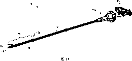
Figure 1A is the perspective view of a kind of embodiment of surgical stapling and cutter sweep, and the working end that demonstrates device is in initial position;
Figure 1B is the surgical stapling of Figure 1A and the perspective view of cutter sweep, and the working end that demonstrates device is in the position of carrying out joint motions;
Fig. 2 is the perspective view of the flexible neck of device shown among Figure 1A and the 1B;
Fig. 3 A is the perspective view of the distal part of device shown among Figure 1A and the 1B, shows flexible neck and the end effector of connected Fig. 2;
Fig. 3 B is the cutaway view along the line 3B-3B cross section of end effector shown in Fig. 3 A;
Fig. 4 A is the perspective view of the proximal part of device shown among Figure 1A and the 1B, shows the hands handle of the near-end of the axle that movably is connected to device;
Fig. 4 B is the exploded view of the proximal part of device shown among Fig. 4 A;
Fig. 5 is arranged on the flexible neck of device shown among Figure 1A and the 1B and the perspective view of the Connection Element between the slender axles, display optical image collecting device;
Fig. 6 is the perspective view of the handle of device shown among Figure 1A and the 1B, the display image display screen;
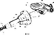
Fig. 7 is the perspective view that is used for the accessory channel of endoscope;
Fig. 8 A is the perspective view of the flexible neck of device shown among Fig. 7;
Fig. 8 B is the perspective view of the flexible neck that shows among Fig. 8 A, shows that neck carries out joint motions along first direction;
Fig. 8 C is the perspective view of the flexible neck that shows among Fig. 8 A, shows that neck carries out joint motions along second direction;
Fig. 9 A is the perspective view with the another kind of embodiment of the general flexible neck of described accessory channel;
Fig. 9 B is the perspective view of the flexible neck that shows among Fig. 9 A, shows that neck carries out joint motions along first direction;
Fig. 9 C is the perspective view of the flexible neck that shows among Fig. 9 A, shows that neck carries out joint motions along second direction;
Figure 10 is the perspective view of many cable actuators that is used for the device of Fig. 7;
Figure 11 be Fig. 7 accessory channel the axle cutaway view;
Figure 12 is a kind of perspective view of embodiment of end cap that is used for the accessory channel of Fig. 7;
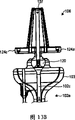
Figure 13 A is the handle of the slender axles that show among Fig. 7 and the exploded view of proximal part;
Figure 13 B is the handle of slender axles shown in Figure 13 A that is in the package assembly and the cutaway view of proximal part;
Figure 14 A is the perspective view of the another kind of embodiment of accessory channel;
Figure 14 B is the cutaway view of the accessory channel that shows among Figure 14 A;
Figure 15 A is the side view of the Handleset of device shown among Figure 14 A and the 14B;
Figure 15 B is the exploded view of the Handleset among Figure 15 A;
Figure 16 A is the perspective view of a kind of embodiment of locking mechanism; With
Figure 16 B is the perspective view of the locking mechanism of Figure 16 A of being connected with cutter sweep with the surgical stapling of Figure 1A and 1B.
The specific embodiment
Now some illustrative embodiments will be described, for the principle of structure, function, manufacturing and the use of apparatus and method disclosed herein provides comprehensive understanding.One or more examples of these embodiments are shown in the drawings.One of ordinary skill in the art will appreciate that special in this article the description and the determinate illustrative embodiments of apparatus and method right and wrong illustrated in the accompanying drawings, scope of the present invention is only limited by claims.The feature that illustrates and describe in conjunction with a kind of illustrative embodiments can with the characteristics combination of other embodiment.Be intended to some modifications and variations are included in the scope of the present invention.
The invention provides the method and apparatus that is used to control the endoscopic surgical device.Generally speaking, the endoscopic surgical device has slender axles, and the far-end working end and having that described slender axles have a band flexible neck is used to control the near-end of the movable handle of the flexible neck on the far-end working end.In some illustrative embodiments, this can use for example one or the many Suo Shixian that extend between handle and flexible neck, and the motion that makes handle is applied to power on one or the many ropes, causes the flexible portion deflection, thereby makes the working end motion of device.Various other parts also are provided, have been beneficial to the use of device.The particular configuration that it will be understood to those of skill in the art that controlled specific device and working end can change, and the various control technologys of describing in this article in fact all can be used in needing any surgical device of working end.
Figure 1A and 1B show a kind of illustrative embodiments of the technology that is used to control the end effector joint motions, especially for causing end effector imitation and the technology of moving simultaneously with handle.In this embodiment, device is to be used for a plurality of linear nails are applied being added to tissue and being used to cut the linearity stitching of the tissue that is sewn and the form of cutter sweep 10.As shown in the figure, device 10 generally includes the slender axles 12 with near-end 12a and far-end working end 12b, and handle 14 is connected with near-end 12a, and working end 12b has the end effector 16 (will go through below) that is connected or forms with it thereon.In use, end effector 16 is configured to imitate the motion of handle 14.Echokinesis between handle 14 and end effector 16 generally can realize that described actuator extends, and effectively power is transferred to end effector 16 from handle 14 by using the actuator (not shown) between handle 14 and end effector 16.In the exemplary embodiment, actuator is can be around circle spacing of slender axles 12 and many ropes that are provided with along the length of slender axles 12.Handle 14 is applied to one or many ropes around the motion of the near-end 12a of axle 12 with power, causes that rope is applied to end effector 16 with power, thereby causes the motion of end effector 16 imitation handles 14.Echokinesis can comprise corresponding motion, thereby makes end effector 16 along the direction identical with handle 14 with towards (orientation) motion, perhaps mirror movements, thus make end effector 16 along direction and the orientation movements opposite with handle 14.Echokinesis also can with the ratio that moves into of handle.
The slender axles 12 of device 10 can have multiple structure.For example, it can be solid or hollow, and can be formed by discrete component or a plurality of sections.As shown in Figure 2, slender axles 12 are hollow, and are formed by a plurality of continuous sections, to allow slender axles 12 deflections.Flexible and the less relatively diameter of axle 12 allows axle 12 to use in endoscopic surgery, thereby device is introduced through the chamber through natural orifice.The length of axle also can change, and this depends on the application of its expectation.
Fig. 2 also shows around circle spacing of slender axles 12 and is provided with and a kind of illustrative embodiments of the actuator 22 of many rope 34a, 34b extending along the length of slender axles 12,34c, 34d form.The number of rope and position can change.For example, these ropes can the about 120 ° of circumference settings around axle 12 of each interval.Every rope 34a-d extends through on slender axles 12, wherein or the passage that forms on every side, for example chamber.Fig. 2 shows the every rope 34a-d that extends through the cut-out that forms on the outer surface of each sections of axle 12.Therefore, each sections comprises four equidistant cut-outs around the circumference of axle 12, with the equidistant each other maintenance of rope 34a-d.Cut-out preferably has effectively rope 34a-d is limited in the size that wherein allows rope 34a-d to be free to slide with respect to axle 12 simultaneously.
The far-end of rope 34a-d can cooperate the motion with control end effector 16 with end effector 16.Though end effector 16 can have multiple structure, and various short end effector known in the art all can use, but Fig. 3 A shows a kind of illustrative embodiments of end effector, and it generally includes first and second jaws 18,20 that are suitable for tissue is contained in pair of opposing therebetween.First jaw 18 is suitable for comprising and has the nail bin that is arranged on wherein and is configured to be driven to a plurality of nails in the tissue, and second jaw 20 is formed for making the anvil block of nail distortion.The particular configuration of end effector 16 and basic operation can change, and various end effector 16 known in the art all can use.Example as indefiniteness, the U.S. Patent No. 6978921 that name is called " Surgical Stapling Instrument Incorporating an E-Beam FiringMechanism " discloses a kind of embodiment that can be used for end effector of the present invention, and its full content all is contained among the application.
In order to allow end effector 16 with respect to slender axles 12 motions, end effector 16 can movably engage with the far-end 12b of slender axles 12.For example, end effector 16 can pivot by pivot or swivel joint and be connected to the far-end 12b of slender axles 12.As an alternative, end effector 16 can comprise the flexible neck 26 that forms thereon, as shown in the figure, and to allow the motion of end effector 16 with respect to slender axles 12.Flexible neck 26 can form with the far-end 12b of slender axles 12 and/or the proximal body of jaw 18,20, and perhaps it can be the independent component that extends between axle 12 and jaw 18,20.As shown in FIG. 13A, flexible neck 26 comprise be used for flexible neck 26 be coupled to opposed jaws 18,20 near-end first connector 28 and be used for flexible neck 26 is coupled to second connector 30 of slender axles 12 far- ends.Connector 28,30 dismountable secure fit are to flexible neck 26 and/or jaw 18,20 and axle 12. Connector 28,30 also plays the effect of some elements that hold end effector 16.For example, first connector 28 can play rope is anchored on wherein effect (being discussed below), and it can also play to hold and be used for activating the gear of (for example close and pull the trigger) jaw 18,20 and the effect of driven unit.
The deflection of flexible neck 26 for convenience, neck 26 can comprise one or more slits 32 that form therein.The quantity of slit 32, position and size can change, with the flexibility that needing to obtain.In the embodiment that shows in Fig. 3 A, flexible neck 26 comprises many row's slits 32, and every row radially extends around flexible neck 26, and every row can be provided with along the length axially spaced-apart of flexible neck 26.Every row's slit comprises two slits around the circumferential extension of neck 26, and every row's slit 32 is axially staggered each other.As a result, flexible neck 26 comprises alternative slit 32.It will be understood by those skilled in the art that concrete graphic change of slit 32, Fig. 3 A only shows and is used to form a kind of graphic of the slit 32 that allows flexible neck 26 deflections.Other exemplary slit structure will go through below.
As mentioned above, rope 34a-d can be connected with end effector 16, to allow end effector 16 and handle 14 synergy movements.The link position of rope 34a-d and end effector 16 can change based on required motion.In the embodiment shown, the far-end of rope 34a-d is connected with the near-end of flexible neck 26, and particularly they extend in first connector 28 and with it and are connected.Fig. 3 B shows the cutaway view of first connector 28, shows to be respectively applied for four thorax hole 28a, 28b, 28c, the 28d that holds four rope 34a, 34b, 34c, 34d.In fact, any known technology in this area all can be used for rope 34a-d is connected to connector 28, comprises for example mechanical compounding technique (such as bonding, interference engagement, ball-and-socket connection, screw thread etc.).During use, when handle 14 is applied to rope 34a-d with axial force, rope 34a-d will allow rope 34a-d that tension force is applied to flexible neck 26 in the connection of the far-end of flexible neck 26.This tension force will cause that neck 26 is along by the amount of tension indicated direction deflection (will go through below) that is applied to every rope 34a-d.
Device 10 handle 14 can be used for controlling the motion of end effector 16, makes end effector 16 carry out joint motions when special, thereby with respect to the angled orientation of longitudinal axis A of slender axles 12.Though handle 14 can have multiple structure, handle 14 movably is connected to the near-end 12a of slender axles 12 in a kind of illustrative embodiments, and the motion of handle 14 can be imitated by end effector 16.Though various technology all can be used for handle 14 movably is connected to axle 12, in the embodiment shown in Fig. 4 A-4C, between the near-end 12a of handle 14 and slender axles 12, form ball-and-socket and connect.As the clearest demonstration among Fig. 4 B, the near-end 12a of slender axles 12 is included in the nest 24 that wherein forms, and handle 14 is included in and forms and be configured to the rotatable hemisphere 13a that is placed in the nest 24 on its far-end.Nest 24 can be integrally formed with the near-end 12a of slender axles, and perhaps it can be by being connected to hollow shell 12c (as shown in the figure) the near-end 12a of slender axles 12.Hemisphere 13a also can be integrally formed with handle 14, and perhaps it can be the independent component that is connected with handle 14.For handle 14 movably being coupled to axle 12, the hemisphere 13a on the handle 14 can use the rope 34a-d that is connected (being discussed below) with handle 14 to be limited in the nest 24.But other compounding technique also can be used for handle 14 movably is coupled to axle 12.For example, ball 13a can be spherical and it can be captured in the spherical nest among the near-end 12a that is formed at slender axles 12, and perhaps co-operating member (such as pin) can extend so that ball 13a is limited in the nest 24 by ball 13a.Though Fig. 4 B shows at ball 13a that forms on the handle 14 and the nest 24 that forms in axle 12, ball-and-socket connects and can put upside down, and makes ball be arranged on the axle 12 and makes nest be positioned at handle 14.In addition, it will be understood to those of skill in the art that various other technology can be used for handle 14 and slender axles 12 near-end 12a can be movingly.
During use, handle 14 articulatables or with respect to axle 12 pivoting actions cause the motion of end effector 16 imitation handles 14.This can be connected with handle 14 by the near-end with rope 34a-d realizes.The link position of rope 34a-d and handle 14 can change based on required motion.In the embodiment shown, rope (only having shown three rope 34a in Fig. 4 A, 34b and 34c) extends through hollow shell 12c from slender axles 12, and passes from the groove that forms among hollow shell 12c or opening.The ball 13a of rope 34a-d on the handle 14 extends and is connected with distal face on the handle 14 of ball 13a then.In fact any technology known in the art all can be used for rope 34a-d is connected with handle 14, comprises for example mechanical compounding technique, such as bonding, and interference fit, screw thread etc.Shown in Fig. 4 A, handle 14 is included in the opening that wherein forms, and the near-end (not shown) of rope 34a-d can have ball or other element that forms and be trapped in the opening thereon.Fig. 4 A shows that also rope (only having shown three rope 34a in Fig. 4 A, 34b and 34c) can keep the circumferential interval around handle 14.This motion that can allow handle 14 will be by end effector 16 mirror images (will go through below).As an alternative, rope 34a-d can they with intersect before handle 14 is connected, move along the direction identical to cause end effector 16 with handle 14.For example, the rope 34a that is oppositely arranged and 34c can be intersected with each other and be connected with the opposite side of handle 14, and the rope 34b that is oppositely arranged and 34d can be intersected with each other equally and can be connected with the opposite side of handle 14.Rope 34a-d can intersect in any position, in the hollow shell 12c on the near-end 12a of axle 12.
Fig. 4 A and 4B show that also handle 14 also can comprise other part, are beneficial to the use of device.For example, handle 14 can comprise the translation member 38 of the jaw 18,20 of closing effectively on the end effector 16 and effective as selective rotation and actuation end executor's 16 rotating parts 40.Translation and rotating parts 38,40 are described in detail in the patent application of being submitted to by people such as Mark Ortiz that is entitled as " Surgical Fastener And Cutter With Single Cable Actuator ", the applying date is identical with the application, and its content is contained among the application by reference and in full.In other embodiment, handle 14 can comprise trigger, knob etc., is used for rotation and/or actuation end executor 16.
Still with reference to Figure 1B, in use, handle 14 can pivot or angled orientation with respect to the near-end 12a of slender axles 12, so that end effector 16 carries out echokinesis.Particularly, handle 14 pivots around slender axles 12 along first direction, power is applied to one or many rope 34a-d goes up with axial pulling rope.As a result, the rope of actuating is applied to flexible neck 26 with tension force, causes neck 26 deflections.In order to prevent slender axles 12 corresponding to the tension force deflection that is applied to rope 34a-d by handle 14, flexible neck 26 can have the flexibility bigger than slender axles 12.This can be for example by using foregoing alternately slit 32 to realize that perhaps material can be different in other embodiments, and perhaps slender axles can comprise stable element, such as passing the bar that wherein extends, make slender axles have more rigidity than flexible neck.
The direction of motion of handle 14 can be imitated along equidirectional (being corresponding sports) or rightabout (being mirror movements) by end effector 16, thereby allows the user accurately to control the position of end effector 16.In the exemplary embodiment, the specified quantitative of end effector 16 motions can be proportional with the quantity of motion of handle 14.That is to say that the quantity of motion of end effector 16 can equate with the quantity of motion of handle 14 directly that perhaps it can be with respect to proportional increase of the quantity of motion of handle 14 or minimizing.In some embodiments, the quantity of motion that makes end effector 16 is ideal with respect to the quantity of motion increase of handle 14.As a result, only need the little motion of handle 14 to allow end effector 16 large amount of exercise.Though various technology can be used for realizing the proportional multiplication or the increase of end effector 16 motions, a kind of illustrative embodiments of power multiplication mechanism is the eccentric cam that is connected with rope, described eccentric cam can increase the mechanical advantage of rope 34a-d when tension force is applied to rope 34a-d by handle 14, or power or displacement.
It will be understood to those of skill in the art that though the motion between the working end of handle and device in theory can be proportional, in practice, because some losses of power may take place when being transmitted through slender axles in power.Therefore, the proportional motion of using in this article attempts to comprise that wherein handle and working end are configured to measure motion in proportion but the application of losing that some power can take place in the real-world operation process of device.
Various device disclosed herein also can comprise various other parts, to make things convenient for its use.For example, the device 10 of Figure 1A can comprise be arranged on the slender axles 12 and be formed at endoscopic surgery during the optical imagery collecting unit of images acquired.Though this unitary position can change, the optical imagery collecting unit can be arranged on second connector 30 in one embodiment.Particularly, Fig. 5 shows beveled shell 42, and is outstanding from the outer surface of connector 30, wherein accommodates the optical imagery collecting unit.On the distal face of shell 42, be formed with form 44, with allow described unit gather the end carry out limit 16 and around can be transferred to external image display panel with the image of operative site from the image of optical imagery collecting unit, perhaps as an alternative, device 10 can comprise on the proximal part that is arranged on device or connected image display panel.Fig. 6 shows from a kind of embodiment of the handle 14 outside image display panels of giving prominence to 46.
As previously mentioned, the various technology that are used to control the working end of endoscopic surgical device disclosed herein can be used in combination with various medical apparatus.Fig. 7 shows the another kind of embodiment of the medical apparatus with the motion that is used to control its working end.In this embodiment, medical apparatus is the form that is used for the accessory channel 100 of endoscope.Accessory channel 100 is can cooperate with endoscope and along the external device of its slip, allow other instrument such as nipper, and sickle etc. pass near the observation end of wherein introducing and be positioned at endoscope.Though in fact accessory channel 100 can have various structures, shape and size in embodiment shown in Figure 7, accessory channel 100 comprises elongated tubular or axle 102, and it has between its near-end and far-end 102a, 102b and to extend, to be used for instrument is contained in therebetween inner chamber.Accessory channel 100 also can comprise the co-operating member that forms thereon, is used for accessory channel 100 directly being engaged in endoscope or being arranged on endoscope's sleeve or other device on every side.Though in fact any compounding technique all can use, in the embodiment shown, the co-operating member on the accessory channel 100 is the form along the guide rail 104 of the length extension of slender axles 102.Guide rail 104 is configured to be contained in endoscope or goes up in the complementary rails that forms around the device (for example sleeve) that endoscope is provided with.It will be understood to those of skill in the art that various other technology all can be used for accessory channel directly or indirectly is engaged in the endoscope.
For the motion of the working end of controlling accessory channel 100, device 100 can comprise and is similar to previously described those parts.Particularly, the far-end 102a that device 100 can be included in slender axles 102 goes up formation or connected flexible neck 108, forms or connected handle 106 on the near-end 102a of slender axles 102, and the actuator that extends between handle 106 and flexible neck 108.In this embodiment, actuator is configured to from handle 106 power is transferred to flexible neck 108, and the motion of handle 106 is imitated by flexible neck 108, thus allow to pass instrument that accessory channel 100 extends be positioned in required angle towards.
Flexible neck 108 can have various structures, and it can make the independent component that is connected with slender axles 12, perhaps its can with slender axles 102 whole formation, as shown in Figure 7.It is flexible that neck 108 can use various technology to produce.For example, neck 108 can be formed by one or more sections that move relative to each other, and/or it can be formed by flexible material.In the illustrative embodiments shown in Fig. 8 A, neck 108 is included in a plurality of slits 112 that wherein form and be configured to provide the greatest flexibility of neck 108.Though the size of slit 112, quantity and towards changing the result who needs to obtain, flexible neck 108 comprises four row slits (only having shown three row slits, by arrow 112a, 112b, 112c indication) in the embodiment shown.Every row extend axially along the length of flexible neck 108, and every row comprise the four row's slits that are provided with around the circumference axially spaced-apart of neck 108.Every row slit 112 is also axially interlaced with each other, to allow slit 112 stacked.During use, when tension force is applied to actuator, slit 112 will allow neck 108 bendings or take curved configuration, make neck 108 carry out joint motions with respect to the remainder of slender axles 102, shown in Fig. 8 A and 8C.
In other embodiment, slit can be oriented to allow the neck deflection in the precalculated position.As the example of indefiniteness, Fig. 9 A shows the another kind of embodiment of the flexible neck 108 ' in two zones that are formed with slit 112 ' therein.Particularly, flexible neck 108 ' comprises the distal region 112a ' of slit and the proximal end region 112b ' of slit.Each regional 112a ', 112b ' can comprise the slit of any number that is positioned at any position, to provide required flexible degree along one or more required directions.Shown in Fig. 9 A, the distally of slit and proximal region 112a ', 112b ' comprise that respectively two come the slit that forms on the opposite side of flexible neck 108 ' and extend along its length.During use, when tension force is applied to flexible neck 108 ' (will go through below), neck 108 ' will be at distally and far and near lateral areas territory 112a ', two all deflections of zone of 112b ', thus carry out joint motions with respect to the remainder of slender axles 102 '.Shown in Fig. 9 B, deflection can at first take place in the distal region 112a ' of neck 108 '.Further be applied to 108 ' tension force and can cause then deflection takes place among the proximal end region 112b ', shown in Fig. 9 C.In other embodiment, the size of slit location and/or slit can be formed at before deflection takes place in distal region 112a ', cause that deflection takes place in proximal end region 112b ', perhaps as an alternative, slit can be configured to cause among nearside and distal region 112b ', the 112a ' and take place simultaneously.It will be understood to those of skill in the art that quantity, position, the size and dimension scalable of slit, to obtain required result.The concrete structure that is used to form the otch of slit also is variable.For example, the width of slit and length can be consistent on that surface from the outer surface of slender axles to slender axles, and perhaps as an alternative, width and length can increase or reduce, and slit are tapered or other variation.As the example of indefiniteness, tapered structure can form by the slit that formation has a triangular construction, and wherein the length of slit and width reduce to inner surface from the outer surface of slender axles.
As mentioned above, actuator is configured to tension force is applied on the flexible neck 108, causes that neck 108 carries out joint motions.Actuator can have multiple structure, but actuator is similar to aforementioned actuator in a kind of illustrative embodiments, and comprises one or more ropes that extend between the far-end of handle 106 and flexible neck 108, and handle 106 and flexible neck 108 are associated in operation.Every rope can be configured to tension force is applied to flexible neck 108, causes that neck 108 carries out joint motions in plane of movement.Therefore, when device 100 only comprised a rope, flexible neck 108 can carry out joint motions in single plane of movement.Each additional rope can allow neck 108 to carry out joint motions in different plane of movement.When many ropes were provided, neck 108 can carry out joint motions in a plurality of plane of movement.In addition, rope can be applied in tension force simultaneously, can allow flexible neck 108 to carry out 360 ° joint motions.
Though the number of rope can change, install 100 and can only comprise a rope, in embodiment shown in Figure 7, device 100 comprises four ropes (only having shown three rope 110a, 110b, 110c).Rope 110a, 110b, 110c, 110d be more detailed demonstration in Figure 10.As mentioned above, rope 110a-d extends along the length of the slender axles 102 between handle 106 and the flexible neck 108.The particular location of rope 110a-d can change, but rope 110a-d radially is provided with at interval around the circumference of slender axles 102 in the exemplary embodiment, and they extend between the distal-most end of flexible neck 108 and handle 106.Rope 110a-d can be by the inside of slender axles 102 or along slender axles 102 outside extensions, and perhaps they can be passed in chamber or the passage extension that forms in the sidewall of slender axles 102.Figure 11 shows the cutaway view of slender axles 102, is presented at four chamber 103a, the 103b, 103c, the 103d that wherein form.Chamber 103a-d preferably has the size that allows rope 116a-d to slide therein, and they circumferentially are provided with at interval around slender axles 102.Chamber 103a-d extends between the near-end 102a of slender axles 102 and far-end 102b, allows rope 110a-d to extend between the distal-most end of handle 106 and flexible neck 108.
The far-end of rope 110a-d can use various technology to cooperate with the distal-most end of flexible neck 108, but in a kind of embodiment that shows in Figure 12, flexible neck 108 comprises the end cap 114 that is connected or forms with its distal-most end thereon.Though the structure of end cap 114 can be based on the structure of actuator and is changed, end cap 114 is included in and wherein forms and around four thorax hole 114a, 114b, 114c, 114d that circle spacing of end cap 114 is provided with in the embodiment shown, and thorax hole 114a-d is aimed at chamber 103a-d in the slender axles 102.Each thorax hole 114a-d is configured to hold wherein rope 110a-d.Various compounding techniques all can be used for rope 110a-d is remained among the 114a-d of thorax hole.For example, Figure 10 shows the ball that forms on the end of every rope 110a-d, is used for the end of rope 110a-d is remained among the thorax hole 114a-d of end cap 114.End cap 114 also can be included in the central chamber 116 that wherein forms, and is used for instrument is contained in wherein.Chamber 116 also can be used for the convenient tool positioned of inserting through accessory channel 100.
The near-end of rope 110a-d can cooperate with the handle 106 of the near-end that is connected to axle 102.Though handle 106 can have multiple structure, in a kind of illustrative embodiments that shows among Fig. 7 in front, handle 106 can be the stick form that movably is connected with the near-end 102a of slender axles 102, particularly is configured to carry out joint motions with respect to the near-end of slender axles 102.The joint motions of handle 106 can allow the motion of handle 106 by flexible neck 108 imitations (will inquire into below).
Though joint motions can use polytype union joint to realize, in the embodiment shown, between handle 106 and slender axles 102, form ball-and-socket and connect.Particularly, as more detailed demonstration among Figure 13 A and the 13B, the near-end 102a of slender axles 102 comprises the shell 103 that forms and limit a nest 118 thereon in its near-end.Handle 106 comprises the ball 120 that movably is arranged in the nest 118, and stick from ball 120 to proximal extension, thereby allow handle 106 to carry out joint motions with respect to slender axles 102.Pin or other mechanism can be used to ball 120 is movably remained in the nest 118.It will be understood to those of skill in the art that handle can have various other shapes, and various other technology can be used for all handle 106 movably is connected to slender axles 102.
As mentioned above, the near-end of rope 110a-d is configured to cooperate with handle 106.Therefore, handle 106 can comprise the part that is used to be coupled to rope 110a-d.Though concrete mating parts can change based on the structure of actuator, in the exemplary embodiment, the stick 122 on the handle 106 comprises four lower limb 124a, 124b, 124c, the 124d that forms thereon.Lower limb 124a-d they are roughly aimed at rope, and each lower limb 124a-d is configured to cooperate with the terminal of one of them rope 110a-d around the circle spacing setting of stick 122.As previously mentioned, the ball-and-socket connection of the far-end of rope 110a-d explanation can be used for making rope 110a-d to cooperate with lower limb, perhaps as an alternative, can use any other known compounding technique.
Still with reference to Fig. 7, in use, handle 106 can pivot or angled orientation with respect to the near-end 102a of slender axles 102, so that flexible neck 108 carries out echokinesis, thereby the instrument that flexible neck 108 extends is passed in the location.Shown in Fig. 7 and 13B, the stick on the handle 106 can comprise pass wherein form and with slender axles 102 in the aligned chamber 107 of chamber 102c, the permission instrument is introduced by device 100.In other embodiments, handle 106 can make handle 106 be connected with rope, but not influence the chamber 102c in the direct contact slender axles 102 from the near-end 102a biasing of slender axles 102.
Also control the wherein localized instrument that passes thus for the motion of controlling flexible neck 108, handle 106 centers on the near-end 102a pivot of slender axles 102 or carries out joint motions.For example, handle 106 will cause that along moving of first direction the lower limb 124a-d on the handle 106 is applied to power on one or the many rope 110a-d, with axial pulling rope.As a result, the rope of actuating is applied to flexible neck 108 with tension force, causes neck 108 deflections.In order to prevent slender axles 102 deflection in response to the tension force that is applied to rope 110a-d by handle 106, flexible neck 108 can have the flexibility bigger than slender axles 102.For example, this can adopt foregoing slit to realize, perhaps axle 102 can comprise and passes wherein the stable element that extends in other embodiments, such as bar, makes axle 102 have more rigidity than flexible neck 108.The direction of motion of handle 106 will be by flexible neck 108 with equidirectional (promptly corresponding motion) or (being mirror image) imitation in the opposite direction, thereby the position of the instrument that flexible neck 108 extends is passed in control.In the exemplary embodiment, the concrete quantity of motion of flexible neck 108 can be proportional with the quantity of motion of handle 106.That is to say that the quantity of motion of flexible neck 108 can directly equate that perhaps it can be with respect to proportional increase of the quantity of motion of handle 106 or minimizing with the quantity of motion of handle 106.In some embodiments, the quantity of motion that it is desirable to flexible neck 108 can increase with respect to the quantity of motion of handle 106.As a result, only need the little quantity of motion of handle 106 to make flexible neck 108 carry out the greater amount motion.Though various technology can be used for realizing the proportional multiplication or the increase of flexible neck 108 motions, a kind of illustrative embodiments of power multiplication mechanism is the eccentric cam that is connected with rope, this cam can increase the mechanical advantage of rope 110a-d when tension force is applied to rope 110a-d by handle 106, or power or displacement.
As previously mentioned, though the motion between the working end of handle and device in theory can be proportional, in practice, some losses of power may take place when being transmitted through slender axles owing to power.Therefore, the proportional motion of using in this article attempts to comprise that wherein handle and working end are configured to measure motion in proportion but the application of losing that some power can take place in the real-world operation process of device.
Though Figure 1A and 7 shows the device of the imitation of working end wherein handle motion, handle can have that joint motions are carried out in the working end that can effectively make device and multiple other structure of motion that can not make the working end imitation handle of device.Figure 14 A and 14B show the another kind of embodiment of the device 200 with handle 204, and described handle comprises the rotating parts that effectively makes flexible neck 206 carry out joint motions along one or more plane of movement with respect to the slender axles 202 that install.Generally speaking, the slender axles 202 and the aforementioned slender axles 102 of device 200 are closely similar, and it generally includes the flexible neck 206 that is connected or forms with its far-end thereon.Four cable actuator (not shown)s extend through the slender axles between handle 106 and the flexible neck 206.Axle 102 and cable actuator are similar to axle 102 and the cable actuator 110a-d that front comparable device 100 is described, and therefore will no longer be described in detail them.
Handle 204 more detailed demonstration in Figure 15 A and 15B of device 200.Generally speaking, handle 204 comprises one or more rotatable reels that are arranged on wherein.Each reel is configured to be coupled to one of them cable actuator and it is controlled.Therefore, rope will be reeled or discharge to the rotation of each reel, thereby cause flexible neck 108 deflections and activate along specific direction.Though the number of reel can change based on cable actuator, in the embodiment shown in Figure 15 A and the 15B, handle 204 comprises four reel 208a, 208b, 210a, 210b.Two reel 208a, 208b of front are connected to each other, and two reel 210a, 210b of back are connected to each other.The first rope 212a is connected with the first reel 208a and reels on it, and the second rope 212b is connected with the second reel 208b and reels thereon.The first and second rope 212a, 212b are positioned in the opposite side of slender axles 202 and go up and along its extension.The result, the tension force that is applied on the first rope 212a will cause that flexible neck 206 carries out joint motions along a direction in first plane of movement, and the tension force that is applied on the second rope 212b will cause that flexible neck 206 carries out joint motions in the opposite direction in second plane of movement.In order to allow tension force only to be applied among rope 212a, the 212b one, the first and second rope 212a, 212b reel around the first and second reel 208a, 208b in the opposite direction.Therefore, the rotation of the first and second reel 208a, 208b with coiling rope 212a among the 212b one and to and apply tension force, make among rope 212a, the 212b another open and remove tension force simultaneously.The third and fourth rope 212c, 212d reel around the third and fourth reel 210a, 210b equally, the rotation of the third and fourth reel 210a, 210b will make among rope 212c, the 212d one to reel and tension force is applied thereto, and open among rope 212c, the 212d another simultaneously and also remove tension force.The third and fourth rope 212c, 212d can extend in the position of radially staggering with the first and second rope 212a, 212b along axle 202, make the third and fourth rope 212c, 212d cause that flexible neck carries out joint motions along the second different plane of movement.For example, the third and fourth rope 212c, 212d can stagger about 90 ° with the first and second rope 212a, 212b, the distance that the circumference that makes rope 212a-d all center on slender axles 202 roughly equates at interval.It will be understood to those of skill in the art that handle 204 can comprise the reel and the rope of any amount, carries out joint motions with the number of planes along needs.
In order to control reel 208a, 208b, 210a, 210b, device can comprise one or more clamping components.Shown in Figure 15 A and 15B, first knob 214 is connected with the first and second reel 208a, 208b, and second knob 216 is connected with the third and fourth reel 210a, 210b.Knob 214,216 can form with reel 208a, 208b, 210a, 210b integral body, and perhaps they can be connected with reel 208a, 208b, 210a, 210b by the axle that passes reel 208a, 208b, 210a, 210b extension.In the embodiment shown, first knob 214 directly forms on the first reel 208a or is connected with it, and second knob 216 can be connected with the third and fourth reel 210a, 210b by the axle 218 that extends from the knob 216 that passes the first and second reel 208a, 208b and be connected to the third and fourth reel 210a, 210b.In other words, the first and second reel 208a, 208b are around axle 218 rotary setting.
In some illustrative embodiments, reel and knob also can have different size.In the embodiment shown in Figure 15 A and the 15B, the first and second reel 208a, 208b and first knob 214 have the big diameter of diameter than the third and fourth reel 210a, 210b and second knob 216.Though not necessarily, described structure is advantageously, because it is spaced apart with rope 212a-d, has prevented that rope 212a-d from contacting with each other.
During use, instrument is positioned through slender axles 202, and knob 214,216 is rotatable, makes flexible neck 206 carry out joint motions on axle 202, thus orientation tool as required.Shown in Figure 14 A and 14B, handle 204 can comprise pass wherein extend and with slender axles 202 in aligned chamber 205, chamber, the permission instrument passes handle 204 and axle 202.In other embodiment, handle 204 can stagger with slender axles 202, so that the direct import of slender axles 202 lumens to be provided.In case instrument is positioned through axle 202, knob 214,216 is rotatable, makes flexible neck 206 carry out joint motions on the far-end of slender axles 202.Particularly, first knob 214 can be along first direction (for example along clockwise direction) rotation, tension force is applied to a rope (for example second rope 212a), discharges simultaneously or opens another rope (for example second rope 212b).As a result, the tension force that is applied to the first rope 212a will spur the distal-most end of flexible neck 206 along proximal direction, cause flexible neck 206 deflections and carry out joint motions along first direction thus.() rotation for example counterclockwise will be opened the first rope 212a, the second rope 212b that reels simultaneously in the opposite direction the rotation of first knob 214.Flexible neck 206 will return to its initial lineament.Being further rotated the continuation coiling second rope 212b of first knob 214 opened the first rope 212a simultaneously, thereby caused flexible neck 206 deflections and carry out joint motions in the opposite direction in identical plane of movement.Second knob 216 can rotate equally, makes flexible neck carry out joint motions in the different motion plane.Knob 214,216 also can randomly rotate simultaneously, makes flexible neck 206 carry out joint motions in the other plane of movement different with first and second plane of movement.
In other embodiments, various device disclosed herein can comprise be used for handle and/or actuator be locked in the fixed position with working end that will device remain on required joint motions or angle towards locking mechanism.Though locking mechanism can have various structures, locking mechanism can be the form of anchor clamps in a kind of illustrative embodiments, thus its effectively clamp on rope, prevent the motion of rope so that along needs towards the locking working end.Anchor clamps can have different shape and size, and it can be positioned in all places on the device.Figure 16 A and 16B show a kind of illustrative embodiments of anchor clamps 300, and the hollow shell 12c on the fastening and cutter sweep 10 of its surgery around Figure 1A and 1B is provided with.Anchor clamps 300 are generally annular and can be configured to and cooperate with the hollow shell 12c slip or the rotation of adjacent openings, and rope (only having shown rope 34a, 34b, 34c in Figure 16 B) can pass described opening and extend.At initial position, anchor clamps 300 are provided with at interval with opening, allow rope 34a-d to pass wherein freely-movable.In case working end, for example end effector 16 of device carry out joint motions along required direction, anchor clamps 300 can be along hollow shell 12c axially-movable, extends above opening and engages with the rope 34a-d that extends through wherein up to it.When anchor clamps 300 are in the latched position, anchor clamps 300 will prevent the motion of rope 34a-d thus.In order to make anchor clamps 300 axially-movables and anchor clamps 300 to be locked among the shell 12c, anchor clamps 300 can comprise the co-operating member that forms and be configured to engage with the corresponding co-operating member that forms thereon on shell 12c.Shown in Figure 16 A and 16B, anchor clamps are included in the screw thread 302 that wherein forms, and it is configured to cooperate with the respective threaded (not shown) that forms on shell 12c.As a result, anchor clamps 300 will cause that around the rotation of shell 12c anchor clamps 300 move between initial position and latched position.It will be understood to those of skill in the art that various other compounding techniques also can use.For example, handle can comprise forming thereon and being configured to handle lock is fixed on locking member in the fixed joint motions position.
In other embodiments, rope can be used for allowing passively slender axles to carry out joint motions through body cavity, and when needed anchor clamps 300 or other locking mechanism can be used for will device the working end be locked in the position.In the structure of this class, handle can only be used to make things convenient for the clamping of device.
In other embodiments, the disclosed in this article working end that is used to the to make device cable actuator that carries out joint motions can be made by the electroactive polymer material.Electroactive polymer (EAP) (being also referred to as artificial muscle) is in response to electric field or chemical fields shows the material that piezoelectricity, thermoelectricity or electricity cause characteristic.Particularly, EAP is one group of adulterated conducting polymer, and its shape changes when applying voltage.Conducting polymer can be that pairing forms ion fluid or gel and electrode, but enters or the ion flow induced polymer shape that flows out conducting polymer changes from fluid/gel.Typically, depend on that the particular polymers of use and ion flow or gel apply the voltage of about 1V in the 4kV scope, what pay particular attention to is when energize, and EAP does not change volume, and they only expand and contraction in the opposite direction along a direction.Therefore, the disclosed in this article cable actuator in front can be replaced by the EAP actuator, and handle can be configured to activate the energy, with optionally with energy delivery to or many ropes.In the exemplary embodiment, the motion of handle can be configured to control the amount of the energy and the energy that rope receives.As a result, the motion of handle still can be by the working end of device imitation, for the user provides identical accurate control to the position, working end.The energy can be inside sources (for example battery), perhaps also can be external source.In other embodiments, the EAP cable actuator can replenish motion by handle and be applied to axial force on the rope, thereby with respect to the quantity of motion of the proportional increase of handle working end.
In others, cable actuator can be made by shape-memory material, for example Nitinol.Described structure allows tension force to be applied to rope, makes end effector carry out joint motions, also allows rope to be returned to initial lineament, and does not need operating grip.
In another embodiment, various devices disclosed herein comprise its part, can be designed to be abandoned after once using, and perhaps they can be configured to repeatedly use.In either case, after at least one used, device can be reproduced so that reuse.Regeneration can comprise the fractionation of any device, then the step combination of cleaning or replacement specific features and assembling subsequently.As an example, surgical stapling shown in Figure 1A and the 1B and cutter sweep can use back regeneration at device in medical surgery.Device can split, and the specific features of arbitrary number can optionally be replaced or be removed in any combination.For example, for surgical stapling and cutter sweep, be arranged in the end effector and the nail bin that contains a plurality of securing members can be replaced by new securing member storehouse is increased in the end effector.When cleaning and/or replacement specific features, device can be re-assemblied the use that is used for subsequently immediately in the regeneration workshop or by surgery team before surgical operation.The regeneration that it will be understood to those of skill in the art that device can utilize various assembling, cleaning/replacement and the recombinant techniques of being used for.The regenerating unit that uses and produce of described technology all belongs to the application's scope.
Based on above-mentioned embodiment, it will be understood to those of skill in the art that other features and advantages of the present invention.Therefore, unless specialized by appending claims, what the present invention can't help to have shown and described especially limits.All publications and the list of references quoted in this article all comprise in this application clearly by quoting in full.
Claims (10)
1. accessory channel that is used for releasably being connected to endoscope, described accessory channel comprises:
Elongated tubular has the inner chamber that passes its extension between its near-end and far-end, is used to hold instrument;
Flexible neck begins to extend and can deflection from the far-end of described elongated tubular, so that guiding extends through the instrument of described elongated tubular: and
Handle, be connected to described elongated tubular near-end and the operation on be associated with described flexible neck, thereby make described flexible neck imitate the motion of described handle.
2. accessory channel as claimed in claim 1, wherein, described flexible neck comprises a plurality of slits that are formed at wherein, so that its deflection.
3. accessory channel as claimed in claim 2, wherein, described flexible neck comprises the proximal region of the distal region and the slit of slit, and described slit is constructed such that the tension force that is applied on the described flexible neck causes described flexible neck in described proximal region and distal region bending.
4. accessory channel as claimed in claim 1, wherein, described handle comprises fixed component and the movable link that can carry out joint motions with respect to described fixed component.
5. accessory channel as claimed in claim 4, wherein, described movable link is connected to described fixed component by joint, and described joint is selected from the group of being made up of ball-and-socket joint, articulated joint and flexible joint.
6. accessory channel as claimed in claim 1 also is included in the actuator that extends between described handle and the described flexible neck, and described actuator can be delivered to described flexible neck from described handle with motion.
7. accessory channel as claimed in claim 6, wherein, described actuator comprises at least one rope that extends along the length of described elongated tubular.
8. accessory channel as claimed in claim 7 also comprises locking mechanism, and this locking mechanism is positioned to engage with in described handle and the described at least one rope at least one, so that described handle and described at least one rope are locked in the fixed position.
9. accessory channel as claimed in claim 7, wherein, described at least one rope comprises many ropes, these ropes equally spaced separate each other along the circumference of described elongated tubular.
10. accessory channel as claimed in claim 7, wherein, described elongated tubular comprises and being formed in its sidewall and along at least one chamber that its length is extended, and described at least one actuator is slidably disposed on described at least one intracavity.
Applications Claiming Priority (2)
| Application Number | Priority Date | Filing Date | Title |
|---|---|---|---|
| US11/277,324 US20070225562A1 (en) | 2006-03-23 | 2006-03-23 | Articulating endoscopic accessory channel |
| US11/277,324 | 2006-03-23 |
Publications (1)
| Publication Number | Publication Date |
|---|---|
| CN101040772A true CN101040772A (en) | 2007-09-26 |
Family
ID=38596492
Family Applications (1)
| Application Number | Title | Priority Date | Filing Date |
|---|---|---|---|
| CN 200710089656 Pending CN101040772A (en) | 2006-03-23 | 2007-03-23 | Articulating endoscopic accessory channel |
Country Status (5)
| Country | Link |
|---|---|
| JP (1) | JP5449653B2 (en) |
| CN (1) | CN101040772A (en) |
| AU (1) | AU2007201204B2 (en) |
| BR (1) | BRPI0704599A (en) |
| MX (1) | MX2007003575A (en) |
Cited By (14)
| Publication number | Priority date | Publication date | Assignee | Title |
|---|---|---|---|---|
| CN101791247A (en) * | 2010-04-01 | 2010-08-04 | 天津大学 | Surgical instrument with degrees of freedom for minimally invasive surgery |
| CN102132225A (en) * | 2008-08-14 | 2011-07-20 | 曼特瑞斯医药公司 | Stereotactic drive system |
| US8747418B2 (en) | 2008-08-15 | 2014-06-10 | Monteris Medical Corporation | Trajectory guide |
| US8979871B2 (en) | 2009-08-13 | 2015-03-17 | Monteris Medical Corporation | Image-guided therapy of a tissue |
| US9333038B2 (en) | 2000-06-15 | 2016-05-10 | Monteris Medical Corporation | Hyperthermia treatment and probe therefore |
| US9433383B2 (en) | 2014-03-18 | 2016-09-06 | Monteris Medical Corporation | Image-guided therapy of a tissue |
| US9504484B2 (en) | 2014-03-18 | 2016-11-29 | Monteris Medical Corporation | Image-guided therapy of a tissue |
| CN106572783A (en) * | 2014-01-24 | 2017-04-19 | 皇家飞利浦有限公司 | Robotic actuator for transeopagel echocardiography probe |
| CN108348142A (en) * | 2015-11-20 | 2018-07-31 | 波士顿科学国际有限公司 | The actuation handle of auxiliary device |
| US10327830B2 (en) | 2015-04-01 | 2019-06-25 | Monteris Medical Corporation | Cryotherapy, thermal therapy, temperature modulation therapy, and probe apparatus therefor |
| CN109925060A (en) * | 2017-12-15 | 2019-06-25 | 中国人民解放军第二军医大学 | A kind of bionic surgical Instrument and its control method |
| US10675113B2 (en) | 2014-03-18 | 2020-06-09 | Monteris Medical Corporation | Automated therapy of a three-dimensional tissue region |
| CN113507893A (en) * | 2018-12-31 | 2021-10-15 | 西拉格国际有限公司 | Cartridge-receiving jaws for surgical staplers and related methods of manufacture using MIMs |
| WO2022126461A1 (en) * | 2020-12-17 | 2022-06-23 | Covidien Lp | Articulation and articulation lock features for articulating surgical instruments such as endoscopes |
Families Citing this family (20)
| Publication number | Priority date | Publication date | Assignee | Title |
|---|---|---|---|---|
| KR100911248B1 (en) * | 2007-10-17 | 2009-08-07 | 국립암센터 | Small caliber laparoscope surgical apparatus |
| GB2456165A (en) * | 2008-01-04 | 2009-07-08 | Gyrus Medical Ltd | Slotted, flexible shaft for an endoscopic instrument |
| DE102008015418A1 (en) * | 2008-03-20 | 2009-09-24 | Richard Wolf Gmbh | Medical instrument |
| US9314308B2 (en) | 2013-03-13 | 2016-04-19 | Ethicon Endo-Surgery, Llc | Robotic ultrasonic surgical device with articulating end effector |
| JP6132904B2 (en) * | 2013-03-29 | 2017-05-24 | オリンパス株式会社 | Master-slave system and its operation method |
| DE102013214278A1 (en) | 2013-07-22 | 2015-01-22 | Digital Endoscopy Gmbh | SEALING COMPONENT FOR AN ENDOSCOPE PLUG |
| DE102013222041A1 (en) * | 2013-10-30 | 2015-04-30 | Digital Endoscopy Gmbh | Deflection movement transmission device, endoscope deflecting control and endoscope |
| DE102013222039A1 (en) * | 2013-10-30 | 2015-04-30 | Digital Endoscopy Gmbh | Attachable to a mother endoscope secondary endoscope and combination of mother endoscope and secondary endoscope |
| DE102013222042A1 (en) | 2013-10-30 | 2015-04-30 | Digital Endoscopy Gmbh | Deflection movement transmission device, endoscope deflecting control and endoscope |
| DE102013224683A1 (en) | 2013-12-02 | 2015-06-03 | Digital Endoscopy Gmbh | ENDOSCOPIC HEAD AND ENDOSCOPE |
| DE102013226591A1 (en) | 2013-12-19 | 2015-06-25 | Digital Endoscopy Gmbh | DEVICE AND METHOD FOR PRODUCING A PERMANENT HOLLOW PROFILE ELEMENT, LONG-TERM HOLLOW PROFILE ELEMENT AND AN ANCIENT UNIT FOR AN ENDOSCOPE |
| JP6284182B2 (en) * | 2014-01-08 | 2018-02-28 | 国立大学法人九州大学 | Operation unit for bending treatment tools |
| EP3094271B1 (en) * | 2014-01-13 | 2020-01-01 | Arthrex, Inc | Steerable surgical device with joystick |
| DE102014201208A1 (en) | 2014-01-23 | 2015-07-23 | Digital Endoscopy Gmbh | FLUID BLOCK FOR AN ENDOSCOPE PART AND ENDOSCOPE |
| DE102014201286B4 (en) | 2014-01-24 | 2019-12-24 | Digital Endoscopy Gmbh | METHOD AND DEVICE FOR TRACKING THE BASIC FREQUENCY OF A VOICE SIGNAL IN REAL TIME |
| EP3244958B1 (en) * | 2015-05-07 | 2018-11-28 | St. Jude Medical, Cardiology Division, Inc. | Medical device including a variable torque assembly for device deflection |
| DE102015113016B4 (en) | 2015-08-07 | 2018-03-29 | Digital Endoscopy Gmbh | ENDOSCOPE HEAD |
| US11660106B2 (en) * | 2016-07-19 | 2023-05-30 | Cilag Gmbh International | Articulation joint having an inner guide |
| US11166773B2 (en) | 2016-09-09 | 2021-11-09 | Intuitive Surgical Operations, Inc. | Stapler beam architecture |
| US11672596B2 (en) * | 2018-02-26 | 2023-06-13 | Neuwave Medical, Inc. | Energy delivery devices with flexible and adjustable tips |
Family Cites Families (8)
| Publication number | Priority date | Publication date | Assignee | Title |
|---|---|---|---|---|
| WO1993013704A1 (en) * | 1992-01-09 | 1993-07-22 | Endomedix Corporation | Bi-directional miniscope |
| US7637905B2 (en) * | 2003-01-15 | 2009-12-29 | Usgi Medical, Inc. | Endoluminal tool deployment system |
| JP2002051974A (en) * | 2000-08-14 | 2002-02-19 | Fuji Photo Optical Co Ltd | Endoscope manipulator |
| US7431694B2 (en) * | 2003-05-16 | 2008-10-07 | Ethicon Endo-Surgery, Inc. | Method of guiding medical devices |
| US7090637B2 (en) * | 2003-05-23 | 2006-08-15 | Novare Surgical Systems, Inc. | Articulating mechanism for remote manipulation of a surgical or diagnostic tool |
| US7686826B2 (en) * | 2003-10-30 | 2010-03-30 | Cambridge Endoscopic Devices, Inc. | Surgical instrument |
| JP2005296412A (en) * | 2004-04-13 | 2005-10-27 | Olympus Corp | Endoscopic treatment apparatus |
| JP2005328882A (en) * | 2004-05-18 | 2005-12-02 | Olympus Corp | Treatment instrument for endoscope, and endoscopic system |
-
2007
- 2007-03-20 AU AU2007201204A patent/AU2007201204B2/en not_active Ceased
- 2007-03-22 JP JP2007075136A patent/JP5449653B2/en not_active Expired - Fee Related
- 2007-03-23 MX MX2007003575A patent/MX2007003575A/en active IP Right Grant
- 2007-03-23 CN CN 200710089656 patent/CN101040772A/en active Pending
- 2007-03-23 BR BRPI0704599 patent/BRPI0704599A/en not_active Application Discontinuation
Cited By (31)
| Publication number | Priority date | Publication date | Assignee | Title |
|---|---|---|---|---|
| US9333038B2 (en) | 2000-06-15 | 2016-05-10 | Monteris Medical Corporation | Hyperthermia treatment and probe therefore |
| US9387042B2 (en) | 2000-06-15 | 2016-07-12 | Monteris Medical Corporation | Hyperthermia treatment and probe therefor |
| USRE47469E1 (en) | 2008-08-14 | 2019-07-02 | Monteris Medical Corporation | Stereotactic drive system |
| US8728092B2 (en) | 2008-08-14 | 2014-05-20 | Monteris Medical Corporation | Stereotactic drive system |
| CN102132225A (en) * | 2008-08-14 | 2011-07-20 | 曼特瑞斯医药公司 | Stereotactic drive system |
| US8747418B2 (en) | 2008-08-15 | 2014-06-10 | Monteris Medical Corporation | Trajectory guide |
| US10610317B2 (en) | 2009-08-13 | 2020-04-07 | Monteris Medical Corporation | Image-guided therapy of a tissue |
| US8979871B2 (en) | 2009-08-13 | 2015-03-17 | Monteris Medical Corporation | Image-guided therapy of a tissue |
| US9211157B2 (en) | 2009-08-13 | 2015-12-15 | Monteris Medical Corporation | Probe driver |
| US9510909B2 (en) | 2009-08-13 | 2016-12-06 | Monteris Medical Corporation | Image-guide therapy of a tissue |
| US9271794B2 (en) | 2009-08-13 | 2016-03-01 | Monteris Medical Corporation | Monitoring and noise masking of thermal therapy |
| US10188462B2 (en) | 2009-08-13 | 2019-01-29 | Monteris Medical Corporation | Image-guided therapy of a tissue |
| CN101791247A (en) * | 2010-04-01 | 2010-08-04 | 天津大学 | Surgical instrument with degrees of freedom for minimally invasive surgery |
| US10548678B2 (en) | 2012-06-27 | 2020-02-04 | Monteris Medical Corporation | Method and device for effecting thermal therapy of a tissue |
| CN106572783A (en) * | 2014-01-24 | 2017-04-19 | 皇家飞利浦有限公司 | Robotic actuator for transeopagel echocardiography probe |
| US10675113B2 (en) | 2014-03-18 | 2020-06-09 | Monteris Medical Corporation | Automated therapy of a three-dimensional tissue region |
| US10092367B2 (en) | 2014-03-18 | 2018-10-09 | Monteris Medical Corporation | Image-guided therapy of a tissue |
| US9504484B2 (en) | 2014-03-18 | 2016-11-29 | Monteris Medical Corporation | Image-guided therapy of a tissue |
| US9492121B2 (en) | 2014-03-18 | 2016-11-15 | Monteris Medical Corporation | Image-guided therapy of a tissue |
| US9700342B2 (en) | 2014-03-18 | 2017-07-11 | Monteris Medical Corporation | Image-guided therapy of a tissue |
| US9433383B2 (en) | 2014-03-18 | 2016-09-06 | Monteris Medical Corporation | Image-guided therapy of a tissue |
| US9486170B2 (en) | 2014-03-18 | 2016-11-08 | Monteris Medical Corporation | Image-guided therapy of a tissue |
| US10342632B2 (en) | 2014-03-18 | 2019-07-09 | Monteris Medical Corporation | Image-guided therapy of a tissue |
| US10327830B2 (en) | 2015-04-01 | 2019-06-25 | Monteris Medical Corporation | Cryotherapy, thermal therapy, temperature modulation therapy, and probe apparatus therefor |
| US11672583B2 (en) | 2015-04-01 | 2023-06-13 | Monteris Medical Corporation | Cryotherapy, thermal therapy, temperature modulation therapy, and probe apparatus therefor |
| CN108348142A (en) * | 2015-11-20 | 2018-07-31 | 波士顿科学国际有限公司 | The actuation handle of auxiliary device |
| US11206968B2 (en) | 2015-11-20 | 2021-12-28 | Boston Scientific Scimed, Inc. | Actuation handle for accessory devices |
| CN109925060A (en) * | 2017-12-15 | 2019-06-25 | 中国人民解放军第二军医大学 | A kind of bionic surgical Instrument and its control method |
| CN113507893A (en) * | 2018-12-31 | 2021-10-15 | 西拉格国际有限公司 | Cartridge-receiving jaws for surgical staplers and related methods of manufacture using MIMs |
| CN113507893B (en) * | 2018-12-31 | 2023-06-27 | 西拉格国际有限公司 | Cartridge receiving jaw for surgical stapler and related manufacturing method using MIM |
| WO2022126461A1 (en) * | 2020-12-17 | 2022-06-23 | Covidien Lp | Articulation and articulation lock features for articulating surgical instruments such as endoscopes |
Also Published As
| Publication number | Publication date |
|---|---|
| JP2007252921A (en) | 2007-10-04 |
| AU2007201204A1 (en) | 2007-10-11 |
| AU2007201204B2 (en) | 2012-07-12 |
| JP5449653B2 (en) | 2014-03-19 |
| MX2007003575A (en) | 2008-11-27 |
| BRPI0704599A (en) | 2008-05-06 |
Similar Documents
| Publication | Publication Date | Title |
|---|---|---|
| CN101040772A (en) | Articulating endoscopic accessory channel | |
| CN101040773A (en) | Methods and devices for controlling articulation | |
| CN101040798A (en) | Surgical fastener and cutter with mimicking end effector | |
| CN101011276B (en) | Surgical fastener and cutter with single cable actuator | |
| RU2445930C2 (en) | Surgical fixation and cutoff apparatus with one wire rope drive | |
| AU2017200905B2 (en) | Articulating surgical tools and tool sheaths, and methods of deploying the same | |
| US11033306B2 (en) | Articulating tool and methods of using | |
| CN101594816B (en) | Direct drive endoscopy systems and method | |
| US11253283B2 (en) | Methods and devices for soft tissue dissection | |
| EP1842501B1 (en) | Surgical fastener and cutter with mimicking end effector | |
| CN101040786A (en) | Surgical fastener and instrument | |
| CA2843354C (en) | Positioning device and articulation assembly for remote positioning of a tool | |
| KR101259701B1 (en) | Instrument for Minimally Invasive Surgery Having Curved Shaft | |
| US9675329B2 (en) | Endoscopic surgical instrument | |
| CN1939232A (en) | Electroactive polymer-based articulation mechanism for linear stapler | |
| CN1939226A (en) | Electroactive polymer-based articulation mechanism for multi-fire surgical fastening instrument | |
| CN1745720A (en) | Multiple firing stroke surgical instrument incorporating electroactive polymer anti-backup mechanism | |
| JP2014514011A (en) | Surgical stapling and cutting device | |
| CN101048102A (en) | Link systems and articulation mechanisms for remote manipulation of surgical or diagnostic tools | |
| CN1939229A (en) | Electroactive polymer-based articulation mechanism for circular stapler | |
| CN104248456A (en) | Articulating apparatus for endoscopic procedures with timing system | |
| CN101066221A (en) | Tri-bending sphincter cutter | |
| CN101040771A (en) | Medical instrument having an engagement mechanism | |
| CN1947663A (en) | Surgical stapler with an end effector support | |
| US20220000476A1 (en) | Surgical instrument with pivotable effector |
Legal Events
| Date | Code | Title | Description |
|---|---|---|---|
| C06 | Publication | ||
| PB01 | Publication | ||
| C10 | Entry into substantive examination | ||
| SE01 | Entry into force of request for substantive examination | ||
| C02 | Deemed withdrawal of patent application after publication (patent law 2001) | ||
| WD01 | Invention patent application deemed withdrawn after publication |
Application publication date: 20070926 |