Summary of the invention
The invention provides a kind of the confirm moment of the for example magneto electric current switching-over of brushless single phase direct current machine or the method for state, it is without the BEMF signal on the terminal of actual measurement motor windings.The present invention proposes is not having under the situation of sensor special the amount of exercise (cinematic quantities) of confirming (angular displacement, angular speed, or the like).
The present invention also provides a kind of method, when motor at it confirm or influence when showing asymmetry (that have a mind to or unexpected) in the constituent components of distribution of magnetic field line, derive the direction of rotation of rotor in the BEMF signal that can from motor windings, respond to.
In addition; The present invention has realized that switching-over that the information of utilizing the BEMF waveform to comprise confirms brshless DC motor constantly and/or the position, angle of definite rotor and/or angular speed and need not that direct measurement/detection BEMF waveform motor for example; When the amplitude of electric current in the stator winding is conditioned through feedback loop; The signal of the output of adjuster is the function of BEMF signal, so the signal of the output of adjuster can be used to derive the moment that the sense of current of stator winding must be reversed.The same signal of the output of adjuster can be used for confirming amount of exercise (angular displacement, angular speed, angular acceleration).In some cases, the signal of said conditioner outlet end can also be used for confirming the direction of rotor rotation.Particularly, when adjuster uses pulse width modulation (PWM) to control the electric current in the stator winding, the duty factor of the waveform influence pwm signal of BEMF.As a result, can from the stator winding of control, the duty factor of the signal of current amplitude derive switching-over constantly, just the sense of current in the stator winding must be changed/the reverse moment.Therefore; The same circuit that is used for controlling the electric current of stator winding also can be used to extract or derive information about the BEMF waveform under the situation that does not need the testing circuit of appointment in the prior art (result is; About the speed of rotor rotation, the information of position and direction).
The present invention also provides the method for the back electromotive force (and/or characteristic of back-emf signal) that a kind of derivation responds in motor windings.Motor comprises rotor, stator and winding 15.Electric current (i in the winding
w) amplitude is by the decision of the control signal (TL or TR) of the control utmost point that is applied to transistor switch, said transistor switch is connected to said winding.The said control signal that is produced by the feedback loop adjuster is with the electric current (i in the winding
w) amplitude and reference value (i
Set) relatively.The characteristic of back electromotive force derives from control signal.Especially, the feedback loop adjuster is a pulse width modulation regulator.In that event, back electromotive force (and/or characteristic of back-emf signal) can be derived from the duty factor of control signal.Though the present invention is applicable to dissimilar motors, it is beneficial to be applied in has in the motor (for example brshless DC motor) that has permanent magnet on stator winding and the rotor.Based on back electromotive force (and/or characteristic of back-emf signal), confirm the position (for example, through detecting the zero crossing of back electromotive force) of rotor and confirm that therefore the switching-over of brshless DC motor is possible constantly.
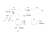
According to an aspect of the present invention, provide a kind of Method and circuits can confirm the direction of rotation of motor.Propose in " practical little computing system of brushless single phase direct current machine (A practicalmicrocomputer System for Single-Phase Brushless DC motor) " like Longfu Luo and Ziya Wang; Problem that monophase machine has met with so-called " dead point ": in some positions; The torque of motor is 0, will cause being difficult to sometimes starting like this.In order to address this problem, the pole shoe of stator ferromagnetic material can prejudicially or be formed asymmetrically (referring to instance among Fig. 1).Like what in US2006/0197478A1, propose, use tapered air gap (referring to Fig. 2), ladder tooth (referring to Fig. 3), asymmetric tooth (referring to Fig. 4) or jagged tooth (referring to Fig. 5) can obtain identical result.One side of the present invention is based on a kind of realization; Be that the shape of pole shoe is reflected in the BEMF waveform of responding in the stator winding during rotor permanent magnet is rotated on the stator; And the final waveform of BEMF can be used for confirming the electric current switching-over should be accomplished in direction of rotation and the definite stator winding of rotor moment (just, in the stator winding sense of current must the reformed moment) constantly.The BEMF waveform is assumed to sine curve (referring to Fig. 6) usually or has flat-top trapezoidal (referring to Fig. 7), departs from these shapes and has been considered to interference, and this interference must be by compensation to guarantee that motor is by control fully.
For example at US6; 577, among the 085B2, if should be noted that when magneto shows mechanical symmetry and rotor incomplete same of magnetic asymmetry or magnetic distortion or stator; Even spinner velocity is stable, this moment is unstable from the electric position of the rotor that the zero crossing of back-EMF is derived.US6,577,085B2 has proposed a solution and has compensated the asymmetric of magnetic and machinery.
One neither sine curve neither have the instance of trapezoidal BEMF waveform of flat-top shown in Fig. 8 and Fig. 9, and it is to be measured based on a general brushless single phase direct current machine with tapered air gap by the applicant.Fig. 8 and Fig. 9 have provided the function (with substantially invariable rotating speed) of BEMF signal as rotor angle location.As desired, the BEMF signal has trapezoidal shape but does not put down, and trapezoidal top has one non-0 deflection, and this has reflected that air gap is the fact of taper.The waveform of Fig. 8 and Fig. 9 is corresponding to rotor reverse rotation each other.Under different operating conditions, carried out after the research and experiment to dissimilar motors; The inventor has drawn a conclusion, and promptly the deflection of the top BC (perhaps bottom B ' C ') through the trapezoidal ABCD of monitoring (DB ' C ' D ') can be distinguished two direction of rotation (referring to Figure 10 A and Figure 10 B) of rotor when rotor rotates.As known in the art, US6 for example, 577,085B2, any brshless DC motor can, accidental or is not accidental, demonstrate asymmetric incomplete same with rotor of asymmetric or magnetic distortion of the magnetic of stator or machinery.This is not subject to the brshless DC motor (the particularly painstakingly eccentric or asymmetric pole shoe on the stator) with eccentric or asymmetric magnetic circuit painstakingly, but also is applicable to accidental appear eccentric or asymmetric motor.For the brushless single phase direct current machine is clearly discussed, the present invention also will some advantages wherein be applied to and on stator, have had two mutually or in the more heterogeneous brshless DC motor.
Motor comprises a stator and a rotor, one or more groups winding; And present asymmetric and/or eccentric (the for example asymmetric or distortion of permanent magnet rotor accidental or that have a mind to; Mechanical asymmetric between stator or the stator and the rotor of distortion; Or the like), this has influenced the variation of back electromotive force of function of the angle position of the conduct of induction in the said winding rotor relevant with stator.Motor can be the brushless single phase direct current machine with tapered air gap shown in Figure 11.Stator winding (111) (112) coils around pole shoe (113) (114).Rotor (115) comprises a permanent magnet.The position, angle of rotor (115) is with respect to the angle θ (118) between the North-South Axis (119) of fixing axis of reference (117) of stator (116) and magnets of stator.Select axis of reference (117) thus when the magnetic field of the North-South Axis of rotor permanent magnet and stator winding generation punctual θ is equaled 0 (the perhaps integral multiple of π).As illustrated in fig. 11, the air gap between rotor (115) and pole shoe (113) and (114) is taper.Tapered air gap can be that what to have a mind to also can be accidental.Tapered air gap has produced asymmetric in the distribution of induction field wire and/or magnetic field local amplitude, and it helps to solve " dead point " problem that beginning is briefly mentioned.The asymmetric of BEMF signal amplitude that is for example produced by tapered air gap is to be provided by following mathematical expression: the BEMF signal can be considered to asymmetric, if the amplitude of BEMF signal is asymmetric (even under situation of invariablenes turning speed) about the relative axis theta of graph of function shape=k* π (wherein k is an integer) of position, the angle θ of rotor.For example, Figure 10 A amplitude that can find out the BEMF signal is asymmetric about the graph of function shape of the position, angle of rotor about axis theta=π.On the other hand, if section BC is parallel with axis Theta (θ just) with B ' C ', figure will be symmetrical about axis theta=π.
Here asymmetric misalignment of perhaps having a mind to by the for example chance of asymmetric, relevant rotor chance or that have a mind to of asymmetric magnetic design, mechanical organ (rotor or stator, for example tapered air gap) of discussing or the like with stator. due to.This method comprises to back-emf signal or as the measurement function of back-emf signal and that reflect said asymmetric and/or eccentric any other signal of telecommunication.
The characteristic of this method further is to detect or derive deflection at the amplitude of one or more moment signals to confirm the direction of rotation of motor.The characteristic of this method further be the period first constantly the deflection of deflection and the amplitude of second moment signal of period of the amplitude of signal compare.The characteristic of this method further be the period first constantly the mean value of mean value and the deflection of second moment signal amplitude of period of the deflection of signal compare.
The characteristic of this method further be first and second of the period constantly be the amplitude of signal when maximum or peak swing near.Especially, first of the period is before the signal peak swing constantly, and second of the period is after said peak swing constantly.Be used for confirming that the signal of direction of rotation can be the function of back electromotive force and the variation that can reflect or follow back electromotive force.For example, signal can be the output of the adjuster of Control current amplitude in the motor.Especially, signal is the duty factor of pwm modulator.
Though this method is applicable to dissimilar motors, it is favourable having the motor that has permanent magnet on stator winding and the rotor for use, for example brshless DC motor.
Description of drawings
Fig. 1 is brushless single phase DC motor stator and the eccentric instance of rotor elements.
Fig. 2 is brushless single phase DC motor stator and the asymmetric instance of rotor elements.
Fig. 3 is brushless single phase DC motor stator and the asymmetric instance of rotor elements.
Fig. 4 is brushless single phase DC motor stator and the asymmetric instance of rotor elements.
Fig. 5 is brushless single phase DC motor stator and the asymmetric instance of rotor elements.
Fig. 6 is variation-the have trapezoidal shape of flat-top of stator winding BEMF voltage time function in the permanent magnet direct current machine.
Fig. 7 is variation-the have sine curve profile of stator winding BEMF voltage time function in the permanent magnet direct current machine.
Fig. 8 is the back electromotive force of in brushless single phase DC motor stator winding, responding to, and this brushless single phase direct current machine has the tapered air gap in the first direction rotation.
Fig. 9 is the back electromotive force of in brushless single phase DC motor stator winding, responding to, and this brushless single phase direct current machine has in the tapered air gap of rotating in the opposite direction with first party.
Figure 10 A is the desirable back electromotive force of in brushless single phase DC motor stator winding, responding to, and this brushless single phase direct current machine has the tapered air gap in the first direction rotation.
Figure 10 B is the desirable back electromotive force of in brushless single phase DC motor stator winding, responding to, and this brushless single phase direct current machine has in the tapered air gap of rotating in the opposite direction with first party.
Figure 11 is the brushless single phase direct current machine with tapered air gap and rotor angle location.
Figure 12 is sense of current and the H shape bridge of amplitude and the instance of feedback loop in the control motor.
Figure 13 is first structure of H shape bridge.
Figure 14 is second structure of H shape bridge.
Figure 15 is the transistorized control signal of control H shape bridge when PWM is used for controlling the stator winding current amplitude.
Figure 16 is the equivalent model of brushless single phase direct current machine when PWM is used for controlling the stator winding current amplitude.
Figure 17 is the variation of electric current time function in the stator winding, the duty factor sum counter output of pwm signal.
Figure 18 is the instance of adjuster.
Figure 19 is the development of electric current in the winding, and BEMF signal and duty factor are about the function of the position, angle of rotor.
Figure 20 is based on the instance that duty factor is confirmed switching-over filter constantly.
Figure 21 is the development when rotor duty factor and BEMF signal when first direction rotates.
Figure 22 is the development when rotor duty factor and BEMF signal when second direction is rotated.
Figure 23 is based on duty factor and confirms momental practical circuit.
Embodiment
Hereinafter, initial BEMF refers to back electromotive force.Anti-emf or the BEMF signal relevant with BEMF all are used in reference to back-emf signal.Agreement below when description on off state especially transistor switch, using: transistor (switch) will be considered to close (similarly being normal mechanical switch) when it allows electric current to flow through.In other words, its conducting when transistor switch cuts out.Transistor (switch) is so be switched on.Transistor (switch) is not considered to break off when it does not allow electric current to flow through.In other words, its not conducting when transistor switch breaks off.Transistor (switch) is so be considered to break off.
Drive permanent magnetic brushless and need know BEMF signal (and/or characteristic of back-emf signal) usually, especially the moment (so-called BEMF zero crossing) of elimination of BEMF signal and reindexing.Explanation below can providing from the instance that the signal of control motor is derived BEMF signal (and/or characteristic of back-emf signal) through how, zero crossing is predicted/to be confirmed to following explanation how based on the signal of control motor.And appear as above-mentioned when asymmetric when the BEMF signal, the direction of motor rotation can be confirmed by same signal.
In first embodiment, sense of current is through full H bridge control shown in figure 12 in the brushless single phase DC motor stator winding.The H bridge comprises that four are connected to power supply V with stator winding (connected with resistor 126 simulate by coil 125)
Bat(120) switch.Especially these switches can be mosfet transistor switch M1 (121), M2 (122), M3 (123) and M4 (124).Transistor switch is by the signal TL (upper left) on the grid that is applied to M1, M2, M3 and M4 respectively, TR (upper right), BL (left side down), BR (bottom right) control.Transistor switch relies on the signal (high H or low L) that is applied on its grid or opens or close.For example, M1 and M4 can be closed, and M2 and M3 break off.In that event, current i
wWith first direction in stator winding mobile (referring to Figure 13).In order to make current i
wOppositely, M1 and M4 can break off, and M2 and M3 closed (referring to Figure 14).In so-called slow decay structure, electric current is decay to zero through for example breaking off M1 and M2 and closed M3 and M4.In the so-called quick first decay structure, configuration H bridge is that (just, current amplitude will be than in slow decay structure, reaching 0 quickly in order to make electric current be in rightabout; If use the long enough time, the sense of current will be reverse, and its amplitude can increase); For example, transistor M1 (121) and M4 (124) if electric current is flowed through, thereby the electric current that obtains in the stator winding decays fast; Transistor M1 (121) and M4 (124) break off, and transistor M2 (122) and M3 (123) closure.
Current amplitude is through the readout resistor R between the source electrode that is connected benchmark ground and transistor switch M3 (123) and M4 (124)
Sense(127) measure.Comparator (128) relatively strides across the pressure drop and the reference value i of readout resistor (127)
SetTo confirm current i in the stator winding
wAmplitude less than or greater than set-point i
SetWhether.
For Control current i
wAmplitude and with i
wAmplitude (approaching as far as possible) near set-point i
Set, adjuster (129) uses the output of comparator (128) to generate control signal TL, TR, BL, BR.We mention, and come to give the control loop, feedback control loop or the feedback loop that are similar to the circuit name of representing among Figure 12 be indiscriminate: measure electric current I through using readout resistor (127)
wTo guarantee feedback, the electric current that records is then through using comparator (128) and set-point value I
SetRelatively (usually, between the value that assessment records and the set-point value different), the result is used as the input of adjuster (129), and this adjuster is confirmed one or more control signals (TL, TR, BL, BR) that are applied to exciter (H bridge).Pulse-width modulation (PWM) can be used to control the current i in the stator winding
wAmplitude.In pulse-width modulation, can not continuously and just apply supply voltage Vbat (120) in a bit of time.As a result, taken place to have experienced average activation voltage such as stator winding, this voltage is the sub-fraction of supply voltage Vbat (120).In pulse-width modulation; Be not with continuous high signal for example TL be applied to the grid of transistor M1 (121) and the grid that BR is applied to transistor M4 (124) (M2 (122) and M3 (123) disconnection simultaneously; Just signal TR and BL are low); Transistor for example M4 (124) remains closed, but transistor for example M1 (121) be switched on and cut off (referring to Figure 15).
For the Control current amplitude, transistor M4 (124) remains closed and transistor M1 (121) selectively connects and cuts off when electric current flows with another direction, and M2 (122) and M3 (123) disconnection.
When pulse-width modulation is used for controlling the stator winding current amplitude; The equivalent electric circuit of H bridge and motor is shown in Figure 16: for example switch (161) can be transistor M1 (element 121 among Figure 12) when electric current must flow with first direction; Or switch (161) can be transistor M2 (element 122 among Figure 12) (referring to Figure 12) when electric current must flow with second direction, back electromotive force or bemf that voltage source (162) expression is responded in stator winding through the permanent magnet of epitrochanterian rotation.Stator winding can pass through inductor (165) and resistors in series (166) simulation.Electric current circulated in stator winding when fly-wheel diode (163) allowed switch (161) to break off.Fly-wheel diode can be painstakingly do or can be the for example parasitic diode of M3 or M4 of transistor switch.For example, when switch 161 was transistor M1, fly-wheel diode 163 can be the parasitic diode related with transistor M3 so.When switch 161 was transistor M2, fly-wheel diode 163 can be the parasitic diode related with transistor M4 so.Especially, if transistor M3 and M4 are n type MOS transistor (wherein, the bulk effect electrode are frequent, but not always, with the source electric pole short circuit), in that event, drain electrode-bulk-effect diode of M3 or M4 can be used as fly-wheel diode in some cases.Voltage source 160 and switch 161, inductor 165 and resistor 166 polyphones.Notice that fly-wheel diode (163) is not strictly essential.In fact can use effective diode to proceed.The effect of the fly-wheel diode of similar diode (163) allows electric current to flow through coil (165) exactly when switch (161) breaks off.In the H bridge, the role of fly-wheel diode can one of them be born by transistor M1, M2, M3 or M4, and cost is the complexity that has increased a little like the operation of PWM pattern how H bridge.For example, suppose all to be in closure state, in order to allow/impel electric current I like the transistor M1 and the M4 that in Figure 13 and Figure 15, see
wDirection given flows through.In the PWM pattern, like what below will be described in more detail, when transistor M4 remains closed, disconnection that transistor M1 is repeated and closure.When transistor M1 breaks off, there is not the electric current can be from V
Bat(120) stator winding (125) of flowing through.Fly-wheel diode and stator winding (just element 15,16) parallel connection, when transistor M1 breaks off, electric current continue to flow through stator winding and fly-wheel diode.If there is not fly-wheel diode, can closed transistor switch M3 when transistor switch M1 breaks off, thus electric current I
wLoop 126,125-M4-readout resistor 17-GND-M4-16 will flow through.For fear of from V
BatTo the short circuit of GND, closure that must delay crystal pipe M3 (perhaps at least, is broken off fully), and before closed transistor M1, must be broken off transistor M3 fully up to transistor M1.
In pulse-width modulation, the control signal of disconnection or close switch 161 (when using transistor M1 (121), perhaps when using transistor M2 (122), being TR as TL) can be seen in Figure 15 (referring to the variation of TL as the function of time) or Figure 17 (referring to the variation of pwm signal as the function of time).Can see that control signal changes between low level (L) and high level (H).Low level and high level are so so that they can closedly perhaps break off the switch that it is suitable for.Time is divided into and equals length T
PWMThe interval.The PWM frequency f
PWMBe restricted to interval T
PWMInverse, f just
PWM=1/T
PWMThe pwm signal that in first preferred embodiment, also is called as control signal (for example, TL or TR) is at each time interval T
PWMSub-fraction in remain height.This sub-fraction can be from an interval to another interval variation.
Current i in the stator winding
wCan be according to following equality along with the time changes:
When switch 161 closures,
Vbat=-L
wDi
w/ dt+R
wi
w+ V (BEMF)+R
Sensei
w(equality 1);
And when switch 161 breaks off,
0=-L
wDi
w/ dt+R
wi
w+ V (BEMF)+R
Sensei
w(equality 2).
According to equality 1, under the situation that all other all equate at all, it is long more that switch 161 remains closed the time, current i
wIt is just big more that amplitude increases.Similarly, according to equality 2, under the situation that all other all equate at all, switch 161 keeps the time of disconnection long more, current i
wIt is many more that amplitude reduces.In pulse-width modulation, switch 161 is closed as the function of the output of comparator (128) or breaks off.
Control signal is generated by adjuster 129 (especially, like that in first embodiment, is considered, pwm modulator), and must satisfy some condition.For example, in order to avoid audio frequency, the PWM frequency f
PWMThe selecteed audio frequency that is higher than.Duty factor DC will be restricted to cycle T
PWMSub-fraction, in cycle T
PWM(entirely) supply voltage V
BatBe applied on the stator winding.For fear of the sub-harmonic wave that produces the pwm signal in the audio range, got rid of 0 and 100% duty factor.Especially, can adopt following mode to avoid 0% and 100% duty factor (referring to Figure 17): pwm signal is at PWM cycle (D at least
Min* T
PWM) be high when beginning, as long as the electric current in the coil does not also reach like the indicated reference value I of the output of comparator 128
Set, pwm signal just remains height always.Do not consider the current i in the stator
w, in time D
Max* T
PWM(* is the operator of multiplication) afterwards, the output of PWM is at D
MaxT
PWMAnd the part in the PWM cycle between the end in this PWM cycle always is set as 0.D
MaxCommon value is 0.75.D
MinValue be generally 0.05.Pwm signal can sense of current as required be applied to the grid of transistor M1 (121) or transistor M2 (122).
The electric current that needs in the stator winding is high more, and the average activation voltage that experiences in the stator winding is just necessarily high more, and duty factor is also necessarily high more.Constant for current amplitude in the maintenance stator winding when the BEMF signal amplitude increases (under the situation that all other all equate at all), duty factor must correspondingly increase: in fact, the bemf signal produces and the supply voltage reverse effect.For current constant in (under the situation that all other all equate at all) maintenance stator winding when the BEMF signal amplitude reduces, duty factor must correspondingly reduce.Therefore, the variation of duty factor DC " mirror image " is in the variation of BEMF signal amplitude.Therefore, in the circuit of similar Figure 12, can from the duty factor of pwm signal, extract about the information of BEMF signal.
A concrete enforcement of adjuster 129 can be seen in Figure 18.The output OUTA of comparator 128 be used as D flip-flop 181 reset signal (just, when signal OUTA corresponding to being equivalent to I
Set<I
wLogic ' 0 ' time, the output Q of the trigger logic state 0 ' that is reset).Pulse signal " PWM begins " by the ad-hoc signal generator produces confirms that the beginning in PWM cycle and the D of slave flipflop 181 are input to Q output logic with shift ' 1 ' signal.Identical " PWM begins " signal counter 183 (just, counter 183 is set and is output as a preset value) that resets.For the sake of clarity, unless otherwise indicated herein, we will suppose that counter begins hour counter in each PWM cycle and is reset to 0.For example counter 183 can be a binary counter, and its output is by effective serial or the parallel N that constitutes
CounterThe position is formed.The output of counter is 0 and 2
NcounterChange between-1.When in logic ' 1 ', the signal triggering counter 183 in the Q output, its counting is the frequency f than PWM by frequency that signal generator 184 produces
PWMHigher f
CLCKClock signal C LCK.Usually select clock frequency so that the PWM cycle T
PWM(substantially) equal the clock signal period T of integral multiple NB
CLCK=1/f
CLCK, T just
PWM=NB*T
CLCKPWM cycle T for example
PWMCan be 128 CLCK Cycle Lengths.As long as Q is high, counter 183 is by clock signal C LCK increment.Q is a pwm signal, as long as as long as the output OUTA of comparator 128 is in logic ' 1 ', just the current i in the stator winding
wBe lower than reference value i
Set, Q just remains height so.Based on above-mentioned; At the end in PWM cycle, the quantity in the CLCK cycle that the output of counter equals to be calculated by counter 183 is at this PWM during pwm signal is high in the cycle; Just the output of the terminal counter in PWM cycle and duty factor proportional (+/-1/2LSB; Just, NB*DC, wherein LSB representes least significant bit and the minimum possibility increment of exporting corresponding to counter).As foregoing, if want to avoid 0% and 100% duty factor, for example can be at least one clock cycle and maximum D
MAX* the NB clock cycle remains height with pwm signal.This is to realize easily through known way combinational logic signals a large amount of in the prior art in logical circuit.Circuit among Figure 18 can also comprise latch cicuit 185, in case the output Q of trigger 181 reverts to 0, it can latch the content of counter, and counter is incited somebody to action no longer increment.
Digital circuit, the piece 182 among Figure 18 begins and I based on signal Q, CLCK, PWM
SetThe direction (signal Dir) that requires is confirmed signal BL, BR, TL and TR.For example, the electric current of first direction if desired, piece 182 will guide the control utmost point TR of Q to transistor M2 (122), BL will be set for high (closed transistor M3) and BR is set and TL is low (disconnection transistor M1 and M4).Do not have fly-wheel diode, the signal BR that piece 182 will be provided with as the function of signal TR state flows through stator winding for high perhaps low (referring to top) to allow electric current, avoids the short circuit from Vbat to GND simultaneously.
The electric current of second direction if desired, piece 182 will guide the control utmost point TL of Q to transistor M1 (121), be provided with BR for high (closed transistor M4) with BL is set and TR is low (disconnection transistor M2 and M3).Do not have fly-wheel diode, the signal BL that piece 182 will be provided with as the function of signal TL is that high or low (referring to top) flow through stator winding to allow electric current, avoids the short circuit from Vbat to GND simultaneously.
Duty factor DC and in Figure 19, can see as the instance that the BEMF signal of the function of rotor-position changes.In Figure 19, we can use the trapezoidal signal ABCD simulation with non-flat-top not have the BEMF of limited field.As previously discussed, for given I
SetUnder all other all equate at all situation; When the amplitude of BEMF signal increases; The duty factor DC of the pwm signal of electric current also increases in the control motor, and when the amplitude of BEMF signal reduced, the duty factor DC of the pwm signal of electric current also reduced in the control motor.The amplitude that duty factor DC reaches peaked while BEMF signal also reaches maximum.Based on the known characteristic of BEMF signal, the amplitude of BEMF signal (sharply) reduces, thereby also (sharply) reduction of duty factor DC has indicated rotor-position very near reversal point (the BEMF signal is near zero crossing).Therefore, for example (the some C among Figure 19) or duty factor reach after the maximum soon when duty factor reaches maximum, have taked to make the decision of current reversal.In Figure 19, the first possibility direction of electric current is corresponding on the θ axle, representing I
wBe the part of the graph of function shape of θ, just corresponding to electric current on the occasion of second of, electric current maybe direction corresponding to the figure of the part below the θ axle, just it is corresponding to the negative value of electric current.When set point by the negative value (I among Figure 19
SetWhen<0) representing, it must be understood that the reference signal I on the input that is applied to comparator 128
SetCan not change; But sense of current is second in the stator winding: the amplitude of electric current is still detected by readout resistor 127; Readout resistor can be used to measure current amplitude and need not consider its direction, and the switch M1 to M4 of H bridge is configured (just breaking off or closure) so that electric current flows with selecteed direction.The switch of H bridge is reconfigured so that behind the current reversal in the stator winding, owing to the self-induction of stator coil, electric current I
wDirection will be not reindexing: I at once
wAmplitude will at first reduce to reach 0 I up to it
wSymbol will change (zero passage), its amplitude is with this increase again.From I
w=I
SetTo I
w=-I
SetConversion in, I
wAmplitude will become less than I
Set(| I
w|<I
Set), pwm modulator 129 is through increasing duty factor DC reinstatement.Rely on set point I
Set, motor characteristic and its rotary speed, in Figure 19, represent from I
w=I
SetTo I
w=-I
SetMajor part conversion or whole transfer process in, duty factor can be forced to maximum D
Max
Figure 20 provides the principle schematic that can be used for confirming switching-over logical circuit 200 constantly whether (no matter BEMF signal symmetry, the BEMF signal can be had flat-top or have the trapezoidal of non-flat-top by simulation).Register 201 is stored in t constantly
0With moment t (t
0<t) between the peak HDC of detected duty factor DC.The content 203 of comparator 205 comparand registers 201 and by DC counter (with latching) 202 detected electric current DC 204, if electric current DC 204 is higher than the content 203 of register 201, the content update of register 201 is electric current DC 204.
In order to confirm when to change electric current I in the stator
wDirection, the difference of the content 203 of electric current DC 204 and register 201 constantly compares by estimation and through the some of comparator 207 with the content 203 of register 201.In case the difference between the content 203 of electric current DC 204 and register 201 is higher than the [t at the interval
0, t] in the peaked given percentage of the DC that reaches, the direction of stator current just is changed, perhaps in other words, if (HDC-electric current DC)>HDC/N, the direction of stator current just is changed so.The indicator current direction must reformed signal 208 be available in the output of comparator 207.For binary representation and the realization of simplifying division are provided, N will be preferably 2 integral multiple.This does not get rid of generally, and N is the value of any other type.N can be considered to sensitivity coefficient, and it confirms that the switching-over of the electric current in the triggering stator winding needs the duty factor of much variations.Through changing the value of N, can change the moment of electric current switching-over in the stator winding and optimize electric current switching-over as the function of the characteristic of motor.
Moment that the sense of current of the content HDC of register 201 in stator winding changes for example is initialized as 0 by (again).Like what in Figure 19, see, when the H bridge is reconfigured when impelling electric current in the stator winding to change direction (in switching-over constantly just), the common overshoot of control loop, duty factor will reach its maximum.In order to prevent that overshoot is interpreted as the maximum of leading switching-over BEMF signal constantly, needs some filtrations.For example; (1) exceeded from a given BEMF profile (gradient; Peak swing; Or the like) variation of two the continuous duty factors of PWM between the cycle changing of the maximum of expection can be out in the cold (just; The content HDC of register 201 is not updated) or be used for resetting register 201 for for example 0 (at Figure 19, register 201 can through occur in duty factor around the D reduce suddenly be reset) perhaps (2) need only and also do not reach the minimum value of DC in the cycle, the content HDC of register 201 just is reset.In fact, can in Figure 19, see, along with the increase of the amplitude of BEMF and increase with keep current amplitude in the stator winding constant before, duty factor will begin to reduce from its overshoot.These filter criterias can adopt the mode of a large amount of user mode machines well known in the art, microcontroller, microprocessor or the like to realize.
When the BEMF signal is asymmetric, the register 201 last moment t that reset
0Change the moment t of (output by the for example circuit shown in Figure 20 is confirmed) with the sense of current
1Between the duty factor measured can be used for confirming the direction of the rotation of amount of exercise (for example, angular displacement, angular speed, angular acceleration) and motor in a different manner.
At first consider to confirm first method of motor direction of rotation based on the analysis of the signal of representing by Figure 21 and Figure 22.Duty factor DC is fed back to first filter 231 of carrying out above-mentioned filtration.Begin (for example determined by last reset signal) from t0, as long as duty factor DC does not also reach its maximum, counter 232 all adds 1 in each PWM cycle.In case duty factor DC is at moment t
Max(t
0<t
Max<t) reaching its maximum, counter 232 subtracts 1 in each PWM cycle.Constantly t can be determined by that kind of top explanation, for example based on the output of circuit among Figure 20.At moment t, the content of counter is latched, if the latch content of counter 232 just means that for just the PWM amount of cycles of duty factor DC increase is more than the PWM amount of cycles that duty factor DC reduces.This is interpreted as rotor and rotates at first direction corresponding to the BEMF signal, like what in Figure 21, see.If opposite, the content of counter 232 is found to be negative, means that the PWM amount of cycles of duty factor DC increase is lacked than the PWM amount of cycles that duty factor DC reduces.This is interpreted as rotor and rotates in second direction corresponding to the BEMF signal, like what in Figure 22, see.
Consider now based on realizing that with the circuit of calcspar among Figure 23 the analysis of the signal shown in Figure 21 and Figure 22 confirms second method of the direction that motor rotates.
At first filter duty factor DC according to filter criteria previously discussed through filter 240.For example filter can be as commonly known in the art based on schematic diagram among Figure 20 and VHDL combination.Clock 241 allows Measuring Time/time interval.Filter 240 confirms when seeking a maximum, when to begin to measure duty factor.Filter 240 is confirmed t constantly
0And the maximum duty factor between the t.As DCt
Max, DCt
0With the maximum duty factor of DCt, the duty factor of the duty factor of t0 and moment t is confirmed by filter 240 constantly.These three values and the corresponding moment t0 of difference that measures by clock 241, t
MaxDeposited in register 242 together with t.
The absolute value of first average rate that AARI1 increases as duty factor DC is at moment t0 and t constantly
MaxBetween by being calculated.AARI1 is similar to by arithmetic unit 243 according to following equality 3 and draws:
AARI1=| (DCt
Max-DCt
0)/(t
Max-t
0) | equality 3
The absolute value of second average rate that AARI1 increases as duty factor DC is at moment t0 and t constantly
MaxBetween by being calculated.AARI2 is similar to by arithmetic unit 243 according to following equality 4 and draws:
AARI2=| (DCt
Max-DCt)/(t
Max-t) | equality 4
In order to simplify the calculating of AARI1 and AARI2, equality 3 and 4 denominator can be by (NMAX-N0) and (NMAX-NEND) are replaced, and wherein N0, NMAX and NEND are respectively the PWM cycles through t constantly
0, t
MaxQuantity with moment t.Usually, N0 equals 0.Through calculating respectively at t0 and t
Max, the signal generator 184 of Figure 18 produces between t0 and the t PWM commencing signal quantity, can obtain NMAX and NEND at an easy rate.For example the quantity in PWM cycle can be used the quantity acquisition that a lot of known modes pass through to calculate the PWM commencing signal in the prior art.Filter and clock can be the parts of all-purpose computer 244 μ that see among Figure 23 (microcontroller, microprocessor, microcomputer, or the like).
If AARI1<AARI2 can be interpreted as rotor correspondence as BEMF signal seen in fig. 21 and rotate at first direction.
If AARI1>AARI2 can be interpreted as rotor correspondence as BEMF signal seen in fig. 22 and rotate in second direction.
Attention amount AARI1 and AARI2 can directly be calculated through the BEMF signal; Just as its measured or estimation through special-purpose transducer; For example stride across the voltage drop of coil pickoff; When one of bi-pole stepper motor was used for confirming the position of stepping motor rotor as transducer mutually, described coil pickoff can be the winding of this phase of bi-pole stepper motor.When the BEMF signal is asymmetric, be proposed to be used in the method for confirming the motor direction of rotation, be not limited to single-phase stepper motor with the operation of PWM pattern.
The clocking information that provides based on the analysis of duty cycle signal with by clock can compute classes like the amount of exercise of angular displacement and angular velocity omega.Start from the first maximum duty factor by filter 240 detections, the content NbMax of register is by increment and reference time t
RefBe stored.No matter when need, angular displacement can be estimated based on the relation between value NbMax and Bemf signal shape and the rotor angle location.For example, when the bemf signal changes as shown in Figure 10 A, from t
RefThe angular displacement of beginning is near (NbMax-1) * ∏.Angular velocity omega can be near (NbMax-1) * ∏/(t
NbMax-t
Ref).