CN101309727B - Respiratory mask - Google Patents
Respiratory mask Download PDFInfo
- Publication number
- CN101309727B CN101309727B CN2006800426830A CN200680042683A CN101309727B CN 101309727 B CN101309727 B CN 101309727B CN 2006800426830 A CN2006800426830 A CN 2006800426830A CN 200680042683 A CN200680042683 A CN 200680042683A CN 101309727 B CN101309727 B CN 101309727B
- Authority
- CN
- China
- Prior art keywords
- capsule
- substrate
- breathing mask
- holding element
- forehead
- Prior art date
- Legal status (The legal status is an assumption and is not a legal conclusion. Google has not performed a legal analysis and makes no representation as to the accuracy of the status listed.)
- Expired - Fee Related
Links
Images


Classifications
-
- A—HUMAN NECESSITIES
- A61—MEDICAL OR VETERINARY SCIENCE; HYGIENE
- A61M—DEVICES FOR INTRODUCING MEDIA INTO, OR ONTO, THE BODY; DEVICES FOR TRANSDUCING BODY MEDIA OR FOR TAKING MEDIA FROM THE BODY; DEVICES FOR PRODUCING OR ENDING SLEEP OR STUPOR
- A61M16/00—Devices for influencing the respiratory system of patients by gas treatment, e.g. mouth-to-mouth respiration; Tracheal tubes
- A61M16/06—Respiratory or anaesthetic masks
- A61M16/0605—Means for improving the adaptation of the mask to the patient
- A61M16/0616—Means for improving the adaptation of the mask to the patient with face sealing means comprising a flap or membrane projecting inwards, such that sealing increases with increasing inhalation gas pressure
- A61M16/0622—Means for improving the adaptation of the mask to the patient with face sealing means comprising a flap or membrane projecting inwards, such that sealing increases with increasing inhalation gas pressure having an underlying cushion
-
- A—HUMAN NECESSITIES
- A61—MEDICAL OR VETERINARY SCIENCE; HYGIENE
- A61M—DEVICES FOR INTRODUCING MEDIA INTO, OR ONTO, THE BODY; DEVICES FOR TRANSDUCING BODY MEDIA OR FOR TAKING MEDIA FROM THE BODY; DEVICES FOR PRODUCING OR ENDING SLEEP OR STUPOR
- A61M16/00—Devices for influencing the respiratory system of patients by gas treatment, e.g. mouth-to-mouth respiration; Tracheal tubes
- A61M16/06—Respiratory or anaesthetic masks
- A61M16/0605—Means for improving the adaptation of the mask to the patient
- A61M16/0633—Means for improving the adaptation of the mask to the patient with forehead support
-
- A—HUMAN NECESSITIES
- A61—MEDICAL OR VETERINARY SCIENCE; HYGIENE
- A61M—DEVICES FOR INTRODUCING MEDIA INTO, OR ONTO, THE BODY; DEVICES FOR TRANSDUCING BODY MEDIA OR FOR TAKING MEDIA FROM THE BODY; DEVICES FOR PRODUCING OR ENDING SLEEP OR STUPOR
- A61M16/00—Devices for influencing the respiratory system of patients by gas treatment, e.g. mouth-to-mouth respiration; Tracheal tubes
- A61M16/08—Bellows; Connecting tubes ; Water traps; Patient circuits
- A61M16/0816—Joints or connectors
- A61M16/0825—Joints or connectors with ball-sockets
Abstract
A respiratory mask (10, 10a, 10b, 10c) generally including a base plate (14, 14a, 14b, 14c) adapted for connection to a gas source and a bladder (52, 52a, 52b, 52c) secured to the base plate (14, 14a, 14b, 14c) to form a generally fluid tight seal with the base plate (14, 14a, 14b, 14c), and defining at least one internal chamber (74, 74a, 74b, 74c) with the base plate (14, 14a, 14b, 14c) for receiving a fluidizing medium to fill the bladder (52, 52a, 52b, 52c) and form a resilient cushion.
Description
Priority application
According to 35U.S.C. § 119 (e) clause, the application requires the 60/736th, No. 709 U.S. Provisional Application No. of application on November 15th, 2005, and wherein the content of this application file is here introduced through reference.
Technical field
The present invention puts it briefly and relates to flow delivery systems, and more particularly, relates to and utilize breathing mask to flow to gas patient's flow delivery systems.
Background technology
Flow delivery systems is used for being transported to curee's air flue to gas stream.Flow delivery systems instance at medical domain comprises ventilator or the respirator that replaces or assist patient respiration; And also comprise pressure support system; Wherein this pressure support system is fed to patient airway to gas stream with elevated pressure; With treatment medical conditions, for example obstructive sleep apnea (OSA).Yet pressure support system comprises and do not limited continuously positive airway pressure (CPAP) apparatus and transformation apparatus, wherein should be continuously just air flue press tool be transported to a plurality of respiratory cycles of patient airway to pressure power; And the gas flowing pressure that flows to patient in the transformation apparatus changes.
The transformation apparatus comprises the automatic titrator tool, and wherein this apparatus can change pressure of foundation or the pressure distribution that flows to patient according to patient's monitor state.Other transformation apparatus changes the pressure of gas stream during the respiratory cycle.These apparatuses comprise as follows: by the Respironics manufactured of Pennsylvania, America Pittsburgh and the proportional auxiliary ventilation (PAV that sells
 ) device, proportional positive airway pressure (PPAP) device, C-Flex
TMDevice, two-Flex
TMDevice and BiPAP
) device, proportional positive airway pressure (PPAP) device, C-Flex
TMDevice, two-Flex
TMDevice and BiPAP
 Device.BiPAP
device is two horizontal pressure force back-up systems; The pressure that wherein is fed to patient is along with the patient's breath cycle changes, so that the conveying of the intake period except that between expiration elevated pressures.
Device.BiPAP
device is two horizontal pressure force back-up systems; The pressure that wherein is fed to patient is along with the patient's breath cycle changes, so that the conveying of the intake period except that between expiration elevated pressures.
Typical flow delivery systems comprises the pressure that produces the gas stream that flows to patient/flow generation system and the system of this gas flow communication to patient.The latter system usually comprises having the flexible pipe that is connected to pressure/flow to produce an end of apparatus and is connected to the second end of patient airway via patient interface.This flexible pipe is also referred to as the patient circuit, during system works, is carrying the gas stream from the pressure generator tool.The second end that the patient interface that is typically nose, oral cavity or nose/oral mask is connected to flexible pipe with from patient circuit's gas flow communication to patient airway.
It is known utilizing expansion contact rim or pullover patient interface.Usually, expand into desired pressure, and therefore can accurately coincide with wearer's face yet this rim makes air pressurized still have elasticity through use.In this mode, realized the tight contact of the expectation between face shield and wearer's face.
The expansion rim is usually taked " interior pipe " type expansion structure.This expansion rim is folding through integral membrane usually, perhaps through blow molding, perhaps through " mud " molding process.Usually, whichever technology is used for forming the expansion rim, and special method (for example bonding or welding) is that to form moulding material circumference closure at last necessary, thereby forms the inner space that isolates.Special closing apparatus (for example referring to the 3rd, 695, No. 264 United States Patent (USP)s) must be provided, thereby air remains in this inner space after rim is expanded, this has also increased the totle drilling cost of face shield simultaneously.At last, also a defective is, has to start closing device owing to rim at first must expand, and the face shield that therefore forms always is not in stand-by state.
Known in the artly be, have the breathing mask of non-pneumatic " filling " material of gel for example or liquid, be used for remaining on constant stand-by state (for example remaining on tension or elastic stage) to rim through filler at rim.Yet this type rim has and identical manufacturing defect previously discussed, wherein only omits closing device.At last, the unexpansive rim that is used for breathing mask is traditionally through the sulfurization manufacturing, and this also is relatively costly.Describe hereinafter and disclose the patent that the type of mask rim structures is described in various forms of fronts.
The 790th, No. 057 United States Patent (USP) discloses early stage suction anaesthetic mask, and wherein this face shield has inside radian roughly, is adapted to patient's bridge of the nose.The 1st, 206, No. 045 United States Patent (USP) discloses nasal inhaler, wherein have hard, airtight support shell, and this shell has " flange " processed by plastic material, between shell and patient, as sealing device.The 2nd, 313, No. 999 United States Patent (USP) discloses two shell face shields being processed by flexible rubber.The 2nd, 535, No. 938, the 2nd, 625, No. 155, the 2nd, 765, No. 788 and the 3rd, 042, No. 035 United States Patent (USP) disclose the face shield with the relative relatively hard materials that forms the mask seal flange.The disclosed downward pressure that is applied on the face shield is tended to through making relative skin and muscle response increase the sealing between wearer's face and the flange in these patents, yet has increased the uncomfortable property of wearer.The 2nd, 875, No. 757 United States Patent (USP) discloses the expansion sleeve head dummy face shield with expansion valve.
The 4th, 062, No. 357 United States Patent (USP)s disclose the face shield of the recent model with expansion rim.Disclosed face shield comprises panel and is attached to the fills with air pad rim on the panel in this patent.The 4th, 201, No. 205 United States Patent (USP) discloses the oxygen mask with flexible and transparent plastic shell, and wherein this flexible and transparent plastic shell has and is increased in the flange that seals between face shield and the wearer's face.The 4th, 347, No. 205 United States Patent (USP) discloses the expansion rim with two inner-cavity structures.The 4th, 803, No. 981 United States Patent (USP) discloses the nose inhalator that only has the hard rubber foamed material, and wherein this foamed material is used for meshing with wearer's nose.The 4th, 807, No. 617 United States Patent (USP) discloses the ventilation face shield that cooperates with the face shield with expansion rim.The expansion valve that the 4th, 913, No. 401 United States Patent (USP)s disclose with the rim that is used to expand is the valve member of representative.The 4th, 971, No. 051 United States Patent (USP) discloses the CPAP apparatus with expansion rim, and wherein this rim expands under the gas pressure that provides through air bag.
D293, No. 613 U.S.'s design patent discloses the expansion rim form face shield with the expansion valve that is positioned at nasal bridge region.D323; No. 908 U.S.'s design patents disclose the expansion rim formula face shield of the extension with the support shell on the bridge of the nose just or base portion, and this during use support shell or base portion are used to support one or more fingers of anesthesiology doctor or nurse.
The 5th, 121, No. 745 United States Patent (USP) shows expansion rim formula face shield, and this face shield is used in particular for the CPR application scenario, when not using, is foldable to slim simultaneously.
The 5th, 738, No. 094 United States Patent (USP) discloses the face shield with expansion rim, comprising the panel that has circumference rim or flange and adhere to or be fastened to the fills with air rim on the panel flange.The 6th; 408, No. 853 United States Patent (USP)s disclose to have roughly with the 5th, 738; The face shield of No. 852 disclosed similar expansion rims of United States Patent (USP); Yet also disclose a kind of like this method, promptly formed the expansion rim, thus this rim can have rim towards the increase wall thickness of flange side and towards patient-side than small walled.At last, the 6th, 834, No. 650 United States Patent (USP)s disclose face or the nose face shield with two annular chambers that form the liner rim.Each chamber is that air expands, and can pressurize continuously through ambient air source.
In view of the foregoing, need a kind of improved breathing mask, wherein mask part is made easily, is convenient to the face shield assembling thus.In addition, also need a kind of like this breathing mask, wherein this breathing mask is convenient to put on and regulate, and is comfortable for the wearer.In addition, also have special like this needs, promptly breathing mask has and presents expansion contact rim or the liner that improves sealing characteristics, expands easily and shrinks the bulbs of pressure that the while can be set up and kept expecting.
Summary of the invention
Breathing mask of the present invention generally includes the substrate that is suitable for being connected to gas source; And be fastened to this substrate to form the roughly capsule of liquid tight with substrate; Wherein this capsule limits at least one inner chamber with substrate, is used for the admitting fluid medium and fills capsule, and form elastic insert.Fluidized medium can be the gas of for example air, for example as an example the liquid or the for example other materials or any combination of gas, liquid or solid dielectric of gel of mineral oil or salting liquid.If gas medium is as the fluidized medium of capsule, then this breathing mask will comprise pneumatic dunnage.In such an embodiment, the pressure-reducing valve that is connected with inner chamber can be useful, is used to regulate the pressure of inner chamber and limiting pressure therein, usually improves breathing mask wearer's comfort properties.
Another aspect of invention relates to a kind of capsule that is used for breathing mask.This capsule comprises the main body that is made up of integral body that limits U-shaped cross-section roughly.The capsule main body has uneven wall thickness on whole roughly U-shaped cross-section.The capsule main body comprises and limits the roughly base portion and the cushion part of U-shaped cross-section.Base portion comprises relative flange, and this relative flange is suitable for being connected capsule with the substrate of breathing mask.The base portion wall thickness is greater than cushion part.The capsule main body is surrounded the forehead extension that stretches out from the breathing mask substrate.In addition, the capsule main body can comprise that at least one inner separator is to limit a plurality of inner chambers therein.
Another aspect of the present invention relates to the method for assembling breathing mask.This assemble method generally comprises: the substrate that is suitable for being connected to gas source is provided; The expandable bladder that is suitable for being connected to this substrate is provided; And be fixed to capsule on the substrate, forming roughly liquid tight, and limit at least one inner chamber with substrate with substrate; Be used for the admitting fluid medium and fill capsule, and form elastic insert.
Be fixed to step on the substrate to capsule and can comprise and utilize holding element being fixed to capsule on the substrate, thereby form liquid tight roughly with this substrate.In addition, this method can comprise through connecting holding element with mechanical means or being bonded on the substrate and being fixed to this holding element on the substrate.This capsule generally includes the main body that is made up of integral body that limits U-shaped cross-section roughly.This capsule main body can comprise and limit the roughly base portion and the cushion part of U-shaped cross-section, and can comprise the step that capsule is fixed to substrate and to be clipped at least a portion base portion between holding element and the substrate, to form liquid tight roughly with substrate.
In another embodiment, this breathing mask generally includes substrate, and wherein this substrate comprises the guide rail that limits a plurality of grooves and is engaged on the blocking device in the guide rail.This blocking device can generally include the locking main body with the relative sidepiece that is connected with second Connection Element through first Connection Element.Second Connection Element can limit central opening, and strain at least in part.This blocking device can also comprise the post element that is positioned at central opening, and this post element also has with first end of first Connection Element engagement with from central opening and stretches out and be engaged on second end in one of them groove the guide rail.In operation, when power orientation column element acted in the opposite side at least one, second Connection Element was usually in the distortion of orientation column element second extreme direction, thus from promoting second end with the groove position of engagement.
Opposite side can form finger-like and grasp the surface.In addition, the 3rd Connection Element can connect opposite side, and is defined for the space that receives frenulum with first Connection Element.Second Connection Element can comprise the strain distal portion that limits central opening.In addition, locking main body and post element can for example integrally be formed by plastic material, are perhaps for example formed by plastic material as dividing member.Second end of post element can comprise globe joint.This globe joint can comprise and is used for the tongue piece that aligns with groove.
In another embodiment, this breathing mask generally includes substrate, and wherein this substrate comprises the guide rail that limits a plurality of grooves and is engaged on the blocking device in the guide rail.This blocking device can generally include the locking main body with the relative sidepiece that is connected with second Connection Element through first Connection Element.Second Connection Element can limit central opening, and comprises the part of the strain that contacts with guide rail.This blocking device can also comprise the post element that is positioned at central opening, and the locking main body also has with first end of first Connection Element engagement with from central opening stretches out and be engaged on second end in one of them groove the guide rail.In operation; When power when affacting the locking main body with post element alignment or parallel direction; Second Connection Element further passes second end of the outstanding post element of central opening thus usually in the direction distortion towards first Connection Element, and from promoting second end with the groove position of engagement.
In this embodiment, the 3rd Connection Element can connect opposite side, and is defined for the space that receives frenulum with first Connection Element.Second Connection Element can comprise the strain distal portion that limits central opening.In addition, locking main body and post element can for example integrally be formed by plastic material, are perhaps for example formed by plastic material as dividing member.Second end of post element can comprise globe joint.This globe joint can comprise and is used for the tongue piece that aligns with groove.
After with reference to the research of accompanying drawing to following description and accessory claim book; These and other purpose of the present invention, characteristic and characteristic; And the economy of the method for operating of structurally associated element and function, unit construction and manufacturing will become more obvious; Institute's drawings attached and claims all constitute the part of this specification, and wherein in each accompanying drawing, identical Reference numeral is represented corresponding component.Yet what should be expressly understood that is that accompanying drawing only is used to illustrate and describe, and does not want as the restriction to invention.As using in specification and claims, only if outside context clearly stipulated, " one " and " being somebody's turn to do " of singulative also comprised a plurality of indicants.
Description of drawings
Fig. 1 is the front perspective view according to breathing mask oral area of the present invention-nose embodiment;
Fig. 2 is breathing mask second back perspective view among Fig. 1;
Fig. 3 is the breathing mask perspective view among Fig. 1;
Fig. 4 is the breathing mask decomposition diagram among Fig. 1;
Fig. 5 is breathing mask second decomposition diagram among Fig. 1;
Fig. 6 is for forming the rearview of the capsule of breathing mask inflated insert among Fig. 1;
Fig. 7 is the perspective view of capsule shown in Figure 6;
Fig. 8 is the substantial transverse cutaway view of breathing mask in Fig. 1 of Fig. 1 center line 8-8;
Fig. 9 is the roughly longitudinal sectional view of breathing mask in Fig. 1 of Fig. 1 center line 9-9;
Figure 10 is for along Fig. 1 center line 10-10 and second transverse sectional view roughly that shows breathing mask among Fig. 1 of supplementary features;
Figure 11 is the decomposition diagram of another embodiment of breathing mask among Fig. 1;
Figure 12 is the decomposition diagram of breathing mask among the Figure 11 that only shows face shield capsule and holding element;
Figure 13 A is perspective view and the partial sectional view that shows in the substrate of Fig. 1 breathing mask and the mechanical fixation mechanism between the holding element;
Figure 13 B is perspective view and the partial sectional view that shows the mechanical mechanism alternate embodiment;
Figure 13 C is perspective view and the partial sectional view that shows mechanical fixation mechanism alternate embodiment;
Figure 13 D is perspective view and the partial sectional view that shows mechanical fixation mechanism for implementing example;
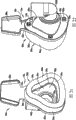
Figure 14 a is the fixedly rearview of the expansion rim of forehead pad that has that is used for the other embodiment of breathing mask;
Figure 14 b is the perspective cutaway view, along the expansion rim of Figure 14 a line 14b-14b.
Figure 15 is the decomposition diagram that shows breathing mask embodiment among Fig. 1;
Figure 16 shows to be used for being fixed to perspective view locking, Fig. 1 breathing mask part on the face shield to fixing frenulum;
The locking decomposition diagram that Figure 17 unloads from breathing mask for locking among Figure 16;
Figure 18 is the perspective view that shows a breathing mask part, and wherein breathing mask has the locking that is connected with this breathing mask shown in Figure 16;
Figure 19 is the perspective view according to the locking of another embodiment;
Figure 20 is the longitudinal sectional view of locking among Figure 19;
Figure 21 covers the perspective view of embodiment for the breathing mask nose;
Figure 22 is the perspective view of breathing mask from Figure 21 that face shield wearer contact side is observed;
Figure 23 is the perspective view of breathing mask from Figure 21 that the face shield side is observed;
Figure 24 is the decomposition diagram of breathing mask holding element and expansion valve among Figure 21;
Figure 25 is the decomposition diagram of expansion valve among Figure 24;
Figure 26 is the decomposition diagram of breathing mask among Figure 21 that the view opposite side is observed from Figure 23, wherein has fixing expansion valve;
Figure 27 is the roughly longitudinal sectional view of breathing mask in Figure 21 of Figure 22 center line 27-27;
Figure 28 is breathing mask side and a partial sectional view among Figure 21;
Figure 29 A is the cutaway view that shows a breathing mask part in Figure 21 of the face shield expansion valve of closed position; And
Figure 29 B is the cutaway view that shows in the part of breathing mask shown in Figure 29 A of the expansion valve of open position.
The specific embodiment
In order to describe hereinafter; If you are using; Word " makes progress ", " downwards ", " vertically ", " level ", " top ", " bottom ", " forward ", " backward ", " far-end ", " near-end ", " interior ", " outward " and similar direction term, should be embodiments of the invention direction in the accompanying drawings.It should be understood, however, that the present invention can suppose many alternative distortion and embodiment, but except offer some clarification on the meaning opposite.Should also be understood that at accompanying drawing to illustrate and the particular instrument of description here and the exemplary embodiments that embodiment only invents that wherein same member is represented with same Reference numeral all the time.
Referring to Fig. 1-10, illustrated among the figure according to breathing mask 10 embodiment of the present invention.The size and dimension general design of breathing mask 10 becomes to cover wearer's mouth and the air flue of nose with the covering wearer, and can be described as oral cavity-nasal respiration face shield.Other embodiment that in this specification, describe only are suitable as nasal mask, and size and shape is designed to cover wearer's nose and wearer's nasal airways.In addition, if expectation is provided with breathing mask 10 within the scope of the present invention, be used for only covering wearer's oral area.Breathing mask 10 can be used in medical applications or the process; For example be used for being transported to patient to the air-flow that contains anesthetic or oxygen source; Perhaps with special medicine equipment associating, wherein this special medicine equipment is for example for being used to treat for example continuous positive air pressure (CPAP) apparatus of the sleep-disorder of sleep apnea.Usually, breathing mask 10 comprises general rigid strutting piece or pedestal 12 and expansion rim that connects with pedestal 12 or liner 50.Usually, expansion rim 50 is fixed on the pedestal 12 through holding element 100, and wherein this holding element 100 forms the liquid tight between expansion rim 50 and pedestal 12.
As pointing out in front, substrate 14 is generally integral member, and generally has covering part 24 and the for example whole mounting flange 26 that forms together during the plasticity molding process.Yet if expectation, covering part 24 can be an element separately with mounting flange 26, combines through customary means in medical science face shield field, to form substrate 14.Substrate 14 is generally formed by plastic material or is molded, and wherein this plastic material for example is Merlon or other similar rigidity or semirigid plastics, yet if possible, can be by for example aluminium or the suitable stainless made of medical grade.
Equally, forehead extension 28 is considered to the part of mounting flange 26 usually, is fixed to the different structure on the mounting flange 26 although forehead extension 28 can be a suitable mode through for example mechanical fasteners or the like.Forehead pad 80 is fastened on the forehead extension 28, and so that the tight of liquid roughly to be provided between forehead pad 80 and forehead extension 28, wherein connected mode is similar with being connected between expansion rim 50 main parts and mounting flange 26.Specifically, be fastened on the mounting flange 26 mode much at one with expansion rim 50 main parts through holding element 100, forehead pad 80 usually is fastened on the forehead extension 28 through forehead holding element 120.The details of holding element 100 and forehead holding element 120 here is provided.
Exterior rim 22 on mounting flange 26 is also extended around forehead extension 28 neighborings; On forehead extension 28, to form periphery wall or rim; Thereby be fixed to 28 last times of forehead extension at forehead pad 80, limit the outer bottom area or the part area of this forehead pad 80.Therefore, exterior rim 22 centers on the whole neighboring of substrate 14 usually continuously.Yet exterior rim 22 is formed with opens wide interface channel 29, and wherein this passage 29 is between mounting flange 26 and forehead extension 28, as here describing, as the Connection Element or the structure that couple together expansion rim 50 main parts and forehead pad 80.
Covering part 24 usually is formed with big central opening 30.This central opening 30 can be formed on covering part 24 during the molding process that forms substrate 14, perhaps alternatively, can after substrate 14 molded completion, be cut into covering part 24.Central opening 30 is as being used for main interface position or points of engagement that breathing mask 10 connects with other apparatuses are set.Therefore, central opening 30 can be suitable for being connected to and is used to supply the supply line that contains narcotic air-flow, perhaps is connected on the oxygen supply pipeline of breathing mask 10, perhaps is connected on the positive air pressure supply line that combines with the CPAP apparatus.In addition, central opening 30 can be suitable for receiving and is used for being connected to the accessory on the supply line from external device (ED).As understanding with reference to the Figure 26 that here discusses is clear, the instance of this accessory is 90 ° of elbows.
Covering part 24 limits recessed basically internal cavity or recess 32 in the inboard 18 of substrate 14 usually, and shaped design wherein becomes with human face's mouth-nose shape to coincide.Recess 32 shapes are usually designed to admits wearer's nose and mouth, and wherein mounting flange 26 limits the neighboring that centers on recess 32.Therefore; Utilize expansion rim 50 main parts fastening or be attached on the mounting flange 26 on the substrate 14 inboard 18; Expansion rim 50 is suitable for matching with wearer's face along the continuous periphery contact of surrounding the bridge of the nose usually, wherein should extend and extend at wearer's lower lip along wearer's cheek by periphery.Covering part 24 can be formed by one or more effectiveness openings 34, and wherein this opening is used for other equipment interfaces that can use with breathing mask 10.Effectiveness opening 34 shown in broken lines is the openings selected that are used to admit supply pipe or like instrument.Covering part 24 can be formed with projecting conduit 36 in addition, is used between recess 32 and external equipment, providing fluid to be communicated with.Pipeline 36 usually obtains port as pressure, is used for perhaps being used for monitoring purposes to pressure feedback to related equipment.
As showing, mounting flange 26 extends at circumferencial direction around covering part 24, and provides support for expansion rim 50.As here, expansion rim 50 in one embodiment can be divided into independent expansion " chamber " perhaps " cavity ", and wherein each all is full of fluidized medium discriminably, so that expansion rim 50 expands or fills.As a result, for each the chamber/cavity that is formed on expansion rim 50, mounting flange 26 usually limits at least one expansion opening 38.Expansion opening 38 is suitable for admitting the for example apparatus or the structure of valve, and wherein this apparatus or structure are used for allowing fluidized medium to enter in chamber/cavity and are usually used for extracting fluidized medium out from this chamber/cavity.Hereinafter, expansion opening 38 will only be called as " inflation openings 38 ", yet obviously, these openings also can have contraction or fluidized medium " removal " function.
In addition, mounting flange 26 usually limits one or more tongue pieces and admits mouth 40, is used to admit mechanical tongue piece; As here discussing; These tongue pieces combine with keeping rim 100, and wherein keep rim 100 to be used for being fastened to substrate 14 to expansion rim 50, particularly on the mounting flange 26.As here describing, holding element 100 usually comprises a plurality of mechanical fixation tongue pieces, and these tongue pieces are suitable for meshing tongue piece opening 40, is fastened between holding element 100 and the mounting flange 26 with handle at least a portion at the expansion rim 50 of compressive state.Yet predictably, as pointed out the front, the mechanical engagement between holding element 100 and mounting flange 26 can be used permanent secure bond technology.Tongue piece opening 40 usually is included in the tongue piece rim 42 of the rising on substrate 14 outsides 16, this rim around and protect mechanical tongue piece.Some tongue piece openings 40 also are limited to forehead extension 18, are used for combining to admit mechanical tongue piece with forehead holding element 120.As here discussing, forehead holding element 120 comprises roughly and those similar mechanical tongue piece structures on holding element 100.As here describing, the engagement of these mechanical tongue piece structures in forehead extension 28 upper tongue openings 40 is used for being fastened to forehead pad 80 on the forehead extension 28 with the close mode of liquid roughly.As here describing in detail fully; Substrate 14 outsides 16 and correspondingly forehead extension 28 outsides usually limit the rising flange or the rim 43 of substantially elliptical, this flange or rim 43 are formed for rim or the flanged structure through the mechanical tongue piece engagement that combines with forehead holding element 120.
Substrate 14 and mounting flange 26 more particularly generally comprise fixed structure, are used for being fastened to breathing mask 10 to fixing frenulum (not shown).This frenulum is used for being fastened to breathing mask 10 on wearer's the face.Usually, frenulum extends also for example continuous through the hook-loop securing member around wearers head.Alternatively, its medial end portions single elastic frenulum of being fastened to substrate 14 opposite sides can be used to a breathing mask 10 and is fastened on wearer's face.Frenulum fixed structure on substrate 14 comprises and a pair ofly is arranged in substrate 14 relative downsides and from these substrate 14 outsides 16 outward extending guide rails 44.Guide rail 44 usually forms the part of mounting flange 26 on substrate 14 outsides 16.Guide rail 44 is roughly arcuate structure, wherein this arcuate structure whole part that forms substrate 14 during molding process for example usually.Guide rail 44 is used for supporting corresponding interlocking 160, and wherein this locking 160 is suitable for admitting and supporting the opposite end of corresponding fastening frenulum or single fastening frenulum.Guide rail 44 usually is formed with elongated and regulating tank 45 (shown in Figure 16) arc; Wherein this groove comprises a plurality of engaging grooves 46 that are arranged in its opposite side; Be used to be received in the outstanding structure in the locking 160, yet wherein should outstanding structure be used for being fastened on the fixing releasable position on the guide rail 44 to locking 160.Engaging groove 46 is limited between a plurality of contact elements 47, and wherein each contact element 47 all has towards the taper of regulating tank 45 or the surperficial S of arc (for example arch).Guide rail 44 is arranged along substrate 14 downsides usually, so that the frenulum that combines with locking 160 can extend around wearers head in the jowl zone along the wearer left and right sides.
At last, forehead extension 28 comprises roughly the expansion opening 48 that separates that the inflation openings described with the front 38 is identical.Such as here describing, expansion opening 48 is suitable for supporting and is used to make the expansion " chamber " that combines with the forehead pad 80 perhaps valve or the similar structures of " cavity " expansion.Inflation openings 48 also will have shrinks or fluidized medium " removal " function, and is also referred to as " inflation openings 48 " here with consistent with " inflation openings 38 " of front description.
Usually, expansion rim 50 is fastening or be attached on the pedestal 12, thereby between expansion rim 50 and pedestal 12, more particularly between the mounting flange 26 of expansion rim 50 and substrate 14, forms the liquid tight.That expansion rim 50 generally includes is whole, cystic structures or element 52, for convenience's sake, abbreviates " capsule 52 " hereinafter as, and this structure or element have formed the main part 54 and 80 two parts of forehead pad of expansion rim 50.As point out the front; Term " expansion rim " be used for surrounding main part 54 and forehead pad 80 the two; Wherein this main part 54 is adapted to pass through holding element 100 and is connected on the mounting flange 26, is connected on the forehead extension 28 and forehead pad 80 is adapted to pass through forehead holding element 120.Capsule 52 is usually formed by a kind of like this material injection moulding in injection mold, and wherein this material has elastic characteristic when solidifying, thereby this capsule 52 is inflatable when fluidized medium is incorporated in the capsule 52.When forming, capsule 52 is overall structure or the main bodys that form or limit through thin-film material.The suitable examples of materials that is used for injection-molded capsule 52 comprises silicones, thermoplastic synthetic rubber, polyurethane, vulcanized rubber and other materials similar.
The capsule 52 various cross-sectional views of from figure, seeing are appreciated that the U-shaped cross-section form of main part 54 and forehead pad 80 presents uneven wall thickness.The thickness that the base portion 60 of main part 54 has is bigger than cushion part 62.Because capsule 52 forms integral member by thin-film material, then between base portion 60 and cushion part 62, does not have specific line of demarcation.Yet as suggestion, base portion 60 can think to form about 1/3rd to 1/2nd U-shaped cross-sections of main part 54.The wall thickness that forms capsule 52 films roughly from base portion 60 reduces gradually or stenosis narrow, with the cushion part 62 of formation main part 54.The minimizing transition region gradually of this wall thickness is in the drawings with Reference numeral 70 expressions.
The inhomogeneous wall thickness of capsule 52 has several advantages.The inhomogeneous wall thickness of capsule 52 allows the base portion 60 of main part 54 to launch with different ratios with cushion part 62, when being introduced into expansion rim 50 when fluidized medium, controls the expansion of expansion rim 50.More particularly; The amount and the direction of the wall thickness control expansion rim variation of capsule 52, uneven 50 expansions; Wherein when fluidized medium is introduced into expansion rim 50, bigger expansion occurs in cushion part 62, and less expansion occurs at the base portion 60 of capsule 52 main parts 54.This allows expansion rim 50 liner sides 58 more than engagement side 56 expansions, and liner side 58 is coincide easy and wearer's face shape.Usually, the variable expansion characteristic of capsule 52 can make 50 expansions of expansion rim and coincide with the wearer is facial, to form effective sealing.Thus, the variable expansion characteristic of capsule 52 has improved the sealing of breathing mask 10 with wearer's skin, and has improved the sealing characteristics of breathing mask 10 around wearer's nose and mouth.
In addition, capsule 52 can comprise inwall or separator 72 at main part 54, thereby capsule 52 limits a plurality of interior void 72 between a plurality of inner separators 72 in main part 54.Inner separator 72 separates capsule 52 or is separated into plurality of single part, and these parts can be full of fluidized medium respectively.This separator allows the different fluids medium to be used in the different piece.For example, useful is in a part, more resilient zone to be provided, and more flexible zone is provided in another part.This can be through changing in each part pressure or realizing through the fluidized medium that utilization has different mechanical performances.Alternatively, inner separator 72 can comprise pressure balancing structure 76, and for example aperture or eyelet or choke valve are used between interior void or part 74, providing fluid to be communicated with.When fluidized medium was introduced into capsule 52, this pressure balancing structure 76 also allowed fluidized medium to pass next interior void 74 from an interior void 74.Therefore when pressure balancing structure 76 omits, corresponding interior void 74 will be isolated from each other, and capsule 52 combines with holding element 100 simultaneously; And holding element 100 is fixed on the mounting flange 26; At this moment, if expectation, the interior void 74 of various " sealings " can be pressurized to differing heights.
In addition, capsule 52 usually comprises sealed flaps 78, and wherein during capsule 52 injection molding process, this fin 78 usually integrally forms as the part of main part 54.Sealed flaps 78 is generally the thin-film material form, and wherein this film stretches out towards the recess 32 that is limited substrate 14 covering part 24 from cushion part 62.Sealed flaps 78 is cushion part 62 and circumferentially extending on capsule 52 main parts 54 usually, and usually around wearer's bridge of the nose, along the side of nose, and around wearer's mouth contact wearer skin, is used to improve the sealing characteristics of breathing mask 10.But sealed flaps 78 is for being arranged on the choice structure on the capsule 52.
As pointed out the front, forehead extension 28, forehead pad 80 and forehead holding element 120 were typically the selectable parts of breathing mask 10.These parts are mainly used in the level of comfort that improves breathing mask 10 wearers, therefore can omit.As pointed out the front, these parts can be easily with independent structure setting, and wherein forehead extension 28 is fixing or be connected on the mounting flange 26, and independently forehead pad 80 is after this fastening or be fixed on the forehead extension through forehead holding element 120.Therefore, as point out the front since these elements can be easily the structure setting to open in 26 minutes with the main part 54 of capsule 52 and mounting flange respectively, therefore in this manual, the characteristic of forehead extension 28 and forehead pad 80 is represented with different Reference numerals.
Forehead pad 80 limits forehead interior void 82 different with capsule 52 main parts 54 and that separate.Interior void or part 74 that forehead interior void 82 is structurally roughly described with the front are similar, however the substantially elliptical shape coupling of the forehead extension 28 that shape and mounting flange 26 from substrate 14 stretch out.Forehead pad 80 usually is connected on capsule 52 main parts 54 through thin unexpansive Connection Element 84.Forehead pad 80 comprises the similar engaging structure that is used to mesh forehead holding element 120, for example is arranged on the main part 54, to mesh with holding element 100.Specifically, this engaging structure is similar to the structure on the base portion 60 that is arranged on main part 54 usually.Forehead pad 80 usually comprises forehead base portion 88 and forehead pad portion or zone 90 thus, and this forehead base portion 88 and forehead pad portion or zone 90 roughly with the main part of describing in front 54 on base portion 60 similar with cushion part 62.In addition, forehead base portion 88 bottom 1/3rd portion 1/2nd on earth that forms forehead pad 80U shape cross sections.Yet the flange 92 that forehead base portion 88 comprises is single, inwardly stretch out, circumferencial direction extends and is roughly U-shaped.Flange 92 comprises and extending upward or upright flange or rim 94, this define be used for as forehead holding element 120 described herein on the groove 96 of corresponding flange structure engages.
As pointed out the front, forehead pad 80 comprised and main part 54 similar U-shaped cross-sections, and also presented the similar inhomogeneous wall thickness related with forehead base portion 88 and forehead pad portion 90.As base portion 60 and cushion part 62 that the front is described, forehead base portion 88 has the wall thickness bigger than forehead pad portion 90.The wall thickness of forehead base portion 88 reduces gradually or narrows down, and to form forehead pad portion 90, wherein stenosis wall thickness transition region 98 is connected forehead base portion 88 through reducing perhaps gradually with forehead pad portion 90.Thus, forehead pad 80 will have the such similar expansion character of describing in detail to capsule 52 main parts 54 with the front.
In the present embodiment of breathing mask 10, the holding element 100 that illustrates is many structures, particularly, is two structures.Holding element 100 usually is divided into several parts with corresponding to the number that is formed on interior void 74 in the capsule 52.Holding element 100 generally includes first holding element 102 and second holding element 104, and is corresponding with two interior void 74 that limit with inside separator in capsule 52 shown in Fig. 1-10 72.Capsule 52 can also merotomize with other inside separator 72, and as need, holding element 100 can further be separated, be formed on capsule 52 in other interior void 74 numbers corresponding.Each first and second holding element 102,104 all has expansion opening 106, and this opening roughly overlaps with inflation openings 38 on the mounting flange 26 of substrate 14.Inflation openings 38,106 corresponding or that overlap usually is suitable for supporting the expansion valve of describing as here ordinatedly.Expansion opening 106 also is called " inflation openings 106 " here with consistent with the term that combines inflation openings 38 to use.
Each first and second holding element 102,104 also comprises a plurality of fixedly tongue pieces 108 that stretch out from its bottom side; These tongue pieces are suitable for and tongue piece opening corresponding in the mounting flange 26 of substrate 14 40 engagements, to be fastened to first and second holding elements 102,104 on the mounting flange 26.Fixedly tongue piece 108 can be any suitable shape, yet as the fixing desirable embodiment of tongue piece 108, is described as roughly arrowhead form tongue piece.Each fixedly tongue piece 108 form by a pair of fork 110, and wherein fork 110 each all have half arrowhead form head 112.In use, when fixing tongue piece 108 inserts tongue piece openings 40, outwards elastic bending is with rising rim 42 engagements of extending around corresponding tongue piece opening 40 time then, and fork 110 is suitable for crooked toward each other.When the outside elastic bending of fork 110, fork head 112 will with around rising rim 42 engagements of corresponding tongue piece opening 40 and after this stop fixedly tongue piece 108 from 40 removals of tongue piece opening.
Briefly with reference to figure 13A and 13B, illustrated among the figure at fixing some remodeling of tongue piece 108 and engagement between the tongue piece opening 40 of substrate 14 mounting flanges 26 on the holding element 100.As Figure 13 A and 13B illustrate, can outwards separate from tongue piece opening 40 peripheries around the rising rim 42 of each tongue piece opening 40.When connecting, half arrowhead form fork head 112 can only mesh with tongue piece opening 40 peripheries rather than rising rim 42 on fork 110.In this structure, rising rim 42 stops thus and damages this engagement as around the protective barrier of fork head 112 with tongue piece opening 40 periphery engagement positions.If expectation, each rising rim 42 is formed with central cross element 113.When fork head 112 meshed with tongue piece opening 40 peripheries, cross element 113 was positioned substantially between the head 112 of fork 110.Therefore; In case fixedly tongue piece 108 runs through 40 insertions of tongue piece opening; Simultaneously fork head 112 and the 40 periphery engagements of tongue piece opening, then cross element 113 stops fork heads 112 to depart from toward each other or is crooked, stops fixedly tongue piece 108 to be removed from tongue piece opening 40 thus.Cross element 113 stops other structure, and promptly in case engagement is set up, this structure stops to be destroyed between fork head 112 and tongue piece opening 40 peripheries, meshing.
Refer again to Fig. 1-10, each first and second holding element 102,104 also limits outward flange or rim 114,116 in the circumference along its outer edge.Interior outward flange the 114, the 116th is used for aliging with groove 68 or cooperating, and wherein groove 68 is limited the upstanding flange 66 on the relative flange 64 that is formed on capsule 52 main parts 54 base portions 60.Outward flange 114,116 all has groove 118 in each circumference, and wherein this groove 118 is used to admit each flange 66 on the relative flange 64 on the base portion 60 of the main part 54 that is formed on capsule 52.The fixedly engagement of tongue piece 108 and the circumference rising rim 42 that extends around tongue piece opening 40; Cause compression stress to be applied to and be formed on the relative flange 64 on capsule 52 main parts 54 base portions 60, between capsule 52 main parts 54 and mounting flange 26, to set up liquid tight roughly.,, the following detailed content of replenishing is provided here with respect to the assembly technology of assembling breathing mask 10: fixedly between tongue piece 108 and the tongue piece opening 40 alignment mesh, through holding element 100 on relative flange 64 with after-applied compression stress.Holding element 100 and more particularly first and second holding elements 102,104 can form by the rigid-plastic material of for example Merlon.The same with substrate 14 situation, holding element 100 also can be formed by other suitable materials, for example aluminium or stainless steel and be suitable for use in each grade material in the medicine equipment.
As illustrating and as pointed out the front, forehead holding element 120 is the fixed structure setting to separate usually in that Figure 4 and 5 are clear, and be specifically designed to be fixed to forehead pad 80 on the forehead extension 28 that stretches out from substrate 14 mounting flanges 26.Forehead holding element 120 is suitable for and 28 engagements of forehead extension usually; And on the inwardly outstanding or extension flange 92 that forms on the capsule 52 forehead pads 80 forehead base portions 88, compression stress is provided, so that between forehead pad 80 and forehead extension 28, set up liquid tight roughly.Forehead holding element 120 generally includes plate-like body 122, and wherein this main body 122 usually has expansion opening 126, and this opening roughly is positioned to overlap with single inflation openings 48 in forehead extension 28.The inflation openings 48,126 that overlaps supports the expansion valves usually, mode basically with inflation openings 38 in mounting flange 26 and first and second holding elements 102,104 that comprising holding element 100 in overlapping between the inflation openings 106 concern identical.Expansion opening 126 here abbreviates as and is used for conforming inflation openings 126.
The holding element of describing with the front 100 is the same; Forehead holding element 120 comprises a plurality of fixedly tongue pieces 128 that stretch out from its bottom side; Wherein fixedly tongue piece 128 is suitable for and 40 engagements of the tongue piece opening on the forehead extension 28 that stretches out from substrate 14 mounting flanges 26, to be fastened to forehead holding element 120 on the forehead extension 28.Fixedly tongue piece 128 can be any appropriate format, yet is described as being formed by the single fork 130 with half arrowhead form head 132, rather than two fork structures of the fixedly tongue piece 108 of front description.Fixedly the fork 130 of tongue piece 128 is with the roughly similar fashion operation of fork 110 of the fixedly tongue piece 108 described with the front; And crooked when fixing tongue piece 128 is inserted in the forehead extension 28 in the tongue piece opening 40, elastic bending turns back to their original orientation basically then.When 130 elastic bendings turn back to its original orientation basically like fork; Fork head 132 and rising flange or rim 43 overlappings and the engagement given prominence to from substrate 14 outsides 16; And therefore overlap and engagement with forehead extension 28 outsides, with 120 one-tenth of fastening forehead holding elements and 28 engagements of forehead extension.After this engagement of fork 130 heads 132 and rising rim 43 stops fixedly tongue piece 128 tongue piece opening 40 from forehead extension 28 to be removed.
Forehead holding element 120 also comprises two closely spaced interior outward flanges or rim 134,136, and wherein outward flange 136 usually forms along the neighboring of forehead holding element 120.Fixedly tongue piece 128 generally stretches out from inward flange 134, and inward flange 134 is long slightly on length, outwards to give prominence to bigger distances from forehead holding element 120 than outward flange 136.Usually, when forehead holding element 120 was connected to forehead extension 28 inboards, inward flange 134 was used for and the there contacts.Circumference outward flange 136 is used for aliging with groove 96, and wherein groove 96 is limited upstanding flange or rim 94 on the flange 92 that extends internally on the forehead base portion 88 of the forehead pad that is formed on capsule 52 80.Inward flange 134 limits groove 138 betwixt with circumference outward flange 136, is used to admit the corresponding upstanding flange 94 on the flange 92 that the forehead base portion 88 of the forehead pad 80 that is formed on capsule 52 extends internally.Fixedly the engagement of rising rim 43 generally causes compression stress to be applied to extending internally as further describing, thereby between forehead pad 80 and forehead extension 28, setting up roughly liquid tight here on the flange 92 on tongue piece 128 and the forehead extension 28.Forehead holding element 120 can be formed by rigid-plastic material, for example Merlon or previous substrate 14 and holding element 100 disclosed any other materials of combining.
Fig. 4 shows the some supplementary features that on holding element 100 and forehead holding element 120, have.Each holding element 100 usually comprises the rising cylinder 140 that extends around inflation openings 106,126 peripheries respectively with forehead holding element 120.Cylinder 140 usually raises from holding element 100 and forehead holding element 120 fully, gives prominence to or extension with the inflation openings 38,48 on the forehead extension 28 to be passed in mounting flange 26 respectively.Specifically, when holding element 100 and forehead holding element 120 were attached to mounting flange 26 with forehead extension 28 respectively, cylinder 140 was convenient to the assembling of breathing mask 10 thus through perhaps running through inflation openings 38,48.As point out the front, show the possible segmentation of holding element 100 with separate parts at the holding element shown in Fig. 4 100.See from the plane and to have roughly that first holding element 102 of U-shaped can all comprise overlapping tongue piece 142 at every end.Overlapping tongue piece 142 be suitable for usually be formed on second holding element 104 on corresponding admittance recess 144 engagement, with at first and second holding elements 102, form the engagement that overlaps between 104.When first and second holding elements 102,104 overlapped as shown, holding element 100 was continuous basically, and roughly the interior shape with capsule 52 main parts 54 is corresponding.
Utilize the building block of the breathing mask of fully describing 10, continue to summarize the assembling of breathing mask 10 below with reference to figure 1-10.The assembling of breathing mask 10 is a plurality of process, and wherein beginning is to be fixed to capsule 52 on holding element 100 and the forehead holding element 120.More particularly, the main part 54 of capsule 52 combines with holding element 100, and forehead pad 80 combines with forehead holding element 120.After this, this modular construction is fastened to respectively on the mounting flange 26 and forehead extension 28 on the substrate 14.In packaging technology, holding element 100 is inserted in the cross section of the roughly U-shaped that is limited capsule 52 main parts 54.The fixedly tongue piece 108 that stretches out from holding element 100 bottom sides will be from main part 54 outwardly.When holding element 100 is inserted into main part 54, be formed on relative flange 64 on the base portion 60 around holding element 100, be formed on the relative flange 64 upstanding flange 66 with by 118 engagements of the groove on the internal and external circumference flange on the holding element 100 114,116.In addition, in groove 68 engagements that the internal and external circumference flange on the holding element 100 114,116 correspondingly limits with upstanding flange 66 on relative flange 64, between holding element 100 and capsule 52 main parts 54, form to overlap thus and be connected with being meshing with each other.
When the main part of capsule 52 roughly combined with holding element 100 for 54 this moments, inner separator 72 limits in the main part 54 of capsule 52 one or more interior void 74 were by holding element 100 sealings, thus the one or more closed inner chambers 146 of qualification in capsule 52.Inner chamber 146 is limited or defines with holding element 100 sidepieces the main part 54 of capsule 52 usually, and above-mentioned holding element is sealed by capsule 52 main parts 54 for 100 this moments.The number of inner chamber 146 is confirmed through inside separator 72 numbers in capsule 52 main parts 54.As pointing out, holding element 100 can comprise many structures, and according to above-mentioned technology, each parts of holding element 100 i.e. first and second holding elements 102,104 can combine with the main part 54 of capsule 102 separately.
Then similar with said process, combine forehead holding element 120 with forehead pad 80.Specifically, forehead holding element 120 is inserted in the forehead interior void 82 that is limited forehead pad 80, and wherein fixedly tongue piece 128 stretches out in cavity 82 internally.Be formed on the flange 92 that extends internally on the forehead base portion 88 of forehead pad 80 of capsule 52 around the periphery of forehead holding element 120, and the upright rim 94 on the flange 92 that extends internally with mesh at the water jacket that limits between the circumference outward flange 136 on inward flange 134 and the forehead holding element 120 138.As a result, will mesh fully with the groove 96 that upright rim 94 on the flange that is extending internally 92 limits at the circumference outward flange 136 on the forehead holding element 120, formation overlaps and is meshing with each other between forehead holding element 120 and forehead pad 80 thus.Utilize the forehead pad 80 that combines with forehead holding element 120 this moment, forehead interior void 82 is by 120 sealings of forehead holding element, to form and sealing forehead inner chamber 148.Forehead inner chamber 148 is through forehead pad 80 and be arranged in forehead interior void 82 forehead holding elements 120 sidepiece limited boundaries.
Utilization is attached to the forehead holding element 120 on holding element 100 and the forehead pad 80 that is attached to capsule 52 of main part 54 of capsule 52, and this combining structure can be secured on the substrate 14.This modular construction usually is fixed on the substrate 14 through inserting fixing tongue piece 108 in the corresponding tongue piece opening 40 in the mounting flanges 26.When fixing tongue piece 108 is inserted into corresponding tongue piece opening 40, the fixedly fork 110 of tongue piece 108 (for example inside) elastic bending toward each other.When the fork head 112 on fork 110 moved towards each other, fixedly tongue piece 108 can pass the corresponding tongue piece opening 40 in the mounting flange 26.In case fork head 112 passes tongue piece opening 40; Then fork 110 outwards elastic bending freely; Simultaneously fork head 112 and the corresponding rising rim that extends around tongue piece opening 40 42 engagements, this has stoped fixedly tongue piece 108 to be removed from tongue piece opening 40 subsequently.
Then utilize similar technology to be fastened to forehead holding element 120 and forehead pad 80 on the forehead extension 28 of substrate 14.Fixedly tongue piece 128 at forehead holding element 120 is inserted in the corresponding tongue piece opening 40 of forehead extension 28.When fixing tongue piece 128 was inserted on the corresponding forehead extension 28 in the corresponding tongue piece opening 40, single fork 130 elastic bendings were so that fork head 132 passes tongue piece opening 40.When fork head 132 passed tongue piece opening 40, fork 130 freely returned elastically its original orientation.Fork head 132 after this with rising flange 43 overlappings and engagement on forehead extension 28, to be tightened to forehead holding element 120 and 28 engagements of forehead extension.After this engagement of fork head 132 and rising oval flange 43 stops fixedly tongue piece 128 tongue piece opening 40 from forehead extension 28 to be removed.
As point out the front; Insert fixing tongue piece 108 in the mounting flanges 26 in the corresponding tongue piece opening 40 and, cause compression stress to be applied to and be formed on the relative flange 64 on capsule 52 main parts 54 base portions 60 subsequently around corresponding tongue piece opening 40 and 42 engagements of rising rim.Flange 64 is clipped in and keeps between rim 100 and the mounting flange 26 relatively.The compression stress that applies makes relative flange 64 distortion, and between the mounting flange 26 of relative flange 64 and substrate 14, forms the roughly close sealing of liquid.Specifically, the compression stress that applies causes rim upright on relative flange 64 66 distortion, and fills the open space in the water jackets 118 in the holding element 100.Equally, the compression stress that applies make on the holding element 100 internal and external circumference flange 114,116 and relatively the interior water jacket 68 that limits of the upright rim 66 on the flange 64 mesh fully, and be pressed in the groove 68.This overlapping, interlocking and compressive engagement and with the deformable characteristic of the material that comprises capsule 52, cause between capsule 52 main parts 54 and substrate 14 mounting flanges 26, setting up liquid tight roughly.
Between capsule 52 forehead pads 80 and mounting flange 26 stretches out from the substrate 14 forehead extension 28, set up similarly roughly liquid tight.As point out the front; Fixedly tongue piece 128 is inserted in the corresponding tongue piece opening 40 of forehead extension 28; And mesh with rising flange on forehead extension 28 outsides 43 subsequently, thereby cause compression stress to be applied on the flange 92 that extends internally that forms on the capsule 52 forehead pads 80 forehead base portions 88.Flange is clipped between forehead holding element 120 and the forehead extension 28 for 92 this moments.The flange 92 that the compression stress that applies causes extending internally is out of shape, and between flange that extends internally 92 and forehead extension 28, forms liquid tight roughly.Specifically, the compression stress that applies causes upstanding flange 94 distortion on the flange 92 that extends internally, thereby fills the open space that is formed in the groove 138 that limits between the circumference outward flange 136 on inward flange 134 and the forehead holding element 120.Equally, the compression stress that applies causes the circumference outward flange 136 on forehead holding element 120 fully to mesh with the groove 96 that is limited upstanding flange 94, and presses to flange 92.This overlapping, interlocking and compression stress engagement and with the deformable characteristic of the material that comprises capsule 52 form liquid tight roughly between the forehead pad 80 of capsule 52 and the forehead extension 28 that stretches out from the mounting flange 26 of substrate 14.
As pointing out in front, substrate 14 comprises inflation openings 38, and holding element 100 comprises and is arranged to the inflation openings 106 that overlaps with inflation openings 38.Equally, forehead extension 28 comprises inflation openings 48, and forehead holding element 120 comprises and is arranged to the inflation openings 126 that overlaps with inflation openings 48.When holding element 100 and forehead holding element 120 are connected to 14 last times of substrate, be passed in corresponding inflation openings 38,48 outstanding or extensions in mounting flange 26 and the forehead extension 28 with inflation openings 106,126 relevant rising cylinders 140.In case holding element 100 is fastened on the substrate 14 with forehead holding element 120, then expansion valve 150 can be inserted in the corresponding inflation openings 38,48 in the substrate 14.Expansion valve 150 runs through inflation openings 38,48 and extends, with respectively with inflation openings 106,126 engagements on holding element 100 and forehead holding element 120.Through frictional fit or through other suitable modes, for example through the medical grade adhesive, expansion valve can be fastened in the continuous opening that is limited inflation openings 38,106 and 48,126 for 150 this moments.
In the present embodiment of the breathing mask shown in Fig. 1-10 10, expansion valve 150 is typically two way valve, is suitable for the inner chamber 146,148 that allows fluidized medium to be incorporated into breathing mask 10, then from wherein discharging or removing.Although when air was the fluidized medium of foreseeable acquisition the most easily, this specification did not want to limit medium for this reason.Other gases also can be used as fluidized medium.In addition, fluidized medium is for example as an example mineral oil or the liquid of salting liquid, the solid of for example gel or any combination of gas, liquid or solid dielectric.In addition, fluidized medium can also be with solid-state form setting, for example pulverulent solids.Be used to be suitable for controlling the for example expansion valve 150 of the fluidized medium of gas such as air; The suitable expansion or the instance of two way valve are made by Respironics company (being the application's assignee); Wherein this instance is the 4th of Handke the; Open in 913, No. 401 United States Patent (USP)s, and this patent content is here through introducing with reference to whole.Expansion valve 150 allows fluidized medium to pass identical opening or the aperture gets into and leave inner chamber 146,148.When the using gases fluidized medium, expansion valve will allow corresponding inner chamber 146,148 to be pressurized to the different bulbs of pressure 150 this moments, allow breathing mask 10 adjustment to be fit to individual wearer thus.
Another embodiment of breathing mask has been shown in Figure 11 and 12, and wherein components identical is represented with the same numbers of Reference character " a ".This embodiment is same as at above-described breathing mask 10 substantially, yet comprises whole holding element 100a or keep " ring " 100a.Main difference between breathing mask 10a and breathing mask 10 is the structure of the main part 54a of capsule 52a.The main part 54a of capsule 52a does not have inner separator 72 at this moment.As a result, capsule 52a and more particularly the main part 54a of capsule 52a form single, continuously and the interior void 74a that extends in the circumference mode.Because single interior void 74a is formed on the main part 54a of capsule 52a, holding element 100a no longer need merotomize with capsule 52a in inner chamber 74a number coincide, and can be used as the overall loop structure or element is provided with.In addition, holding element 100a also can form single inflation openings 106a, and this opening overlaps with single inflation openings 38a in substrate 14a mounting flange 26a.Yet a plurality of correspondences perhaps overlap inflation openings 38a, 106a can still be provided with.Except above-mentioned, breathing mask 10a is same as at above-described breathing mask 10 substantially, and the said structure and the assembly that relate to breathing mask 10 roughly also are applicable to breathing mask 10a.Those skilled in the art are clear that very much, only need single expansion valve 150a for breathing mask 10a.
Referring to Figure 14 a-15, another embodiment has been shown among the figure, wherein similar element provides the same numbers that is marked with letter " b ".The main part 54b of breathing mask 10b, capsule 52b not extend between the inner separator 72b " on " interior void 74b.In this embodiment, simple wing members or membrane structure 152 form as a capsule 52b part, and between inner separator 72b, extend.Wing members 152 replaces the U-shaped cross-section of last interior void 74b that is limited capsule 52b and the capsule 52b that forms interior void 74b.Wing members 152 will be extended between inner separator 72b thus; To form the thin material fin; And this fin roughly surrounds wearer's nose; Simultaneously D score interior void 74b starts from inner separator 72b in main part 54b, and forms around the continuous interior void 74b of wearer's mouth extension during in the facial appropriate location of wearer as breathing mask 10b.Shown in Figure 14 a and 14b, wing members 152 also can comprise sealed flaps 78b.
When breathing mask 10a is in wearer's face appropriate location; Inner separator 72b usually is positioned at above wearer's cheekbone or slightly below; Thereby wing members 152 separator 72b is internally stretched out, and along wearer's nose sidepiece, and covers wearer's bridge of the nose.As dotted line is represented among Figure 15, substrate 14b can omit roughly the zone corresponding to the last interior void 74b of " losing ".Breathing mask 10b will have less vertical distribution thus.Same shown in broken lines is that forehead extension 28b can go up inner rim 20b from mounting flange 26b and directly extend.Forehead extension 28b will usually support forehead pad 80b.Shown in Figure 14 a, this forehead pad can combine with main body 54b.Alternatively, shown in figure 15, forehead pad 80b can separate with main body 54b.
In a word, wing members 152 is typically around the top 1/3rd of the main part 54b of capsule 52b and the thin-film material that forms, simultaneously size design and the nose that is adapted to cover substantially breathing mask 10b wearer.Approximately the main part 54b less than 2/3rds capsule 52b forms with front describing mode in this specification, and can be fastened on substrate 14b and the mounting flange 26b through holding element 100b with the front describing mode.Holding element 100b can omit " top " or the first holding element 102b (not shown), and includes only " bottom " or the second holding element 104b, is used for being fastened to mounting flange 26 to the main part 54b of capsule 52b.The inner rim of wing members 152 usually directly is fastened on the inside rim 20b of mounting flange 26b, perhaps on the covering part 24 of substrate 14, with the liquid tight of formation with substrate 14.Sealed flaps 78b can stretch out from contact wearer's wing members 152 neighborings.If expectation, sealed flaps 78b can omit from wing members 152.In addition; Inner separator 72b can form alignment structures 153; Be used for meshing with admitting recess 144b in the second holding element 104b end; To guarantee near when the second holding element 104b is used for going up the mounting flange 26b that capsule 52b is fastened to substrate 14b, inner separator 72b, between capsule 52b and mounting flange 26b, setting up liquid tight roughly.
Referring to Figure 16-20, each all is fastened on breathing mask 10,10a, 10b on wearer's face through fastening frenulum (not shown).As pointed out the front, this frenulum was fixed in the locking 160, and wherein this locking 160 to be fastened to breathing mask 10,10a, 10b to frenulum last.Frenulum is used for a breathing mask 10,10a, 10b and is fastened on wearer's face.Usually, frenulum also for example links to each other with encircling to be connected through hook around the wearers head extension.Alternatively be that the single elastic frenulum of end through locking 160 fastening substrates 14 can be used to a breathing mask 10,10a, 10b and be fastened on wearer's face.
Various lockings can be used to be fastened to frenulum on the face shield; For example; In the cam type locking of No. 00/78383 international patent publication description of WO, the 7th; The ball-and-socket type locking of describing in 066, No. 179 U.S. Patent application (assigning) to assignee of the present invention and thus through with reference to introducing, the new locking of perhaps here describing 160.
Describe the details of locking 160 hereinafter together with breathing mask 10, yet for convenience's sake, this description only likewise is applicable to breathing mask 10a, the 10b to breathing mask 10 slight modifications.In addition, those of ordinary skills are clear is understood that the locking of disclosed uniqueness here can be used for the various patient interface that have or do not have capsule.For example, do not breaking away under the present invention's spirit or the scope situation, locking can be used on breathing mask and the nasal intubation.
First embodiment of locking 160 has been shown in Figure 16-18.As the front was described, locking 160 was suitable for and guide rail 44 engagements, and wherein this guide rail 44 forms as the part of mounting flange 26 on substrate 14 outsides 16.Guide rail 44 is roughly and substrate 14 integrally formed domes, and is used for supporting locking 160.Guide rail 44 comprises arch or arc regulating tank 45, and wherein this groove 45 has a plurality of engaging grooves 46 on its opposite side, is used to be received in the outstanding structure in the locking 160, yet with on the fixing releasable position that is fastened on locking 160 on guide rail 44.Guide rail 44 is roughly arranged along substrate 14 downsides, thereby can be extended in the jowl zone along the wearer left and right sides around wearers head with locking 160 relevant frenulums.Engaging groove 46 is limited between a plurality of contact elements 47, and wherein this contact element 47 is positioned on the guide rail 44 at the opposite side of elongated arch regulating tank 45.
Each locking 160 all is identical, and generally as two parts settings, comprises locking main body 162 and the post element 164 that meshes with locking main body 162.Locking main body 162 is typically the overall structure with opposite side or sidewall 166,168, and this structure connects through a plurality of Connection Elements 170.Connection Element 170 usually comprises first Connection Element 172 and second Connection Element 174 that separates, and each element is all in opposite side 166, extension between 168.The 3rd Connection Element 176 also connects opposite side 166,168, and comprises that the U-shaped distal portion 177 that limits central opening 178, its center pillar element 164 run through central opening 178 and extend.As here describing, the 3rd Connection Element 176 usually can be along the central shaft A distortion through post element 164.In addition, the 3rd Connection Element 176 can form finger-like grippers 180 at the opposite side of distal portion 177 and central opening 178, is used for by the people's grasping that is placed on breathing mask 10 on its own perhaps others' face.Finger-like grippers 180 is arranged to allow breathing mask 10 users to press down the 3rd Connection Element 176 towards second Connection Element 174, runs through central opening 178 thus and comes extending column element 164.First and second Connection Elements 172,174 separate, and admit mouth 182 to limit frenulum betwixt.Fixedly the end of frenulum can be run through frenulum and admits mouthfuls 182 to pass through, then through for example the end against fixing frenulum backward around and be fastened to it and be fastened on frenulum opening 182 on frenulum.
Post element 164 has first or the stiff end 184 that is adapted to mesh second Connection Element 174 and second end 186.First and second ends 184,186 connect through axle 188.Be formed with spherical retainer 190 on second end 186, this retainer 190 comprise be adapted to guide rail 44 in the engagement tongue piece 192 that suspends of engaging groove 46 engagement.As pointed out the front, each all was formed with elongated, arch regulating tank 45 guide rail 44, and wherein this regulating tank 45 has engaging groove 46 at its opposite side.Shown in figure 16, circular import 194 is arranged on each guide rail 44 1 end, is used to pass and wherein admits ball retainer 190.Engagement tongue piece 192 is arranged on ball retainer 190 relative downsides, but is used for aliging with engaging groove 46 with the delivery mode of here describing.But first end 184 of post element 164 for example is fastened in the admittance mouth 196 that is formed in second Connection Element 174 through the elastic deflection tongue piece 198 that is formed on first end 184.But the engagement admitting the deflection tongue piece 198 in mouthfuls 196 usually allows locking main body 162 to rotate with respect to post element 164, to allow and to be limited to the adjusting that fastening frenulum that first and second Connection Elements 172, frenulum opening 182 between 174 link to each other is orientated.
Locking 160 is connected with guide rail 44 through on finger-like grippers 180, applying downward pressure by breathing mask 10 users.This downward pressure makes the 3rd Connection Element 176 press down towards second Connection Element 174, and post element 164 is given prominence to away from the central opening 178 in the distal portion 168 of the 3rd Connection Element 176.Between the two this extends motion and has increased from the length of the post element axle 188 of central opening 178 exposures.Be inserted into then in the spherical opening 194 that guide rail 44 1 ends limit at the ball retainer 190 on the post element 164.Usually, ball retainer 190 is oriented roughly with engagement tongue piece 192 and is in line with regulating tank 45, passes spherical opening 194 to allow ball retainer 190 and engagement tongue piece 192.In case be inserted into regulating tank 45, can provide other gap to rotate to such position: to make at the engagement tongue piece 192 on the ball retainer 190 to be meshed with two relative engaging grooves 46 in regulating tank 45 to allow post element 164.For this gap is provided; The user of breathing mask 10 can apply other downward pressure to finger-like grippers 180; Central opening from the 3rd Connection Element 176 178 outwards further extending column elements 164, and handle thus mesh a tongue piece 192 and are positioned at above the relative engaging groove 46 of selection.Locking main body 162 is rotated then, and wherein this rotation causes that post element 164 rotates in regulating tank 45.When 164 rotations of post element, ball retainer 190 also rotates with engagement tongue piece 192, aligns with the engaging groove of selecting 46 up to engagement tongue piece 192.The user is discharged into pressure on the finger-like grippers 180 then, and this allows the 3rd Connection Element 176 to return elastically its initial orientation substantially.When this situation occurs, the distal portion 177 on the 3rd Connection Element 176 will contact with guide rail 44 outer surfaces, and post element 164 will axially be extracted out in the central opening 178 of the 3rd Connection Element 176 simultaneously.This retraction movement makes in engagement tongue piece on the ball retainer 190 192 and engaging groove 46 engagements in guide rail 44, is fastened on locking main body 162 in the guide rail 44 on the ad-hoc location.
The distal portion 177 of the 3rd Connection Element 176 is to operate with the similar mode of sheet spring, and wherein this sheet spring deflection is regulated with permission locking 160 positions in guide rail 44, after release, and the position of fastening locking 160 in guide rail 44.In addition; The distal portion 177 of the 3rd Connection Element 176 will keep contacting with guide rail 44 outer surfaces; And be applied to power on guide rail 44 outer surfaces, stop engagement tongue piece 192 and engaging groove 46 to break away from simultaneously, be applied to downward pressure on the finger-like grippers 180 once more up to the user.When expectation moves in the guide rail 44 diverse location to locking 160; The user is applied to downward pressure on the finger-like grippers 180 once more; And this makes post element 164 outwards outstanding from central opening 178 once more; Cause ball retainer 190 from contact element 47 on arc contact surface S position contacting promote, and engagement tongue piece 192 and engaging groove 46 are broken away from, allow post elements 164 to move to diverse location in the regulating tank 45 through handling locking main body 162.In case this pressure discharges, while post element 164 is positioned at guide rail 44 desired positions, then meshes tongue piece 192 and will mesh with a pair of new engaging groove 46, and ball retainer 190 will mesh with near the contact element 47 the engaging groove 46 of new engagement simultaneously.The distal portion 177 of the 3rd Connection Element 176 will contact with guide rail 44 outer surfaces once more, and is applied to power on the guide rail 44, breaks away from from contact element 47 to stop ball retainer 190, more particularly, stops engagement tongue piece 192 and engaging groove 46 to break away from.
Figure 19 and 20 shows the alternate embodiment of locking, and wherein identical part is represented with same reference numerals Reference character " a ".In this embodiment, locking 160a can use with any embodiment of breathing mask 10,10a, 10b that describes in this manual, yet for convenience's sake, will describe with reference to breathing mask 10 hereinafter.Locking 160a comprises locking main body 162a and the post element 164a that meshes with this locking main body 162a usually as two parts settings.Locking main body 162a be typically have opposite side or sidewall 166a, the overall structure of 168a, wherein this opposite side or sidewall 166a, 168a connect through a plurality of Connection Element 170a.Connection Element 170a usually comprises the first Connection Element 172a and the second Connection Element 174a that separates that between opposite side 166a, 168a, extends.The 3rd Connection Element 176a also connects opposite side 166a, 168a, and comprises that the distal portion 177a that limits central opening 178a, post element 164a run through this central opening 178a and extend.The first and second Connection Element 172a, 174a separate and limit frenulum betwixt with the same way as of describing with the front and admit a mouthful 182a.
In the present embodiment of locking 160a, the 3rd Connection Element 176a can be considered to form opposite side 166a, the 168a of locking main body 162a.As such shown in Figure 19 and 20, the opposite side 166a of the 3rd Connection Element 176a, 168a roughly slope inwardly towards the central shaft A through post element 164a, are applied to opposite side 166a, the 168a of the 3rd Connection Element 176a towards central shaft A to allow inside power.The 3rd Connection Element 176a is also deformable usually, with the opposite side 166a that allows the 3rd Connection Element 176a, 168b towards central shaft A deflection.The 3rd Connection Element 176a comprises and is suitable for the distal portion 177a that axially is out of shape along central shaft A with the 3rd Connection Element 176a distal portion 177a similar fashion of describing with the front.In the present embodiment of locking 160a, the 3rd Connection Element 176a has and is formed on opposite side 166a, the last finger-like grippers 180a of 168a, is used for breathing mask 10 users and grasps and regulate the position of locking 160a with respect to guide rail 44.Finger-like grippers 180a is arranged to allow the user to be applied to opposite side 166a, the 168a of the 3rd Connection Element 176a to power, and makes opposite side 166a, 168a inwardly deflection toward each other.When inside " extruding " masterpiece is used opposite side 166a, the 168a of inclination; The second Connection Element 174a of distal portion 177a court of the 3rd Connection Element 176a presses down or moves, and exposes the additional length of the post element 164a that passes distal portion 177a central opening 178a thus.
Locking 160a applies inside " extruding " pressure by breathing mask 10 users and is connected with guide rail 44 on finger-like grippers 180a.This makes inclination opposite side 166a, the motion each other of 168a court of the 3rd Connection Element 176a to internal pressure, and presses down distal portion 177a towards the second Connection Element 174a simultaneously.So the other length of post element 164a will expose from the central opening 178a of the distal portion 177a of the 3rd Connection Element 176a.Such downward motion has increased from the length of the post element axle 188a of central opening 178a exposure.Taper ball retainer 190a on post element 164a can be inserted in sphere (perhaps correspondingly-shaped) opening 194 that is limited to guide rail 44 1 ends then.Usually, taper ball retainer 190a is oriented engagement tongue piece 192a and roughly is in line with regulating tank 45, thereby allows taper ball retainer 190a and engagement tongue piece 192a to pass opening 194.In case be inserted in the regulating tank 45, through further applying " extruding " pressure and form other gap once more in that opposite side 166a, the 168a of the 3rd Connection Element 16a being last.This allows locking main body 162a and post element 164a to rotate to such position, wherein can align with two relative engaging grooves 46 on being positioned at regulating tank 45 opposite sides at the engagement tongue piece 192a on the taper ball retainer 190a.So the user can exert pressure on finger-like grippers 180a, and this allows the 3rd Connection Element 176a to return elastically its initial orientation.When this situation occurring, the distal portion 177a on the 3rd Connection Element 176a will contact the outer surface of guide rail 44, and post element 164a will axially extract out in the central opening 178a of the 3rd Connection Element 176a distal portion 177a.This retraction movement causes engagement tongue piece 192a and 46 engagements of the engaging groove in the guide rail 44 on taper ball retainer 190a, is fastened on locking main body 162a on the ad-hoc location in the guide rail 44 thus.
To keep contacting and being applied to power wherein at the distal portion 177a of the 3rd Connection Element 176a, and stop engagement tongue piece 192a and engaging groove 46 to break away from simultaneously, be applied to " extruding " power on the finger-like grippers 180a once more up to the user with guide rail 44 outer surfaces.When expectation is when moving to locking main body 162a in the guide rail 44 on the diverse location; The user is applied to inside " extruding " pressure on the finger-like grippers 180a once more, and this makes post element 164a expose away from the central opening 178a of the 3rd Connection Element 176a distal portion 177a once more.This motion makes engagement tongue piece 192a and engaging groove 46 break away from from promoting taper ball retainer 190a with contact element 47 position contacting simultaneously.Locking main body 162a and post element 164a move on the diverse location in the regulating tank 45 then.In case " extruding " pressure discharges, the while, post element 164a was positioned on the guide rail 44 desired positions, and engagement tongue piece 192a will mesh with a pair of new relative engaging groove 46, and taper ball retainer 190a will mesh with near the contact element 47 new engaging groove 46.The 3rd Connection Element 176a distal portion 177a will contact the outer surface of guide rail 44 once more, and be applied to power on the guide rail 44, break away to stop engagement tongue piece 192a and engaging groove 46.Although be combined in specific breathing mask described herein locking 160,160a have been described; Yet those of ordinary skills will be understood that; Do not breaking away under the present invention's spirit or the scope situation, locking 160,160a can use with many other face shields.
Referring to Figure 21-29, another embodiment has been shown among the figure, wherein same section provides the same reference numerals of mark with letter " c ".Different being of former embodiment of describing in breathing mask 10c and this specification, breathing mask 10c is suitable for only covering wearer's nasal airway passage.Therefore, breathing mask 10c size and shape is designed to surround people's nose.Breathing mask 10c comprise with in the identical normal elements of the breathing mask of above-detailed 10.Therefore breathing mask 10c roughly comprises roughly rigid strutting piece or pedestal 12c and expansion rim that is connected with pedestal 12c or liner 50c.Expansion rim 50c is fixed on the pedestal 12c through holding element 100c, between expansion rim 50c and pedestal 12c, has formed liquid tight roughly like this.
Covering part 24c usually forms bigger central opening 30c.Central opening 30c is used for being connected breathing mask 10c with other apparatuses also as main interface position or points of engagement and be provided with.Therefore, central opening 30c can be suitable for connecting supply line, and wherein this pipeline is used for oxygen and/or contains narcotic air-flow being fed to breathing mask 10, perhaps is fed to the positive air pressure supply pipe that is connected with the CPAP apparatus.In addition, central opening 30c can be suitable for admitting pipeline or the accessory that is used to connect supply line.The instance of this accessory is 90 ° of elbows 202 as illustrating.Covering part 24c roughly limits recessed internal cavity or recess 32c at the inboard 18c of substrate 14c, and shaped design wherein becomes to surround human face's nose.Therefore, utilize the expansion rim 50c on the mounting flange 26c that is fastened to substrate 14c, expansion rim 50c roughly is suitable for surrounding wearer's nose entire periphery.Mounting flange 26c also limits one or more tongue pieces and admits a mouthful 40c, is used to admit the fixedly tongue piece 108c that stretches out from holding element 100c bottom side.Have tongue piece opening 40c fixedly tongue piece 108c engagement roughly with front in this specification describe identical.
The breathing mask 10c that illustrates is used to expand modification structure with convergent-divergent rim 50c.In breathing mask 10c, mounting flange 26c limits inlet/outlet hole 204 and valve openings 206.This valve openings 206 is suitable for admitting inlet/outlet valve 208, is used to make fluidized medium to enter into expansion rim 50c.As pointing out; Because the rim 50c that expands usually includes only single intra-cavity 146c; Be arranged on two openings on the mounting flange 26c, promptly inlet/outlet hole 204 is enough to make fluidized medium to enter into expansion rim 50 with valve openings 206 and from wherein getting rid of.Hereinafter will provide access/subsidiary details of outlet valve 208 in specification.Breathing mask 10 structures with front description of a plurality of inner chambers 146 also can be applicable to breathing mask 10c.
As the breathing mask 10a that the front is described, breathing mask 10c usually comprises single, continuous inner chamber or empty 74c, is full of fluidized medium here, so that expansion rim 50c expands or fills.10a is the same as breathing mask, and breathing mask 10c comprises the capsule 52c with main part 54c, and wherein this main part 54c does not have inner separator 72.As a result, capsule 52c and more particularly the interior void 74c that main part 54c qualification is single, continuous and the circumference mode is extended of capsule 52c.Therefore, capsule 52c forms has the identical structure of describing with the front of capsule 52a, yet size and shape suitably is designed to cover liner as nose.In addition, each profile can know that the base portion 60c of main part 54c has the wall thickness thicker than cushion part 62c from observe Figure 21-29, yet unconspicuous conical region is arranged between these parts of breathing mask 10c.
The packaging technology that is used for breathing mask 10 that the assembling of breathing mask 10c and front are described is roughly the same, and wherein relevant inlet/outlet valve 208 has some variations.At first, before holding element 100c was connected to capsule 52c, inlet/outlet valve 208 was connected with holding element 100c.Inlet/outlet valve 208 is typically two valve mechanisms that comprise plug element 216 and housing parts 218.Plug element 216 comprises main part 220, and wherein this main part limits two transverse grooves 222 at its opposite side.Plug element 216 comprises that also the conical portion 226 through elastically deformable is connected to the far-end tongue piece 224 of main part 220.Usually, plug element 216 is for to have the overall structure of main part 220, far-end tongue piece 224 and conical portion 226, and these structures form as the overall structure of moulding of plastics materials together.Usually, plug element 216 is formed by for example silicones or the elastomeric elastomeric material of thermoplasticity, thinks plug element 216 and more particularly for conical portion 226 elasticity that is similar to mechanical spring is provided.Therefore, plug element 216 can also be by hard molded of plastic material, and wherein this elastomeric material has metal spring rather than the conical portion 226 that is attached thereto.
In order to be assembled into inlet/outlet valve 208 on the holding element 100c, housing parts 218 is attached to the rising flange 230 on the holding element 100c via engaging groove 228.Plug element 216 is inserted in the valve openings 212 on the holding element 100c then, and far-end tongue piece 224 is inserted in the correspondence engagement opening 232 in the housing 218.The inlet/outlet valve is supported on the holding element 100c for 208 this moments, and holding element 100c can be attached on the capsule 52c.Holding element 100c is attached on the capsule 52c through being inserted into holding element 100 the roughly U-shaped cross-section that is limited capsule 52c, and wherein the housing parts 218 of inlet/outlet valve 208 is received among the interior void 74c of capsule 52c.Will be from the fixedly tongue piece 108c that holding element 100c is outstanding from capsule 52c outward.When holding element 100c was inserted among the capsule 52c, flange 64c centered on holding element 100c relatively, and in upstanding flange 66c on the flange 64c and the groove 118c engagement that limits internal and external circumference flange 114c, 116c on holding element 100c.In addition; Correspondingly mesh at the internal and external circumference flange 114c on the holding element 100c, 116c with the groove 68c that upstanding flange 66c on flange 64c limits; Between holding element 100c and capsule 52c main part 54c, form the engagement that overlaps thus, as front in this specification is described.When capsule 52c combined with holding element 100c at this moment, this modular construction can be shown the mode that the front is described in this specification greatly and be connected on the mounting flange 26c of substrate 14c, to accomplish the assembling of breathing mask 10c.
Shown in Figure 29 A and 29B, expansion valve 208 is used for stopping selectively inlet/outlet passage 234, and wherein this inlet/outlet passage 234 is limited cylindrical section that stretches out from holding element 100c inlet/opening 210 214 and housing parts 218.In the closed position, shown in Figure 29 A, main part 220 (not shown at Figure 29 A and 29B midship section) hinders fluidized medium and flows (representing with arrow) in the inner chamber 146c of capsule 52c and substrate 14c qualification.In the closed position, transverse groove 222 allows main part 220 to stop that fluidized medium flows in the intermediate cavity 236 that is limited between mounting flange 26c and the holding element 100c.Figure 29 B shows the expansion valve 208 in open state, at this state, allows fluidized medium to flow into inner chamber 146c and from wherein flowing out.Expansion valve 208 is opened through being applied to main part 220 to pressure at the arrow directions X.Axial compressive force will make conical portion 226 axially compress, and allow transverse groove 222 in main part 220 to become with inlet/outlet passage 234 thus and align.Fluidized medium gets into inner chamber 146c then, and further discharges from inner chamber 146c via inlet/outlet passage 232.Because the passage that is limited inlet/outlet passage 234 transverse groove 222 greatly and in main part 220 is relatively large; This expansion valve is suitable for importing/eliminating liquid fluid medium; Except the fluidized medium of ideal gas, this medium for example is mineral oil, salting liquid, high viscosity gel or the combination of liquid/gas fluidized medium.For example also can use solid fluidized medium as powder type.In case axial compressive force discharges on main part 220, then conical portion 226 returns elastically its initial state substantially, and transverse groove 222 does not line up with inlet/outlet passage 232 once more in main part 220 simultaneously.Like that kind shown in here, outwards extend fully from substrate 14 outsides 16 from the cylindrical section 214 that stretches out at holding element 100c upper inlet/outlet opening 212, wherein for example the supply line that is used for fluidized medium of flexible pipe can be connected to cylindrical section 214.It is last that the structure of inlet/outlet valve 208 is used in any breathing mask 10,10a, the 10b that describe in this specification, to replace expansion valve 150.
In addition; When the expansion rim 50 according to the breathing mask of in this specification, describing 10,10a, any embodiment of 10b is filled with the gaseous fluid medium; The pressure-reducing valve (not shown) can pass mounting flange 26 and extend with holding element 100; Be used to stop inner chamber 146 overexpansion, and if expectation bulbs of pressure capping (top end) in each inner chamber 146.Each inner chamber 146 usually has this pressure-reducing valve, and can replace expansion valve 150 or be provided with as the part of expansion valve 150.
Last Figure 13 C and 13D show the other alternative form of fixedly tongue piece 108 that the front combines Figure 13 A and 13B discussion.In Figure 13 C, fixedly tongue piece 108a comprises the fork head 112a of whole roughly circular cone shape, wherein this fork head 112a be suitable for substrate 14 mounting flanges 26 in 40 engagements of tongue piece opening.Fork head 112a also comprises sealed flaps 238, is used for sealing tongue piece opening 40 when opening 40 inserts when fork head 112a runs through.Mounting flange 26 can limit one or more groove or cracks 240 of stretching out from tongue piece opening 40, and is enough crooked with permission mounting flange 26 when breathing mask 10 is assembled shown in Figure 13 C, and it is outstanding to make fork head 112a run through opening 40.Figure 13 D shows fixedly another distortion of tongue piece 108b, wherein also has circular cone shape fork head 112b roughly, and wherein this fork head 112b also is suitable for and 40 engagements of the tongue piece opening in mounting flange 26.Shown in Figure 13 D, mounting flange 26 can comprise other rising tongue piece rim 242 (illustrating at Figure 13 A and 13B) at the tongue piece rim 42 that raises, and is used for being meshed by fork head 112b.Once more, mounting flange 26 can have the one or more grooves or the crack 240 of stretching out from tongue piece opening 40, and is shown in Figure 13 D, enough crooked and make fork head 112b run through opening 40 to give prominence to allow mounting flange 26 when breathing mask 10 assembling.Sealing plug 244 can be inserted in the rising tongue piece rim 42, with further sealing tongue piece opening 40.If expectation, sealing plug 244 can be snapped to fork head 112b and tongue piece rim 242.
Although for illustrative purposes according to thinking that at present the most practical and preferred embodiment described invention in detail; Yet it should be understood that; Thisly in detail just be not limited to disclosed embodiment for this purpose and invention; And opposite, be to be used for covering various remodeling and the equivalent in accessory claim book spirit and the scope.In addition, when not breaking away from the scope of the invention, the characteristic of an embodiment can combine with the characteristic among any other embodiment.
Claims (27)
1. a breathing mask (10,10a, 10b, 10c) comprising:
Be suitable for being connected to the substrate (14,14a, 14b, 14c) of gas source, said substrate have the inflation openings that forms therein (38,38a, 38b); And
The capsule that can expand selectively (52,52a, 52b, 52c); Wherein this capsule is fastened to this substrate (14,14a, 14b, 14c) to form the liquid tight with substrate (14,14a, 14b, 14c); This capsule and this substrate (14,14a, 14b, 14c) limit at least one inner chamber simultaneously; Wherein, fluidized medium gets into said at least one inner chamber selectively through said inflation openings, thereby fills said capsule (52,52a, 52b, 52c) and form elastic insert; And wherein, said fluidized medium is extracted out from said at least one inner chamber through said inflation openings selectively.
2. breathing mask as claimed in claim 1 (10,10a, 10b, 10c); This capsule (52,52a, 52b, 52c) comprises the main body that is made up of integral body that limits U-shaped cross-section roughly; This main body comprises base portion (60,60a, 60b, 60c) and cushion part (62,62a, 62b, 62c), and base portion (60,60a, 60b, 60c) wall thickness is greater than cushion part (62,62a, 62b, 62c).
3. breathing mask as claimed in claim 1 (10,10a, 10b, 10c), wherein capsule is fastened on the substrate through holding element.
4. breathing mask as claimed in claim 3 (10,10a, 10b, 10c), wherein holding element and substrate mechanically mesh or are bonded on the substrate.
5. breathing mask as claimed in claim 3 (10,10a, 10b, 10c), wherein holding element (100,100a, 100b, 100c) merotomizes corresponding with the inner chamber that limits with substrate (14,14a, 14b, 14c) and capsule (52,52a, 52b, 52c) (74,74a, 74b, 74c) number.
6. breathing mask as claimed in claim 3 (10,10a, 10b, 10c); Capsule (52,52a, 52b, 52c) comprises the main body that is made up of integral body that limits U-shaped cross-section roughly; This main body comprises base portion (60,60a, 60b, 60c) and cushion part (62,62a, 62b, 62c); Wherein at least a portion base portion (60,60a, 60b, 60c) is clipped between holding element (100,100a, 100b, 100c) and the substrate (14,14a, 14b, 14c), to form the liquid tight with substrate (14,14a, 14b, 14c).
7. breathing mask as claimed in claim 1 (10,10a, 10b, 10c); Capsule (52,52a, 52b, 52c) comprises the main body that is made up of integral body that limits U-shaped cross-section roughly; This main body comprises base portion (60,60a, 60b, 60c) and cushion part (62,62a, 62b, 62c); And wherein at least a portion base portion (60,60a, 60b, 60c) is fastened on the substrate (14,14a, 14b, 14c), to form the liquid tight with substrate (14,14a, 14b, 14c).
8. breathing mask as claimed in claim 1 (10,10b), capsule (52,52b) comprise that at least one inner separator is to limit a plurality of inner chambers (74,74b) with substrate (14,14b).
9. breathing mask as claimed in claim 8 (10,10b), wherein at least one inner separator (72,72b) is suitable for allowing between inner chamber (74,74b), to form fluid and is communicated with.
10. breathing mask as claimed in claim 1 (10,10a, 10b, 10c), wherein capsule (52,52a, 52b, 52c) comprises uneven wall thickness.
11. breathing mask as claimed in claim 1 (10,10a, 10b, 10c); Substrate (14,14a, 14b, 14c) comprises forehead extension (28,28a, 28b, 28c), and wherein capsule (52,52a, 52b, 52c) surrounds this forehead extension (28,28a, 28b, 28c).
12. breathing mask as claimed in claim 11 (10,10a, 10b, 10c), wherein capsule (52,52a, 52b, 52c) is fastened to forehead extension (28,28a, 28b, 28c) through forehead holding element (120,120a, 120b, 120c).
13. breathing mask as claimed in claim 1 (10,10a, 10c) also comprises the valve that is connected with this inflation openings (150,150a, 208), is used for filling this at least one inner chamber (74,74a, 74c) selectively with fluidized medium.
14. breathing mask as claimed in claim 1 (10,10a, 10b, 10c), wherein capsule (52,52a, 52b, 52c) comprises the sealed flaps that is used to seal face shield wearer skin (78,78b).
15. a breathing mask (10,10a, 10b, 10c) comprising:
Be suitable for being connected to the substrate (14,14a, 14b, 14c) of gas source, said substrate have the inflation openings that forms therein (38,38a, 38b);
Holding element (100,100a, 100b, 100c); And
Be fastened to the capsule that can expand selectively on the substrate (14,14a, 14b, 14c) (52,52a, 52b, 52c) through holding element (100,100a, 100b, 100c); Holding element (100,100a, 100b, 100c) is fastened to capsule (52,52a, 52b, 52c) on the substrate (14,14a, 14b, 14c); Thereby capsule (52,52a, 52b, 52c) and substrate (14,14a, 14b, 14c) form the liquid tight; And limit at least one inner chamber (74,74a, 74b, 74c) with substrate (14,14a, 14b, 14c); Wherein, fluidized medium gets into said at least one inner chamber selectively through said inflation openings, to fill capsule (52,52a, 52b, 52c) and to form elastic insert; And wherein, said fluidized medium is extracted out from said at least one inner chamber through said inflation openings selectively.
16. breathing mask as claimed in claim 15 (10,10a, 10b, 10c), wherein mechanically engagement or be bonded on the substrate (14,14a, 14b, 14c) of holding element (100,100a, 100b, 100c) and substrate (14,14a, 14b, 14c).
17. breathing mask as claimed in claim 15 (10,10a, 10b, 10c); Capsule (52,52a, 52b, 52c) comprises the main body that is made up of integral body that limits U-shaped cross-section roughly; This main body comprises base portion (60,60a, 60b, 60c) and cushion part (62,62a, 62b, 62c), and base portion (60,60a, 60b, 60c) wall thickness is greater than cushion part (62,62a, 62b, 62c).
18. breathing mask as claimed in claim 15 (10,10a, 10b, 10c); Capsule (52,52a, 52b, 52c) comprises the main body that is made up of integral body that limits U-shaped cross-section roughly; This main body comprises base portion (60,60a, 60b, 60c) and cushion part (62,62a, 62b, 62c); And wherein at least a portion base portion (60,60a, 60b, 60c) is clipped between holding element (100,100a, 100b, 100c) and the substrate (14,14a, 14b, 14c), to form the liquid tight with substrate (14,14a, 14b, 14c).
19. breathing mask as claimed in claim 15 (10,10a, 10b, 10c), capsule (52,52a, 52b, 52c) comprise that at least one inner separator (72,72a, 72b, 72c) is to limit a plurality of inner chambers (74,74a, 74b, 74c) with substrate (14,14a, 14b, 14c).
20. breathing mask as claimed in claim 15 (10,10a, 10b, 10c); Substrate (14,14a, 14b, 14c) comprises forehead extension (28,28a, 28b, 28c), and wherein capsule (52,52a, 52b, 52c) surrounds this forehead extension (28,28a, 28b, 28c).
21. breathing mask as claimed in claim 15 (10,10a, 10b, 10c), wherein capsule (52,52a, 52b, 52c) comprises uneven wall thickness.
22. breathing mask as claimed in claim 15 (10,10a, 10b); Wherein substrate (14,14a, 14b) also comprises at least one guide rail (44,44a, 44b); And wherein breathing mask (10,10a, 10b) also comprises and being suitable for and at least one blocking mechanism of guide rail (44,44a, 44b) engagement (160,160a); This blocking mechanism (160,160a) comprises locking main body (162,162a) and post element (164,164a), and wherein locking main body (162,162a) is biased into post element (164,164a) and at least one engaging groove (46,46a, 46b) engagement.
23. a capsule that is used for breathing mask (10,10a, 10b, 10c) (52,52a, 52b, 52c) comprises the main body that is made up of integral body that limits U-shaped cross-section roughly, said capsule and substrate (14; 14a, 14b 14c) limits a plurality of inner chambers (74; 74a, 74b, 74c); With admitting fluid medium respectively, thereby fill capsule and form elastic insert, capsule main body (54,54a, 54b, 54c) has uneven wall thickness on whole roughly U-shaped cross-section.
24. capsule as claimed in claim 23 (52,52a, 52b, 52c); Capsule main body (54,54a, 54b, 54c) comprises and limits roughly the base portion of U-shaped cross-section (60,60a, 60b, 60c) and cushion part (62,62a, 62b, 62c); Base portion (60,60a, 60b, 60c) comprises relative flange (64,64a, 64b, 64c), and this relative flange is suitable for being connected the substrate of capsule (52,52a, 52b, 52c) and breathing mask (10,10a, 10b, 10c) (14,14a, 14b, 14c).
25. capsule as claimed in claim 24 (52,52a, 52b, 52c), wherein base portion (60,60a, 60b, 60c) wall thickness is greater than cushion part (62,62a, 62b, 62c).
26. capsule as claimed in claim 24 (52,52a, 52b, 52c), wherein capsule main body (54,54a, 54b, 54c) is surrounded the forehead extension that substrate from breathing mask (14,14a, 14b, 14c) stretches out (28,28a, 28b, 28c).
27. capsule as claimed in claim 23 (52,52a, 52b, 52c), wherein capsule main body (54,54b) comprises that at least one inner separator (72,72b) is to limit a plurality of inner chambers (74,74b) therein.
Applications Claiming Priority (5)
| Application Number | Priority Date | Filing Date | Title |
|---|---|---|---|
| US73670905P | 2005-11-15 | 2005-11-15 | |
| US60/736,709 | 2005-11-15 | ||
| US11/599,133 | 2006-11-13 | ||
| US11/599,133 US8051855B2 (en) | 2005-11-15 | 2006-11-13 | Respiratory mask |
| PCT/US2006/060907 WO2007059504A2 (en) | 2005-11-15 | 2006-11-15 | Respiratory mask |
Publications (2)
| Publication Number | Publication Date |
|---|---|
| CN101309727A CN101309727A (en) | 2008-11-19 |
| CN101309727B true CN101309727B (en) | 2012-10-31 |
Family
ID=38039475
Family Applications (1)
| Application Number | Title | Priority Date | Filing Date |
|---|---|---|---|
| CN2006800426830A Expired - Fee Related CN101309727B (en) | 2005-11-15 | 2006-11-15 | Respiratory mask |
Country Status (8)
| Country | Link |
|---|---|
| US (1) | US8051855B2 (en) |
| EP (1) | EP1948322A4 (en) |
| JP (1) | JP4995832B2 (en) |
| CN (1) | CN101309727B (en) |
| AU (1) | AU2006315166A1 (en) |
| BR (1) | BRPI0618433A2 (en) |
| CA (1) | CA2629168A1 (en) |
| WO (1) | WO2007059504A2 (en) |
Families Citing this family (71)
| Publication number | Priority date | Publication date | Assignee | Title |
|---|---|---|---|---|
| US7640933B1 (en) * | 2004-02-13 | 2010-01-05 | RIC Investment, Inc. | Hybrid textured/polished respiratory mask seal and respiratory mask using same |
| US8783257B2 (en) | 2004-02-23 | 2014-07-22 | Fisher & Paykel Healthcare Limited | Breathing assistance apparatus |
| US9072852B2 (en) | 2004-04-02 | 2015-07-07 | Fisher & Paykel Healthcare Limited | Breathing assistance apparatus |
| WO2005094928A1 (en) | 2004-04-02 | 2005-10-13 | Fisher & Paykel Healthcare Limited | Breathing assistance apparatus |
| DE102005034143A1 (en) * | 2005-07-19 | 2007-01-25 | Map Medizin-Technologie Gmbh | Face uprising structure, in particular forehead cushion for a respiratory mask device |
| US7448386B2 (en) | 2005-12-07 | 2008-11-11 | Ric Investments, Llc | Full face respiratory mask with integrated nasal interface |
| WO2007068044A1 (en) * | 2005-12-16 | 2007-06-21 | Resmed Ltd | Bladder cushion, forehead cushion, headgear straps, headgear cap and/or chinstrap |
| US7743768B2 (en) * | 2005-12-20 | 2010-06-29 | Ric Investments, Llc | Patient interface device with dampening cushion |
| US8181739B2 (en) * | 2006-04-20 | 2012-05-22 | Leisure Concepts, Inc. | Spa stair apparatus and methods with convertible steps |
| CA2890556C (en) | 2006-07-14 | 2018-05-01 | Fisher & Paykel Healthcare Limited | Breathing assistance apparatus |
| JP2009544371A (en) | 2006-07-28 | 2009-12-17 | レスメド・リミテッド | Providing respiratory therapy |
| DE202007019572U1 (en) | 2006-12-06 | 2013-12-02 | Weinmann Geräte für Medizin GmbH + Co. KG | Respiratory mask with a filling body |
| EP2101855B1 (en) | 2006-12-15 | 2013-08-21 | ResMed Limited | Respiratory Mask |
| US9387301B2 (en) | 2006-12-19 | 2016-07-12 | Koninklijke Philips N.V. | Pad assembly having outer casing and support element |
| EP2121096B1 (en) * | 2007-01-02 | 2016-03-09 | Ambu A/S | Inflatable face seal for a respiratory mask and method of producing same |
| US9132255B2 (en) * | 2007-11-15 | 2015-09-15 | Resmed Limited | Cushioning structure |
| US11331447B2 (en) | 2008-03-04 | 2022-05-17 | ResMed Pty Ltd | Mask system with snap-fit shroud |
| DE202009018972U1 (en) | 2008-03-04 | 2014-12-09 | Resmed Limited | mask system |
| US20090250061A1 (en) * | 2008-04-02 | 2009-10-08 | Marasigan Brian L | Resuscitation Face Mask |
| US10792451B2 (en) | 2008-05-12 | 2020-10-06 | Fisher & Paykel Healthcare Limited | Patient interface and aspects thereof |
| US10258757B2 (en) | 2008-05-12 | 2019-04-16 | Fisher & Paykel Healthcare Limited | Patient interface and aspects thereof |
| US11660413B2 (en) | 2008-07-18 | 2023-05-30 | Fisher & Paykel Healthcare Limited | Breathing assistance apparatus |
| WO2010041966A1 (en) | 2008-10-10 | 2010-04-15 | Fisher & Paykel Healthcare Limited | Nasal pillows for a patient interface |
| TW201021864A (en) * | 2008-12-04 | 2010-06-16 | Hsiner Co Ltd | Respiratory face mask |
| US8434485B2 (en) * | 2008-12-30 | 2013-05-07 | Carefusion 2200, Inc. | Respiratory mask |
| JP2012531977A (en) * | 2009-07-06 | 2012-12-13 | コンピュメディクス メディカル イノベーション ピーティーワイ リミテッド | Multiple chamber mask |
| WO2011003128A1 (en) | 2009-07-07 | 2011-01-13 | Resmed Ltd | Cushion assembly for a respiratory mask |
| WO2011046904A1 (en) * | 2009-10-12 | 2011-04-21 | Walacavage Alexander J | Breathing apparatus and associated methods of use |
| US10137271B2 (en) | 2009-11-18 | 2018-11-27 | Fisher & Paykel Healthcare Limited | Nasal interface |
| EP2327441B1 (en) * | 2009-11-25 | 2013-01-23 | Dräger Medical GmbH | System for ventilating patients |
| US8225793B2 (en) * | 2010-05-12 | 2012-07-24 | Hsiner Co., Ltd. | Respiratory mask device having improved head strap connectors |
| WO2012020339A2 (en) * | 2010-08-09 | 2012-02-16 | Koninklijke Philips Electronics N.V. | Portable patient interface system cross-reference to related applications |
| US9561338B2 (en) * | 2010-10-08 | 2017-02-07 | Fisher & Paykel Healthcare Limited | Breathing assistance apparatus |
| KR20120055440A (en) * | 2010-11-22 | 2012-05-31 | 박기수 | Dust protective mask with the ring-shaped pad and filter support |
| US10137269B2 (en) * | 2011-02-14 | 2018-11-27 | Resmed Limited | Cushion-to-frame component for an interfacing structure |
| CN102247269A (en) * | 2011-04-15 | 2011-11-23 | 冯安明 | Rescue face mask |
| US10603456B2 (en) | 2011-04-15 | 2020-03-31 | Fisher & Paykel Healthcare Limited | Interface comprising a nasal sealing portion |
| DE112012007300B4 (en) | 2011-04-15 | 2024-04-25 | Fisher & Paykel Healthcare Ltd. | Interface with a movable nose bridge |
| EP2707070A1 (en) * | 2011-05-12 | 2014-03-19 | Koninklijke Philips N.V. | Patient interface device including a pneumatically adjusting forehead support |
| RU2604700C2 (en) | 2011-05-17 | 2016-12-10 | Конинклейке Филипс Н.В. | Adjustable locking forehead support for a patient interface device |
| TWI608850B (en) | 2011-06-23 | 2017-12-21 | Fisher & Paykel Healthcare Ltd | An interface assembly including a mask assembly |
| MX343065B (en) * | 2011-11-15 | 2016-10-24 | Koninklijke Philips Nv | Patient interface device with nose bridge adjustment. |
| NZ770002A (en) * | 2011-11-15 | 2022-07-01 | ResMed Pty Ltd | Nasal mask system |
| US20140000589A1 (en) * | 2012-06-28 | 2014-01-02 | Marco Hollm | Emergency oxygen device with improved activation lanyard arrangement |
| CN107626023B (en) | 2012-08-08 | 2021-03-02 | 费雪派克医疗保健有限公司 | Interface assembly for use in providing respiratory therapy |
| EP2892596B1 (en) | 2012-09-04 | 2023-07-26 | Fisher&Paykel Healthcare Limited | Valsalva mask |
| US20160353815A1 (en) | 2012-10-24 | 2016-12-08 | Sarah Nabai | Loupe Light-Compatible Attachable Face Shield |
| US10231495B2 (en) | 2012-10-24 | 2019-03-19 | Sarah Nabai | Medical mask with loupe light-compatible eye shield |
| US10449316B2 (en) | 2012-12-13 | 2019-10-22 | Koninklijke Philips N.V. | Mask with red mark alleviating pocket |
| WO2014124323A1 (en) * | 2013-02-11 | 2014-08-14 | Monitor Mask Inc. | Oxygen face mask and component system |
| EP3613456B1 (en) | 2013-03-04 | 2024-04-24 | Fisher & Paykel Healthcare Limited | Patient interfaces with condensation reducing or compensating arrangements |
| US11577039B2 (en) * | 2013-09-17 | 2023-02-14 | Sleepnet Corporation | Replaceable cushion for respiratory masks |
| USD753816S1 (en) | 2013-12-12 | 2016-04-12 | Monitor Mask Inc. | Oxygen face mask with capnography monitoring ports |
| GB2521644B (en) * | 2013-12-24 | 2020-03-11 | Intersurgical Ag | Improvements relating to respiratory masks |
| WO2015130179A1 (en) | 2014-02-26 | 2015-09-03 | Fisher & Paykel Healthcare Limited | Respiratory mask with nasogastric tube path |
| US9475218B2 (en) | 2014-03-21 | 2016-10-25 | General Electric Company | Apparatus and method for forming flanges on components |
| SG10201809906XA (en) * | 2014-05-09 | 2018-12-28 | Fisher & Paykel Healthcare Ltd | Customizable respiratory mask |
| US10232137B2 (en) | 2014-05-22 | 2019-03-19 | Resmed Limited | Patient interface |
| GB2587307B (en) | 2014-08-25 | 2021-10-27 | Fisher & Paykel Healthcare Ltd | Respiratory mask and related portions, components or sub-assemblies |
| TW201615236A (en) * | 2014-10-31 | 2016-05-01 | 台達電子工業股份有限公司 | Breathing assistance apparatus having controllable gasbag and method for controlling the gasbag |
| ES2865399T3 (en) * | 2014-12-08 | 2021-10-15 | Breas Medical Inc | Face mask with internal support structure for use with positive air pressure and ventilation systems |
| JP2017537729A (en) * | 2014-12-18 | 2017-12-21 | コーニンクレッカ フィリップス エヌ ヴェKoninklijke Philips N.V. | Adaptive buckling member in patient interface |
| NZ774241A (en) * | 2015-03-25 | 2023-12-22 | ResMed Pty Ltd | Patient interface with blowout prevention for seal-forming portion |
| TWI632935B (en) * | 2015-08-14 | 2018-08-21 | 邱智宗 | Mask |
| MX2016014462A (en) * | 2016-09-09 | 2018-04-13 | Trainingmask L L C | Resistance breathing device. |
| USD823454S1 (en) | 2017-02-23 | 2018-07-17 | Fisher & Paykel Healthcare Limited | Cushion assembly for breathing mask assembly |
| USD823455S1 (en) | 2017-02-23 | 2018-07-17 | Fisher & Paykel Healthcare Limited | Cushion assembly for breathing mask assembly |
| USD824020S1 (en) | 2017-02-23 | 2018-07-24 | Fisher & Paykel Healthcare Limited | Cushion assembly for breathing mask assembly |
| US20180361093A1 (en) * | 2017-06-19 | 2018-12-20 | Loewenstein Medical Technology S.A. | Breathing mask interface with small required operating force |
| CN108671356B (en) * | 2018-06-07 | 2020-11-03 | 邹勤华 | Multifunctional noninvasive ventilator mask |
| US11523735B2 (en) * | 2020-06-09 | 2022-12-13 | Reichert, Inc. | Flexible headrest for ophthalmic instrument |
Citations (4)
| Publication number | Priority date | Publication date | Assignee | Title |
|---|---|---|---|---|
| US4907584A (en) * | 1988-03-03 | 1990-03-13 | Mcginnis Gerald E | Respiratory mask |
| US5647357A (en) * | 1995-09-08 | 1997-07-15 | Respironics, Inc. | Respiratory mask facial seal |
| US6631718B1 (en) * | 1999-06-08 | 2003-10-14 | Sleepnet Corporation | Air mask with seal |
| US20050199239A1 (en) * | 2002-06-14 | 2005-09-15 | Bernd Lang | Mask cushioning and forehead pad for a respiratory mask, respiratory mask in addition to a mould and method for their production |
Family Cites Families (33)
| Publication number | Priority date | Publication date | Assignee | Title |
|---|---|---|---|---|
| US2749910A (en) | 1956-06-12 | Faulconer | ||
| US790057A (en) | 1904-06-22 | 1905-05-16 | John L Hively | Respirator or inhaler. |
| US1206045A (en) | 1914-01-03 | 1916-11-28 | Arthur E Smith | Nasal inhaler. |
| US2313999A (en) | 1942-06-30 | 1943-03-16 | Air Reduction | Apparatus for administering oxygen |
| US2535938A (en) | 1946-12-27 | 1950-12-26 | Charles F Lombard | Inhaler apparatus |
| US2625155A (en) | 1950-12-11 | 1953-01-13 | Arthur E Engelder | Face mask |
| US2765788A (en) | 1954-01-04 | 1956-10-09 | Davol Rubber Co | Surgical face mask |
| US2875757A (en) | 1954-01-29 | 1959-03-03 | Jr Ellis A Galleher | Marginal shaping and sealing means for respiratory masks |
| US3042035A (en) | 1958-12-09 | 1962-07-03 | Baxter Don Inc | Mask |
| US4062357A (en) | 1974-04-08 | 1977-12-13 | Laerdal A S | Respirator mask |
| US4201205A (en) | 1978-01-20 | 1980-05-06 | Hudson Oxygen Therapy Sales Company | Oxygen mask |
| GB2045092B (en) | 1979-04-03 | 1983-05-25 | Warne Surgical Products Ltd | Face masks |
| US4803981A (en) | 1981-09-22 | 1989-02-14 | Vickery Ian M | Anaesthesia mask |
| US4665570A (en) | 1985-11-12 | 1987-05-19 | Davis James E P | Face mask seal |
| USD293613S (en) | 1985-11-18 | 1988-01-05 | Anesthesia Respiratory Technology, Inc. | Anesthesia and respiratory face mask |
| US4971051A (en) | 1987-07-13 | 1990-11-20 | Toffolon Norman R | Pneumatic cushion and seal |
| US4807617A (en) | 1988-02-01 | 1989-02-28 | Massachusetts Eye And Ear Infirmary | Scavenging mask |
| US4811730A (en) * | 1988-07-18 | 1989-03-14 | Seitz Corporation | CPR face mask and method of using same |
| US4913401A (en) | 1989-01-26 | 1990-04-03 | Respironics, Inc. | Valve apparatus |
| USD323908S (en) | 1989-11-09 | 1992-02-11 | Smith Industries Medical Systems, Inc. | Face mask |
| US5121745A (en) | 1990-07-23 | 1992-06-16 | Israel Michael B | Self-inflatable rescue mask |
| AU6816194A (en) | 1993-04-20 | 1994-11-08 | Robinson, William S. | Methods and materials for treatment of individuals infected with intracellular infectious agents |
| US6397847B1 (en) * | 1995-09-08 | 2002-06-04 | Respironics, Inc. | Customizable seal, mask with customizable seal and method of using such a seal |
| US5562324A (en) | 1996-02-02 | 1996-10-08 | Lear Seating Corporation | Lumbar support actuation |
| US5738094A (en) | 1996-08-30 | 1998-04-14 | Hoftman; Moshe | Anesthesia/respirator mask with reduced nasal section enclosure and inflatable cuff |
| IT1299222B1 (en) * | 1998-05-12 | 2000-02-29 | Mallinckrodt Holding Bv | CUSTOMIZABLE MASK, FACIAL OR NASAL, FOR NON-INVASIVE VENTILATION OF PATIENTS IN GENERAL |
| US6834650B1 (en) | 1999-03-12 | 2004-12-28 | Mallinckrodt, Inc. | Face or nose mask for non-invasive ventilation of patients in general |
| ATE311919T1 (en) | 1999-06-18 | 2005-12-15 | Resmed Ltd | MASK AND HEAD STRAP WITH CONNECTOR |
| US6408853B1 (en) | 2001-06-27 | 2002-06-25 | Ti-Li Chang | Medical facemask and a mold for manufacturing the medical facemask |
| US7066179B2 (en) | 2002-08-09 | 2006-06-27 | Ric Investments, Llc. | Patient interface and headgear connector |
| EP2574360B1 (en) * | 2002-11-06 | 2021-02-24 | ResMed Pty Ltd | Mask and components thereof |
| JP2005211207A (en) * | 2004-01-28 | 2005-08-11 | Yokohama Rubber Co Ltd:The | Mask for artificial respiration |
| US7243652B2 (en) * | 2004-08-23 | 2007-07-17 | Hsiner Co., Ltd. | Respirator mask |
-
2006
- 2006-11-13 US US11/599,133 patent/US8051855B2/en not_active Expired - Fee Related
- 2006-11-15 AU AU2006315166A patent/AU2006315166A1/en not_active Abandoned
- 2006-11-15 CN CN2006800426830A patent/CN101309727B/en not_active Expired - Fee Related
- 2006-11-15 EP EP06846306A patent/EP1948322A4/en not_active Withdrawn
- 2006-11-15 BR BRPI0618433-2A patent/BRPI0618433A2/en not_active IP Right Cessation
- 2006-11-15 JP JP2008541462A patent/JP4995832B2/en not_active Expired - Fee Related
- 2006-11-15 CA CA002629168A patent/CA2629168A1/en not_active Abandoned
- 2006-11-15 WO PCT/US2006/060907 patent/WO2007059504A2/en active Application Filing
Patent Citations (4)
| Publication number | Priority date | Publication date | Assignee | Title |
|---|---|---|---|---|
| US4907584A (en) * | 1988-03-03 | 1990-03-13 | Mcginnis Gerald E | Respiratory mask |
| US5647357A (en) * | 1995-09-08 | 1997-07-15 | Respironics, Inc. | Respiratory mask facial seal |
| US6631718B1 (en) * | 1999-06-08 | 2003-10-14 | Sleepnet Corporation | Air mask with seal |
| US20050199239A1 (en) * | 2002-06-14 | 2005-09-15 | Bernd Lang | Mask cushioning and forehead pad for a respiratory mask, respiratory mask in addition to a mould and method for their production |
Also Published As
| Publication number | Publication date |
|---|---|
| WO2007059504A3 (en) | 2007-12-06 |
| EP1948322A4 (en) | 2013-01-02 |
| CN101309727A (en) | 2008-11-19 |
| BRPI0618433A2 (en) | 2011-08-30 |
| EP1948322A2 (en) | 2008-07-30 |
| AU2006315166A1 (en) | 2007-05-24 |
| WO2007059504A2 (en) | 2007-05-24 |
| JP4995832B2 (en) | 2012-08-08 |
| US20070107733A1 (en) | 2007-05-17 |
| JP2009515672A (en) | 2009-04-16 |
| CA2629168A1 (en) | 2007-05-24 |
| US8051855B2 (en) | 2011-11-08 |
Similar Documents
| Publication | Publication Date | Title |
|---|---|---|
| CN101309727B (en) | Respiratory mask | |
| CN101541380B (en) | Patient interface with an integral cushion and nasal pillows | |
| EP2258431B1 (en) | Laryngeal mask airway device | |
| CN101155618B (en) | Cushion inside a cushion patient interface | |
| CN105358204B (en) | Patient interface and its many aspects | |
| US7594508B2 (en) | Ventilation system employing synchronized delivery of positive and negative pressure ventilation | |
| US6705318B1 (en) | Disposable LMA | |
| EP1169077B1 (en) | Disposable laryngeal mask airway device | |
| AU2002321508A1 (en) | Laryngeal mask airway device | |
| JP6163160B2 (en) | Patient interface device with adjustment function for nasal bridge | |
| ZA200401322B (en) | Laryngeal mask airway device. |
Legal Events
| Date | Code | Title | Description |
|---|---|---|---|
| C06 | Publication | ||
| PB01 | Publication | ||
| C10 | Entry into substantive examination | ||
| SE01 | Entry into force of request for substantive examination | ||
| C14 | Grant of patent or utility model | ||
| GR01 | Patent grant | ||
| CF01 | Termination of patent right due to non-payment of annual fee |
Granted publication date: 20121031 Termination date: 20151115 |
|
| EXPY | Termination of patent right or utility model |