CN101682405B - Method for optimizing near field links - Google Patents
Method for optimizing near field links Download PDFInfo
- Publication number
- CN101682405B CN101682405B CN2008800170221A CN200880017022A CN101682405B CN 101682405 B CN101682405 B CN 101682405B CN 2008800170221 A CN2008800170221 A CN 2008800170221A CN 200880017022 A CN200880017022 A CN 200880017022A CN 101682405 B CN101682405 B CN 101682405B
- Authority
- CN
- China
- Prior art keywords
- equipment
- frame
- idle
- link
- type
- Prior art date
- Legal status (The legal status is an assumption and is not a legal conclusion. Google has not performed a legal analysis and makes no representation as to the accuracy of the status listed.)
- Active
Links
- 238000000034 method Methods 0.000 title claims description 89
- 230000006854 communication Effects 0.000 claims abstract description 50
- 238000004891 communication Methods 0.000 claims abstract description 49
- 230000005540 biological transmission Effects 0.000 claims description 44
- 238000012546 transfer Methods 0.000 claims description 7
- 230000001360 synchronised effect Effects 0.000 claims description 5
- 230000001934 delay Effects 0.000 claims 2
- 230000004044 response Effects 0.000 abstract description 14
- 230000008569 process Effects 0.000 description 38
- 238000012545 processing Methods 0.000 description 15
- 238000010586 diagram Methods 0.000 description 8
- 230000006870 function Effects 0.000 description 7
- 238000005516 engineering process Methods 0.000 description 6
- 238000004364 calculation method Methods 0.000 description 5
- 230000002093 peripheral effect Effects 0.000 description 5
- 230000015572 biosynthetic process Effects 0.000 description 4
- 239000010410 layer Substances 0.000 description 4
- 239000000047 product Substances 0.000 description 4
- 239000000654 additive Substances 0.000 description 3
- 230000000996 additive effect Effects 0.000 description 3
- 230000005055 memory storage Effects 0.000 description 3
- 239000012467 final product Substances 0.000 description 2
- 230000001976 improved effect Effects 0.000 description 2
- 239000003999 initiator Substances 0.000 description 2
- 238000012423 maintenance Methods 0.000 description 2
- 238000007726 management method Methods 0.000 description 2
- 230000007246 mechanism Effects 0.000 description 2
- 230000006855 networking Effects 0.000 description 2
- 230000003287 optical effect Effects 0.000 description 2
- 206010012186 Delayed delivery Diseases 0.000 description 1
- 230000000712 assembly Effects 0.000 description 1
- 238000000429 assembly Methods 0.000 description 1
- 230000006399 behavior Effects 0.000 description 1
- 230000008901 benefit Effects 0.000 description 1
- 230000008859 change Effects 0.000 description 1
- 230000008878 coupling Effects 0.000 description 1
- 238000010168 coupling process Methods 0.000 description 1
- 238000005859 coupling reaction Methods 0.000 description 1
- 238000013500 data storage Methods 0.000 description 1
- 238000013461 design Methods 0.000 description 1
- 238000001514 detection method Methods 0.000 description 1
- 230000000694 effects Effects 0.000 description 1
- 230000008676 import Effects 0.000 description 1
- 230000001939 inductive effect Effects 0.000 description 1
- 230000000977 initiatory effect Effects 0.000 description 1
- 239000011229 interlayer Substances 0.000 description 1
- 230000002045 lasting effect Effects 0.000 description 1
- 238000005259 measurement Methods 0.000 description 1
- 238000012544 monitoring process Methods 0.000 description 1
- 230000000737 periodic effect Effects 0.000 description 1
- 230000002035 prolonged effect Effects 0.000 description 1
- 230000008093 supporting effect Effects 0.000 description 1
- 230000026676 system process Effects 0.000 description 1
- 230000007306 turnover Effects 0.000 description 1
- 238000012795 verification Methods 0.000 description 1
Images


Classifications
-
- H04B5/48—
-
- H04B5/72—
-
- H—ELECTRICITY
- H04—ELECTRIC COMMUNICATION TECHNIQUE
- H04L—TRANSMISSION OF DIGITAL INFORMATION, e.g. TELEGRAPHIC COMMUNICATION
- H04L5/00—Arrangements affording multiple use of the transmission path
- H04L5/14—Two-way operation using the same type of signal, i.e. duplex
- H04L5/16—Half-duplex systems; Simplex/duplex switching; Transmission of break signals non-automatically inverting the direction of transmission
-
- H—ELECTRICITY
- H04—ELECTRIC COMMUNICATION TECHNIQUE
- H04W—WIRELESS COMMUNICATION NETWORKS
- H04W72/00—Local resource management
- H04W72/50—Allocation or scheduling criteria for wireless resources
- H04W72/54—Allocation or scheduling criteria for wireless resources based on quality criteria
-
- H—ELECTRICITY
- H04—ELECTRIC COMMUNICATION TECHNIQUE
- H04W—WIRELESS COMMUNICATION NETWORKS
- H04W72/00—Local resource management
- H04W72/50—Allocation or scheduling criteria for wireless resources
- H04W72/56—Allocation or scheduling criteria for wireless resources based on priority criteria
- H04W72/566—Allocation or scheduling criteria for wireless resources based on priority criteria of the information or information source or recipient
- H04W72/569—Allocation or scheduling criteria for wireless resources based on priority criteria of the information or information source or recipient of the traffic information
-
- H—ELECTRICITY
- H04—ELECTRIC COMMUNICATION TECHNIQUE
- H04L—TRANSMISSION OF DIGITAL INFORMATION, e.g. TELEGRAPHIC COMMUNICATION
- H04L7/00—Arrangements for synchronising receiver with transmitter
- H04L7/04—Speed or phase control by synchronisation signals
- H04L7/041—Speed or phase control by synchronisation signals using special codes as synchronising signal
- H04L2007/045—Fill bit or bits, idle words
-
- Y—GENERAL TAGGING OF NEW TECHNOLOGICAL DEVELOPMENTS; GENERAL TAGGING OF CROSS-SECTIONAL TECHNOLOGIES SPANNING OVER SEVERAL SECTIONS OF THE IPC; TECHNICAL SUBJECTS COVERED BY FORMER USPC CROSS-REFERENCE ART COLLECTIONS [XRACs] AND DIGESTS
- Y02—TECHNOLOGIES OR APPLICATIONS FOR MITIGATION OR ADAPTATION AGAINST CLIMATE CHANGE
- Y02D—CLIMATE CHANGE MITIGATION TECHNOLOGIES IN INFORMATION AND COMMUNICATION TECHNOLOGIES [ICT], I.E. INFORMATION AND COMMUNICATION TECHNOLOGIES AIMING AT THE REDUCTION OF THEIR OWN ENERGY USE
- Y02D30/00—Reducing energy consumption in communication networks
- Y02D30/70—Reducing energy consumption in communication networks in wireless communication networks
Abstract
In a Near Field Communications (NFC) link, the data link turn-around time is adjusted to optimize battery use while maximizing the data throughput. A receiving device immediately transmits any pending high priority control or data messages in its own queue in response to a message from the sending device, subject to the flow control status of the sending device. The value of the delay time before sending a SYMM primitive is selected in accordance with the types of link frames recently received.
Description
Background
Various forms of wireless communication protocols provide supply equipment to set up the effective means of communication fast and easily.For example, near-field communication (NFC) makes it possible between the consumer electronics, communicate and need not physical connector and user's configuration.Usually, two NFC equipment they physically very near the time or communicate through they are physically contacted, the interface of these two equipment is engaged and it is configured to set up peer-to-peer network.Can how to use the example of NFC to comprise and download digital photograph, and application program or recreation downloaded to this equipment through portable equipment is contacted with computer through making the cell phone of launching camera contact with competent computer, TV, printer or DPF from this phone.
NFC is the wireless technology of distance with the ultra-short range of centimetre measurement.The NFC interface of equipment is dynamically connected itself certainly usually and is configured to form peer-to-peer network.This communication link is normally semiduplex, uses strict wheel flow algorithm, and one of them equipment sends and another equipment uses himself data or control information to respond, and first equipment just can send fresh information then.Have under the data conditions that to send at neither one equipment, send empty frame or symmetrical primitive (SYMM).The transmission of SYMM primitive allows transmitting apparatus when receiving equipment does not have data to send, to regain the use to link.When neither one equipment has data or control information to send, with two-way transmission SYMM primitive, and link to can be described as be idle.
Active transmission needs device power supply (DPS), and SYMM primitive continue to be transmitted in the unnecessary consumption that means when in fact not having swap data the battery resource of portable equipment.In this case, be desirably under the situation that does not cause communication failure and maximize the turnaround time.Yet when the transmission data, expectation comes maximize data throughput through the control that allows transmitting apparatus to regain as soon as possible link.In this case, the fastest as far as possible turnaround time of expectation.Similar problem also appears in other half duplex communication link.
Therefore, need to send efficiently and to receive and consumes power necessarily, prolong the method and system of battery load thus.The electric quantity consumption of minimizing equipment has increased the useful life that recharges the time between (if battery is rechargeable) and/or increased battery (being equipment itself in some cases), has prolonged the replacement cycle thus.System and method disclosed herein has solved these shortcomings.
General introduction
It is some notions that will in following detailed description, further describe for the form introduction of simplifying that this general introduction is provided.This general introduction is not intended to identify the key feature or the essential feature of theme required for protection, is not intended to be used to help to confirm the scope of theme required for protection yet.
The turnaround time of the data link in the method and system adjustment receiver disclosed herein uses to optimize battery, simultaneously maximize data throughput.Receiving equipment is according to the current control state of transmitting apparatus, waits to send out a high priority control or a data-message in response to come to launch immediately any in its oneself the formation from the message of this transmitting apparatus.
When receiving equipment does not treat that a control or data-message will send; Perhaps during the unripe reception of this transmitting apparatus, this equipment of NFC logic link control protocol (LLCP) demand of technical standard sends SYMM after the delay no longer than maximum data link turnaround time of regulation.Method and system disclosed herein selects to send SYMM primitive (or its equivalent) value of time of delay before according to the type of the isl frame that receives recently.
If this equipment receives information frame (information (I) or unnumbered information (UI) frame) recently, then send SYMM primitive as soon as possible so that transmitting apparatus can regain the control of link fast and continue its transmission.This representes the minimum turnaround time.
If the last frame that receives is a SYMM primitive, then receiving equipment can postpone time period transmission SYMM primitive, and this has increased link and has kept the idle time.For realizing this point, the turnaround time during the free time section can be used as the idle factor and specializes with the idle product that postpones.The idle delay is the duration.For example, the idle factor can be calculated as follows: when setting up link first, or when receiving information frame (I or UI frame), the idle factor is made as zero.When receiving SYMM primitive each time, increase the idle factor.When the controlling links primitive that receives each time except SYMM, reduce the idle factor or it is reset to zero.Turnaround time as the idle factor and the idle product that postpones changes between a certain maximum of zero-sum, and this is by idle scaled.
If the nearest great majority of equipment receive the controlling links primitive except SYMM primitive, and do not receive information frame recently, then the turnaround time can be confirmed (or adjusting the idle factor) according to the type of received control primitive.
Method and system disclosed herein has been described and has been used each embodiment of NFC agreement, but also can usually be applied to half-duplex link.
The accompanying drawing summary
Method and system disclosed herein further describes with reference to each accompanying drawing, in the accompanying drawing:
Fig. 1 is the block diagram that expression is applicable to the example calculation equipment of the system and method that is provided for managing the near-field communication link.
Fig. 2 shows the exemplary networked computing environment of many Computerized procedures of the system and method that wherein can realize being provided for managing the near-field communication link.
Fig. 3 shows one group of example devices using NFC to communicate.
Fig. 4 shows how to use the SYMM frame.
Fig. 5 is to use timer to determine whether to launch the exemplary process diagram of SYMM primitive.
Fig. 6 is the exemplary process diagram of describing in the half-duplex link to the processing of importing packet into.
Fig. 7 is the exemplary process diagram of describing in the half-duplex link to the processing of importing packet into.
Fig. 8 is the exemplary process diagram of describing in the NFC link to the processing of importing packet into.
Fig. 9 is the exemplary process diagram of describing in the NFC link to the processing of importing packet into.
Describe in detail
Some detail has been described, so that the understanding to each embodiment of method and system described herein to be provided in following description and accompanying drawing.Not setting forth some well-known details that is associated with electronics and communication means will be to avoid unnecessarily making each embodiment hard to understand.In addition, those of ordinary skill in the related art will be understood that, can under the one or more situation in not having following described details, realize other embodiment of said method and system.Particularly, method and system disclosed herein has been described and has been used each embodiment of NFC agreement, but can usually be applied to the link of other types.At last, though with reference to each step and sequence description each process, describing is for the clear realization of specific embodiment is provided, and step and sequence of steps should not be considered to realize that method and system disclosed herein is necessary.
Example calculations equipment
With reference to figure 1, the block diagram of the example calculation environment that described each process below representing to be suitable for combining that shows is used.For example, the computer executable instructions of realizing hereinafter process and method can reside among in the equipment as shown in Figure 1 and/or in this equipment to be carried out.Computingasystem environment 220 is an example of suitable computing environment, but not be intended to hint the scope of application of the present invention or function is had any restriction.Should not be interpreted as computing environment 220 yet the arbitrary assembly shown in the exemplary operation environment 220 or its combination are had any dependence or requirement.
Each side of the present invention can be used for numerous other general or special-purpose computing system environment or configurations.The example that is fit to known computing system, environment and/or the configuration of use in the present invention comprises; But be not limited to, personal computer, server computer, hand-hold type or laptop devices, multicomputer system, the system based on microprocessor, STB, programmable consumer electronics, network PC, minicom, mainframe computer, comprise any the distributed computer environment etc. in said system or the equipment.
Each side of the present invention can be described in the general context of the computer executable instructions of being carried out by computer such as program module etc.Generally speaking, program module comprises the routine carrying out particular task or realize particular abstract, program, object, assembly, data structure etc.Realize in the each side of the present invention DCE that also task is carried out by the teleprocessing equipment through linked therein.In DCE, program module can be arranged in this locality and the remote computer storage medium that comprises memory storage device.
The example system that is used to realize each side of the present invention comprises the universal computing device of computer 241 forms.The assembly of computer 241 can include, but not limited to processing unit 259, system storage 222 and will comprise that the various system components of system storage are coupled to the system bus 221 of processing unit 259.System bus 221 can be any in the bus structures of several types, comprises memory bus or storage control, peripheral bus and uses any the local bus in the various bus architectures.As an example; And unrestricted, such architecture comprises ISA(Industry Standard Architecture) bus, MCA (MCA) bus, enhancement mode ISA (EISA) bus, Video Electronics Standards Association (VESA) local bus, the peripheral component interconnect (pci) bus that is also referred to as interlayer (Mezzanine) bus and follow-up standard-PCI Express standard, secure digital input and output (SDIO) and USB (USB).
More than describe and be that computer 241 provides the storage to computer-readable instruction, data structure, program module and other data at driver shown in Fig. 1 and the computer-readable storage medium that is associated thereof.For example, in Fig. 1, hard disk drive 238 store operation systems 258, application program 257, other program module 256 and routine data 255 are shown.Notice that these assemblies can be identical with routine data 228 with operating system 225, application program 226, other program module 227, also can be different with them.It is in order to explain that they are different copies at least that operating system 258, application program 257, other program module 256 and routine data 255 have been marked different labels here.The user can pass through input equipment, such as keyboard 251 and pointing device 252 (being commonly referred to as mouse, tracking ball or touch pads) to computer 241 input commands and information.Other input equipment (not shown) can comprise microphone, joystick, game paddle, satellite dish, scanner etc.These are connected to processing unit 259 by the user's input interface 236 that is coupled to system bus usually with other input equipment, but also can be connected such as parallel port, game port or USB (USB) by other interface and bus structures.The display device of monitor 242 or other type is also via being connected to system bus 221 such as interfaces such as non-safety or security video interfaces 232.Exemplary security video interface standard is HDMI (HDMI) standard.Except that monitor, computer can also comprise other peripheral output equipment, and such as loud speaker 244 and printer 243, they can connect through output peripheral interface 233.
When in the LAN networked environment, using, computer 241 is connected to LAN 245 through network interface or adapter 237.When in the WAN networked environment, using, computer 241 generally includes modulator-demodulator 250 or is used for through setting up other device of communication such as WAN such as internet 249.Modulator-demodulator 250 can be internal or external, and it can be connected to system bus 221 via user's input interface 236 or other suitable mechanism.In networked environment, can be stored in the remote memory storage device with respect to computer 241 described program modules or its part.As an example but not the limitation, Fig. 1 shows remote application 248 and resides on the memory devices 247.It is exemplary that network shown in being appreciated that connects, and can use other means of between computer, setting up communication link.
Should be appreciated that various technology described herein can combined with hardware or software, or realize with both combination in due course.Therefore; Method and apparatus of the present invention, or its some aspect or part can adopt to be included in such as the program code in the tangible mediums such as floppy disk, CD-ROM, hard disk drive or any other machinable medium (promptly; Instruction) form; Wherein, when program code is loaded on when carrying out such as machines such as computers and by it, this machine becomes the device that is used for embodiment of the present invention.Under situation about carrying out on the programmable calculator, computing equipment generally includes processor, readable storage medium (comprising volatibility and nonvolatile memory and/or memory element), at least one input equipment and at least one output equipment of this processor at program code.One or more programs can be for example, through the process of using API, reusable control to wait to realize or use each embodiment of combining system and method described herein to describe.Such program preferably realizes with high level procedural or Object-Oriented Programming Language, to communicate by letter with computer system.Yet if desired, this program can realize with assembler language or machine language.In any situation, language can be compiler language or interpretative code, and realizes combining with hardware.
Although can relating to, exemplary embodiment in the context of one or more stand alone computer systems, uses each side of the present invention; But embodiment disclosed herein is not limited; But can combine any computing environment, realize such as network or DCE.And each side of the present invention can realize or stride a plurality of process chip or equipment and realize in a plurality of process chip or equipment, and storage can similarly be extended across a plurality of equipment and realized.Such equipment can comprise, personal computer, the webserver, portable equipment, supercomputer or be integrated in such as the computer in other systems such as automobile and aircraft.
Considering can be according to the various computing environment of the generic structure structure that provides among Fig. 1, and system and method provided herein can not be interpreted as and be limited to a certain specific counting system structure by any way.On the contrary, the present invention should not be limited to any single embodiment, but should explain according to the range and the scope of appended claims.
Then with reference to figure 2, show at least one the exemplary networked computing environment of Computerized procedures in the described process below wherein can realizing carrying out.For example, parallel computation can be the part of such networked environment, and the system of general consumer spending card is used and/or realized being used to realize to each client computer on the network of Fig. 2.Persons of ordinary skill in the art may appreciate that network can connect any computer or other client computer or server apparatus, or be in the DCE.At this point, contain any amount of processing, memory or memory cell, and any computer system of simultaneous any amount of application program and process or environment are considered to be applicable to the system and method that is provided.
Distributed Calculation provides sharing of computer resource and service through the exchange between computing equipment and the system.These resources comprise the exchange of information, the cache stores and the disk storage of file with service.Distributed Calculation utilizes network to connect, thereby allows client computer to utilize their collective power that whole enterprise is benefited.At this point, various device can contain application program, object or the resource that wherein contains each process described herein.
Fig. 2 provides the exemplary networking or the sketch map of DCE.This environment comprises computing equipment 271,272,276 and 277, and object 273,274 and 275, also has database 278.In these entities 271,272,273,274,275,276,277 and 278 each can comprise or utilize program, method, storage, FPGA etc.Entity 271,272,273,274,275,276,277 and 278 can be across the each several part such as identical or different equipment such as PDA, audio/video devices, MP3 player, personal computers.Each entity 271,272,273,274,275,276,277 can be communicated by letter with 278 via communication network 270 and another entity 271,272,273,274,275,277,277 with 278.At this point, any entity can be responsible for safeguarding and Update Information storehouse 278 or other memory element.
This network 270 itself can comprise that the system to Fig. 2 provides other computational entity of service, and itself can represent the network of a plurality of interconnection.According to an aspect of the present invention, each entity 271,272,273,274,275,276,277 and 278 can comprise and can use API or other object, software, firmware and/or hardware to ask the discrete functional programs module of the one or more service in other entity 271,272,273,274,275,276,277 and 278.
Also be appreciated that such as 275 objects such as grade and may be hosted on another computing equipment 276.Therefore; Although shown physical environment can be shown computer with the equipment that connects; But such diagram only is exemplary; And the various digital devices that contain such as PDA, television set, MP3 player etc. can described with being replaced or depict as to this physical environment, and such as software objects such as interface, com objects.
There are various systems, assembly and the network configuration of supporting DCE.For example, computing system can link together through wired or wireless system, local network or the network that extensively distributes.At present, many networks are coupled to the internet, thereby the latter provides architecture and contains a plurality of various network for the calculating that extensively distributes.No matter whether be coupled to the internet, any such architecture may be used to the system and method that provided.
Network infrastructure can allow such as various network topologies such as client/server, equity or hybrid architectures." client computer " is to use and class of the service of its irrelevant another kind of or group or the member in the group.In calculating, client computer is a process, promptly is the one group of instruction or the task of the service that provided by another program of request haply.Client process is used institute's requested service, and needn't " know " any operational detail of relevant other program or service itself.In client/server architecture, especially in networked system, client computer is normally visited the computer of the network resource shared that is provided by another computers such as for example servers.In the example of Fig. 2, depend on situation, any entity 271,272,273,274,275,276,277 and 278 can be considered to client computer, server or both.
Server is common, but must not be can be through remote computer system long-range such as internet etc. or the local network visit.Client process can be movable in first computer system; And server processes can be movable in second computer system; They communicate with one another through communication media, thus the distributed function of providing and allow a plurality of client computer to utilize the information gathering ability of server.Any software object can be striden a plurality of computing equipments or object distribution.
Client-server uses the function that is provided by protocol layer to communicate with one another.For example, HTTP(Hypertext Transport Protocol) is to combine world wide web (www), i.e. the common agreement of " Web " use.Usually, such as Internet protocol (IP) computer network address address or wait other to quote such as uniform resource locator (URL) can be used for identification server or client computer each other.The network address can be called as the URL address.Can communication be provided through communication media, for example client-server can connect to come coupled to each other to carry out high capacity communication through TCP/IP.
Considering can be according to the various computing environment of the generic structure structure that provides among Fig. 2; And contingent further variation in such as the calculating in the network environment of Fig. 2, system and method provided herein can not be interpreted as and be limited to a certain specific counting system structure or operating system by any way.On the contrary, the present invention should not be limited to any single embodiment, but should explain according to the range and the scope of appended claims.
The NFC general view
The NFC agreement is based on wave point and be designed between computer peripheral and consumer electronics, set up wireless network usually and connect.NFC equipment is the radio frequency non-contact communication equipment, and it can carry out radio communication with other NFC equipment in relatively short scope.Generally speaking, coverage is at 0~20 centimetre the order of magnitude.Fig. 3 shows three typical equipment that use the NFC technology to communicate.Communication is via the inductance coupling high in the magnetic field between NFC equipment and the 2nd NFC equipment.NFC equipment can be realized through single integrated circuit or through a plurality of independent functional unit parts or a plurality of separate integrated circuit.
Because equipment must be put to such an extent that set up communication very recently each other, so NFC equipment is safe inherently.Any intrusion equipment must be equally physically near connecting to set up deception, and therefore with compare such as principal's distance wireless communication methods such as bluetooths, be easy to control the NFC communication environment.
In NFC, interface is operated in 13.56MHz radio frequency band.This frequency band is normally unofficial, therefore uses this frequency band not need permission.Yet indivedual countries possibly apply particular restriction to the electromagnetic emission in this frequency band.
Usually exist two equipment to participate in the participation device of given communication session.As normally equipment is shared the situation of single radio frequency band, and communication is semiduplex.These sessions are the peer-to-peer communications of half-duplex mode normally, and wherein communication is two-way, but a direction (non-while) only at a time.Therefore, in case equipment begins to receive signal, it just must wait for before response that transmitter stops emission.Equipment is carried out " listem-before-talk (listen before talk) " strategy, that is, any equipment is monitoring carrier wave at first, and only can't detect under the situation that other equipment are sending just proceed-to-send signal.It will be understood by those skilled in the art that method and system described here can be embodied as any amount of half-duplex agreement and be not limited to the NFC context.
The NFC operation of equipment depends on that they are to operate as " promoter " or as " target ", and they are that work is operated with " passive communication mode " or with " active communication mode ".Any equipment can be promoter or target.The promoter initiates the also equipment of control data exchange.Target is the equipment of replying from promoter's request.
Promoter NFC equipment can produce radiofrequency field and begin to communicate.Target device receives the radiofrequency field from promoter NFC equipment with response.Response will be through the radiofrequency field that provided of modulation or through generating new radiofrequency signal and modulating this radiofrequency signal and make.
In aggressive mode, two equipment all generates its oneself radiofrequency field to carry data.In " passive communication mode ", promoter NFC equipment will generate radiofrequency field and target NFC equipment will respond promoter's order through the received radiofrequency signal (passing through load-modulate usually) of modulation.In " active communication mode ", promoter NFC equipment and target NFC equipment all use its oneself radiofrequency field to launch and communicate by letter.
Initiate application program and from the group of 106,212 and 424 kbps, select initial communication speed.Subsequently, this application program and/or communication environment can require negotiation communication speed.Agreement is used different modulation and position encoding scheme according to this speed.When having set up communication session, the promoter begins to communicate with specific speed with AD HOC.Target decision present speed and the low level protocol that is associated correspondingly respond.Communication finishes when application command or when equipment shifts out scope.
Passive Mode is important to battery supply set, because they must minimize electric quantity consumption with save battery life.Equipment can be by in-line power, but through to radio frequency sending set and antenna in-line power, needn't expend extra electric weight.If two peer devices are wanted under the situation of user intervention, communicating, then each NFC equipment must be to continue initiatively.
Be appreciated that the purpose of previous example indication, and be not limited to these examples in the each side of the present invention that this provides from explanation and explanation.For example, the short-range wireless link of other types possibly face the problem of same type, and these problems generally all are suitable for when using half-duplex operation.Can imagine that the present invention can be applicable to use the one or more various forms of wired and radio communication in the above-mentioned synchronous characteristic.
The NFC controlling links
NFC equipment can comprise microprocessor or microcontroller, the signal generator that is used to produce radiofrequency signal, the modulator that is used for modulated radio signal that are used to control the NFC operation of equipment, be used to the data storage device that leitungskern provides the clock-signal generator of clock signal and is used to store data.The various piece of NFC equipment can be provided by a circuit or a plurality of circuit, or with host computer system or install integrated.
NFC equipment is coupled to the other system assembly through connector usually.These system components can comprise: host computer system processes device, transducer, actuator, or can with other mutual equipment of the home environment of NFC equipment.In operation, the NFC equipment that is in initiator mode sends modulated radiofrequency signal, and this signal is received via inductive coupler by NFC equipment usually.
Logical links between logic link control protocol (LLCP) the definition NFC equipment and based on High-Level Data Link Control (HDLC) series of link layer control flow (ISO/IEC 13239:2002).Link can be held one or more (logic) LLCP and connect.The function of LLCP makes up on the standard feature of ISO/IEC 18092.
The LLCP piece is divided into four functional blocks." link establishment " submodule is responsible for setting up link.In case carried out link establishment, this submodule just becomes non-activity and operation is transferred to " symmetrical supplier ".As long as long-range NFC forum device (forum device) is in the releasing scope, this submodule is movable.This submodule provides the symmetric angle color model and is the prerequisite of all the other functions of LLCP.Link manager be responsible for serialization all based on connect or do not have the connection exchanges data, and provide error detection occurs and mistake to recover processing.Connect and be responsible for keeping connection based on being connected with data transmission block.
LLCP supports two kinds of dissimilar and independent of each other transmission.Do not have the transmission of connection the service that transmits data with insecure mode is provided.The sender does not receive any feedback in fact whether data have been received by remote peer.If if the recipient is in busy condition or transfer of data is wrong, then local peer can not obtain notice.In addition, this type transmission does not have any session context.Each frame all comprises destination service access point (SAP) and source SAP, and this makes that a plurality of nothings connection data can be through single link transmission.The destination port is usually directed to specific protocol.Source port can't help the LLC stack and is explained.Upper level applications can be used as handle between a plurality of frames, to have context with field.
Do not have the connection transmission and connect foundation, therefore do not have the data link disconnection without any need for previous data link.Connection-oriented transmission (also being called as type 2) provides has the channel of the ability of swap data reliably.Connection based on type 2 divides three steps to carry out.First step is to connect to set up, that is, between local and remote peer, reach an agreement with regard to the session context.This can be initiated by arbitrary equipment.Second step is information exchange, that is, actual data exchange, this can two-wayly carry out.Exchanges data be carry out reliably, according to priority and comprise that mistake recovers.The 3rd step is connection termination, that is, make session context invalid.It allows to close grazioso session and selects this identifier of new connection reuse.The LLCP stack can be through a plurality of connections of single link management.Its oneself state is safeguarded in each connection.
Session context is that the combination by source SAP and destination SAP defines.Destination SAP (DSAP) can refer to the service access point that keeps.These DSAP can refer to define for it service access point of the reservation of specific protocol binding.SAP except the SAP that keeps for specific protocol requires application program to reach an agreement with regard to shared protocol.
General link establishment is carried out through carrying out following steps:
1.LLC stack provides LLCP relevant configuration data to mode switch.This comprises the content of the general byte (General Byte) of ATR_REQ and ATR_RES especially.
2. the NFC equipment with the configuration of NFCIP-1 initiator mode detects remote equipment or label through the mode switch assembly.
3.NFCIP-1 the anti-collision process confirms that single remote equipment can communicate via the NFCIP-1 agreement.
4. general its LLCP ability of byte announcement that local LLCP equipment is provided by the LLCP stack through use during the NFCIP-1 protocol initializing.
5. after sending the ATR_REQ order, local LLCP equipment comprises reception the NFCIP-1 initialization response (ATR_RES) of the ability of remote equipment.
6. mode switch will notify LLCP stack and this LLCP stack will read the data of collecting.
7.LLCP promoter's verification msg is also checked to NFC and LLCP following rule.
If, then set up the LLCP link if 8. the process general byte that meets NFCIP-1 and ATR_REQ/ATR_RES is (the well formed) that meets form.
From the viewpoint of radio frequency protocol, set up according to following process for promoter's link:
1. carry out the anti-collision flow process according to the technology that is detected
A.106 kbps Passive Mode:
The promoter carries out anti-collision and selection course to SEL_REQ and SEL_RES.If according to ISO/IEC 18092, SEL_RES position 6 is set as 1, and then promoter's hypothetical target is supported the NFCIP-1 agreement.
B.212 kbps Passive Mode
The promoter carries out the anti-collision process through carrying out POLLING_REQUEST and POLLING_RESPONSE.If according to ISO/IEC 18092, the NFCID-2 prefix byte is set as 01hFEh, and then promoter's hypothetical target is supported the NFCIP-1 agreement
C.424 kbps Passive Mode
This flow process and 212 kbps are in full accord.
2. in order to activate NFCIP-1, the promoter prepares ATR_REQ according to ISO/IEC 18092.
3. the promoter sends ATR_REQ and expects the ATR_RES response.
4. the promoter verifies the correctness of ATR_RES according to ISO/IEC 18092.In addition, the promoter checks that whether general byte is by format correctly.
5. if general byte meets form, then the promoter supposes that remote equipment can communicate via LLCP.Can set up the LLCP link now.Next NFCIP-1DEP frame has comprised effective LLC frame.
From the viewpoint of radio frequency protocol, following for the process of target roles:
1. if target is wanted to communicate via LLCP, then this target is operated according to ISO/IEC18092.Subsequently, the selected and expectation ATR_REQ of target.
2. in a single day receive ATR_REQ, target at first verifies according to ISO/IEC 18092 whether ATR_REQ meets form.
3. except checking ATR_REQ, target checks that also whether general byte is by format correctly.In this case, and then this target can suppose that the promoter wants to set up the LLCP link.
4. if ATR_REQ is correspondingly specified, then target is specified ATR_RES and general byte is set according to ISO/IEC 18092.
5. in a single day send ATR_RES, target can be supposed established link, and can therefore suppose that next frame that receives is first LLC frame.
The NFCIP-1 agreement is based on master/slave model.The NFCIP-1 promoter can be regarded as main equipment, and all of its initiation and control and target are communicated by letter.The NFCIP-1 target can be considered slave unit, and it only is allowed to respond the order that the promoter sends.Therefore target can't be initiated any communication on the NFCIP-1 layer.
This model is applicable to the role because physical characteristic and predefined situation.Yet this is just not correct for the reciprocity situation that wherein role can't confirm before setting up link.In these cases, all to have identical characteristic be essential to two equipment.This hints that basically two equipment can both initiate exchanges data at any one time under the situation of not considering pre-determined role.
Symmetrical behaviour can be realized (even without the payload that will exchange) through send command with periodic mode.This make especially the NFCIP-1 target can be in the special time frame " transmission " data, because the promoter must periodically send the LLC frame no matter whether these frames comprise payload data.
Symmetrical feature is based on following hypothesis:
1. as long as the LLCP link is just implicitly set up and safeguard to remote equipment in effective range.
2.LLCP not responsible queuing.For overtime consideration item, LLCP stack hypothesis has only a frame in transmission/reception formation.
3. do not influence next mode that spreads out of payload and design LLCP to import payload (being I or UI frame) into.Even this has the advantage that the data equipment that receives of still being untreated also can send data.
4. do not consider any mistake processing like the specified turnaround time of hereinafter.Must recover by execution error if therefore transmission error and link take place, then the LLCP link possibly can't keep the peak response number of times.
The LLC agreement is supported three kinds of dissimilar orders.Each LLC order or response all are classified into a kind of in following three types:
Information (I frame)-number information transmission.The order of I form and response are reliably and comprise number information and payload itself.
Supervision (S frame)-supervisory frame is used for type 2 and link layer operation execution control function.
Unnumbered (U frame)-supervisory frame is used to carry out unsorted message transmission, also is known as the Class1 transfer of data.
Each a kind of LLC frame that comprises in three kinds of different command types is followed following form:
Table 1:LLC frame format
| Dsap field | Ssap field | Control field | Information field |
Table 2: command list
| Order | Position [7] | Position [6] | Position [5] | Position [4] | Position [3..0] |
| UI | 0 | 0 | 1 | 0 | 0000 |
| I | 0 | 1 | 0 | 0 | 0000 |
| RR | 0 | 0 | 0 | 0 | 0001 |
| RNR | 0 | 0 | 0 | 0 | 0011 |
| CONNECT | 0 | 0 | 0 | 0 | 0100 |
| DISCONNECT | 0 | 0 | 0 | 0 | 0101 |
| SYMM | 0 | 1 | 1 | 0 | 0111 |
| FRMR | 0 | 0 | 0 | 0 | 0111 |
| UA | 0 | 0 | 0 | 0 | 0100 |
| DM | 0 | 0 | 0 | 0 | 0101 |
| PAN_CMD | 0 | 0 | 0 | 0 | 0110 |
| PAN_RSP | 0 | 0 | 0 | 0 | 0111 |
Table 3:SYMM frame
| DSAP | SSAP | Control |
| 00h | 00h | SYMM |
SYMM (symmetry) command is used for keeping symmetry.If do not have payload or affirmation to wait to send out, then the SYMM command responds via NFCIP-1 order or NFCIP-1 and sends.This order does not transmit any information field.
The SYMM frame can have two kinds of different timeout values, and this depends on following role:
The promoter:
If the promoter receives the SYMM frame, guarantee that then this promoter sends the LLC order in the time window by turnover timer TTT definition.
Target:
If target is received the SYMM frame, guarantee that then this equipment responds with the LLC frame in the response wait time (RWT) by the NFCIP-1 definition.
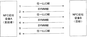
Fig. 4 shows how to use the SYMM frame.With reference to this accompanying drawing,
1. device A is sent LLC frame (for example CONNECT (connection) frame) to equipment B
2. equipment B does not have anything to send, so this equipment transmits the SYMM frame to satisfy round constraint
3. device A is sent a certain LLC frame (for example UI frame) once more
4. therefore the equipment B payload that will not send needs to send the SYMM frame
5. the device A payload that also will not send, so this equipment need be submitted the SYMM frame to
6. equipment B is sent a certain data UA frame of CONNECT frame (for example corresponding to)
SYMM divides into groups to guarantee maintenance command/response scheme, and can satisfy constraint two-way time.
The NFC link management
As stated, half duplex communication link between the equipment is used strict wheel flow algorithm, and one of them equipment sends and another equipment responds with its oneself data or control information, and first equipment could send fresh information then.To have under the situation that data will send at neither one equipment, send empty frame or symmetrical primitive (SYMM).This allows transmitting apparatus when receiving equipment does not have data to send, to regain the use to link.When neither one equipment has data or control information to send, with two-way transmission SYMM primitive, and link to can be described as be idle.
The unnecessary consumption to the battery resource of portable equipment is represented in the lasting transmission of the SYMM primitive when in fact not having swap data.In this case, be desirably under the situation that does not cause communication failure and prolong the turnaround time.Yet when the transmission data, data throughout can maximize through the control that allows transmitting apparatus to regain as soon as possible link.In this case, the shortest as far as possible turnaround time is desirable.Turnaround time in the method and system adjustment receiver described herein uses to optimize battery, simultaneously maximize data throughput.
In one embodiment, time of delay or transmission delay have increased the idle time of link maintenance that makes.Be the computing relay time, in one embodiment, the turnaround time during the free time section can be regarded as the idle factor and the idle product that postpones.The idle delay is the duration.The idle factor can be calculated as follows: initial, when setting up link first, the idle factor is made as zero.When receiving SYMM primitive each time, increase the idle factor.When the primitive that receives each time except SYMM, reduce the idle factor or it is reset to zero.Turnaround time (it is the idle factor and the idle product that postpones and is not less than a little processing delay) changes between near-zero and a certain maximum, and this is by idle scaled.
T
TT=F
IdleT
Postpone
Wherein, T
Proc≤T
TT≤T
TMax
Fig. 5 has described to use timer to determine when an embodiment that should launch such as synchronous message such as SYMM primitive.The process that starts from step 500 can start during each cycle of communication process or regularly.In step 510, this process confirms whether timer expires.If use the countdown timer, then timer expires when this timer is decremented to zero.Yet it also is possible that other timers are realized, and method and system described herein can be specialized and should not be limited to specific timer realization with various hardware or software scenario.If timer expires, then in step 520, emission SYMM primitive.Synchronous or the status message of other types also can send like the required strategic point of specific protocol.
If the nearest great majority of equipment receive the control primitive except SYMM primitive, and do not receive information frame recently, then the turnaround time can be confirmed according to the type of received control primitive and through this locality realization concern item.Receiver confirms whether received message is the message that is pre corresponding to postponing.For example, can use look-up table need to confirm the control primitive of adjustment turnaround time timer or all kinds of message.
In one embodiment, receiver confirms whether have unsettled affirmation or outgoing data in its formation.If there is not outgoing data, then the emission of SYMM primitive postpones according to the value of being confirmed by the type or the state of received message.This delay is confirmed to get final product by the table corresponding to the length of delay of various selected message or type of message.Perhaps, delay can be confirmed according to slip ratio, mathematical relationship or any amount of additive method.
Fig. 6 and Fig. 7 described method and system described herein, the exemplary realization in half-duplex peer-to-peer communications environment.In step 600, divide into groups by first equipment receiving data, and in step 610, this process confirms whether the designation data transmission is carried out in this packet.If then transmission delay is made as zero in step 620.If this packet not designation data transmission is carried out, then in step 630, this process confirms that whether this packet indicates link is idle.For example, this packet can be " I am movable " message that indication transmitting apparatus ongoing communication does not still have data to send.If link is idle, then increase delay in step 640.If link is not idle, this indication possibly receive control divides into groups, and the type that then can be depending on received control data reduces delay or it is made as zero.This process can be made this according to aforesaid look-up table or additive method and confirmed.Postponing also can to realize paying close attention to item through this locality confirms.
Proceed to Fig. 7, in step 700, this process can confirm subsequently whether receiving equipment has unsettled affirmation or outgoing data in its formation.If then should divide into groups in step 710 emission.If not, then in step 720, this process confirms whether received grouping needs special processing, that is, this grouping is pre corresponding to delay.As stated, this delay is confirmed to get final product by the table corresponding to the length of delay of various selected message or type of message.Perhaps, delay can be confirmed according to slip ratio, mathematical relationship or any amount of additive method.If there is not outgoing data,, then will send synchronization message if then confirm that in step 740 time of delay, section expired.
In an exemplary embodiment, when receiving CONN (connection) primitive and when not having unsettled affirmation or data, do not realize that the typical receiver of method described herein and process possibly respond with SYMM primitive immediately in queuing.In one embodiment, postpone the emission of SYMM primitive so that the link manager of receiver can be handled connection request and generation response (but time of delay is not long to the overtime requirement of violation receiver).Although be not that the LLCP standard is necessary, allow receiver before responding, delay to be set and to reduce the number of times and otherwise the quantity of the necessary SYMM frame that exchanges that must come and go link according to selected high priority requests.This has improved response and battery resource utilization rate.
In another exemplary embodiment, when receiving receiver not ready (RNR) primitive, can be through reducing with the delayed delivery receiver ready (RR) that reduces or minimizing the link turnaround time so that remote peer can be removed its busy condition.And counter-intuitive as if busy condition can reduce the turnaround time.But can find out that throughput is through being minimized in remote peer and can receiving once more and this peer-to-peer can using RR primitive to notify the delay after its no longer busy moment of other end points to be improved.
According to the preferred embodiment shown in Fig. 8 and 9,, receive NFC equipment and determine whether to receive information frame in step 800.If then in step 810, the frame branch is tasked appropriate application program, and, the idle factor is made as zero in step 815.If do not receive information frame, then in step 805, this process determines whether to receive SYMM primitive.If, increase the idle factor then in step 820.Otherwise,, reduce or the idle factor of resetting in step 825.If exist any waiting to send out control or Frame (step 900), then in step 910, stop timer, and launch according to the current control state of transmitting apparatus as soon as possible immediately or afterwards and wait to send out a frame, this process is returned then.
When receiving equipment did not treat that a control or data-message will send, LLCP code requirement equipment sent SYMM after the longest turnaround time that is deferred to appointment at the most.The method of actual time and definite time of delay is not stated in the LLCP standard yet.In a preferred embodiment, the value of time of delay was confirmed according to the type of the isl frame that receives recently before sending SYMM primitive.
If the frame designation data that receives is priority or designated frame and should accepts special processing (step 930), then use tabular value or other preordering methods to come to timer programme (step 940).In step 950, start timer, this process is returned then.
If the last frame that receives does not need special processing, then in step 960, this process confirms that whether the idle factor is greater than 0.If then use to be worth (the idle factor * free time postpones), and start timer in step 950 in step 970.Otherwise, stop timer in step 980, and at step 990 emission SYMM primitive, this process is returned subsequently.
Although the preferred embodiment in conjunction with each accompanying drawing has been described the present invention, be appreciated that and can use other similar embodiment, maybe can make amendment or add and carry out identical function of the present invention and do not deviate from the present invention said embodiment.In addition, should stress, can conceive the various computer platforms that comprise portable equipment operating system and other specific hardware/software interface system here, especially when the quantity sustainable growth of wireless networking device.Therefore, the present invention should not be limited to any single execution mode, and should explain according to the range and the scope of appended claims.
At last; Each disclosed embodiment described herein is applicable in other processor architecture, computer-based system or system virtualizationization, using; And open these embodiment have been expected clearly what this did; And therefore, the present invention should not be limited to specific embodiment described herein and should be explained more widely.
Claims (20)
1. method that is used for coordinating the data communication of half-duplex link, said method comprises:
Receive packet (600);
Confirm type of info included in the said packet;
Transmission delay is set; Wherein said transmission delay is considered said type; Said transmission delay indicates the transfer of data on the said link to reduce when movable in said type, and said transmission delay indicates the transfer of data on the said link to increase when idle in said type;
Spread out of in existence that (700) emission spreads out of grouping (710) when dividing into groups to wait to send out;
Do not spreading out of when dividing into groups to wait to send out, in the past launch synchronized packets (750) after the said transmission delay.
2. the method for claim 1 is characterized in that, also comprises using timer to confirm that said transmission delay, said timer also comprise the idle factor and the idle product that postpones.
3. method as claimed in claim 2 is characterized in that, the said idle factor is calculated as follows:
When setting up said link first, the said idle factor is made as zero;
Indicate the transfer of data on the said link to increase the said idle factor when idle in said type; And
Indicate the transfer of data on the said link to reduce the said idle factor when movable in said type.
4. method as claimed in claim 3 is characterized in that, the said idle factor indicates the transfer of data on the said link to be set as predetermined value when dividing into groups for movable and said type comprise control data in said type.
5. method as claimed in claim 4 is characterized in that, said emission also comprises:
Start said timer greater than zero the time in the said idle factor, and
Emission synchronized packets when said timer expires.
6. method as claimed in claim 4 is characterized in that, said predetermined value is at least one in the following: based on the priority of said packet, the random time section, consult with second equipment, slip ratio or mathematical relationship.
7. method that is used for coordinating the data communication of near-field communication link, said method comprises:
Receiving data frames;
Confirm type of info included in the said Frame;
When said type is information frame, transmission delay is made as zero (815), when said type is synchronization frame, increases said transmission delay (820), otherwise said transmission delay is made as predeterminated level;
(900) emission spreads out of frame (920) when existing at least one to spread out of frame and wait to send out; And
When not spreading out of frame and wait to send out (900), in the past launch synchronization message (990) after the said transmission delay.
8. method as claimed in claim 7 also comprises and uses timer to confirm that said transmission delay, said timer also comprise the idle factor and the idle product that postpones.
9. method as claimed in claim 8 is characterized in that, the said idle factor is calculated as follows:
When setting up link first, the said idle factor is made as zero;
, said type increases the said idle factor when being synchronization frame; And
Otherwise reduce the said idle factor or it is made as zero.
10. method as claimed in claim 9 is characterized in that, the said idle factor is set as predetermined value when said type is control frame.
11. method as claimed in claim 10 is characterized in that, said emission also comprises:
Start said timer greater than zero the time in the said idle factor, and
Emission synchronization frame when said timer expires.
12. method as claimed in claim 10 is characterized in that, the said idle factor is confirmed according in the following at least one: the priority of mathematical relationship, said Frame or random time section.
13. method as claimed in claim 7 is characterized in that, said transmission delay is consulted with second equipment.
14. a near-field communication equipment, said equipment comprises:
The receiver that is used for receiving data frames;
The transmitter that is used for transmit data frames; And
The transmission control assembly, it is used for:
Confirm type of info included in the said Frame, when said type is information frame, transmission delay is made as zero, when said type is synchronization frame, increase said delay, otherwise said delay is made as predeterminated level;
Spread out of frame having existed at least one to spread out of to have ordered said transmitter in the past when frame is waited to send out said delays back to launch; And
Do not spread out of ordered said transmitter in the past when frame is waited to send out said delays back launch synchronization message.
15. equipment as claimed in claim 14 is characterized in that, said transmission delay also comprises timer, and said timer comprises the idle factor and the idle product that postpones.
16. equipment as claimed in claim 15 is characterized in that, the said idle factor is calculated as follows:
When setting up link first, the said idle factor is made as zero;
, said type increases the said idle factor when being synchronization frame; And
Otherwise reduce the said idle factor or it is made as zero.
17. equipment as claimed in claim 16 is characterized in that, the said idle factor is set as predetermined value when said type is control frame.
18. equipment as claimed in claim 17 is characterized in that, said transmission control assembly also starts said timer in the said idle factor greater than zero the time, and when said timer expires the emission synchronization frame.
19. equipment as claimed in claim 17 is characterized in that, the said idle factor is confirmed according in the following at least one: the priority of mathematical relationship, said Frame or random time section.
20. equipment as claimed in claim 14 is characterized in that, said transmission delay is consulted with second equipment.
Applications Claiming Priority (5)
| Application Number | Priority Date | Filing Date | Title |
|---|---|---|---|
| US93982707P | 2007-05-23 | 2007-05-23 | |
| US60/939,827 | 2007-05-23 | ||
| US11/855,913 US8400913B2 (en) | 2007-05-23 | 2007-09-14 | Method for optimizing near field links |
| US11/855,913 | 2007-09-14 | ||
| PCT/US2008/063859 WO2008147728A1 (en) | 2007-05-23 | 2008-05-16 | Method for optimizing near field links |
Publications (2)
| Publication Number | Publication Date |
|---|---|
| CN101682405A CN101682405A (en) | 2010-03-24 |
| CN101682405B true CN101682405B (en) | 2012-12-12 |
Family
ID=40072299
Family Applications (1)
| Application Number | Title | Priority Date | Filing Date |
|---|---|---|---|
| CN2008800170221A Active CN101682405B (en) | 2007-05-23 | 2008-05-16 | Method for optimizing near field links |
Country Status (13)
| Country | Link |
|---|---|
| US (2) | US8400913B2 (en) |
| EP (1) | EP2149208B1 (en) |
| JP (1) | JP5301533B2 (en) |
| KR (1) | KR101497165B1 (en) |
| CN (1) | CN101682405B (en) |
| AU (1) | AU2008256962B2 (en) |
| BR (1) | BRPI0810767B1 (en) |
| CA (1) | CA2684287C (en) |
| IL (1) | IL201477A (en) |
| MX (1) | MX2009012232A (en) |
| RU (1) | RU2464710C2 (en) |
| TW (2) | TWI533636B (en) |
| WO (1) | WO2008147728A1 (en) |
Families Citing this family (29)
| Publication number | Priority date | Publication date | Assignee | Title |
|---|---|---|---|---|
| US8264991B2 (en) * | 2007-04-27 | 2012-09-11 | Samsung Electronics Co., Ltd. | System and method for improving symmetry in data transfer in LLC layer of peer to peer NFC device |
| US8400913B2 (en) | 2007-05-23 | 2013-03-19 | Microsoft Corporation | Method for optimizing near field links |
| US8385823B2 (en) * | 2007-10-03 | 2013-02-26 | Samsung Electronics Co., Ltd | Method and system for communication in near field communication network |
| JP2010009521A (en) * | 2008-06-30 | 2010-01-14 | Canon Inc | Image providing apparatus, image output apparatus, and image output system |
| JP4720899B2 (en) * | 2008-11-27 | 2011-07-13 | ソニー株式会社 | COMMUNICATION DEVICE, COMMUNICATION METHOD, PROGRAM, AND COMMUNICATION SYSTEM |
| JP5435456B2 (en) * | 2009-03-29 | 2014-03-05 | 雅英 田中 | Cell phone, charger and digital photo frame |
| US8068011B1 (en) | 2010-08-27 | 2011-11-29 | Q Street, LLC | System and method for interactive user-directed interfacing between handheld devices and RFID media |
| US8548380B2 (en) * | 2011-06-10 | 2013-10-01 | Broadcom Corporation | Communications device for intelligently routing information among multiple user interfaces |
| US8942628B2 (en) | 2011-11-28 | 2015-01-27 | Qualcomm Incorporated | Reducing power consumption for connection establishment in near field communication systems |
| US8903312B2 (en) | 2011-11-28 | 2014-12-02 | Qualcomm Incorporated | Modified connection establishment for reducing power consumption in near field communication systems |
| US9370040B2 (en) * | 2011-12-27 | 2016-06-14 | Qualcomm Incorporated | Methods and apparatus for improving NFC LLCP partitioning |
| US9214988B2 (en) | 2012-02-06 | 2015-12-15 | Qualcomm Incorporated | Methods and apparatus for improving peer communications using an active communication mode |
| US9113373B2 (en) * | 2012-04-10 | 2015-08-18 | Qualcomm Incorporated | Methods and apparatus for improving peer communications using an active communication mode |
| US9270339B2 (en) * | 2012-08-29 | 2016-02-23 | Intel Corporation | Method, apparatus and system of recovering an operating system on a portable communication device |
| FR3001309B1 (en) | 2013-01-24 | 2015-01-09 | St Microelectronics Rousset | METHOD OF PROCESSING TRANSMISSION ERRORS, IN PARTICULAR THOSE RESULTING FROM NOISE, IN CONTACTLESS COMMUNICATION BETWEEN A CARD AND A READER. |
| CN103973340B (en) * | 2013-01-29 | 2016-05-25 | 华为终端有限公司 | Near field communication method and near-field communication equipment |
| KR20150143447A (en) * | 2013-02-21 | 2015-12-23 | 와이즈-세크 리미티드 | Proximity Detection |
| CN104065399B (en) * | 2013-03-20 | 2017-09-01 | 华为终端有限公司 | Consult method, equipment and the system of mode of operation |
| JP6201641B2 (en) * | 2013-10-29 | 2017-09-27 | ソニー株式会社 | Information processing apparatus, imaging apparatus, imaging system, information processing apparatus control method, imaging apparatus control method, and program |
| US9345050B2 (en) * | 2014-02-21 | 2016-05-17 | Sony Corporation | NFC collision avoidance with controllable NFC transmission delay timing |
| US9312921B2 (en) | 2014-02-21 | 2016-04-12 | Sony Corporation | Retrieving/authorizing content on user equipment based on information from connectable accessory with NFC circuit |
| US9408238B2 (en) * | 2014-02-21 | 2016-08-02 | Sony Corporation | Removable conductive layer that shields and/or shorts nodes of an NFC circuit to control transmissions therefrom |
| JP6448334B2 (en) * | 2014-12-02 | 2019-01-09 | キヤノン株式会社 | Display control device and control method of display control device |
| KR101993959B1 (en) | 2016-07-21 | 2019-06-27 | 이도훈 | Unificated Near Field Communication system using mobile, and the method therefor |
| JP6414283B2 (en) * | 2017-06-28 | 2018-10-31 | ブラザー工業株式会社 | Communication device |
| US20190098434A1 (en) * | 2017-09-25 | 2019-03-28 | Kabushiki Kaisha Toshiba | Information processing apparatus, recording medium, and information exchange method |
| CN108200601A (en) * | 2017-11-30 | 2018-06-22 | 大连理工大学 | A kind of multilink selection method based on data priority, link state and traffic current density |
| KR102625778B1 (en) * | 2018-03-21 | 2024-01-16 | 한국전자통신연구원 | ARQ feedback method when ARQ is used in Half duplex mode in Proximity-1 system |
| CN116203362B (en) * | 2023-02-10 | 2023-09-19 | 深圳市云帆自动化技术有限公司 | Distribution panel state monitoring system |
Citations (3)
| Publication number | Priority date | Publication date | Assignee | Title |
|---|---|---|---|---|
| US5822537A (en) * | 1994-02-24 | 1998-10-13 | At&T Corp. | Multimedia networked system detecting congestion by monitoring buffers' threshold and compensating by reducing video transmittal rate then reducing audio playback rate |
| CN1267408A (en) * | 1997-05-16 | 2000-09-20 | 夸尔柯姆股份有限公司 | Method of and apparatus for detecting and preventing message collisions in communication system |
| CN1692566A (en) * | 2002-12-17 | 2005-11-02 | 索尼株式会社 | Communication system, communication method, and data processing device |
Family Cites Families (30)
| Publication number | Priority date | Publication date | Assignee | Title |
|---|---|---|---|---|
| ZA925728B (en) * | 1991-08-01 | 1993-04-28 | City Communications Ltd | Improvements in a radio communication system |
| US5437057A (en) * | 1992-12-03 | 1995-07-25 | Xerox Corporation | Wireless communications using near field coupling |
| US5822538A (en) * | 1996-11-20 | 1998-10-13 | Advanced Micro Devices, Inc. | Method and apparatus for prioritizing traffic in half-duplex networks by selecting delay intervals from fixed ranges |
| US6212175B1 (en) * | 1997-04-22 | 2001-04-03 | Telxon Corporation | Method to sustain TCP connection |
| KR100542936B1 (en) * | 1997-10-06 | 2006-03-23 | 마츠시타 덴끼 산교 가부시키가이샤 | Information transmission control apparatus for transmitting same information to a plurality of destinations, and information reception apparatus for receiving information from information transmission control apparatus |
| JP3271595B2 (en) * | 1998-12-18 | 2002-04-02 | 三菱マテリアル株式会社 | Mobile radio, radio server, and recording medium therefor |
| US6424820B1 (en) * | 1999-04-02 | 2002-07-23 | Interval Research Corporation | Inductively coupled wireless system and method |
| US7046382B1 (en) * | 1999-06-30 | 2006-05-16 | Conexant Systems, Inc. | Network latency recovery for internet gateways |
| JP4015428B2 (en) * | 2001-05-16 | 2007-11-28 | 株式会社日立コミュニケーションテクノロジー | RADIO BASE STATION / WIRELESS BASE STATION CONTROL DEVICE, RADIO TERMINAL, AND STATE CONTROL METHOD HAVING IN-ACTIVITY TIMER |
| IL159460A0 (en) | 2001-07-09 | 2004-06-01 | Novo Nordisk As | Method and system for controlling data information between two portable medical apparatuses |
| EP1634162B1 (en) * | 2003-01-31 | 2010-07-14 | Visto Corporation | Asynchronous real-time retrieval of data |
| JP2005204254A (en) * | 2004-01-19 | 2005-07-28 | Toshiba Corp | Radio base station. radio terminal station, and radio communication method |
| US7426569B2 (en) * | 2004-02-25 | 2008-09-16 | Research In Motion Limited | System and method for maintaining a network connection |
| DE102004014624A1 (en) * | 2004-03-25 | 2005-10-13 | Daimlerchrysler Ag | Local transmission system for a means of transport |
| US7457669B2 (en) * | 2004-06-17 | 2008-11-25 | Cardiac Pacemakers, Inc. | On-demand retransmission of data with an implantable medical device |
| US7375616B2 (en) * | 2004-09-08 | 2008-05-20 | Nokia Corporation | Electronic near field communication enabled multifunctional device and method of its operation |
| EP3154206A1 (en) * | 2004-10-29 | 2017-04-12 | Sony Deutschland Gmbh | Method for operating a near field communication system |
| GB0501115D0 (en) | 2005-01-19 | 2005-02-23 | Innovision Res & Tech Plc | Combined power coupling and rf communication apparatus |
| EP1864470A1 (en) * | 2005-02-11 | 2007-12-12 | Axalto Inc. | System and method for data communications allowing slave devices to be network peers |
| US20070026825A1 (en) * | 2005-02-24 | 2007-02-01 | Innovision Research & Technology Plc | NFC device and apparatus |
| US7907954B2 (en) * | 2005-03-23 | 2011-03-15 | Nokia Corporation | System and method for dynamic interface management |
| US7202825B2 (en) * | 2005-09-15 | 2007-04-10 | Motorola, Inc. | Wireless communication device with integrated battery/antenna system |
| US7567791B2 (en) * | 2005-09-19 | 2009-07-28 | Qualcomm Incorporated | Wireless terminal methods and apparatus for use in a wireless communications system that uses a multi-mode base station |
| US20070099679A1 (en) * | 2005-11-01 | 2007-05-03 | Mikko Saarisalo | Wireless near field communication control using device state or orientation |
| GB0526029D0 (en) * | 2005-12-21 | 2006-02-01 | Nokia Corp | Managing connections in a wireless communications network |
| US7746810B2 (en) * | 2006-03-31 | 2010-06-29 | Intel Corporation | Wake on wireless network techniques |
| US8260372B2 (en) * | 2006-06-30 | 2012-09-04 | Nokia Corporation | Traffic monitoring for regulating states of a terminal |
| US7684346B2 (en) * | 2006-12-29 | 2010-03-23 | Nokia Corporation | Communications control for extending the period over which a terminal is able to have an open connection with a host accessible via a packet data network |
| US7860469B2 (en) * | 2007-03-19 | 2010-12-28 | Intel Corporation | Sleep optimization for mobile devices in a wireless network |
| US8400913B2 (en) | 2007-05-23 | 2013-03-19 | Microsoft Corporation | Method for optimizing near field links |
-
2007
- 2007-09-14 US US11/855,913 patent/US8400913B2/en active Active
-
2008
- 2008-05-16 KR KR1020097023868A patent/KR101497165B1/en active IP Right Grant
- 2008-05-16 EP EP08769491.5A patent/EP2149208B1/en active Active
- 2008-05-16 AU AU2008256962A patent/AU2008256962B2/en active Active
- 2008-05-16 TW TW103114295A patent/TWI533636B/en not_active IP Right Cessation
- 2008-05-16 RU RU2009143001/07A patent/RU2464710C2/en active
- 2008-05-16 CN CN2008800170221A patent/CN101682405B/en active Active
- 2008-05-16 JP JP2010509473A patent/JP5301533B2/en active Active
- 2008-05-16 BR BRPI0810767A patent/BRPI0810767B1/en active IP Right Grant
- 2008-05-16 WO PCT/US2008/063859 patent/WO2008147728A1/en active Application Filing
- 2008-05-16 CA CA2684287A patent/CA2684287C/en active Active
- 2008-05-16 TW TW097118160A patent/TWI445338B/en not_active IP Right Cessation
- 2008-05-16 MX MX2009012232A patent/MX2009012232A/en active IP Right Grant
-
2009
- 2009-10-13 IL IL201477A patent/IL201477A/en active IP Right Grant
-
2013
- 2013-03-15 US US13/837,258 patent/US8780714B2/en active Active
Patent Citations (3)
| Publication number | Priority date | Publication date | Assignee | Title |
|---|---|---|---|---|
| US5822537A (en) * | 1994-02-24 | 1998-10-13 | At&T Corp. | Multimedia networked system detecting congestion by monitoring buffers' threshold and compensating by reducing video transmittal rate then reducing audio playback rate |
| CN1267408A (en) * | 1997-05-16 | 2000-09-20 | 夸尔柯姆股份有限公司 | Method of and apparatus for detecting and preventing message collisions in communication system |
| CN1692566A (en) * | 2002-12-17 | 2005-11-02 | 索尼株式会社 | Communication system, communication method, and data processing device |
Also Published As
| Publication number | Publication date |
|---|---|
| CA2684287A1 (en) | 2008-12-04 |
| EP2149208B1 (en) | 2018-11-28 |
| KR101497165B1 (en) | 2015-02-27 |
| JP2010528535A (en) | 2010-08-19 |
| BRPI0810767B1 (en) | 2020-04-07 |
| US20130230082A1 (en) | 2013-09-05 |
| RU2464710C2 (en) | 2012-10-20 |
| EP2149208A1 (en) | 2010-02-03 |
| US20080291852A1 (en) | 2008-11-27 |
| IL201477A0 (en) | 2010-05-31 |
| TW201448501A (en) | 2014-12-16 |
| IL201477A (en) | 2014-06-30 |
| US8400913B2 (en) | 2013-03-19 |
| MX2009012232A (en) | 2009-12-01 |
| TWI533636B (en) | 2016-05-11 |
| AU2008256962B2 (en) | 2011-06-09 |
| CA2684287C (en) | 2015-08-04 |
| RU2009143001A (en) | 2011-05-27 |
| TW200901648A (en) | 2009-01-01 |
| AU2008256962A1 (en) | 2008-12-04 |
| JP5301533B2 (en) | 2013-09-25 |
| EP2149208A4 (en) | 2017-03-01 |
| KR20100017105A (en) | 2010-02-16 |
| CN101682405A (en) | 2010-03-24 |
| BRPI0810767A2 (en) | 2014-10-29 |
| US8780714B2 (en) | 2014-07-15 |
| WO2008147728A1 (en) | 2008-12-04 |
| TWI445338B (en) | 2014-07-11 |
Similar Documents
| Publication | Publication Date | Title |
|---|---|---|
| CN101682405B (en) | Method for optimizing near field links | |
| CN1832475B (en) | Reliable request-response messaging over a request-response transport | |
| CN102685203A (en) | Method and equipment for data resource transmission | |
| CN106688277A (en) | Efficient centralized resource and schedule management in time slotted channel hopping networks | |
| EP1986340B1 (en) | System and method for improving symmetry in data tranfer in llc layer of peer to peer nfc device | |
| JP6403556B2 (en) | Gateway device, smart meter and wireless mesh network | |
| CN111510493A (en) | Distributed data transmission method and device | |
| US20120207155A1 (en) | System and method for scalable, efficient, and robust system management communications via vendor defined extensions | |
| CN113014499B (en) | Data transmission method and device, electronic equipment and storage medium | |
| CN102761780A (en) | Method for obtaining media metadata by intelligent remote controller to | |
| CN105516265A (en) | Short message transmission method and apparatus | |
| WO2017040948A1 (en) | Enabling time flexibility for block transfer in coap protocol | |
| US9294150B2 (en) | Information relay mechanism using proximity communication | |
| CN107483424B (en) | Processing method and device of remote procedure call protocol | |
| CN101860544A (en) | Transmitting system and method of session initiation protocol message | |
| CN104506642A (en) | Client message efficient transceiving and processing method and system | |
| CN107733983A (en) | Internet of Things communication means and the first repeater | |
| US20240015785A1 (en) | Systems, devices, and methods related to conserving communication bandwidth with spare time schedule | |
| CN104052646A (en) | Photo identification-based instant communication method and system, server | |
| CN114416383A (en) | Multi-process communication method and device | |
| CN116868676A (en) | Communication method, electronic device, and storage medium | |
| CN116830679A (en) | Communication method, electronic device, and storage medium | |
| CN104104663A (en) | Distributed invocation framework, and devices and data transmission method thereof | |
| CN107750469A (en) | Seal device, its operating method and recording medium | |
| CN101729437A (en) | Network sharing system, information transfer method thereof and machine readable media thereof |
Legal Events
| Date | Code | Title | Description |
|---|---|---|---|
| C06 | Publication | ||
| PB01 | Publication | ||
| C10 | Entry into substantive examination | ||
| SE01 | Entry into force of request for substantive examination | ||
| C14 | Grant of patent or utility model | ||
| GR01 | Patent grant | ||
| ASS | Succession or assignment of patent right |
Owner name: MICROSOFT TECHNOLOGY LICENSING LLC Free format text: FORMER OWNER: MICROSOFT CORP. Effective date: 20150528 |
|
| C41 | Transfer of patent application or patent right or utility model | ||
| TR01 | Transfer of patent right |
Effective date of registration: 20150528 Address after: Washington State Patentee after: Micro soft technique license Co., Ltd Address before: Washington State Patentee before: Microsoft Corp. |