CN101772321B - Puncture instrument - Google Patents
Puncture instrument Download PDFInfo
- Publication number
- CN101772321B CN101772321B CN2008801014288A CN200880101428A CN101772321B CN 101772321 B CN101772321 B CN 101772321B CN 2008801014288 A CN2008801014288 A CN 2008801014288A CN 200880101428 A CN200880101428 A CN 200880101428A CN 101772321 B CN101772321 B CN 101772321B
- Authority
- CN
- China
- Prior art keywords
- perforator
- hub
- arm
- pusher
- distal end
- Prior art date
- Legal status (The legal status is an assumption and is not a legal conclusion. Google has not performed a legal analysis and makes no representation as to the accuracy of the status listed.)
- Active
Links
Images


Classifications
-
- A—HUMAN NECESSITIES
- A61—MEDICAL OR VETERINARY SCIENCE; HYGIENE
- A61B—DIAGNOSIS; SURGERY; IDENTIFICATION
- A61B5/00—Measuring for diagnostic purposes; Identification of persons
- A61B5/15—Devices for taking samples of blood
- A61B5/150007—Details
- A61B5/150374—Details of piercing elements or protective means for preventing accidental injuries by such piercing elements
- A61B5/150534—Design of protective means for piercing elements for preventing accidental needle sticks, e.g. shields, caps, protectors, axially extensible sleeves, pivotable protective sleeves
- A61B5/15058—Joining techniques used for protective means
- A61B5/15061—Joining techniques used for protective means by material engagement, e.g. welding, bonding
-
- A—HUMAN NECESSITIES
- A61—MEDICAL OR VETERINARY SCIENCE; HYGIENE
- A61B—DIAGNOSIS; SURGERY; IDENTIFICATION
- A61B5/00—Measuring for diagnostic purposes; Identification of persons
- A61B5/15—Devices for taking samples of blood
- A61B5/150007—Details
- A61B5/150015—Source of blood
- A61B5/150022—Source of blood for capillary blood or interstitial fluid
-
- A—HUMAN NECESSITIES
- A61—MEDICAL OR VETERINARY SCIENCE; HYGIENE
- A61B—DIAGNOSIS; SURGERY; IDENTIFICATION
- A61B5/00—Measuring for diagnostic purposes; Identification of persons
- A61B5/15—Devices for taking samples of blood
- A61B5/150007—Details
- A61B5/150175—Adjustment of penetration depth
- A61B5/150183—Depth adjustment mechanism using end caps mounted at the distal end of the sampling device, i.e. the end-caps are adjustably positioned relative to the piercing device housing for example by rotating or screwing
-
- A—HUMAN NECESSITIES
- A61—MEDICAL OR VETERINARY SCIENCE; HYGIENE
- A61B—DIAGNOSIS; SURGERY; IDENTIFICATION
- A61B5/00—Measuring for diagnostic purposes; Identification of persons
- A61B5/15—Devices for taking samples of blood
- A61B5/150007—Details
- A61B5/150206—Construction or design features not otherwise provided for; manufacturing or production; packages; sterilisation of piercing element, piercing device or sampling device
- A61B5/150259—Improved gripping, e.g. with high friction pattern or projections on the housing surface or an ergonometric shape
-
- A—HUMAN NECESSITIES
- A61—MEDICAL OR VETERINARY SCIENCE; HYGIENE
- A61B—DIAGNOSIS; SURGERY; IDENTIFICATION
- A61B5/00—Measuring for diagnostic purposes; Identification of persons
- A61B5/15—Devices for taking samples of blood
- A61B5/150007—Details
- A61B5/150206—Construction or design features not otherwise provided for; manufacturing or production; packages; sterilisation of piercing element, piercing device or sampling device
- A61B5/150312—Sterilisation of piercing elements, piercing devices or sampling devices
- A61B5/150335—Sterilisation of piercing elements, piercing devices or sampling devices by radiation
-
- A—HUMAN NECESSITIES
- A61—MEDICAL OR VETERINARY SCIENCE; HYGIENE
- A61B—DIAGNOSIS; SURGERY; IDENTIFICATION
- A61B5/00—Measuring for diagnostic purposes; Identification of persons
- A61B5/15—Devices for taking samples of blood
- A61B5/150007—Details
- A61B5/150374—Details of piercing elements or protective means for preventing accidental injuries by such piercing elements
- A61B5/150381—Design of piercing elements
- A61B5/150412—Pointed piercing elements, e.g. needles, lancets for piercing the skin
-
- A—HUMAN NECESSITIES
- A61—MEDICAL OR VETERINARY SCIENCE; HYGIENE
- A61B—DIAGNOSIS; SURGERY; IDENTIFICATION
- A61B5/00—Measuring for diagnostic purposes; Identification of persons
- A61B5/15—Devices for taking samples of blood
- A61B5/150007—Details
- A61B5/150374—Details of piercing elements or protective means for preventing accidental injuries by such piercing elements
- A61B5/150381—Design of piercing elements
- A61B5/150503—Single-ended needles
- A61B5/150519—Details of construction of hub, i.e. element used to attach the single-ended needle to a piercing device or sampling device
-
- A—HUMAN NECESSITIES
- A61—MEDICAL OR VETERINARY SCIENCE; HYGIENE
- A61B—DIAGNOSIS; SURGERY; IDENTIFICATION
- A61B5/00—Measuring for diagnostic purposes; Identification of persons
- A61B5/15—Devices for taking samples of blood
- A61B5/150007—Details
- A61B5/150374—Details of piercing elements or protective means for preventing accidental injuries by such piercing elements
- A61B5/150534—Design of protective means for piercing elements for preventing accidental needle sticks, e.g. shields, caps, protectors, axially extensible sleeves, pivotable protective sleeves
- A61B5/150541—Breakable protectors, e.g. caps, shields or sleeves, i.e. protectors separated destructively, e.g. by breaking a connecting area
- A61B5/150549—Protectors removed by rotational movement, e.g. torsion or screwing
-
- A—HUMAN NECESSITIES
- A61—MEDICAL OR VETERINARY SCIENCE; HYGIENE
- A61B—DIAGNOSIS; SURGERY; IDENTIFICATION
- A61B5/00—Measuring for diagnostic purposes; Identification of persons
- A61B5/15—Devices for taking samples of blood
- A61B5/150007—Details
- A61B5/150374—Details of piercing elements or protective means for preventing accidental injuries by such piercing elements
- A61B5/150534—Design of protective means for piercing elements for preventing accidental needle sticks, e.g. shields, caps, protectors, axially extensible sleeves, pivotable protective sleeves
- A61B5/150694—Procedure for removing protection means at the time of piercing
- A61B5/150717—Procedure for removing protection means at the time of piercing manually removed
-
- A—HUMAN NECESSITIES
- A61—MEDICAL OR VETERINARY SCIENCE; HYGIENE
- A61B—DIAGNOSIS; SURGERY; IDENTIFICATION
- A61B5/00—Measuring for diagnostic purposes; Identification of persons
- A61B5/15—Devices for taking samples of blood
- A61B5/150007—Details
- A61B5/150885—Preventing re-use
- A61B5/150916—Preventing re-use by blocking components, e.g. piston, driving device or fluid passageway
-
- A—HUMAN NECESSITIES
- A61—MEDICAL OR VETERINARY SCIENCE; HYGIENE
- A61B—DIAGNOSIS; SURGERY; IDENTIFICATION
- A61B5/00—Measuring for diagnostic purposes; Identification of persons
- A61B5/15—Devices for taking samples of blood
- A61B5/151—Devices specially adapted for taking samples of capillary blood, e.g. by lancets, needles or blades
- A61B5/15101—Details
- A61B5/15103—Piercing procedure
- A61B5/15105—Purely manual piercing, i.e. the user pierces the skin without the assistance of any driving means or driving devices
-
- A—HUMAN NECESSITIES
- A61—MEDICAL OR VETERINARY SCIENCE; HYGIENE
- A61B—DIAGNOSIS; SURGERY; IDENTIFICATION
- A61B5/00—Measuring for diagnostic purposes; Identification of persons
- A61B5/15—Devices for taking samples of blood
- A61B5/151—Devices specially adapted for taking samples of capillary blood, e.g. by lancets, needles or blades
- A61B5/15101—Details
- A61B5/15103—Piercing procedure
- A61B5/15107—Piercing being assisted by a triggering mechanism
- A61B5/15113—Manually triggered, i.e. the triggering requires a deliberate action by the user such as pressing a drive button
-
- A—HUMAN NECESSITIES
- A61—MEDICAL OR VETERINARY SCIENCE; HYGIENE
- A61B—DIAGNOSIS; SURGERY; IDENTIFICATION
- A61B5/00—Measuring for diagnostic purposes; Identification of persons
- A61B5/15—Devices for taking samples of blood
- A61B5/151—Devices specially adapted for taking samples of capillary blood, e.g. by lancets, needles or blades
- A61B5/15101—Details
- A61B5/15115—Driving means for propelling the piercing element to pierce the skin, e.g. comprising mechanisms based on shape memory alloys, magnetism, solenoids, piezoelectric effect, biased elements, resilient elements, vacuum or compressed fluids
- A61B5/15117—Driving means for propelling the piercing element to pierce the skin, e.g. comprising mechanisms based on shape memory alloys, magnetism, solenoids, piezoelectric effect, biased elements, resilient elements, vacuum or compressed fluids comprising biased elements, resilient elements or a spring, e.g. a helical spring, leaf spring, or elastic strap
-
- A—HUMAN NECESSITIES
- A61—MEDICAL OR VETERINARY SCIENCE; HYGIENE
- A61B—DIAGNOSIS; SURGERY; IDENTIFICATION
- A61B5/00—Measuring for diagnostic purposes; Identification of persons
- A61B5/15—Devices for taking samples of blood
- A61B5/151—Devices specially adapted for taking samples of capillary blood, e.g. by lancets, needles or blades
- A61B5/15101—Details
- A61B5/15115—Driving means for propelling the piercing element to pierce the skin, e.g. comprising mechanisms based on shape memory alloys, magnetism, solenoids, piezoelectric effect, biased elements, resilient elements, vacuum or compressed fluids
- A61B5/15123—Driving means for propelling the piercing element to pierce the skin, e.g. comprising mechanisms based on shape memory alloys, magnetism, solenoids, piezoelectric effect, biased elements, resilient elements, vacuum or compressed fluids comprising magnets or solenoids
-
- A—HUMAN NECESSITIES
- A61—MEDICAL OR VETERINARY SCIENCE; HYGIENE
- A61B—DIAGNOSIS; SURGERY; IDENTIFICATION
- A61B5/00—Measuring for diagnostic purposes; Identification of persons
- A61B5/15—Devices for taking samples of blood
- A61B5/151—Devices specially adapted for taking samples of capillary blood, e.g. by lancets, needles or blades
- A61B5/15101—Details
- A61B5/15115—Driving means for propelling the piercing element to pierce the skin, e.g. comprising mechanisms based on shape memory alloys, magnetism, solenoids, piezoelectric effect, biased elements, resilient elements, vacuum or compressed fluids
- A61B5/15125—Driving means for propelling the piercing element to pierce the skin, e.g. comprising mechanisms based on shape memory alloys, magnetism, solenoids, piezoelectric effect, biased elements, resilient elements, vacuum or compressed fluids comprising a vacuum or compressed fluids
-
- A—HUMAN NECESSITIES
- A61—MEDICAL OR VETERINARY SCIENCE; HYGIENE
- A61B—DIAGNOSIS; SURGERY; IDENTIFICATION
- A61B5/00—Measuring for diagnostic purposes; Identification of persons
- A61B5/15—Devices for taking samples of blood
- A61B5/151—Devices specially adapted for taking samples of capillary blood, e.g. by lancets, needles or blades
- A61B5/15101—Details
- A61B5/15126—Means for controlling the lancing movement, e.g. 2D- or 3D-shaped elements, tooth-shaped elements or sliding guides
- A61B5/15128—Means for controlling the lancing movement, e.g. 2D- or 3D-shaped elements, tooth-shaped elements or sliding guides comprising 2D- or 3D-shaped elements, e.g. cams, curved guide rails or threads
-
- A—HUMAN NECESSITIES
- A61—MEDICAL OR VETERINARY SCIENCE; HYGIENE
- A61B—DIAGNOSIS; SURGERY; IDENTIFICATION
- A61B5/00—Measuring for diagnostic purposes; Identification of persons
- A61B5/15—Devices for taking samples of blood
- A61B5/151—Devices specially adapted for taking samples of capillary blood, e.g. by lancets, needles or blades
- A61B5/15101—Details
- A61B5/15126—Means for controlling the lancing movement, e.g. 2D- or 3D-shaped elements, tooth-shaped elements or sliding guides
- A61B5/1513—Means for controlling the lancing movement, e.g. 2D- or 3D-shaped elements, tooth-shaped elements or sliding guides comprising linear sliding guides
-
- A—HUMAN NECESSITIES
- A61—MEDICAL OR VETERINARY SCIENCE; HYGIENE
- A61B—DIAGNOSIS; SURGERY; IDENTIFICATION
- A61B5/00—Measuring for diagnostic purposes; Identification of persons
- A61B5/15—Devices for taking samples of blood
- A61B5/151—Devices specially adapted for taking samples of capillary blood, e.g. by lancets, needles or blades
- A61B5/15142—Devices intended for single use, i.e. disposable
- A61B5/15144—Devices intended for single use, i.e. disposable comprising driving means, e.g. a spring, for retracting the piercing unit into the housing
Abstract
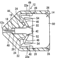
A puncture instrument (10) includes a needle assembly (44), a hub passage (16) for axially guiding a hub (42), a needle passage (18) communicating with the hub passage (16) and having a distal end opening (18a) for allowing the tip end of a needle (40) to project instantaneously therethrough, two arms (46) having first junctions (52) connected to the hub (42) and inclined rearward in a direction away from the hub (42) in an initial state, two push rods (48) connected to second junctions (54) of the arms (46) and extending rearward, a button (50) for pushing the push rods (48) forwardly, and fulcrum members (24) disposed more closely to the distal end than the arms (46) for abutment against portions of the arms (46) when the arms (46) are moved. When the push rods (48) are pushed forwardly by the button (50), the arms (46) push the needle assembly (44) forwardly, thereafter have portions thereof brought into abutment against the fulcrum members (24), and turn to pull the needle assembly (44) rearward.
Description
Technical field
The present invention relates to a kind of perforator that comprises pin, be used for that moment is stretched out pin and with pin puncture people's skin.
Background technology
Diabetics generally all is proposed by own measurement of glucose levels and carries out daily diabetes self management.Blood sugar level can be measured with the blood constituent measuring device.According to a kind of blood constituent measuring device, it is equipped with the reagent paper that has flooded reagent, reagent according to blood sample that reagent paper contacts in the glucose amount that contains change color can take place.In operation, blood sample is applied on the reagent paper, and the change color degree that reagent takes place is measured with optical means, to determine the blood sugar level in the blood sample.Demonstrate definite blood sugar level then.Another kind of blood constituent measuring device adopts electrochemical sensor to measure the blood sugar level of blood sample.
For diabetics is taken a sample to the blood of oneself, diabetics uses the perforator that has been equipped with piercing needle, and this piercing needle has the pin that can move vertically.Piercing needle is installed on the perforator in removable mode, and in the future the thrust of own elasticity body imposes on the pin of the inside, causes pin moment to stretch out and the patient's that punctures skin (for example finger, palm, arm etc.), is used to thus allow small amounts of blood flow out.After the puncture, pin is regained by response agency.
In general, perforator uses with mounted thereto piercing needle, and piercing needle uses the back to be thrown away.Though hospital and clinic have a large amount of piercing needles standby according to patient's quantity and blood glucose measurement frequency,, there is the perforator of relatively small amount to use.Therefore, if a lot of needs of patients while measurement of glucose levels, so, because there are not enough perforators to use, so all patients may spend longer measure of time blood sugar level than usual.Because all to piercing needle be installed on perforator and take off piercing needle during each the measurement from perforator, so, exist demand to simpler perforator.
No. 3795511 Japan Patent discloses a kind of simple lancet assembly, and it has made up piercing needle integratedly.Disclosed lancet assembly makes it all will install and take off piercing needle in the time will obtaining blood sample at every turn.
Summary of the invention
An object of the present invention is to provide a kind of can stably the operation and perforator simple in structure.
Perforator according to the present invention comprises: housing; Needle assembly, the hub that it can be arranged in the described housing with moving and comprise pin and keep described pin; The hub passage is used for along the described hub of axial lead, and described hub passage is arranged in the described housing; Needle passageway, its be arranged in the described housing and with described hub channel connection, described needle passageway has the distal end opening that stretch out at the tip that is used to allow described pin; At least one arm has first connecting portion that is connected to described hub at the one end, has second connecting portion at its other end, and described arm proximal end from described first connecting portion towards described housing in original state tilts; Push rod, it is incorporated into described second connecting portion and extends towards described proximal end; Pusher is used for described push rod is pushed to the distal end of described housing; And fulcrum member, be used for when the motion of described arm a part against described arm, wherein, when described push rod is pushed to described distal end by described pusher, described arm is pushed described needle assembly to described distal end, its described part is rotated against the fulcrum member and around described fulcrum member, make described arm tilt towards described distal end, thus described needle assembly is retracted towards described proximal end from described first connecting portion.
Utilize above-mentioned perforator, described needle assembly is directly promoted by described push rod, not in the centre by means of the elastomer of the described needle assembly that is used for setovering vertically, skin puncture stably, and simple in structure.After described pin skin puncture, described arm retracts described pin around described fulcrum member rotates reliably from skin.The above-mentioned term of mentioning " housing " is to use in a broad sense, and expression is as the member of perforator pedestal.
Push rod can comprise the sheet spring, its can be when pusher be pushed push rod to described distal end under the effect of arm applied force strain.If described push rod comprises the sheet spring, it just can not hinder the rotation of described arm so, therefore allows described arm more stably to operate.After described needle assembly finished its motion, described needle assembly was resiliently biased under the resilient force of described push rod and motion backward.
In original state, described arm can tilt towards described proximal end along the direction of leaving described hub, pushed away along with described pusher and when being pushed to described distal end at described push rod, described arm can rotate and tilt towards described distal end along the direction of leaving described hub around described fulcrum member.
In described first connecting portion and described second connecting portion at least one can be narrower than described arm, and can plastic deformation when described arm rotates and changes its incline direction.If at least one plastic deformation in described first connecting portion and described second connecting portion, then described pusher remains on the end of travel position with being stabilized, can back not shift to described initial position.So, can prevent that described perforator is used again.
Described hub can comprise pedestal in its proximal end part, described pedestal has the plane surface that is parallel to described arm rotational plane, and described first connecting portion is pivotally connected to described pedestal with the longitudinal axis of described hub position spaced apart by a predetermined distance on described plane.
Described pusher can comprise protruding or the concave copulae branch, but but described housing comprise when described pusher and engage first bonding part of described bonding part during at initial position and engage second bonding part of described bonding part during at the stroke terminal position when described pusher.
At described initial position, but the bonding part of described pusher engages described first bonding part, therefore can accidental movement.When described pusher is pushed hard to described distal end, but described bonding part breaks away from described first bonding part, allows described pusher and described needle assembly forcefully towards described distal end motion.Described pin therefore can be with the certain speed skin puncture.Afterwards, but described bonding part engage with described second bonding part, described pusher stably is held in place.
Described pusher can be arranged in the inner chamber that forms in the described housing with moving, and has a proximal end, when described pusher during at initial position described proximal end stretch out the distance of scope from 5mm to 30mm from described housing, when described pusher during at the stroke terminal position described proximal end stretch out distance from described housing less than 5mm.Utilize such layout, the user of perforator is by confirming that distance that described pusher stretches out described housing can easily identify this perforator and whether use.After described perforator was used, described pusher was by in the described housing of whole reeve almost, and prevented from unexpectedly to be pulled out described housing backward.
Described needle passageway can be narrower than described hub passage, and between described needle passageway and described hub passage step is set, and is used to make the distal end surface of hub to be resisted against described step, to limit the motion of described needle assembly.Described step can be reliably and is limited the motion of described needle assembly effectively, realizes the appropriate depth of described pin skin puncture thus.
Described arm can comprise two arms, and described push rod can comprise two push rods, and described two arms and described two push rods are symmetric with respect to the longitudinal axis of described hub.Described two arms and described two push rods provide the comparatively simple structure that fewer parts is arranged, symmetry on the structure, and balance gets fine.
Described perforator can comprise further that the described pusher that is used to setover pushes it against the bias unit of described distal end and limits described pusher to be subjected to described bias unit biasing and towards the motion of described distal end and discharge the retainer of described pusher in response to the operation of firing device.Described bias unit allows user to make described pin skin puncture with lighter power operation firing device.
Described housing can be the cylindrical of hollow, and described perforator can further comprise protective cap, and described protective cap removably is installed in the distal end of described housing, is used for described pin being kept and being sealed in described needle passageway.When installing described protective cap, the circular cylindrical shell physical ability of described hollow is kept described pin aseptic by high-seal thus.
Perforator according to the present invention provides following advantage.
Described needle assembly is directly promoted by described push rod, and the centre is not used in the elastic component of the described needle assembly of setovering vertically, skin puncture stably, and also simple in structure.Described pin has punctured behind the skin, and described arm pulls back described pin reliably around described fulcrum member rotates from skin.
Further, disclosed lancet assembly seems and can enough single operation carry out puncture in No. 3795511 Japan Patent.Yet, in the inside of this lancet assembly, just before puncture, need to compress a spring, puncture then and pulled the trigger.If this spring is compressed in advance, then the spring performance is tending towards variation.The two steps operation of even now can be avoided the elasticity variation, and still, the internal structure of lancet assembly has complicated.By contrast, because perforator of the present invention does not need spring,, and realized simple structure so the elasticity variation can be not influential.
From the description below in conjunction with accompanying drawing, above-mentioned and other purposes of the present invention, feature and advantage can become clearer.In the accompanying drawings, the mode with illustrative example shows preferred implementation of the present invention.
Description of drawings
Fig. 1 is the external perspective view according to the perforator of first embodiment of the invention;
Fig. 2 is the cutaway view of perforator shown in Figure 1, shows its original state;
Fig. 3 A is the perspective view when launching according to the housing of first example;
Fig. 3 B is the perspective view according to the housing of second example;
Fig. 4 is the perspective view of perforator movable link;
Fig. 5 shows that perforator is resisted against the sketch map of the mode on the skin;
Fig. 6 is the cutaway view of hub against the perforator of step;
Fig. 7 is the cutaway view of arm against the perforator of fulcrum member;
Fig. 8 is the cutaway view of arm around the perforator of fulcrum member rotation;
Fig. 9 is the cutaway view of the perforator of movable link when having arrived its end of travel;
Figure 10 is the perspective view according to the perforator of second embodiment of the invention;
Figure 11 is the cutaway view of perforator shown in Figure 10, shows its original state;
Figure 12 is the sectional side view of perforator shown in Figure 11;
Figure 13 is the perspective view according to the perforator of third embodiment of the invention, shows its original state;
Figure 14 A is the cutaway view of arm under its original state that shows according to first modification;
Figure 14 B is the cutaway view that shows when arm according to first modification has arrived its end of travel;
Figure 15 is the cutaway view that shows according to the arm of second modification;
Figure 16 is the amplification view of the distal end part of the perforator after the modification, and this perforator combination is useful on adjusts the nut that pin stretches out;
Figure 17 is the perspective view according to the perforator of four embodiment of the invention;
Figure 18 is the decomposition diagram of perforator shown in Figure 17, and part is represented with cutaway view;
Figure 19 is the cutaway view of perforator shown in Figure 17, shows the perforator that is under the state that is ready to puncture;
Figure 20 is the cutaway view of perforator shown in Figure 17, shows the mode of protective cap from perforator removal back pin puncture patient skin;
Figure 21 is the cutaway view of perforator shown in Figure 17, and wherein arm is against fulcrum member and rotation;
Figure 22 is the cutaway view of perforator shown in Figure 17 when pusher has arrived its end of travel;
Figure 23 is the perspective view according to the perforator of fifth embodiment of the invention;
Figure 24 is the decomposition diagram of perforator shown in Figure 23, and part is represented with cutaway view;
Figure 25 is the cutaway view of perforator shown in Figure 23, shows the perforator that is under the state that is ready to puncture;
Figure 26 is the cutaway view of perforator shown in Figure 23, shows the mode of protective cap from perforator removal back pin puncture patient skin;
Figure 27 is the cutaway view of perforator shown in Figure 23, and wherein arm is against fulcrum member and rotation; And
Figure 28 is the cutaway view of perforator shown in Figure 23 when movable link has arrived its end of travel.
The specific embodiment
Fig. 1~Figure 28 below with reference to accompanying drawings describes sting device according to the preferred embodiment of the present invention.Arrow X1 indicated direction is pointed to the front (distal end) of perforator among Fig. 1, and the back (proximal end) of arrow X2 indicated direction sensing perforator among Fig. 1.
As Fig. 1~shown in Figure 9, comprise housing 12, be arranged on movable link 14 and protective cap 15 in the housing 12 movingly according to the perforator 10 of first embodiment of the invention.Housing 12 is used as the pedestal of perforator 10, the body with thin pentagon shaped, and this body comprises the previous section 12b that is essentially quadrate aft section 12a and taper.Perforator 10 usable resins (for example polypropylene or polyethylene) or metal except pin 40 described later are made.Housing 12 has distal face 12c, and distal face 12c has the suitable area that is used for against patient skin.
As shown in Figure 2, previous section 12b has hub passage 16 and the needle passageway 18 that connects formation vertically.Needle passageway 18 has distal end opening 18a that is opened on distal face 12c place and the rearward end that is communicated with hub passage 16.The diameter of needle passageway 18 is provided with step 20 less than hub passage 16 between needle passageway 18 and hub passage 16.
Each comprises near first recess (but first bonding part) 26 inner chamber 22 open back end portions that wherein forms and second recess at the substantial axial center position (but second bonding part) 28 that wherein forms the sidewall 22a of inner chamber 22.Except that first recess 26 and second recess 28, sidewall 22a has level and smooth surface.
As shown in Figure 3A, according to first example, housing 12 comprises two symmetrical members 30 that link up mutually by short flexible member 32.Symmetry member 30 can lump together around flexible member 32.Shown in Fig. 3 B, according to second example, housing 12 comprises the main body 34 that contains hub passage 16, needle passageway 18 and inner chamber 22 and is placed on lid 36 on the main body 34.Main body 34 and lid 36 can link together mutually with the member that is similar to the flexible member 32 shown in Fig. 3 A.
As Fig. 2 and shown in Figure 4, movable link 14 comprises the needle assembly 44 that contains pin 40 and keep the hub 42 of pin 40, has a pair of arm 46 and the pair of push rods 48 of symmetric shape and be used for the promotion button (pusher) 50 of push rod 48 forward with respect to the longitudinal axis C of hub 42.Because movable link 14 has two arms 46 and two push rods 48, so, the negligible amounts of arm 46 and push rod 48, simple in structure, and because their shape symmetries and balance gets fine.But movable link 14 can have one arm 46 and one push rod 48, perhaps arm more than three 46 and the push rod more than three 48.If movable link 14 have three with upper arm 46 and three with upper push-rod 48, then arm 46 and push rod 48 can be spaced apart around the mutual isogonism of the longitudinal axis C ground of hub 42.
Each arm 46 all comprises first connecting portion 52 that is positioned at an end that is connected to hub 42 and second connecting portion 54 that is positioned at the other end of the distal end that is connected to push rod 48.In original state, arm 46 outwards stretches along direction backward, and recedes along the respective direction of the longitudinal axis C that leaves hub 42.Arm 46 for example is approximately 50 ° at the angle θ 1 of the longitudinal axis C inclination of hub 42.
The distal end of push rod 48 is attached to corresponding arm 46.Push rod 48 be arranged essentially parallel to hub 42 longitudinal axis C extend back, and corresponding rearward end is attached to the front surface that promotes button 50.Push rod 48 suitably separates with sidewall 22a.
Promote the button 50 back opening of closed inner chamber 22 basically.In original state, have only the leading section that promotes button 50 partly to inject in the inner chamber 22.The leading section part that promotes in the button 50 reeve inner chambers 22 has a pair of projection (bonding part) 60 in its two relative outsides, and this is bonded in corresponding first recess 26 projection 60 in original state.Promote button 50 and have rearward end, rearward end is stretched out certain distance and is had the circular arc turning from housing 12, allows staff easily to operate and promotes button 50.The distance that the rearward end that promotes button 50 is stretched out from housing 12 is used for allowing staff easily to operate and promotes button 50 the scope of 5mm~30mm.
The operation of the perforator 10 that constitutes like this will be described below.
At first reverse prodger 64 tubular element 62 is screwed down from hub 42, so protective cap 15 is removed from housing 12.
Then, as shown in Figure 5, hand-held housing 12 is resisted against distal face 12c on the patient skin 70, will promote button 50 then and advance in the inner chamber 22.At this moment, when being held in previous section 12b between forefinger and the middle finger, can pushing with thumb and promote button 50.Housing 12 can have some projectioies as the finger retainer.
When promotion button 50 is pushed into, motionless during movable link 14 beginnings, because projection 60 is bonded in first recess 26.When applying bigger trying hard to recommend when promoting button 50, projection 60 is forced to shift out first recess 26.Because promote button 50 and be under effect more energetically, to be pushed and wall 22a does not hinder the things of projection 60 motions, so movable link 14 travels forward rapidly.Correspondingly, movable link 14 has been guaranteed certain puncture speed that pin 40 needs.
As shown in Figure 6, when movable link 14 travelled forward, the distal face 12c and the skin puncture of housing 12 stretched out at the tip of pin 40.Specifically, needle assembly 44 is not subjected to elastomeric biasing vertically, but makes pin 40 skin puncture stably by push rod 48 direct promotions.When hub 42 engaged step 20 and stops thus, the distance that pin 40 stretches out distal face 12c was restricted.Therefore, pin 40 skin puncture 70 are to appropriate depth.
As shown in Figure 7, when hub 42 engaged step 20, needle assembly 44 and movable link 14 stopped to travel forward together.Continued to push owing to promote button 50, so arm 46 and push rod 48 further move forward, make the front surface of arm 46 and fulcrum member 24 against.Near the front surface of fulcrum member 24 engaging arms 46 first connecting portion 52 on the side opposite with recess 56.
As shown in Figure 8, further pushed along with promoting button 50, push rod 48 and promotion button 50 further travel forward, so arm 46 rotates around fulcrum member 24.At this moment, arm 46 successfully rotates around fulcrum member 24, because the rearward end of fulcrum member 24 is semi-circular cross-section shapes.
Because fulcrum member 24 is engaging arms 46 near hub 42, so arm 46 rotates around first connecting portion 52 generally, causes second connecting portion 54 to do circular motion around first connecting portion 52.The distal end of push rod 48 is pushed to the outside.At this moment, push rod 48 is as the sheet spring, and is outwardly-bent around the rearward end elasticity of push rod 48.Because push rod 48 so they are the rotation of blocking extension 46 not, but makes arm 46 stable motions as the sheet spring.
When arm 46 rotated, stress concentration was at the first narrow connecting portion 52 and second connecting portion 54, made win connecting portion 52 and 54 plastic deformations of second connecting portion exceed elastic range.
Be close to hub 42 localized fulcrum members 24 respectively with hub 42 L (see figure 7)s spaced apart.When second connecting portion 54 travelled forward, first connecting portion 52 moved backward, because arm 46 pivots around fulcrum member 24.At this moment needle assembly 44 begins to move backward.
As shown in Figure 9, when push rod 48 with promote button 50 and movable link 14 when further moving backward together, arm 46 further pivots around fulcrum member 24.When projection 60 is bonded in second recess 28, promote the terminal and stop motion that button 50 arrives its stroke.
At this moment, arm 46 turns forward along the direction of the longitudinal axis C that leaves hub 42 separately.Needle assembly 44 is fully regained and pin 40 is pulled out skin 70 enters needle passageway 18.Because arm 46 rotates around fulcrum member 24 and pulls back needle assembly 44, so pin 40 is pulled out skin 70 reliably.Arm 46 tilts with respect to the longitudinal axis C of hub 42 with about 60 ° of angle θ 2 for example.When needle assembly 44 was regained fully, hub 42 entered the space 61 that is enough to hold hub 42 and promotes button 50.So needle assembly 44 can not disturb with promotion button 50.
When arm 46 rotated around fulcrum member 24, second connecting portion 54 was mobile slightly towards the longitudinal axis C of hub 42, and push rod 48 also moves slightly backward towards the longitudinal axis C of hub 42.Reduced although be applied to the elastic force of arm 46 from push rod 48, the size of this power is enough to keep needle assembly 44 to be pushed to the back.
At this moment, first connecting portion 52 and second connecting portion 54 plastic deformation, and some crackles may even take place.So their elastic force significantly is reduced to arm 46, and can not to recover its initial attitude again be the degree that needle assembly 44 can not be pushed rearward back again, makes arm 46 and needle assembly 44 stably keep withdrawal.Because first connecting portion 52 and second connecting portion 54 be fracture fully not, so they continue needle assembly 44 is remained in the housing 12.Promoting button 50 is prevented from pulling out and reuses this perforator 10.
Promote button 50 and almost all or fully inject in the inner chamber 22, therefore can not operated absent-mindedly later.When promoting button 50 and arrived its end of travel, its be inserted in the inner chamber 22 fully or thereafter the end stretch out the distance of inner chamber 22 less than 5mm, make that promoting button 50 can not back be pulled out inner chamber 22.User is to be in the state that uses after preceding state also is to use by seeing that promotion button 50 stretches out housing 12 what are arranged, just can easily identifying this perforator 10 simply.
Because recess 56 is formed on the rear surface at first connecting portion, 52 places of arm 46,, and is not held and interferes with hub 42 so when arm 46 rotated around fulcrum member 24, the end 56a of recess 56 left hub 42 motions.Because recess 58 is formed on the front surface at second connecting portion, 54 places of arm 46,, and is not held and interferes with push rod 48 so when arm 46 rotated around fulcrum member 24, the end 58a of recess 58 left push rod 48 motions.
Puncture shown in Fig. 2,6,7,8,9 action was finished in the very short time, and therefore, stretched out from distal end opening 18a moment of needle passageway 18 at the tip of pin 40.
When skin 70 was punctured by pin 40, a spot of blood flow went out skin 70 and sampled.With analysis samples of blood such as unshowned blood glucose meter, measure blood constituent.Perforator 10 usefulness back is thrown away.Because pin 40 is retracted in the needle passageway 18 fully, so when perforator 10 is thrown away, do not have danger by anyone runs into.
Because perforator 10 simple in structure can generate in batches, so it is cheap and be suitable for as disposable products.Perforator 10 is made of two parts basically, the synthetic assembly and the housing 12 of promptly movable member 14 and protective cap 15.So perforator 10 is made of a small amount of part, and is simple in structure, and be easy to assembling.
Promote button 50 and can have recess and replace projection 60, and housing 12 can have projection and replaces first, second recess 26,28.Housing 12 can have passage, inside successfully to move in order to permission movable link 14.
Below with reference to the perforator 100 of Figure 10~Figure 12 description according to second embodiment of the invention.Those of perforator 100 with represent with identical Reference numeral according to the identical part of the perforator 10 of first embodiment, will be not described in detail below.
Shown in Figure 10~12, according to the perforator 100 of second embodiment comprise pusher 102, the pusher 102 that is used to setover makes its capsule that is pushed away forward (bias unit) 104, percussion switch (firing device) 106 and keep pusher 102 to prevent to travel forward and when press percussion switch 106 release pusher 102 with proal retainer 108.Pusher 102, capsule 104, percussion switch 106 and retainer 108 are used for carrying out the function according to the promotion button 50 of the perforator 10 of first embodiment.Identical with according to the perforator 10 of first embodiment basically according to other details of the perforator 100 of second embodiment.
The operation of perforator 100 is as follows: at first, remove protective cap 15, then compressed air supply pipe 110 is connected to air feed port one 04a, compressed air is introduced in the capsule 104, give capsule 104 pressurisings thus.When capsule 104 pressurisings, its pusher 102 of setovering forward.But, because retainer 108 engages the end face of hole 12e on first, so pusher 102 keeps motionless.
Then, user is held housing 12, and distal face 12c is resisted against on the skin 70, presses percussion switch 106 then.Percussion switch 106 is depressed by elasticity, retainer 108 is broken away from and first on the engaging of hole 12e end face.The capsule 104 that movable link 14 is released and is inflated pushes away forward rapidly, makes pin 40 skin puncture 70.Afterwards, arm 46 rotates around fulcrum member 24, pin 40 is retracted from skin 70 enter the needle passageway 18.
With regard to the use air pressure pushed away pusher 102, capsule 104 can replace with diaphragm or pneumatic actuating unit (bellophragm).Sealing member can and be kept in touch the inner wall surface of housing 12 slidably around pusher 102 assembling, and like this, pusher 102 and housing 12 are operated as piston-cylinder mechanism altogether.
Below with reference to the perforator 200 of Figure 13 description according to third embodiment of the invention.Those of perforator 200 with represent with identical Reference numeral according to the identical part of the perforator 10,100 of first, second embodiment, will be not described in detail below.
As shown in figure 13, perforator 200 comprise pusher 202, be arranged in the pusher 202 main magnet (bias unit) 204 and in the previous section 12b of housing 12 symmetrically arranged a pair of auxiliary magnet (bias unit) 206.Two push rods 48 are connected to pusher 202 as the promotion button 50 of perforator 10.Perforator 200 comprises on percussion switch 106, retainer 108, the rear end wall 12d, first hole 12f on the hole 12e and second, as perforator 100.
The orientation of main magnet 204 and auxiliary magnet 206 is that their the N utmost point and the S utmost point attract each other by magnetic force toward each other, so the pusher 202 that is used to setover makes it be pushed to the front.
The operation of perforator 200 is as follows: pusher 202 is biased under the magneticaction that comes autonomous magnet 204 and auxiliary magnet 206 and travels forward under normal conditions.But because retainer 108 engages the end face of hole 12e on first, so pusher 202 is held motionless.When user is held housing 12, distal face 12c is leaned against on the skin 70, when pressing percussion switch 106 then, retainer 108 be released break away from and first on the engaging of hole 12e end face, so movable link 14 is released and pushed away forward, makes pin 40 skin puncture 70.Afterwards, arm 46 rotates around fulcrum member 24, pin 40 is retracted from skin 70 enter needle passageway 18.
The housing 12 of perforator 200 can be porose, is used for after main magnet 204 arrives its end of travel auxiliary magnet 206 and main magnet 204 being removed through via hole.
The modification of perforator 10,100,200 will be described below.
According to first modification shown in Figure 14 A, first connecting portion 52 of arm 46 is rotatably supported on the hub 42.When arm 46 when first connecting portion 52 rotates, plastic deformation second connecting portion 54 resembles shown in Figure 14 B.
Mode as an alternative, second connecting portion 54 can be rotatably supported on the push rod 48, first connecting portion, 52 plastically deformables.In other words, as long as at least the first connecting portion 52 or second connecting portion 54 can plastic deformations, movable link 14 just can remain on its end of travel with being stabilized.
According to second modification, as shown in figure 15, first connecting portion 52 of arm 46 is rotatably supported on the hub 42, and second connecting portion 54 is rotatably supported on the push rod 48.
Figure 16 has shown the perforator of another kind of modification, and wherein, distal face 12c is provided with the nut 250 on the distal end that is threaded in previous section 12b.When nut 250 when himself axis rotates, the distance between distal face 12c and the step 20 is changed, to adjust the distance that pin 40 stretches out from distal face 12c.Nut 250 can have indexing mechanism, is used for around himself axis it oneself being set to position, some angles.Any one that can adopt various other mechanisms adjusted the distance that pin 40 stretches out distal face 12c.
Below with reference to the perforator 300 of Figure 17~Figure 22 description according to four embodiment of the invention.Those of perforator 300 with represent with identical Reference numeral according to the identical part of the perforator 10,100,200 of first, second, third embodiment, will be not described in detail below.
Shown in Figure 17~22, perforator 300 comprises body 302, be arranged on the hub 306 of the hub keeper 304 in the body 302, an end that is maintained at hub keeper 304 and needle support 40, the pusher 308 that is used for helping to achieve his aim forward keeper 304, the pressure that is used for being applied to pusher 308 movably passes to the linkage 310 of hub keeper 304 and is installed in protective cap 312 on the body 302.
The rear end part 302b of body 302 has the inner chamber 320 that forms therein, and pusher 308 is inserted in the inner chamber 320.Inner chamber 320 is communicated with hub passage 314 through the keeper hole 322 that forms placed in the middle in body 302.Inner chamber 320 is a circular cross sectional shape, and at rear end part 302b place opening.Keeper hole 322 is the substantial rectangular shape of cross section, and hub keeper 304 is arranged in the keeper hole 322 movably.Second step 324 is arranged between keeper hole 322 and the hub passage 314.
The a plurality of guide groove 326 that form according to along the angular spacing that circumferentially equates to separate are arranged among the rear end part 302b of body 302.A plurality of projections 328 that pusher 308 has the back to describe, these projections 328 are inserted in respectively in the guide groove 326.Guide groove 326 has predetermined length along the axis direction of the body 302 of being indicated by arrow X1, X2.The inner chamber 320 of body 302 is communicated with the outside of body 302 through guide groove 326.
Be arranged on the inner wall surface in keeper hole 322 to the axial alignment of a pair of fulcrum member 330a, 330b and body 302.Fulcrum member 330a, 330b are from the inwall of hub passage 314 sides extend back preset distance and the end with semi-circular cross-section shape.Fulcrum member 330a, 330b are arranged on hub keeper 304 both sides that place in the keeper hole 322 with relation respect to one another.
A pair of guide groove 332 is formed in the other inner wall surface in keeper hole 322, is being separated by along angle on 90 ° the relevant position with fulcrum member 330a, 330b.Guide groove 332 extends axially along body 302.
Push rod 344a, 344b be with respect to the misalignment of button 342, and from button 342 vertically straight line stretch out preset distance.Specifically, as shown in figure 18, push rod 344a, 344b vertically are spaced apart at a predetermined distance from each other in both sides, button 342 center along the arrow A indicated direction, and also laterally are spaced apart at a predetermined distance from each other in both sides, button 342 center along the arrow B indicated direction.
Push rod 344a, 344b have corresponding wide supporting member 346 on its distal end.The other end of arm 350a, 350b is bearing on the respective support 346 pivotly.As shown in figure 18, supporting member 346 has the respective link hole 348 that forms therein perpendicular to the also vertical in parallel to each other extend past supporting member 346 of push rod 344a, 344b.
First, second pin 352,354 axis perpendicular to arm 350a, 350b stretch out.First pin 352 stretches out along a direction, and second pin 354 stretches out in opposite direction.First pin 352 is inserted in respectively in the arm hole 340 of hub keeper 304, and second pin 354 is inserted in respectively in the tie rod holes 348 of push rod 344a, 344b.The function of first pin 352 is as first connecting portion that is connected to hub keeper 304, and second pin 254 is as second connecting portion that is connected to push rod 344a, 344b.
When perforator 300 was in the state that is ready to puncture, promptly before using perforator 300 skin puncture 70, as shown in figure 19, arm 350a, 350b tied up to ground of hub keeper 304 1 sides with pass intersected with each other and are provided with.
The outthrust 358 that protective cap 312 protections are inserted in the needle passageway 316 and cover the tubular element 356 of pin 40 and be connected to tubular element 356 front end.Tubular element 356 injects and is assemblied in the needle passageway 316.Tubular element 356 can be fixed to needle passageway 316 by fusion, bonding etc.Irradiations such as protective cap 312 usefulness gamma-rays, electron beam are to carry out disinfection to the pin in the tubular element 356 40.
The operation of perforator 300 is as follows: in the state that is ready to puncture shown in Figure 19, reverse the outthrust 358 of protective cap 312, break away from and the cooperating of body 302 to discharge tubular element 356, remove protective cap 312 thus.
Then, hold body 302 with hands its fore-end 302a is resisted against on the skin (not shown), push the button 342 of pusher 308 to body 302 along arrow X1 indicated direction then.At this moment, when the zone of the close fore-end 302a of body 302 is maintained between forefinger and the middle finger, button 342 is pushed with thumb.
When pushing away pusher 308, because projection 328 engages the inner wall surface of inner chambers 320, so, be subjected to restriction to a certain degree during the mobile beginning of pusher 308.Along with the thrust that is applied to pusher 308 increases, projection 328 moves and breaks away from and the engaging of the inner wall surface of inner chamber 320, and in the reeve guide groove 326 (seeing Figure 20).At this moment, along arrow X1 indicated direction, the fore-end 302a that pusher 308 is directed along the axis direction of body 302 towards body 302 moves.
When pusher 308 as shown in figure 20 when fore-end 302a moves, arm 350a, 350b are supported by push rod 344a, 344b pivotly, hub keeper 304 is shifted to fore-end 302a, moves the hub 306 that is kept by hub keeper 304 along hub passage 314 and needle passageway 316.At this moment, arm 350a, 350b do not rotate, but as one man move with pusher 308 and hub keeper 304.Explanation is that arm 350a, 350b keep as the pillar between hub keeper 304 and the pusher 308 in addition.
304 of hub keepers move vertically, can not rotate around himself axis, because it is by guide rail 338 guiding that are bonded in the respective guide slots 332.
The fore-end 302a and the skin puncture of body 302 stretched out at the tip of pin 40.Specifically, pin 40 be can't help elastomer and is setovered vertically, but is directly promoted by push rod 344a, 344b and hub keeper 304 when pusher 308 is pushed away.When hub 306 engaged first step 318, moving axially of pin 40 was restricted, and like this, controlled the distance that pin 40 stretches out the front end 302a of body 302.So pin 40 skin puncture are to appropriate depth.
As shown in figure 21, when pusher 308 was further pushed, arm 350a, 350b rotated gradually around second pin 354 under the effect of push rod 344a, 344b.The rotation of arm 350a, 350b pulls to pusher 308 with hub keeper 304 along arrow X2 indicated direction, because the central area basically of arm 350a, 350b abuts against the end of fulcrum member 330a, 330b, and around the initial angle position from arm 350a, 350b rotates relative to hub keeper 304 and pusher 308 against the zone.The hub 306 that is kept by hub keeper 304 moves along the direction that enters body 302, and pin 40 is regained in the inserting needle passage 316.
When arm 350a, 350b rotate, because arm 350a, 350b can not be moved along the axis direction of body 302 by fulcrum member 330a, 330b restriction, so, the push rod 344a of keeping arm 350a, 350b end, 344b strain make their supporting member 346 towards the opposing sidewalls apparent motion in keeper hole 322.
In the time of in pusher 308 is further promoted inner chamber 320 as shown in figure 22, the supporting member 346 of push rod 344a, 344b is further promoted keeper hole 322, and the arm 350a, the 350b that are held against fulcrum member 330a, 330b further rotate around second pin 354, along arrow X2 indicated direction hub keeper 304 are further pulled to pusher 308.When the step of the boundary of the end of pusher 308 between inner chamber 320 and keeper hole 322, pusher 308 arrives the end of its strokes.At this moment, piercing process finishes.
The body 302 of perforator 300 is the cylinder form of hollow.Before perforator 300 used, the front end part 302a that the body 302 of protective cap 312 is installed above was a high-seal.Specifically, the needle passageway 316 of pin 40 is being adorned by the height gas-tight seal in the inside, to keep pin 40 aseptic in pin 40 sterilization backs.
In illustrated present embodiment, hub 306 and hub keeper 304 are separated.But hub 306 and hub keeper 304 can be to combine mutually integratedly.
Below with reference to the perforator 400 of Figure 23~Figure 28 description according to fifth embodiment of the invention.Those of perforator 400 with represent with identical Reference numeral according to the identical part of the perforator 10,100,200,400 of first, second, third, fourth embodiment, be not described in detail below.
Shown in Figure 23~28, perforator 400 comprise body 402, movably be arranged on movable link (pusher) 404 in the body 402, adjust pin 40 skin puncture on the movable link 404 the degree of depth adjustment graduated disc 406 and be installed in protective cap 408 on the leading section of body 402.
Push rod 436a, 436b stretch out in the end face of button 438 and extend along the axis direction of movable link 404.Second connecting portion 442 of arm 434a, 434b is connected respectively to the distal end of push rod 436a, 436b.
Adjusting graduated disc 406 is annular shape, comprises the inner peripheral surface 450 of the inner threaded on the small diameter portion 410 that is threaded in body 402.Adjust graduated disc 406 graduation mark 452 is arranged on its outer peripheral face.When rotating adjustment graduated disc 406, it is along arrow X1, the axially-movable on small diameter portion 410 of X2 indicated direction.Can move preset distance towards distal end with respect to the leading section of body 402 owing to adjust the leading section of graduated disc 406, so, the distance that pin 40 stretches out in the leading section of adjusting graduated disc 406 can be adjusted.
The operation of perforator 400 is as follows: in the state that is ready to puncture shown in Figure 25, the grip part 456 of reversing protective cap 408 breaks away from and the engaging of body 402 to discharge tubular element 454, removes protective cap 408 thus.
Then, hold body 402, against the skin (not shown), along arrow X1 indicated direction the button 438 of movable link 404 is pushed leading section to body 402 then with hands.Annular ridge 448 disengagings of button 438 engage with the annular ridge 424 of body 402, and are inserted in the inner chamber 418.At this moment, movable link 404 is directed fore-end (with reference to Figure 26) to body 402 along its axis direction of arrow X1 indication.
As shown in figure 26, along with movable link 404 is shifted to the fore-end of body 402 along arrow X1 indicated direction, the hub 429 that is installed on the pedestal 432 moves in needle passageway 416 and medicated cap hole 432 and along needle passageway 416 and medicated cap hole 432.At this moment, 404 of movable links can not rotate around himself axis along moving axially, because it is by guide rail 338 guiding that are bonded in the respective guide slots 428.
The tip of pin 40 stretches out in the fore-end and the skin puncture of body 402.Specifically, pin 40 is not subjected to elastomeric axialy offset, but is directly promoted by push rod 436a, 436b and arm 434a, 434b when pushing away movable link 404.By being resisted against on the pedestal 432, the wall surface in keeper hole 420 limits moving axially of pin 40.
As shown in figure 27, when pusher 404 is further pushed, the zone at the center basically of arm 434a, 434b is against fulcrum member 426a, 426b, and arm 434a, 434b are around rotating gradually against the zone, thereby make of the proximal end motion of first connecting portion 440, make of the distal end motion of second connecting portion 442 towards body 402 towards body 402.Along with the rotation of arm 434a, 434b, pedestal 432 is pulled to button 438 along arrow X2 indicated direction, in the hub 429 shift-in bodies 402 that will be kept by pedestal 432, thus pin 40 is regained in the needle passageway 416 of body 402.At this moment, the distal end of push rod 436a, 436b outwards elastic bending away from one another.
When movable link 404 is further promoted in the inner chamber 418 as shown in figure 28, because arm 434a, 434b abut against fulcrum member 426a, 426b, so, second connecting portion 442 of arm 434a, 434b is pushed towards the fore-end of body 402 by push rod 436a, 436b, and first connecting portion 440 of arm 434a, 434b is pulled to button 438 along the direction of arrow X2, and this direction is opposite with the direction that pushes away second connecting portion 442.Pedestal 432 further moves towards button 438 along arrow X2 indicated direction, and hub 429 and pin 40 416 are moved towards button 438 along needle passageway.
When the step of the boundary of the end of button 438 between inner chamber 418 and keeper hole 420, button 438 arrives its end of travels.At this moment, piercing process finishes.
Because the annular ridge 448 of button 438 is inserted in the inner chamber 418 fully, so button 438 can unexpectedly not crossed annular ridge 424 and be removed inner chamber 418 after puncture finishes.If near the inner peripheral surface of the inner chamber the keeper hole 420 418, provide second annular ridge to be used for engaging, so, can prevent more effectively that button 438 is removed inner chamber 418 with annular ridge 448.
When body 402 is hollow basic during for cylindrical configuration, rear end part high-seal before using perforator 400 of the body 402 of the fore-end of body 402 of protective cap 408 and the inside assembling button 438 is installed above.As a result, pin 40 is kept aseptic after sterilization.
Different with the arm according to the perforator 300 of the 4th embodiment, arm 434a, 434b are built as a body component of movable link 404.So therefore perforator 400 can be assembled with the few number of assembling steps of quantity by the few parts manufacturing of quantity.
Although at length show and described preferred implementations more of the present invention,, should be understood that here and can make various changes and modification, and can not break away from the scope of claim.
Claims (11)
1. perforator comprises:
Housing (12);
Needle assembly (44), described needle assembly (44) can be arranged in the described housing (12) with moving and comprise pin (40) and the hub (42) of the described pin of maintenance (40);
Hub passage (16) is used for along the described hub of axial lead (42), and described hub passage (16) is arranged in the described housing (12);
Needle passageway (18), described needle passageway (18) are arranged in the described housing (12) and with described hub passage (16) and are communicated with, and described needle passageway (18) has the distal end opening, are used to allow the tip of described pin (40) to stretch out through described distal end opening;
At least one arm (46), described arm (46) has first connecting portion (52) that is connected to described hub (42) at the one end, have second connecting portion (54) at its other end, the proximal end towards described housing (12) tilts described arm (46) from described first connecting portion (52) in original state;
Push rod (48), described push rod (48) are linked to described second connecting portion (54) and extend towards described proximal end;
Pusher (50), described pusher (50) is used for described push rod (48) is pushed to the distal end of described housing (12); And
Fulcrum member (24), described fulcrum member (24) are used for when described arm (46) moves the part against described arm (46);
Wherein, when described push rod (48) by described pusher (50) when pushing described distal end to, described arm (46) is pushed described needle assembly (44) to described distal end, the described part of described arm is rotated against described fulcrum member (24) and around described fulcrum member (24), make described arm (46) tilt towards described distal end, thus described needle assembly (44) is retracted towards described proximal end from described first connecting portion (52).
2. perforator as claimed in claim 1, wherein, described push rod (48) comprises the sheet spring, described spring can described pusher (50) with described push rod (48) when pushing described distal end under the effect of described arm (46) applied force strain.
3. perforator as claimed in claim 1, wherein, in described original state, described arm (46) tilts towards described proximal end along the direction of leaving described hub (42), pushed away along with described pusher (50) and when being pushed to described distal end, described arm (46) rotates around described fulcrum member (24) and tilts towards described distal end along the direction of leaving described hub (42) at described push rod (48).
4. perforator as claimed in claim 1, wherein, at least one in described first connecting portion (52) and described second connecting portion (54) is narrower than described arm (46), and can plastic deformation when described arm (46) rotates and changes its incline direction.
5. perforator as claimed in claim 1, wherein, described hub (306) partly comprises pedestal (334) in its proximal end, described pedestal (334) has and is parallel to described arm (350a, 350b) the planar plane surface that rotates therein, described first connecting portion (352) is pivotally connected to described pedestal (334) in the longitudinal axis position spaced apart by a predetermined distance with described hub (306).
6. perforator as claimed in claim 1, wherein, described pusher (50) comprises protruding or concave copulae branch (60), described housing (12) comprise when described pusher (50) engage described bonding part (60) during at initial position but first bonding part (26) and when described pusher (50) engage described bonding part (60) during at the stroke terminal position but second bonding part (28).
7. perforator as claimed in claim 6, wherein, described pusher (50) can be arranged in the inner chamber that forms in the described housing (12) with moving, and has a proximal end, when the proximal end of described pusher (50) described pusher (50) during at initial position is stretched out the distance of scope from 5mm to 30mm from described housing (12), when the proximal end of described pusher (50) described pusher (50) during at the stroke terminal position is stretched out distance less than 5mm from described housing (12).
8. perforator as claimed in claim 1, wherein, described needle passageway (18) is narrower than described hub passage (16), and between described needle passageway (18) and described hub passage (16), step (20) is set, be used to make the distal end surface of described hub (42) to be resisted against described step (20), to limit described needle assembly (44) motion.
9. perforator as claimed in claim 1, wherein, described arm (46) comprises two arms (46), and described push rod (48) comprises two push rods (48), and described two arms (46) and described two push rods (48) are symmetric with respect to the longitudinal axis of described hub (42).
10. perforator as claimed in claim 1 further comprises:
Bias unit (104), described bias unit (104) the described pusher (102) that is used to setover pushes it against described distal end; And
Retainer (108), described retainer (108) are used for restriction and moved towards described distal end by the described pusher (102) of described bias unit (104) biasing, and discharge described pusher (102) in response to the operation of firing device (106).
11. perforator as claimed in claim 1, wherein, described housing (302,402) is the cylindrical of hollow, and described perforator further comprises:
Protective cap (312,408), described protective cap (312,408) removably is installed in the distal end of described housing (302,402), is used for described pin (40) being kept and being sealed in the described needle passageway (316,416).
Applications Claiming Priority (5)
| Application Number | Priority Date | Filing Date | Title |
|---|---|---|---|
| JP2007216807 | 2007-08-23 | ||
| JP2007-216807 | 2007-08-23 | ||
| JP2008-037631 | 2008-02-19 | ||
| JP2008037631A JP4891276B2 (en) | 2007-08-23 | 2008-02-19 | Puncture device |
| PCT/JP2008/065468 WO2009025395A1 (en) | 2007-08-23 | 2008-08-22 | Puncture instrument |
Publications (2)
| Publication Number | Publication Date |
|---|---|
| CN101772321A CN101772321A (en) | 2010-07-07 |
| CN101772321B true CN101772321B (en) | 2011-09-21 |
Family
ID=40603255
Family Applications (1)
| Application Number | Title | Priority Date | Filing Date |
|---|---|---|---|
| CN2008801014288A Active CN101772321B (en) | 2007-08-23 | 2008-08-22 | Puncture instrument |
Country Status (8)
| Country | Link |
|---|---|
| US (1) | US8372105B2 (en) |
| EP (1) | EP2178439B1 (en) |
| JP (1) | JP4891276B2 (en) |
| CN (1) | CN101772321B (en) |
| AT (1) | ATE510496T1 (en) |
| HK (1) | HK1144242A1 (en) |
| PL (1) | PL2178439T3 (en) |
| WO (1) | WO2009025395A1 (en) |
Families Citing this family (23)
| Publication number | Priority date | Publication date | Assignee | Title |
|---|---|---|---|---|
| US9380975B2 (en) * | 2004-05-07 | 2016-07-05 | Becton, Dickinson And Company | Contact activated lancet device |
| US10089443B2 (en) | 2012-05-15 | 2018-10-02 | Baxter International Inc. | Home medical device systems and methods for therapy prescription and tracking, servicing and inventory |
| JP5486183B2 (en) * | 2008-12-08 | 2014-05-07 | テルモ株式会社 | Puncture device |
| WO2012018486A2 (en) | 2010-07-26 | 2012-02-09 | Seventh Sense Biosystems, Inc. | Rapid delivery and/or receiving of fluids |
| US20120277629A1 (en) | 2011-04-29 | 2012-11-01 | Seventh Sense Biosystems, Inc. | Systems and methods for collection and/or manipulation of blood spots or other bodily fluids |
| US9295417B2 (en) | 2011-04-29 | 2016-03-29 | Seventh Sense Biosystems, Inc. | Systems and methods for collecting fluid from a subject |
| EP2408372B1 (en) | 2009-03-02 | 2019-01-09 | Seventh Sense Biosystems, Inc. | Devices associated with blood sampling |
| US20120039809A1 (en) | 2010-08-13 | 2012-02-16 | Seventh Sense Biosystems, Inc. | Systems and techniques for monitoring subjects |
| JP5615125B2 (en) * | 2010-10-15 | 2014-10-29 | 株式会社旭ポリスライダー | Lancet lancing device |
| US8647357B2 (en) | 2011-02-05 | 2014-02-11 | Birch Narrows Development Llc | Lancet device with flexible cover |
| ES2597081T3 (en) * | 2011-04-29 | 2017-01-13 | Seventh Sense Biosystems, Inc. | Delivery and / or reception of fluids |
| US20130158468A1 (en) | 2011-12-19 | 2013-06-20 | Seventh Sense Biosystems, Inc. | Delivering and/or receiving material with respect to a subject surface |
| US9649060B2 (en) * | 2012-07-31 | 2017-05-16 | Panasonic Healthcare Holdings Co., Ltd. | Puncture needle cartridge and puncture device using same |
| WO2014041679A1 (en) * | 2012-09-14 | 2014-03-20 | テルモ株式会社 | Component measurement device |
| CN103908266B (en) * | 2013-01-09 | 2015-12-02 | 北京怡成生物电子技术股份有限公司 | Miniature bodily fluid sampling device |
| US9237866B2 (en) | 2013-04-29 | 2016-01-19 | Birch Narrows Development, LLC | Blood glucose management |
| JP6553865B2 (en) * | 2014-11-19 | 2019-07-31 | Phcホールディングス株式会社 | Puncture needle cartridge, puncture device for mounting the puncture needle cartridge, mold for creating the puncture needle cartridge, and method for manufacturing the puncture needle cartridge |
| WO2016115989A1 (en) * | 2015-01-20 | 2016-07-28 | 胡绍勤 | Safe blood lancet structure |
| US10244974B2 (en) * | 2015-02-24 | 2019-04-02 | Facet Technologies, Llc | Single-use compression lancing device |
| US10335196B2 (en) * | 2015-08-31 | 2019-07-02 | Ethicon Llc | Surgical instrument having a stop guard |
| JP7117333B2 (en) | 2018-02-07 | 2022-08-12 | テルモ株式会社 | Placement device and base member |
| CN110236567B (en) * | 2019-06-18 | 2022-05-31 | 杭州医学院 | Blood sampling device |
| ES2955458T3 (en) * | 2020-10-29 | 2023-12-01 | Homedicus Gmbh | Manually operated actuator mechanism |
Citations (2)
| Publication number | Priority date | Publication date | Assignee | Title |
|---|---|---|---|---|
| US4892097A (en) * | 1988-02-09 | 1990-01-09 | Ryder International Corporation | Retractable finger lancet |
| CN1968652A (en) * | 2004-05-07 | 2007-05-23 | 贝克顿·迪金森公司 | Contact activated lancet device |
Family Cites Families (12)
| Publication number | Priority date | Publication date | Assignee | Title |
|---|---|---|---|---|
| US4616649A (en) * | 1984-09-20 | 1986-10-14 | Becton, Dickinson And Company | Lancet |
| US5196025A (en) * | 1990-05-21 | 1993-03-23 | Ryder International Corporation | Lancet actuator with retractable mechanism |
| DE69229180T2 (en) * | 1991-11-12 | 1999-10-14 | Urs A Ramel | LANCETTE DEVICE |
| US5439473A (en) * | 1993-12-13 | 1995-08-08 | Modulohm A/S | Safety lancet |
| US5527334A (en) * | 1994-05-25 | 1996-06-18 | Ryder International Corporation | Disposable, retractable lancet |
| US5628765A (en) * | 1994-11-29 | 1997-05-13 | Apls Co., Ltd. | Lancet assembly |
| KR0135178Y1 (en) * | 1995-06-26 | 1999-03-20 | 김인환 | Lancet device for obtaining blood samples |
| PL207804B1 (en) * | 2003-07-29 | 2011-02-28 | Htl Strefa Społka Z Ograniczoną Odpowiedzialnością | Piercing apparatus |
| DE102004058164B4 (en) * | 2004-12-02 | 2009-04-16 | Roche Diagnostics Gmbh | Lancing device for taking blood and method for the preparation thereof |
| CN101179993B (en) * | 2005-04-07 | 2011-10-05 | 贝克顿·迪金森公司 | Trigger activated lancet |
| PL376767A1 (en) * | 2005-08-25 | 2007-03-05 | Htl-Strefa Spółka Z Ograniczoną Odpowiedzialnością | Apparatus for patient's skin punctures |
| JP5176396B2 (en) * | 2007-05-29 | 2013-04-03 | パナソニック株式会社 | Lancet assembly |
-
2008
- 2008-02-19 JP JP2008037631A patent/JP4891276B2/en active Active
- 2008-08-22 AT AT08792794T patent/ATE510496T1/en not_active IP Right Cessation
- 2008-08-22 PL PL08792794T patent/PL2178439T3/en unknown
- 2008-08-22 CN CN2008801014288A patent/CN101772321B/en active Active
- 2008-08-22 US US12/673,281 patent/US8372105B2/en active Active
- 2008-08-22 EP EP08792794A patent/EP2178439B1/en active Active
- 2008-08-22 WO PCT/JP2008/065468 patent/WO2009025395A1/en active Application Filing
-
2010
- 2010-11-16 HK HK10110646.5A patent/HK1144242A1/en not_active IP Right Cessation
Patent Citations (2)
| Publication number | Priority date | Publication date | Assignee | Title |
|---|---|---|---|---|
| US4892097A (en) * | 1988-02-09 | 1990-01-09 | Ryder International Corporation | Retractable finger lancet |
| CN1968652A (en) * | 2004-05-07 | 2007-05-23 | 贝克顿·迪金森公司 | Contact activated lancet device |
Non-Patent Citations (1)
| Title |
|---|
| JP特开2005-230570A 2005.09.02 |
Also Published As
| Publication number | Publication date |
|---|---|
| HK1144242A1 (en) | 2011-02-11 |
| JP4891276B2 (en) | 2012-03-07 |
| CN101772321A (en) | 2010-07-07 |
| EP2178439B1 (en) | 2011-05-25 |
| US8372105B2 (en) | 2013-02-12 |
| PL2178439T3 (en) | 2011-10-31 |
| US20110137203A1 (en) | 2011-06-09 |
| JP2009066385A (en) | 2009-04-02 |
| EP2178439A1 (en) | 2010-04-28 |
| ATE510496T1 (en) | 2011-06-15 |
| WO2009025395A1 (en) | 2009-02-26 |
Similar Documents
| Publication | Publication Date | Title |
|---|---|---|
| CN101772321B (en) | Puncture instrument | |
| JP2815706B2 (en) | Adjustable lancet tip | |
| CN109998555A (en) | A kind of receptor physiological measuring system | |
| US7288102B2 (en) | Lancing device with decoupled lancet | |
| US9095294B2 (en) | Lancing device and lancet | |
| US8469986B2 (en) | Lancet device with combined trigger and cocking mechanism and method | |
| EP1221893B1 (en) | Lancing device | |
| EP1261287B1 (en) | Adjustable tip for a lancet device | |
| CN101849831B (en) | Contact activated lancet device | |
| CN101815468B (en) | Puncture set | |
| US7905898B2 (en) | Adjustable lancet device and method | |
| US20050234492A1 (en) | Lancet device and method of use | |
| IL155375A0 (en) | Microblade array impact applicator | |
| US20110118568A1 (en) | Assistance device | |
| WO1995010977B1 (en) | Lancet device with irretrievably retractable piercing member | |
| US8323303B2 (en) | Lancing device | |
| JP5015699B2 (en) | Puncture device | |
| JPH05111476A (en) | Driving device for blood collecting device |
Legal Events
| Date | Code | Title | Description |
|---|---|---|---|
| C06 | Publication | ||
| PB01 | Publication | ||
| C10 | Entry into substantive examination | ||
| SE01 | Entry into force of request for substantive examination | ||
| REG | Reference to a national code |
Ref country code: HK Ref legal event code: DE Ref document number: 1144242 Country of ref document: HK |
|
| C14 | Grant of patent or utility model | ||
| GR01 | Patent grant | ||
| REG | Reference to a national code |
Ref country code: HK Ref legal event code: GR Ref document number: 1144242 Country of ref document: HK |