CN101785894B - Reinforcing member for a patient interface - Google Patents

Reinforcing member for a patient interface Download PDF

Info

Publication number
CN101785894B
CN101785894B CN2009102096830A CN200910209683A CN101785894B CN 101785894 B CN101785894 B CN 101785894B CN 2009102096830 A CN2009102096830 A CN 2009102096830A CN 200910209683 A CN200910209683 A CN 200910209683A CN 101785894 B CN101785894 B CN 101785894B
Authority
CN
China
Prior art keywords
liner
girth member
contact section
facial contact
sidewall
Prior art date
Legal status (The legal status is an assumption and is not a legal conclusion. Google has not performed a legal analysis and makes no representation as to the accuracy of the status listed.)
Active
Application number
CN2009102096830A
Other languages
Chinese (zh)
Other versions
CN101785894A (en
Inventor
戴维·约翰·沃博伊斯
苏珊·罗宾·林奇
罗宾·加思·希契科克
阿龙·塞缪尔·戴维森
莱·詹姆士·韦利斯
Current Assignee (The listed assignees may be inaccurate. Google has not performed a legal analysis and makes no representation or warranty as to the accuracy of the list.)
Reisman Private Limited
Original Assignee
Resmed Pty Ltd
Priority date (The priority date is an assumption and is not a legal conclusion. Google has not performed a legal analysis and makes no representation as to the accuracy of the date listed.)
Filing date
Publication date
Family has litigation
First worldwide family litigation filed litigation Critical https://patents.darts-ip.com/?family=36677305&utm_source=google_patent&utm_medium=platform_link&utm_campaign=public_patent_search&patent=CN101785894(B) "Global patent litigation dataset” by Darts-ip is licensed under a Creative Commons Attribution 4.0 International License.
Application filed by Resmed Pty Ltd filed Critical Resmed Pty Ltd
Publication of CN101785894A publication Critical patent/CN101785894A/en
Application granted granted Critical
Publication of CN101785894B publication Critical patent/CN101785894B/en
Active legal-status Critical Current
Anticipated expiration legal-status Critical

Links

Images

Classifications

    • AHUMAN NECESSITIES
    • A61MEDICAL OR VETERINARY SCIENCE; HYGIENE
    • A61MDEVICES FOR INTRODUCING MEDIA INTO, OR ONTO, THE BODY; DEVICES FOR TRANSDUCING BODY MEDIA OR FOR TAKING MEDIA FROM THE BODY; DEVICES FOR PRODUCING OR ENDING SLEEP OR STUPOR
    • A61M16/00Devices for influencing the respiratory system of patients by gas treatment, e.g. mouth-to-mouth respiration; Tracheal tubes
    • A61M16/06Respiratory or anaesthetic masks
    • A61M16/0605Means for improving the adaptation of the mask to the patient
    • A61M16/0611Means for improving the adaptation of the mask to the patient with a gusset portion
    • AHUMAN NECESSITIES
    • A61MEDICAL OR VETERINARY SCIENCE; HYGIENE
    • A61MDEVICES FOR INTRODUCING MEDIA INTO, OR ONTO, THE BODY; DEVICES FOR TRANSDUCING BODY MEDIA OR FOR TAKING MEDIA FROM THE BODY; DEVICES FOR PRODUCING OR ENDING SLEEP OR STUPOR
    • A61M16/00Devices for influencing the respiratory system of patients by gas treatment, e.g. mouth-to-mouth respiration; Tracheal tubes
    • A61M16/06Respiratory or anaesthetic masks
    • A61M16/0605Means for improving the adaptation of the mask to the patient
    • A61M16/0616Means for improving the adaptation of the mask to the patient with face sealing means comprising a flap or membrane projecting inwards, such that sealing increases with increasing inhalation gas pressure
    • A61M16/0622Means for improving the adaptation of the mask to the patient with face sealing means comprising a flap or membrane projecting inwards, such that sealing increases with increasing inhalation gas pressure having an underlying cushion
    • AHUMAN NECESSITIES
    • A61MEDICAL OR VETERINARY SCIENCE; HYGIENE
    • A61MDEVICES FOR INTRODUCING MEDIA INTO, OR ONTO, THE BODY; DEVICES FOR TRANSDUCING BODY MEDIA OR FOR TAKING MEDIA FROM THE BODY; DEVICES FOR PRODUCING OR ENDING SLEEP OR STUPOR
    • A61M16/00Devices for influencing the respiratory system of patients by gas treatment, e.g. mouth-to-mouth respiration; Tracheal tubes
    • A61M16/06Respiratory or anaesthetic masks
    • A61M16/0605Means for improving the adaptation of the mask to the patient
    • A61M16/0633Means for improving the adaptation of the mask to the patient with forehead support
    • AHUMAN NECESSITIES
    • A61MEDICAL OR VETERINARY SCIENCE; HYGIENE
    • A61MDEVICES FOR INTRODUCING MEDIA INTO, OR ONTO, THE BODY; DEVICES FOR TRANSDUCING BODY MEDIA OR FOR TAKING MEDIA FROM THE BODY; DEVICES FOR PRODUCING OR ENDING SLEEP OR STUPOR
    • A61M16/00Devices for influencing the respiratory system of patients by gas treatment, e.g. mouth-to-mouth respiration; Tracheal tubes
    • A61M16/06Respiratory or anaesthetic masks
    • A61M16/0683Holding devices therefor
    • AHUMAN NECESSITIES
    • A61MEDICAL OR VETERINARY SCIENCE; HYGIENE
    • A61MDEVICES FOR INTRODUCING MEDIA INTO, OR ONTO, THE BODY; DEVICES FOR TRANSDUCING BODY MEDIA OR FOR TAKING MEDIA FROM THE BODY; DEVICES FOR PRODUCING OR ENDING SLEEP OR STUPOR
    • A61M16/00Devices for influencing the respiratory system of patients by gas treatment, e.g. mouth-to-mouth respiration; Tracheal tubes
    • A61M16/08Bellows; Connecting tubes ; Water traps; Patient circuits
    • A61M16/0816Joints or connectors
    • A61M16/0825Joints or connectors with ball-sockets

Abstract

A patient interface (100) includes a frame (12), a cushion (14), and a reinforcing member (20). The cushion (14) has a non-face-contacting portion (22) connected to the frame (12) and a face-contacting portion (24) adapted to engage the patient's face in use. The face-contacting portion (24) includes a side wall (28) and a flexible membrane (32) extending from the side wall (28). The reinforcing member (20) is provided to at least a portion of an interior and/or exterior surface of the side wall (28) of the cushion (14). The reinforcing member (20) provides reinforcement to the side wall (28)of the cushion (14) to at least limit lateral expansion of the cushion (14) in use. The reinforcing member (20) may have a stiffness that is selectively varied along its length.

Description

The girth member that is used for patient interface
The application is that application number is 200680002203.8 (the PCT international application no is PCT/AU2006/000033), and the applying date is on January 12nd, 2006, and name is called the dividing an application of patent application of the girth member of patient interface " be used for ".
The cross reference of related application
It is the interests of 60/643,121 U.S. Provisional Application that the application requires in the application number that on January 12nd, 2005 proposed, and is incorporated herein by reference its full content.
Technical field
The present invention relates to a kind of girth member for patient interface, this patient interface is used to as utilizing non-intervention positive pressure ventilation (NIPPV, Non-Invasive Positive Pressure Ventilation) in sleep disordered breathing (SDB, the Sleep Disordered Breathing) treatment.
Background technology
Patient interface generally comprises hard shell body or framework and soft facial contact liner.This liner separates framework and patient's face.Framework and liner define one and hold patient's nose or the cavity of nose and mouth.This framework and liner are maintained at the appropriate location of patient's face by the head cap assembly.
A kind of known from Leiximadd Co., Ltd (ResMed Ltd.) with
Figure G2009102096830D00011
The patient interface commercially sold of title, comprise the liner with gusset portion.The more details of this liner and embodiment are open in 10/655,622 the U.S. Patent application at the number of patent application that JIUYUE in 2003 proposed on the 5th, are incorporated herein by reference its full content.
This gusset portion is placed between the framework contact side and facial contact side of liner.In an embodiment described in the above-mentioned application, between gusset portion and facial contact side, provide a reinforcing ring.When being under pressure, this reinforcing ring has reduced the in that expansion trend of liner as the hardening ring.Liner in one form, reinforcing ring is made by Merlon, and is casting (overmolded) or lightpressure fit (push-fit).
Produce in the art such demand, namely required to provide improvement to above-mentioned reinforcing ring with the expansion of restriction liner under pressure.
Summary of the invention
One aspect of the present invention provides a kind of patient interface with girth member, and this girth member limits liner lateral expansion in use at least.
Another aspect of the present invention provides a kind of patient interface with girth member, and the level of reinforcement that provides to the selection area of liner can be provided this girth member.
Another aspect of the present invention relates to a kind of patient interface, and it comprises framework, liner and girth member.This liner has the non-facial contact section that is connected to framework and the facial contact section that in use is suitable for engaging patient's face.Facial contact section comprises sidewall and from the extended flexible membrane of this sidewall.This girth member is located at the inner surface of liner sidewall and/or at least one part in the outer surface.Girth member provides booster action to limit at least liner lateral expansion in use to the sidewall of liner.This girth member has the hardness that optionally changes along its length.
Another aspect of the present invention relates to a kind of patient interface, and it comprises framework, liner and girth member.This liner has the non-facial contact section that is connected to framework and the facial contact section that in use is suitable for engaging patient's face.Facial contact section comprises sidewall and from the extended flexible membrane of this sidewall.This girth member is located at the inner surface of liner sidewall and/or at least one part in the outer surface.This girth member provides booster action to limit at least liner lateral expansion in use to the sidewall of liner.Described girth member comprises at least one ribs that is cast as integral body with the sidewall of liner.
By the detailed description below in conjunction with accompanying drawing, it is clear that other aspects, features and advantages of the present invention will become, and described accompanying drawing is a part of this disclosure, and it has described principle of the present invention by way of example.
Description of drawings
Accompanying drawing helps to understand each embodiment of the present invention.In these figure:
Fig. 1-2 has described has the according to one embodiment of present invention patient interface of the girth member of structure;
Fig. 3-5 has described has the according to another embodiment of the invention patient interface of the girth member of structure;
Fig. 6-8 has described and has comprised the according to another embodiment of the invention liner of the patient interface of the girth member of structure;
Fig. 9-17 is for having the according to another embodiment of the invention profile of the liner of the girth member of structure;
Figure 18-23 is the profile that girth member is connected to liner according to an alternative embodiment of the invention;
Figure 24-29 is according to another embodiment of the invention the independent girth member diagram of pulling down from liner;
Figure 30-38 has described and has comprised the according to another embodiment of the invention liner of the patient interface of the girth member of structure;
Figure 39-47 has described and has comprised the according to another embodiment of the invention liner of the patient interface of the girth member of structure;
Figure 48-49 has described and has comprised the according to another embodiment of the invention liner of the patient interface of the girth member of structure;
Figure 50 has described and has comprised the according to another embodiment of the invention liner of the patient interface of the girth member of structure;
Figure 51-56 has described and has comprised the according to another embodiment of the invention liner of the patient interface of the girth member of structure;
Figure 57-66 has described and has comprised the according to another embodiment of the invention liner of the patient interface of the girth member of structure;
Figure 67-76 has described and has comprised the according to still another embodiment of the invention liner of the patient interface of the girth member of structure;
Figure 77-82 has described and has comprised the according to still a further embodiment liner of the patient interface of the girth member of structure.
The specific embodiment
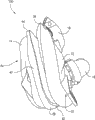
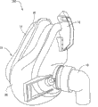
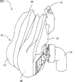
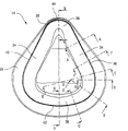
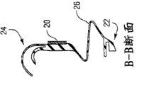
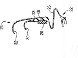
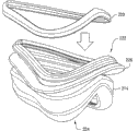
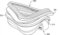
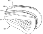
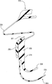
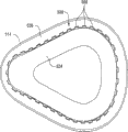
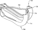
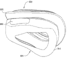
Fig. 1-2 has described a kind of embodiment of patient interface 100, and it is constructed to and can carries breathable gas to the patient.This patient interface 100 comprises framework 12, and can be for good and all or be detachably connected to the liner 14 of this framework 12.Forehead support can movably be connected to the top 16 of framework 12.Head cap assembly (not shown) can be detachably connected to framework 12, so that framework 12 and liner 14 remain on the desired locations of patient's face.Simultaneously, swivel elbow assembly 18 is connected to the front portion of framework 12.These swivel elbow assembly 18 forming and connections connect in the conduit of supercharging supplies.In addition, liner 14 is arranged the according to one embodiment of present invention girth member 20 of structure.Such as following discussion, explosion or lateral expansion when this girth member 20 is constructed to limit liner 14 and in use is subject to high pressure.
In illustrated embodiment, patient interface 100 is full facepiece mask structures, and it is constructed to patient's nose and mouthful conveying breathable gas.Yet patient interface 100 can be nose cup, oronasal mask, mask, nasal tube etc.
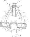
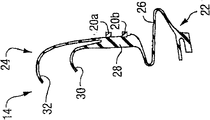
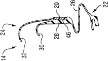
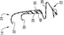
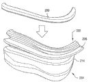
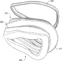
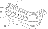
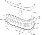
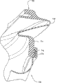
Fig. 3-5 has described another has girth member 20 to connect the embodiment of patient interface 200 thereon, and Fig. 6-8 has described another and has girth member 20 to connect the embodiment of liner 14 thereon.Similar components represents with similar Reference numeral in the drawings.The main distinction of these embodiment is the setting of the gusset portion 26 of liner 14, although should notice that girth member 20 also is applied to not comprise in the face shield of gusset.
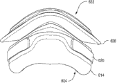
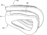
Such as institute's best image among Fig. 9-23, liner 14 comprises: be constructed to as be connected to the non-facial contact section 22 of framework 12 through the slip feather device, be constructed to engage the facial contact section 24 of patient's face, make non-facial contact section 22 and facial contact site 24 interconnected gusset portion 26.As shown in the figure, the preferred facial contact section 24 of liner 14 comprises sidewall 28, the lower liner 30 that extends out from sidewall 28 and the film 32 that provides substantially to cover at least a portion lower liner 30, for example, see that invention Ren Wei Ke Woke (Kwok) etc., the patent No. are 6,112,746 United States Patent (USP), and application number is 10/390,682 U.S. Patent application, each is incorporated herein by reference its full content.
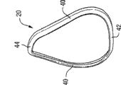
Such as institute's best image among Fig. 9, the facial contact section 24 of liner 14 preferably has basic for the shape of triangle and to be constructed to be contacted with patient's the bridge of the nose, cheek and lower lip regional.Yet facial contact section 24 can have any other suitable shape, as common trapezoidal.In illustrated embodiment, liner 14 comprises: a pair of cheek zone 34 is in order to providing the sealing along cheek and mouthful side, and lower lip zone 36 is in order to providing the sealing to patient's lower lip below, and nasal bridge region 38.
Gusset portion 26 is radially outward with respect to non-facial contact section 22 and facial contact site 24 and extends out, this so that facial contact section 24 can move relative to it.Gusset portion 26 has also improved the sealing effectiveness of liner 14.It is that 10/655,622 U.S. Patent application and application number are that each is incorporated herein by reference its full content in 6,772,760 the United States Patent (USP) that the more details of gusset portion 26 are disclosed in application number.
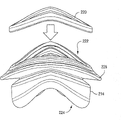
Can be only at the selection area of face gusset portion 26 be set, other parts then do not arrange.Do not need along the whole circumference of liner 14 gusset portion 26 to be set.Similarly, the width of gusset portion 26 can be along the perimeter variations of liner 14.For example, Fig. 1 and 2 has described an embodiment, and wherein the width of gusset portion 26 is substantially constant along the circumference of liner 14, however the embodiment that Fig. 3-5 and Fig. 9 describe, and wherein the width of gusset portion 26 is wider at the selection area of liner 14 such as cheek, lower lip place.
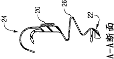
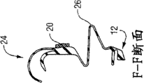
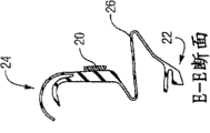
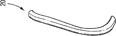
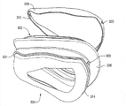
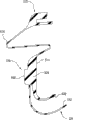
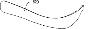
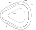
Figure 24-29 has described the embodiment of the independently girth member 20 of pulling down from liner 14.As shown in the figure, girth member 20 have circulus and with the shape of the corresponding as basic triangle of the shape of liner 14.Girth member 20 comprises a pair of cheek zone 40, lower lip zone 42 and nasal bridge region 44.In its operating position, girth member 20 for example, is seen Figure 10-17 along sidewall 28 joint liners 14 between facial contact section 24 and the gusset portion 26.
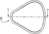
Girth member 20 has the hardness that can optionally change along its length.As shown in Fig. 9-17, the width of girth member 20, the degree of depth or transverse cross-sectional size can be along its length or perimeter variations, with adjust liner 14 the hardness of specific region or elasticity and/or with adapt to liner 14 will be supported the corresponding size of part.That is, girth member 20 can be wider in some zone and can be narrower in some zone.In addition, the wide variety of girth member 20 can be consistent along the wide variety of its circumference with gusset portion 26 and/or sidewall 28.
For example, girth member 20 is narrower in nasal bridge region 44 and lower lip zone 42 (best image in Figure 10,16 and 17), and girth member 20 is wider in cheek zone 40 (best image in Figure 11-15).When being connected to liner 14, girth member 20 is wider at 34 places, cheek zone of liner 14, so that for liner 14 provides larger hardness/reinforcement effect in the zone that this is easier to occur explosion, and girth member 20 is narrower in the nasal bridge region 38 of liner 14 and 36 places, lower lip zone, in order to provide less hardness/reinforcement effect in the zone of this less generation explosion for liner 14.Yet the width of girth member 20 can be in any suitable manner along its perimeter variations.In addition, girth member 20 can have substantially constant width, height or along the section profile of its circumference.
Equally, girth member 20 can suitably be configured to can be used for different embodiment and the patient interface of different size.In addition, girth member 20 can be based on patient's particular requirement and appropriate structuring.For example, the size of girth member 20 can based on the patient specific impression treatment pressure and suitably change.
Figure 18-23 retouches and has shown the various embodiment that girth member 20 are connected to liner 14.For example, Figure 18 has described as utilizing frictional force be connected embodiment on the outer surface of sidewall 28 of liner 14 of a pair of girth member 20a that separates and 20b.Figure 19 has described the embodiment of groove 46 of at least one part that girth member 20 is housed in the outer surface of the sidewall 28 that is positioned at liner 14.Among the embodiment that Figure 20 describes, girth member 20 has stepped cross-section structure in its at least one part, and this girth member 20 is housed in the groove 48 of complementary shape of at least one part of the outer surface of the sidewall 28 that is positioned at liner 14.Among the embodiment that Figure 21 describes, girth member 20 is housed in the groove 46 of at least one part of the inner surface of the sidewall 28 that is positioned at liner 14.Among the embodiment that Figure 22 describes, girth member 20 is connected to the outer surface of the sidewall 28 of liner 14 such as screw by mechanical fastener 50.Among the embodiment that Figure 23 describes, girth member 20 is connected to the outer surface of the sidewall 28 of liner 14 such as glue or ultra-sonic welded or analog by binding agent 52.
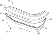
As shown in Figure 28 and 29, girth member 20 can have crooked or arc cross section shape.Liner 14 can have the recess that is suitable for accommodating by interference fit the complementary shape of this crooked girth member 20.
Yet, should be appreciated that girth member 20 can be fastened on the liner 14 with any other appropriate ways.And girth member 20 can come fastening with the combination of above-mentioned connection embodiment.
As shown in Figure 2, girth member 20 can comprise breach 54 in nasal bridge region 44.This breach 54 can be set in order in nasal bridge region 44, obtain more mobility/adaptabilities, or be convenient to girth member 20 is assembled on the liner 14.
In order to understand better advantage of the present invention, defined a coordinate system about patient's face contour.When the patient is straight when being seated, X-axis is level, and Y-axis is vertical, and Z axis stretches into the plane at the facial place of patient.Girth member 20 has increased the hardness of liner 14 on X-Y plane, and the lateral expansion with restriction liner 14 is also referred to as explosion when being subject to high pressure.Girth member 20 has also increased the hardness of liner 14 on the Y-Z plane.That is, girth member 20 has connected top and the bottom of liner 14, this limited the top of liner 14 and bottom towards with away from the motion of patient's face independently moving along Z axis namely.Girth member 20 helps liner to move along Z axis in more consistent mode.Like this, girth member 20 both provided cross-brace also to provide Z axis to support to improve the stability of liner 14.
Equally, girth member 20 can increase the quality of liner 14 valuably, thereby this can improve stability by the variation that allows liner 14 to adapt to lentamente pressure.That is, liner 14 is in use expanded and is left or shrink and approach the patient when facial, and the quality that girth member 20 increases can be slowed down the motion of liner 14.
In an illustrated embodiment, girth member 20 is to separate also being connected thereon of formation with liner 14.Girth member 20 can be made of suitable abundant hard material, such as plastics, synthetic etc.Yet in other embodiments, girth member 20 can be crossed and be cast on the liner 14 to form overall structure.In an example, girth member 20 can be partially submerged into along at least one of the circumference of liner 14.Similarly, girth member 20 also can be made of the silicones pearl that thickens (bead ofsilicone), and it is with liner 14 casting, and its number of patent application that openly is JIUYUE in 2003 submission on the 5th is 10/655, in 622 the U.S. Patent application, be incorporated herein by reference its full content.Usually, girth member 20 is hard with respect to liner 14 under pressure.
In another embodiment, may replace without girth member 20 sidewall 28 to liner 14 adds and increases rib and/or attached buildup thickness.This rib and/or thickness will be carried out the function of the same sidewall that makes liner 14 28 hardening to prevent explosion.In optional embodiment, described rib and/or attached buildup thickness can utilize with girth member 20 combinations.
In another embodiment, for example spring, screw thread or clip device can be incorporated into girth member 20 so that girth member 20 can be adjusted size according to the pressure limit of pad size or its application.
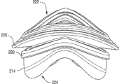
Figure 30-82 has described the optional embodiment of girth member.For example, Figure 30-38 has described another and has been arranged at the embodiment of the girth member 220 (being also referred to as liner top folder is that cushion overclip or saddle overclip are saddle overclip) of liner 214.As shown in the figure, liner 214 comprises non-facial contact section 222, facial contact section 224, and makes non-facial contact section 222 and facial contact site 224 interconnected gusset portion 226.The facial contact section 224 of liner 214 comprises sidewall 228, lower liner 230 and film 232 (seeing Figure 38).
Shown in Figure 30-33, girth member 220 from the top as above non-facial contact section 222, being assembled on the liner 214.Girth member 220 includes the flange 221 (seeing Figure 38) that helps to locate and remain on the liner 214.In its operating position, girth member 220 is along sidewall 228 joint liners 214 between facial contact section 224 and the gusset portion 226, as, see Figure 34-38.Girth member 220 can bonding, mechanically be fixed or cross and cast in the appropriate location.Yet girth member 220 can be for dismountable.
Figure 39-47 has described another and has been arranged at the embodiment of the girth member 320 (being also referred to as liner top folder or saddle overclip) of liner 314.As shown in the figure, liner 314 comprises non-facial contact section 322, facial contact section 324, and makes non-facial contact section 322 and facial contact site 324 interconnected gusset portion 326.The facial contact section 324 of liner 314 comprises sidewall 328, lower liner 330 and film 332 (seeing Figure 47).
Girth member 320 can be from the top as above non-facial contact section 322 or from the bottom as above facial contact section, being assembled to (Figure 39-42 has described from the top assembling) on the liner 314.As shown in the figure, the sidewall 328 of liner 314 comprises the mushroom caput 329 with its integral cast.In illustrated embodiment, provide projection 329 two positions, namely at the opposite end of liner 314.Yet multiple position all is possible.Projection 329 remains on its operating position with girth member 320.
Especially, girth member 320 comprises opening 323, for instance, two openings, the projection 329 that is used for holding is separately passed wherein.Projection 329 can push through and/or be pulled through opening 323 separately in order to girth member 320 is fixed on the appropriate location.Equally, liner 314 comprises and help girth member 320 location of its integral cast and the flange 331 of maintenance.
In its operating position, girth member 320 is along sidewall 328 joint liners 314 between facial contact section 324 and gusset portion 326, as, see Figure 43-47.Girth member 320 also can cast in the appropriate location bonding or excessively.Yet girth member 320 can be for dismountable.
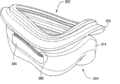
Figure 48-49 has described another and has been arranged at the embodiment of the girth member 420 of liner 414.As shown in the figure, liner 414 comprises non-facial contact section 422, facial contact section 424, and makes non-facial contact section 422 and facial contact site 424 interconnected gusset portion 426.The facial contact section 424 of liner 414 comprises sidewall 428, lower liner 430 and film 432.
In illustrated embodiment, the form of girth member 420 is the reinforcement feature that thickens or the ribs (the silicones pearl that for example thickens) with sidewall 428 integral casts of liner 414.As shown in the figure, liner 414 comprises from the extended rib 420 of the ambient level of liner circumference.Yet the rib 420 of a plurality of levels also is possible.For example, Figure 50 has described the liner 414 of the rib 420 that comprises three levels.
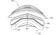
Figure 51-56 has described another and has been arranged at the embodiment of the girth member 520 of liner 514.As shown in the figure, liner 514 comprises non-facial contact section 522, facial contact section 524, and makes non-facial contact section 522 and facial contact site 524 interconnected gusset portion 526.The facial contact section 524 of liner 514 comprises sidewall 528, lower liner 530 and film 532 (seeing Figure 56).
In illustrated embodiment, the form of girth member 520 is a plurality of reinforcement features that thicken or the ribs 560 (the silicones pearl that for example thickens) with sidewall 528 integral casts of liner 514.As shown in the figure, each rib 560 vertically extends.These ribs 560 separate with each other, and extend to limit girth member 520 around the circumference of liner.
As shown in Figure 48-56, be provided with horizontal rib 420 and vertical ribs 560 at the outer surface of liner.Yet, also rib 420,560 can be set at the inner surface of liner.
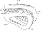
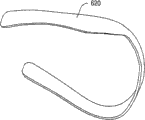
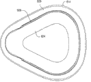
Figure 57-66 has described another and has been arranged at the embodiment of the girth member 620 (being also referred to as liner top folder or saddle overclip) of liner 614.As shown in Figure 62-66, liner 614 comprises non-facial contact section 622, facial contact section 624, and makes non-facial contact section 622 and facial contact site 624 interconnected gusset portion 626.
Among the embodiment as shown in the figure, the form of girth member 620 is part liner top folders, and its selection area to liner 614 provides reinforcement effect.Especially, girth member 620 is roughly U-shaped, and in nasal bridge region otch is arranged, so that in use girth member 620 does not provide support (depending on the gusset type) to the nasal bridge region of liner 614.This configuration prevents that also girth member 620 in use from having influence on the possibility of patient's nose.
In its operating position, girth member 620 is along the partial sidewall joint liner 614 between facial contact section 624 and gusset portion 626, as, see Figure 62-66.Girth member 620 can be bonding, mechanical fasteners or cross and cast in the appropriate location.
Girth member 620 is not limited to the design shown in Figure 57-66.For example, girth member 620 can comprise two or more separation members, and the incision tract that girth member 620 provides can be positioned at other zone.
Similarly, in illustrated embodiment, girth member 620 is positioned at the part outer surface of the sidewall of liner 614, for instance, and in order to prevent overexpansion or explosion.Yet girth member 620 also can be positioned at the inner surface of liner.
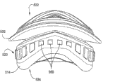
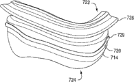
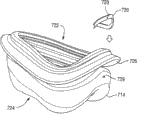
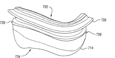
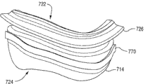
Figure 67-76 has described another and has been arranged at the embodiment of the girth member 720 (being also referred to as liner top folder or saddle overclip) of liner 714.Liner 714 comprises non-facial contact section 722, facial contact section 724, and makes non-facial contact section 722 and facial contact site 724 interconnected gusset portion 726.
Among the embodiment as shown in the figure, girth member 720 is encapsulated in the silicones to be fixed in the liner 714.Especially, at first use substantially hard plastic material that girth member 720 and liner 714 are separated cast (seeing Figure 67).Then, with girth member 720 and liner 714 mechanical engagement, that is to say non-chemically combination.
In one embodiment, hard plastic cushion overclip 720 is inserted in the instrument, and cast on top folder 720 soft silicone cushion 714, i.e. insert molding.
In another embodiment, soft silicone cushion 714 is separated casting with top folder 720, and top folder 720 is manually fitted onto on the liner 714.For example, as shown in Figure 68-71, the sidewall of liner 714 comprises the protrusion 729 with its integral cast.In the embodiment shown, the opposite end at two positions such as liner 714 provides this protrusion 729.Yet multiple position all is possible.Protrusion 729 helps to push up folder 720 and is positioned the appropriate location.Specifically, top folder 720 comprises opening 723, and such as two openings, the protrusion 729 that is used for holding separately passes wherein.
Top folder 720 by mechanically with after liner 714 engages to provide top folder/spacer assembly, second layer silicones 770 casts in partly on the folder/spacer assembly of top with encapsulation or surrounds to push up and presss from both sides 720 (seeing Figure 72-76).That is, second layer silicones 770 is attached on the liner 714 and (is also referred to as the ground floor silicones), but is not joined to top folder 720.This causes top folder 720 to being totally encapsulated or encased in the silicones, thereby does not provide opening can enter by it cavity of folder 720 positions, top by dust or other fragment.
In its operating position, girth member 720 is supported on the liner 714 along the partial sidewall between facial contact section 724 and gusset portion 726, sees Figure 74-76.
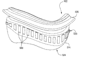
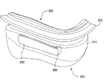
Figure 77-82 has described another and has offered the embodiment of the girth member 820 of liner 814.Liner 814 comprises non-facial contact section 822, facial contact section 824, and makes non-facial contact section 822 and facial contact site 824 interconnected gusset portion 826.
Among the embodiment as shown in the figure, the form of girth member 820 is dismountable rigid plastic inserts 880, and its selection area to liner 814 provides reinforcement effect.Especially, girth member 820 comprise with liner 814 integral casts removably be contained in separately two inserts 880 of recess 890.Yet, also be possible more than two positions.
In its operating position, insert 880 engages with liner 814 along the partial sidewall between facial contact section 824 and gusset portion 826.Insert 880 is positioned at the part outer surface of the sidewall of liner 814, with the hardening assembly of taking on liner/gusset to prevent liner overexpansion or explosion.Yet insert 880 can be positioned at the inner surface of liner 814.
Although the girth member that shown embodiment describes uses jointly with the liner that comprises gusset portion, should be appreciated that girth member can be suitable for using with the liner that does not have gusset portion.
Similarly, although shown embodiment has described girth member and full facepiece mask uses jointly, should be appreciated that, can make girth member be suitable for using with other suitable face shield such as nose cup etc. are common.Especially, very useful when girth member and full facepiece mask use jointly because with nose cup as
Figure G2009102096830D00141
Compare, the gusset portion of full facepiece mask extend in the respiratory cavity ground darker (as, see Figure 10-23).The easier perception explosion of this configuration, thereby and girth member integrate with full facepiece mask and can limit or eliminate this explosion.
Although the present invention is described with most preferred embodiment together with being considered at present the most practical, should be appreciated that to the invention is not restricted to the disclosed embodiments, but on the contrary, should cover various modifications and equivalent arrangements in the spirit and scope of the invention.For example, girth member can be applied to the only selected part in the liner each several part, such as the cheek zone.Similarly, above-mentioned various embodiment can be combined with other embodiment realization, can combine to realize another embodiment with several respects of another embodiment such as several aspects of an embodiment.In addition, although the present invention is applied to suffer the patient of sleep apnea (OSA) especially, suffer the patient of Other diseases (for example congested heart failure, diabetes, morbid obesity, apoplexy, obesity surgery (barriatric surgery)) also can be right benefited from above-mentioned solution.And above-mentioned explanation can be used for patient and the non-patient of non-medical applications equally.

Claims (9)

1. liner that is used for patient interface comprises:
Be suitable for being connected to the non-facial contact section of framework;
Be suitable in use the facial facial contact section that engages with the patient; With
Make the interconnected gusset portion of described non-facial contact section and described facial contact section,
Described facial contact section comprises sidewall and from the extended flexible membrane of described sidewall;
At least a portion of described gusset portion extends radially inwardly from described sidewall and enters the respiratory cavity that is limited by described liner, and
The girth member that exists with the form of a plurality of reinforcement features that thicken or rib, described girth member is arranged at least a portion of the inner surface of described sidewall, and described girth member provides booster action to limit at least the lateral expansion in use of described liner to the sidewall of described liner.
2. liner according to claim 1, wherein said a plurality of reinforcement features that thicken or rib and described sidewall integral cast.
3. liner according to claim 1, wherein said a plurality of reinforcement features that thicken or rib separate with each other.
4. liner according to claim 1, wherein said a plurality of reinforcement features that thicken or rib extend around the liner circumference.
5. liner according to claim 1, wherein said facial contact section be constructed to be bonded on hermetically the patient nose and mouthful around.
6. liner according to claim 1, wherein said a plurality of reinforcement features that thicken or rib are arranged between described facial contact section and the described gusset portion.
7. liner according to claim 1, wherein only the one or more selected part of facial contact section arranges described a plurality of reinforcement feature that thickens or rib.
8. liner according to claim 1, each of wherein said a plurality of reinforcement features that thicken or rib all are suitable for extending along the direction that is approximately perpendicular to patient's facial plane in use.
9. patient interface comprises:
Framework; With
Be arranged on the liner as claimed in claim 1 on the described framework.
CN2009102096830A 2005-01-12 2006-01-12 Reinforcing member for a patient interface Active CN101785894B (en)

Applications Claiming Priority (2)

Application Number Priority Date Filing Date Title
US64312105P 2005-01-12 2005-01-12
US60/643,121 2005-01-12

Related Parent Applications (1)

Application Number Title Priority Date Filing Date
CN200680002203A Division CN100574825C (en) 2005-01-12 2006-01-12 The girth member that is used for patient interface

Publications (2)

Publication Number Publication Date
CN101785894A CN101785894A (en) 2010-07-28
CN101785894B true CN101785894B (en) 2013-09-18

Family

ID=36677305

Family Applications (2)

Application Number Title Priority Date Filing Date
CN2009102096830A Active CN101785894B (en) 2005-01-12 2006-01-12 Reinforcing member for a patient interface
CN200680002203A Active CN100574825C (en) 2005-01-12 2006-01-12 The girth member that is used for patient interface

Family Applications After (1)

Application Number Title Priority Date Filing Date
CN200680002203A Active CN100574825C (en) 2005-01-12 2006-01-12 The girth member that is used for patient interface

Country Status (7)

Country Link
US (3) US8261746B2 (en)
EP (2) EP3103499B1 (en)
JP (1) JP5160236B2 (en)
CN (2) CN101785894B (en)
AU (1) AU2006206041A1 (en)
NZ (1) NZ556251A (en)
WO (1) WO2006074514A1 (en)

Families Citing this family (97)

* Cited by examiner, † Cited by third party
Publication number Priority date Publication date Assignee Title
US7057256B2 (en) 2001-05-25 2006-06-06 President & Fellows Of Harvard College Silicon-based visible and near-infrared optoelectric devices
US7442629B2 (en) 2004-09-24 2008-10-28 President & Fellows Of Harvard College Femtosecond laser-induced formation of submicrometer spikes on a semiconductor substrate
ES2459216T3 (en) 2003-05-02 2014-05-08 Resmed Limited Mask system
ES2381478T3 (en) 2003-12-08 2012-05-28 Fisher & Paykel Healthcare Limited Respiratory aid
WO2005079726A1 (en) 2004-02-23 2005-09-01 Fisher & Paykel Healthcare Limited Breathing assistance apparatus
EP1737524B1 (en) 2004-04-02 2018-10-10 Fisher & Paykel Healthcare Limited Breathing assistance apparatus
US9072852B2 (en) 2004-04-02 2015-07-07 Fisher & Paykel Healthcare Limited Breathing assistance apparatus
EP3103499B1 (en) * 2005-01-12 2020-05-20 ResMed Pty Ltd Reinforcing member for a patient interface
DE202006021258U1 (en) 2005-01-12 2014-05-05 Resmed Limited Upholstery for patient interface
US20090151729A1 (en) 2005-11-08 2009-06-18 Resmed Limited Nasal Assembly
US7762258B2 (en) * 2005-12-02 2010-07-27 Carefusion 2200, Inc. Infant nasal interface mask
EP2029208B1 (en) * 2006-06-16 2020-02-26 Fisher & Paykel Healthcare Limited Breathing assistance apparatus and method of forming an outer sealing member
CN102631741B (en) 2006-07-14 2015-11-04 菲舍尔和佩克尔保健有限公司 Respiratory assist system
WO2008058330A1 (en) 2006-11-14 2008-05-22 Resmed Ltd Frame and vent assembly for mask assembly
JP4945432B2 (en) 2006-12-28 2012-06-06 富士フイルム株式会社 Preparation method of lithographic printing plate
NZ578334A (en) * 2007-04-19 2011-01-28 Resmed Ltd Mask frame connected to face cushion via intervening clip
DE202009018972U1 (en) * 2008-03-04 2014-12-09 Resmed Limited mask system
US11331447B2 (en) 2008-03-04 2022-05-17 ResMed Pty Ltd Mask system with snap-fit shroud
AU2014100361A4 (en) * 2008-03-04 2014-05-08 Resmed Limited Mask System
US8066738B2 (en) * 2008-03-31 2011-11-29 Playtex Products, Inc. Pacifier
US10792451B2 (en) 2008-05-12 2020-10-06 Fisher & Paykel Healthcare Limited Patient interface and aspects thereof
US10258757B2 (en) 2008-05-12 2019-04-16 Fisher & Paykel Healthcare Limited Patient interface and aspects thereof
US11660413B2 (en) 2008-07-18 2023-05-30 Fisher & Paykel Healthcare Limited Breathing assistance apparatus
EP2145645B1 (en) * 2008-07-18 2012-01-04 Fisher & Paykel Healthcare Limited Breathing assistance apparatus
EP2349428B1 (en) 2008-10-10 2017-09-20 Fisher & Paykel Healthcare Limited Nasal pillows for a patient interface
AU2009327642B2 (en) 2008-12-17 2015-08-20 Fisher & Paykel Healthcare Limited Respiratory mask sealing interface
US9911781B2 (en) 2009-09-17 2018-03-06 Sionyx, Llc Photosensitive imaging devices and associated methods
US9673243B2 (en) 2009-09-17 2017-06-06 Sionyx, Llc Photosensitive imaging devices and associated methods
EP2501423A4 (en) 2009-11-18 2014-10-29 Fisher & Paykel Healthcare Ltd Nasal interface
CN105771053B (en) * 2009-11-20 2020-03-13 瑞思迈私人有限公司 Mask system
US8692198B2 (en) 2010-04-21 2014-04-08 Sionyx, Inc. Photosensitive imaging devices and associated methods
US20120146172A1 (en) 2010-06-18 2012-06-14 Sionyx, Inc. High Speed Photosensitive Devices and Associated Methods
WO2012047121A1 (en) 2010-10-08 2012-04-12 Fisher & Paykel Healthcare Limited Breathing assistance apparatus
US10603456B2 (en) 2011-04-15 2020-03-31 Fisher & Paykel Healthcare Limited Interface comprising a nasal sealing portion
EP4282456A3 (en) 2011-04-15 2024-02-14 Fisher & Paykel Healthcare Limited Interface comprising a rolling nasal bridge portion
US9496308B2 (en) 2011-06-09 2016-11-15 Sionyx, Llc Process module for increasing the response of backside illuminated photosensitive imagers and associated methods
CN107469208B (en) * 2011-07-01 2020-07-07 费雪派克医疗保健有限公司 Nasal mask interface assembly
EP3718586B1 (en) * 2011-07-12 2023-11-29 ResMed Pty Ltd Textile mask systems
CN103946867A (en) 2011-07-13 2014-07-23 西奥尼克斯公司 Biometric imaging devices and associated methods
EP2747820A1 (en) * 2011-10-26 2014-07-02 Koninklijke Philips N.V. Cushion for patient interface with localized region of reduced stiffness
WO2013098727A2 (en) * 2011-12-27 2013-07-04 Koninklijke Philips Electronics N.V. Patient interface, cushion thereof, and manufacturing method
US9064764B2 (en) 2012-03-22 2015-06-23 Sionyx, Inc. Pixel isolation elements, devices, and associated methods
RU2641836C2 (en) 2012-05-16 2018-01-22 Конинклейке Филипс Н.В. Patient interface devices
US9907924B2 (en) 2012-06-12 2018-03-06 Koninklijke Philips N.V. Sealing cushion having corrugated sealing flap
US10232135B2 (en) 2012-08-03 2019-03-19 Fisher & Paykel Healthcare Limited Deformable insert for low pressure patient interface
CN107626023B (en) 2012-08-08 2021-03-02 费雪派克医疗保健有限公司 Interface assembly for use in providing respiratory therapy
EP4279106A3 (en) 2012-09-04 2024-01-17 Fisher & Paykel Healthcare Limited Valsalva mask
DE112013005483T5 (en) 2012-11-16 2015-08-13 Fisher & Paykel Healthcare Limited Nose gasket and ventilation interface
US10449316B2 (en) * 2012-12-13 2019-10-22 Koninklijke Philips N.V. Mask with red mark alleviating pocket
WO2017049361A1 (en) * 2015-09-23 2017-03-30 Resmed Limited Patient interface with a seal-forming structure having varying thickness
WO2014127376A2 (en) 2013-02-15 2014-08-21 Sionyx, Inc. High dynamic range cmos image sensor having anti-blooming properties and associated methods
WO2014151093A1 (en) 2013-03-15 2014-09-25 Sionyx, Inc. Three dimensional imaging utilizing stacked imager devices and associated methods
US9209345B2 (en) 2013-06-29 2015-12-08 Sionyx, Inc. Shallow trench textured regions and associated methods
CN105358204B (en) 2013-07-17 2018-01-19 费雪派克医疗保健有限公司 Patient interface and its many aspects
AU2014305231B2 (en) 2013-08-05 2019-04-18 Fisher & Paykel Healthcare Limited Seal for a patient interface, interface assemblies and aspects thereof
GB201314885D0 (en) * 2013-08-20 2013-10-02 3M Innovative Properties Co Personal respiratory protection device
GB201314884D0 (en) * 2013-08-20 2013-10-02 3M Innovative Properties Co Personal respiratory protection device
GB201314886D0 (en) * 2013-08-20 2013-10-02 3M Innovative Properties Co Personal respiratory protection device
USD787659S1 (en) * 2013-09-24 2017-05-23 3M Innovative Properties Company Respirator with face seal flexing region
USD740932S1 (en) * 2013-09-24 2015-10-13 3M Innovative Properties Company Respirator with raised face seal flexing region
ITPG20130052A1 (en) * 2013-11-12 2015-05-13 3A Health Care S R L MASK FOR THE ADMINISTRATION OF AN ATOMIZED MIXTURE
GB2521644B (en) 2013-12-24 2020-03-11 Intersurgical Ag Improvements relating to respiratory masks
CN103816600A (en) * 2014-03-14 2014-05-28 宁波圣宇瑞医疗器械有限公司 Medical mask
CN103830820A (en) * 2014-03-14 2014-06-04 宁波圣宇瑞医疗器械有限公司 Medical face mask and face mask assembly
WO2015142191A1 (en) 2014-03-18 2015-09-24 Fisher & Paykel Healthcare Limited Gel resuscitation mask
MX2016015858A (en) 2014-06-04 2017-06-28 Revolutionary Medical Devices Inc Combined nasal and mouth ventilation mask.
CN110876827B (en) 2014-06-17 2022-08-02 费雪派克医疗保健有限公司 Patient interface
US20150374943A1 (en) * 2014-06-30 2015-12-31 Alex Alexani Flexible cushion system for oxygen mask
EP3169390B1 (en) * 2014-07-16 2019-11-27 Breas Medical, Inc. Facial interface and headgear system for use with ventilation and positive air pressure systems
CN111921054B (en) 2014-08-20 2023-09-08 革新医疗器械有限公司 Ventilation mask
GB2587295B8 (en) 2014-08-25 2021-09-29 Fisher & Paykel Healthcare Ltd Respiratory mask and related portions, components or sub-assemblies
USD825740S1 (en) 2014-12-12 2018-08-14 Revolutionary Medical Devices Surgical mask
US11097077B2 (en) * 2015-03-27 2021-08-24 Fisher & Paykel Healthcare Limited Patient interface and aspects thereof
WO2016201358A1 (en) 2015-06-11 2016-12-15 Revolutionary Medical Devices, Inc. Ventilation mask
US10994090B2 (en) 2015-09-04 2021-05-04 Fisher & Paykel Healthcare Limited Patient interfaces
CN105413035A (en) * 2015-12-24 2016-03-23 北京怡和嘉业医疗科技有限公司 Liner for breathing mask and breathing mask
CN105935465B (en) * 2016-04-13 2018-09-25 浙江富胜达科技有限公司 Exempt from button the mask
USD882066S1 (en) 2016-05-13 2020-04-21 Fisher & Paykel Healthcare Limited Frame for a breathing mask
CN106267489B (en) * 2016-08-25 2018-10-16 深圳瑞之谷医疗科技有限公司 Flexible case and respiratory interface device
BR112019004967A8 (en) 2016-09-14 2023-03-21 Revolutionary Medical Devices Inc VENTILATION MASK
US9629975B1 (en) 2016-09-14 2017-04-25 Revolutionary Medical Devices, Inc. Ventilation mask
CN114904112A (en) 2016-10-05 2022-08-16 费雪派克医疗保健有限公司 Patient interface
USD848606S1 (en) 2016-11-07 2019-05-14 Revolutionary Medical Devices, Inc. Surgical mask
USD823455S1 (en) 2017-02-23 2018-07-17 Fisher & Paykel Healthcare Limited Cushion assembly for breathing mask assembly
USD824020S1 (en) 2017-02-23 2018-07-24 Fisher & Paykel Healthcare Limited Cushion assembly for breathing mask assembly
USD823454S1 (en) 2017-02-23 2018-07-17 Fisher & Paykel Healthcare Limited Cushion assembly for breathing mask assembly
USD901673S1 (en) 2017-03-09 2020-11-10 Fisher & Paykel Healthcare Limited Frame and breathing tube assembly for a nasal mask
USD874646S1 (en) 2017-03-09 2020-02-04 Fisher & Paykel Healthcare Limited Headgear component for a nasal mask assembly
USD875242S1 (en) 2017-09-20 2020-02-11 Fisher & Paykel Healthcare Limited Nasal mask and breathing tube set
USD855793S1 (en) 2017-09-20 2019-08-06 Fisher & Paykel Healthcare Limited Frame for a nasal mask
USD898188S1 (en) 2017-11-17 2020-10-06 Revolutionary Medical Devices, Inc. Surgical mask
USD884153S1 (en) 2018-04-04 2020-05-12 Fisher & Paykel Healthcare Limited Frame for a mask assembly
CN109646779A (en) * 2018-12-29 2019-04-19 北京怡和嘉业医疗科技股份有限公司 Liner, breathing mask and the ventilation therapy equipment of breathing mask
WO2020165761A1 (en) 2019-02-13 2020-08-20 ResMed Pty Ltd Textile seal with air-assisted biasing portion
WO2020229939A1 (en) * 2019-05-10 2020-11-19 3M Innovative Properties Company Facepiece chin retention feature
WO2021046593A1 (en) * 2019-09-10 2021-03-18 ResMed Pty Ltd Patient interface
WO2023144717A1 (en) * 2022-01-25 2023-08-03 Tallon Eric Continuous positive pressure ventilation mask

Citations (1)

* Cited by examiner, † Cited by third party
Publication number Priority date Publication date Assignee Title
US6729333B2 (en) * 1999-05-12 2004-05-04 Respironics, Inc. Low contact nasal mask and system using same

Family Cites Families (22)

* Cited by examiner, † Cited by third party
Publication number Priority date Publication date Assignee Title
US4907584A (en) 1988-03-03 1990-03-13 Mcginnis Gerald E Respiratory mask
US5074297A (en) * 1989-12-19 1991-12-24 The General Hospital Corporation Self-sealing mask for delivering intermittent positive pressure ventilation
DE4138172C2 (en) 1991-11-21 1994-06-09 Draegerwerk Ag Half mask
US5647357A (en) * 1995-09-08 1997-07-15 Respironics, Inc. Respiratory mask facial seal
AUPO126596A0 (en) 1996-07-26 1996-08-22 Resmed Limited A nasal mask and mask cushion therefor
US6513526B2 (en) * 1996-07-26 2003-02-04 Resmed Limited Full-face mask and mask cushion therefor
US5746201A (en) 1997-01-23 1998-05-05 Nellcor Puritan-Bennett CPAP nose mask
AU137823S (en) * 1998-12-09 1999-07-20 Resmed Ltd Mask cushion
US6467483B1 (en) * 1999-07-28 2002-10-22 Respironics, Inc. Respiratory mask
EP1118346A3 (en) 2000-01-21 2003-06-18 MPV-Truma Gesellschaft Für Medizintechnische Produkte mbH Nasal breathing mask and mask cushion for a nasal breathing mask
AU2000234250A1 (en) 2000-02-25 2001-09-03 Map Medizintechnik Fur Arzt Und Patient Gmbh And Co. Kg Sealing lip device for a respiratory mask, respiratory mask and a method and a mould for producing the same
AU2001267947B2 (en) * 2000-06-14 2004-01-15 Fisher & Paykel Healthcare Limited Breathing assistance apparatus
US6986352B2 (en) * 2000-06-22 2006-01-17 Resmed Limited Mask with gusset
US7007696B2 (en) * 2001-05-18 2006-03-07 Tiara Medical Systems, Inc. Mask cushion and method of using same
DE60225895T2 (en) * 2001-09-07 2009-04-09 ResMed Ltd., Bella Vista mask assembly
US8997742B2 (en) 2002-04-23 2015-04-07 Resmed Limited Ergonomic and adjustable respiratory mask assembly with cushion
WO2003105921A2 (en) 2002-06-14 2003-12-24 Map Medizin-Technologie Gmbh Mask cushioning and forehead pad for a respiratory mask, respiratory mask in addition to a mould and method for their production
EP2913079B1 (en) * 2002-09-06 2017-10-25 ResMed Limited Cushion for respiratory mask assembly
ES2381478T3 (en) 2003-12-08 2012-05-28 Fisher & Paykel Healthcare Limited Respiratory aid
EP1737524B1 (en) * 2004-04-02 2018-10-10 Fisher & Paykel Healthcare Limited Breathing assistance apparatus
US7353827B2 (en) * 2004-09-01 2008-04-08 Vitol Signs, Inc. Mask, mask shell and seal with improved mounting, mask seal, method of mask manufacture and mask with reduced exhalation noise
EP3103499B1 (en) * 2005-01-12 2020-05-20 ResMed Pty Ltd Reinforcing member for a patient interface

Patent Citations (1)

* Cited by examiner, † Cited by third party
Publication number Priority date Publication date Assignee Title
US6729333B2 (en) * 1999-05-12 2004-05-04 Respironics, Inc. Low contact nasal mask and system using same

Also Published As

Publication number Publication date
US8261746B2 (en) 2012-09-11
NZ556251A (en) 2010-05-28
EP3103499A1 (en) 2016-12-14
US20140041664A1 (en) 2014-02-13
EP1841482A1 (en) 2007-10-10
CN100574825C (en) 2009-12-30
JP5160236B2 (en) 2013-03-13
EP1841482B1 (en) 2016-07-06
JP2008526392A (en) 2008-07-24
EP3103499B1 (en) 2020-05-20
EP1841482A4 (en) 2009-11-11
CN101785894A (en) 2010-07-28
CN101119763A (en) 2008-02-06
US8573212B2 (en) 2013-11-05
WO2006074514A1 (en) 2006-07-20
AU2006206041A1 (en) 2006-07-20
US20090000623A1 (en) 2009-01-01
US20120312304A1 (en) 2012-12-13

Similar Documents

Publication Publication Date Title
CN101785894B (en) Reinforcing member for a patient interface
JP7178952B2 (en) Cushion for patient interface
US10850057B2 (en) Cushion for a respiratory mask assembly
JP6063973B2 (en) Mask system
JP6360485B2 (en) Interface with nasal seal and rolling hinge
US7975694B2 (en) Non-intrusive mask interface with nasal support
JP5906240B2 (en) Patient interface device with dynamic self-adjusting mechanism
EP1755719B1 (en) Cushion for a patient interface
JP2015532169A5 (en)
US20150157824A1 (en) Cushion with compression control

Legal Events

Date Code Title Description
C06 Publication
PB01 Publication
C10 Entry into substantive examination
SE01 Entry into force of request for substantive examination
C14 Grant of patent or utility model
GR01 Patent grant
C56 Change in the name or address of the patentee

Owner name: RESMED LIMITED

Free format text: FORMER NAME: RAYSMEDD CO., LTD.

CP01 Change in the name or title of a patent holder

Address after: New South Wales, Australia

Patentee after: RESMED LTD.

Address before: New South Wales, Australia

Patentee before: Raysmedd Co., Ltd.

CP01 Change in the name or title of a patent holder

Address after: New South Wales, Australia

Patentee after: Reisman Private Limited

Address before: New South Wales, Australia

Patentee before: RESMED LTD.