CN101811397B - Image stitching method and device for a multi-head printer - Google Patents
Image stitching method and device for a multi-head printer Download PDFInfo
- Publication number
- CN101811397B CN101811397B CN2009101704665A CN200910170466A CN101811397B CN 101811397 B CN101811397 B CN 101811397B CN 2009101704665 A CN2009101704665 A CN 2009101704665A CN 200910170466 A CN200910170466 A CN 200910170466A CN 101811397 B CN101811397 B CN 101811397B
- Authority
- CN
- China
- Prior art keywords
- printhead
- density
- printer
- pattern
- zone
- Prior art date
- Legal status (The legal status is an assumption and is not a legal conclusion. Google has not performed a legal analysis and makes no representation as to the accuracy of the status listed.)
- Expired - Fee Related
Links
- 238000000034 method Methods 0.000 title claims abstract description 35
- 238000012886 linear function Methods 0.000 claims abstract description 11
- 238000009958 sewing Methods 0.000 claims description 8
- 238000007639 printing Methods 0.000 abstract description 44
- 238000012216 screening Methods 0.000 abstract 2
- 230000006870 function Effects 0.000 description 20
- 230000007704 transition Effects 0.000 description 11
- 210000001503 joint Anatomy 0.000 description 10
- 230000008859 change Effects 0.000 description 9
- 238000005516 engineering process Methods 0.000 description 9
- 230000000694 effects Effects 0.000 description 7
- 238000004590 computer program Methods 0.000 description 5
- 230000014509 gene expression Effects 0.000 description 5
- 230000003252 repetitive effect Effects 0.000 description 5
- 230000002950 deficient Effects 0.000 description 4
- 230000004044 response Effects 0.000 description 4
- 238000003860 storage Methods 0.000 description 4
- 239000000976 ink Substances 0.000 description 3
- 230000010363 phase shift Effects 0.000 description 3
- 239000000049 pigment Substances 0.000 description 3
- 238000000926 separation method Methods 0.000 description 3
- 230000008901 benefit Effects 0.000 description 2
- 238000010586 diagram Methods 0.000 description 2
- 238000010438 heat treatment Methods 0.000 description 2
- 239000003550 marker Substances 0.000 description 2
- 238000012546 transfer Methods 0.000 description 2
- 108091081062 Repeated sequence (DNA) Proteins 0.000 description 1
- 230000005540 biological transmission Effects 0.000 description 1
- 244000309464 bull Species 0.000 description 1
- 238000004364 calculation method Methods 0.000 description 1
- 239000003086 colorant Substances 0.000 description 1
- 238000004040 coloring Methods 0.000 description 1
- 238000012937 correction Methods 0.000 description 1
- 238000005336 cracking Methods 0.000 description 1
- 230000007547 defect Effects 0.000 description 1
- 238000013461 design Methods 0.000 description 1
- 238000009792 diffusion process Methods 0.000 description 1
- 230000002349 favourable effect Effects 0.000 description 1
- 230000006872 improvement Effects 0.000 description 1
- 238000005304 joining Methods 0.000 description 1
- 239000000463 material Substances 0.000 description 1
- 239000011159 matrix material Substances 0.000 description 1
- 230000007246 mechanism Effects 0.000 description 1
- 230000004048 modification Effects 0.000 description 1
- 238000012986 modification Methods 0.000 description 1
- 230000006855 networking Effects 0.000 description 1
- 238000005457 optimization Methods 0.000 description 1
- 238000000819 phase cycle Methods 0.000 description 1
- 230000008569 process Effects 0.000 description 1
- 239000004065 semiconductor Substances 0.000 description 1
- 230000035807 sensation Effects 0.000 description 1
- 239000000126 substance Substances 0.000 description 1
- 238000010023 transfer printing Methods 0.000 description 1
Images


Classifications
-
- B—PERFORMING OPERATIONS; TRANSPORTING
- B41—PRINTING; LINING MACHINES; TYPEWRITERS; STAMPS
- B41J—TYPEWRITERS; SELECTIVE PRINTING MECHANISMS, i.e. MECHANISMS PRINTING OTHERWISE THAN FROM A FORME; CORRECTION OF TYPOGRAPHICAL ERRORS
- B41J2/00—Typewriters or selective printing mechanisms characterised by the printing or marking process for which they are designed
- B41J2/485—Typewriters or selective printing mechanisms characterised by the printing or marking process for which they are designed characterised by the process of building-up characters or image elements applicable to two or more kinds of printing or marking processes
- B41J2/505—Typewriters or selective printing mechanisms characterised by the printing or marking process for which they are designed characterised by the process of building-up characters or image elements applicable to two or more kinds of printing or marking processes from an assembly of identical printing elements
- B41J2/5056—Typewriters or selective printing mechanisms characterised by the printing or marking process for which they are designed characterised by the process of building-up characters or image elements applicable to two or more kinds of printing or marking processes from an assembly of identical printing elements using dot arrays providing selective dot disposition modes, e.g. different dot densities for high speed and high-quality printing, array line selections for multi-pass printing, or dot shifts for character inclination
-
- B—PERFORMING OPERATIONS; TRANSPORTING
- B41—PRINTING; LINING MACHINES; TYPEWRITERS; STAMPS
- B41J—TYPEWRITERS; SELECTIVE PRINTING MECHANISMS, i.e. MECHANISMS PRINTING OTHERWISE THAN FROM A FORME; CORRECTION OF TYPOGRAPHICAL ERRORS
- B41J2/00—Typewriters or selective printing mechanisms characterised by the printing or marking process for which they are designed
- B41J2/315—Typewriters or selective printing mechanisms characterised by the printing or marking process for which they are designed characterised by selective application of heat to a heat sensitive printing or impression-transfer material
- B41J2/32—Typewriters or selective printing mechanisms characterised by the printing or marking process for which they are designed characterised by selective application of heat to a heat sensitive printing or impression-transfer material using thermal heads
- B41J2/35—Typewriters or selective printing mechanisms characterised by the printing or marking process for which they are designed characterised by selective application of heat to a heat sensitive printing or impression-transfer material using thermal heads providing current or voltage to the thermal head
- B41J2/355—Control circuits for heating-element selection
-
- H—ELECTRICITY
- H04—ELECTRIC COMMUNICATION TECHNIQUE
- H04N—PICTORIAL COMMUNICATION, e.g. TELEVISION
- H04N1/00—Scanning, transmission or reproduction of documents or the like, e.g. facsimile transmission; Details thereof
- H04N1/387—Composing, repositioning or otherwise geometrically modifying originals
- H04N1/3876—Recombination of partial images to recreate the original image
Abstract
Techniques are disclosed for stitching images printed by a multi-head printer in a manner that is relatively insensitive to misregistration of the image segments. When a pair of overlapping print heads print a pair of adjacent image segments which meet in a stitching region (608), printing at each location in the stitching region (608) is accomplished by both print heads with a weighting (614, 624) that depends on the location being printed within the stitching region. In one embodiment, for example, the output (634, 644) of each print head is weighted by a linear function of horizontal pixel position. Techniques are also disclosed for selecting screening patterns for use when stitching is performed with variable-dot printers. Such screening patterns are selected to minimize variations indensity that may arise as the result of cross-web and/or down-web misregistration.
Description
The application is the dividing an application of PCT application that got into the China national stage on August 22nd, 2005, and the applying date of this PCT application is on February 19th, 2004, and application number is PCT/US2004/004873.Getting into the national applications of China national after the stage number is 200480004790.5, and denomination of invention is " image stitching of multi-head printer ".
Technical field
The present invention relates to the bull thermal printer, specifically, relate to the thermal printer that uses a plurality of printheads and print single image with the form of a plurality of linkage sections.
Background technology
Calculating and the digital picture field, various printers are well-known.Such printer comprises such as dot-matrix printer, laser printer, ink-jet printer and thermal printer.The focus of this discussion is a thermal printer, and so name is because they use heat energy (heat) to produce printout.More particularly; Thermal printer generally comprises the linear array of heating element heater (being also referred to as " printing head component " at this), and it is through for example shifting pigment or form reaction and print at output medium in output medium starting color to output medium from granting paper (donor sheet).Output medium generally is the recipient who is good at accepting the porous of the pigment that shifted, or applied the paper that color forms chemical substance.When triggering, each printing head component forms color on the medium below this printhead, produces the spot that specific density is arranged.Has the more black sensation in zone of giving than have less or less density spot greatly or than the zone of dense patch point.Digital picture shows as by two-dimensional array very little and that the very near spot of being separated by forms.
The thermal printer head element starts through being provided energy.To the temperature that printing head component provides energy to increase printing head component, cause to the pigment transfer of output medium or the color in the receiver to form.Like this, the quantity by printing head component output density that produces and the energy of supplying with printing head component has substantial connection.Through for example changing the delivery of in specified time interval, giving printing head component or supplying power for printing head component for more time, can change the energy of supplying with printing head component.
Single thermal printer can comprise a plurality of thermal printer heads, and they can be for example interlaced.In the United States Patent (USP) 4660052 of authorizing people such as Kaiya, described a routine this printer, it is along the be staggered heat sensitive recording apparatus of a plurality of thermal printer heads of two roller platens.This device has the image segments of on first roller platen, being printed through first group of printhead that replaces.On second roller platen, fill intervenient section through second group of printhead prints.Arrange this so that the printing crossover of the printing of second group of printhead and first group of printhead forms " stitching " zone between each section to adjacency, wherein the scalable printing makes from the transition to another not obvious.In this patent, " joiner " (joinery) method is described to simple butt joint joint, wherein near the center of each suture zone, selects transition point.By those all pixels to the printhead prints transition point left side, left side of crossover head, and by those all pixels to printhead prints transition point the right, right side of crossover head.The problem that this " joiner " method exists is that the defective in the printer hardware lacks robustness.For example, if the motion of paper not exclusively perpendicular to printhead, so when from one group of printhead to another group printhead when moving paper can move to the left side or the right slightly, thereby in stitching, crack or cause the crossover of image segments.Except that these mechanical defectives, thermal printer head can generate heat when printing, and made the printhead thermal expansion and caused visible image segments crossover.
Authorize the United States Patent (USP) 4997410 of Onuki and Denda and described the concrete device that is used to realize aforesaid butt joint joint, it assigns the suture zone data for suitable printhead, and this depends on that they are the right or the left side at selected transition point.This patent has been described the artificial means of adjustment has again been carried out in stitching, eliminating any visible slit or crossover, and has described the means that are used for compensating automatically the printhead thermal expansion influence.Best, correct operation does not need such manual work adjustment.
Authorize the United States Patent (USP) 5119108 of Hatakeyama and described a similar system of ten minutes, but the saving grace that it increased is 2-4 pixel of image segments crossover, thereby (to all practical purposes) eliminated the possibility of between image segments, cracking.This has just introduced the higher print density in the wide zone of 2-4 pixel certainly, because the crossover width is very narrow, the inventor obviously not thinks can cause opposition.Yet this defective extends to whole length of image, and perhaps is visible, narrow width that let it be to the greatest extent.
Solution to this problem has been proposed in the United States Patent (USP) of authorizing Stephenson and Fiscella 5450099.The joining ratio that this patent is described simply docks joint and will come complicatedly.On each line of suture zone, the pixel that random division will be printed between two printheads.In stitching, half of the about print pixel of each printhead printed so that by one in two printheads or another each pixel of printing across.On each line, the random division that changes pixel is not so that exist the pattern of reproduction from the line to the line.This has been avoided extending the disadvantages associated of whole length of image, still, it really the machinery and the thermal capacitance limit of printer requirement has been proposed because the misregistration of pattern will cause the great uncontrollable variation of print density of suture zone.Under the situation of misregistration, two printheads will be printed about 25% pixel, and 25% pixel will can be by any one printhead prints.The increase of the density that these occur at random can not compensate with minimizing each other, so printed incomplete density.
U.S. Pat 6385349A discloses the coincidence district at adjacent area, adjusts color of image through brightness, contrast, the gamma parameter of print data being said line function optimization, improves print quality.
Consider these shortcomings of the image segments stitching of thermal printer in the art methods; The thermal expansion of mechanical defect in the printer hardware and printer unit needs the method that engages image segments, so that can not cause occurring on the print image visible artificial vestige.As a result, such method will make the improvement of picture quality, and the thermal printer cost of wide format reduced (owing to not needing high-precision transport sector).
Summary of the invention
The invention discloses a kind of in multi-head printer, be used for the sewing up first area of digital picture and the method for second area, said method comprising the steps of:
(A) identification comprises the suture zone of the adjacent part of first area and second area;
(B) through carrying out following steps, use first printhead of said multi-head printer and the adjacent part that second printhead is printed said first area and second area:
(1) with the output of first weighting function said first printhead of weighting in said suture zone; And
(2) with the output of second weighting function said second printhead of weighting in said suture zone;
Wherein, said first weighting function comprises the linear function with slope s, and said second weighting function comprises the linear function with slope-s.
The invention also discloses 5. 1 kinds and in multi-head printer, sew up the first area of digital picture and the device of second area, said device comprises:
Discern the parts of the suture zone of the adjacent part that comprises said first area and said second area;
With the parts that first printhead and second printhead of said multi-head printer are printed the adjacent part of said first area and said second area, the said parts that are used to print comprise:
Parts with the output of said first printhead of weighting in said suture zone of first weighting function; And
Parts with the output of said second printhead of weighting in said suture zone of second weighting function;
Wherein, said first weighting function comprises the linear function with slope s, and said second weighting function comprises the linear function with slope-s.
Disclosed technology is used for sewing up by multi-head printer, with the mode images printed to the misregistration relative insensitivity of image segments.During the image segments of a pair of vicinity of meeting in the suture zone when the printhead prints of a pair of crossover, accomplish the printing in each position, suture zone by two printheads with weighting scheme, the print position in the suture zone is depended in said weighting.For example, in one embodiment, come the output of each printhead of weighting with the linear function of a horizontal pixel location.The technology that the selection of when sewing up with the variable-dot printer, using supplies the site pattern of use is also disclosed.Select such site pattern to reduce to minimum will result from the variable density that the horizontal and/or downward misregistration of roll web causes.
Following explanation and claim scope are with illustrating other characteristics and the advantage that various form of the present invention and embodiment are had.
Description of drawings
Figure 1A is the sketch map of image-region, wherein prints two sub regions with the butt joint joint of prior art by multi-head printer, and this two sub regions is just in time met at the center of suture zone;
Figure 1B is the sketch map of image-region, wherein, prints two sub regions with the butt joint joint of prior art by multi-head printer, and causes two sub regions part crossover in the suture zone because of horizontal aligument is bad;
Fig. 2 is the curve map of explanation relation between location of pixels and the density in the image-region shown in Figure 1A;
Fig. 3 is the curve map of explanation relation between location of pixels and the density in the image-region shown in Figure 1B;
Fig. 4 is weighting function and the curve map of total output density that the result obtains when do not have aiming at bad generation of the printhead that adds to crossover of explanation one embodiment of the invention;
Fig. 5 is weighting function and the curve map of total output density of obtaining as horizontal aligument result of bad when generation of the printhead that adds to crossover of explanation one embodiment of the invention;
Fig. 6 A-6F is the curve map that explanation is applied to various embodiments of the present invention the non-uniform image data;
The stipple pattern that Fig. 7 A-7B explanation pane is arranged;
The stipple pattern of Fig. 7 C explanation Fig. 7 A-7B of crossover with cover point (dot-on-dot) layout;
The stipple pattern of Fig. 7 D explanation Fig. 7 A-7B of crossover with a dot interlace (dot-off-dot) layout;
The stipple pattern of Fig. 8 A explanation interlaced arrangement;
The stipple pattern of Fig. 8 B explanation rectangular arrangement;
The stipple pattern of the mutual crossover of Fig. 8 C key diagram 8A-8B;
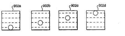
Fig. 9 A explains four routine pixels, and wherein each example is included in a distinct site in the position, four sites;
The pattern that Fig. 9 B explanation is repeated to form by the pattern of four pixels shown in Fig. 9 A;
Three four pattern of pixels that can be used for the siteization of Fig. 9 C-9E explanation various embodiments of the present invention;
Figure 10 explains the stack of two four different pattern of pixels;
The stack that Figure 11 explanation has two bad three different pattern of pixels of perpendicular alignmnet; And
Four five different pattern of pixels that can be used for the siteization of Figure 12 A-12D explanation various embodiments of the invention.
The specific embodiment
Disclosed technology is used for sewing up by the multi-head printer images printed with the mode to the misregistration relative insensitivity of image segments.During the image segments of a pair of vicinity of meeting in the suture zone when the printhead prints of a pair of crossover, accomplish printing with the weighting that depends on the print position in the suture zone in each position, suture zone by two printheads.For example, in one embodiment, the output of each printhead of linear function weighting through horizontal pixel location.The technology that when carry out sewing up with the variable-dot printer, is used to select the site pattern that supply to use is also disclosed.Select such site pattern the variation of density being reduced to minimum, the variation of density can result from the result of horizontal and/or downward misregistration of roll web.
In various embodiment of the present invention, the technology of in printer, using is provided, this printer is with the mode stitched image to unexpected, the little misregistration relative insensitivity of image segments.Misregistration can be " roll web is downward " (promptly under paper travel direction), or the misregistration of " roll web is horizontal " (promptly crossing the direction of motion of paper, along the printhead direction).
Figure 1A signal provides image-region 100, as giving an example.As stated, zone 100 expressions use simple butt joint to engage by multi-head printer images printed zone.Zone 100 comprises two sub regions 102a-b.In this example, by the first printhead 106a print area 102a in the thermal printer and the second printhead 106b print area 102b.For being easy to explanation, printhead 106a-b representes with square.Paper passes printer in arrow 108 indicated directions and moves.The pattern that illustrates in the 102a-b of zone is merely for example.In concrete the realization, regional 102a-b can comprise any view data.
According to various embodiment of the present invention; Abandon " be not be exactly by another to print each pixel in suture zone 104 by one among the printhead 106a-b " such requirement, thereby with the mode stitched image to unexpected, the little misregistration relative insensitivity of image segments (for example regional 102a-b).The substitute is, accomplish the printing of each position on the suture zone 104 by two printhead 106a-b and with the weighting that depends on the position in the suture zone 104.104 the left side in the suture zone, mainly by the printer 106a print media in left side, and in the suture zone the right of 104, mainly the printhead 106b by the right side prints.In this mode, in printhead 106a-b one cross the transition that suture zone 104 exists gradually to another.
In Fig. 2-3, traditional butt joint joint has been made schematic illustration with the difference between " gradual change " disclosed herein engages.The supposition attempt is crossed suture zone 104 and is printed constant density in Fig. 2-3.For example, with reference to figure 2, situation location of pixels that shown curve Figure 200 explanation engages in butt joint and the relation between the density, wherein from printhead 106a-b has done precipitous transition (shown in Figure 1A) to another at the center of suture zone.The density that curve 204a explanation is printed by the first printhead 106a, the density that curve 204b explanation is printed by the second printhead 106b, and the combined density of curve 206 illustrative graph 204a and curve 204b.In the situation that butt joint engages, each among the printhead 106a-b of two crossovers prints to transition point (center in the suture zone of Figure 1A) always, but is no more than transition point.When paper when a cylinder moves to another cylinder well; And suitably control temperature, the position of adjustable printhead 106a-b, and the transition point on each printhead so; So that transition is good, the net specific weight that causes crossing suture zone 104 is uniform well.This situation shown in the curve among Figure 1A and Fig. 2 206, uniformity all in all positions.
Yet, if printhead 106a-b expands, if perhaps the path of paper is bad, the printing meeting of the second printhead 106b by mistake with the printing crossover of the first printhead 106a, the crossover zone that produces higher density.For example, with reference to Figure 1B, shown image-region 120 is similar to the image-region 100 of Figure 1A.For example, on the output medium that moves on the direction 108, zone 120 comprises the subregion 122a-b that is printed by printhead 106a-b respectively.Zone 120 also comprises suture zone 124.For the purpose of this discussion, the content of suture zone 124 has been described in Figure 1B, in suture zone 124, be printed on the pattern shown in regional 122a and the 122b with indication like the identical density of outside suture zone 124, printing of density.
Shown in Figure 1B, as the bad result of horizontal aligument, subregion 122a-b crossover in the subregion 112 of suture zone 124.Shown in Figure 1B, as the result of this misregistration, the right hand edge 110a of subregion 122a (being printed by printhead 106a) causes subregion 122a-b crossover on the right of the left hand edge 110b of subregion 122b (being printed by printhead 106b) in zone 112.This crossover causes crossover zone 112 than regional 122a or 122b higher density to be arranged.
With reference to figure 3, shown curve map 300 explanations are in the relation between location of pixels and the density under the situation in the zone shown in Figure 1B 120.The density that curve 304a explanation is printed by the first printhead 126a, the density that curve 304b explanation is printed by the second printhead 126b, and the combined density of curve 306 illustrative graph 304a and curve 304b.Shown in curve 306, the crossover between the output of being printed by two printhead 126a-b causes the spike of gross density in crossover zone 112, and it is the subregion of suture zone 124.Perhaps, paper or printing mechanism can move or be out of shape by this way, make between regional 122a-b and produce the slit, cause very low-density narrow zone (not illustrating).
In the following discussion of various embodiments of the invention, will be with reference to the output that produces by printhead 106a-b.Though printhead 106a-b is described as the output with the method generation of prior art in Figure 1A-1B, same printhead 106a-b can be controlled to the output that is used for producing various embodiments of the invention.In addition, in the scope of this specification disclosed method, possibly make amendment to printhead 106a-b, should be to any explanation of these methods with reference to the suitable printhead of revising of warp rather than the printhead 106a-b of prior art.
With reference to figure 4, shown curve map 400 explanations are in the relation between location of pixels and the density under the situation of various embodiments of the invention images printed.The density that curve 404a explanation is printed by the first printhead 106a, the density that curve 404b explanation is printed by the second printhead 106b, the combined density of curve 406 illustrative graph 404a and curve 404b.
In Fig. 4, corresponding suture zone 408 on the dotted line indication output image.408 the left side to the suture zone, the printhead 106a in left side prints desired density, and the printhead 106a in left side prints from the graded density of full density to zero density in suture zone 408.In like manner; The printhead 106b on right side is printed to the desired density on the right of suture zone 408; And the lower density of the printhead prints on right side in suture zone 408; Gradual change from right to left, by this way by the combinatorial association of a left side and the density of right printhead 106a-b printing to form desired density.Though curve 404a-b is linear and has identical and opposite inclination is arranged in suture zone 408 in Fig. 4, this does not constitute restriction to the present invention.On the contrary, like following detailed description, in suture zone 408, can use other weighting functions to come the output of combination printing head 106a-b.
As in instance shown in Figure 4, when the path of paper is good, and suitably control temperature, the density that the Method of printing of just having described causes crossing suture zone 408 is uniformly, as the situation that engages in butt joint.Yet in the occasion of misregistration, the variable density that is produced by the top Method of printing of describing about Fig. 4 extends on many pixels, and the amplitude during misregistration is much lower when using butt joint to engage.
For example, with reference to figure 5, when 500 explanations of shown curve map have misregistration in various embodiment of the present invention relation between location of pixels and the density in the images printed.The meaning with curve 404a-b and 406 (Fig. 4) is identical respectively with 506 meaning for curve 504a-b.
Suppose that for example suture zone 508 is width of 100 pixels, the misregistration of 1 pixel only causes about 1% variable density, and pulse spike is 508 center in the suture zone.Image segments each other away from the situation that moves under, between them, do not have the slit to occur.The substitute is, the density in misregistration zone has minimizing (misregistration to 1 pixel approximately is again 1%) slightly.
Even when the institute's printed material itself that cross suture zone when being uneven, this method also is suitable for.Under more general situation, shown in Fig. 6 A-6F, each view data changes in the span of suture zone.For example, with reference to figure 6A, the curve 604 images printed data of indicating in the shown curve map 600.Shown in Fig. 6 A, density curve 604 changes in 608 spans of suture zone.
With reference to figure 6B, curve 614 expressions add to the linear weighted function function of the output of the first printhead 106a in the shown curve map 610.Similarly, with reference to figure 6C, curve 624 expressions add to the linear weighted function function of the output of the second printhead 106b in the shown curve map 620. Curve 614 and 624 shows respectively will be by the density branch of printhead 106a-b printing.
With reference to figure 6D-6E, curve map 630 and 640 is presentation video data 604 and weighting function 614 and 624 multiplied result respectively, and represent the density printed respectively by printhead 106a-b.With reference to figure 6F, curve 650 is combinations of curve 600 (Fig. 6 A), 630 (Fig. 6 D) and 640 (Fig. 6 E), thereby the density combinations how explanation prints from each printhead 106a-b becomes desired total image density (being explained with 644 by curve 634 respectively).
In order to realize this sewing method, need the details of the Method of printing of consideration use.Generally speaking, two kinds of hot print methods are arranged, be called " variable density " and " variable-dot " and print.In variable density is printed, fill each pixel with uniform colorant density; This uniform density can change when hot when applying to medium.In variable-dot is printed, on pixel, form dots of maximum density; The size of site increases when heating.Mainly confirm the apparent print density of variable-dot printer by that part of print surface that covers China ink.In fact, printer is not desirable, and printable pixel neither with uniform coloring fill neither be good dots of maximum density.Yet in fact so-called " dye diffusion thermal transfer " (D2T2) printer be generally considered to be variable density, and cured transfer printing thermal printer preferably is described as variable-dot.
Above-mentioned technology can directly apply to the variable density printer, although the density of being printed by two printhead 106a-b possibly not be addition well.Present technique field those of ordinary skill should be known; If the addition of two printhead 106a-b is bad; Then the print density that obtains of result can be below or above the density of expection, and can adopt the method that the weighting function of two printhead 106a-b is made amendment to compensate this defective.
Yet,, also have the complex situations of the printing generation of isolated dots to the variable-dot printer.Specifically, in the variable-dot printer, the top that the point that the print density in the stitching depends on a printhead prints sensitively falls into by the point of another printhead prints still falls between it.The former is called " some cover point " printing, and the latter is " some dot interlace " printing.
For example, two image segments 702a-b shown in Fig. 7 A-7B are printed on the pane separately.Though the site shown in image segments 702a-b goes up has different sizes and pattern, this only is in order to make the difference each other of 2 networking points.Site on the image segments 702a-b is used for representing to have the site of identical size and density.Shown in the size of site represent the density of middle tone to move highly significant because of the density that misregistration causes for this situation.Larger sized site is being aimed at and all can crossover during misalignment, even can extend and get into contiguous pixel.In this case, can adopt term " some dot interlace " to represent the aligning of minimum crossover.Such remarkable crossover helps to alleviate variable density, in this not illustrated.The simple some cover point crossover of Fig. 7 C presentation video 702a-b.
In aligning, the density that this variation causes changes can be very big.If the density that the activity coefficient of the site that will be printed by each printhead 106a-b is made as " f ", site in is made as " Dmax ", and some density outward is " Dmin ", and then formula 1 is expressed in the apparent print density of each side of stitching.
Should know that equation 1 is similar to, and be interpreted as just to estimation with the variable density value that occurs.For example, equation 1 is not considered scattering or the repeatedly reflection in the medium.
In order to estimate, we can get, and Dmin is 0, Dmax is about 2, so that its result becomes suc as formula 2 expressed,
As long as f keeps off in 1.This means that apparent density mainly depends on activity coefficient.In an occasion of cover point, with regard to single not weighted image segment, the activity coefficient of suture zone is approximately identical with the crossover segment.On the other hand, when two splice points cover points (and supposition site not crossover even as big as at some dot interlace the time), activity coefficient doubles so.Specifically, the situation of the little f value of equation 3 expressions:
D≈-log
10(e)log
e(1-f)≈f·log
10(e) (3)
This effect means, is difficult to produce the density of being wanted in the stitching with the combination of the weighting density of two crossover segments for the variable-dot printer, because this need know that printing is that a cover is put or a dot interlace (perhaps falling between).Need the accurately transmission and the thermal expansion of control paper again, they possibly offset the benefit of above-mentioned technology.
A very little print pattern changes will make situation significantly change.For example, with reference to figure 8A-8B, that shown is two image segments 802a-b.In a pane, print the second image segments 802b (Fig. 8 B) (as the image segments 702b shown in Fig. 7 B).But the first image segments 802a (Fig. 8 A) prints with the mode of its dots staggered.The image 802c that Fig. 8 C presentation video 802a-b crossover forms.
The position of the black dull site on the interlaced image 802a causes half site in the crossover zone of image 802c to become a situation of cover point.Although following situation is still set up, promptly the half-pix of roll web laterally moves the situation that will bring approximate some dot interlace, does not have the position that can cause putting fully the cover point among the image 802c.In other words, with the contrast shown in Fig. 7 A-7D, activity coefficient has reduced about 2 times from cover point a to change of putting dot interlace.Following situation is also set up; Promptly shown in Fig. 8 A-8C; The downward misregistration of roll web causes littler variation; Cause from 50% cover point crossover to another 50% a cover point crossover because half-pix under this direction moves, and (for shown in the site of size) under this direction, do not exist to print and become the position of putting dot interlace fully.
Can further improve this effect through discerning improved stipple pattern.In principle, can roll web laterally with the downward both direction of the roll web layout put of change down, still, traditional printhead has uniform pixel separation, and if all printheads all have same pixel separation then can simplify the design of printer.Therefore, the application's discussion office is only limited to the situation of the position that changes point under the roll web downward direction, though this is not a limitation of the present invention.
In this occasion, possible all the time is laterally to move image segments so that the dot interlace of the point fully printing that their row interlock and realize little site through roll web.Depart from this some cover dot printing that the brigadier is caused various degree.Best pattern is the pattern of those restriction maximum point cover point crossovers, because this will limit the variable density between putting the dot interlace print registration completely and maximum some cover point being aimed at.
Also have second kind of constraint, can not be satisfied by the example that Fig. 8 A-8C describes.Be exactly, when siteization described herein was used to sew up two image segments, the pattern of these two segments was preferably enough similar, so that the response curve correction is identical to all images segment with thermal recalibration.In the example that has just provided, that interlaced pattern (Fig. 8 A) and rectangular patterns (Fig. 8 B) is combined about Fig. 8 A-8C.Response curve proofread and correct with thermal recalibration in the two these two kinds of patterns generally different, this makes the density of printing next time from once printing to of image segments 802a-b control the ten minutes complicacy with color.Fortunately, exist under many situation to have symmetric distinct pattern, this makes their equivalences in these areas.
For ease of explaining, following discussion is limited to the stipple pattern that the position, site in its pixel is selected from one group of equally spaced down-web locations or " phase place " N, and the arrangement of position is the pattern of repetition under the transverse direction.Yet this does not constitute restriction to the present invention.
For example, consider the wherein situation of N=4.In this situation, the site in the pixel there are four equally spaced down-web locations.With reference to Fig. 9 A, each among the four shown routine pixel 902a-d comprises a site, is in a unique location in the position, four sites (phase place).Fig. 9 A shows each phase place, in remaining figure, uses the site to be positioned at the dotted line at its center.The given shape of the site of adopting in the diagrammatic sketch and size are merely for example.More generally, the site can be an Any shape, and can outwards rise to virtually any size.
For example, can from 1 to 4 give the phase bit number, and use with the order of any repetition.In this explanation, the length limited of repeated sequence is in the quantity of phase place, and result's each phase place in sequence is expressed once just.Then, this sequence of available phases sequence label.For example, mark 1 32 4 refer to repetitions phase sequence " 132413241324 ... ", and will cause forming the pixel column of the pattern 910 shown in Fig. 9 B.Like this,, be 1324 in this example only with four whole patterns 910 of numeral that provide four phase order.
Since have 4!=24 different modes of arranging four numerals, the conclusion that can draw is: have 24 different patterns to utilize for four phase systems.Yet, in fact have only three different patterns because many in 24 patterns be of equal value.For example, if the top pattern of having described (1 32 4) from secondary series rather than since first row, it will be called as 3241, though this has obviously described identical pattern.In other words, any cycle arrangement of four numerals causes pattern of equal value in the pattern.
For given example; One group of individual uniformly-spaced down-web locations of N is the center with pixel cell roll web lateral shaft; Permission is the printing of the site at center with location of pixels or corresponding to the unit of the first corresponding phase shift of being discerned, and allows with location of pixels or be the printing of the site at center corresponding to the unit of the second corresponding phase shift of being discerned.
With same mark, still begin if describe same pattern in the different phase position, the result obtains another marker set different but of equal value with initial marker set.For example, roll web moves down a phase position, makes wheel change mark 1324 and changes to 2431, and this can see from Fig. 9 B intuitively.This be to each numeral in the initial flagging increase by 1 and delivery be 4 result.
According to these two rules that are used to seek mark of equal value, find at 16 marks shown in the table 1, identical pattern is all described:

Table 1
In other words, 16 is of equal value in 24 kinds of possible marks, and they describe the pattern of same reality.Remaining 8 fall into each 4 two group, represent the diagonal of positive and negative inclination, as follows:
Pattern 1:1 234 → 2341 → 3412 → 4123
Pattern 2:4 321 → 3214 → 2143 → 1432
These two groups are had only 4 rather than 16, because roll web moves down, in these cases, roll web laterally moves and causes identical mark.
Three distinguishing patterns are only arranged when therefore, conclusion is N=4.Fig. 9 C-9E shows each such figure case 920a-c.In stitching, can adopt any one in these three kinds of patterns on any one printhead, and on other printheads, adopt another.Yet, as far as all patterns to, performance will not be of equal value.Find two patterns with this character, i.e. misregistration whatsoever, maximum of its some cover point crossover is as much as possible little.Certainly, actual conditions are: no matter select which two pattern, some at least one site of aiming at one of them pattern is always arranged directly on the top (being site of each repetitive) of a site of another pattern.Therefore, obtainable best result is, do not rely on aligning, and the site of whenever directly dropping on the site in other pattern repetitives of each repetitive of first pattern is no more than one.
For example, consider the second and the 3rd pattern 920b-c in the situation of N=4.Have such character at two kinds of patterns: although they are distinguishing, they have vertical symmetry, and this vertical symmetry guarantees that they will have common response curve and thermal control characteristic.Yet such situation also is false: they are not relying under the condition of aligning, and each unit Mo Keng is pixel of crossover only.The double exposure of two pattern 920b-c can cause wherein in four sites in each China ink hole, unit two to be the situation of aiming at.Shown in Figure 10 is the such double exposure 1000 of an example of two pattern 920b-c.
This is equally applicable to the pattern of any two N=4.Thereby this causes such problem: whether any N value is arranged, have the pattern of a pixel of the maximum crossovers of each repetitive for this value.This is the problem that can (for example pass through microcomputer modelling) and solve.For example, those of ordinary skills will understand, how realize that software program comes concrete N value is generated all possible pattern, and confirm that there is the worst case of a site crossover of each repetitive in which (if having) in such pattern.If find any such pattern, it is right to check that then such pattern confirms whether they comprise through the related any pattern of symmetry, and symmetry indicates that they are heat (just will have the control of same gamma curve and thermal history) of equal value.Table 2 is listed the result of several N values of using such microcomputer modelling method acquisition.
| Number of phases N | The number of permutations | The pattern numbers of having any different | The pattern logarithm that single site crossover is arranged |
| 3 | 6 | 2 | 1 |
| 4 | 24 | 3 | 0 |
| 5 | 120 | 8 | 6 |
| 6 | 720 | 24 | 0 |
| 7 | 5040 | 108 | 27 |
Table 2
Describe the right example of pattern now, pattern is to satisfying the criterion of just having described when number of phases N is odd number.For example, phase place has two patterns during N=3, comprises illustrative mark 123 and 3 21.If these two patterns are drawn, then shown in the image segments among Figure 11 1100.The aligning that image segments 1100 expressions are selected at random.
When making these two pattern levels or perpendicular alignmnet bad, do not deposit each unit Mo Keng above that (size in China ink hole, unit is three sites) more than a corresponding to relative position in site.This to roll web laterally and the downward misregistration both of these case of roll web all be favourable because it has limited the scope of generable variable density.
Under the situation of N=5, there are eight distinguishing patterns.Four in these patterns have total character, i.e. per unit circulation does not have to surpass the crossover of a site.Figure 12 A-12D is depicted as the example 1200a-d of each pattern.Symmetry according to these patterns 1200a-d can know that the first and second pattern 1200a-b will have identical response curve and thermal characteristics.This is equally applicable to the third and fourth pattern 1200c-d.
Obviously, using phase pattern modification row to go up the position, site of printing can give by print image introducing distortion in a small amount.Present technique field those of ordinary skill is known, through reaching in printing before the view data of predicting the phase shift location of pixels that reality takes place in printing on it image is taken a sample again, can remove this distortion.
Should know that though abovely described the present invention according to specific embodiment, the previous embodiment that is provided only is illustrative, scope of the present invention not constituted restriction or limit.Various other embodiment (including but not limited to following listed) are also in the scope of claim of the present invention.
Although the site in the example is round in the above, this does not constitute restriction to the present invention.The also point of spendable other shapes, comprising width for example greater than the elliptical point of height.When using such site, if the occurred level misregistration, the gap of the horizontal interval that the confession site moves into is with less.
Though the description of the example that more than provides relates to the density siteization, same method also can be used for the color siteization of coloured image.In this case, according to the method for just having described, can independently sew up each color.Superimposed the printing on of these color separations is just can form full-colour image.Yet, must notice that plane of all kinds is a variable-dot image generally, it and its allochromatic colour plane the brigadier is influenced the color of institute's print image.Therefore, it is valuable using the image segments siteization, and it not only improves suture quality, but also reduces the changeability of image density and color.Generally do not having problems aspect the thermal property balance on homochromy plane not, this can realize through stitching of using the out of phase number on not homochromy plane, perhaps through using same phase number but different pattern on each plane to realizing.The result is with the look plane of the gamut that obtains to have reduced the seam observability and reduced to produce because of misregistration.
Though above-mentioned example relates to the repeat patterns with even sized phases, the present invention is not limited to use with such pattern.On the contrary, embodiments of the invention can use with for example non-repeat patterns and/or with the pattern with non-homogeneous sized phases.
In for example hardware, software, firmware or their any combination, can realize above-described method.In one or more computer programs of on the programmable calculator that comprises processor, processor readable storage medium (comprising for example volatibility and nonvolatile memory and/or memory element), at least one input unit and at least one output device, carrying out, can realize above-mentioned technology.Procedure code can be added to the input with the input unit input, carries out described function and produces output.This output can offer one and a plurality of output devices.
In any program language, can realize each computer program in the following claim scope such as assembler language, machine language, high-level programming language or object-oriented programming language.Programming language can be a programming language that for example collect or compiling.
In the computer program of on the machine-readable memory device of carrying out by computer processor, visibly having realized, can carry out each such COMPUTER CALCULATION machine program.Computer processor through performing a programme can be carried out method step of the present invention, on exporting with the computer-readable medium of carrying out function of the present invention through operation on importing and generation, visibly realizes described program.For example, the proper process device comprises general and special microprocessor.Generally speaking, processor receives instruction and data from read-only storage and/or random access memory.Be suitable for visibly realizing that the memory device of computer program instructions for example comprises, the nonvolatile memory of form of ownership such as semiconductor storage unit, comprises EPROM, EEPROM and flush memory device; Disk such as internal hard drive and removable dish; Magneto-optic disk; And CD-ROM.Through custom-designed ASIC (Application-Specific Integrated Circuit) or field cause that program gate array (FPGA) can be replenished or with any aforesaid merging.Computer generally can also receive program and data from the storage medium such as inner disk or removable dish.Above-mentioned these key elements also can be at traditional desktop or workstation computers and are suitable for carrying out in other computers of the computer program of realizing method described here and find, and they can use with any figure punch machine or recorder, display monitor or other panel output devices that can on paper, film, display screen or other output mediums, produce colour or tonal gradation pixel.
Claims (6)
1. one kind is used for sewing up the first area of digital picture and the method for second area in multi-head printer, said method comprising the steps of:
(A) identification comprises the suture zone of the adjacent part of first area and second area;
(B) through carrying out following steps, use first printhead of said multi-head printer and the adjacent part that second printhead is printed said first area and second area:
(1) with the output of first weighting function said first printhead of weighting in said suture zone; And
(2) with the output of second weighting function said second printhead of weighting in said suture zone;
Wherein, said first weighting function comprises the linear function with slope s, and said second weighting function comprises the linear function with slope-s.
2. the method for claim 1, wherein said multi-head printer comprises the variable density printer.
3. the method for claim 1, wherein said multi-head printer comprises the variable-dot printer.
4. in multi-head printer, sew up the first area of digital picture and the device of second area for one kind, said device comprises:
Discern the parts of the suture zone of the adjacent part that comprises said first area and said second area;
With the parts that first printhead and second printhead of said multi-head printer are printed the adjacent part of said first area and said second area, the said parts that are used to print comprise:
Parts with the output of said first printhead of weighting in said suture zone of first weighting function; And
Parts with the output of said second printhead of weighting in said suture zone of second weighting function;
Wherein, said first weighting function comprises the linear function with slope s, and said second weighting function comprises the linear function with slope-s.
5. device as claimed in claim 4, wherein, said multi-head printer comprises the variable density printer.
6. device as claimed in claim 4, wherein, said multi-head printer comprises the variable-dot printer.
Applications Claiming Priority (3)
| Application Number | Priority Date | Filing Date | Title |
|---|---|---|---|
| US10/374847 | 2003-02-25 | ||
| US10/374,847 US7388686B2 (en) | 2003-02-25 | 2003-02-25 | Image stitching for a multi-head printer |
| US10/374,847 | 2003-02-25 |
Related Parent Applications (1)
| Application Number | Title | Priority Date | Filing Date |
|---|---|---|---|
| CNB2004800047905A Division CN100550970C (en) | 2003-02-25 | 2004-02-19 | The image stitching of multi-head printer |
Publications (2)
| Publication Number | Publication Date |
|---|---|
| CN101811397A CN101811397A (en) | 2010-08-25 |
| CN101811397B true CN101811397B (en) | 2012-08-08 |
Family
ID=32868956
Family Applications (2)
| Application Number | Title | Priority Date | Filing Date |
|---|---|---|---|
| CNB2004800047905A Expired - Fee Related CN100550970C (en) | 2003-02-25 | 2004-02-19 | The image stitching of multi-head printer |
| CN2009101704665A Expired - Fee Related CN101811397B (en) | 2003-02-25 | 2004-02-19 | Image stitching method and device for a multi-head printer |
Family Applications Before (1)
| Application Number | Title | Priority Date | Filing Date |
|---|---|---|---|
| CNB2004800047905A Expired - Fee Related CN100550970C (en) | 2003-02-25 | 2004-02-19 | The image stitching of multi-head printer |
Country Status (5)
| Country | Link |
|---|---|
| US (4) | US7388686B2 (en) |
| EP (1) | EP1606933A2 (en) |
| JP (2) | JP4459907B2 (en) |
| CN (2) | CN100550970C (en) |
| WO (1) | WO2004077815A2 (en) |
Families Citing this family (28)
| Publication number | Priority date | Publication date | Assignee | Title |
|---|---|---|---|---|
| US7830405B2 (en) * | 2005-06-23 | 2010-11-09 | Zink Imaging, Inc. | Print head pulsing techniques for multicolor printers |
| US7791626B2 (en) * | 2001-05-30 | 2010-09-07 | Zink Imaging, Inc. | Print head pulsing techniques for multicolor printers |
| US7388686B2 (en) * | 2003-02-25 | 2008-06-17 | Zink Imaging, Llc | Image stitching for a multi-head printer |
| US8377844B2 (en) * | 2001-05-30 | 2013-02-19 | Zink Imaging, Inc. | Thermally-insulating layers and direct thermal imaging members containing same |
| US7416267B2 (en) * | 2004-03-23 | 2008-08-26 | Zink Imaging, Llc | Print job data processing for multi-head printers |
| US7448012B1 (en) | 2004-04-21 | 2008-11-04 | Qi-De Qian | Methods and system for improving integrated circuit layout |
| GB0619523D0 (en) * | 2006-10-03 | 2006-11-15 | Xaar Technology Ltd | Method for printing |
| US8285071B2 (en) * | 2007-09-10 | 2012-10-09 | Himax Technologies Limited | Content-adaptive contrast improving method and apparatus for digital image |
| US8077192B2 (en) * | 2008-01-07 | 2011-12-13 | Zink Imaging, Inc. | Platen temperature model |
| US8235489B2 (en) * | 2008-05-22 | 2012-08-07 | Fujifilm Dimatix, Inc. | Ink jetting |
| JP2010131802A (en) * | 2008-12-03 | 2010-06-17 | Seiko Epson Corp | Exposure head and image forming apparatus |
| US7871145B1 (en) | 2009-07-20 | 2011-01-18 | Eastman Kodak Company | Printing method for reducing stitch error between overlapping jetting modules |
| US8174552B2 (en) * | 2009-08-19 | 2012-05-08 | Eastman Kodak Company | Merging of image pixel arrangements |
| US8179412B2 (en) * | 2009-08-19 | 2012-05-15 | Eastman Kodak Company | Merging image pixels based on main-scan misalignment |
| EP2371558B1 (en) * | 2010-03-31 | 2015-04-15 | Brother Kogyo Kabushiki Kaisha | Thermal printer |
| KR101495414B1 (en) | 2010-06-02 | 2015-02-24 | 이 잉크 코포레이션 | Color electro-optic displays |
| EP2773508A4 (en) | 2011-10-31 | 2015-01-07 | Hewlett Packard Development Co | Method and system for halftone printing |
| AU2011265384A1 (en) * | 2011-12-20 | 2013-07-04 | Canon Kabushiki Kaisha | Swathing parallel pipeline architecture |
| PL2666636T3 (en) | 2012-05-23 | 2018-11-30 | Tonejet Limited | Printhead control |
| JP6351342B2 (en) * | 2014-04-04 | 2018-07-04 | キヤノン株式会社 | Method for creating dot arrangement or threshold matrix, image processing apparatus, and storage medium |
| CN107077628B (en) | 2014-11-13 | 2020-06-26 | 惠普发展公司,有限责任合伙企业 | Printer and computer-implemented process for controlling a printer |
| WO2017019040A1 (en) | 2015-07-28 | 2017-02-02 | Hewlett-Packard Development Company, L.P. | Print frames creation |
| CN109791473A (en) | 2016-09-16 | 2019-05-21 | 惠普深蓝有限责任公司 | Prepare the image for printing |
| US10902642B2 (en) | 2016-10-28 | 2021-01-26 | Hp Indigo B.V. | Alignment of images of a calibration image using a pattern |
| US10802770B2 (en) | 2017-02-14 | 2020-10-13 | Hp Indigo B.V. | Dividing a spanning region of adjacent sub-images to generate print data |
| US9908324B1 (en) | 2017-02-27 | 2018-03-06 | Eastman Kodak Company | Printing with overlapping printheads |
| US11460931B2 (en) * | 2018-10-31 | 2022-10-04 | Hewlett-Packard Development Company, L.P. | Recovering perspective distortions |
| CN114051453B (en) | 2021-04-28 | 2023-08-04 | 奉贤淏 | Vapour stripping device for automobile coloring film |
Citations (2)
| Publication number | Priority date | Publication date | Assignee | Title |
|---|---|---|---|---|
| EP0810776A2 (en) * | 1996-05-28 | 1997-12-03 | Canon Kabushiki Kaisha | Image combining apparatus and method |
| US6385349B1 (en) * | 1997-09-03 | 2002-05-07 | Mgi Software Corporation | Method and system for compositing images |
Family Cites Families (111)
| Publication number | Priority date | Publication date | Assignee | Title |
|---|---|---|---|---|
| US29168A (en) | 1860-07-17 | Fireplace and chimney | ||
| US2417897A (en) | 1945-06-16 | 1947-03-25 | Xdmethylaminophenyl | |
| US2967784A (en) | 1958-05-02 | 1961-01-10 | Columbia Ribbon Carbon Mfg | Thermographic copying paper |
| DE1146078B (en) | 1958-10-20 | 1963-03-28 | Minnesota Mining & Mfg | Thermographic copy sheet |
| US2995465A (en) | 1959-08-07 | 1961-08-08 | Minnesota Mining & Mfg | Copy-sheet |
| US2995466A (en) | 1959-08-07 | 1961-08-08 | Minnesota Mining & Mfg | Heat-sensitive copy-sheet |
| US3076721A (en) | 1959-10-19 | 1963-02-05 | Minnesota Mining & Mfg | Heat-sensitive copy-paper and method of making |
| BE623057A (en) | 1961-10-05 | |||
| US3129101A (en) | 1961-11-01 | 1964-04-14 | Minnesota Mining & Mfg | Heat-sensitive copy-sheet |
| US3390994A (en) | 1966-02-17 | 1968-07-02 | Du Pont | Photodeactivatable light-sensitive color-forming composition |
| GB1135540A (en) | 1966-06-01 | 1968-12-04 | Ncr Co | Temperature responsive record material |
| US3488705A (en) | 1967-12-04 | 1970-01-06 | Eastman Kodak Co | Thermally unstable organic acid salts of triarylmethane dyes as sensitizers for organic photoconductors |
| US3832212A (en) | 1968-10-09 | 1974-08-27 | Eastman Kodak Co | Heat-sensitive copying systems |
| US3745009A (en) | 1968-10-09 | 1973-07-10 | Eastman Kodak Co | Photographic elements and light-absorbing layers |
| US3647467A (en) | 1969-05-22 | 1972-03-07 | Du Pont | Hexaarylbiimidazole-heterocyclic compound compositions |
| CA987103A (en) | 1972-02-17 | 1976-04-13 | Kinichi Adachi | Dichromatic thermo-sensitive paper |
| US4020232A (en) | 1974-05-17 | 1977-04-26 | Mitsubishi Paper Mills, Ltd. | Heat-sensitive recording sheets |
| US4042392A (en) | 1975-04-14 | 1977-08-16 | Eastman Kodak Company | Formazan images by physical development of catalytic metal nuclei image |
| US4243052A (en) | 1979-01-08 | 1981-01-06 | Stimtech, Inc. | Disposable electrode |
| US4242440A (en) | 1979-04-30 | 1980-12-30 | Allied Chemical Corporation | Thermochromic polyacetylenes used in laser beam recording method |
| JPS562920A (en) | 1979-06-19 | 1981-01-13 | Asahi Chem Ind Co Ltd | Separation of hydrocarbon |
| US4250511A (en) | 1979-08-16 | 1981-02-10 | Tektronix, Inc. | Thermal transfer color printer |
| JPS5635144A (en) | 1979-08-31 | 1981-04-07 | Nippon Telegr & Teleph Corp <Ntt> | Two-color recording paper and recording method using this |
| US4290955A (en) | 1979-12-26 | 1981-09-22 | Polaroid Corporation | 3,6-Di(alkyl/phenyl)amino-9-carboxamidophenyl-xanthenes |
| US4290951A (en) | 1979-12-26 | 1981-09-22 | Polaroid Corporation | 3,6-Di(N-indolinyl)-9-sulfonamidophenyl-xanthenes |
| JPS56126192A (en) | 1980-03-11 | 1981-10-02 | Fujitsu Ltd | Multicolor printing |
| JPS56149489A (en) | 1980-04-21 | 1981-11-19 | Matsushita Electric Ind Co Ltd | Color-developing and color-disappearing material |
| JPS5734995A (en) | 1980-08-12 | 1982-02-25 | Fuji Photo Film Co Ltd | Heat sensitive recording material |
| JPS5787993A (en) | 1980-11-21 | 1982-06-01 | Fuji Photo Film Co Ltd | Heat-sensitive coloring recording material |
| US4534288A (en) | 1982-05-06 | 1985-08-13 | Harris Graphics Corporation | Method and apparatus for registering overlapping printed images |
| JPS5927583U (en) | 1982-08-12 | 1984-02-21 | 株式会社石田衡器製作所 | heat sensitive label |
| US4598299A (en) | 1982-11-11 | 1986-07-01 | Ricoh Company, Ltd. | Deflection control ink jet printing apparatus |
| US4602263A (en) | 1984-09-04 | 1986-07-22 | Polaroid Corporation | Thermal imaging method |
| JPH0630954B2 (en) | 1984-10-09 | 1994-04-27 | 株式会社リコー | Two-color thermal recording material |
| EP0184132B1 (en) | 1984-11-30 | 1990-04-11 | Fuji Photo Film Co., Ltd. | Thermal recording apparatus |
| JPH0667671B2 (en) | 1985-02-01 | 1994-08-31 | 株式会社リコー | Thermal recording material |
| JPS61193871A (en) | 1985-02-22 | 1986-08-28 | Tokyo Electric Co Ltd | Measuring printer |
| JPH0714656B2 (en) | 1985-04-20 | 1995-02-22 | 株式会社リコー | Multicolor thermosensitive recording material |
| US4745046A (en) | 1985-06-03 | 1988-05-17 | Polaroid Corporation | Thermal imaging method |
| US5196297A (en) | 1985-12-16 | 1993-03-23 | Polaroid Corporation | Recording material and process of using |
| JPH074986B2 (en) | 1986-05-26 | 1995-01-25 | 富士写真フイルム株式会社 | Thermal recording material |
| US4660052A (en) | 1986-06-06 | 1987-04-21 | Mitsuhiro Kaiya | Heat-sensitive recording apparatus |
| JPH078574B2 (en) | 1986-10-20 | 1995-02-01 | 富士ゼロックス株式会社 | Inkjet printer stitching device |
| DE3810207A1 (en) | 1987-03-27 | 1988-10-06 | Fuji Photo Film Co Ltd | MULTICOLOR HEAT-SENSITIVE RECORDING MATERIAL |
| DE3715038A1 (en) | 1987-05-06 | 1988-11-17 | Schaeffler Waelzlager Kg | HYDRAULIC TENSIONER |
| US4965166A (en) | 1988-03-02 | 1990-10-23 | Fuji Photo Film Co., Ltd. | Multicolor recording material |
| JPH087398B2 (en) | 1988-09-29 | 1996-01-29 | 富士写真フイルム株式会社 | Multicolor recording material |
| US5075147A (en) | 1989-03-24 | 1991-12-24 | Fuji Photo Film Co., Ltd. | Method for optically recording information and information recorded medium |
| JPH0332861A (en) | 1989-06-29 | 1991-02-13 | Sony Corp | Thermal printer |
| DE4110139A1 (en) * | 1990-03-29 | 1991-10-02 | Mutoh Ind Ltd | METHOD AND DEVICE FOR THERMAL RECORDING |
| US5236884A (en) | 1991-05-06 | 1993-08-17 | Polaroid Corporation | Thermal imaging methods and materials |
| US5153169A (en) | 1991-05-06 | 1992-10-06 | Polaroid Corporation | Imaging media containing hindered amine light stabilizers or nitrones |
| US5210064A (en) | 1991-11-20 | 1993-05-11 | Polaroid Corporation | Stabilization of thermal images |
| US5258274A (en) | 1992-05-22 | 1993-11-02 | Minnesota Mining And Manufacturing Company | Thermal dye bleach construction sensitive to ultraviolet radiation |
| US5278031A (en) | 1992-10-23 | 1994-01-11 | Polaroid Corporation | Process for thermochemical generation of squaric acid and for thermal imaging, and imaging medium for use therein |
| US5729274A (en) | 1992-11-05 | 1998-03-17 | Fuji Photo Film Co., Ltd. | Color direct thermal printing method and thermal head of thermal printer |
| US5284816A (en) | 1992-11-19 | 1994-02-08 | Eastman Kodak Company | Two-sided thermal printing system |
| US5618063A (en) | 1992-12-09 | 1997-04-08 | Wallace Computer Services, Inc. | Multicolor heat-sensitive verification and highlighting system |
| US5450099A (en) | 1993-04-08 | 1995-09-12 | Eastman Kodak Company | Thermal line printer with staggered head segments and overlap compensation |
| DE69419072T2 (en) | 1993-05-28 | 2000-02-17 | Agfa Gevaert Nv | Procedure for correcting unevenness in a thermal printing system |
| JPH07227988A (en) | 1994-02-16 | 1995-08-29 | Fuji Photo Film Co Ltd | Color thermal recording method |
| US5663115A (en) | 1994-03-01 | 1997-09-02 | Kabushiki Kaisha Toshiba | Thermal recording medium and recording method |
| US5686159A (en) | 1994-10-26 | 1997-11-11 | Moore Business Forms, Inc. | Imagable piggyback label |
| CA2161376C (en) | 1994-10-27 | 2005-01-11 | Toshiaki Minami | Reversible multi-color thermal recording medium |
| US5712890A (en) | 1994-11-23 | 1998-01-27 | Thermotrex Corp. | Full breast digital mammography device |
| US5666159A (en) * | 1995-04-24 | 1997-09-09 | Eastman Kodak Company | Electronic camera system with programmable transmission capability |
| US5876898A (en) | 1995-07-18 | 1999-03-02 | Mitsubishi Paper Mills Limited | Heat sensitive recording material and recording method using the same |
| EP0774857B1 (en) | 1995-11-17 | 2002-02-20 | Agfa-Gevaert | Autotypical screening with optimised dotshape |
| CA2194842C (en) | 1996-01-12 | 2004-09-28 | Shinichi Matsumoto | Heat sensitive color recording material |
| US5852683A (en) | 1996-09-13 | 1998-12-22 | Mustek Systems, Inc. | Method for automatic image merge |
| JP3734897B2 (en) | 1996-10-09 | 2006-01-11 | 富士写真フイルム株式会社 | Thermoresponsive microcapsules, and heat-sensitive recording materials and multicolor heat-sensitive recording materials using the same |
| US6164847A (en) | 1997-01-28 | 2000-12-26 | Agfa Corporation | Imaging parameter detection |
| JPH1165212A (en) * | 1997-08-18 | 1999-03-05 | Sharp Corp | Color image forming device |
| EP0919856B1 (en) | 1997-12-01 | 2005-07-06 | Agfa-Gevaert | Method and assembly for recording a radiation image of an elongate body |
| EP0930529B1 (en) | 1998-01-16 | 2003-02-26 | Fuji Photo Film Co., Ltd. | Heat-sensitive recording material |
| JP4377974B2 (en) * | 1998-04-03 | 2009-12-02 | キヤノン株式会社 | Print alignment method including calibration of optical sensor, printing apparatus and printing system |
| US6076915A (en) * | 1998-08-03 | 2000-06-20 | Hewlett-Packard Company | Inkjet printhead calibration |
| JP4136125B2 (en) * | 1998-10-27 | 2008-08-20 | キヤノン株式会社 | Print positioning method and printing apparatus |
| US6832825B1 (en) * | 1999-10-05 | 2004-12-21 | Canon Kabushiki Kaisha | Test pattern printing method, information processing apparatus, printing apparatus and density variation correction method |
| EP1091560A1 (en) | 1999-10-05 | 2001-04-11 | Hewlett-Packard Company | Method and apparatus for scanning oversized documents |
| JP4411774B2 (en) | 1999-12-20 | 2010-02-10 | コニカミノルタビジネステクノロジーズ株式会社 | Digital image forming apparatus |
| US6394573B1 (en) * | 2000-06-28 | 2002-05-28 | Silverbrook Research Pty Ltd | Printing with a multi-segment printhead |
| US6733929B2 (en) * | 2000-07-05 | 2004-05-11 | Numerical Technologies, Inc. | Phase shift masking for complex patterns with proximity adjustments |
| KR20040010549A (en) * | 2000-10-27 | 2004-01-31 | 어드벤스드 레이저 테크놀러지스, 인크. | Light beam display with interlaced light beam scanning |
| US6459094B1 (en) | 2000-12-20 | 2002-10-01 | Eastman Kodak Company | Method for stitching partial radiation images to reconstruct a full image |
| US7388686B2 (en) | 2003-02-25 | 2008-06-17 | Zink Imaging, Llc | Image stitching for a multi-head printer |
| US7830405B2 (en) | 2005-06-23 | 2010-11-09 | Zink Imaging, Inc. | Print head pulsing techniques for multicolor printers |
| EA008721B1 (en) | 2001-05-30 | 2007-06-29 | Зинк Имэджинг, Ллк | Thermal imaging system |
| KR100530648B1 (en) | 2001-06-14 | 2005-11-22 | 세이코 엡슨 가부시키가이샤 | Thermal head control apparatus and control method |
| US7298387B2 (en) | 2001-08-22 | 2007-11-20 | Polaroid Corporation | Thermal response correction system |
| US6561613B2 (en) * | 2001-10-05 | 2003-05-13 | Lexmark International, Inc. | Method for determining printhead misalignment of a printer |
| US6631012B2 (en) * | 2001-12-11 | 2003-10-07 | Pitney Bowes Inc. | Apparatus and method for printing two-dimensional barcode and articles incorporating such barcode |
| US6540315B1 (en) * | 2002-01-16 | 2003-04-01 | Xerox Corporation | Systems and methods for stitching overlapping swaths |
| CA2476905C (en) | 2002-02-22 | 2007-10-30 | Polaroid Corporation | Common mode voltage correction |
| JP4276811B2 (en) * | 2002-02-26 | 2009-06-10 | オリンパス株式会社 | Image recording device |
| JP2004074459A (en) | 2002-08-12 | 2004-03-11 | Pentax Corp | Multi-coloring thermal printer, multi-coloring method and multi-coloring system |
| WO2004078479A2 (en) | 2003-02-28 | 2004-09-16 | Polaroid Corporation | Imaging system |
| US7432223B2 (en) | 2003-12-18 | 2008-10-07 | Ricoh Company, Ltd. | Reversible thermosensitive recording medium, information storage material, reversible thermosensitive recording label, image processing method and image processing device |
| US7467835B2 (en) | 2004-03-17 | 2008-12-23 | Seiko Epson Corporation | Liquid jetting apparatus and liquid jetting method |
| US7708362B2 (en) * | 2004-04-21 | 2010-05-04 | Hewlett-Packard Development Company, L.P. | Printhead error compensation |
| GB0418312D0 (en) | 2004-08-17 | 2004-09-15 | Great Lakes Chemical Europ | Self-emulsifying liquid stabilisers |
| US20060098038A1 (en) | 2004-11-05 | 2006-05-11 | Samsung Electronics Co., Ltd. | Method and apparatus for compensating for energy difference of thermal print head |
| KR100636194B1 (en) | 2004-11-19 | 2006-10-19 | 삼성전자주식회사 | Method of controlling printing of thermal printer and apparatus thereof |
| KR100788658B1 (en) | 2004-12-15 | 2007-12-26 | 삼성전자주식회사 | Method for driving thermal head and image forming device employing the same |
| US7369145B2 (en) | 2005-01-10 | 2008-05-06 | Polaroid Corporation | Method and apparatus for controlling the uniformity of print density of a thermal print head array |
| WO2006108171A2 (en) | 2005-04-06 | 2006-10-12 | Zink Imaging, Llc | Multicolor thermal imaging method and thermal printer |
| WO2006124560A2 (en) | 2005-05-12 | 2006-11-23 | Zink Imaging, Llc | Thermal imaging members and methods |
| US20070225164A1 (en) | 2006-03-16 | 2007-09-27 | Takeshi Kajikawa | Fluid dispersion, and thermosensitive recording material and method for preparing the same |
| JP4684143B2 (en) | 2006-03-24 | 2011-05-18 | 富士フイルム株式会社 | Image forming method using thermal transfer image-receiving sheet |
| US7807607B2 (en) | 2006-05-12 | 2010-10-05 | Zink Imaging, Inc. | Color-forming compounds and use thereof in imaging members and methods |
| JP4921287B2 (en) | 2007-08-29 | 2012-04-25 | 富士フイルム株式会社 | Thermal transfer image-receiving sheet and method for producing the same |
-
2003
- 2003-02-25 US US10/374,847 patent/US7388686B2/en not_active Expired - Fee Related
-
2004
- 2004-02-19 EP EP04712842A patent/EP1606933A2/en not_active Withdrawn
- 2004-02-19 JP JP2005518504A patent/JP4459907B2/en not_active Expired - Fee Related
- 2004-02-19 CN CNB2004800047905A patent/CN100550970C/en not_active Expired - Fee Related
- 2004-02-19 WO PCT/US2004/004873 patent/WO2004077815A2/en active Application Filing
- 2004-02-19 CN CN2009101704665A patent/CN101811397B/en not_active Expired - Fee Related
-
2008
- 2008-05-28 US US12/128,507 patent/US7808674B2/en not_active Expired - Fee Related
-
2009
- 2009-11-10 JP JP2009257524A patent/JP4774458B2/en not_active Expired - Fee Related
-
2010
- 2010-09-01 US US12/873,462 patent/US8072644B2/en not_active Expired - Fee Related
-
2011
- 2011-12-06 US US13/312,650 patent/US8345307B2/en not_active Expired - Fee Related
Patent Citations (2)
| Publication number | Priority date | Publication date | Assignee | Title |
|---|---|---|---|---|
| EP0810776A2 (en) * | 1996-05-28 | 1997-12-03 | Canon Kabushiki Kaisha | Image combining apparatus and method |
| US6385349B1 (en) * | 1997-09-03 | 2002-05-07 | Mgi Software Corporation | Method and system for compositing images |
Also Published As
| Publication number | Publication date |
|---|---|
| JP2006517868A (en) | 2006-08-03 |
| JP2010030317A (en) | 2010-02-12 |
| WO2004077815A3 (en) | 2005-02-24 |
| US20110085185A1 (en) | 2011-04-14 |
| EP1606933A2 (en) | 2005-12-21 |
| WO2004077815A2 (en) | 2004-09-10 |
| JP4774458B2 (en) | 2011-09-14 |
| JP4459907B2 (en) | 2010-04-28 |
| US20080225308A1 (en) | 2008-09-18 |
| US20120076412A1 (en) | 2012-03-29 |
| CN1751499A (en) | 2006-03-22 |
| US8072644B2 (en) | 2011-12-06 |
| US7388686B2 (en) | 2008-06-17 |
| CN100550970C (en) | 2009-10-14 |
| US20040165054A1 (en) | 2004-08-26 |
| US7808674B2 (en) | 2010-10-05 |
| US8345307B2 (en) | 2013-01-01 |
| CN101811397A (en) | 2010-08-25 |
Similar Documents
| Publication | Publication Date | Title |
|---|---|---|
| CN101811397B (en) | Image stitching method and device for a multi-head printer | |
| US5416612A (en) | Apparatus and method for producing color half-tone images | |
| DE60033125T2 (en) | ADJUSTMENT OF SHIFTING THE POINT BUILDING POSITION USING INFORMATION WHICH DOES NOT MADE A POINT FOR EACH PIXEL UNIT | |
| US7118188B2 (en) | Hardcopy apparatus and method | |
| EP0619188A2 (en) | Thermal line printer | |
| US6533382B1 (en) | Ink-jet recording method, ink-jet recording apparatus, computer-readable medium, and program | |
| DE69724195T2 (en) | Recording method using large and small dots | |
| DE69837187T2 (en) | Method of operating an inkjet printer | |
| US6702416B2 (en) | Methods and apparatus for printing grey levels | |
| DE69629324T2 (en) | Ink drop pairing on a recording medium | |
| DE69433608T2 (en) | Grading control method and image quality improvement for a thermal printer | |
| EP0589710B1 (en) | Stencil-producing apparatus | |
| DE60222598T2 (en) | Printer and printing process | |
| US7093925B2 (en) | Method and device for printing with a uniform printing medium transport distance | |
| US5841458A (en) | Halftoning method for multi-color laser printer | |
| US7394571B2 (en) | Method for multi-color, clustered, dot-off-dot halftoning | |
| DE10036714A1 (en) | Pressure equipment and process | |
| US6783204B1 (en) | Ink-jet image-forming method and image-forming apparatus | |
| EP1318020B1 (en) | Methods and apparatus for printing grey levels | |
| EP1479522B1 (en) | Method and device for printing with a uniform printing medium transport distance | |
| JPS63122595A (en) | Thermal transfer printing method | |
| JPH08290596A (en) | Full-color recorder | |
| JPH07186431A (en) | Gradation controlling method in color heat transfer printer | |
| JPH10278327A (en) | Image recording method |
Legal Events
| Date | Code | Title | Description |
|---|---|---|---|
| C06 | Publication | ||
| PB01 | Publication | ||
| SE01 | Entry into force of request for substantive examination | ||
| C14 | Grant of patent or utility model | ||
| GR01 | Patent grant | ||
| CF01 | Termination of patent right due to non-payment of annual fee |
Granted publication date: 20120808 Termination date: 20150219 |
|
| EXPY | Termination of patent right or utility model |