CN102256559B - Hot tip vein therapy device - Google Patents
Hot tip vein therapy device Download PDFInfo
- Publication number
- CN102256559B CN102256559B CN200980146226.XA CN200980146226A CN102256559B CN 102256559 B CN102256559 B CN 102256559B CN 200980146226 A CN200980146226 A CN 200980146226A CN 102256559 B CN102256559 B CN 102256559B
- Authority
- CN
- China
- Prior art keywords
- array
- steam
- electrod
- generation chamber
- steam generation
- Prior art date
- Legal status (The legal status is an assumption and is not a legal conclusion. Google has not performed a legal analysis and makes no representation as to the accuracy of the status listed.)
- Expired - Fee Related
Links
- 210000003462 vein Anatomy 0.000 title abstract description 56
- 238000002560 therapeutic procedure Methods 0.000 title abstract description 9
- 108091092889 HOTTIP Proteins 0.000 title description 4
- 239000012530 fluid Substances 0.000 claims description 82
- 238000003860 storage Methods 0.000 claims description 18
- FAPWRFPIFSIZLT-UHFFFAOYSA-M Sodium chloride Chemical compound [Na+].[Cl-] FAPWRFPIFSIZLT-UHFFFAOYSA-M 0.000 claims description 11
- 239000011780 sodium chloride Substances 0.000 claims description 11
- 239000007788 liquid Substances 0.000 claims description 8
- 230000015572 biosynthetic process Effects 0.000 claims description 6
- 230000000630 rising effect Effects 0.000 claims description 3
- 230000033228 biological regulation Effects 0.000 claims description 2
- 238000000034 method Methods 0.000 abstract description 10
- 230000009467 reduction Effects 0.000 abstract description 4
- 238000011282 treatment Methods 0.000 description 18
- 210000003141 lower extremity Anatomy 0.000 description 9
- 239000000463 material Substances 0.000 description 9
- 210000004369 blood Anatomy 0.000 description 8
- 239000008280 blood Substances 0.000 description 8
- 238000010438 heat treatment Methods 0.000 description 7
- 210000004204 blood vessel Anatomy 0.000 description 6
- 210000002073 venous valve Anatomy 0.000 description 5
- 230000008859 change Effects 0.000 description 4
- 238000004519 manufacturing process Methods 0.000 description 4
- 210000003752 saphenous vein Anatomy 0.000 description 4
- 238000007632 sclerotherapy Methods 0.000 description 4
- 238000001356 surgical procedure Methods 0.000 description 4
- 239000004642 Polyimide Substances 0.000 description 3
- 238000001990 intravenous administration Methods 0.000 description 3
- 229920001721 polyimide Polymers 0.000 description 3
- 230000001105 regulatory effect Effects 0.000 description 3
- 208000009056 telangiectasis Diseases 0.000 description 3
- 208000002193 Pain Diseases 0.000 description 2
- WCUXLLCKKVVCTQ-UHFFFAOYSA-M Potassium chloride Chemical compound [Cl-].[K+] WCUXLLCKKVVCTQ-UHFFFAOYSA-M 0.000 description 2
- 229910000831 Steel Inorganic materials 0.000 description 2
- 206010046996 Varicose vein Diseases 0.000 description 2
- 238000003491 array Methods 0.000 description 2
- 230000005540 biological transmission Effects 0.000 description 2
- 239000011231 conductive filler Substances 0.000 description 2
- 230000006378 damage Effects 0.000 description 2
- 208000037265 diseases, disorders, signs and symptoms Diseases 0.000 description 2
- 238000005516 engineering process Methods 0.000 description 2
- 239000000945 filler Substances 0.000 description 2
- 210000000056 organ Anatomy 0.000 description 2
- 210000003513 popliteal vein Anatomy 0.000 description 2
- 239000003229 sclerosing agent Substances 0.000 description 2
- -1 siloxanes Chemical class 0.000 description 2
- 239000010959 steel Substances 0.000 description 2
- 230000009897 systematic effect Effects 0.000 description 2
- 102000008186 Collagen Human genes 0.000 description 1
- 108010035532 Collagen Proteins 0.000 description 1
- RYGMFSIKBFXOCR-UHFFFAOYSA-N Copper Chemical compound [Cu] RYGMFSIKBFXOCR-UHFFFAOYSA-N 0.000 description 1
- HTTJABKRGRZYRN-UHFFFAOYSA-N Heparin Chemical compound OC1C(NC(=O)C)C(O)OC(COS(O)(=O)=O)C1OC1C(OS(O)(=O)=O)C(O)C(OC2C(C(OS(O)(=O)=O)C(OC3C(C(O)C(O)C(O3)C(O)=O)OS(O)(=O)=O)C(CO)O2)NS(O)(=O)=O)C(C(O)=O)O1 HTTJABKRGRZYRN-UHFFFAOYSA-N 0.000 description 1
- 241001465754 Metazoa Species 0.000 description 1
- 239000004677 Nylon Substances 0.000 description 1
- 239000004952 Polyamide Substances 0.000 description 1
- 229920002614 Polyether block amide Polymers 0.000 description 1
- 208000003251 Pruritus Diseases 0.000 description 1
- 208000025865 Ulcer Diseases 0.000 description 1
- 206010070995 Vascular compression Diseases 0.000 description 1
- 208000027418 Wounds and injury Diseases 0.000 description 1
- 238000001467 acupuncture Methods 0.000 description 1
- 239000000853 adhesive Substances 0.000 description 1
- 230000001070 adhesive effect Effects 0.000 description 1
- 239000003146 anticoagulant agent Substances 0.000 description 1
- 229940127219 anticoagulant drug Drugs 0.000 description 1
- 230000008901 benefit Effects 0.000 description 1
- 201000002816 chronic venous insufficiency Diseases 0.000 description 1
- 229920001436 collagen Polymers 0.000 description 1
- 238000009833 condensation Methods 0.000 description 1
- 230000005494 condensation Effects 0.000 description 1
- 230000008602 contraction Effects 0.000 description 1
- 238000001816 cooling Methods 0.000 description 1
- 229910052802 copper Inorganic materials 0.000 description 1
- 239000010949 copper Substances 0.000 description 1
- 230000002596 correlated effect Effects 0.000 description 1
- 230000000875 corresponding effect Effects 0.000 description 1
- 238000013036 cure process Methods 0.000 description 1
- 230000003247 decreasing effect Effects 0.000 description 1
- 238000010586 diagram Methods 0.000 description 1
- 238000006073 displacement reaction Methods 0.000 description 1
- 238000009826 distribution Methods 0.000 description 1
- 229920001971 elastomer Polymers 0.000 description 1
- 239000013536 elastomeric material Substances 0.000 description 1
- 230000003511 endothelial effect Effects 0.000 description 1
- 238000001704 evaporation Methods 0.000 description 1
- 230000008020 evaporation Effects 0.000 description 1
- 210000003191 femoral vein Anatomy 0.000 description 1
- 239000000835 fiber Substances 0.000 description 1
- 238000001914 filtration Methods 0.000 description 1
- 244000144992 flock Species 0.000 description 1
- 238000002594 fluoroscopy Methods 0.000 description 1
- 230000004907 flux Effects 0.000 description 1
- 230000036541 health Effects 0.000 description 1
- 229960002897 heparin Drugs 0.000 description 1
- 229920000669 heparin Polymers 0.000 description 1
- 239000007943 implant Substances 0.000 description 1
- 230000006698 induction Effects 0.000 description 1
- 230000028709 inflammatory response Effects 0.000 description 1
- 208000014674 injury Diseases 0.000 description 1
- 238000009413 insulation Methods 0.000 description 1
- 238000005259 measurement Methods 0.000 description 1
- 239000012528 membrane Substances 0.000 description 1
- 229910052751 metal Inorganic materials 0.000 description 1
- 239000002184 metal Substances 0.000 description 1
- 230000005012 migration Effects 0.000 description 1
- 238000013508 migration Methods 0.000 description 1
- 210000004115 mitral valve Anatomy 0.000 description 1
- 238000012986 modification Methods 0.000 description 1
- 230000004048 modification Effects 0.000 description 1
- 229920001778 nylon Polymers 0.000 description 1
- 238000002355 open surgical procedure Methods 0.000 description 1
- 230000001151 other effect Effects 0.000 description 1
- 230000002572 peristaltic effect Effects 0.000 description 1
- 239000004033 plastic Substances 0.000 description 1
- 229920003023 plastic Polymers 0.000 description 1
- 229920002647 polyamide Polymers 0.000 description 1
- 239000004810 polytetrafluoroethylene Substances 0.000 description 1
- 229920001343 polytetrafluoroethylene Polymers 0.000 description 1
- 239000001103 potassium chloride Substances 0.000 description 1
- 235000011164 potassium chloride Nutrition 0.000 description 1
- 230000002265 prevention Effects 0.000 description 1
- 230000008569 process Effects 0.000 description 1
- 238000010992 reflux Methods 0.000 description 1
- 238000007789 sealing Methods 0.000 description 1
- 238000000926 separation method Methods 0.000 description 1
- 230000001225 therapeutic effect Effects 0.000 description 1
- 238000007669 thermal treatment Methods 0.000 description 1
- 230000005619 thermoelectricity Effects 0.000 description 1
- 230000035924 thermogenesis Effects 0.000 description 1
- 229920001187 thermosetting polymer Polymers 0.000 description 1
- 201000005060 thrombophlebitis Diseases 0.000 description 1
- 238000002054 transplantation Methods 0.000 description 1
- 231100000397 ulcer Toxicity 0.000 description 1
- 238000002604 ultrasonography Methods 0.000 description 1
- 239000012808 vapor phase Substances 0.000 description 1
- 208000037997 venous disease Diseases 0.000 description 1
- 201000002282 venous insufficiency Diseases 0.000 description 1
- 238000004804 winding Methods 0.000 description 1
Images


Classifications
-
- A—HUMAN NECESSITIES
- A61—MEDICAL OR VETERINARY SCIENCE; HYGIENE
- A61B—DIAGNOSIS; SURGERY; IDENTIFICATION
- A61B18/00—Surgical instruments, devices or methods for transferring non-mechanical forms of energy to or from the body
- A61B18/04—Surgical instruments, devices or methods for transferring non-mechanical forms of energy to or from the body by heating
-
- A—HUMAN NECESSITIES
- A61—MEDICAL OR VETERINARY SCIENCE; HYGIENE
- A61B—DIAGNOSIS; SURGERY; IDENTIFICATION
- A61B17/00—Surgical instruments, devices or methods, e.g. tourniquets
- A61B17/00008—Vein tendon strippers
-
- A—HUMAN NECESSITIES
- A61—MEDICAL OR VETERINARY SCIENCE; HYGIENE
- A61B—DIAGNOSIS; SURGERY; IDENTIFICATION
- A61B18/00—Surgical instruments, devices or methods for transferring non-mechanical forms of energy to or from the body
- A61B2018/00005—Cooling or heating of the probe or tissue immediately surrounding the probe
- A61B2018/00011—Cooling or heating of the probe or tissue immediately surrounding the probe with fluids
- A61B2018/00017—Cooling or heating of the probe or tissue immediately surrounding the probe with fluids with gas
-
- A—HUMAN NECESSITIES
- A61—MEDICAL OR VETERINARY SCIENCE; HYGIENE
- A61B—DIAGNOSIS; SURGERY; IDENTIFICATION
- A61B18/00—Surgical instruments, devices or methods for transferring non-mechanical forms of energy to or from the body
- A61B18/04—Surgical instruments, devices or methods for transferring non-mechanical forms of energy to or from the body by heating
- A61B2018/044—Surgical instruments, devices or methods for transferring non-mechanical forms of energy to or from the body by heating the surgical action being effected by a circulating hot fluid
- A61B2018/048—Surgical instruments, devices or methods for transferring non-mechanical forms of energy to or from the body by heating the surgical action being effected by a circulating hot fluid in gaseous form
Abstract
Methods and apparatus for generating vapor within a catheter are provided which may include any number of features. One feature is generating vapor with an electrode array within a catheter. Another feature is sensing an impedance of the electrode array, and adjusting the power delivered to the electrode array to fully generate vapor within the catheter. Another feature is delivering the vapor to a vein of a patient for vein reduction therapy.
Description
The cross reference of related application
The application requires that on November 18th, 2008 submits to, name to be called the U.S. Provisional Patent Application No.61/115 of " hot tip vein therapy device " according to 35U.S.C.119, on July 24th, 864 and 2009 submits to, name is called the U.S. Provisional Patent Application No.61/228 of " hot tip vein therapy device ", 298 priority.Which is hereby incorporated by reference for these provisional application.
With reference to introducing
All publications and the patent application in this description, mentioned are all hereby incorporated by, and as each independent publication or patent application, are hereby incorporated by especially and respectively.
Background of invention
People's venous system of lower extremity is comprised of superficial vein system and dark Venous system and the perforating veins that is connected these two systems substantially.Shallow system comprises great saphenous vein, small saphenous vein and side saphena system.Dark Venous system comprises anterior tibial veins and posterior tibial veins, and anterior tibial veins and the posterior tibial veins Xing that joins together is Chenged popliteal vein , popliteal vein and when collecting with small saphenous vein, become again femoral vein.
Venous system comprises a large amount of for impelling the unidirectional lobe of blood flowing heart.Venous valve is Bicuspid valve normally, bag or the memorizer of the leaf one-tenth blood of each lobe, and the Free Surface that it promotes lobe leaf under pressure flocks together, and to stop blood reverse flow and to allow, to the forward direction of heart, flows.In the time of on the lobe of the inadequacy flow passage of reverse flow in leading to foot, because lobe leaf can not form suitable sealing, so lobe can not be closed, thereby the reverse flow of blood cannot stop.
The inadequacy of Venous system may be due to venectasia, and venectasia makes vein be full of extra blood.Therefore may there is separation at joint in the lobe leaf of venous valve.Lobule, because venectasia is stretched, is accompanied by the vein diameter increase that lobule traverses.The stretching of venous valve lobule causes redundancy, and this makes lobule on himself, fold and lobe is opened.This is called as prolapsus, and it may cause the blood backflow in vein.Finally, venous valve lost efficacy, thereby had improved structural tension force and the pressure of time vein segment and its covering.Conventionally the two kind venous diseases relevant with venectasia are varicosis and chronic venous insufficiency.
Varicose vein disease comprises expansion and the distortion of superficial veins of lower limb, causes ugly outstanding or variable color, lower limb " heavy ", pruritus, pain and ulcer.Varicosis is conventionally relevant with the inadequacy of one or more venous valves, blood is refluxed or at shallow system internal reflux from dark Venous system to superficial vein system.
The treatment of current varicosis comprises invasive open surgical procedures, as vein stripping and vein transplantation once in a while, vein valve plasty with implant various prosthetic appliances.The varicosis of eliminating health may be a process tediously long, consuming time, and may be one painful, cure process slowly.Also may lead to complications, comprise cicatrization and for the loss of vein of future possible heart and other bypass surgery.Except the complication and danger of invasive open surgery, varicosis also may continue or recur, particularly when the problem of lobe is not corrected.Because operation technique has time-consuming, effort and tediously long character, treat the physical ability that a plurality of vein segment may exceed doctor, therefore make the treatment completely of varicose vein disease unrealistic.
Recently, thus being used for the treatment of cirsoid minimally-invasive treatment comprises and shrinks wall of vein and/or wall of vein is produced to the intracavitary therapy that damage impels inner chamber to subside.These therapies comprise sclerotherapy, and the treatment based on energy, conduit, and as laser, radio frequency (RF) or resistance heated (heater coil), their effectively raise temperature of wall of vein, to cause collagen contraction, inflammatory response and endothelial injury.Sclerotherapy, or directly to wall of vein, use sclerosant, being generally not used in larger dry vein, this is because large animal migration sclerosant bolus causes complication.Laser energy is carried may cause high tissue temperature, and high tissue temperature can cause pain, scratch and thrombophlebitis.RF treatment generally has long treatment time, and resistance heating coil treatment may be invalid (particularly in compared with trunk) due to inconsistent wall of vein contact.Treatment based on conduit for example laser, resistance heating coil and RF energy delivery generally also needs outside vein compression, to improve with the flux of wall of vein, is coupled.This is consuming time, and may cause inconsistent result.In addition, due to size and/or the rigidity of catheter shaft and laser fibers, these treatments are not all used for the treatment of the surperficial varicosis of distortion or larger spider veins (spider veins) at present.Their application only limits to large dry vein at present, as great saphenous vein (GSV).The surperficial varicosis of distortion is used sclerotherapy and doppler ultrasound orientation direction point type invasive surgery (ambulatory phlembectomy) treatment at present, and larger spider veins is only treated with sclerotherapy at present.
U.S. Patent Application Publication No.2002/0177846 has described a kind of vapor system based on conduit, for for example treating varicosis.In an embodiment of describing about this publication Figure 19, this device produces steam in the larger-diameter chamber near small diameter conduit and conduit outlet.The disclosure that this patent is announced is hereby incorporated by.
U.S. Patent No. 6,911,028 has also described a kind of vapor system based on conduit, for shrinking or otherwise changing vein and other tube chamber.In one embodiment, near the opposite polarity electrode in the shrinkage pool of distal end of catheter, produce and penetrate steam under pressure and enter vein or other tube chamber.The disclosure of this patent is hereby incorporated by.
Summary of the invention
In one embodiment, the method that produces steam in conduit comprises to steam generation chamber conveyance fluid, to being arranged in steam generation chamber or interior electrod-array transmission power, the signal of sensor electrode array, and the power that is transported to electrod-array according to the Signal Regulation of sensing fully to produce steam in steam generation chamber.
In one embodiment, the signal of sensing is impedance.The power that is transported to electrode can raise along with the impedance of sensing and reduce.
In another embodiment, the signal of sensing is rate of flow of fluid.In another one embodiment, the signal of sensing is vapor (steam) temperature.
In some embodiments, electrod-array is bipolar electrode array.
In one embodiment, fluid is carried with constant flow rate.In another embodiment, fluid is carried with time-varying speed.In another one embodiment, the speed of the blood vessel that fluid is treated to depend on or organ diameter is carried.
The method also can comprise to patient and carry steam.Steam can be carried to patient's vein.In some embodiments, to vein, carry steam to dwindle venous lumen.
In some embodiments, the power of carrying to electrod-array regulates automatically by controller.In other embodiments, power manual adjustments.
In one embodiment, fluid is saline.In other embodiments, fluid is electric conductivity.
The another kind of method to intravenous administration treatment is provided, comprise to intravenous and insert conduit, steam generation chamber conveyance fluid in conductive pipe, to the electrod-array transmission power being arranged in steam generation chamber, the signal of sensor electrode array, the power of carrying to electrod-array according to the impedance adjustment of sensing to be fully to produce steam in steam generation chamber, and the steam fully producing is delivered to vein.
In one embodiment, the signal of sensing is impedance.The power of carrying to electrode can reduce along with the rising of the impedance of sensing.
In another embodiment, the signal of sensing is rate of flow of fluid.In another one embodiment, the signal of sensing is vapor (steam) temperature.
In some embodiments, electrod-array is bipolar electrode array.
In one embodiment, fluid is carried with constant flow rate.In another embodiment, fluid is carried with time-varying speed.In another one embodiment, the speed of the blood vessel that fluid is treated to depend on or organ diameter is carried.
The method also can comprise to patient and carry steam.Steam can be carried to patient's vein.In some embodiments, to vein, carry steam to dwindle venous lumen.
In some embodiments, the power of carrying to electrod-array regulates automatically by controller.In other embodiments, power manual adjustments.
In one embodiment, fluid is saline.In other embodiments, fluid is electric conductivity.
A kind of steam generating device is provided, and this steam generating device comprises: steam generation chamber, and this steam generation chamber has the electrod-array being arranged on wherein; The fluid storage being connected with steam generation chamber; The RF generator being connected with electrod-array; Be set to the controller of the impedance of sensor electrode array; Wherein, steam generation chamber is applicable to the fluid from fluid storage to be converted in this device the steam of abundant formation.
In some embodiments, electrod-array comprises flat structure.In another embodiment, electrod-array is along interior all long arraies of conduit.
Steam generating device can also comprise the second steam generation chamber.
In some embodiments, fluid is saline.
In one embodiment, controller regulates according to the impedance of sensing the power that is delivered to electrod-array by RF generator automatically.
In one embodiment, steam generating device also comprises the delivery needle being connected with steam generation chamber.
Accompanying drawing explanation
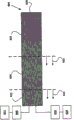
Fig. 1 is the schematic diagram of vapotherapy system.
Fig. 2 is the enlarged drawing for the conduit of the vapotherapy system of Fig. 1.
Fig. 3 a-3b shows the electrod-array in the conduit that is arranged on vapotherapy system.
Fig. 4 a-4b shows another embodiment of the electrod-array in the conduit that is arranged on vapotherapy system.
Fig. 5 shows another embodiment of vapotherapy system.
Fig. 6 a-6c shows the steam generation chamber that is applicable to producing high-temperature vapour or steam.
Fig. 7 shows another embodiment of the electrod-array in the conduit that is arranged on vapotherapy system.
Fig. 8 a-8b shows another embodiment of the electrod-array in the conduit that is arranged on vapotherapy system.
Detailed Description Of The Invention
An embodiment of the invention provide a kind of vapotherapy system based on conduit, and this system produces steam at far-end.The distal tip of conduit is enough little, thereby not only adapts in GSV, and adapts in the less blood vessel in patient's lower limb.This vapotherapy system can be used for treating varicosis or dwindles therapy (reduction therapy) for venous lumen.According to the steam generation conduit of this embodiment, can make the diameter having in 4Fr to 10Fr scope, vein and/or blood vessel that it can be used for treating ordinary range, comprise that GSV and the master who sends from it prop up, because the diameter of conduit easily fits in these blood vessels.Yet in other embodiments, conduit may be greater than 10Fr or be less than 4Fr.
According to an aspect of the vapotherapy system of this embodiment, be to be positioned at size and efficiency distal end of catheter, that make the thermal source, particularly thermal source of the change of liquid generation vapor phase.In order the tip of steam conduit to be placed on to little tube chamber as being less than the lower limb intravenous of GSV, 7Fr or less conduit diameter may be desirable.Although can produce steam outward and it is delivered to therapentic part by conduit at patient body, away from the steam of therapentic part, produce and conveying can relate to about protection patient and doctor exempts from burn and about carrying the quality of steam or the problem of potential.Yet, in distal end of catheter exit, produce steam and cause the problem about thermal source size and structure.Particularly, thermal source not only must be enough little of to be fitted in catheter tip, and must allow sufficient liquid and flow of vapor, so that the treatment benefit of hope to be provided.
Fig. 1 and Fig. 2 show according to the vapotherapy system 100 of an embodiment of the invention.System 100 comprises conduit 102, electrod-array 104, head 106, pump 108, RF generator 110, fluid storage 112 and steam orifice 114.System 100 also can comprise current limiter 116 and sensor 118.
In this embodiment, fluid can provide from fluid storage 112 conductive pipe 102 by pump 108, and pump 108 can be for example positive displacement pump, peristaltic pump, syringe pump or other fluid metering system.Fluid can be, for example, and sterile physiological (0.9%) saline.Other suitable fluid is possible comprise that other Sterile Saline concentration, as 1%, 2% etc. height oozes the conducting fluid of concentration and 0.8%, 0.7% etc. hypotonic concentration, contains other ionic molecule as the fluid of potassium chloride etc.Except pump, fluid also can distribute as having the bag of saline of press belt from pressurized storage device, and uses valve accurate measurement.Pump or other source of pressurised fluid can transport fluid into conduit, and in conduit, it enters the FLUID TRANSPORTATION chamber that extends to the steam generation chamber 120 in conduit from liquid inlet.Be used for shrinking lower limb vein with before treating varicosis, saline or other liquid can provide to pump from fluid storage (as saline instillation bag), and with low flow velocity, inject conduit with standby mode, for example, per minute 1 drops to 15, to stop blood or other physiological material reverse flow in conduit, and prevention is solidified in conduit or near conduit.In addition, also can in fluid drop, add anticoagulant as heparin, to improve it, stop in catheter body or near the ability of solidifying catheter body.Under standby mode, liquid can ooze from the steam orifice of steam generation conduit.In alternative structure, electrode can be microwave emitter, induction heater, PHOTONIC DEVICE as laser diode, light emitting diode or other discharge photon (light) can device, and be used for vaporific fluid and need not be electric conductivity.
Conduit can be applicable to inserting in the blood vessel of patient's lower limb.In one embodiment, the external diameter of conduit can form as Pebax, polyamide, nylon, Hytrel or other biocompatible plastic, rubber, thermosetting, thermoplasticity or elastomeric material by polyimides or by any other suitable material.Catheter shaft also can weave to improve antitorque knot ability and breaking strength or can promotion (pushability).
The distal tip of conduit has one or more vapor outlet port 114 in downstream or the distally of current limiter.For example, the steam generation conduit shown in Fig. 1 and Fig. 2 can have rustless steel point, is formed with side vapor outlet port in rustless steel point.As required, other vapor outlet port can be arranged around girth and/or on far-end.In addition, vapor outlet port can be positioned on the front end of conduit, to allow steam to distribute forward.Some suitable vapor outlet port structure example are as shown at USSN 61/059,518, and its disclosure is hereby incorporated by.
In the embodiment shown in Fig. 1, optional head 106 can be set at the near-end of conduit, to facilitate, place and mobile conduit.With being connected and can being undertaken by head with being connected of power supply of fluid supply.The length of head and conduit itself can change, to adapt to the application of expection.For example, in order to treat the vein of people's lower limb, the length of the conduit in head distally can be 10cm to 100cm, still, can manufacture longer length to adapt to longer lower limb.
As shown in Figure 1-2, steam generation chamber 120 can comprise the electrod-array 104 with especially little form factor.Steam generation chamber can be arranged on the distal part of conduit 102, and is communicated with fluid storage 512 and steam orifice 514 fluids.Steam generation chamber also can be positioned at the optional position of catheter shaft length, or even in head.Electrod-array can be, for example, and the combination of bipolar electrode or bipolar electrode array, monopolar electrode or monopolar electrode array or bipolar electrode array and monopolar electrode array.In some embodiments, electrod-array comprises a plurality of bipolar electrodes of flat structure.Electrode pair can form conducting wire (conductive traces) in conduit.In one embodiment, for example, electrode pair can be formed on thin polyimide membrane by 2 ounces of copper cash of 6 inches long that 0.010-0.015 inch is wide, the band of interval 0.010-0.015 inch.As shown in Fig. 3 a and 3b, electrod-array can comprise 6 electrode pairs.Yet, in other embodiments, can use the electrode pair of any number.
Fig. 3 a-3b shows an embodiment of the electrod-array 304 that is arranged on conduit 302 distal parts.Electrod-array comprises a plurality of electrodes 305, and these electrodes form steam generation chamber 320 along interior all long arraies of conduit.As shown in Figure 3 a, electrod-array 304 can comprise 6 pairs of flat electrodes.In other embodiments, electrod-array can comprise the electrode 305 of any number.Electrod-array as shown in Fig. 3 a-3b for example can extend 15cm along the length of conduit 302.Electrod-array can be set to produce high-temperature vapour or steam in steam generation chamber 320.
Fig. 4 a-4b shows an alternate embodiments of the electrod-array 404 that is arranged on conduit 402 distal parts.Electrod-array comprises a plurality of electrodes 405, and these electrode arrangement form a pair of steam generation chamber 420a and 420b.As shown in Fig. 4 a, electrod-array 404 can comprise 8 pairs of electrodes.Yet in other embodiments, electrod-array can comprise the electrode 405 of any number.Electrod-array can be set to produce high-temperature vapour or steam in steam generation chamber 420a and 420b.
Fig. 7 shows another embodiment of the electrod-array 704 of the distal part that is arranged on conduit 702.Electrod-array comprises a plurality of electrodes 705, and these electrode arrangement form steam generation chamber 720, as mentioned above.In addition, non-conductive filler material 734 can axially be placed in steam generation chamber, to improve energy density.Filler material 734 can be flexible, as has siloxanes bar or the polyimide tube of the end of jam-pack.Because energy density is the highest in the region near electrode, minimum in the region near steam generation chamber central axis, (filler material can shift low energy densities region, center near steam generation chamber) fluid, and force fluid only at high-density region (that is, near electrode), to flow.In addition, any electrode that non-conductive filler can short circuit may not come in contact.
Fig. 8 a-8b shows an alternate embodiments of the electrod-array 804 that is arranged on conduit 802 distal parts.This electrod-array comprises a plurality of electrodes 805, and these electrodes 805 are arranged and formed steam generation chamber 820.As shown in Figure 8 a-8b, electrod-array 804 can be included in the roll film that all carries electrode 805 on end face and bottom surface.In another embodiment, electrode can only be positioned in a side of roll film (that is, being positioned on the end face or bottom surface of roll film).Roll film can screw winding and is placed in conduit 802.Conducting fluid as above can be transported to the steam generating region 820 between the roll film of electrode.This specific embodiment can make the electrode surface in conduit 802 maximize, thereby the Thermogenesis of conduit is maximized.Due to more multi-electrode and fluid contact in this embodiment, within the given time, can there is more multithread body to be heated, this can make steam carry to maximize.Referring to Fig. 1, electrod-array described herein can be connected to the energy again, as RF generator 110.In one embodiment, RF generator can be the RF generator of 350W, 460kHz.In another embodiment, the energy can be the microwave generator for example moving with 915MHz or 2.45GHz.In another embodiment, the energy can be that the power supply of energy is provided to PHOTONIC DEVICE.In the time of suitably, also can use other suitable RF, microwave or photon source.In some embodiments, this system can comprise optional controller 128.Controller can be integrated with RF generator, or can be independent system component.In some embodiments, system can comprise sensor, as temperature or pressure transducer (not shown).This system, as controller or sensor, can monitor the flow velocity of fluid of conductive pipe conveying, the electrod-array in the impedance of the power level of generator and frequency, electrod-array and/or resistance and steam generation chamber or the temperature of fluid.In some embodiments, controller can be according to the signal of sensing, and as the impedance of sensing, resistance, electric conductivity, flow velocity, temperature, pressure, refractive index, mass flow or volume flow, the parameter of regulating system, as the power of rate of flow of fluid or RF generator.In other embodiments, parameter can manual adjustments.
Electrod-array can be around the steam generation chamber 120 that is arranged on fluid supply exit, chamber.As shown in Fig. 3 a-3b and 4a-4b, steam generation chamber can be positioned the distal part of conduit.Current limiter 116 can be arranged between steam generation chamber and vapor outlet port 114.The size of current limiter can guarantee that the pressure in steam generation chamber is enough high, thereby makes steam overheated when leaving conduit.Steam can be in the scope of 100-140 degree when leaving conduit, if or wish higher quality of steam, may be higher.In the embodiment shown in Fig. 1 and Fig. 2, current limiter forms by using high-temperature adhesives to be bonded in the porous PTFE of appropriate location in conduit.In other embodiments, the filtering material based on metal, duckbill valve, ball check valve, microcavity or mobile control hole can be used as current limiter.
Fig. 5 shows the vapotherapy system 500 according to one embodiment of the present invention.System 500 comprises main body 502, electrod-array 504, piston (pump) 508, RF generator 510, fluid storage 512 and delivery needle 514.System 500 also can comprise sensor 518.The electrod-array 504 of system 500, RF generator 510, fluid storage 512, pressurized with fluid and distribution control system and sensor 518 can correspond respectively to above-mentioned electrod-array 104,304,404, RF generator 110, fluid storage 112 and sensor 118.Yet the vapotherapy system 500 that comprises steam delivery needle 514 shown in Fig. 5 may be more suitable for entering and treat little superficial vein and/or surperficial varicosis than the system of Fig. 1 100.
For example, pin can be arranged on the far-end of the conveyor chamber of elongated member described herein.Once produce steam and be transported to outside needle point, steam just can easily move and successfully pass distortion by vein; In the whole treatment length of hope, do not need to realize entering of conduit or pin.The extensive network of therefore, treating superficial vein little or distortion may only need the acupuncture of one or decreased number.Pin can be the hypodermic needle of standard, or can comprise other steam orifice.The outer shaft of pin can be heat insulation, passively by adding on its outer surface low Heat Conduction Material, or by comprising active cooling collet.
Fig. 6 a-6c shows and is adapted at elongated member as produced the steam generation chamber 620 of high-temperature vapour or steam in above-mentioned conduit or elongate body.In some embodiments, steam generation chamber can be arranged on and be applicable to inserting in the elongate body of patient's vein, for example, for venous lumen, dwindle treatment.In other embodiments, this chamber can be positioned at patient outside.Steam generation chamber 620 comprises electrod-array 604, can be any electrod-array described herein.In addition, steam generation chamber 620 can be connected to RF generator 610, pump 608, fluid storage 612 and controller 628, and it can comprise described herein or RF generator known in the art and fluid storage.As mentioned above, in some embodiments, controller 628 can be integrated with RF generator, also can be separated with RF generator.
With reference now to Fig. 6 a-6c, a kind of method that produces steam in conduit or other elongated delivery device is discussed.Referring to Fig. 6 a, fluid can be transported to steam generation chamber 620 from fluid storage 612 by pump 608 or other pressue device.Fluid can be Sterile Saline or any other suitable fluid.Fluid can be carried with constant or variable rate of flow of fluid.For example, in one embodiment, preferred constant flow rate is about 3ml/min.In some embodiments, controller 610 can be controlled and regulated fluid flow velocity.
Next, RF generator 610 can provide power for the electrode 604 being arranged in steam generation chamber 620.In the production process of steam, convection cell steam generation chamber can describe with regard to three different regions, comprises 622, steam generation district, heating region 624 and fully forms steam dome 626.When fluid flows through steam generation chamber and provide power to electrode, fluid is heated in heating region 622.When fluid is heated to as lower in atmospheric pressure 100 degrees Celsius of enough temperature, fluid starts to change into steam or steam in steam generation district 624.Then when arriving abundant formation steam dome 626, all fluids can change steam into, and it can leave the far-end of steam generation chamber and leave conduit afterwards.If the pressure in chamber, higher than atmospheric pressure, needs higher temperature, if lower than atmospheric pressure, lower temperature can produce steam.
In steam production process, can sensing corresponding to the signal of vapotherapy system to determine whether fluid had fully formed steam before the far-end that leaves steam generation chamber.In some embodiments, by controller 628 sensing signals.Whether sensing steam fully forms is particularly useful for many surgery application, as varicosis treatment, in this application, to vein, carries the steam of high-quality abundant formation to cause more effective treatment.In one embodiment, electrical impedance that can sensor electrode array.In other embodiments, can the temperature of sensing fluid, the temperature of electrod-array, rate of flow of fluid, pressure or similarly parameter.
The signal of sensing can be indicated heating region, the steam generation district in steam generation chamber and fully be formed size separately and/or the position of steam dome.For example, when more fluid is included in steam generation chamber 620 when interior, the impedance of electrod-array reduces.If the power that is transported to electrod-array is along with the reduction of impedance keeps constant, heating region, steam generation district and fully form steam dome and will in steam generation chamber, distad move, as shown in the arrow 630 in Fig. 6 b.If it is distad mobile too far away fully to form steam dome 626, fluid may leave steam generation chamber before being fully converted into steam.In addition,, in the time of in less fluid is included in steam generation chamber, the impedance of electrod-array will improve.If the power that is transported to electrod-array keeps constant along with impedance raises, heating region, steam generation district and fully form steam dome and will in steam generation chamber, move by proximad, as shown in the arrow 632 in Fig. 6 c.When abundant formation steam dome 626 proximads move, produce the steam of better quality, still, must optimize this region to guarantee to produce enough vapor volumes.
Therefore, the power that is transported to electrod-array can regulate according to the signal of sensing, fully to form steam in the steam generating region in steam generation chamber.This allows vapotherapy system described herein from conduit to target tissue, to carry the steam fully forming.In some embodiments, power can regulate by controller 628.In other embodiments, power can regulate by the operation of RF generator itself.For example, if the signal of sensing is the impedance of electrod-array, the power that is transported to electrod-array can raise along with the reduction of impedance, to guarantee that steam fully formed before leaving steam generation chamber.If impedance raises, the power that is transported to electrod-array can reduce, to maintain the desired quantity of the thermal treatment zone in steam generating region.
In other embodiments, other systematic parameter can regulate according to the signal of sensing.In one embodiment, can regulated fluid enter the flow velocity of steam generation chamber, fully to form steam in the steam generating region at steam chamber.For example, if the signal of sensing is the impedance of electrod-array, and impedance rising, flow velocity can improve, to maintain the relative position of steam generating region.Similarly, if impedance reduces, the flow velocity of fluid can reduce.As mentioned above, systematic parameter can regulate automatically by controller 628, or can manual adjustments.
In order to provide thermal therapeutical to vein, patient's vein can be inserted in the tip, distally of steam generation conduit, tip, distally is placed on to the venous lumen contracted position of hope.Ultrasonic or fluoroscopy can be used for subsidiary conduit and place.
Then can with the speed of for example 1-5ml/min, to steam generation conduit, provide saline or other liquid by pump, and RF generator can provide power to electrod-array.Flow rate of liquid and the RF power level providing are separate, and wherein one or two can regulate according to the signal of the size of vein, vein flow velocity and/or sensing.In addition, thermoelectricity occasionally other temperature measuring equipment can be arranged on the far-end of steam generation conduit, to provide feedback according to steam temperature to generator.As mentioned above, generator also can be controlled based on electrode impedance, to guarantee the only having steam of abundant formation to be transported to vein from conduit.
Due to steam condensation on vein tissue, potential or heat that evaporation discharges inwardly shrink wall of vein.In order to treat the vein of a segment length, when carrying steam, the distal tip of steam generation conduit can be to pulling back, for example, with the speed of about 1cm/sec.Certainly, the actual speed of pulling back depends primarily on volume and the temperature of the steam of vein diameter and conveying.
Other details of being correlated with about the present invention, material and manufacturing technology can be used the materials and methods in the level of various equivalent modifications.The aspect that the present invention is based on method is being also like this aspect other effect common or that logic is used.In addition, any optional feature of the version of the present invention described in can considering can be set forth independently and be claimed, or gets up to set forth also claimed with any or multiple characteristics combination described herein.Equally, mention singular item and comprise the probability that has plural identical entry.More specifically, as the singulative " " using in the specification and claims, " a kind of ", " as described in ", comprise the object of plural form, unless clearly stated and be not like this in context.Please further note, claim may be written as and not comprise any optional key element.Therefore, this statement is intended to quote relevant basis of limiting as the exclusiveness terms such as " separately ", " only " or use " negative " as using with claim key element.Unless otherwise defined in this, all technology used herein and scientific terminology all have the identical implication of conventionally understanding with one skilled in the art of the present invention.Scope of the present invention is not subject to the restriction of this description, and only by its ordinary meaning of the claim of using, is limited.
Claims (9)
1. a steam generating device, comprising:
Wherein be provided with the steam generation chamber of electrod-array, described electrod-array comprises the flat electrode of a plurality of length longitudinal extensions along described steam generation chamber;
The fluid storage being connected with steam generation chamber;
The RF generator being connected with electrod-array; With
Controller, it is set to by RF generator, be transported to the power of electrod-array according to the Signal Regulation in the steam generation chamber of sensing, the fluid from fluid storage is converted in steam generation chamber to the steam of abundant formation; The signal of wherein said sensing is the impedance of electrod-array.
2. the device of claim 1, the power of wherein carrying reduces along with the rising of the impedance of sensing.
3. the device of claim 1, wherein said electrod-array is along the interior girth setting of conduit.
4. the device of claim 1, also comprises the second steam generation chamber, is also provided with the electrode of described electrod-array in this second steam generation chamber, and described fluid storage is connected with the second steam generation chamber.
5. the device of claim 1, wherein said liquid is saline.
6. the device of claim 1, the power that wherein said controller regulates described RF generator to carry to described electrod-array based on described sensing signal automatically.
7. the device of claim 1, also comprises the delivery needle being connected with steam generation chamber, the steam that this delivery needle is set to fully form to targeted delivery.
8. the device of claim 1, wherein said electrod-array is bipolar electrode array.
9. the device of claim 1, wherein fluid is delivered to steam generation chamber by fluid storage with time-varying rate.
Applications Claiming Priority (5)
| Application Number | Priority Date | Filing Date | Title |
|---|---|---|---|
| US11586408P | 2008-11-18 | 2008-11-18 | |
| US61/115,864 | 2008-11-18 | ||
| US22829809P | 2009-07-24 | 2009-07-24 | |
| US61/228,298 | 2009-07-24 | ||
| PCT/US2009/064894 WO2010059659A2 (en) | 2008-11-18 | 2009-11-18 | Hot tip vein therapy device |
Publications (2)
| Publication Number | Publication Date |
|---|---|
| CN102256559A CN102256559A (en) | 2011-11-23 |
| CN102256559B true CN102256559B (en) | 2014-02-26 |
Family
ID=42198774
Family Applications (1)
| Application Number | Title | Priority Date | Filing Date |
|---|---|---|---|
| CN200980146226.XA Expired - Fee Related CN102256559B (en) | 2008-11-18 | 2009-11-18 | Hot tip vein therapy device |
Country Status (7)
| Country | Link |
|---|---|
| US (1) | US20110264176A1 (en) |
| EP (1) | EP2355733A4 (en) |
| JP (1) | JP5595410B2 (en) |
| CN (1) | CN102256559B (en) |
| AU (1) | AU2009316747A1 (en) |
| CA (1) | CA2742996A1 (en) |
| WO (1) | WO2010059659A2 (en) |
Families Citing this family (17)
| Publication number | Priority date | Publication date | Assignee | Title |
|---|---|---|---|---|
| JP2011522633A (en) * | 2008-06-06 | 2011-08-04 | バリックス・メディカル・コーポレイション | Vascular treatment device and method |
| JP2012508067A (en) | 2008-11-06 | 2012-04-05 | エヌエックスセラ インコーポレイテッド | System and method for treatment of prostate tissue |
| JP2012508069A (en) | 2008-11-06 | 2012-04-05 | エヌエックスセラ インコーポレイテッド | System and method for treatment of benign prostatic hyperplasia |
| US20100198209A1 (en) * | 2009-01-30 | 2010-08-05 | Tartaglia Joseph M | Hemorrhoid Therapy and Method |
| US9833277B2 (en) | 2009-04-27 | 2017-12-05 | Nxthera, Inc. | Systems and methods for prostate treatment |
| DK2755614T3 (en) | 2011-09-13 | 2017-12-04 | Nxthera Inc | PROSTATE TREATMENT SYSTEMS |
| US10335222B2 (en) | 2012-04-03 | 2019-07-02 | Nxthera, Inc. | Induction coil vapor generator |
| US20130268036A1 (en) * | 2012-04-04 | 2013-10-10 | Sean Morris | Apparatus and Method of Treating a Vein with Heat Energy |
| JP2016513563A (en) | 2013-03-14 | 2016-05-16 | エヌエックスセラ インコーポレイテッド | System and method for treating prostate cancer |
| JP6422975B2 (en) * | 2013-12-10 | 2018-11-14 | エヌエックスセラ インコーポレイテッド | Steam ablation system and method |
| US9968395B2 (en) | 2013-12-10 | 2018-05-15 | Nxthera, Inc. | Systems and methods for treating the prostate |
| WO2016123498A1 (en) | 2015-01-29 | 2016-08-04 | Nxthera, Inc. | Vapor ablation systems and methods |
| WO2016183475A1 (en) | 2015-05-13 | 2016-11-17 | Nxthera, Inc. | Systems and methods for treating the bladder with condensable vapor |
| EP3558139A4 (en) | 2016-12-21 | 2020-08-12 | Nxthera, Inc. | Vapor ablation systems and methods |
| JP7193463B2 (en) | 2017-01-06 | 2022-12-20 | ボストン サイエンティフィック サイムド,インコーポレイテッド | Transperitoneal steam ablation system and method |
| CN108066003A (en) * | 2017-12-29 | 2018-05-25 | 浙江归创医疗器械有限公司 | Ablation catheter |
| KR102207496B1 (en) * | 2018-12-13 | 2021-01-25 | 이경용 | Apparatus for varicose veins treatment dual tube structure catheter, vascular adhesion method using the same |
Citations (3)
| Publication number | Priority date | Publication date | Assignee | Title |
|---|---|---|---|---|
| US5556396A (en) * | 1994-01-18 | 1996-09-17 | Endovascular, Inc. | Method for tubal electroligation |
| WO2003049631A1 (en) * | 2001-12-12 | 2003-06-19 | Tissuelink Medical, Inc. | Fluid-assisted medical devices, systems and methods |
| US6911028B2 (en) * | 1998-10-28 | 2005-06-28 | John H. Shadduck | Medical instrument working end and method for endoluminal treatments |
Family Cites Families (11)
| Publication number | Priority date | Publication date | Assignee | Title |
|---|---|---|---|---|
| US5437664A (en) * | 1994-01-18 | 1995-08-01 | Endovascular, Inc. | Apparatus and method for venous ligation |
| US5891134A (en) * | 1996-09-24 | 1999-04-06 | Goble; Colin | System and method for applying thermal energy to tissue |
| US7674259B2 (en) | 2000-12-09 | 2010-03-09 | Tsunami Medtech | Medical instruments and techniques for thermally-mediated therapies |
| US6669694B2 (en) * | 2000-09-05 | 2003-12-30 | John H. Shadduck | Medical instruments and techniques for highly-localized thermally-mediated therapies |
| US5989212A (en) * | 1998-06-04 | 1999-11-23 | Alcon Laboratories, Inc. | Pumping chamber for a liquefaction handpiece having a countersink electrode |
| US6379350B1 (en) * | 1999-10-05 | 2002-04-30 | Oratec Interventions, Inc. | Surgical instrument for ablation and aspiration |
| AU2002239929A1 (en) * | 2001-01-16 | 2002-07-30 | Novacept | Apparatus and method for treating venous reflux |
| WO2002069821A1 (en) * | 2001-03-06 | 2002-09-12 | Thermemed Corp. | Vaporous delivery of thermal energy to tissue sites |
| US8579892B2 (en) * | 2003-10-07 | 2013-11-12 | Tsunami Medtech, Llc | Medical system and method of use |
| US20070088346A1 (en) * | 2005-10-14 | 2007-04-19 | Mirizzi Michael S | Method and apparatus for varicose vein treatment using acoustic hemostasis |
| JP2011522633A (en) * | 2008-06-06 | 2011-08-04 | バリックス・メディカル・コーポレイション | Vascular treatment device and method |
-
2009
- 2009-11-18 EP EP09828130A patent/EP2355733A4/en not_active Withdrawn
- 2009-11-18 WO PCT/US2009/064894 patent/WO2010059659A2/en active Application Filing
- 2009-11-18 CA CA2742996A patent/CA2742996A1/en not_active Abandoned
- 2009-11-18 JP JP2011537561A patent/JP5595410B2/en not_active Expired - Fee Related
- 2009-11-18 US US13/126,513 patent/US20110264176A1/en not_active Abandoned
- 2009-11-18 AU AU2009316747A patent/AU2009316747A1/en not_active Abandoned
- 2009-11-18 CN CN200980146226.XA patent/CN102256559B/en not_active Expired - Fee Related
Patent Citations (3)
| Publication number | Priority date | Publication date | Assignee | Title |
|---|---|---|---|---|
| US5556396A (en) * | 1994-01-18 | 1996-09-17 | Endovascular, Inc. | Method for tubal electroligation |
| US6911028B2 (en) * | 1998-10-28 | 2005-06-28 | John H. Shadduck | Medical instrument working end and method for endoluminal treatments |
| WO2003049631A1 (en) * | 2001-12-12 | 2003-06-19 | Tissuelink Medical, Inc. | Fluid-assisted medical devices, systems and methods |
Also Published As
| Publication number | Publication date |
|---|---|
| WO2010059659A8 (en) | 2010-07-08 |
| EP2355733A2 (en) | 2011-08-17 |
| JP2012509151A (en) | 2012-04-19 |
| WO2010059659A2 (en) | 2010-05-27 |
| CN102256559A (en) | 2011-11-23 |
| WO2010059659A3 (en) | 2010-08-26 |
| EP2355733A4 (en) | 2012-11-14 |
| US20110264176A1 (en) | 2011-10-27 |
| CA2742996A1 (en) | 2010-05-27 |
| AU2009316747A1 (en) | 2011-06-30 |
| JP5595410B2 (en) | 2014-09-24 |
Similar Documents
| Publication | Publication Date | Title |
|---|---|---|
| CN102256559B (en) | Hot tip vein therapy device | |
| US11801084B2 (en) | Methods and devices to treat nasal airways | |
| US11759222B2 (en) | Methods and devices to treat nasal airways | |
| US10456185B2 (en) | Methods and devices to treat nasal airways | |
| US11241271B2 (en) | Methods of treating nasal airways | |
| CN103179914B (en) | Microwave catheter equipment for renal nerve regulation | |
| EP3586779B1 (en) | Devices to treat nasal airways | |
| US6726708B2 (en) | Therapeutic heating and cooling via temperature management of a colon-inserted balloon | |
| CN105636644A (en) | Devices, systems, and methods for the selective positioning of an intravascular ultrasound neuromodulation device | |
| CN103547229A (en) | Cryoablation apparatuses, systems, and methods for renal neuromodulation | |
| JP4602322B2 (en) | Urinary tract disease treatment system and method | |
| EP2477571B1 (en) | Hot tip laser generated vapor vein therapy device |
Legal Events
| Date | Code | Title | Description |
|---|---|---|---|
| C06 | Publication | ||
| PB01 | Publication | ||
| C10 | Entry into substantive examination | ||
| SE01 | Entry into force of request for substantive examination | ||
| C14 | Grant of patent or utility model | ||
| GR01 | Patent grant | ||
| CF01 | Termination of patent right due to non-payment of annual fee |
Granted publication date: 20140226 Termination date: 20151118 |
|
| CF01 | Termination of patent right due to non-payment of annual fee |