CN102458312A - Patient-adapted and improved orthopedic implants, designs and related tools - Google Patents

Patient-adapted and improved orthopedic implants, designs and related tools Download PDF

Info

Publication number
CN102458312A
CN102458312A CN2010800284889A CN201080028488A CN102458312A CN 102458312 A CN102458312 A CN 102458312A CN 2010800284889 A CN2010800284889 A CN 2010800284889A CN 201080028488 A CN201080028488 A CN 201080028488A CN 102458312 A CN102458312 A CN 102458312A
Authority
CN
China
Prior art keywords
tibia
patient
insert
implant
joint
Prior art date
Legal status (The legal status is an assumption and is not a legal conclusion. Google has not performed a legal analysis and makes no representation as to the accuracy of the status listed.)
Pending
Application number
CN2010800284889A
Other languages
Chinese (zh)
Inventor
R·A·博贾斯基
P·郎
N·晁
W·菲茨
J·斯莱明
D·斯坦纳斯
Current Assignee (The listed assignees may be inaccurate. Google has not performed a legal analysis and makes no representation or warranty as to the accuracy of the list.)
Imaging Therapeutics Inc
Original Assignee
Imaging Therapeutics Inc
Priority date (The priority date is an assumption and is not a legal conclusion. Google has not performed a legal analysis and makes no representation as to the accuracy of the date listed.)
Filing date
Publication date
Family has litigation
First worldwide family litigation filed litigation Critical https://patents.darts-ip.com/?family=43386862&utm_source=google_patent&utm_medium=platform_link&utm_campaign=public_patent_search&patent=CN102458312(A) "Global patent litigation dataset” by Darts-ip is licensed under a Creative Commons Attribution 4.0 International License.
Application filed by Imaging Therapeutics Inc filed Critical Imaging Therapeutics Inc
Priority to CN201710002542.6A priority Critical patent/CN107411852A/en
Publication of CN102458312A publication Critical patent/CN102458312A/en
Pending legal-status Critical Current

Links

Images

Classifications

    • AHUMAN NECESSITIES
    • A61MEDICAL OR VETERINARY SCIENCE; HYGIENE
    • A61FFILTERS IMPLANTABLE INTO BLOOD VESSELS; PROSTHESES; DEVICES PROVIDING PATENCY TO, OR PREVENTING COLLAPSING OF, TUBULAR STRUCTURES OF THE BODY, e.g. STENTS; ORTHOPAEDIC, NURSING OR CONTRACEPTIVE DEVICES; FOMENTATION; TREATMENT OR PROTECTION OF EYES OR EARS; BANDAGES, DRESSINGS OR ABSORBENT PADS; FIRST-AID KITS
    • A61F2/00Filters implantable into blood vessels; Prostheses, i.e. artificial substitutes or replacements for parts of the body; Appliances for connecting them with the body; Devices providing patency to, or preventing collapsing of, tubular structures of the body, e.g. stents
    • A61F2/02Prostheses implantable into the body
    • A61F2/30Joints
    • A61F2/3094Designing or manufacturing processes
    • A61F2/30942Designing or manufacturing processes for designing or making customized prostheses, e.g. using templates, CT or NMR scans, finite-element analysis or CAD-CAM techniques
    • AHUMAN NECESSITIES
    • A61MEDICAL OR VETERINARY SCIENCE; HYGIENE
    • A61BDIAGNOSIS; SURGERY; IDENTIFICATION
    • A61B34/00Computer-aided surgery; Manipulators or robots specially adapted for use in surgery
    • A61B34/10Computer-aided planning, simulation or modelling of surgical operations
    • AHUMAN NECESSITIES
    • A61MEDICAL OR VETERINARY SCIENCE; HYGIENE
    • A61BDIAGNOSIS; SURGERY; IDENTIFICATION
    • A61B17/00Surgical instruments, devices or methods, e.g. tourniquets
    • A61B17/14Surgical saws ; Accessories therefor
    • A61B17/15Guides therefor
    • A61B17/154Guides therefor for preparing bone for knee prosthesis
    • A61B17/155Cutting femur
    • AHUMAN NECESSITIES
    • A61MEDICAL OR VETERINARY SCIENCE; HYGIENE
    • A61BDIAGNOSIS; SURGERY; IDENTIFICATION
    • A61B17/00Surgical instruments, devices or methods, e.g. tourniquets
    • A61B17/14Surgical saws ; Accessories therefor
    • A61B17/15Guides therefor
    • A61B17/154Guides therefor for preparing bone for knee prosthesis
    • A61B17/157Cutting tibia
    • AHUMAN NECESSITIES
    • A61MEDICAL OR VETERINARY SCIENCE; HYGIENE
    • A61FFILTERS IMPLANTABLE INTO BLOOD VESSELS; PROSTHESES; DEVICES PROVIDING PATENCY TO, OR PREVENTING COLLAPSING OF, TUBULAR STRUCTURES OF THE BODY, e.g. STENTS; ORTHOPAEDIC, NURSING OR CONTRACEPTIVE DEVICES; FOMENTATION; TREATMENT OR PROTECTION OF EYES OR EARS; BANDAGES, DRESSINGS OR ABSORBENT PADS; FIRST-AID KITS
    • A61F2/00Filters implantable into blood vessels; Prostheses, i.e. artificial substitutes or replacements for parts of the body; Appliances for connecting them with the body; Devices providing patency to, or preventing collapsing of, tubular structures of the body, e.g. stents
    • A61F2/02Prostheses implantable into the body
    • A61F2/30Joints
    • A61F2/38Joints for elbows or knees
    • A61F2/3836Special connection between upper and lower leg, e.g. constrained
    • A61F2/384Special connection between upper and lower leg, e.g. constrained hinged, i.e. with transverse axle restricting the movement
    • AHUMAN NECESSITIES
    • A61MEDICAL OR VETERINARY SCIENCE; HYGIENE
    • A61FFILTERS IMPLANTABLE INTO BLOOD VESSELS; PROSTHESES; DEVICES PROVIDING PATENCY TO, OR PREVENTING COLLAPSING OF, TUBULAR STRUCTURES OF THE BODY, e.g. STENTS; ORTHOPAEDIC, NURSING OR CONTRACEPTIVE DEVICES; FOMENTATION; TREATMENT OR PROTECTION OF EYES OR EARS; BANDAGES, DRESSINGS OR ABSORBENT PADS; FIRST-AID KITS
    • A61F2/00Filters implantable into blood vessels; Prostheses, i.e. artificial substitutes or replacements for parts of the body; Appliances for connecting them with the body; Devices providing patency to, or preventing collapsing of, tubular structures of the body, e.g. stents
    • A61F2/02Prostheses implantable into the body
    • A61F2/30Joints
    • A61F2/38Joints for elbows or knees
    • A61F2/3859Femoral components
    • AHUMAN NECESSITIES
    • A61MEDICAL OR VETERINARY SCIENCE; HYGIENE
    • A61FFILTERS IMPLANTABLE INTO BLOOD VESSELS; PROSTHESES; DEVICES PROVIDING PATENCY TO, OR PREVENTING COLLAPSING OF, TUBULAR STRUCTURES OF THE BODY, e.g. STENTS; ORTHOPAEDIC, NURSING OR CONTRACEPTIVE DEVICES; FOMENTATION; TREATMENT OR PROTECTION OF EYES OR EARS; BANDAGES, DRESSINGS OR ABSORBENT PADS; FIRST-AID KITS
    • A61F2/00Filters implantable into blood vessels; Prostheses, i.e. artificial substitutes or replacements for parts of the body; Appliances for connecting them with the body; Devices providing patency to, or preventing collapsing of, tubular structures of the body, e.g. stents
    • A61F2/02Prostheses implantable into the body
    • A61F2/30Joints
    • A61F2/38Joints for elbows or knees
    • A61F2/389Tibial components
    • AHUMAN NECESSITIES
    • A61MEDICAL OR VETERINARY SCIENCE; HYGIENE
    • A61FFILTERS IMPLANTABLE INTO BLOOD VESSELS; PROSTHESES; DEVICES PROVIDING PATENCY TO, OR PREVENTING COLLAPSING OF, TUBULAR STRUCTURES OF THE BODY, e.g. STENTS; ORTHOPAEDIC, NURSING OR CONTRACEPTIVE DEVICES; FOMENTATION; TREATMENT OR PROTECTION OF EYES OR EARS; BANDAGES, DRESSINGS OR ABSORBENT PADS; FIRST-AID KITS
    • A61F2/00Filters implantable into blood vessels; Prostheses, i.e. artificial substitutes or replacements for parts of the body; Appliances for connecting them with the body; Devices providing patency to, or preventing collapsing of, tubular structures of the body, e.g. stents
    • A61F2/50Prostheses not implantable in the body
    • A61F2/5044Designing or manufacturing processes
    • A61F2/5046Designing or manufacturing processes for designing or making customized prostheses, e.g. using templates, finite-element analysis or CAD-CAM techniques
    • AHUMAN NECESSITIES
    • A61MEDICAL OR VETERINARY SCIENCE; HYGIENE
    • A61BDIAGNOSIS; SURGERY; IDENTIFICATION
    • A61B17/00Surgical instruments, devices or methods, e.g. tourniquets
    • A61B17/16Bone cutting, breaking or removal means other than saws, e.g. Osteoclasts; Drills or chisels for bones; Trepans
    • A61B17/17Guides or aligning means for drills, mills, pins or wires
    • A61B17/1739Guides or aligning means for drills, mills, pins or wires specially adapted for particular parts of the body
    • A61B17/1764Guides or aligning means for drills, mills, pins or wires specially adapted for particular parts of the body for the knee
    • AHUMAN NECESSITIES
    • A61MEDICAL OR VETERINARY SCIENCE; HYGIENE
    • A61BDIAGNOSIS; SURGERY; IDENTIFICATION
    • A61B34/00Computer-aided surgery; Manipulators or robots specially adapted for use in surgery
    • A61B34/10Computer-aided planning, simulation or modelling of surgical operations
    • A61B2034/107Visualisation of planned trajectories or target regions
    • AHUMAN NECESSITIES
    • A61MEDICAL OR VETERINARY SCIENCE; HYGIENE
    • A61BDIAGNOSIS; SURGERY; IDENTIFICATION
    • A61B34/00Computer-aided surgery; Manipulators or robots specially adapted for use in surgery
    • A61B34/10Computer-aided planning, simulation or modelling of surgical operations
    • A61B2034/108Computer aided selection or customisation of medical implants or cutting guides
    • AHUMAN NECESSITIES
    • A61MEDICAL OR VETERINARY SCIENCE; HYGIENE
    • A61FFILTERS IMPLANTABLE INTO BLOOD VESSELS; PROSTHESES; DEVICES PROVIDING PATENCY TO, OR PREVENTING COLLAPSING OF, TUBULAR STRUCTURES OF THE BODY, e.g. STENTS; ORTHOPAEDIC, NURSING OR CONTRACEPTIVE DEVICES; FOMENTATION; TREATMENT OR PROTECTION OF EYES OR EARS; BANDAGES, DRESSINGS OR ABSORBENT PADS; FIRST-AID KITS
    • A61F2/00Filters implantable into blood vessels; Prostheses, i.e. artificial substitutes or replacements for parts of the body; Appliances for connecting them with the body; Devices providing patency to, or preventing collapsing of, tubular structures of the body, e.g. stents
    • A61F2/02Prostheses implantable into the body
    • A61F2/30Joints
    • A61F2/38Joints for elbows or knees
    • A61F2/3886Joints for elbows or knees for stabilising knees against anterior or lateral dislocations
    • AHUMAN NECESSITIES
    • A61MEDICAL OR VETERINARY SCIENCE; HYGIENE
    • A61FFILTERS IMPLANTABLE INTO BLOOD VESSELS; PROSTHESES; DEVICES PROVIDING PATENCY TO, OR PREVENTING COLLAPSING OF, TUBULAR STRUCTURES OF THE BODY, e.g. STENTS; ORTHOPAEDIC, NURSING OR CONTRACEPTIVE DEVICES; FOMENTATION; TREATMENT OR PROTECTION OF EYES OR EARS; BANDAGES, DRESSINGS OR ABSORBENT PADS; FIRST-AID KITS
    • A61F2/00Filters implantable into blood vessels; Prostheses, i.e. artificial substitutes or replacements for parts of the body; Appliances for connecting them with the body; Devices providing patency to, or preventing collapsing of, tubular structures of the body, e.g. stents
    • A61F2/02Prostheses implantable into the body
    • A61F2/30Joints
    • A61F2002/30001Additional features of subject-matter classified in A61F2/28, A61F2/30 and subgroups thereof
    • A61F2002/30316The prosthesis having different structural features at different locations within the same prosthesis; Connections between prosthetic parts; Special structural features of bone or joint prostheses not otherwise provided for
    • A61F2002/30317The prosthesis having different structural features at different locations within the same prosthesis
    • A61F2002/30324The prosthesis having different structural features at different locations within the same prosthesis differing in thickness
    • AHUMAN NECESSITIES
    • A61MEDICAL OR VETERINARY SCIENCE; HYGIENE
    • A61FFILTERS IMPLANTABLE INTO BLOOD VESSELS; PROSTHESES; DEVICES PROVIDING PATENCY TO, OR PREVENTING COLLAPSING OF, TUBULAR STRUCTURES OF THE BODY, e.g. STENTS; ORTHOPAEDIC, NURSING OR CONTRACEPTIVE DEVICES; FOMENTATION; TREATMENT OR PROTECTION OF EYES OR EARS; BANDAGES, DRESSINGS OR ABSORBENT PADS; FIRST-AID KITS
    • A61F2/00Filters implantable into blood vessels; Prostheses, i.e. artificial substitutes or replacements for parts of the body; Appliances for connecting them with the body; Devices providing patency to, or preventing collapsing of, tubular structures of the body, e.g. stents
    • A61F2/02Prostheses implantable into the body
    • A61F2/30Joints
    • A61F2002/30001Additional features of subject-matter classified in A61F2/28, A61F2/30 and subgroups thereof
    • A61F2002/30316The prosthesis having different structural features at different locations within the same prosthesis; Connections between prosthetic parts; Special structural features of bone or joint prostheses not otherwise provided for
    • A61F2002/30317The prosthesis having different structural features at different locations within the same prosthesis
    • A61F2002/30327The prosthesis having different structural features at different locations within the same prosthesis differing in diameter
    • AHUMAN NECESSITIES
    • A61MEDICAL OR VETERINARY SCIENCE; HYGIENE
    • A61FFILTERS IMPLANTABLE INTO BLOOD VESSELS; PROSTHESES; DEVICES PROVIDING PATENCY TO, OR PREVENTING COLLAPSING OF, TUBULAR STRUCTURES OF THE BODY, e.g. STENTS; ORTHOPAEDIC, NURSING OR CONTRACEPTIVE DEVICES; FOMENTATION; TREATMENT OR PROTECTION OF EYES OR EARS; BANDAGES, DRESSINGS OR ABSORBENT PADS; FIRST-AID KITS
    • A61F2/00Filters implantable into blood vessels; Prostheses, i.e. artificial substitutes or replacements for parts of the body; Appliances for connecting them with the body; Devices providing patency to, or preventing collapsing of, tubular structures of the body, e.g. stents
    • A61F2/02Prostheses implantable into the body
    • A61F2/30Joints
    • A61F2/3094Designing or manufacturing processes
    • A61F2/30942Designing or manufacturing processes for designing or making customized prostheses, e.g. using templates, CT or NMR scans, finite-element analysis or CAD-CAM techniques
    • A61F2002/30952Designing or manufacturing processes for designing or making customized prostheses, e.g. using templates, CT or NMR scans, finite-element analysis or CAD-CAM techniques using CAD-CAM techniques or NC-techniques
    • AHUMAN NECESSITIES
    • A61MEDICAL OR VETERINARY SCIENCE; HYGIENE
    • A61FFILTERS IMPLANTABLE INTO BLOOD VESSELS; PROSTHESES; DEVICES PROVIDING PATENCY TO, OR PREVENTING COLLAPSING OF, TUBULAR STRUCTURES OF THE BODY, e.g. STENTS; ORTHOPAEDIC, NURSING OR CONTRACEPTIVE DEVICES; FOMENTATION; TREATMENT OR PROTECTION OF EYES OR EARS; BANDAGES, DRESSINGS OR ABSORBENT PADS; FIRST-AID KITS
    • A61F2/00Filters implantable into blood vessels; Prostheses, i.e. artificial substitutes or replacements for parts of the body; Appliances for connecting them with the body; Devices providing patency to, or preventing collapsing of, tubular structures of the body, e.g. stents
    • A61F2/02Prostheses implantable into the body
    • A61F2/30Joints
    • A61F2/3094Designing or manufacturing processes
    • A61F2/30942Designing or manufacturing processes for designing or making customized prostheses, e.g. using templates, CT or NMR scans, finite-element analysis or CAD-CAM techniques
    • A61F2002/3096Designing or manufacturing processes for designing or making customized prostheses, e.g. using templates, CT or NMR scans, finite-element analysis or CAD-CAM techniques trimmed or cut to a customised size
    • AHUMAN NECESSITIES
    • A61MEDICAL OR VETERINARY SCIENCE; HYGIENE
    • A61FFILTERS IMPLANTABLE INTO BLOOD VESSELS; PROSTHESES; DEVICES PROVIDING PATENCY TO, OR PREVENTING COLLAPSING OF, TUBULAR STRUCTURES OF THE BODY, e.g. STENTS; ORTHOPAEDIC, NURSING OR CONTRACEPTIVE DEVICES; FOMENTATION; TREATMENT OR PROTECTION OF EYES OR EARS; BANDAGES, DRESSINGS OR ABSORBENT PADS; FIRST-AID KITS
    • A61F2/00Filters implantable into blood vessels; Prostheses, i.e. artificial substitutes or replacements for parts of the body; Appliances for connecting them with the body; Devices providing patency to, or preventing collapsing of, tubular structures of the body, e.g. stents
    • A61F2/02Prostheses implantable into the body
    • A61F2/30Joints
    • A61F2/38Joints for elbows or knees
    • A61F2002/3895Joints for elbows or knees unicompartimental
    • BPERFORMING OPERATIONS; TRANSPORTING
    • B33ADDITIVE MANUFACTURING TECHNOLOGY
    • B33YADDITIVE MANUFACTURING, i.e. MANUFACTURING OF THREE-DIMENSIONAL [3-D] OBJECTS BY ADDITIVE DEPOSITION, ADDITIVE AGGLOMERATION OR ADDITIVE LAYERING, e.g. BY 3-D PRINTING, STEREOLITHOGRAPHY OR SELECTIVE LASER SINTERING
    • B33Y80/00Products made by additive manufacturing

Landscapes

  • Health & Medical Sciences (AREA)
  • Engineering & Computer Science (AREA)
  • Orthopedic Medicine & Surgery (AREA)
  • Life Sciences & Earth Sciences (AREA)
  • Veterinary Medicine (AREA)
  • Public Health (AREA)
  • General Health & Medical Sciences (AREA)
  • Biomedical Technology (AREA)
  • Heart & Thoracic Surgery (AREA)
  • Animal Behavior & Ethology (AREA)
  • Oral & Maxillofacial Surgery (AREA)
  • Transplantation (AREA)
  • Cardiology (AREA)
  • Vascular Medicine (AREA)
  • Physical Education & Sports Medicine (AREA)
  • Manufacturing & Machinery (AREA)
  • Surgery (AREA)
  • Physics & Mathematics (AREA)
  • Geometry (AREA)
  • Nuclear Medicine, Radiotherapy & Molecular Imaging (AREA)
  • Medical Informatics (AREA)
  • Molecular Biology (AREA)
  • Dentistry (AREA)
  • Robotics (AREA)
  • Prostheses (AREA)

Abstract

Methods and devices are disclosed relating improved articular models, implant components, and related guide tools and procedures. In addition, methods and devices are disclosed relating articular models, implant components, and/or related guide tools and procedures that include one or more features derived from patient-data, for example, images of the patient's joint. The data can be used to create a model for analyzing a patient's joint and to devise and evaluate a course of corrective action. The data also can be used to create patient-adapted implant components and related tools and procedures.

Description

The improvement orthopaedic implants, design and the related tool that adapt to the patient
Related application
The application requires the right of following document: the U. S. application No.61/269 that is entitled as " Patient-Specific Orthopedic Implants And Models " that on June 24th, 2009 submitted to; The U. S. application No.61/284458 that is entitled as " Patient-Adapted And Improved Orthopedic Implants, Designs And Related Tools " of the U. S. application No.61/280493 that is entitled as " Patient-Adapted and Improved Orthopedic Implants; Designs and Related Tools " that submits in the U. S. application No.61/275174 that is entitled as " Patient-Specific Orthopedic Implants And Models " that submits in the U. S. application No.61/273216 that is entitled as " Patient-Specific Orthopedic Implants And Models " that submits in the U. S. application No.61/220726 that is entitled as " Patient-Specific Orthopedic Implants And Models " that 405, submitted on June 26th, 2009, on July 31st, 2009, on August 26th, 2009, on November 4th, 2009, December in 2009 submission on the 18th.
The application also requires the right of the U. S. application No.12/660529 that is entitled as " Patient-Adapted and Improved Orthopedic Implants, Designs, and Related Tools " of submission on February 25th, 2010.
Each of the application of more than describing applies for that here integral body is incorporated into this by reference, and from all purposes, the priority of each application of listing more than the application requires.
Technical field
The application relates to the orthopaedic implants and the guiding tool that improve and/or adapt to patient (for example the patient is exclusive and/or patient special) with and related methods, design and model.
Background technology
Usually, pathological changes, injured or defective joint (for example suffering from arthritic joint) have used the finished product implant of standard and other surgical instrumenties to repair.Concrete for many years finished product implant design is changed, to solve specific question.But in change designed with the process that solves specific question, the frequent variation of history design had produced one or more accessory problems of the design solution that remains in the future.Generally speaking, the many problems in these problems come from patient's existing or healthy joint anatomical structure and implant the one or more difference between the individual features of parts.
Summary of the invention
Adaptation described herein patient's (for example the patient is exclusive and/or patient special) implantation parts can be selected (for example from the storehouse), design (for example design before the art randomly comprises manufacture component or instrument) and/or select and design (the for example characteristic through selecting to have the green part or the instrument of some blank characteristics and then these blank characteristic changes being become the adaptation patient).In addition, for example being used to excise the design of patient's biological structure and the correlation technique of strategy also can be selected and/or design.For example, implant can being selected in the lump and/or designing of parts towards bone surface and the excision strategy that is used for accordingly towards bone surface, make implant parts towards bone surface aspect one or more with mated by removal surface.
In some embodiments, implanting the adaptation patient characteristic of parts, guiding tool or correlation technique can be through being parsed into the picture test data and selecting and/or design (for example before the art of storehouse, selecting and/or design) has implantation parts, guiding tool and/or process for the biological structure coupling of particular patient and/or best characteristic.The imaging test data for example can comprise through x radial imaging, Cone-Beam CT, digital tomography synthetic, ultrasonic; The data (data that for example produce from arthrosis image) in the patient joint that MRI or CT scan or PET or SPECT scanning obtain, these data are processed so that produce the variation on joint or articular portion or IA surface or the form of correction.Some embodiments provide the method and apparatus according to the required model on part that forms joint or joint from the data that have the joint derivation now or surface.For example, these data also can be used to produce model, and model can be used to analyze patient's joint, and formulate and assess the policy of corrective action.These data and/or model also can be used to the implantation parts that design has the exclusive characteristic of one or more patients (for example surface or curvature).
In one aspect; Some embodiments provide a kind of tibia implant that is used for knee replacements; This tibia implant comprises the holder of (a) tibia; Its size and dimension is arranged to roughly be placed on the proximal face of patient's tibia through at least one insert locking mechanism, and (b) first insert, second insert or two first and second tibia inserts.First insert can comprise the first mutual locking mechanism, be used to engage first basal surface on the surface of tibia holder, the first articular surface part roughly relative with first basal surface and between first basal surface and first articular surface in approximate vertical side upwardly extending first thickness.Second insert can comprise the second mutual locking mechanism, be used to engage second basal surface on the surface of tibia holder, the second joint surface portion roughly relative with second basal surface and between second basal surface and second joint surface in approximate vertical side upwardly extending second thickness.In some embodiments, first thickness of first insert is greater than second thickness of second insert.First and second thickness can be for example respectively from the geometric center of first and second contact areas of first and second articular surfaces and/or respectively from the respective edges of first and second contact areas of first and second articular surfaces and/or respectively from the central point of first and second articular surfaces and/or respectively from first and second articular surfaces near the point of first and second basal surfaces and/or respectively from first and second articular surfaces away from the some tolerance of first and second basal surfaces.In some embodiments, first and second thickness can be respectively the average thicknesss of first and second inserts.
In some embodiments, first thickness of first insert can be quite greater than second thickness of second insert.For example, the thickness difference of first and second thickness can be significantly different on statistics.Substitute or in addition, first and second thickness can be significantly different clinically, for example thickness difference is enough to produce clinical effectiveness.Clinical effectiveness can comprise aligning of knee joint at least a portion and/or the balance of knee joint at least a portion.In addition, in some embodiments, first and second inserts of tibia implant can have different curvature and/or on corresponding articular surface part, have different slopes on the corresponding articular surface part.
On the other hand; Some embodiments provide a kind of tibia implant that is used for knee replacements; This tibia implant can comprise the medial tibial insert; It comprises that (i) is used to engage the inner surface and the (ii) articular surface of the general plane of medial tibial support, and it comprises the articular surface platform, and is furnished with the sweep relative with the articular surface of medial femoral condyle therein.Substitute or in addition; The tibia implant can comprise the lateral tibial insert; It comprises that (i) is used to engage the inner surface and the (ii) articular surface of the general plane of lateral tibial support, and it comprises the articular surface platform, and is furnished with the sweep relative with the articular surface of lateral femur condyle therein.In some embodiments, the distance from the inner surface of medial tibial insert to articular surface can be different from the distance from the inner surface of lateral tibial insert to articular surface.
In some embodiments; Minimum range from the inner surface of medial tibial insert to articular surface can be different from the minimum range from the inner surface of lateral tibial insert to articular surface; And/or the ultimate range from the inner surface of medial tibial insert to articular surface can be different from the ultimate range from the inner surface of lateral tibial insert to articular surface, and/or the average distance from the inner surface of medial tibial insert to articular surface can be different from the average distance from the inner surface of lateral tibial insert to articular surface.
In some embodiments, the distance from the inner surface of medial tibial insert to articular surface can quite be different from and/or significantly be different from the distance from the inner surface of lateral tibial insert to articular surface.For example, the distance from the inner surface of medial tibial insert to the central point of articular surface can be different from the distance from the inner surface of lateral tibial insert to the central point of articular surface.Substitute or in addition, the distance from the inner surface of medial tibial insert to the central point of the contact area of articular surface is different from the distance from the inner surface of lateral tibial insert to the central point of the contact area of articular surface.Substitute or in addition, the distance from the inner surface of medial tibial insert to the edge of articular surface is different from the distance from the inner surface of lateral tibial insert to the edge of articular surface.
In some embodiments, inboard and lateral tibial insert can have different curvature in corresponding sweep, and/or different joint surface platform slope.In some embodiments, the slope that is used for the articular surface platform of medial tibial insert can be that the patient is mated with patient's medial tibial platform slope rate, can be that the patient is mated with patient's lateral tibial platform slope rate perhaps.Similarly, in some embodiments, the slope that is used for the articular surface platform of lateral tibial insert can be that the patient is mated with patient's lateral tibial platform slope rate, can be that the patient is mated with patient's medial tibial platform slope rate perhaps.In some embodiments, the tibia implant can have the first tibia holder that comprises the medial tibial support, and the second tibia holder that comprises the lateral tibial support.
On the other hand, some embodiments provide a kind of manufacturing to be used to repair or change the method for patient's knee joint tibia implant.This method comprises one or two following steps (a) according to the knee joint view data, electronics assessment knee joint at least a portion; And (b) at least partly according to assessment, one or more parameters of clear and definite tibia implant.At least partly limited the tibia implant by clear and definite parameter, the tibia implant has first articular surface that is higher than the second joint surface with respect to the knee joint proximal tibia when the tibia implant is implanted on the proximal tibia.In some embodiments; This method also comprises the step of planning surgical result according to patient's knee joint electronic image data; And randomly, can at least partly be limited the surgical result of configuration to realize a plan basically of tibia implant by clear and definite parameter.Surgical result can be the knee joint balance in the surgical procedures, and randomly, the knee joint balance can comprise the knee joint balance in the knee joint balance in the stretching process and/or the bent process that softens.Substitute or in addition, surgical result can be that knee joint is aimed at, and randomly, knee joint is aimed at and can be comprised that the knee joint of dissecting axis is aimed at and/or the knee joint aligning of bio-mechanical axis.In some embodiments, knee joint is aimed at the knee joint that can comprise patient's femur and tibia and is aimed at, for example the linear alignment of patient's femur and tibia and/or rotational alignment.In some embodiments, surgical result can comprise the patient special joint line structure or rebuild, for example patient's knee joint medial chamber is with respect to the structure of the joint line of outer side chamber.
In some embodiments, the method step of electronics assessment knee joint at least a portion can comprise the difference of the relative position of at least a portion of confirming knee joint first and second articular surfaces.Substitute and/or in addition, the step of electronics assessment knee joint at least a portion can comprise confirms the knee joint joint line, for example confirm before the art that knee joint joint line and/or postoperative confirm the knee joint joint line.
On the other hand; Some embodiments provide the method for making the tibia implant, and the tibia implant has and one or more tolerance of patient's biological characteristic or medial tibial insert that its predetermined percentage is mated basically and at least one in the lateral tibial insert.This method comprises the characteristic measure in the preceding patient of affirmation of one or two following steps (a) art joint; And (b) at least one in design medial tibial insert and the lateral tibial insert, with comprise with step (a) in essentially identical characteristic measure or the predetermined percentage of this characteristic measure of affirmation.In some embodiments; Step (b) comprises that Aided Design that uses a computer (CAD) and/or computer aided manufacturing (CAM) design at least one of medial tibial insert and lateral tibial insert; And/or cutting blank insert or insert with blank characteristic, so that form and the roughly the same characteristic measure of step (a) or the predetermined percentage of this characteristic measure.
In some embodiments of this method, the approximate match characteristic measure is selected from the group that comprises following characteristic: basically with the insert of the interior side dimension of respective patient or its predetermined percentage coupling in side dimension, basically with by the insert thickness of the respective thickness of excision patient tissue or its predetermined percentage coupling, basically with the insert peripheral shape of respective patient peripheral shape or its predetermined percentage coupling, basically with the insert surface slope of respective patient slope or its predetermined percentage coupling and basically with the insert surface curvature of respective patient curvature or its predetermined percentage coupling.
In some embodiments, design approximate match or same characteristic features tolerance can comprise the line or the curve of level and smooth patient's biological structure characteristic, so that derive the roughly the same characteristic measure of implant or the predetermined percentage of characteristic measure.
On the other hand, some embodiments are provided for being implanted at patient's knee joint the method for knee joint implant, and this method comprises one or two following steps: (a) prepare the near-end of tibia, to receive implant; And (b) at least one tibia implant is inserted on the preparation near-end of tibia; Make first articular surface of at least one implant engage first articular surface of femur or femur implant, and the second joint of the second joint surface engagement femur of at least one implant or femur implant surface.First articular surface is higher than the second joint surface with respect to the dissection axis of tibia.In some embodiments, the tibia implant comprises the holder of single tibia implant, randomly has single tibia insert, or alternatively has two tibia inserts.In other embodiments, the tibia implant comprises two tibia implant holders, randomly has single tibia insert, or alternatively has two tibia inserts, for example is directed against the single tibia insert of each tibia implant holder of two tibia implants holder.
In some embodiments, this method can comprise that also adjusting first articular surface is with respect to the second joint surface height.In some embodiments, this method also can comprise the aligning of aiming at patient joint, evaluate patient joint and regulate in patient's joint alignment one or more.Regulate the patient joint to will definitely for example comprising rotational alignment, the linear alignment of regulating the patient joint of regulating the patient joint and regulating patient's femur and tibia one or more in aiming at.In some embodiments, this method can comprise the bio-mechanical axis of regulating the patient joint and/or the dissection axis of regulating the patient joint.In some embodiments, this method also can comprise the balance in balance patient joint, evaluate patient joint and regulate in the balance in patient joint one or more.Balance can for example comprise the balance of patient joint in stretching, extension and/or gentle bent process.
In some embodiments, this method also comprises according to patient's knee joint electronic image data plan surgical procedures, for example so that realize predetermined surgical result, and randomly carries out surgical procedures.In some embodiments, the step of this method (b) can realize the surgical result of being scheduled to basically.This surgical result can for example comprise joint balance, joint alignment, insertion first insert, utilize second insert or test insert adjustment, utilize second insert or test insert to regulate aims at, inserts second insert, change second insert or test insert, utilize the 3rd insert or test insert adjustment and utilize the 3rd insert or the test insert is regulated in the aligning one or more with the 3rd insert or test insert.
On the other hand, some embodiments are provided for being implanted into balance in the process of knee joint implant or optimizing the method for ligament tensioning the patient, and this method may further comprise the steps: (a) estimate said patient's inboard joint space distance and tensioning; (b) the said patient's of evaluation joint space, outside distance and tensioning; And (c) select independently inboard and the lateral tibial insert provides suitable clearance distance and tensioning.In some embodiments, selected inboard has different thickness with the lateral tibial insert.In some embodiments, in step (c) selected medial tibial insert be selected from two or more medial tibial inserts with different-thickness and/or in step (c) required lateral tibial insert be selected from and have different thick two or more lateral tibial inserts.One or two selection inboard and the lateral tibial insert can be used to recover basically the inboard and/or the joint space, the outside of patient's nature, and/or can be used for recovering basically the natural mobility of patient.
On the other hand; Some embodiments provide a kind of external member that is implanted into the tibia implant the patient who needs knee joint to change; This external member comprises: (a) tibia holder, this tibia holder comprise the first surface and the opposing second surface that is used to engage the medial tibial insert that is used for this holder is fixed to patient's tibia; And (b) have two or more medial tibial inserts of different-thickness, from these medial tibial inserts, select a medial tibial insert so that engage with the tibia holder.On the other hand; Some embodiments provide a kind of external member that is implanted into the tibia implant the patient who needs knee joint to change; This external member comprises: (a) tibia holder, this tibia holder comprise the first surface and the opposing second surface that is used to engage the lateral tibial insert that is used for this holder is fixed to patient's tibia; And (b) have two or more lateral tibial inserts of different-thickness, from these lateral tibial inserts, select a lateral tibial insert so that engage with the tibia holder.
The characteristic that is appreciated that numerous embodiments described herein is not repelled each other, and can multiple combination and metathetical mode exist.
Description of drawings
In conjunction with accompanying drawing, above and other purposes of numerous embodiments, aspect, feature and advantage will become clearer, and can be through with reference to the following description understanding that improves, in the accompanying drawing:
Fig. 1 is that explanation comprises the flow chart of selecting and/or designing the process of the implant that initially adapts to the patient;
Fig. 2 A is the picture that the exemplary knee joint replacing of exclusive pair of condyle device of patient and the exclusive single condyle device of patient is used in expression, and Fig. 2 B and 2C are the device x ray images in coronal plane and sagittal plane respectively of presentation graphs 2A;
Fig. 3 representes the knee joint coronal plane, and knee joint has can be used in knee joint is changed, revising the aligned exemplary excision otch of lower limb;
Fig. 4 representes to be used for the regional girth and the area of two bone surfaces of two different resected bone notch depths;
Fig. 5 representes wherein to adopt two different distally views that excise the femur of otch;
Fig. 6 A and 6B describe and use imaging data or select and/or the posterior edges of the implantation parts of design from the shape that imaging data obtains, and make to implant that parts are not interfered with patient's PCL and keep the gap with patient's PCL;
Fig. 7 A and 7B be illustrated in do not have polyethylene layer or insert (Fig. 7 A) and have polyethylene layer or the situation of insert (Fig. 7 B) under exemplary single condyle of using together inboard with lateral tibial implantation parts;
Fig. 8 A-8C is described in three kinds of dissimilar stairstepping otch that on patient's proximal tibia inboard and lateral resection otch facet separated;
Fig. 9 A and 9B represent to derive and are used for tibia and implant the medial tibial parts slope (Fig. 9 A) of parts and/or the exemplary process diagram of lateral tibial parts slope (Fig. 9 B);
Figure 10 A-10O representes to comprise the exemplary tibia implant design of the tibia holder with two inserts; Figure 10 P-AD representes to comprise the exemplary tibia implant design of the tibia holder with single insert, and it has a series of insert surface configurations;
Figure 11 A-11C describes and is used for the exemplary inboard and outside sliding path and relevant single-piece or two part insert surface that tibia is implanted parts;
Figure 12 describes the embodiment that the tibia that keeps ligament is implanted parts;
Figure 13 A and 13B describe the embodiment that the tibia that keeps ligament is implanted parts;
Figure 14 A and 14B describe bump ligament (Figure 14 A) and do not clash into the embodiment of the tibia implantation parts of ligament (Figure 14 B);
Figure 15 A-15C describes the step in the process that designs the tibia insert that keeps PCL;
Figure 16 A-16C describes three perspective views that comprise the exemplary tibia implantation parts (the exclusive tibia of patient of for example removing PCL is implanted parts) of stablizing fin;
Figure 17 A and 17B describe the example cross section that the tibia with the post (or Os Draconis or protuberance) that stretches out from the surface of implanting parts is implanted parts;
Figure 18 representes that the degree of depth is the proximal tibia excision notch depth of 2mm, 3mm and 4mm;
Figure 19 representes exemplary little, blank tibia holder that neutralization is big;
Figure 20 A-20C describes and to be made and/or to be processed into the tibia holder that comprises the coupling periphery and three kinds of example combinations of tibia holder insert;
Figure 21 A-21C describes exemplary A-P and the bolt angle that is used for the tibia holder;
Figure 22 A representes to be used to make six kinds of exemplary tool tips that tibia is implanted polymer (for example polyethylene) insert that parts use; Figure 22 B representes to sweep to from different distance the sagittal view of two kinds of exemplary tool in the polyethylene insert;
Figure 23 A representes the embodiment of the recessed groove shapes on the inboard of articular surface of tibia insert wherein through the coupling of the concavity on the composition surface of protrusion shape on the apparent surface of insert and tibia holder; Figure 23 B representes to be used for two kinds of exemplary concavity sizes that tibia is implanted the area supported of parts;
Figure 24 A and 24B describe two kinds of embodiments that the tibia with inclination sagittal J curve is implanted parts;
Figure 25 is the flow chart that is used for implanting to particular patient adjustment blank parts;
Figure 26 representes multiple tibia otch and corresponding surface character;
Figure 27 representes proximal tibia surface perimeter of being excised and the level and smooth perimeter line that is used to design tibia implant periphery;
The exemplary design of Figure 28-33 expression knee joint implant comprises tibial component and patella parts;
Figure 34 A representes to be selected and/or to be designed to the tibia nearside excision otch of the certain distance below the ad-hoc location on patient's tibial plateau; Figure 34 B representes the dissection sketch (for example using the CAD program to handle the model of patient's biological structure) with the covering of patient's tibial plateau; Figure 34 C representes to be used for to discern one or two the sketch coverage diagram at center of nodule center and the outside and inboard platform;
Figure 35 A-35C representes can be from dissecting one or more axis that sketch is derived;
Figure 36 A describes through excising with the A-P angular cutouts proximal tibia that the 2mm place carries out below the minimum point of patient's medial tibial platform of A-P slope matched; Figure 36 B and 36C represent to select and/or be designed with the implant that the patient excises 90% coverage rate on tibia surface;
Figure 37 A-47C describes and uses described anatomical structure with reference to the illustrative steps of on tibia, implementing the excision otch;
Figure 48 A-48E representes the multiple aspect of the embodiment of tibia implantation parts, comprises the view (Figure 48 A) of tibia backing portion, the view (Figure 48 B) of tibia jacking portion, view (Figure 48 C), top-front portion (being nearside-front side) perspective view (Figure 48 D) of tibia holder and bottom front portion (the being distally-front side) perspective view (Figure 48 E) of tibia insert of tibia insert bottom;
Figure 49 A-49C representes to comprise that the tibia of tibia holder and single-piece insert implants the aspect of a kind of embodiment of parts;
Figure 50 A-50C representes to comprise that the tibia of tibia holder and single-piece insert implants the aspect of a kind of embodiment of parts;
Figure 51 A-51C represent to be used to change the holder of blank tibia and blank tibia insert in case comprise separately the profile that adapts to the patient (for example roughly with the patient by the outline on excision tibia surface) illustrative steps;
Figure 52 A-52C is expressed as the patient and makes up the exemplary policy that suitable tibia rotates;
Figure 53 representes to be used for the exemplary handle designs selection of tibia holder;
Method in some embodiments that Figure 54 A and 54B represent to confirm tibia implant peripheral profile according to the degree of depth of proximal tibia excision and angle, it can be used for the selection and/or the design of tibia holder peripheral profile and/or tibia insert peripheral profile;
Figure 55 A representes the method identical with 54B with Figure 54 A with 55B, but is used to have the different patients of calf bone more (for example more minor diameter and girth);
Figure 56 A-56D representes for example to have different inboards and four of the lateral condyle peripheral shape different exemplary tibia implant profiles;
The pin configuration that Figure 57 A and 57B represent to be used for forming the first femur anchor clamps of keyhole and be used for the distally otch with rear jig;
Figure 58 A and 58B represent that the distal femoral that carries out through the second femur anchor clamps excises otch;
Figure 59 A representes the anterior incision, posterior incisions and the inclined-plane otch that carry out through the 3rd femur anchor clamps; Figure 59 B representes to be used to excise in addition the other femur anchor clamps of otch;
Figure 60 A and 60B represent exemplary tibia anchor clamps;
Figure 61 representes the balance sheet;
Figure 62 A and 62B represent to be attached to the balance sheet on the tibia anchor clamps;
Figure 63 explanation is used for making up the configuration and aligned first anchor clamps of femur implant keyhole;
Figure 64 explanation is used for making up second anchor clamps of the configuration pin that is used for distally otch anchor clamps;
Figure 65 explains according to the configuration that is made up by the front anchor clamps and comes localized distally otch anchor clamps; And
Other excision otch that Figure 66 explanation is carried out through inclined-plane otch anchor clamps.
Additional accompanying drawing is described and is included in the following literal.Only if in description, offer some clarification on to each accompanying drawing, the inboard and the outside of " M " in some accompanying drawings and " L " expression view; The front side and the rear side of " A " in some accompanying drawings and " P " expression view, and the upside and the downside of " S " in some accompanying drawings and " T " expression view.
The specific embodiment
Foreword
Orthopaedic surgical operations doctor uses the traditional final product implant to change patient's joint, for example when knee joint, hip joint or shoulder joint, some characteristics of implant usually can not with the biological characteristic coupling of particular patient.These do not match and can or cause multiple complications in operation process afterwards.For example, the surgeon can need prolong the surgical operation time, and in operation process, uses estimation and empirical law and solve and do not match.For the patient, can comprise not natural joint sensation in pain, discomfort, soft tissue bump and the active procedure (for example so-called moderate soften bent unstability) and the range of activity of change and the implant failure likelihood of increase with these relevant complication that do not match.In order tradition to be implanted on the ossa articularia that parts are engaged in the patient, the surgeon will remove than only removing the required much more patient's bone of pathological changes bone from this position usually.The common storage with patient's bone that removes in a large number of patient's bone is reduced to the degree that can only once revise implantation subsequently again.
Some embodiments of the correlation technique of implant, guiding tool and design (for example design and make) and use implant described herein and guiding tool are applicable to any joint, including, but not limited to vertebra, spinal joint, intervertebral disc, facet joint, shoulder, elbow, wrist, hands, finger, hip, knee joint, ankle, foot or toe joint.In addition, numerous embodiments described herein applicable to excision patient's anatomical structure so that implant implantation parts described herein and/or use the design of method and process and the method and the process of guiding tool described herein.
In some embodiments, implantation parts described herein and/or correlation technique can comprise the exclusive and special combination of features of patient of patient.For example; The exclusive data of patient of collecting before the art can be used to design of patient's bone with a plurality of optimal surgical otch and design or select to have one or more one or more corresponding implantation parts towards bone surface or facet (i.e. " bone groove ") that mated by the surface that the cut bone special and patient.The surgical incision of patient's bone can optimization (being specialization of patient); To strengthen one or more parameters; For example (1) malformation correction and limbs are aimed at (2) and are preserved bone, cartilage or ligament to greatest extent, or (3) joint motion ability or biomechanics recovery and/or optimization.According to optimized surgical incision with randomly according to other required characteristics of implanting parts, implant the negative coupling of shape of the bone surface that can be designed or be chosen at least in part to be excised towards bone surface of parts with the patient.
The implant, guiding tool and the correlation technique that improve
Some embodiments are to implant, guiding tool and/or correlation technique; It can be used to the patient provides preparatory initial procedure and/or in advance initial implant, and (and the optional the 3rd and optional 4th) adapts to patient's initial implant or carry out through traditional initial implant in advance to make that the implant changed subsequently can be through second.In some embodiments; In advance initial implantation process can comprise 3,4,5,6,7 or more to the excision or the surgical incision of patient's bone, and in advance initial implant can comprise bone groove facet or the surface with number of matches and orientation accordingly at it on bone surface.
In a kind of exemplary embodiment, the first in advance initial joint replacement process comprises implantation parts, guiding tool and/or the correlation technique that adapts to the patient.The implantation parts, guiding tool and/or the correlation technique that adapt to the patient can be selected and/or design before the exclusive data art of the patient of for example one or more images in patient joint, thereby comprise one or more characteristics that the patient is exclusive or the patient is special.First in advance characteristic (for example size, shape, surface profile) and the optional exclusive data of patient of initial implant (for example patient's quilt cut bone characteristic and patient's the characteristic in offside joint on surface) can be stored among the data base.When bone loss or osteolysis or the aseptic loosening of (after the for example original implantation 15 years) lost efficacy for example owing to subsequently, second implant can be implanted in the first in advance initial implant.For second implantation process, amount that can the assess lesion bone if the amount of pathological changes bone to be excised is very little, can use the exclusive data of patient to select and/or design the second preparatory initial procedure and/or in advance initial implant.If the amount of pathological changes bone to be excised is very big, can adopt traditional initial procedure and traditional implant.
Alternatively, some embodiments are to implant, guiding tool and/or correlation technique, and it can be used to the patient provides initial procedure and/or initial implant, and a part that makes the implant of changing subsequently can be used as traditional makeover process is used.Some embodiments can be directed against implant, guiding tool and/or correlation technique, and it can be used to provide the correction implant that adapts to the patient.For example after tradition was implanted, correction subsequently can comprise adaptation patient's process described herein and/or adapt to the patient implanted parts.
Fig. 1 is that explanation comprises that selection and/or design example adapt to the flow chart of the process of patient's implant like first of in advance initial implant.At first, use technology described herein or proper technology well known in the art, 210 obtain the target joint tolerance.This step can repeat repeatedly as required.Randomly, the dummy model in joint can be produced, with for example definite suitable joint alignment, and according to definite corresponding excision otch of definite suitable aligning and implantation component feature.This information can be collected and be stored in data base 213 212.In case the tolerance in target joint is obtained and is analyzed to confirm excision otch and the implant characteristic that adapts to the patient; The implantation parts that adapt to the patient can be selected at 214 places (for example to select and randomly manufacturing from virtual library; And do not have further design variation 215, perhaps select from the actual library of implanting parts).Alternatively or in addition, the one or more implantation parts with best fit and/or best features can be selected 214 (for example from storehouses), and then further design (for example design and make) 216.Substitute or in addition, the one or more implantation parts with best fit and/or best features can be designed (for example design and make) 218,216, and do not select from the storehouse at first.Use dummy model to estimate implantation parts selected or design, this process also can repeat (for example before selecting and/or producing one or more physical units) as required.About the information of implantation parts selected and/or design can be collected and store 220,222 in data base 213.Implant parts or implant the parts group in case obtain the first required adaptation patient, the surgeon can prepare implant site, and first implant 224 is installed.About the information of preparing the installation of implant site and implant can be collected and store 226 in data base 213.Thus, can use through the surgeon, so that the implantation subsequently of the second preparatory initial or initial implant with the first in advance initial relevant information of parts of implanting.
The exemplary adaptation patient of implantation parts described herein (being that the patient is exclusive and/or the patient is special) characteristic explanation in table 1.These are implanted the one or more of component features and can select and/or design according to the exclusive data of the patient of for example view data.
Table 1: can be the exemplary implant characteristic that adapts to the patient according to the exclusive tolerance of patient
Figure BPA00001482259800151
Figure BPA00001482259800161
Term used herein " implantation parts " can comprise: (i) in implant or implant system, work together two or more the device in one; Perhaps (ii) for example implant be complete implant or implant system in the embodiment of single integrated device.Term used herein " coupling " is used for comprising negative coupling (for example mate with recessed surface on the protrusion surface) and is just mating in (for example a surface is identical with another surface) one or both.
The tradition implant can have the surface and the size of not too mating with the particular patient biological characteristic with the implantation parts.Adaptation patient's described herein implant, guiding tool and correlation technique have improved these defectives.Below two branches describe with respect to implant parts towards bone surface with towards two kinds of articular surface specific improvement; But principle described herein goes for implanting any aspect of parts.
Implant parts towards bone surface
In some embodiments, implant can be designed to roughly mate with one or more bone surfaces are negative towards bone surface.For example, in some embodiments, at least a portion towards bone surface that adapts to patient's implantation parts can be designed to and the roughly negative coupling of the shape of subchondral bone, cortical bone, interior membrane bone and/or bone marrow.The part of implant also can be designed to come resurfacing through the part with subchondral bone or the negative coupling of cartilage towards bone surface of implanting parts.Therefore; In some embodiments; Implant and to be designed to for example engage one or more parts of the bone of resurfacing can comprising of parts, and for example be designed to through having and being cut subchondral bone and bear the surface of mating and engage by deep one or more parts through having with the surface of subchondral bone of not cutting or the negative coupling of cartilage towards bone surface.
In some embodiments, that implants parts comprises a plurality of surfaces towards bone surface, is also referred to as bone groove here.The one or more of bone groove on bone surface that implant parts are selected and/or are designed to and the roughly negative coupling in one or more surfaces in the patient joint that comprises one or more bones, cartilage and other biological surface, comprise one or more by the surface of removal surface, resurfacing with change surperficial.For example, in some embodiments, the bone groove on the bone surface one or more that implant parts are designed to one or more by removal surface negative coupling (the for example quantity of otch, the degree of depth and/or angle) roughly with patient's bone.That implants parts can comprise any amount of bone groove towards bone surface, for example two, three, four, be less than five, five, more than five, six, seven, eight, nine or more bone groove.In some embodiments, implant the bone groove of parts and/or the quilt excision otch of patient's bone and can comprise the one or more facets on the appropriate section (for example inside part and Outboard Sections) of implanting parts.For example, facet can through the space or through the stairstepping otch separately, the stairstepping otch connects two corresponding facets that are positioned at parallel or not parallel plane.These applicable to multiple joint implant, comprise knee joint, hip, spinal column and shoulder joint implant towards the bone surface characteristic.
Any one or a plurality of bone groove can comprise one or more facets.In some embodiments, the inboard of bone groove and outside facet can be coplanes or contiguous, are for example implanted coplane and contiguous inboard and Outboard Sections and/or the front side and the rear section example on the surface of parts by tibia.Substitute or in addition, facet can be through the space between the respective regions of implanting parts separately.Substitute or in addition, the transition part that the facet of bone groove can be through for example stairstepping otch separately, for example connect two of bone groove not coplane or non-facet vertically or angular cutouts.In some embodiments, one or more bone groove facets of implant, bone groove and/or whole can not be planar towards bone surface, for example be curve roughly.
In some embodiments, the appropriate section of implanting parts can comprise different thickness (for example parts towards bone surface with towards the distance between the articular surface), surface character, bone groove characteristic, partial volume and/or other characteristics.For example, the corresponding outside of tibia implantation parts surface can comprise different thickness, partial volume, bone groove angle and bone groove surface area with inside part.One or more can between two or more parts of implanting parts (the for example appropriate section of the outside and medial condyle), the variation in thickness, partial volume, bone groove angle and bone groove surface area, bone groove curvature, bone groove quantity, bolt placement, bolt angle and other characteristics.Substitute or in addition one of these characteristics, a plurality of or in the appropriate section of implantation parts, can be identical all.The implant design that on the different piece of implant, allows independent characteristic is for realizing that one or more purposes provide multiple choices; These purposes for example comprise that (1) deformity is proofreaied and correct and limbs are aimed at; (2) keep bone, cartilage and/or ligament; (3) other characteristics of patient's anatomical structure of feasible for example coaster or coaster shape are able to keep and/or are best; (4) make joint motion ability or bio-mechanical performance be able to recover and/or the best, and/or (5) make the position of joint line and/or joint space width be able to recover and/or the best.
Substitute or in addition, the appropriate section of implanting parts can be designed to include identical characteristic for example identical thickness or threshold thickness at least.For example, when corresponding implant partly is exposed to similar stress,, can use similar minimum thickness in response to these stress.Substitute or in addition, the implant design can comprise a rule, make a part measurable characteristic greater than, more than or equal to, less than or be less than or equal to the same characteristic features of another part of implanting parts.For example, in some embodiments, the implant design can comprise the thick or same thick Outboard Sections than respective inside part.Similarly, in some embodiments, the implant design can comprise the outside height that is greater than or equal to the respective inside height.
In some embodiments, the one or more of the bone groove of implantation parts or bone groove facet characteristic (for example thickness, partial volume, cutting angle, surface area and/or other characteristics) can be to adapt to the patient.For example; Like following more complete description, for example the exclusive data of the patient of the imaging data in patient joint can be used to select and/or design and patient's anatomical structure coupling and/or make the implantation parts (and optional corresponding surgical procedures and/or Surigical tool) of parameters optimal of patient's anatomical structure.Substitute or in addition, one or more aspects (for example one or more bone groove) of implanting parts can be selected and/or be designed to mate with predetermined excision otch.Confirm (for example selecting before the art and/or design) predetermined for example comprising used herein before the art.For example, predetermined excision otch can comprise randomly with the selection of one or more implantation component features and/or one or more guiding tool characteristics and/or the excision otch of confirming before designing art in combination.Similarly, the surgical guidance instrument can be selected and/or be designed to guide predetermined excision otch.
Implant parts towards articular surface
In the numerous embodiments of here describing, the exterior face of implanting parts comprises one or more adaptation patient characteristics (for example the patient is exclusive and/or the special characteristic of patient) to articular surface.For example, in some embodiments, that implants parts can be designed to the form fit with patient's biological structure towards articular surface.For example comprise the relative biological structure in the connecting joints of implanting parts towards articular surface or implant parts to help the joint area supported part of motion usually.Patient's biological structure can for example comprise cartilage, bone and/or one or more other biological structure.
For example, in some embodiments, that implants parts is designed to the form fit with patient's articular cartilage towards articular surface.For example, can be on the articular surface of changing with these parts just mate basically towards articular surface with one or more characteristics of the cartilage surface of the existing cartilage surface of patient and/or healthy cartilage surface and/or calculating.Alternatively, can be on IA relative articular surface and the negative basically coupling of one or more characteristics of the cartilage surface of the existing cartilage surface of patient and/or healthy cartilage surface and/or calculating towards articular surface.Like following description; Rebuild normal in the shape of articular surface that can then be incorporated into parts or, can revise through design surgical steps (and surgical technique and tools of optional adaptation patient) the shape of pathological changes cartilage near normal cartilage shape.Can carry out these corrections, and randomly in virtual two-dimensional and threedimensional model, test.Revise and test and to comprise mobility analysis and/or surgical steps.
In some embodiments, the implantation parts can be designed to just mate with the shape of subchondral bone towards articular surface.For example, implanting can being attached on its articular surface on the bone surface with one or more characteristics on patient existing subchondral bone surface and/or healthy subchondral bone surface and/or the subchondral bone surface of calculating at parts towards articular surface of parts just matees basically.Alternatively, implant parts towards articular surface can the relative articular surface in the joint on the negative basically coupling of one or more characteristics on patient existing subchondral bone surface and/or healthy subchondral bone surface and/or the subchondral bone surface of calculating.Can revise the shape of subchondral bone, so that rebuild normal in the shape of articular surface that can be incorporated into parts or near normal joint shape.Standard thickness can add to towards articular surface, for example to reflect average cartilage thickness.Alternatively, variable thickness can be applied to parts.Variable thickness may be selected to reflection for example at patient's each patient's metrics or that from the standard reference data storehouse, select actual or healthy cartilage thickness.
In some embodiments, the implantation parts can comprise one or more standard features towards articular surface.Parts can at least partly reflect the shape of typical healthy subchondral bone or cartilage towards the standard shape of articular surface.That for example, implants parts can comprise curvature with standard radius or the curvature on one or more directions towards articular surface.Substitute or in addition, implanting parts can have standard thickness or standard minimum thickness in selecting the zone.Standard thickness can add the one or more parts towards articular surface of parts to, and perhaps alternatively, variable thickness can be applied to the implantation parts.
Some embodiments can comprise that except the first implantation parts having opposite face implants parts to second of articular surface.Second implants can designing as stated towards bone surface and/or towards articular surface of parts.In addition, in some embodiments, second parts towards articular surface can at least partly be designed to first parts towards articular surface coupling (for example roughly negative coupling).Design second parts towards articular surface with first parts help to reduce implant wearing and tearing towards articular surface is supporting, and make mobility best.Therefore, in some embodiments, first and second implant parts can comprise not the characteristic with patient's existing anatomical structure coupling towards articular surface, but with relative implantation parts towards negative coupling of articular surface or almost negative coupling.
But, first implant parts when articular surface comprises the characteristic of the biological characteristic that adapts to the patient, have be designed to first implant the characteristic matching of parts the second implantation parts of characteristic also can adapt to patient's identical biological characteristic.Through explanation, first parts when articular surface adapts to patient's cartilage shape a part of, be designed to first implant the characteristic matching of parts the opposite face of second parts also adapt to patient's cartilage shape to articular surface.First parts when articular surface adapts to patient's subchondral bone shape a part of, be designed to first implant the characteristic matching of parts the opposite face of second parts also adapt to patient's subchondral bone shape to articular surface.First parts when articular surface adapts to patient's cortical bone a part of, be designed to first implant parts characteristic matching second parts also adapt to patient's cortical bone shape towards articular surface.First parts when articular surface adapts to patient's interior membrane bone shape a part of, be designed to first implant the characteristic matching of parts the opposite face of second parts also adapt to patient's interior membrane bone shape to articular surface.First parts when articular surface adapts to patient's bone marrow shape a part of, be designed to first implant the characteristic matching of parts the opposite face of second parts also adapt to patient's bone marrow shape to articular surface.
The opposite face of second parts to articular surface can be on a plane or dimension, two planes or dimension, three planes or dimension, a plurality of plane or dimension basically with first parts towards the negative coupling of articular surface.For example, the opposite face of second parts to articular surface can be only coronal plane, only in the sagittal plane or on coronal plane and sagittal plane basically with first parts towards the negative coupling of articular surface.
Opposite face at second parts forms on articular surface in the process of the profile of roughly bearing coupling, and geometry is considered the wearing and tearing that can improve between first and second parts.For example, the opposite face of second parts (for example tibia implantation parts) can be selected to the protrusion radius of curvature on articular surface of first parts (for example femur implantation parts) to the recessed radius of curvature on the articular surface and compare coupling or bigger on one or more dimensions.Similarly, the opposite face of second parts can be selected to the recessed radius of curvature on articular surface of first parts to the protrusion radius of curvature on the articular surface and compare coupling or smaller on one or more dimensions.In this way, first and second implant the joint protrusion on the respective surfaces of parts and the contact surface area that is recessed between the curvature can be maximum.
Can being designed to and the shape of articular cartilage, subchondral bone, cortical bone, interior membrane bone or bone marrow (for example surface profile, angle or by the peripheral shape of excision or natural biology structure) the negative coupling of part at least of second parts towards bone surface.For first parts towards bone surface, it can have any characteristic of above description, for example has one or more adaptation patients' bone groove, with one or more predetermined excision otch couplings.
First parts and second parts can carry out many combinations towards bone surface with towards articular surface.Table 2 provides the example combinations that can adopt.
Table 2: the example combinations of implanting parts
Figure BPA00001482259800221
Figure BPA00001482259800231
Implant described herein and implant system comprise that any amount of adaptation patient implants parts and any amount of non-adaptation patient's implantation parts.Exemplary implant or implant system are described in Fig. 2 A-2C.Particularly, Fig. 2 A representes to comprise the picture of exclusive pair of condyle implantation of patient parts 700 and the adaptation patient's of the exclusive single condyle implantation parts 710 of patient knee joint replacing implant system.Two parts at it towards bone surface with on articular surface, be that the patient is exclusive.Fig. 2 B and 2C represent to show the x ray image of the implant of Fig. 2 A among coronal plane (Fig. 2 B) and sagittal plane (Fig. 2 C).
Embodiment described herein is applicable to local or whole joint replacement systems.Bone groove described herein or done and change a part or the whole dimension that goes for this size to implanting part dimension.
The collection of the exclusive data of patient and modeling
As stated, some embodiments comprise the implantation parts that use the preceding exclusive data of patient of collecting of art to design and make.The exclusive data of patient can comprise here point, surface and/or the sign that totally is called " reference point ".In some embodiments, reference point can be selected and be used for deriving the surface that changes or change, for example (not restriction) ideal surfaced or structure.For example, reference point can be used to make up the model of patient's associated biomolecule characteristic and/or one or more adaptation patients' surgical steps, instrument and implantation parts.For example, reference point can be used to design has the characteristic that at least one patient is exclusive or the patient is special, for example the adaptation patient's of surface, size or other characteristics implantation parts.
The reference point group can be classified, so that be formed for forming the reference configuration of joint and/or implant Design Model.The implant surface that is designed can from single reference point, triangle, polygon or for example parameter or subdivision surface more complex surfaces or for example the model of the joint material of articular cartilage, subchondral bone, cortical bone, interior membrane bone or bone marrow derive.Multiple reference point and reference configuration can be selected and handle, and to derive the surface that changes or change, for example (do not limit) ideal surfaced or structure.
Reference point can be positioned on the joint that receives the exclusive implant of patient or intraarticular.For example, reference point can comprise load-bearing surface or the bone inner surface in position, IA cortex and/or joint on intraarticular or the joint.Reference point also can comprise the outside, joint but relative surface or position.Especially, reference point can comprise surface relevant with the joint on the function or position.For example, in being directed against kneed embodiment, reference point can comprise from the one or more positions of hip down to ankle or foot.Reference point also can comprise and consistent surface or the position, joint that receives implant.For example, in being directed against the embodiment of knee joint, hip or shoulder joint, reference point can comprise one or more surfaces or the position from CK, hip or shoulder joint.
In some embodiments, the imaging data of collecting from the patient (imaging data of for example synthetic, Cone-Beam CT, non-helical or spiral CT, non-isotropy or isotropic MRI, SPECT, PET, ultrasonic, laser imaging, photoacoustic imaging) from x radial imaging, digital tomography be used for one or more biological characteristics of qualitative and/or quantitative measurement patient, one or more normal cartilage, pathological changes cartilage, cartilage defects, exposed cartilage zone, subchondral bone, cortical bone, interior membrane bone, bone marrow, ligament, ligament is attached or origin or beginning, meniscus, broad-mouthed receptacle for holding liquid lip, joint capsule, articulation structure and/or any of these structure between or interior space or the space of structure.Biological characteristic qualitative and/or quantitative measurement can include but is not limited to length, width, highly, one or more in the degree of depth and/or the thickness; The curvature of the curvature of two-dimensional curvature (for example in a plane or project to a planar curvature), three dimensional curvature for example; And/or one or more radius of curvature; The shape of two-dimensional shapes or 3D shape for example; The zone of surface area and/or surface profile for example; Peripheral shape; And/or for example patient's cartilage, bone (subchondral bone, cortical bone, interior membrane bone and/or other bones), ligament and/or space between them or spatial volume.
In some embodiments, the tolerance of biological characteristic can comprise represent in the table 3 exemplary metric any or multiple.
Table 3: can be used for producing the exclusive tolerance of exemplary patient that model and/or selection and/or design tibia are implanted the biological characteristic of parts
In some embodiments, the model that comprises at least a portion in patient joint also can comprise or show as one or more excision otch, one or more boring (for example on the model of patient's femur), one or more guiding tool of a model part and/or use this model to come the one or more implantation parts as the particular patient design.In addition, one or more excision otch, one or more boring, one or more guiding tool and/or one or more implantation parts can with model modeling and the selection and/or the design dividually of the biological characteristic of particular patient.
Modeling is also revised Articulatory Defect
In some embodiments, reference point of more than describing and/or tolerance can use arithmetic function to handle, so that derive characteristic virtual, that revise, the characteristic that these characteristics can be represented the desirable of storage or hope therefrom can design the implantation parts that adapt to the patient.For example, can control (" modification " that totally be called IA existing surface or structure here) by modeling, change, interpolation, variation, distortion, elimination, correction and/or through other modes such as one or more characteristics of the surface of biological structure or size.
The modification of the each several part in joint or joint can comprise (not restriction) outer surface, inner surface, towards articular surface, do not cut the surface, cut the surface, change that surface and/or local surfaces and hyperosteogeny, subchondral cyst are swollen, druse or eburnation, the joint is flat, profile is irregular and lose one or more the modification in the normal shape zone.Surface or structure can be IA any surface or structure or reflect these surfaces or structure, comprise (not restriction) bone surface, convex ridge, platform, cartilage surface, tough belt surface or other surfaces or structure.The surface or the structure that derive can be proximate healthy joint surface or structure, perhaps can be another modification.Can make this surface or structure comprise the pathological change in joint.Also can make this surface or structure make the pathological change in joint by virtual removing in whole or in part.
In case one or more reference points, tolerance, structure, surface, model or its combination are selected or derive, the shape that obtains just can change, is out of shape or revises.In some embodiments, modification can be used to select and/or design the implantation parts with ideal or best features or shape (for example corresponding with the joint characteristic or the shape of distortion or correction).For example, in a kind of application of this embodiment, desirable or best implant shape has reflected the shape of patient joint before forming arthritis.
Substitute or in addition, this modification can be used to select and/or design the surgical procedures that adapts to the patient, to solve distortion or unusual.For example, this modification can comprise that the surgery in joint changes, and for example virtual excision otch, virtual borehole, hyperosteogeny virtual removes and/or can be the virtual structure of the intraarticular structure support of patient's final result of hoping.Correction can be used to solve the exclusive defective in space and other patients under hyperosteogeny, the cartilage or unusual.Under the situation of hyperosteogeny, the design towards bone surface that is used to implant parts or guiding tool can be selected after hyperosteogeny is by virtual removing and/or design.Alternatively, hyperosteogeny can be incorporated into implant parts or guiding tool in the shape of bone surface.
Under hyperosteogeny and cartilage the space, method described herein, surgical strategy, guiding tool and implantation parts can be used to solve multiple other exclusive Articulatory Defect of patient or phenomenon.In some embodiments; Correction can comprise that the virtual of tissue removes; With for example solve Articulatory Defect, to remove subchondral cyst swollen and/or remove the tissue (the for example tissue of cartilage, bone or other types) of pathological changes or damage, for example chondritis tissue, slough and/or tear tissue.In this embodiment, correction can comprise virtual the removing tissue of defective, cyst, disease or damage (for example corresponding to) of tissue, and implant parts can derivation after tissue is by virtual removing towards bone surface.In some embodiments, implanting parts can be selected and/or be designed to comprise and the thickness or other characteristics that are removed one or more parameters optimals of organizing approximate match and/or making the joint.Randomly, surgical strategy and/or one or more guiding tool can be selected and/or design, so that being somebody's turn to do, reflection revises, and corresponding to implanting parts.
Embodiments more described herein comprise collection and use the data from imaging test, so that in one or more planes, confirm the relevant misalignment of one or more dissection axis and mechanical axis and patient's limbs virtually.The imaging test that can be used for confirming patient's axis and misalignment can comprise that x-ray imaging for example, digital tomography are synthetic virtually, a kind of and multiple in Cone-Beam CT, non-helical or spiral CT, non-isotropy or isotropism MRI, SPECT, PET, ultrasonic, laser imaging, the photoacoustic imaging, comprises the research that utilizes contrast agent.Data from these tests can be used for confirming anatomical reference points or limbs aligning, are included in the alignment angle between same intraarticular and the different joint, perhaps are used for simulating normal limbs and aim at.Use view data, can confirm one or more machineries or dissect axis, angle, plane or its combination.In some embodiments, this axis, angle and/or plane can comprise or therefrom derive tangent line, front side or the rear side limbus of acetabulum of Whiteside line, Blumensaat line, the line that crosses epicondyle, femur axis, femur head and neck axis, angulus acetabularis, upside or downside limbus of acetabulum tangent line, femur axis, tibia axis, the tangent line that runs through ankle axis, postartis line, knee joint coaster, inboard or outside patella face tangent line, inboard and outside postartis tangent line or vertical line, inboard and lateral femur condyle central load-bearing zone tangent line or vertical line, for example pass transversal, the tibial tubercle of the inboard of its corresponding mid point and outside postartis tangent line or vertical line, cortical bone vertical with any said line or line at angle and/or or any bone that joint surrounded adjacent with the joint is tangent or the line that intersects.In addition, the view data of using two or more joints via for example knee joint and ankle joint to obtain for example through using the interior central point of femur axis and ankle or other points of the point between the ankle for example, also can be carried out mechanical axis, angle or planar assessment.
As an example, if consider the surgical operation of knee joint or hip, imaging test can comprise via at least one of hip joint, knee joint or ankle joint or a plurality of acquisition data.As another example,, can confirm mechanical axis if consider kneed surgical operation.For example, can confirm the central point of hip, knee joint and ankle.Be connected to the central point of ankle through central point, can in coronal plane, confirm mechanical axis hip.The degree of turning in knee joint can reflect with respect to the position of said mechanical axis or turning up and being out of shape.Same confirms and can in the sagittal plane, carry out, for example to confirm the degree of antecurvature or palintrope.Similarly, these any definite can in the plane of any other hope, in two dimension or three-dimensional, carrying out of confirming.
The loss of cartilage in a compartment can cause joint deformity gradually.For example, cartilage turns over distortion in the indoor loss of knee joint medial septal can cause.In some embodiments, the cartilage loss can be assessed in affected compartment.The assessment of cartilage loss can use ultrasonic MRI or CT scan or other imaging patterns to carry out, and randomly adopts the contrast of intravenous injection or intraarticular.The assessment of cartilage loss can be simple as the joint space loss amount that homometric(al) or assessment x see on the ray.For the latter, preferably vertical usually x ray.If the cartilage loss uses the joint space loss to measure from the x ray; Cartilage loss on one or two relative articular surface can for example be divided into two through the joint space loss that will measure or assess and assess, so that reflect a cartilage loss on the articular surface.According to joint or IA position, can adopt other ratio or calculating.Subsequently, can be through simulation normal cartilage thickness, the normal cartilage thickness of virtual structure on one or more articular surfaces.In this way, can derive normally or almost normal cartilage surface.Use a computer,, for example use the IA cartilage of thickness, offside of adjacent normal cartilage or comprise the anatomic information of subchondral bone shape or other joint geometry for example according to computer model, can the normal cartilage thickness of virtual simulation.The assessment of cartilage model and cartilage thickness also can from patient's weight, physiology sex, highly, the anatomical reference data base of race, gender identity or joint geometry coupling derives.
In some embodiments; Can be through the for example joint body of femur and tibia of moving; In affected compartment, make up after normal cartilage thickness or the shape; Limbs through aiming at the virtual correction of knee joint patient are again aimed at, and make the relative cartilage surface that comprises any enhancing or derivation or virtual articular surface in preferred contact area, contact with each other usually.These contact areas can be simulated to the degree of multiple gentle song or stretching, extension.
Distortion is revised and the aligned optimization of limbs
About the information of the misalignment of patient's limbs and suitably mechanical registeration can be used to design before the art and/or selects one or more characteristics of joint implant and/or implantation process.For example, according to the difference between patient's misalignment and the suitable mechanical axis, knee joint implant and implantation process can and/or be selected by design before the art, aim at the implant of distortion and/or excise size to comprise roughly aiming at again with correction or improvement patient with patient's limbs.In addition, this process can comprise selects and/or designs one or more surgical technique and tools (for example guiding tool or cutting clamper), so that instruct the doctor to excise patient's bone again according to the excision size of design before the art and/or selection.
In some embodiments, distortion is revised to make up the aligned degree basis of required limbs and is calculated from the aligned information of the dummy model of patient's limbs.Dummy model can produce from the 2D of for example patient's limbs and/or the exclusive data of patient of 3D imaging data.Distortion correction is turned over or the aligning that turns up in can revising, and perhaps antecurvature or palintrope is aimed at.In a preferred embodiment, the distortion correction of hope makes shank turn back to proper alignment, the zero degree bio-mechanical axis in coronal plane for example, and in the sagittal plane, do not have sprung knee and palintrope.
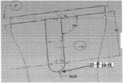
Fig. 3 representes to have the knee joint coronal plane that can be used in knee joint replacing process, revising the aligned exemplary excision otch of lower limb.As shown in the figure, select and/or the excision otch of design can comprise the different incisions on patient's the different piece of biological structure.For example, the excision otch facet on inboard and the lateral femur condyle can be non-coplane and parallel otch 1602,1602 ', the otch 1604/1604 ' that tilts perhaps not coplane and uneven otch 1602 and 1604 ' or otch 1602 ' and 1604.Similarly, the inboard of tibia and excision otch facet on the Outboard Sections can be not coplane and parallel otch 1606,1606 ', inclination and parallel otch 1608,1608 ' or not coplane and uneven otch 1606 and 1608 ' or otch 1606 ' and 1608.The not coplane facet of excision otch can comprise stairstepping otch 1610, so that connect not coplanar excision faceted surface.The excision size of selecting and/or designing can use the guiding tool (for example cutting clamper) of one or more selections and/or design to realize; The excision (for example guiding cutting tool) of guiding tool guiding patient biological structure is so that produce predetermined removal surface size (for example removal surface, angle and/or orientation).In some embodiments; That implants parts can be designed to include the one or more characteristics (for example bone groove surf zone, periphery, angle and/or orientation) with one or more excision otch or otch facet approximate match towards bone surface, and these excision otch or otch facet are by the predetermined aligning that strengthens the patient.As shown in Figure 3, some combinations of excision otch can help to make femur mechanical axis 1612 and tibia mechanical axis 1614 to aim at 1616.
Substitute or in addition, two on the plane of for example different implant thickness and/or wherein mechanical axis misalignment not some implant characteristics of the surface curvature on the homonymy also can help to revise limbs and aims at.Like following more complete description, independently tibia is implanted the parts and/or the inboard of tibia implantation parts and the independently tibia insert on the outside and can be used to strengthen the kneed aligning of patient.Implant parts and can in two or more parts of implant, comprise the thickness that increases gradually on constant but different thickness (the constant medial tibial land thickness that for example is different from constant lateral tibial land thickness), implant or the implant part, or constant and increase the combination of thickness gradually.
One or more distal femoral resection sizes, femur are implanted component thickness, femur implants parts surface curvature, tibial resection size, tibia implantation component thickness, tibia implantation parts insert thickness and/or tibia is implanted the selection of parts surface curvature and/or design can be used to regulate the femur mechanical axis and the tibia mechanical axis is aimed at (for example through changing the individual features on the sagittal plane, for example passing through with respect to corresponding rear side characteristic change front side characteristic) in the sagittal plane.In crown and the sagittal plane or the aligning in a plurality of planes of mechanical axis be out of shape can be through designing and/or selecting one or more excision sizes, one or more implantation component thickness and/or one or more implantation parts surface curvature to solve.
In some embodiments, design and/or selection can be designed or be chosen to comprise the exclusive or special characteristic of patient of additional patient to revise the aligned implantation parts of patient before the art.For example, implant or implant the roughly negative coupling of bone surface that can be designed and/or be chosen to and excise towards bone surface of parts.As shown in Figure 4, the periphery in two bone surfaces zone of patient's proximal tibia is different with regional 1910 for two different excision notch depths 1920.Similarly, Fig. 5 representes wherein to adopt two different distally views that excise the femur of otch.As shown in, the excision periphery that is used for two distally facets excision degree of depth is different for each medial condyle distally otch facet 1930 with lateral condyle distally otch facet 1940 with surf zone.
If the excision size for example tilts in coronal plane and/or sagittal plane; The various features towards bone surface of implanting the for example parts of parts can design according to the tilted alignment in entering joint and/or select, rather than according to vertical orientated design and/or selection.For example, according to the angle of otch, the tibia implant or implant parts excise the periphery that the periphery of tibia roughly just mating with the patient and have different shapes.Similarly, implant parts for femur, the distally condyle excision degree of depth or angle on inboard and/or the lateral condyle can be designed and/or be chosen to revise the aligned distortion of patient.But in this process, the one or more of angle of implant or implantation parts condyle width, length, curvature and impact tibia can change.Therefore, in some embodiments, one or more implants of implant periphery, condyle length, condyle width, curvature and angle or implant component feature for example with respect to tilting and/or not coplanar excision otch designs and/or selects.
Keep bone, cartilage or ligament
Traditional orthopaedic implants comprises bone groove.These bone grooves have been realized two purposes: they have made up the bone shape and their help that adapt to implant and have realized normal or approaching normal axis alignment.For example, bone groove can use to revise with the knee joint implant and turn in following or the articular surface of the bone that the distortion and being shaped of turning up matches to bone surface with the index plane of tradition implantation parts.For traditional implant, a plurality of bone grooves are set.Yet not using patient's proprietary information, these bone grooves because traditional implant finished product ground makes is the unique shapes of not considering the patient that preset for given implant.Therefore, the bone through the cutting patient to be cooperating with traditional implant, the bone that abandons than adopt specifically designed and/or selection to be used to handle the required situation of the implant of particular patients ' structure and defective many.
In some embodiments; A series of two dimensional images or the limbs aligning of three dimensional representation and expectation and/or the distortion correction of expectation based on patient joint anatomical structure and geometry; The excision otch is carried out optimization, so that be that each independent patient keeps maximum bone amount.Excision otch on two relative articular surfaces can be optimized to realize the minimum resected bone amount from one or two articular surface.
Through a series of two dimensional images on two relative articular surfaces regulating for example femoral head and acetabular bone, one or two condyle of femur and tibial plateau, coaster and patella, glenoid fossa and head of humerus, astragalus dome and tibial plateau, distally humerus and radius small end and/or ulna or radius and navicular bone or the excision otch in the three dimensional representation; Some embodiments allow patient's implant design personalized, that keep bone; This implant design can help suitable ligament balance and can help to avoid the joint " to overstuff ", has realized optimized bone reservation amount on the one or more articular surfaces in each patient simultaneously.
Implant design and modeling also can be used for realizing practicing thrift ligament, for example about PCL and/or ACL.Imaging test can be used to discern for example origin or beginning and/or the insertion section of the PCL on femur and tibia and ACL.Origin or beginning and insertion section can through adopt MRT or spiral CT arthrography direct observation for example ligament or be known as like the origin or beginning of the ligament of medial tibial sour jujube and lateral tibial sour jujube or the bone sign of insertion section through observation discern.
Implant system can then be selected based on view data or design, and make that for example femoral component keeps ACL and/or PCL origin or beginning, and tibial component keeps ACL and/or PCL appurtenance.Implant can be selected or design the bone groove that makes with ACL or PCL appurtenance or origin or beginning adjacency and can not weaken bone and cause potential fracture.
Keep for ACL, implant can have two single condyle tibial components that can utilize view data to select or design and place.Alternatively, implant can have front side bridge parts.Front side bridge parts can utilize imaging data and utilize known ACL especially and/or the PCL insertion section is selected or designed in the width on the dimension of front and back, its thickness or its length on inside and outside dimension on dimension up and down.
Shown in Fig. 6 A and 6B; The trailing edge of implantation parts that for example has polyethylene or a metal support holder of polyethylene insert can use imaging data or select and/or design from the shape that imaging data is derived; Make that implanting parts can not interfere with PCL, and keep the gap with PCL.This can be for example through in the concrete design of the quilt of implant or select or adjustment comprises recess in the profile of avoiding ligament and inserting and realizes.
The shape of any implantation parts can be selected and/or adjust, and makes itself and ligament structure keep the gap.Imaging data can help to discern or derive the shape or the positional information of this ligament structure.For example, the lateral femur condyle of single condyle, two condyle or whole knee joint system can comprise concavity or recess, to dodge tendon.At shoulder, glenoid component can comprise shape or the concavity or the recess of dodging tendon under the cartilage or biceps tendon.At hip, femoral component can be selected or be designed to dodge iliopsoas or adductor tendon.
Make up normal or approaching normal joint motion ability
In some embodiments, at least one that comprises implant can be designed or be chosen to realize normal joint motion ability towards bone surface or towards the bone groove and the implant shape of articular surface.
In some embodiments, can adopt the computer program of the biological activity in one or more joints of simulating knee joint for example or knee joint and ankle joint or hip, knee joint and/or ankle joint.In some embodiments, the exclusive imaging data of patient can be transfused to this computer program.For example, kneed a series of two dimensional images of patient or the kneed three dimensional representation of patient can be transfused to program.In addition, the two dimensional image of patient's ankle joint and/or hip joint or three dimensional representation can be added.
Randomly, other data that comprise the human body metric data can be added to each patient.These data can be including, but not limited to patient's age, sex, weight, highly, size, body-mass index and race.Desirable limbs are aimed at and/or distortion correction can be added in the model.The desired location of the implant area supported on the position of the bone groove on one or more articular surfaces and the one or more articular surface can be transfused to model.
Can derive the exclusive biological activity model of patient, comprise the above parameter combinations of enumerating.The biological activity model can be simulated the multiple activity of daily life, comprises normal paces, stair climbing, goes downstairs, runs, goes down on one's knees, squats, sits and any other physical behavio(u)r.The biological activity model can get down to the standardized behavior that is drawn by reference database usually.Can for example utilize radio frequency or optical markings and video equipment, utilize force plate and motion tracking device, utilize biological activity tolerance to generate these reference databases.
Then through using patient's proprietary information; Can make the biological activity model personalized; These information comprise at least one among patient age, sex, weight, height, body-mass index and the race but the limbs that are not limited thereto, expect are aimed at or distortion is revised and the imaging patients data, for example a series of two dimensional images or the three dimensional representation in the joint that will perform an operation of expection.
The implant shape that comprises the related bone otch that generates in the aforementioned optimization (for example correction, the reservation of the bone on one or more articular surfaces are aimed at, are out of shape to limbs) can be introduced in the model.The biological activity data that obtain can be used to further optimize the implant design, and its purpose is to make up normal or approaching normal mobility.The implant optimization can comprise one or more implantation parts.Based on comprising that the implant optimization based on the exclusive data of patient of the biological activity data of image can include but is not limited to:
● the coronal plane inside and outside is towards the joint implant shape variation
● the inside and outside, sagittal plane is towards the joint implant shape variation
● the axial plane inside and outside is towards the joint implant shape variation
● a plurality of planes or three-dimensional inside and outside are towards the joint implant shape variation
● inside face is to the bone implant shape variation in the coronal plane
● inside face is to the bone implant shape variation in the sagittal plane
● inside face is to the bone implant shape variation in the axial plane
● a plurality of planes or three-dimensional interior inside face are to the bone implant shape variation
● the for example relevant notch depth of one or more bone grooves, the variation of notch orientation
At least one articular surface or implant parts or a plurality of articular surface or said or all described any single or combination of implanting on the parts all are possible.
At a plurality of articular surfaces or implant when changing on the parts, these variations can be each other with reference to or make with being relative to each other.For example, in knee joint, the variation of the femur otch being made according to the exclusive biological activity data of patient can with the respective change of the lip-deep bone groove of relative tibia with reference to or relevant, if for example excise less femur, computer program selects to excise more tibia.
Similarly, if femur implant shape for example changes on outer surface, this possibly be accompanied by the change of tibial component shape so.For example when the part at least of tibia area supported and femur towards the negative coupling of articular surface the time, this is a particularly suitable.
Similarly, if the footprint of femur implant is widened, this possibly be accompanied by the broadening of area supported of tibial component so.Similarly, if tibia implant shape for example changes on outer surface, this possibly be accompanied by the change of femoral component shape so.For example when the part at least of femur area supported and tibia towards the negative coupling of articular surface the time, this is a particularly suitable.
Similarly, if the radius of patella parts is widened, this possibly be accompanied by widening of relative coaster area supported radius, and vice versa.
Similarly, in hip, if femur implant shape for example changes on outer surface, this can be accompanied by the change of acetabular bone component shape so.For example when the part at least of acetabular bone area supported and femur towards the roughly negative coupling of articular surface the time, this is a particularly suitable.For example, limbus of acetabulum can change via for example reaming or cutting.These surgeries change and the respective change on the cortical bone profile can virtual simulation, and derive and newly obtain circumferential edges.Peripheral Bone edge of deriving or shape can then be used for designing or select and the edge that changes or joint margins or the edge implant of part approximate match at least.
Similarly, in shoulder, if glenoid fossa implant shape for example changes on outer surface, this can be accompanied by the change of the shape of humeral component.For example when the part at least of humerus area supported with glenoid during towards the roughly negative coupling of articular surface, this is a particularly suitable, perhaps vice versa.
Through optimization implant shape in this way, can make up normal or near normal mobility.In addition, can avoid and implant relevant complication, including, but not limited to preceding fluting, nest impact, the impact of back femoral component in high flexing process and with other relevant complication of existing implant design.
The biological activity model that is used for particular patients ' can be augmented with the exclusive data of patient and/or finite element modeling or other biological mechanistic model known in the art.The power that obtains in can each component computes knee joint for each particular patient.Can require implant is designed according to patient's load and power.For example, 125 pounds of patients maybe not need as 280 pounds of tibial plateaus that the patient is so thick.Similarly, can adjust poly shape, thickness and material behavior to every patient.For example, 3mm polyethylene insert can be used for patient in light weight and that strength is little, and patient heavier or that carry out more multi-activity possibly need 8mm polyethylene insert or similar devices.
Complicated modeling
As the described herein, some embodiments can Application Modeling, for example; Virtual modeling and/or mathematical modeling; Confirming best implanting component feature and metric, and randomly confirm excision characteristic and metric, to realize or to improve one or more parameter objectives or threshold value.For example; With respect to the parameter of implanting parameter that parts select and randomly selecting to corresponding excision otch and/or guiding tool, the model of patient joint or limbs can be used for confirming, select and/or design one or more best features and/or characteristic measure value.In some embodiments, doctor, clinician or other user can be selected one or more parameters, parameter threshold or target and/or be used for the relative weighted number of the parameter that model comprises.Substitute or in addition, the data when clinical data that for example from clinical trial, obtains or operation take place can be included in to be selected parameter objectives value or threshold value and/or confirms in best features and/or the characteristic measure value for implanting parts, excision otch and/or guiding tool.
One or more parameters of more than describing and/or any combination of one or more additional parameters can be used for adapting to patient (for example the patient is exclusive and/or patient special) and implant the design of parts and/or select; And in some embodiments, be used for adapting to accordingly patient's excision otch and/or adapt to the patient guiding tool design and/or select.In specific assessment, patient's biological characteristic and characteristic measure value can be used to select and/or design one or more implantation component features and characteristic measure value, excision cut-out feature and characteristic measure value and/or guiding tool characteristic and characteristic measure value.
The optimization of joint motion ability can be used as another parameter comprise postoperative not the movable joint line reduce any motion of joint line or reduce any threshold value or excision numerical value so that in the purpose of upside or downside movable joint line.The optimization of joint motion ability also can comprise tough bringing onto load or the function in the motor process.
As the described herein, the bone groove of the implant of various sizes, shape, curvature and thickness and all kinds, position, orientation and quantity can be selected and/or design and make.Implant design and/or implant parts and can from the storehouse, select, enroll in the storehouse and/or be stored in the storehouse.The storehouse can be implant or parts, maybe can combine and/or change the virtual library with the component feature that forms final implant.The storehouse can comprise the catalogue of physics implantation parts.In some embodiments, can utilize storehouse identification and selection physics to implant parts.The storehouse can comprise the implantation parts of the previous generation with one or more adaptation patient characteristics and/or have and can be changed with the standard that adapts to the patient or the parts of blank characteristic.Therefore, implant and/or implantation parts can be selected from the storehouse.
Therefore, in some embodiments, implant can comprise characteristic and one or more characteristic of from source, one or more storehouse, selecting of the exclusive design of one or more patients.For example, in the implant that is designed for the whole knee joint replacing that comprises femoral component and tibial component, parts can comprise the exclusive characteristic of one or more patients, and another parts can be selected from the storehouse.Table 4 comprises the exemplary lists that possibly make up.
Table 4: exclusive parts of patient and derive the example combinations of parts from the storehouse
Figure BPA00001482259800381
In some embodiments, before the needs of patients joint implant, the storehouse can generate, to comprise the image of the particular patient that comes from one or more ages.For example, a kind of method can comprise that identification has the patient of risk factor of one or more joints problem, and for example the bmd score value is low, and with one or more image collection in patient joint in the storehouse.In some embodiments, can scan all patients (the for example patient of all below 40 years old) below the dating, thereby collect one or more images in patient joint.Can deposit or be stored in the exclusive data base of patient from image and data that the patient collects.For example, the joint shape in one or more joints of patient can be stored in the electronic databank, up to the needs of patients implant.Then, image and data in the exclusive data base of patient can be visited, and can use the original anatomical structure of the patient who not influenced by joint deformity to generate the part or all of joint replacement implants that the patient is exclusive and/or the patient is special.The result of this process has more functional and the implant of anatomical fit more.
Tibia is implanted component feature
In the numerous embodiments of here describing, one or more characteristics that tibia is implanted parts are designed and/or select, and randomly combine with implantation process, make tibia implant parts and patient's coupling.For example; In some embodiments; According to the exclusive data of patient, one or more characteristics that tibia is implanted parts and/or implantation process are designed and/or select, and make tibia implant parts and mate (for example roughly bear and mate and/or roughly just mate) basically with one or more patient's biological structures.Substitute or in addition, tibia is implanted one or more characteristics of parts and/or implantation process can come specialization before the art according to the exclusive data of patient, so that for the patient best fit is provided with respect to one or more parameters (for example one or more said parameter).For example, in some embodiments, keep tibia and implant the special catabolic bone of parts and can design and/or select according to one or more patients joint size of seeing on a series of two dimensional images that generate by for example CT scan or MRI scanning or the three dimensional representation.Substitute or in addition, special catabolic tibia is implanted parts and can at least partly be designed and/or select, so that implant the composition surface of parts provides the best for cooperation from the patient to articular surface with respect to respective femur.
Some embodiments comprise and have one or more adaptation patients that the tibia of (for example the patient is exclusive or patient special) characteristic and optional one or more standard features implants parts.Randomly, one or more adaptation patient characteristics can be designed and/or select to cooperate patient's quilt excision tibia surface.For example; According to patient's the anatomical structure and the postoperative geometry or the aligning of hope; Patient's the outside and/or medial tibial platform can be by independent excisions and/or for example with the different depth excision, the surface that makes the quilt of outside platform excise be higher than (for example high 1mm, greater than 1mm, 2mm and/or greater than 2mm) or be lower than (for example low 1mm, greater than 1mm, 2mm and/or greater than 2mm) medial tibial platform by removal surface.
Therefore, in some embodiments, tibia is implanted parts can come independent design and/or selection to each outside and/or medial tibial platform.For example, but periphery independent design and/or selection that the periphery that lateral tibial is implanted parts and medial tibial are implanted parts so that with each outside and the medial tibial platform by the peripheral approximate match of removal surface.Fig. 7 A and 7B represent the inboard and lateral tibial implantation parts of exemplary single condyle, do not have polyethylene layer or insert (Fig. 7 A) and have polyethylene layer or insert (Fig. 7 B).As shown in, lateral tibial is implanted parts and is implanted parts with medial tibial and have different peripheral shapes, each peripheral shape and accordingly by the peripheral approximate match of removal surface (seeing arrow).In addition, being used for lateral tibial implants polyethylene layer or the insert 6010 that parts and medial tibial implant parts and has the peripheral shape corresponding to corresponding implantation parts peripheral shape.In some embodiments, one or both implant parts can process (rather than having polyethylene layer or insert) by plastics or polyethylene fully, and each whole implantation parts can comprise the peripheral shape with the peripheral approximate match of corresponding removal surface.
In addition, but lateral tibial is implanted the height and the inboard height independent design and/or the selection of implanting parts of parts, so that keep or change the relative altitude of the different removal surfaces generations of each outside and medial tibial platform.For example; Lateral tibial is implanted parts can implant parts thick (for example thick 1mm, greater than 1mm, 2mm and/or greater than 2mm) or thin (for example thin 1mm, greater than 1mm, 2mm and/or greater than 2mm) than medial tibial, so that keep or change the relative altitude towards articular surface of each outside and medial tibial implantation parts as required.Shown in Fig. 7 A and 7B, the relative altitude 6020 on the outside and medial resection surface uses the outside with same thickness to keep with the inboard parts (and the outside and inboard polyethylene layer or insert) of implanting.Alternatively, outside implantation parts (and/or outside polyethylene layer or insert) can have the thickness that is different from inboard implantation parts (and/or inboard polyethylene layer or insert).Implant one or two embodiments processed by plastics or polyethylene (rather than having polyethylene layer or insert) fully in the parts for inboard and the outside, a thickness of implanting parts can be different from the thickness that another implants parts.
Different inboards and lateral tibial cut height are also implanted parts applicable to single-piece, and for example integrally formed tibia is implanted parts.In this case, the corresponding of tibia implantation parts and patient's femur can be had inclined surface or the stairstepping otch that is connected inboard and outer surface facet by removal surface.For example, Fig. 8 A-8C is described in three kinds of dissimilar stairstepping otch 6110 that on patient's proximal tibia inboard and lateral resection otch facet separated.In some embodiments, tibia is implanted being selected and/or designing towards bone surface of parts, so as with these case depths and stairstepping otch angle and for example other optional feature of peripheral shape mate.
Tibial component also can comprise identical inboard and outside cut height.
In some embodiments, medial tibial platform facet can be different from the angular orientation of lateral tibial platform facet, perhaps can the equal angular orientation.On the exclusive angle of one or two be in patient in the inboard and lateral tibial platform facet, for example in the sagittal plane, be similar to the one or more original slope of inboard and/or lateral tibial platform.In addition, interior sidelead can be that the patient is exclusive, and outer sidelead can be fixing or predetermined, and perhaps vice versa, as shown in table 5.
Table 5: the exemplary design of tibia slope
Figure BPA00001482259800411
Example combinations shown in the table 5 is applicable to the implant of using two single condyle tibias that have or do not have metal gasket to implant parts (inboard and an outside).They are also applicable to using single tibia to implant the implant system of parts; Single tibia is implanted parts and is comprised the all-plastic design or pass through insert (randomly; Single insert for inboard and outside platform; Perhaps two inserts, for example an inboard and an outside) be lined with the design of metal, for example PCL maintenance, posterior stabilisation or ACL and PCL keep implanting parts.Slope preferably between the 0-7 degree, still can use other embodiment with other slope angle outside this scope.Slope can change from the front side to rear side on one or two tibia facet.For example, less slope can be used in the front side, 0-1 degree for example, and rear side uses bigger slope, for example 4-5 degree.Variable slope in inboard or the lateral tibial facet at least one can be through for example using grinding tool (for example through robot guiding) or through using the two or more bone grooves at least one tibia facet to realize.In some embodiments, can use two independent slopes in inboard and the outside.Independently the design of tibia slope can be used to realize the reservation of bone.In addition, independent slope design can help realizing the implant mobility of also more approaching more naturally normal knee joint or patient's knee joint function.
In some embodiments, slope can be fixed, and for example internal fixation is spent 3,5 or 7 in the sagittal plane.In some embodiments, the inboard or the outside or both slopes can be that the patient is exclusive.Patient's interior sidelead can be used to derive single or two-piece type tibia and implants medial tibial parts slope and optional outside parts slope in the parts.Patient's outer sidelead can be used to derive single or two-piece type tibia and implants lateral tibial parts slope and optional inner part slope in the parts.Patient's slope is usually between the 0-7 degree.Under situation about selecting, the patient can show the inboard or outer sidelead greater than 7 degree.In this case, if patient's interior sidelead has greater than other pre-selected threshold of high value or some of 7 degree, patient's outer sidelead can be applicable to medial tibial and implants the inboard that parts or single-piece tibia are implanted parts.If patient's outer sidelead has greater than other pre-selected threshold of high value or some of 7 degree, patient's interior sidelead is implanted the outside that parts or single-piece tibia are implanted parts applicable to lateral tibial.Alternatively, if patient's the inboard or the outside one or the slope on both surpass pre-selected threshold, for example 7 degree or 8 degree or 10 degree, fixed slope can be applicable to inner part or inboard, be applied to outside parts or the outside or both.Fixed slope can equal threshold value, and for example 7 degree perhaps can be different numerical.Fig. 9 A and 9B represent to derive tibia and implant the medial tibial parts slope (Fig. 9 A) of parts and/or the exemplary process diagram of lateral tibial parts slope (Fig. 9 B).
The fixed tibial slope can be used for any embodiment described herein.
In another embodiment, mathematical function can be used to derive inboard implant slope and/or outside implant slope or both (wherein both can be identical).In some embodiments, mathematical function can comprise from a series of two dimensional images of for example CT scan or MRI scanning generation or the metric of one or more patients joint size derivation that three dimensional representation is seen.For example, mathematical function can comprise the degree of geometrical value of patient's femur and the ratio between patient's tibia slope.Substitute or in addition, mathematical function can be or comprise the patient's tibia slope divided by fixed numbers.In some embodiments, mathematical function can comprise the metric that the corresponding implantation parts (for example femur implantation parts) from the patient are derived, and implants parts itself and can comprise that the patient is exclusive, the patient is special and/or the characteristic of standard.Those of ordinary skill in the art can adopt and use mathematical function to derive the many different probabilities of patient's slope.
In some embodiments, inboard and lateral tibial platform can the equal angular excision.For example, single excision otch or identical a plurality of excision otch can use on two platforms.In other embodiments, the angle that inboard and lateral tibial platform can be different is excised.A plurality of excision otch can use when and lateral tibial platform inboard with the different angles excision.Randomly, inboard and lateral tibial can also be excised with different distance with respect to tibial plateau.In this case, inboard can have different slopes with two horizontal plane tibia otch in the outside, and/or be attended by usually at inboard one or two vertical or the tilt excision otch placed of tibial plateau parts.Fig. 3 and Fig. 8 A-8C have represented a plurality of exemplary tibial resection otch of any combination use that can be through inboard and outside platform.
Medial tibial is implanted the parts platform can have smooth, protrusion, recessed or disc-shaped surface, and/or it can have and is different from the thickness that lateral tibial is implanted the parts platform.Lateral tibial is implanted the parts platform can have smooth, protrusion, recessed or disc-shaped surface, and/or it can have and is different from the thickness that medial tibial is implanted the parts platform.Different thickness can use material different thickness to realize, for example metal thickness on the either side or polyethylene or insert thickness.In some embodiments, the outside and inner surface are selected and/or design, and make its very similar patient's anatomical structure of suffering from before the arthritis.
Inboard and/or lateral tibial implant the parts platform (for example have only metal, have only pottery, be lined with polyethylene or other insert metal, have the configuration of single or two insert and list or double bracket) height can for example use imaging test to confirm according to patient's tibia shape.
Alternatively, inboard and/or lateral tibial parts platform (for example have only metal, have only pottery, be lined with polyethylene or other insert metal, have the configuration of single or two insert and list or double bracket) height can confirm according to patient's femur shape.For example; If patient's lateral condyle has the radius less than medial condyle; And/or being positioned at upside more than medial condyle with respect to its area supported, the height of tibial component platform can be regulated and/or select so, to guarantee the best joint motions with the femur area supported.In this example, the height of lateral tibial parts platform can be regulated and/or select, and makes it be higher than the height of medial tibial parts platform.Because polyethylene is directly not visible on standard x ray usually; Metal or other labelling can randomly be included in the insert; So that the position of indication insert or height, particularly when use has one or more asymmetric inboard and the outside insert of different inboard and thickness as outside.
Alternatively; Inboard and/or lateral tibial parts platform (for example have only metal, have only pottery, be lined with polyethylene or other insert metal, have the configuration of single or two insert and list or double bracket) height can confirm that the shape of for example implanting some characteristics of parts according to patient's femur is confirmed according to the shape of corresponding implantation parts.For example; If implanting parts, femur comprises having less than the radius of medial condyle and/or be positioned at the lateral condyle of upside more than medial condyle with respect to its area supported; The height of tibia implantation parts platform can be regulated and/or select so, to guarantee to implant with femur the best joint motions of the area supported of parts.In this example, lateral tibial is implanted the height of parts platform can regulate and/or be chosen to be higher than the height that medial tibial is implanted the parts platform.
In addition, the for example interior outside of tibia insert or front and back side curvature or both surface configurations can reflect the shape of femoral component.For example, inboard insert shape can with the one or more radiuses couplings on the medial femoral condyle of femoral component.Outside insert shape can with the one or more radiuses couplings on the lateral femur condyle of femoral component.Outside insert also can randomly mate with medial condyle.Coupling is for example being carried out in the coronal plane.This helps the optimization of wearing and tearing.Prefabricated insert can select to be used for medial tibial, its in coronal plane with the pre-selected proportion and the medial femoral condyle radius coupling of for example 1: 5 or 1: 7 or 1: 10.Any combination also is fine.Prefabricated insert can select to be used for lateral tibial, its in coronal plane with the pre-selected proportion and the lateral femur condyle radius coupling of for example 1: 5 or 1: 7 or 1: 10.Any combination also is fine.Alternatively, outside insert also can mate with medial condyle, and perhaps inboard insert shape also can be mated with lateral condyle.These combinations also are fine for the single insert system with metal gasket and two insert systems.One of skill in the art will recognize that these couplings also applicable to the implant of using complete poly tibial component, the radius on the for example complete poly tibial component can mate with the femur radius in a similar fashion.
The coupling of radius also can appear in the sagittal plane.For example, sickle can be used at the tibia insert or cuts out in the polyethylene tibia fully and femur implant or patient's geometric match or the fixing crown curvature that therefrom derives.The path that sickle adopted and/or the degree of depth can be according to femur implant geometries or according to surgical operation patient's femur geometry derivation before.Inboard on tibia insert or the complete polymer tibia can be identical with outside sagittal geometry.Alternatively, each can cut separately.Through regulating according to the sagittal geometry of femoral component or condyle of femur or mating tibia polymer geometry, can realize better function result.For example, can realize more physiology shin femur motion and mobility.
Inboard and/or outside parts can comprise groove.Inner part can be a dish type, and outside parts comprise groove.Outside parts can be dish types, and inner part comprises groove.Outside parts can protrude, and inner part comprises groove.The shape of inboard or outside parts can derive according to the patient on one dimension, two dimension or three-dimensional or mate with the patient, and for example this is relevant with its periphery and surface configuration thereof.The protrusion shape of outside parts derives according to the patient on one dimension, two dimension or three-dimensional or matees with the patient.Groove can be straight.Groove also can be crooked.The curvature of groove can have constant radius of curvature, perhaps can comprise a plurality of radius of curvature.Radius can be for example derived according to femur geometry or patient's mobility and patient's coupling or from the patient.These designs go for single-piece tibia polyethylene or other plastic insertion pieces, perhaps are applicable to two-piece type tibia polyethylene or other plastic insertion pieces.The example combinations of the tibia holder design of Figure 10 A-10D representes to have two inserts (Figure 10 A-10O) and single insert (Figure 10 P-AD), it has different inboards and outer surface shape.
Single type or two-piece type tibia insert
In a preferred embodiment, the holder parts can receive single type insert or two-piece type insert.The two-piece type insert can be the single type insert that is cut to two halves in the roughly medial-lateral midpoint of insert.This can form inboard insert and the outside insert that has all characteristics of describing in the single type insert described herein separately.Alternatively, every can separately form, and has the different surface shape, and different locking mechanisms.Be superior to the single type insert and use an advantage of two-piece type insert to be and to use different thickness to each inboard insert and outside insert, to adapt to the concrete geometry in the concrete joint of patient.Therefore, for example through on a side, selecting to compare thicker parts with opposite side, the surgeon can be in art optimization ligament balance or soft tissue balance.In addition, the surgeon can select to have differently contoured part in art, and this can help the mobility in joint, and also can help ligament or soft tissue balance.For example, inboard insert can have roughly recessed shape.Outside insert can have the protrusion shape.Alternatively, outside insert can have concave shape on inboard lateral direction, and upwards is straight in front and back.Alternatively, outside insert can have concave shape on inboard lateral direction, at the profile of following the normal sliding path of the lateral condyle on the lateral tibial platform on the AP direction.Similarly, inboard insert can have roughly recessed shape on inboard lateral direction, at the profile of following the normal sliding path of the medial condyle on the medial tibial platform on the AP direction.Randomly, one or two insert can be put down.
Be to have the inboard of two inserts and the example (table 6) that possibly make up of outside insert below:
Table 6: the example (in addition shown in Figure 10 A-100) of possible inboard and the combination of outside two-piece type insert:
Insert thickness Inboard The outside
Inboard thickness=thickness as outside Recessed Protrusion
Inboard thickness=thickness as outside Recessed Smooth
Inboard thickness=thickness as outside Recessed Recessed
Inboard thickness=thickness as outside Smooth Protrusion
Inboard thickness=thickness as outside Smooth Smooth
Inboard thickness=thickness as outside Smooth Recessed
Inboard thickness=thickness as outside Protrusion Protrusion
Inboard thickness=thickness as outside Protrusion Smooth
Inboard thickness=thickness as outside Protrusion Recessed
Inboard thickness is less than thickness as outside Recessed Protrusion
Inboard thickness is less than thickness as outside Recessed Smooth
Inboard thickness is less than thickness as outside Recessed Recessed
Inboard thickness is less than thickness as outside Smooth Protrusion
Inboard thickness is less than thickness as outside Smooth Smooth
Inboard thickness is less than thickness as outside Smooth Recessed
Inboard thickness is less than thickness as outside Protrusion Protrusion
Inboard thickness is less than thickness as outside Protrusion Smooth
Inboard thickness is less than thickness as outside Protrusion Recessed
Inboard thickness is greater than thickness as outside Recessed Protrusion
Inboard thickness is greater than thickness as outside Recessed Smooth
Inboard thickness is greater than thickness as outside Recessed Recessed
Inboard thickness is greater than thickness as outside Smooth Protrusion
Inboard thickness is greater than thickness as outside Smooth Smooth
Inboard thickness is greater than thickness as outside Smooth Recessed
Inboard thickness is greater than thickness as outside Protrusion Protrusion
Inboard thickness is greater than thickness as outside Protrusion Smooth
Inboard thickness is greater than thickness as outside Protrusion Recessed
Identical surface profile or similar surface profile can be used for the single-piece insert.Be to have the inboard of single-piece tibia insert and the example (table 7) that possibly make up of outside implant surface profile below:
Table 7: have the possibility inboard of single-piece tibia insert and the example (in addition shown in Figure 10 P-AD) of outside implant surface profile:
Insert thickness Inboard The outside
Inboard thickness=thickness as outside Recessed Protrusion
Inboard thickness=thickness as outside Recessed Smooth
Inboard thickness=thickness as outside Recessed Recessed
Inboard thickness=thickness as outside Smooth Protrusion
Inboard thickness=thickness as outside Smooth Smooth
Inboard thickness=thickness as outside Smooth Recessed
Inboard thickness=thickness as outside Protrusion Protrusion
Inboard thickness=thickness as outside Protrusion Smooth
Inboard thickness=thickness as outside Protrusion Recessed
Inboard thickness is less than thickness as outside Recessed Protrusion
Inboard thickness is less than thickness as outside Recessed Smooth
Inboard thickness is less than thickness as outside Recessed Recessed
Inboard thickness is less than thickness as outside Smooth Protrusion
Inboard thickness is less than thickness as outside Smooth Smooth
Inboard thickness is less than thickness as outside Smooth Recessed
Inboard thickness is less than thickness as outside Protrusion Protrusion
Inboard thickness is less than thickness as outside Protrusion Smooth
Inboard thickness is less than thickness as outside Protrusion Recessed
Inboard thickness is greater than thickness as outside Recessed Protrusion
Inboard thickness is greater than thickness as outside Recessed Smooth
Inboard thickness is greater than thickness as outside Recessed Recessed
Inboard thickness is greater than thickness as outside Smooth Protrusion
Inboard thickness is greater than thickness as outside Smooth Smooth
Inboard thickness is greater than thickness as outside Smooth Recessed
Inboard thickness is greater than thickness as outside Protrusion Protrusion
Inboard thickness is greater than thickness as outside Protrusion Smooth
Inboard thickness is greater than thickness as outside Protrusion Recessed
With reference to figure 11A-11C, the inboard can be estimated according to the demographic data that comprises relevant age, sex, race, body wt, BMI and other consensus datas with outside sliding path.Alternatively, the outside and inner slide path can be estimated according to the mobility modeling.The mobility modeling also can be based on the data base's.The mobility modeling can comprise introduces the exclusive data of patient, for example age, sex, race, body wt, BMI and other consensus datas and the exclusive anatomical structure of patient or the geometry that for example from imaging test, derive.In some embodiments, at least one inboard or lateral tibial implant profile or both can be conditioned, and make crown curvature (for example protrusion or recessed) at least partly follow sliding path.
Notice that above a plurality of embodiments have been described the implant system that uses the metal that is lined with single-piece or two part plastic insertion pieces.The combination of similar face profile shown in the table 6 and 7 and thickness is applicable to there not being metal substrate but have the tibia implant of the attachment means that is attached to its base portion.This tibia implant system can comprise and comprises poly plastics and pottery or synthetic or its combination; They can comprise the parts that replace whole tibial plateau, perhaps the combination of the single condyle tibial component in the inboard and the outside.
Surface profile can be derived or the adaptation patient from the patient.For example, the sagittal radius of tibial component can be that the patient is exclusive, for example derives according to patient's subchondral bone at least a portion of femoral component or cartilage shape.The crown radius of femoral component can be special.The tibial component that cooperates can at least partly comprise from the exclusive femoral component radius of said patient derives the sagittal radius of (for example broadening slightly) and the crown radius of specialization of deriving and preferably broadening slightly with respect to the crown radius of said specialization femur from the crown radius of said specialization femur.Any combination of exclusive and special catabolic femur of patient and tibia radius all is fine.Similarly, patient's any being combined in other joints exclusive and specialization radius also is fine.
The attendant advantages that the two-piece type insert is superior to the single type insert is easy to use.Because the size of insert and the limited space property in joint are difficult to be placed in the knee joint in the common orthopaedic surgical operations operation process of single type insert.Every of the two-piece type insert not only size and, the outside of insert or inboard at first are inserted in the joint less than whole single type insert according to the size limitations in joint.
The free-revving engine of arthroplasty is different attitude angle balance soft tissues and the ligament for the joint.In knee joint, this balance can realize with stretching by gentle song for knee joint in various degree.The surgeon has the multiple choices that can be used in soft tissue and ligament balance.These selections for example comprise: the placement of bone groove is selected in (1), comprises height, the degree of depth and the orientation (for example tibia slope) of bone groove, so that soft tissue and ligament balance are best; (2) select removing of hyperosteogeny; And/or (3) soft tissue discharges the for example release of MCL or lateral collateral ligament with local or whole ligament.But in case these steps are implemented, the surgeon does not have the measure of further optimization ligament or soft tissue balance usually on hand.Therefore, if the knee joint situation loose excessively, the measure that the surgeon does not revise through traditional knee joint implant in gentle song or stretching process, occur in one or both sides.Therefore, in some embodiments, the surgeon is provided multiple different single-piece insert system.Every has different thickness and/or inboard or outer surface profile.The insert system can be attended by matching test spare, and test block can insert locking system and remove easily.The surgeon can test different insert systems with stretching by gentle song to knee joint in various degree, so that it is uneven to revise any remaining ligament.
In some embodiments, the surgeon can use the system of two inserts.Each insert (inboard and the outside) can be provided with different-thickness and/or different implant profile.The inboard and the outside insert system of test can be provided, and it can insert metal substrate and locking, and can after test, remove from lock-out state easily.The surgeon can test the various combination of inboard and outside insert system, and can be through selecting to optimize ligament and soft tissue balance to different gentle songs and the inboard of stretching angle generation optimum balance result and the combination of outside insert.
All embodiments described herein are compatible with tibial component, and wherein (1) keeps front side and rear side ligamentum cruciatum; (2) only keep the rear side ligamentum cruciatum; Perhaps (3) are by posterior stabilisation (promptly removing two ligamentum cruciatums).
Ligament keeps
With reference to figure 6A-6B, 12 and 13A-13B, the expression ligament keeps the example of tibia implant.For example, implant can provide knee joint space ligament, and rear side ligamentum cruciatum (PCL) for example, and make that parts are able to be shaped is interfered with ligament avoiding.Randomly, the origin or beginning of PCL and insertion section can be discerned in the imaging research of for example ultrasonic, CT scan, MRI scanning, photoscanning, laser scanning, photoacoustic imaging or alternate manner.PCL origin or beginning and insertion section and proper ligament can for example directly be discerned in imaging research when using MRI.Alternatively, origin or beginning and/or insertion section can be discerned through the bone sign of the groove on definite for example tibia rear side, this attached position of sign expression bone.In this way, the tibia holder can be formed, thereby dodges ligament, and can after operation, be kept perfectly.For example, for example metal gasket or insert or both or fully the tibia holder of polymerization parts can be shaped as comprise recessed and with respect to the PCL insertion section than the wide slightly groove of PCL and insertion section thereof.
In addition, the tibia holder can be configured or select, and to consider front side ligamentum cruciatum (ACL), makes that parts are able to be shaped, and interferes with ligament avoiding.Randomly, ACL origin or beginning and insertion section can be discerned in the imaging research of for example ultrasonic, CT scan, MRI scanning, photoscanning, laser scanning, photoacoustic imaging or alternate manner.ACL origin or beginning and insertion section and proper ligament can for example directly be discerned in imaging research when using MRI.The bone sign of the irregular portion that alternatively, origin or beginning and/or insertion section can be through confirming groove or bone on femur or the tibia is confirmed this attached position of sign expression bone.In this way, the tibia holder can be formed, thereby dodges ligament, and can after operation, be kept perfectly.Therefore, embodiment described herein makes tibia implant parts and is able to shapings/design and/or selection, adapting to patient's anatomical structure, thereby avoids any interference with ligament, and keeps these ligaments.This is applicable to the system of single part or two parts, and it has metal gasket or does not have metal gasket.
In addition, tibia and femoral component can be formed, and for example use imaging data to avoid any soft tissue to interfere.Other soft tissue structure or the bone label relevant with these soft tissue structures can for example be discerned according to patient's imaging data.For example, with reference to figure 14A-14B, in knee joint, can discern tendon, inboard utricule, outside utricule, rear side utricule, fat pad, pleat and other soft tissue structures of method suddenly.Femur and/or tibia are implanted parts and can be designed, be shaped or select, make its avoid with these or other soft tissue structure in one or more interference or impact.
The joint can move to different attitude angles virtually, comprises the mobility simulation, so that detect any potential ligament or soft tissue interference or impact.Implanting parts can be designed or regulate, so as in various degree gentle song and stretching, extension, abduction and interior receipts, raise, rotate and/or other positions, avoid ligament or soft tissue to interfere or impact.
Similarly, in hip, femur and acetabular bone parts can be formed, and for example use imaging data to avoid any soft tissue to interfere.Other soft tissue structure or the bone label relevant with these soft tissue structures can for example be discerned according to patient's imaging data.For example, can discern inboard utricule, outside utricule, rear side utricule, front side utricule, iliopsoas tendon and other soft tissue structures.Femur and/or acetabular bone are implanted parts and can be designed, be shaped or select, make its avoid with these or other soft tissue structure in one or more interference or impact.
Similarly, in shoulder, humerus and glenoid component can be formed, and for example use imaging data to avoid any soft tissue to interfere.Other soft tissue structure or the bone label relevant with these soft tissue structures can for example be discerned according to patient's imaging data.For example, can discern inboard utricule, outside utricule, rear side utricule, front side utricule, the rotator cuff that comprises tendon of supraspinatus muscle, tendon of infraspinatus muscle, teres minor and subscapularis and other soft tissue structures.Humerus and/or glenoid fossa are implanted parts and can be designed, be shaped or select, make its avoid with these or other soft tissue structure in one or more interference or impact.
Can adopt several different methods to design cross and keep implant.For example, Figure 15 A-15C describes the illustrative methods that a kind of PCL of design keeps ligament.In Figure 15 A, tibia implant periphery designs according to the peripheral shape on the tibia surface of plan excision.In Figure 15 B, the design of implant periphery is changed, and makes that PCL is able to keep.Figure 15 C representes that PCL keeps tibia to implant the gained shape of parts, and wherein PCL is expressed as circle.
Cross substitutes
Except described implantation component feature, some embodiments can comprise and are used for alternate characteristic of cross and design.These characteristics and design can for example comprise Os Draconis, post or implant stretching out and engage the protuberance that housing between corresponding condyle, holder or respective femur are implanted the bar on the parts towards bone surface of parts from tibia.Figure 16 A-16C has described and has comprised that stablizing fin implants parts with the tibia that helps to stablize cross removal knee replacement.
Figure 17 A and 17B have described the example cross section that the tibia with the post (or Os Draconis or protuberance) that stretches out from the surface of implanting parts is implanted parts.Particularly, Figure 17 A representes that (a) has the tibia implantation parts of right cylinder or protuberance, and (b)-(d) has outer side positioning and have the post of variable thickness, length and curvature or the tibia implantation parts of protuberance.Figure 17 B representes that (a)-(e) has interior side positioning and have the post of variable thickness, length and curvature or the tibia implantation parts of protuberance.
Shown in accompanying drawing, the upper surface of holder parts have be configured to and the recessed surface of the condyle of femur surface engagement of femur implant between " keel type " structure.This " keel type " structure can be formed at interior slip of groove of femur implant.Groove can comprise that each end that is positioned at groove sentences the shut-down mechanism that " keel type " structure is remained on the track of groove.This " keel type " structure and groove dispose the rear side ligamentum cruciatum that can be used for the patient was removed and need carries out implant at intraarticular posterior stabilisation as the part of surgical procedures situation.
In some embodiments, tibia is implanted parts and can be designed and manufactured as post or the protuberance that comprises as the permanent integrated characteristic of implanting parts.But in some embodiments, post or protuberance can be modular.For example, post or protuberance can be implanted parts with tibia and separate design and/or manufacturing, and randomly before implantation process, combine with these parts in (for example before the art) or the implantation process.For example; Modular post or protuberance and tibia are implanted parts and can be used integrated mechanism to cooperate, and integrated mechanism for example is that corresponding convex thread and recessed screw thread, other convex or female locking mechanism maybe can be integrally formed other mechanism that tibia is implanted in the parts or gone up and in the normal wear process, provide for post or protuberance stability with post or protuberance.Modularity post or protuberance can the orthopaedic surgical operations doctor or doctor's selection under for example be attached to tibia on the unlapped integrated mechanism and implant parts through removing the connector that covers integrated mechanism or other device and modularity post or protuberance being attached to.
Post or protuberance can comprise the characteristic that adapts to patient (for example the patient is exclusive or patient special).In some embodiments, post or protuberance comprise according to comprising design before the exclusive data art of patient of imaging data and/or one or more characteristics of selecting, so as with one or more patient's biological characteristic approximate match.For example, the length of one or more parts of post or protuberance, width, height and/or curvature can be for example with respect to patient's intercondylar distance or the degree of depth, femur shape and/or condyle shaped design and/or to be chosen to the patient exclusive.Substitute or in addition, one or more characteristics of post or protuberance can be come specialization according to the exclusive data of patient, to offer patient's best fit.For example, the length of one or more parts of post or protuberance, width, height and/or curvature can be designed and/or to be chosen to patient spy catabolic.One or more thickness of housing, holder or bar can be exclusive with the patient metrics match.One or more sizes of post or protuberance can be regulated according to one or more implant sizes (for example respective femur is implanted one or more sizes of housing, holder or bar on the parts), and these sizes can be that the patient is exclusive, specialization of patient or standard.One or more sizes of post or protuberance can be according to patient's weight, highly, sex and body-mass index regulate.In addition, one or more characteristics of post or protuberance can be standards.
Randomly, with reference to figure 17A and 17B, exemplary " keel type " structure or post can be regulated according to patient's anatomical structure.For example, post can be formed, and makes femur more normal with respect to the physiology sliding path of tibia.Therefore, post can extend to from its base portion its when most advanced and sophisticated to the inside or outside skew.This inboard or outside skew can be designed to realize kneed near physiology rolling and rotation action.The inboard of post and outside curve can be regulated according to the exclusive imaging data of patient.For example, the interior outside of post or Os Draconis gentle bent or crooked can the coupling (for example with the physics of PCL or ACL or the direction coupling of power) from patient's derivation or with the patient.Substitute or in addition, post or Os Draconis can specific AP angle or crooked skews, and for example the sagittal curve of post or Os Draconis can be the reflection of the PCL position and the combination of orientation or ACL and PCL position and orientation.Post is convergent randomly, perhaps has different diameters and cross section profile at the differing heights place of leaving its base portion, for example circular, oval, avette, square, rectangle.
The different size of post or protuberance can be shaped, regulate or select according to different patient's sizes and implant size.The different technologies examples of applications provides in table 8.These examples never have limitation.Those of ordinary skill in the art will appreciate that the alternate manner that is shaped, regulates or select tibia implant post or protuberance based on the patient's geometry that comprises imaging data.
Table 8: the different technologies examples of applications that tibia is implanted parts removed in cross
Figure BPA00001482259800541
The height of intercondylar fossa or M-L width or A-P length not only influence length, and influence post or protuberance and leave tibia and implant position component or orientation.
The size of post or protuberance can be not only be shaped, regulates or select according to different patients size and implant size but also according to expection implanted prosthetics (for example expecting that tibial component slope or rotation and/or expection femoral component are gentle bent or rotate).For example; Compare with 0 degree slope; If the expection of tibia implant is implanted with the slope of 7 degree, at least one in front and back side length or the upper and lower sides height can be conditioned so, the relative variation of patient or coaster or intercondylar fossa or femur geometry when implanting with the reflection tibial component.And, compare with the gentle song of 0 degree, if the expection of tibia implant with gentle bent gentlely implant of for example 7 degree bently, then before and after in side length or the upper and lower sides height at least one can be conditioned.The respective change of post or protuberance size can be designed or select, the relative variation of patient or coaster or intercondylar fossa or femur geometry when implanting so that the reflection tibial component is gentle bently.
In another example, if tibia and/or femur are implanted one of parts or both expections when implanting with inboard or outside rotating manner, interior outside width can be conditioned, effective prolongation of size between condyle when for example selecting to rotate method for implantation with reflection.The characteristic of post or protuberance can be to tilt or bending, so that mate with the individual features of femoral component housing, holder or bar.For example, the upper portion of post or protuberance can be crooked, and with the curvature at the top of reflection femoral component housing, holder or bar, and itself can reflect the curvature at top between condyle.In another example, the sidepiece of post or protuberance can tilt, and with the inclination of the sidewall of housing or the holder of reflection femoral component, itself can reflect the inclination of one or more condyle walls.Therefore, the inclination of post or protuberance or curvature can be regulated according in patient's size or the femur implant size at least one.Alternatively, tibia implant post or the protuberance of parts can be according to one dimension, two dimension or three-dimensional or general on the multidimensional or derive or the patient hopes or the desirable mobility of implant designs and/or selection more from the patient.The respective surfaces of femur implant housing or holder can be designed and/or select so, so that for example in the ML plane, cooperate with tibial post or protuberance.Alternatively, the post of femur holder or casing or bar or housing or protuberance can be according to one dimension, two dimension or three-dimensional or general on the multidimensional or derive or the patient hopes or the desirable mobility of implant designs and/or selection from the patient more.So, the post of tibia implant or the respective surfaces of protuberance can be designed and/or select, so that for example in the ML plane, cooperate with tibial post or protuberance.
Tibial post or protuberance can be straight.Alternatively, tibial post or protuberance can have curvature or slope on one dimension, two dimension or three-dimensional, and this randomly at least partly reflects with the interior shape of casing.One or more tibia protuberances or column dimension can mate, design, regulate or select according to one or more patient's sizes or tolerance.Any combination of plane or curved surface also is fine.
In some embodiments, the post of tibia implantation parts or the position and/or the size of protuberance can be regulated according to the exclusive size of patient.For example, post or protuberance can with the location matches of rear side ligamentum cruciatum or PCL insertion section.It can be placed on apart from the inboard or the sign of lateral tibial sour jujube or other bones or cartilage or position, apart from the front side or rear side ligamentum cruciatum or preset distance place, ligament insertion section.Position and patient's anatomical structure coupling through with post can realize better function result, duplicate the primary anatomical structure of patient better.
Tibia is implanted the matching characteristic of parts
The periphery of tibial component (being lined with metal, randomly polymer insert or all-plastic or other material) can be with patient's tibia form fit and/or is therefrom derived, and can carry out optimization for different cut height and/or tibia slope.In a preferred embodiment, the cortical bone of this shape and cut surface coupling.The surface topography of tibia area supported can be designed or select, so that in for example sagittal plane or coronal plane or both one or more planes, mate or reflect this geometry with at least a portion of tibia geometry.Medial tibial implant surface pattern can be selected or design, so as in one or more planes of for example sagittal plane and coronal plane with all or part of coupling of medial tibial geometry or reflect this geometry.Lateral tibial implant surface pattern can be selected or design, so as in one or more planes of for example sagittal plane and coronal plane with all or part of coupling of lateral tibial geometry or reflect this geometry.Medial tibial implant surface pattern can be selected or design, so as in one or more planes of for example sagittal plane and coronal plane with all or part of coupling of lateral tibial geometry or reflect this geometry.Lateral tibial implant surface pattern can be selected or design, so as in one or more planes of for example sagittal plane and coronal plane with all or part of coupling of medial tibial geometry or reflect this geometry.
The surface topography of tibia area supported can be designed or select, so that in for example sagittal plane or coronal plane or both one or more planes, mate or reflect this geometry with the part at least of femur geometry or femur implant geometry.Inboard implant surface pattern can be selected or design, so as in one or more planes with all or part of coupling of medial femoral geometry or medial femoral implant geometry or reflect this geometry.Outside implant surface pattern can be selected or design, so as in one or more planes with all or part of coupling of lateral femur geometry or lateral femur implant geometry or reflect this geometry.Inboard implant surface pattern can be selected or design, so as in one or more planes with all or part of coupling of lateral femur geometry or lateral femur implant geometry or reflect this geometry.Outside implant surface pattern can be selected or design, so as in one or more planes with all or part of coupling of medial femoral geometry or medial femoral implant geometry or reflect this geometry.Inboard and/or outer surface pattern can be fixing in one dimension, two dimension or all dimensions.The latter can be generally used at least one femur geometry (for example crown curvature) equally fixedly the time.
The implant surface pattern can comprise following one or more situation:
● the convex curvature in the sagittal plane, randomly mate, for example according to tibia or femur geometry from patient's derivation or with the patient
● the convex curvature in the coronal plane, randomly mate, for example according to tibia or femur geometry from patient's derivation or with the patient
● the concave curvature in the sagittal plane, randomly mate, for example according to tibia or femur geometry from patient's derivation or with the patient
● the concave curvature in the coronal plane, randomly mate, for example according to tibia or femur geometry from patient's derivation or with the patient
● single sagittal radius of curvature, randomly mate, for example according to tibia or femur geometry from patient's derivation or with the patient
● a plurality of sagittal radius of curvature, randomly mate, for example according to tibia or femur geometry from patient's derivation or with the patient
● single crown radius of curvature, randomly mate, for example according to tibia or femur geometry from patient's derivation or with the patient
● a plurality of crown radius of curvature, randomly mate, for example according to tibia or femur geometry from patient's derivation or with the patient
● the dish degree of depth, randomly mate, for example according to tibia or femur geometry from patient's derivation or with the patient
● the AP length of dish, randomly mate, for example according to tibia or femur geometry from patient's derivation or with the patient
● the ML width of dish, randomly mate from patient's derivation or with the patient, for example according to tibia or femur geometry
● the degree of depth of groove, randomly mate, for example according to tibia or femur geometry from patient's derivation or with the patient
● the AP length of groove, randomly mate, for example according to tibia or femur geometry from patient's derivation or with the patient
● the ML width of groove, randomly mate from patient's derivation or with the patient, for example according to tibia or femur geometry
● the curvature of groove, randomly mate, for example according to tibia or femur geometry from patient's derivation or with the patient
Described all tibias design applicable to:
● single-piece tibia polyethylene insert for example has the single metal parts that is lined with
● the tibia insert of other material of single-piece for example has the single metal parts that is lined with
● two tibia polyethylene inserts for example have the single metal parts that is lined with
● two other material tibia inserts for example have the single metal parts that is lined with
● the full polyethylene tibia of single-piece implant
● two full polyethylene tibia implants, the for example inboard and the outsides
● single piece of metal tibia implant (the for example metal on the metal, or the metal on the pottery)
● two metal tibia implants, for example inboard and the outside (the for example metal on the metal, or the metal on the pottery)
● single-piece pottery tibia implant
● two ceramic tibia implants, the for example inboard and the outsides
Can use this area any material or combination of materials known at present and exploitation in the future.
Though other embodiment also is fine, some embodiments of tibia holder can have following characteristic: modularity insert system (polymer); Casting Co-Cr Alloy for Oral; Standard blank (cobalt part and/or modularity insert) can be processed in advance, then is shaped according to the exclusive customization of patient; Thickness (practicing thrift bone, optimization intensity) based on size; Allow single-piece or two insert systems; And/or different inboard and outside fins.
In some embodiments, the tibia holder is by blank design or cutting, makes holder periphery and the tibia edge coupling that is cut, for example realize>70% with the peripheric geometric shapes of patient's coupling,>80%,>90% or>95% cortex coverage rate.In some embodiments, the holder periphery is designed to have roughly the same shape, but slightly less than the cortex zone.
If the shape of the for example peripheral shape of tibia holder or insert derives according to the shape of cortical bone, the implant profile partly or entirely can directly mate with the cortical bone surface of deriving so.If the tibia shape is derived according to the shape of membrane bone in deriving or spongy bone or bone marrow, the implant profile can mate with the edge of tibial plateau through periphery one deviation of membrane bone in for example adding to or spongy bone or bone marrow so.This deviation can be chosen to be similar to the thickness of this zone inner cortex bone, for example 1mm, 1.5mm, 2mm, 2.5mm etc.This deviation can randomly use mathematical function to derive.
The adaptation patient's of some embodiments tibia implant allows design flexibility.For example; Insert can be designed to compensate the relevant condyle that corresponding femur is implanted parts; And size can change, with design optimization, and for example height, shape, curvature (being preferably platform) and adapt to one or more in the position of curvature of nature or specialization wear form to recessed.
In knee joint, the tibia otch can be selected to and makes it become 90 degree vertical with respect to tibia mechanical axis or tibia dissection axis.Otch can through for example find with platform on bottom inboard or the cross part of points outside come reference.
The slope of tibia otch in the sagittal plane usually between 0-7 degree or 0-8 degree.Surgeon seldom can be selected with more precipitous slope cutting tibia.Use the preceding imaging test of art, slope can be selected or be designed in the exclusive cutting clamper of patient.This slope can be similar to the slope on the inboard or outside of before patient's art at least one.Inboard and lateral tibial can be cut into Different Slope.This slope also can be different from the slope on the inboard or outside of before patient's art at least one.
Inboard can be different with the tibia height in the outside, shown in Fig. 3 and Fig. 8 A-8C.In some patients, do not cut lateral tibial and can be positioned at differing heights, for example high or low than not cutting medial tibial.In this case, inboard and lateral tibial otch can place apart from not cutting inboard and not cutting lateral tibial platform constant distance place, causes the different inboards or the outside height of otch.Alternatively, they can not cut with different distance with respect to cutting inboard and lateral tibial platform, on the residue tibia, form identical cut height.Alternatively, in this case, it is different with the outside that the cut height that on the residue tibia, obtains can be selected to inboard.In some embodiments, the independent design of inboard and lateral tibial excision height, excision slope and/or implantation parts (for example tibia holder and/or tibia holder insert) can increase the inboard of proximal tibia and/or the bone reservation amount on the outside and the relative condyle of femur.
In some embodiments, the exclusive proximal tibia otch of patient (and the respective face of tibial component is to bone surface) designs through following mode: tibia axis vertical plane (" TAPP ") is found in (1); (2) TAPP for example is reduced to the minimum point below 2mm of medial tibial platform; (3) with the TAPP that reduces tilt 5 degree (proximal face at insert does not have additional slope) backward; (4) sidelead behind the parts is fixed on for example 5 degree; And (5) use from Cobb or the tibia that is used for other measurement technology of tibia implant rotational alignment and derives is dissected axis.Shown in figure 18; The darker excision notch depth of minimum point below 2mm of not cutting inboard or outside platform (for example inboard platform) than the patient can be selected and/or design; If for example patient's anatomical structure comprises unusual or pathological tissues at this below the point, if the perhaps lower otch of surgeon preference.For example, the excision notch depth of 2.5mm, 3mm, 3.5mm, 4mm, 4.5mm or 5mm can be selected and/or design, and randomly, and one or more corresponding tibias and/or femur implant thickness can be selected and/or design according to this patient's proprietary information.
In some embodiments, the exclusive proximal tibia otch (and the respective face of tibial component is to bone surface) of patient adopts the design of front, except the A-P slope of confirming otch.In some embodiments, if for example patient's dissection slope is between the 0-7 degree, perhaps between the 0-8 degree, or between the 0-9 degree, can use the exclusive A-P slope of patient; If the patient dissects slope between the 7-10 degree, can use the slope of 7 degree; And if patient's dissection slope can use the slope of 10 degree greater than 10 degree.
In some embodiments, if patient's dissection slope between the 0-7 degree, then uses the exclusive A-P slope of patient, and if patient's dissection slope 7 the degree more than, then use 7 the degree slope.Those of ordinary skill in the art will appreciate that other method of confirming the tibia slope and in implant and jig Design process, adjusting this tibia slope is to realize required implant slope.
Different tibia slopes can adopt on inboard and the outside.Fixed slope can adopt in a side, and the slope of opposite side can be regulated according to patient's anatomical structure.For example, interior sidelead can be fixed on 5 degree, and the slope matched of outer sidelead and patient's tibia.In this case, can use two single condyle tibia inserts or holder.Alternatively; Can use single tibial component (randomly having metal substrate); Parts wherein do not have smooth towards bone surface; But comprise the sloping portion that for example inboard is connected to the outside, so that shown in Fig. 3 and Fig. 8 A-8C, bear coupling basically with the outside of being excised and medial tibial surface.
In some embodiments, the axial profile of tibia implant (for example peripheral shape) can be designed to the axial profile coupling that is cut tibia with the patient, describes like U.S. Patent application open source literature No.2009/0228113.Substitute or in addition, in some embodiments, the axial profile that the axial profile of tibia implant can be designed to be cut with respect to the patient tibia keeps certain percentage or distance in its peripheral shape.Substitute or in addition, in some embodiments, the axial profile of tibia implant can be designed to the axial profile that is cut tibia with respect to the patient and in its peripheral shape, keep certain percentage ratio or suspend.
Tibia holder design can comprise that the patient is exclusive, specialization of patient and/or standard feature.For example, in some embodiments, the tibia holder can have the front portion that can use minimum impulsive force to be located in and load design.Holder can multiple standards or the standard blank design form, little, big standard of neutralization or the holder of standard blank tibia for example can be provided.Figure 19 representes exemplary little, the holder of the big blank tibia of neutralization.As shown in, the periphery of tibia holder comprises and can be excised the blank peripheral shape that the design on proximal tibia surface designs according to the patient.In some embodiments, little and middle holder can comprise 2mm base portion thickness (if for example before the disease condition patient on proximal tibia, have the cartilage of 2-3mm, can be so that patient's natural joint line rising 3-4mm).Big holder can have the base portion thickness of 3mm, makes the bone that helps excising other 1mm in some embodiments, thereby joint line raises and is not more than 2-3mm (suppose that disease condition has the cartilage of 2-3mm before on patient's the proximal tibia).
Any tibia described herein is implanted parts and can be derived from cutting into the blank that comprises the exclusive characteristic of one or more patients.For example, some embodiments comprise the repair system that is pre-existing in, and wherein maintain a large amount of " standard " holder parts, and the upper surface of holder parts are processed with wall, groove, the holder of above description.Similarly, can maintain the standard holder insert that has locking mechanism in a large number, wherein locking mechanism has been processed with wall, groove, holder.Patient's imaging data and anatomic information " standard " holder parts that can then be used for being shaped make at least a in periphery, shape, handle position, shank size, bolt position, bolt size, latched position, filling bag mouth position and the filling bag mouth size of holder parts regulate to concrete patient.According to patient's independent imaging data and anatomical structure, " standard " insertion parts then is shaped similarly, so that cooperate with the exclusive holder parts of patient.Insertion parts also can be configured to greater than the holder parts at first, and then is configured as with the actual periphery that holds in the palm parts and cooperates, thereby guarantees between femoral component and tibial component, do not have metal or metal calcination.Figure 20 A-20C describes and is made and/or be processed into three kinds of example combinations that comprise coupling peripheral tibia holder 4800 and tibia holder insert 4810.In Figure 20 A, holder is manufactured with identical periphery with the holder insert, and what for example identical patient was exclusive, identical derives or identical standard periphery from the patient.In Figure 20 B, for example the oversized dimensions holder of standard or blank is processed to comprise and the periphery of tibia holder insert periphery coupling, and is for example exclusive with the patient, derive or standard periphery coupling from the patient.In Figure 20 C, for example the oversized dimensions holder insert of standard or blank is processed to comprise and the periphery of tibia holder periphery coupling, and is for example exclusive with the patient, derive or standard periphery coupling from the patient.
The exclusive bolt of patient is aimed at (for example aim at patient's mechanical axis or with another axis alignment) and can be combined with the exclusive A-P cutting planes of patient.For example, in some embodiments, bolt is aimed at the equal angular that can the A-P slope be designed tilt forward.In some embodiments, bolt can be aimed at respect to patient's sagittal mechanical axis, for example aims at a predetermined angle with respect to patient's mechanical axis.Figure 21 A-21C representes to be used for the exemplary A-P and the bolt angle of tibia holder.Particularly, in Figure 21 A, the A-P slope is 0 degree, and holds in the palm tilt 3 degree backward; In Figure 21 B, the A-P slope is 7 degree, and holds in the palm tilt 4 degree backward; And in Figure 21 C, the A-P slope is 10 degree, and holds in the palm tilt 7 degree backward.Shank can be designed with standard or adapt to patient's inclination, for example recedes.For example, shank can be designed to tilt to have three of standard with respect to holder and spend, shown in Figure 21 A-21C.
What tibia was implanted parts comprises inboard area supported and outside area supported towards articular surface.Be similar to described femur implant area supported; Area supported on the tibia implant (for example the lip-deep reception of tibia is from groove or the recess or the protuberance (outside) of the contact of femoral component condyle) can be a standard design; For example have 6 or 7 kind of difformity, on one or more dimensions, have single radius of curvature or a plurality of radius of curvature.Alternatively, area supported can be standardized on one or more dimensions, and is to adapt to the patient's on one or more dimensions.Can on one or more dimensions, select single radius of curvature and/or a plurality of radius of curvature.Some radiuses can be to adapt to the patient.
Tibia implant inboard two contact areas with the lateral condyle surface of the joint femur of polyethylene insert of parts each can have Any shape, for example protrude, smooth or recessed, and can have any radius of curvature.In some embodiments, any one or a plurality of curvature of inboard or outer side contact regions can comprise the radius of curvature that the patient is exclusive.Especially, one or more in the sagittal curvature of the crown curvature of the crown curvature of interior side contact regions, the sagittal curvature of interior side contact regions, outer side contact regions and/or outer side contact regions can at least partly comprise the radius of curvature that one or more patients are exclusive.In some embodiments; Tibia is implanted parts and is designed to include inboard and a kind of of outside area supported or both, and inboard and outside area supported have the sagittal curvature that is partly with the exclusive radius of curvature of one or more patients at least and the crown curvature of standard.In some embodiments, in inboard and the lateral tibial surface or both area supporteds can comprise the radius of curvature (for example identical length or bigger slightly, for example big 0-10%) of the radius of curvature derivation from the respective femur condyle.Having at least, partial adaptation patient's radius of curvature can help in the whole show scope, to realize normal mobility.
Alternatively, crown curvature can be for example be similar to most radius of curvature or have that the patient do not cut the crown curvature of condyle of femur and be similar to femur most and implants that standard curvature of radius of curvature of the crown curvature of parts and select through from series of standards curvature, choosing to have.
In a preferred embodiment; Standard a kind of or that both have than the crown radius of the protrusion on the respective femur parts big (for example big slightly) in tibial medial and the outer side contact regions is recessed into crown radius, for example big 0-1mm, 0-2mm, 0-4mm, 1-2mm and/or 2-4mm.Through use standard on condyle of femur or constant crown radius; On the tibia insert, use standard or the constant crown radius or the big slightly crown radius of coupling, for example the tibia radius of curvature is about 1.05 times to about 2 times or about 1.05 times to about 1.5 times or about 1.05 times to about 1.25 times or about 1.05 times to about 1.10 times or about 1.05 times to about 1.06 times or about 1.06 times of the crown curvature of corresponding femur implant.Relative crown curvature of protrusion femur and the big slightly crown curvature of recessed tibia can be selected and/or be designed to separately about the condyle of femur center.
In the sagittal plane; A kind of in the recessed curvature in the tibial medial and the outside or both can have than the big slightly standard curvature of corresponding protrusion condyle of femur curvature, for example than the big 0-1mm of protrusion sagittal radius, 0-2mm, 0-4mm, 1-2mm and/or 2-4mm on the respective femur parts.For example, being used for a kind of of inboard and the outside or both tibia radius of curvature can be about 1.1 times to about 2 times or about 1.2 times to about 1.5 times or about 1.25 times to about 1.4 times or about 1.30 times to about 1.35 times or about 1.32 times of respective femur implant sagittal curvature.In some embodiments, the curvature degree of depth of entering tibia surfacing can depend on the apparent height that gets into the joint space.As said, inboard and lateral tibial part side can be selected and/or design by independent to the height of articular surface.In some embodiments, inboard and lateral tibial height can come independent the selection and/or design according to patient's inboard and lateral condyle height difference.In addition or substitute, in some embodiments, can use threshold value minimum or maximum tibia height and/or tibia insert thickness.For example in some embodiments, adopt the minimum insert thickness of threshold value of 6mm, thereby use the medial tibial insert that is not less than 6mm.
Through using tibia contact surface sagittal and/or the crown curvature of selecting and/or designing according to the curvature of respective femur condyle or its part (for example supporting part), the mobility of implant can obtain optimization with wearing and tearing.For example, this method can strengthen the anti-wear performance of polyethylene tibia insert.This method also has some and makes advantage.
For example, can make the instrument of one group of different size, wherein each instrument is corresponding to one in the crown curvature of pre-selection criteria.So corresponding instrument can be used for the manufacturing that tibia is implanted the polyethylene insert of parts, for example in the polyethylene insert, forms curvature.Figure 22 A representes six exemplary tool tips 6810 and polyethylene insert 6820 with sectional view in crown view.Selected tool sizes can be used to generate the polyethylene insert with required crown curvature.In addition, Figure 22 A representes to have the exemplary polyethylene insert 6820 of two kinds of crown curvature of difference that formed by two kinds of different tool tips.The effect of institute's selection tool on the polyethylene insert (for example the fixed point of instrument above insert skim over arcuate movement) can be used for manufacturer's standard or the exclusive sagittal curvature of patient.Figure 22 B representes to skim over the polyethylene insert 6820 that gets into tibia implantation parts so that polyethylene insert 6820, form the sagittal view of two kinds of exemplary tool 6830,6840 of different sagittal curvature from different distance.
In some embodiments, tibia contact area a kind of or both comprise having along its sagittal axis to be increased or the recessed groove of the radius that reduces, for example has the groove of the radius that reduces from the front side to rear side.
Shown in Figure 23 A; In some embodiments, tibia insert 6920 can pass through the protrusion shape 6930 on the opposite flank of insert and randomly pass through concave surface 6940 couplings on the composition surface of tibia holder 6950 towards the outside of articular surface and/or the shape of the recessed groove 6910 on the inboard.This can make the thickness of parts keep constant 6960, even this air spots is smooth, and can help to keep the for example minimum thickness of the material of vinyon thus.For example, the implant insert can keep constant material thickness (for example less than 5.5mm, 5.5mm, 5.6mm, 5.7mm, 5.8mm, 5.9mm, 6.0mm, 6.1mm or greater than 6.1mm), even insert comprises the groove on the articular surface.Constant material thickness can help to reduce overall minimum implant thickness, realizes simultaneously or maintenance certain mechanical strength (comparing with thicker implant).Matched shape on the metal substrate can be used for keeping the purpose of minimum polyethylene thickness.But also can be included in the design feature that locking mechanism is provided between polyethylene or other inserts and the metal substrate.This lock-in feature can comprise convex ridge, edge or interference engagement.Under the situation of interference engagement, polyethylene can have at lower surface convex surface place than the big slightly size of coupling concave surface in the metal holder.Track in the center of this metal substrate that can recline or the sidepiece or dovetail locking mechanism are stable.Other design alternatives also are fine.For example, the polyethylene extension can have the pallet shape in the coupling recess that can be snapped on the metal substrate.In addition, shown in Figure 23 A, any corresponding (for example metal holder) of parts also can comprise the coupling groove, so that engage the curved surface of plastic material.Two exemplary recess sizes are represented in Figure 23 B.Shown in accompanying drawing, according to the crown geometry of R42.4mm, recess or scallop have 1.0 with the degree of depth of 0.7mm.In the 1.0mm degree of depth, the footprint width is 18.3mm.In 0.70 degree of depth, the footprint width is 15.3mm.These sizes are exemplary.Other structures also are fine.
In some embodiments, the sagittal curvature of femoral component can be designed to tilt, shown in Figure 24 A and 24B.The corresponding curvature on tibia surface can be identical slope inclination, this can allow to have thicker material on the corresponding tibia implant, for example front side or the rear side in the tibia implant has than thick polymer.The corresponding curvature of the J curve of tibial component and optional tibial component can be in inboard and lateral condyle, only in medial condyle or only in lateral condyle or with separately or the mode that connects in both with identical curvature inclination.In some embodiments, some other materials can be removed, and perhaps material thickness can be regulated from the rear side of femur and/or tibia curvature, to allow rotation.
Locking mechanism
The numerous embodiments of tibia holder comprises support or carrier, and it has one or more polymer inserts that can insert and lock onto support.A kind of embodiment is to be used for kneed tibia implant, and it is configured to implant patient's proximal tibia.The tibia implant comprises at least two parts: second parts that rest on first parts on the tibia and be configured to be connected with the condyle of femur parts joint of femur implant.
Tibia leave standstill parts be configured as be located in the patient preferably by surgical operation cutting with the holder on the proximal tibia that roughly flattens (holder parts).Have tibia wherein and need or even form the many situation of the form of profile with multilayer form with an angle cutting.The present invention does not plan to be confined to any disclosure here, and can be applicable to each disclosure.In some embodiments; The holder parts have the peripheric geometric shapes with the existing bone coupling of patient; And in further preferred embodiment; Holder realizes the coverage rate of very big tibial plateau, for example on AP or ML dimension, realizes for example cortex coverage rate or peripheral coverage rate or the regional coverage rate that cut bone of 80,85,90 or 95 percentage ratios.The holder parts have upper surface and lower surface, inboard, the outside, front side or toe lateral and rear side or rear portion side.The holder parts can be attached to patient's proximal tibia through central shank or the post in the lower surface that is integrally formed the holder parts.Can use other attachment means well known in the art.Those skilled in the art will appreciate that shank or post can be attached to the holder parts, so that the shape of bone surface is provided.For example, if the tibia surface is a general planar, shank or post can substantially perpendicularly be attached to the holder parts, make the holder parts with respect to tibia axis horizontal location.If for example the tibia surface is positioned on the angle, shank or post can an angle be attached to the holder parts, make the gained position of holding in the palm parts with respect to the tibia axis horizontal.This angle can for example use imaging test to select according to patient's unique anatomical structure.Shank or post can have the fin that adds on it, so that the holder parts is further stable.In one embodiment, fin is aimed at asymmetricly, and promptly they are placed on the different angles from the horizontal centre of holder parts.Fin also can have different length, and long perhaps vice versa than the outside for for example inboard fin.Through changing the angle and the length of fin, can the orthopaedic surgical operations doctor carry out revisional operation and help near bone during for example with bone saw cutting bone, particularly the rear side of fin.In one embodiment, the diameter of shank is 13mm, and length is 40mm.The width of fin can be 2 or 3 or 4mm, and the outside is for example from horizontal-shift 15 degree, and is inboard from horizontal-shift 5 degree.In order to help to fix, bag mouth or otch can be included in the lower surface of holder parts, so that combine the for example additional binder device of bone cement.The size of bag mouth or otch goes for patient's anatomical structure, for example through using imaging test to derive the shape of bone.
The upper surface inside of holder parts can be general planar, perhaps can have at least one or a plurality of sweep.Can have wall across the back side periphery of upper surface, this wall from the inboard roughly half position until roughly half position in the outside of upper surface.This wall randomly comprises the groove along inner surface, so that receive the insertion parts of implant.This wall can extend to the middle part of the upper surface of holder parts from rear side towards the front side, roughly half position between the inboard and the outside forms peninsula shape wall on upper surface.This peninsula shape wall randomly be inclined inwardly to the bottom of this wall to the outside from the top of this wall to side so that cooperate with the insertion parts of implant.The end of shape wall towards the peninsula, holder randomly cutting on the either side of this wall, so that receive formed optional locking component in the insert surface of implant.Perpendicular to the one or more grooves that are cutting in the upper surface of holder parts of this peninsula wall, so that receive the barbed portion of extending from the lower surface of the insert of implant.The front side of the upper surface of holder parts can comprise at least one inclined surface, and this inclined surface arrives the suitable aligning and the insertion of holding in the palm parts as the inclined-plane to help implanting parts.
Joint component or insertion parts have upper surface, lower surface, inboard, the outside and front side or toe lateral and rear side or rear portion side.The upper surface of insertion parts can be smooth; Perhaps can be configured as through having the one or more recessed surface that is connected with the joint, protrusion surface of the femoral component of implant with the geometry in joint or the area supported of implanting parts relatively and aim at; But other structure also is fine; The for example plane surface on the inboard, curved surface, the plane surface on the plane surface on the outside, curved surface and the tibial side or other structure and combination.
The lower surface of insertion parts can be smooth, and is configured to cooperate with the holder parts of implant.The rear side of implant can roughly switch to roughly half position in the implant outside in half position from the inboard of implant, so that aim at the geometric match wall of the upper surface that holds in the palm parts.Remaining structure on the lower surface of implant can have the flange that extends along the inboard on this surface and rear side, so as with the groove lock fit of the inwall of the upper surface of holder parts.Between the inboard of implant and the outside roughly on half position, passage can form the front side from the rear side of implant towards implant, so that cooperate with the peninsula shape wall of the upper surface of holder parts.This passage can roughly extend 3/4 length of implant from the rear side of the lower surface of implant to the front side.The outer wall of this passage can be inclined inwardly to the top of passage from the bottom of passage, with the inclination peninsula shape wall formation dovetail surfaces of the upper surface that holds in the palm parts.This dovetail joint portion can help insert to arrive the suitable aligning of holder parts, and in a single day inserts fully, then insert is locked onto in the holder parts.Front end place at passage can have the locking mechanism that comprises flexible finger piece, in case insert inserts the holder parts of implant, finger piece randomly is snapped into cutting in the holder of peninsula shape pars intramuralis, will implant parts thus and lock onto the holder parts.Perpendicular to the passage of 3/4 length of the lower surface that extends insert be at least one breach, at least one groove fit of this breach and the upper surface cutting of holder parts.
Therefore; A plurality of locking mechanisms can be designed in the apparent surface and breach and groove of insert and wall that holds in the palm parts and passage; And can help on the holder parts the insert locks in place, and prevent the front and back lateral movement in the knee joint, and prevent interior movement outside.Flexible finger piece can help when pressure is applied on the different piece in joint, to prevent any lifter motion between insert and the holder parts.
Make and processing
The holder parts can process via for example adding techniques laser sintered or electron-beam melting or other modes, molded, casting, make, and by the metal or the metal alloy structure of cobalt chromium for example.Similarly, insertion parts can via rapid prototyping making or adding technique or alternate manner be processed, molded, manufacturing, and is constructed by the plastic polymer of for example supra polymer reunion ethylene.Other well known materials that for example comprises the ceramic material of ceramic coating also can be used for a kind of or both parts, perhaps combines with described metal, metal alloy and polymer to use.One of ordinary skill in the art will appreciate that implant can constitute single-piece by any said or other material, perhaps constitutes many by combination of materials.For example, the holder parts that are made up of polymer have the two-piece type insertion parts, another part that this two-piece type insertion parts has of being made up of metal alloy and is made up of pottery.
Each parts can be configured to different size " standard " or " blank ", and perhaps imaging data and the anatomical structure according to the patient forms to each patient especially.Microcomputer modelling can use, and virtual java standard library can be directed against each component construction.The actual standard storehouse also can be collected to each parts.
Comprise that shape and the for example imaging data of the geometry of M-L, A-P and S-I size then can be used to the choice criteria parts, for example near femoral component or tibial component or the humeral component and the glenoid component of the selection characteristic of patient's anatomical structure.Usually, these parts are selected to and make it slightly greater than the patient's that will on one or more dimensions at least, change articulation structure.Building block is then regulated according to the unique anatomical structure of patient, for example through removing the material that suspends, for example uses processing.
Therefore, with reference to flow chart shown in Figure 25, at first step, imaging data manually or via computer help is analyzed down, thereby confirms the relevant exclusive parameter of patient of implanting parts of placing.These parameters can comprise patient's exclusive joint size and geometry, and about ligament position, size, orientation and possible ballistic information of soft tissue and optional mobility information.
In second step, select one or more building blocks of femoral component for example or tibial component or tibia insert.These parts are selected to and make its one or more greater than in the exclusive joint of the patient size that derives at least slightly, and it is shaped according to the exclusive joint of patient size.Alternatively, these parts are selected to it are not interfered with any adjacent soft tissue structure.Both combinations also are fine.
If employed implantation parts for example comprise the insert of polyethylene insert and the locking mechanism of metal or ceramic base, locking mechanism can be according to the exclusive anatomical structure of patient in one or more dimensions adjusted at least.Locking mechanism also can be regulated according to the patient on all dimensions.The position of lock-in feature can be to adapt to the patient, and for example the size of the lock-in feature between femoral component and the mechanism part can be fixed simultaneously.Alternatively, locking mechanism can be prefabricated; In this embodiment, the position of locking mechanism and size also can consider in the selection of pre-constructed unit, makes metal or ceramic substrate not damage locking mechanism with respect to any adjusting of patient joint anatomical structure.Therefore, these parts can be selected such that after regulating according to patient's unique anatomical structure, keep the metal of minimum or the material thickness of ceramic substrate near locking mechanism.
In some embodiments, prefabricated metal substrate blank can be selected to make its outside dimension at least one or a plurality of square on slightly greater than the exclusive size of patient or the geometry that derive, and randomly do not interfere simultaneously with the ligament of for example PCL.Prefabricated metal substrate blank can comprise and is used for the for example prefabricated locking mechanism of the insert of polyethylene insert.Locking mechanism can be ready-formed fully, promptly regulates without any need for the patient.Alternatively; Locking mechanism can have the pre-constructed unit of front side lock tabs for example or characteristic; And according to other the lock-in feature of the exclusive size of patient with the for example rear side lock tabs of post-treatment or characteristic, rear side lock tabs or characteristic are apart from the lock-in feature a distance, front side of deriving from the exclusive imaging data of patient.In this case, the prefabricated metal blank will be selected such that the front side lock-in feature will fall in the exclusive joint of the patient size of derivation at least.In preferred embodiment, prefabricated lock-in feature of all on the metal substrate and insert will fall in the exclusive joint of the patient size of derivation.Therefore, when regulating blank according to the exclusive geometry of patient, the globality of locking piece is not destroyed, and is able to keep.The technological process of a kind of exemplary (not having limitation) is provided below:
-visit imaging data, for example CT, NMR-imaging scanning, digital tomography are synthetic, Cone-Beam CT, ultrasonic, optical imagery, laser imaging, photoacoustic imaging etc.
The exclusive joint of-derivation patient size/geometries, for example at least one in AP, ML, the SI size, the for example AP of the AP of tibial plateau and/or ML size and/or distal femoral and/or ML size
-confirm preferred excision position and direction (like the tibia slope) at least one or two articular surfaces
Zero on one dimension/direction, for example ML
Zero on two dimension/direction, for example ML and AP
Zero on three-dimensional/direction, for example ML, AP and sagittal tibia slope
-randomly, excision position and direction on two relative articular surfaces of optimization, for example one or more condyles of femur and tibial plateau or femoral head/neck of femur and acetabular bone
The one or more cortex edge or the border of-derivation/affirmation excision ossa articularia, for example condyle of femur and tibial plateau
The size that-derivation cuts bone, the AP and the ML size of for example excising behind excision and the tibial plateau behind the condyle of femur
-definite part blank of implanting; It has the outside dimension greater than the derivation size that is cut bone; The derivation ML and/or the ML of AP size and/or the femur blank of AP size that for example have the condyle of femur of highly locating greater than the simulation excision perhaps have greater than simulation and excise highly derivation ML and/or the ML of AP size and/or the tibia blank of AP size at place
-confirm the grouping of the described implantation part blank of step (g); It has prefabricated lock-in feature and near lock-in feature and be positioned at the enough material thicknesses in the derivation size that is cut bone, and for example has that highly ML and/or the AP size of derivation ML and/or the AP size at place add near lock-in feature and be positioned at the tibia blank of the interior enough material thicknesses of the derivation size (ML that is for example cut bone and/or AP size) that cut bone greater than the simulation excision
-regulate the implantation part blank according to the exclusive size of derivation patient that is cut bone; For example remove the material that suspends, perhaps also randomly remove the material that suspends from the tibia blank with respect to adjacent soft tissue structure (for example PCL) with respect to inboard, the outside, front side or rear side cortex border with respect to inboard and cortex edge, the outside or front side and rear side cortex edge.
-randomly,, regulate the lock-in feature on for example tibia holder or the polyethylene insert according to the exclusive geometry of patient, according to the exclusive geometry of patient, regulate the distance between rear side lock-in feature to be processed and the prefabricated front side lock-in feature.Perhaps, on tibia holder or polyethylene insert,, regulate the distance between outside lock-in feature to be processed and the prefabricated inboard lock-in feature according to the exclusive geometry of patient.
Those of ordinary skill in the art will appreciate that these not all processing steps all need come geometry design, the selection according to the patient or regulate implant.In addition, can add additional step, for example to the adjusting or the finite element modeling of the mobility of the implantation parts that comprise locking piece.Finite element modeling can carry out according to the implantation component shape of exclusive input data of the patient who comprises the exclusive joint geometry of patient and virtual derivation.
Be clear that prefabricated all combinations with the lock-in feature that adapts to the patient all are fine, comprise prefabricated lock-in feature and the exclusive lock-in feature of patient on the insert of the outside on the inboard insert, perhaps vice versa.The position of other lock-in feature also is fine.
The locking mechanism that is used for the tibia holder for example can:
Be standard fully, wherein have only the outside dimension of metal stock and/or insert to regulate according to patient's joint geometry.
Have the personalized lock-in feature of standard lock-in feature and patient on the normal place, standard front side lock-in feature for example, and regulate front side and the distance between the rear side lock-in feature on metal holder and/or the insert according to the patient.
The characteristic that on metal holder and insert, has complete personalization, for example the position of each lock-in feature on metal holder or the insert is come personalized according to patient's geometry.Even but in this embodiment; Some Lock Parts will have standard feature; For example gauged distance or the position between the interlock on metal holder and the tibia insert, perhaps locking piece on metal holder or the insert and gauged distance or the position between the adjacent graft wall.
Implant part blank according to the exclusive size adjustment of the derivation patient who is cut bone and can relate to (1) only metal holder, (2) are insert only, perhaps (3) metal holder and insert.When not using the metal holder, adjusting can relate to single material components, and the tibia implant of for example being processed by polyethylene is wherein regulated one or more sizes according to the exclusive geometry of patient.
Because tibia has the shape of champagne glass, convergent distad for example from the knee joint gap, distal motion tibia otch can cause the gained cross section of being cut tibial plateau littler, and the ML and/or the AP size of for example being cut tibia are littler.For example, with reference to Figure 26, the slope that increases otch can cause the AP size of being cut the surface to prolong, this need with the corresponding prolongation of the tibial component of patient's coupling.Therefore, in one embodiment,, can select best standard, prefabricated tibia blank for given excision height and/or slope.This selection can relate to metal and the standard polymers insert that (1) adapts to the patient; Perhaps (2) metal and polymer insert, wherein the both regulates according to patient's anatomical structure.Metal can be selected to according to being cut the tibia size, after regulating according to the patient, guarantees to have certain minimum metal periphery (in one dimension, two dimension or three-dimensional), makes locking mechanism not lose efficacy.Randomly, can confirm minimum metal periphery (in the initial designs process of standard lock-in feature, perhaps at every turn for example carrying out the exclusive design of patient) according to finite element modeling (FEA) via the exclusive FEA modeling of patient.
The tibia holder can be selected to the cortical bone percentage ratio coverage rate that (metal base that perhaps is used for other joint) highly located with the optimization excision.This selection can (1) according to one dimension, ML for example; (2) according to two dimension, for example ML and AP; And/or (3) according to three-dimensional, for example ML, AP, SI or slope.
This selection can be used for realizing highly the cut bone target percentage coverage rate on (for example regional) or cortex edge or border of the quilt at place's (for example AP, ML, periphery) of excision, for example 85%, 90%, 95%, 98% or 100%.Randomly, smooth function can be used for the derivation profile that patient's quilt cuts bone or the implant profile of corresponding selection, design or adjusting, makes implant not extend in all irregular portion or slit of bone periphery virtual and surgical cutting subsequently.Figure 27 has described by excision proximal tibia surface perimeter 5300 and the level and smooth perimeter line 5310 that is used for tibia implant periphery, and level and smooth perimeter line 5310 and implant periphery are subsequently excised the tibia periphery from the patient and derive.
Randomly, can comprise function derives required implant shape, if implant is suspended on the cortex edge in protrusion outline part or recessed outline part (for example " slit "), can change the periphery of tibia implant.These variations can be included in the implant shape subsequently, for example pass through selected feature machining in the neighboring.
The combination that those skilled in the art will appreciate that standard and the custom component use that can be bonded to each other.For example, standard holder parts can be with according to patient's anatomical structure and joint information pointer the insertion parts of the independent structure of particular patient being used.
Another embodiment is combined with the holder parts, and wherein the two-piece type insertion parts is half the integrally formed with the holder parts, only stays in half orthopaedic surgical operations operation process of two-piece type insert to insert.For example, the inboard of holder parts and insertion parts can be integrally formed, and wherein the outside of insertion parts keeps, so that insert the holder parts in the orthopaedic surgical operations operation process.Certainly, can use on the contrary, wherein the outside of insertion parts is integrally formed with the holder parts, stays in the inboard orthopaedic surgical operations operation process of insertion parts and inserts.
In case each of these alternative causes holder parts and insertion parts to be shaped so that combination, the consistent implant that is shaped of their formation and the geometric match of patient's particular joint.
Above embodiment is applicable to all joints of health, for example ankle, foot, elbow, hands, wrist, shoulder, hip, spinal column or other joint.For example, in hip, the acetabular bone parts can design or select or regulate, and make limbus of acetabulum or peripheral close match that its periphery edge can be exclusive with the patient.Randomly, can simulate the fraising places acetabular cup, implant can be designed and/or select or regulate then, make its after reaming with the limbus of acetabulum close match that obtains.Therefore, the outside dimension of implant can be in this way and patient's geometric match.Randomly, the standard circular size of polyethylene insert can be used in this embodiment.Similarly, glenoid component can with glenoid fossa edge coupling, randomly orthopaedic surgical operations prepare or excision glenoid fossa edge all or part of after.Therefore, the implant that randomly comprises lock-in feature being carried out edge coupling, design, select or regulate the implant that can be directed against any joint that is used for health carry out.
Implant parts and can comprise fixed bearing design or expansion bearing design.The design of employing fixed bearing, the platform of implanting parts is fixed, and does not rotate.But, adopting the expansion bearing design, the platform of implanting parts is designed to for example rotate in response to power on the joint in the motor process or stress.
Expansion bearing tibia implant rotatable platform on the parts make implant in the joint motions process in dimension adjusted and adaptation in addition.But other movement degree can cause soft tissue to impact and dislocation.Expansion bearing is for example described in US patent application publication No.2007/0100462 in addition.
In some embodiments, implant can comprise the expansion bearing implant with the exclusive characteristic of one or more patients, one or more specialization of patient characteristics and/or one or more standard features.For example, for the knee joint implant, the knee joint implant can comprise femur implantation parts, and it has the exclusive femoral intercondylar distance of patient; Tibial component, it has the standard actions supporting and is cut specialization of the patient periphery of tibia peripheral size based on the patient, and can under the situation of the remarkable stretching, extension of not cut the tibia periphery above the patient, rotate; And tibia insert or top surface, it is that the patient is exclusive for the patient's intercondylar distance between the tibia insert dish at least, thereby adapts to the exclusive femoral intercondylar distance of patient of femur implant.
As another example, in some embodiments, the knee joint implant can comprise: femur is implanted parts, and its M-L size with respect to particular patient is that the patient is exclusive, and is standard with respect to patient's femoral intercondylar distance; Tibial component, it has the standard actions supporting and cuts specialization of the patient periphery of tibia peripheral size based on patient's quilt, and can under the situation of the remarkable stretching, extension of not cut the tibia periphery above the patient, rotate; And tibia insert or top surface, it comprises the standard intercondylar distance between the tibia insert dish, thereby adapts to the standard femoral intercondylar distance of femur implant.
Design step said implantation parts and/or guiding tool and can comprise that characteristic, metric and/or the size of constructing implant and/or guiding tool are (for example from deriving from the exclusive data of the patient of particular patient; And regulate to particular patient) in one or more, and make implant.In some embodiments, manufacturing can comprise parent material manufacturing implantation parts and/or the guiding tool by other material of for example metal and/or polymer or solid (for example powder or block) or liquid form.In addition or substitute; In some embodiments; Manufacturing can comprise change (for example processing) existing implantation parts and/or guiding tool, and for example standard blank is implanted parts and/or guiding tool or existing parts and/or the guiding tool (for example from the storehouse, selecting) implanted.Make or change the manufacturing technology of implanting parts and/or guiding tool and can comprise the current known or any technology known in the future in this area.This technology is promptly for example added material to the method for standard blank including, but not limited to adding and deducting method, and the method that for example removes material from standard blank.
The multiple technologies that are applicable to this purpose are known in this area, for example, and can be from the website Www.wohlersassociates.comObtain Wohlers Report 2009, State of the Industry Annual Worldwide Progress Report on Additive Manufacturing, Wohlers Associates, 2009 (ISBN0-9754429-5-3); The Pham and Dimov of calendar year 2001, Rapid manufacturing, Springer-Verlag, (ISBN 1-85233-360-X); Grenda in 2009, Printing the Future, The 3D Printing and Rapid Prototyping Source Book, Castle Island Co.; December in 2007 17 days Virtual Prototyping& Bio Manufacturing in Medical Applications, Bidanda and Bartolo (Eds.) (ISBN:10:0387334297; 13:978-0387334295); Bio-Materials And Prototyping Applications in Medicine,B á rtolo and Bidanda (Eds.), Springer, December 10,2007 (ISBN:10:0387476822; 13:978-0387476827); The Liou on JIUYUE 26th, 2007, Rapid Prototyping and Engineering Applications:A Toolbox for Prototype Development, CRC (ISBN:10:0849334098; 13:978-0849334092); In January, 2006 Advanced Manufacturing Technology for Medical Applications: Reverse Engineering, Software Conversion and Raipid Prototyping, Gibson (Ed.), Wiley, (ISBN:10:0470016884; 13:978-0470016886); With described among " Coupled Field Simulation in Additive Layer Manufacturing, " 3rdInternational Conference PMI (10 pages) of people such as Branner in 2008.
Example
Example 1 has explained that the adaptation patient implant of the implant that is used to have femoral component and patella parts designs.Example 2 is described exemplary tibia implant design and relevant ablation technique.Example 3 is described exemplary tibia holder and insert design and relevant anchor clamps and cutting design.Example 4 is described and is used for the exemplary design that tibia is implanted parts.Example 5 explanations are used to guide one group of anchor clamps of the exclusive bone groove of patient in the femur precedence technique.Example 6 explanations are used to guide one group of anchor clamps of the exclusive bone groove of patient in the tibia precedence technique.
Example 1: the exclusive specialization coaster design of patient
This example is described the exclusive coaster design of patient best for the suitable mobility in patella-femur (" PF ") joint.
1.1 method
The exemplary design of Figure 28-33 expression knee joint implant, it comprises femoral component and patella parts, the material removal zone is in some drawings by emphasical (darker).The placement of patella and material remove as follows and carry out: shown in figure 28, the flat bone area supported of patella 12700 is parallel to epicondyle axis 12710 and processes in crown view.Shown in figure 29, process the central plane of patella implant and epicondyle axis 12720 conllinear.This can roughly be positioned at the place, peak district of coaster.Shown in figure 30, on this position, the interior outer side center or the ditch of coaster are identified 12730, and it is downward to make patella implant parts, overlap 12740 up to minimum point.Shown in Figure 31-33, along the sagittal curve scanning patella profile 12750 in coaster zone.
1.2 result and discussion
Exclusive sagittal curvature of patient and the crown curvature of specialization are used in this exemplary implant design, make the patella parts in the coaster groove, suitably extend.Be used for the exemplary implant design of this of femoral component and patella parts and can allow multiple advantage, comprise the laterally excessively filling that reduces the P-F joint, and normal or near the postoperative patella tracking of situation before patient's art and/or before sick.In some embodiments, can keep outside peak value, this can reduce the dislocation incident.In some embodiments, the bone area supported of patella implant can be or it seems to be the cartilage junction almost parallel with born patella.
Example 2: design of tibia implant and bone groove
This example shows tibia is implanted parts and relevant design.Thereby this example has also been described and has been used to implement a series of tibial bone otch to prepare the method and apparatus that patient's tibia receives tibia implantation parts.The for example patient data of patient joint scanning be can use, the point and the characteristic that are used to discern plane, axis and the slope relevant located with the patient joint.Shown in Figure 34 A, tibia nearside otch can be selected and/or be designed to a distance below the ad-hoc location of patient's tibial plateau.For example, tibia nearside cut height can be selected and/or be designed to below the minimum point of patient's tibial plateau or below the minimum point of patient's medial tibial platform or 1mm, 1.5mm, 2mm, 2.5mm, 3mm, 3.5mm or 4mm below the minimum point of patient's lateral tibial platform or more.In this example, tibia nearside cut height is selected and is designed to 2mm place below the minimum point of patient's medial tibial platform.For example, shown in Figure 34 B, the available patient's tibial plateau of anatomical structure sketch (for example using the CAD program to control the model of patient's biological structure) covers.Shown in Figure 34 C, the coverage diagram of these sketches can be used to confirm or both centers of nodular center and the outside and inboard platform.In addition; Shown in Figure 35 A-35C, for example patient's one or more axis of dissecting tibia axis 14420, rear side condyle axis 14430 and/or sagittal axis 14440 can be for example be derived from the anatomical structure sketch according to the centrage 14450 between patient's lateral condyle center and medial condyle center that limits.
Shown in Figure 36 A, through with patient's medial tibial platform on the A-P inclined cut of A-P slope matched, the 2mm place carries out the proximal tibia excision below the minimum point of patient's medial tibial platform.Shown in Figure 36 B and 36C, implant profile 14500 is selected and/or is designed with 90% the coverage rate that the patient is cut tibia surface.In some embodiments; Tibia implant profile can be selected and/or be designed to make the tibia implant to support fully or basically through cortical bone; And/or make the implant coverage rate of being cut the tibia surface surpass 100%, and/or not supporting on cortical bone.
Figure 37 A-47C describes and is used to use described anatomical structure object of reference tibia to be implemented the illustrative steps of excision otch.For example, shown in Figure 37 A and 37B, a step can comprise the top of tibia anchor clamps contact pilotage and the top alignment (seeing arrow) of patient inboard and lateral spinal.Shown in Figure 38 A and 38B, second step can comprise the system of boring and pin joint tibia axis (seeing arrow).Shown in figure 39, third step can comprise the system of boring and the inboard pin of pin joint (seeing arrow).Shown in figure 40, the 4th step can comprise and removes contact pilotage.Shown in figure 41, the 5th step can comprise the tibia that amputates 2mm with the inboard AP slope of patient from patient's tibial plateau.Shown in figure 42, the 6th step can comprise remove patient's tibial plateau by cut-out.Shown in figure 43, the 7th step can comprise shank and Os Draconis guiding piece are assembled on the tibia slit directs part.Shown in figure 44, the 8th step can comprise uses 14mm drill bit (13mmX40mm shank) boring, so that in the proximal tibia surface, get out centre bore.Shown in figure 45, the 9th step can comprise uses saw or osteotome to form keel slots, the for example wide keel slots of 3.5mm.Figure 46 representes the tibial plateau accomplished, and wherein guiding tool is still in place.Figure 47 A-47C is illustrated in the guiding tool (47A), the tibia that are positioned in the knee joint on the aligned position and implants parts (Figure 47 B) and tibia and femur implantation parts (Figure 47 C).
This instance representes to use patient's joints axes (for example from the exclusive data of patient and optional from the identification of patient's joint model) to select and/or design excision otch; For example tibia, and corresponding guiding tool can form the excision otch perpendicular to patient's tibia axis according to the inboard AP slope of patient.In addition, one or more characteristics of corresponding implantation parts (for example tibia holder implant thickness) can be selected and/or be designed to the tibia axis is aimed at femur axis, and revise patient's ligament thus.
Example 3: tibia holder and insert design
This example representes to be used for the tibia holder of embodiments more described herein and the exemplary design and implantation parts of insert.Particularly, this example has been described the holder of standard blank tibia and insert and has been changed standard blank to comprise the method for the characteristic (for example peripheral with patient's the insert by the adaptation patient's of the basic coupling of periphery of excision tibia holder) that adapts to the patient according to the exclusive data of patient.
Figure 48 A-48E representes the multiple aspect of the embodiment of standard blank tibia implantation parts, comprises the bottom view (Figure 48 A) of standard blank tibia holder, the top view (Figure 48 B) of standard blank tibia holder, the bottom view (Figure 48 C) of standard blank tibia insert, top-front portion (being nearside-front side) perspective view (Figure 48 D) of standard blank tibia holder and bottom front portion (being the front side, the distally) perspective view (Figure 48 E) that adapts to patient's tibia insert.In this example, and in some embodiments, the top surface of tibia holder can receive single type tibia insert or two-piece type tibia insert.The tibia insert can comprise one or more adaptation patients' characteristic (for example with patient's coupling or the special catabolic peripheral profile of patient, thickness and/or towards articular surface) and/or one or more standard feature, except the standard locking mechanism engages the tibia holder.With reference to figure 48D and 48E, in some embodiments, the locking mechanism on holder and the insert can comprise for example one or more like lower component: (1) rear side interlock; (2) central dovetail interlock; (3) front side buckle, (4) front side interlock, and (5) front side wedge.
Holder of standard blank tibia and/or insert can be produced a plurality of sizes, for example have a plurality of AP sizes, ML size and/or shank and Os Draconis size and structure.For example, in the embodiment that some sizes are provided with, the diameter of shank can be 13mm, and length is 40mm, and the width of Os Draconis can be 3.5mm, and lateral deviation is moved 15 degree outside, and skew 5 is spent in the inboard.But in the embodiment that other sizes are provided with (for example having bigger or little holder ML and/or AP size), shank and Os Draconis can be more greatly, littler or have a not isostructure.
As stated, in this example, and in some embodiments, the tibia holder can receive single type tibia insert or two-piece type tibia insert.Figure 49 A-49C representes to comprise that the tibia of tibia holder and single type insert implants the many aspects of the embodiment of parts.Figure 50 A-50C representes to comprise that the tibia of tibia holder and single type insert implants the many aspects of a kind of embodiment of parts.Alternatively, two-piece type tibia insert can use with the holder of two-piece type tibia.Alternatively, single type tibia insert can use with the holder of two-piece type tibia.
Figure 51 A-51C representes to be used to change the holder of blank tibia and blank tibia insert so that comprise adaptation patient's the illustrative steps of profile of being excised the profile approximate match on tibia surface with the patient separately.Particularly, shown in Figure 51 A, standard casting tibia holder blank and standards insert blank (for example having the standard locking mechanism) can be accomplished, and for example use the CAM process technology, thereby change blank to comprise one or more adaptation patients' characteristic.For example, shown in Figure 51 B, blank holder and insert can finally be processed into the exclusive characteristic matching of one or more patients according to the exclusive data of patient or be made its optimization.Be machined into that adaptation patient characteristic in the blank for example can comprise that crown, the inboard sagittal of the exclusive peripheral profile of patient and/or one or more inboard, the outside are crown, outside sagittal plane is to bone insert curvature.Figure 51 C representes to comprise the exclusive peripheral profile of patient and/or one or more adaptation patients' the final tibia implantation parts towards bone insert curvature.
Example 4: tibia is implanted the parts design
This example is represented the selection of tibia implantation parts and/or is designed to solve tibia and rotate.Figure 52 A and 52B describe the exemplary techniques of the tibia rotation that is used for definite patient, and Figure 52 C representes to be used for the respective aligned data of second kind of technology.
Multiple tibia is implanted component feature can be optimized to guarantee that suitable tibia rotates.For example, Figure 53 explanation is used for the exemplary handle designs of tibia holder to be selected, and it comprises that use implants shank and the Os Draconis size that the size (for example ML and/or AP size) of parts increases or reduces according to tibia.In addition, the filling bag mouth can be used to increase the stability when implanting.In addition, exclusive shank of patient and Os Draconis guiding tool can be selected and/or be designed to make preparation shank and Os Draconis hole in patient's proximal tibia that size suitably is set, and this can reduce to rotate (the for example rotation of Os Draconis in excessive Os Draconis hole).
Can be used to solve another tibia that tibia rotates, to implant parts be to select and/or design tibia holder peripheral profile and/or tibia insert peripheral profile; This has reduced suspend (can block and cause rotation) from patient's bone, and randomly reduces to implant parts being located on cortical bone.Therefore, in some embodiments, the peripheral profile approximate match on the tibia surface that tibia holder peripheral profile and/or tibia insert peripheral profile can be selected before the art and/or be designed to excised with the patient.Figure 54 A and 54B represent to be used for to confirm according to the proximal tibia excision degree of depth and angle the method for patient's tibia implant peripheral profile, and this method is applicable to the selection and/or the design of tibia holder peripheral profile and/or tibia insert peripheral profile.Shown in bottom view, cut the periphery of the multiple otch in the top view of different depth intercepting that line in the periphery on surface is illustrated in patient's tibia surface.Figure 55 A representes and identical method shown in Figure 54 A and the 54B with 55B, but is applicable to and has calf bone the more different patients of (for example more minor diameter and peripheral length).
Similarly, Figure 56 A-56D representes four kinds of different exemplary tibia implant profiles, for example has and the multiple different relative inner and the different inboards and the lateral condyle peripheral shape of lateral condyle peripheral size approximate match.In some embodiments, tibia holder and/or insert can be selected (for example before the art or in the art) from the implant collection of particular patient or storehouse (periphery of for example being cut the tibia surface with the patient matees the most), and are not further changed peripheral profile by implantation.But in some embodiments, these different tibia holders and/or insert peripheral profile can be used as blank.For example, can from the storehouse (for example reality or virtual library) of particular patient, select before the art for one in these tibia holders and/or the insert profile, mated the most so that cut the surperficial periphery of tibia with the patient.Then, selected implant periphery can design or further change according to the exclusive data of patient, is mated basically for example to cut the surperficial periphery of tibia with the patient.
So example is said, and the various features that tibia is implanted parts can design or changes according to the exclusive data of patient.For example, tibia is implanted the parts design or is changed and can be used to make coverage rate maximum, and extends to the cortex border; Make inboard compartment coverage rate maximum; Make from the minimum that suspends of inboard compartment; The inner rotation of avoiding tibial component is to avoid dislocation of the patella; And avoid too much external rotating, with the impact on the He popliteal flesh key of avoiding laterally suspending.
Example 5: the bone groove that uses the preferential anchor clamps group of femur
This example is described and is used to implement a series of bone grooves to receive the method and apparatus of the exclusive implant of patient.Particularly, one group of anchor clamps designs with the design of the exclusive implantation parts of patient with combining.The anchor clamps that are designed instruct the surgeon in the process of bony process being executed the exclusive otch of one or more patients, make these by the negative coupling of osteotomy surface and the exclusive bone groove of patient of implanting parts.The anchor clamps group of describing in this example is designed to the preferential cutting technique of femur.
At the first step shown in Figure 57 A and 57B, the first femur anchor clamps are used for making up the configuration of keyhole and pin, be used for the distally otch used with rear jig.In this example, first anchor clamps are designed to the cartilage thickness around 3mm.In second step shown in Figure 58 A and 58B, the distally otch is implemented through the second femur anchor clamps.In this example, second anchor clamps are that the patient is exclusive.But, in some embodiments that adopt traditional distally otch, can use the anchor clamps of standard.At the third step shown in Figure 59 A, anterior incision, posterior incisions and inclined-plane otch are implemented through the 3rd femur anchor clamps.In this example, anchor clamps comprise the slit that 1.5mm is wide, to adapt to saw blade thickness.Shown in Figure 59 B, in some embodiments,, for example have one or two additional bevels otch for having the implantation parts design of six or more a plurality of inside face to bone surface, this additional cut can use one or more additional clamp to implement.In this example, additional clamp is designed to adapt to two precipitous additional bevels otch.
Then, use one or more anchor clamps cutting tibias that are designed in tibia, process the exclusive otch of patient.Exemplary tibia anchor clamps are described in Figure 60 A and 60B.It is suitably directed that tibia alignment pin 16900 usefulness are helped anchor clamps.The part 16910 that is inserted between femur and the tibia of anchor clamps can have variable thickness.In some embodiments, the tibia anchor clamps can be designed to adapt to the synthetic thickness that femur 16920 is cut in the distally.Substitute or in addition, balancing patch can be used to solve the difference of the distance between tibia and the femoral surface.For example, in some embodiments, the tibia anchor clamps can be designed to rest on the 2mm cartilage, are cut on the femur and balancing patch is designed to rest on the distally.
Balancing patch is represented in Figure 61.If observe the knee joint arcuate deformation, can solve virtual aligning again through in the zone of the shank 17010 that produces neutral alignment, increasing thickness to balancing patch.For can not suitable aligned offside shank, can revise according to doctor's instruction.Balancing patch can comprise characteristic 17020, makes it be attached to the tibia anchor clamps, and allows thus to place the tibia otch exactly in the distally, and thickness is synthesized in simultaneous adaptation.The balance sheet that is attached to the tibia anchor clamps is represented in Figure 62 A and 62B.Attached in order to help, balancing patch handle 18000 and the tibia slope matched that is designed in tibia otch and the tibia implant.Preferably, balancing patch is designed to easily get into the joint.
Example 6: the bone groove that uses the preferential anchor clamps group of tibia
This example has been described and has been used to implement a series of bone grooves to receive the method and apparatus of the exclusive implant of patient.Especially, one group of anchor clamps designs with the design of the exclusive implantation parts of patient with combining.The anchor clamps that are designed instruct the surgeon in the process of bony process being executed the exclusive otch of one or more patients, make these by the negative coupling of osteotomy surface and the exclusive bone groove of patient of implanting parts.The anchor clamps group of describing in this example is designed to the preferential cutting technique of tibia femur implanted the otch of parts.
At the first step shown in Figure 63, first anchor clamps are used for making up the configuration and the aligning of femur implant keyhole.In this example, this configuration is with respect to gentle bent 5 degree of sagittal femur axis.In second step shown in Figure 64, second anchor clamps are used for making up the configuration pin that is used for distally otch anchor clamps.Second anchor clamps can have different-thickness 17300, to adapt to the synthetic thickness of being cut the tibia surface.At the third step shown in Figure 65, locate distally otch anchor clamps according to the configuration that anchor clamps are before set up.Distally otch anchor clamps can be the exclusive or standards of patient.At last, shown in Figure 66, remaining otch is implemented through inclined-plane otch anchor clamps.In this example, anterior incision does not tilt.
Through quoting adding
From all purposes, the integral body of each of the publication of mentioning here, patent document and other lists of references discloses by reference that integral body is incorporated into this, and its degree is identical with each independent by reference bonded degree of originating separately.
Be equal to
The present invention can implement by other concrete forms, and does not depart from its spirit or substitutive characteristics.Therefore above embodiment thinks that in all respects to the present invention described herein be exemplary, rather than restrictive.Therefore scope of the present invention indicates through claim rather than through above description, and falls into implication that claim is equal to and all think with the interior all changes of scope and comprise wherein.

Claims (94)

1. tibia implant that is used for knee replacements, said tibia implant comprises:
(a) tibia holder, the size and dimension of said tibia holder are configured to totally be placed on the proximal face of patient's tibia, and said tibia holder has at least one insert locking mechanism;
(b) first insert, said first insert comprise the first mutual locking mechanism, be used to engage first basal surface on the surface of said tibia holder, the first articular surface part roughly relative with said first basal surface and between said first basal surface and first articular surface in approximate vertical side upwardly extending first thickness; And
(c) second insert, said second plug-in unit comprise the second mutual locking mechanism, be used to engage second basal surface on the surface of said tibia holder, the second joint surface portion roughly relative with said second basal surface and between said second basal surface and said second joint surface in approximate vertical side upwardly extending second thickness;
Wherein, said first thickness is greater than said second thickness.
2. tibia holder according to claim 1, wherein, said first thickness and second thickness are measured from first contact area on said first articular surface and second joint surface and the geometric center of second contact area respectively.
3. tibia holder according to claim 1, wherein, said first thickness and second thickness are measured from first contact area on said first articular surface and second joint surface and the respective edges of second contact area respectively.
4. tibia holder according to claim 1, wherein, said first thickness and second thickness are measured from the central point on said first articular surface and second joint surface respectively.
5. tibia holder according to claim 1, wherein, said first thickness and second thickness is measuring near the point of said first basal surface and second basal surface from said first articular surface and second joint surface respectively.
6. tibia holder according to claim 1, wherein, said first thickness and second thickness is measuring away from the point of said first basal surface and second basal surface from said first articular surface and second joint surface respectively.
7. tibia holder according to claim 1, wherein, said first thickness and second thickness are respectively the average thicknesss of said first insert and second insert.
8. tibia holder according to claim 1, wherein, said first thickness is much larger than said second thickness.
9. tibia holder according to claim 1, wherein, the thickness difference of said first thickness and second thickness is significant difference on statistics.
10. tibia holder according to claim 1, wherein, the thickness difference of said first thickness and second thickness is significant difference clinically.
11. tibia holder according to claim 1, wherein, the thickness difference of said first thickness and second thickness is enough to cause clinical effectiveness.
12. tibia holder according to claim 11, wherein, said clinical effectiveness is the aligning of knee joint at least a portion.
13. tibia holder according to claim 11, wherein, said clinical effectiveness is the balance of knee joint at least a portion.
14. tibia holder according to claim 1, wherein, said first insert has different curvature with second insert on corresponding articular surface part.
15. tibia holder according to claim 1, wherein, said first insert has different slopes with second insert on corresponding articular surface part.
16. a tibia implant that is used for knee replacements, said tibia implant comprises:
(a) medial tibial insert; Said medial tibial insert comprises that (i) is used to engage the inner surface and the (ii) articular surface of the general plane of medial tibial support; This articular surface comprises the articular surface platform, and is furnished with the sweep relative with the articular surface of medial femoral condyle in this articular surface; And
(b) lateral tibial insert; Said lateral tibial insert comprises that (i) is used to engage the inner surface and the (ii) articular surface of the general plane of lateral tibial support; This articular surface comprises the articular surface platform, and is furnished with the sweep relative with the articular surface of lateral femur condyle in this articular surface;
The said inner surface of wherein said medial tibial insert is different from the distance of the inner surface of said lateral tibial insert to articular surface to the distance of articular surface.
17. tibia implant according to claim 16, wherein, the said inner surface of said medial tibial insert is different from the minimum range of the said inner surface of said lateral tibial insert to articular surface to the minimum range of articular surface.
18. tibia implant according to claim 16, wherein, the said inner surface of said medial tibial insert is different from the ultimate range of the said inner surface of said lateral tibial insert to articular surface to the ultimate range of articular surface.
19. tibia implant according to claim 16, wherein, the said inner surface of said medial tibial insert is different from the average distance of the said inner surface of said lateral tibial insert to articular surface to the average distance of articular surface.
20. tibia implant according to claim 16, wherein, the said inner surface of said medial tibial insert roughly is different from the distance of the said inner surface of said lateral tibial insert to articular surface to the distance of articular surface.
21. tibia implant according to claim 16, wherein, the said inner surface of said medial tibial insert significantly is different from the distance of the said inner surface of said lateral tibial insert to articular surface to the distance of articular surface.
22. tibia implant according to claim 16, wherein, the said inner surface of said medial tibial insert is different from the distance of the said inner surface of said lateral tibial insert to the central point of articular surface to the distance of the central point of articular surface.
23. tibia implant according to claim 16; Wherein, the said inner surface of said medial tibial insert is different from the distance of the said inner surface of said lateral tibial insert to the central point of the contact area of articular surface to the distance of the central point of the contact area of articular surface.
24. tibia implant according to claim 16, wherein, the said inner surface of said medial tibial insert is different from the distance of the said inner surface of said lateral tibial insert to the edge of articular surface to the distance at the edge of articular surface.
25. tibia implant according to claim 16, wherein, the said first tibia holder comprises the medial tibial support, and the said second tibia holder comprises the lateral tibial support.
26. tibia implant according to claim 16, wherein, said medial tibial insert has different curvature with the lateral tibial insert in corresponding sweep.
27. tibia implant according to claim 16, wherein, said medial tibial insert and lateral tibial insert have different joint surface platform slope.
28. tibia implant according to claim 16, wherein, the slope and patient's the medial tibial platform slope rate that are used for the articular surface platform of said medial tibial insert are that the patient is mated.
29. tibia implant according to claim 16, wherein, the slope and patient's the lateral tibial platform slope rate that are used for the articular surface platform of said medial tibial insert are that the patient is mated.
30. tibia implant according to claim 16, wherein, the slope and patient's the lateral tibial platform slope rate that are used for the articular surface platform of said lateral tibial insert are that the patient is mated.
31. tibia implant according to claim 16, wherein, the slope and patient's the medial tibial platform slope rate that are used for the articular surface platform of said lateral tibial insert are that the patient is mated.
32. a manufacturing is used to repair or change the method for patient's knee joint tibia implant, said method comprises:
(a) according to the knee joint view data, electronics assessment knee joint at least a portion; And
(b) at least partly according to said assessment, one or more parameters of clear and definite said tibia implant;
Wherein at least partly limited the tibia implant by clear and definite parameter, said tibia implant has first articular surface that is higher than the second joint surface with respect to the knee joint proximal tibia when said tibia implant is implanted on the proximal tibia.
33. method according to claim 32 also comprises according to patient's knee joint electronic image data plan surgical result.
34. method according to claim 32 wherein, is at least partly limited the surgical result of configuration to realize a plan basically of tibia implant by clear and definite parameter.
35. method according to claim 34, wherein, said surgical result is the knee joint balance in the orthopaedic surgical operations operation process.
36. method according to claim 35, wherein, said knee joint balance comprises the knee joint balance in the stretching process.
37. method according to claim 35, wherein, said knee joint balance comprises the knee joint balance in the gentle bent process.
38. method according to claim 34, wherein, said surgical result comprises the knee joint aligning.
39. according to the described method of claim 38, wherein, said knee joint is aimed at and is comprised the knee joint aligning of dissecting axis.
40. according to the described method of claim 38, wherein, said knee joint is aimed at the knee joint that comprises the bio-mechanical axis and is aimed at.
41. according to the described method of claim 38, wherein, said knee joint is aimed at the knee joint that comprises femur and tibia and is aimed at.
42. according to the described method of claim 41, wherein, the aligning of femur and tibia comprises the linear alignment of femur and tibia.
43. according to the described method of claim 41, wherein, the aligning of femur and tibia comprises the rotational alignment of femur and tibia.
44. method according to claim 34, wherein, said surgical result comprises the joint line that makes up the knee joint medial chamber with respect to the knee joint outer side chamber.
45. method according to claim 32, wherein, electronics assessment knee joint at least a portion comprises the difference of the relative position of at least a portion of confirming knee joint first articular surface and second joint surface.
46. method according to claim 32, wherein, electronics assessment knee joint at least a portion comprises confirms the knee joint joint line.
47., wherein, confirm to confirm the knee joint joint line before the knee joint joint line comprises art according to the described method of claim 46.
48., wherein, confirm that the knee joint joint line comprises that postoperative confirms the knee joint joint line according to the described method of claim 46.
49. method of making the tibia implant; Said tibia implant has and one or more tolerance of patient's biological characteristic or medial tibial insert that its predetermined percentage is mated basically and at least one in the lateral tibial insert, and said method comprises:
(a) characteristic measure in affirmation patient joint before the art; And
(b) at least one in said medial tibial insert of design and the lateral tibial insert is to comprise and the middle essentially identical characteristic measure of confirming of step (a) or the predetermined percentage of this characteristic measure.
50. according to the described method of claim 49, wherein, at least one that designs in said medial tibial insert and the lateral tibial insert comprises computer-aided design (CAD) and computer aided manufacturing (CAM).
51., wherein, design in said medial tibial insert and the lateral tibial insert at least one and comprise from blank and cut said characteristic measure according to the described method of claim 49.
52. according to the described method of claim 49; Wherein, the characteristic measure of coupling is selected from the group that comprises following characteristic basically: basically with the insert of the interior side dimension of respective patient or its predetermined percentage coupling in side dimension, basically with by the insert thickness of the respective thickness of excision patient tissue or its predetermined percentage coupling, basically with the insert peripheral shape of respective patient peripheral shape or its predetermined percentage coupling, basically with the insert surface slope of respective patient slope or its predetermined percentage coupling and basically with the insert surface curvature of respective patient curvature or its predetermined percentage coupling.
53. according to the described method of claim 49, wherein, coupling comprises and makes the line or the curve smoothing of said patient's biological characteristic basically.
54. a method that is used for being implanted at patient's knee joint the knee joint implant said method comprising the steps of:
(a) near-end of preparation tibia is to receive implant; And
(b) at least one tibia implant is inserted on the preparation near-end of said tibia; Make first articular surface of at least one implant engage first articular surface of femur or femur implant, and the second joint of the second joint surface engagement femur of at least one implant or femur implant surface;
Wherein, said first articular surface is higher than said second joint surface with respect to the dissection axis of said tibia.
55. according to the described method of claim 54, wherein, said at least one tibia implant comprises the holder of single tibia implant.
56., also comprise single tibia insert according to the described method of claim 55.
57., also comprise two tibia inserts according to the described method of claim 55.
58. according to the described method of claim 54, wherein, said at least one tibia implant comprises the holder of two tibia implants.
59., also comprise each the single tibia insert that is used for the holder of said two tibia implants according to the described method of claim 58.
60., also comprise height with respect to said first articular surface of second joint surface modulation according to the described method of claim 54.
61., also comprise the joint of aiming at the patient according to the described method of claim 54.
62., also comprise the aligning in evaluate patient joint according to the described method of claim 61.
63., also comprise the aligning of regulating the patient joint according to the described method of claim 61.
64., also comprise the rotational alignment of regulating the patient joint according to the described method of claim 54.
65., also comprise the linear alignment of regulating the patient joint according to the described method of claim 54.
66., also comprise the aligning of regulating patient's femur and tibia according to the described method of claim 54.
67., also comprise the bio-mechanical axis of regulating the patient joint according to the described method of claim 54.
68., also comprise the dissection axis of regulating the patient joint according to the described method of claim 54.
69., also comprise balance patient joint according to the described method of claim 54.
70., also comprise the balance in evaluate patient joint according to the described method of claim 69.
71., also comprise the balance of regulating the patient joint according to the described method of claim 69.
72. according to the described method of claim 69, wherein, the balance in patient joint comprises the balance of patient joint in stretching process.
73. according to the described method of claim 69, wherein, the balance in patient joint comprises the balance of patient joint in gentle bent process.
74., also comprise according to patient's knee joint electronic image data plan surgical procedures according to the described method of claim 54.
75., also comprise and carry out said surgical procedures according to the described method of claim 74.
76., also comprise according to patient's knee joint electronic image data plan surgical procedures, with the surgical result that realizes being scheduled to according to the described method of claim 74.
77. according to the described method of claim 76, wherein, step (b) realizes predetermined surgical result basically.
78. according to the described method of claim 76, wherein, said surgical result comprises joint balance.
79. according to the described method of claim 76, wherein, said surgical result comprises joint alignment.
80. according to the described method of claim 54, wherein, step (b) comprises inserts first insert.
81. 0 described method also comprises and utilizes the second insert adjustment according to Claim 8.
82. 0 described method comprises that also utilizing second insert to regulate aims at according to Claim 8.
83. 0 described method also comprises and inserts second insert according to Claim 8.
84. 3 described methods also comprise and utilize the 3rd insert to change said second insert according to Claim 8.
85. 4 described methods also comprise and utilize said the 3rd insert adjustment according to Claim 8.
86. 4 described methods comprise that also utilizing said the 3rd insert to regulate aims at according to Claim 8.
87. one kind is used for being implanted into the process balance of knee joint implant or the method for optimization ligament tensioning the patient, said method comprising the steps of:
(a) the said patient's of evaluation inboard joint space distance and tensioning;
(b) the said patient's of evaluation joint space, outside distance and tensioning; And
(c) selecting independently, medial tibial insert and lateral tibial insert provide suitable clearance distance and tensioning.
88. 7 described methods according to Claim 8, wherein, selected medial tibial insert has different thickness with the lateral tibial insert.
89. 7 described methods according to Claim 8, wherein, in step (c), selected medial tibial insert is selected from the two or more medial tibial inserts with different-thickness.
90. 7 described methods according to Claim 8, wherein, in step (c), selected lateral tibial insert is selected from the two or more lateral tibial inserts with different-thickness.
91. 7 described methods according to Claim 8, wherein, the selection of medial tibial insert and/or lateral tibial insert recovers the inboard and the joint space, the outside of patient's nature basically.
92. 7 described methods according to Claim 8, wherein, the selection of medial tibial insert and/or lateral tibial insert recovers the mobility of patient's nature basically.
93. one kind is implanted into the external member of tibia implant the patient who needs knee joint to change, said external member comprises:
(a) tibia holder, said tibia holder comprise the first surface and the opposing second surface that is used to engage the medial tibial insert that is used for said holder is fixed to patient's tibia; And
(b) two or more medial tibial inserts, it has different thickness, from these medial tibial inserts, selects a medial tibial insert so that engage with said tibia holder.
94. one kind is implanted into the external member of tibia implant the patient who needs knee joint to change, said external member comprises:
(a) tibia holder, said tibia holder comprise the first surface and the opposing second surface that is used to engage the lateral tibial insert that is used for said holder is fixed to patient's tibia; And
(b) two or more lateral tibial inserts, it has different thickness, from these lateral tibial inserts, selects a lateral tibial insert so that engage with said tibia holder.
CN2010800284889A 2009-06-24 2010-06-23 Patient-adapted and improved orthopedic implants, designs and related tools Pending CN102458312A (en)

Priority Applications (1)

Application Number Priority Date Filing Date Title
CN201710002542.6A CN107411852A (en) 2009-06-24 2010-06-23 Adapt to improvement orthopaedic implants, design and the related tool of patient

Applications Claiming Priority (15)

Application Number Priority Date Filing Date Title
US26940509P 2009-06-24 2009-06-24
US61/269,405 2009-06-24
US22072609P 2009-06-26 2009-06-26
US61/220,726 2009-06-26
US27321609P 2009-07-31 2009-07-31
US61/273,216 2009-07-31
US27517409P 2009-08-26 2009-08-26
US61/275,174 2009-08-26
US28049309P 2009-11-04 2009-11-04
US61/280,493 2009-11-04
US28445809P 2009-12-18 2009-12-18
US61/284,458 2009-12-18
US12/660,529 US8480754B2 (en) 2001-05-25 2010-02-25 Patient-adapted and improved articular implants, designs and related guide tools
US12/660,529 2010-02-25
PCT/US2010/039587 WO2010151564A1 (en) 2009-06-24 2010-06-23 Patient-adapted and improved orthopedic implants, designs and related tools

Related Child Applications (1)

Application Number Title Priority Date Filing Date
CN201710002542.6A Division CN107411852A (en) 2009-06-24 2010-06-23 Adapt to improvement orthopaedic implants, design and the related tool of patient

Publications (1)

Publication Number Publication Date
CN102458312A true CN102458312A (en) 2012-05-16

Family

ID=43386862

Family Applications (2)

Application Number Title Priority Date Filing Date
CN201710002542.6A Pending CN107411852A (en) 2009-06-24 2010-06-23 Adapt to improvement orthopaedic implants, design and the related tool of patient
CN2010800284889A Pending CN102458312A (en) 2009-06-24 2010-06-23 Patient-adapted and improved orthopedic implants, designs and related tools

Family Applications Before (1)

Application Number Title Priority Date Filing Date
CN201710002542.6A Pending CN107411852A (en) 2009-06-24 2010-06-23 Adapt to improvement orthopaedic implants, design and the related tool of patient

Country Status (13)

Country Link
US (10) US8480754B2 (en)
EP (2) EP2445451B1 (en)
JP (4) JP5634513B2 (en)
KR (1) KR101792770B1 (en)
CN (2) CN107411852A (en)
AU (1) AU2010264466B2 (en)
BR (1) BRPI1011780B1 (en)
CA (1) CA2765499C (en)
GB (1) GB2484042B (en)
IN (1) IN2012DN00613A (en)
NZ (1) NZ597261A (en)
SG (2) SG176833A1 (en)
WO (1) WO2010151564A1 (en)

Cited By (5)

* Cited by examiner, † Cited by third party
Publication number Priority date Publication date Assignee Title
CN104814815A (en) * 2015-05-22 2015-08-05 北京爱康宜诚医疗器材股份有限公司 Bone joint prosthesis
CN107106298A (en) * 2014-12-24 2017-08-29 阿尔法生物有限公司 Artificial bone tissue manufacture system and its manufacture method
CN108472049A (en) * 2015-06-09 2018-08-31 捷迈有限公司 Patient's particular instrument and method for the displacement of full ankle-joint
CN109310504A (en) * 2016-04-22 2019-02-05 乔纳森·彼得·卡伯特 The device and method for being used to prepare the proximal tibia surface of the tibial component of prosthetic knee joints
CN109903277A (en) * 2019-02-25 2019-06-18 电子科技大学 A kind of scoliosis detection method based on polynomial curve fitting

Families Citing this family (383)

* Cited by examiner, † Cited by third party
Publication number Priority date Publication date Assignee Title
US7534263B2 (en) 2001-05-25 2009-05-19 Conformis, Inc. Surgical tools facilitating increased accuracy, speed and simplicity in performing joint arthroplasty
US8083745B2 (en) 2001-05-25 2011-12-27 Conformis, Inc. Surgical tools for arthroplasty
US8480754B2 (en) * 2001-05-25 2013-07-09 Conformis, Inc. Patient-adapted and improved articular implants, designs and related guide tools
US20110071802A1 (en) * 2009-02-25 2011-03-24 Ray Bojarski Patient-adapted and improved articular implants, designs and related guide tools
US8556983B2 (en) 2001-05-25 2013-10-15 Conformis, Inc. Patient-adapted and improved orthopedic implants, designs and related tools
US8545569B2 (en) 2001-05-25 2013-10-01 Conformis, Inc. Patient selectable knee arthroplasty devices
US20110071645A1 (en) * 2009-02-25 2011-03-24 Ray Bojarski Patient-adapted and improved articular implants, designs and related guide tools
US8617242B2 (en) 2001-05-25 2013-12-31 Conformis, Inc. Implant device and method for manufacture
US7468075B2 (en) 2001-05-25 2008-12-23 Conformis, Inc. Methods and compositions for articular repair
US8735773B2 (en) 2007-02-14 2014-05-27 Conformis, Inc. Implant device and method for manufacture
US20090222103A1 (en) * 2001-05-25 2009-09-03 Conformis, Inc. Articular Implants Providing Lower Adjacent Cartilage Wear
US8882847B2 (en) * 2001-05-25 2014-11-11 Conformis, Inc. Patient selectable knee joint arthroplasty devices
US8771365B2 (en) 2009-02-25 2014-07-08 Conformis, Inc. Patient-adapted and improved orthopedic implants, designs, and related tools
US9603711B2 (en) 2001-05-25 2017-03-28 Conformis, Inc. Patient-adapted and improved articular implants, designs and related guide tools
US8066776B2 (en) * 2001-12-14 2011-11-29 Btg International Limited Tibial component
US7635390B1 (en) 2000-01-14 2009-12-22 Marctec, Llc Joint replacement component having a modular articulating surface
US6712856B1 (en) * 2000-03-17 2004-03-30 Kinamed, Inc. Custom replacement device for resurfacing a femur and method of making the same
WO2002067800A2 (en) * 2001-02-27 2002-09-06 Smith & Nephew, Inc. Surgical navigation systems and processes for high tibial osteotomy
US8439926B2 (en) 2001-05-25 2013-05-14 Conformis, Inc. Patient selectable joint arthroplasty devices and surgical tools
US9308091B2 (en) 2001-05-25 2016-04-12 Conformis, Inc. Devices and methods for treatment of facet and other joints
DE60239674D1 (en) * 2001-05-25 2011-05-19 Conformis Inc METHOD AND COMPOSITIONS FOR REPAIRING THE SURFACE OF JOINTS
US7708741B1 (en) 2001-08-28 2010-05-04 Marctec, Llc Method of preparing bones for knee replacement surgery
US9155544B2 (en) 2002-03-20 2015-10-13 P Tech, Llc Robotic systems and methods
US8801720B2 (en) 2002-05-15 2014-08-12 Otismed Corporation Total joint arthroplasty system
JP2006501977A (en) 2002-10-07 2006-01-19 コンフォーミス・インコーポレイテッド Minimally invasive joint implant with a three-dimensional profile that conforms to the joint surface
US7796791B2 (en) 2002-11-07 2010-09-14 Conformis, Inc. Methods for determining meniscal size and shape and for devising treatment
CA2623834A1 (en) * 2005-09-30 2007-04-12 Conformis, Inc. Joint arthroplasty devices
JP2009516545A (en) * 2005-11-21 2009-04-23 フィリップ ラング, Apparatus and method for treating facet joints, pyramidal saddle joints, vertebral joints, and other joints
US9592127B2 (en) 2005-12-15 2017-03-14 Zimmer, Inc. Distal femoral knee prostheses
AU2007212033B2 (en) 2006-02-06 2014-01-23 Conformis, Inc. Patient selectable joint arthroplasty devices and surgical tools
US8623026B2 (en) 2006-02-06 2014-01-07 Conformis, Inc. Patient selectable joint arthroplasty devices and surgical tools incorporating anatomical relief
EP2007291A2 (en) 2006-02-15 2008-12-31 Otismed Corp. Arthroplasty jigs and related methods
US9808262B2 (en) 2006-02-15 2017-11-07 Howmedica Osteonics Corporation Arthroplasty devices and related methods
US8568487B2 (en) 2006-02-27 2013-10-29 Biomet Manufacturing, Llc Patient-specific hip joint devices
US8092465B2 (en) 2006-06-09 2012-01-10 Biomet Manufacturing Corp. Patient specific knee alignment guide and associated method
US8377066B2 (en) 2006-02-27 2013-02-19 Biomet Manufacturing Corp. Patient-specific elbow guides and associated methods
US9289253B2 (en) 2006-02-27 2016-03-22 Biomet Manufacturing, Llc Patient-specific shoulder guide
US7967868B2 (en) 2007-04-17 2011-06-28 Biomet Manufacturing Corp. Patient-modified implant and associated method
US8591516B2 (en) 2006-02-27 2013-11-26 Biomet Manufacturing, Llc Patient-specific orthopedic instruments
US8133234B2 (en) 2006-02-27 2012-03-13 Biomet Manufacturing Corp. Patient specific acetabular guide and method
US9907659B2 (en) 2007-04-17 2018-03-06 Biomet Manufacturing, Llc Method and apparatus for manufacturing an implant
US10278711B2 (en) 2006-02-27 2019-05-07 Biomet Manufacturing, Llc Patient-specific femoral guide
US9345548B2 (en) 2006-02-27 2016-05-24 Biomet Manufacturing, Llc Patient-specific pre-operative planning
US8407067B2 (en) 2007-04-17 2013-03-26 Biomet Manufacturing Corp. Method and apparatus for manufacturing an implant
US9113971B2 (en) 2006-02-27 2015-08-25 Biomet Manufacturing, Llc Femoral acetabular impingement guide
US9339278B2 (en) 2006-02-27 2016-05-17 Biomet Manufacturing, Llc Patient-specific acetabular guides and associated instruments
US8858561B2 (en) 2006-06-09 2014-10-14 Blomet Manufacturing, LLC Patient-specific alignment guide
US8608748B2 (en) 2006-02-27 2013-12-17 Biomet Manufacturing, Llc Patient specific guides
US9173661B2 (en) 2006-02-27 2015-11-03 Biomet Manufacturing, Llc Patient specific alignment guide with cutting surface and laser indicator
US8241293B2 (en) 2006-02-27 2012-08-14 Biomet Manufacturing Corp. Patient specific high tibia osteotomy
US20150335438A1 (en) 2006-02-27 2015-11-26 Biomet Manufacturing, Llc. Patient-specific augments
US8603180B2 (en) * 2006-02-27 2013-12-10 Biomet Manufacturing, Llc Patient-specific acetabular alignment guides
US8608749B2 (en) 2006-02-27 2013-12-17 Biomet Manufacturing, Llc Patient-specific acetabular guides and associated instruments
US9918740B2 (en) 2006-02-27 2018-03-20 Biomet Manufacturing, Llc Backup surgical instrument system and method
US8535387B2 (en) 2006-02-27 2013-09-17 Biomet Manufacturing, Llc Patient-specific tools and implants
US7806900B2 (en) 2006-04-26 2010-10-05 Illuminoss Medical, Inc. Apparatus and methods for delivery of reinforcing materials to bone
US9795399B2 (en) 2006-06-09 2017-10-24 Biomet Manufacturing, Llc Patient-specific knee alignment guide and associated method
US7879041B2 (en) 2006-11-10 2011-02-01 Illuminoss Medical, Inc. Systems and methods for internal bone fixation
ES2533700T3 (en) 2006-11-10 2015-04-14 Illuminoss Medical, Inc. Systems for internal bone fixation
US8460302B2 (en) * 2006-12-18 2013-06-11 Otismed Corporation Arthroplasty devices and related methods
WO2008157412A2 (en) 2007-06-13 2008-12-24 Conformis, Inc. Surgical cutting guide
CA2882265C (en) 2007-08-17 2017-01-03 Zimmer, Inc. Implant design analysis suite
CN102652687B (en) 2007-09-30 2015-08-19 德普伊产品公司 The patient-specific orthopaedic surgical instrumentation of customization
US8460303B2 (en) * 2007-10-25 2013-06-11 Otismed Corporation Arthroplasty systems and devices, and related methods
USD642263S1 (en) 2007-10-25 2011-07-26 Otismed Corporation Arthroplasty jig blank
US9427289B2 (en) * 2007-10-31 2016-08-30 Illuminoss Medical, Inc. Light source
US10582934B2 (en) * 2007-11-27 2020-03-10 Howmedica Osteonics Corporation Generating MRI images usable for the creation of 3D bone models employed to make customized arthroplasty jigs
US10687856B2 (en) * 2007-12-18 2020-06-23 Howmedica Osteonics Corporation System and method for image segmentation, bone model generation and modification, and surgical planning
US8715291B2 (en) * 2007-12-18 2014-05-06 Otismed Corporation Arthroplasty system and related methods
US8311306B2 (en) 2008-04-30 2012-11-13 Otismed Corporation System and method for image segmentation in generating computer models of a joint to undergo arthroplasty
US8737700B2 (en) 2007-12-18 2014-05-27 Otismed Corporation Preoperatively planning an arthroplasty procedure and generating a corresponding patient specific arthroplasty resection guide
US8221430B2 (en) 2007-12-18 2012-07-17 Otismed Corporation System and method for manufacturing arthroplasty jigs
US8617171B2 (en) * 2007-12-18 2013-12-31 Otismed Corporation Preoperatively planning an arthroplasty procedure and generating a corresponding patient specific arthroplasty resection guide
US8777875B2 (en) * 2008-07-23 2014-07-15 Otismed Corporation System and method for manufacturing arthroplasty jigs having improved mating accuracy
US8480679B2 (en) 2008-04-29 2013-07-09 Otismed Corporation Generation of a computerized bone model representative of a pre-degenerated state and useable in the design and manufacture of arthroplasty devices
US10575875B2 (en) * 2007-12-18 2020-03-03 Howmedica Osteonics Corporation Systems and methods for surgical planning of arthroplasty procedures
US8160345B2 (en) 2008-04-30 2012-04-17 Otismed Corporation System and method for image segmentation in generating computer models of a joint to undergo arthroplasty
US8545509B2 (en) 2007-12-18 2013-10-01 Otismed Corporation Arthroplasty system and related methods
US8403968B2 (en) 2007-12-26 2013-03-26 Illuminoss Medical, Inc. Apparatus and methods for repairing craniomaxillofacial bones using customized bone plates
US8734455B2 (en) * 2008-02-29 2014-05-27 Otismed Corporation Hip resurfacing surgical guide tool
AU2009221773B2 (en) * 2008-03-05 2015-03-05 Conformis, Inc. Edge-matched articular implant
WO2009111626A2 (en) 2008-03-05 2009-09-11 Conformis, Inc. Implants for altering wear patterns of articular surfaces
FR2932674B1 (en) 2008-06-20 2011-11-18 Tornier Sa METHOD FOR MODELING A GLENOIDAL SURFACE OF AN OMOPLATE, DEVICE FOR IMPLANTING A GLENOIDAL COMPONENT OF A SHOULDER PROSTHESIS, AND METHOD FOR MANUFACTURING SUCH COMPOUND
US8617175B2 (en) * 2008-12-16 2013-12-31 Otismed Corporation Unicompartmental customized arthroplasty cutting jigs and methods of making the same
US8078440B2 (en) 2008-09-19 2011-12-13 Smith & Nephew, Inc. Operatively tuning implants for increased performance
US8108058B2 (en) * 2009-02-09 2012-01-31 The Boeing Company Method of analyzing composite structures
WO2010099231A2 (en) 2009-02-24 2010-09-02 Conformis, Inc. Automated systems for manufacturing patient-specific orthopedic implants and instrumentation
US9078755B2 (en) 2009-02-25 2015-07-14 Zimmer, Inc. Ethnic-specific orthopaedic implants and custom cutting jigs
CA2753488C (en) 2009-02-25 2014-04-29 Mohamed Rashwan Mahfouz Customized orthopaedic implants and related methods
US8210729B2 (en) 2009-04-06 2012-07-03 Illuminoss Medical, Inc. Attachment system for light-conducting fibers
AU2010234448A1 (en) * 2009-04-07 2011-10-27 Illuminoss Medical, Inc. Photodynamic bone stabilization systems and methods for treating spine conditions
US8512338B2 (en) 2009-04-07 2013-08-20 Illuminoss Medical, Inc. Photodynamic bone stabilization systems and methods for reinforcing bone
SG175229A1 (en) 2009-04-16 2011-11-28 Conformis Inc Patient-specific joint arthroplasty devices for ligament repair
WO2011016905A1 (en) * 2009-07-27 2011-02-10 Thomas P Andriacchi Knee replacement system and method for enabling natural knee movement
DE102009028503B4 (en) 2009-08-13 2013-11-14 Biomet Manufacturing Corp. Resection template for the resection of bones, method for producing such a resection template and operation set for performing knee joint surgery
US8870965B2 (en) * 2009-08-19 2014-10-28 Illuminoss Medical, Inc. Devices and methods for bone alignment, stabilization and distraction
EP3000443A3 (en) * 2009-08-26 2016-07-06 ConforMIS, Inc. Patient-specific orthopedic implants
US9839434B2 (en) 2009-10-29 2017-12-12 Zimmer, Inc. Patient-specific mill guide
WO2011060062A1 (en) * 2009-11-10 2011-05-19 Illuminoss Medical, Inc. Intramedullary implants having variable fastener placement
EP2509539B1 (en) 2009-12-11 2020-07-01 ConforMIS, Inc. Patient-specific and patient-engineered orthopedic implants
FR2955247B1 (en) 2010-01-21 2013-04-26 Tornier Sa GLENOIDAL COMPONENT OF SHOULDER PROSTHESIS
EP2512381B1 (en) * 2009-12-18 2017-10-25 ConforMIS, Inc. Patient-adapted and improved orthopedic implants, designs and related tools
US20110146365A1 (en) * 2009-12-23 2011-06-23 Zimmer Gmbh Method for manufacturing an orthopedic implant
US9058665B2 (en) * 2009-12-30 2015-06-16 General Electric Company Systems and methods for identifying bone marrow in medical images
WO2011106407A1 (en) * 2010-02-25 2011-09-01 Depuy Products, Inc. Method of fabricating customized patient-specific bone cutting blocks
US8632547B2 (en) * 2010-02-26 2014-01-21 Biomet Sports Medicine, Llc Patient-specific osteotomy devices and methods
GB201004068D0 (en) * 2010-03-11 2010-04-28 Goodfellow John Tibial prosthetic component for a partial or unicondylar meniscal bearing knee replacement,method of selecting such a tibial prosthetic component
GB201008281D0 (en) * 2010-05-19 2010-06-30 Nikonovas Arkadijus Indirect analysis and manipulation of objects
US8684965B2 (en) 2010-06-21 2014-04-01 Illuminoss Medical, Inc. Photodynamic bone stabilization and drug delivery systems
EP2590588B1 (en) * 2010-07-08 2020-08-19 Synthes GmbH Advanced bone marker and custom implants
US8764840B2 (en) 2010-07-24 2014-07-01 Zimmer, Inc. Tibial prosthesis
EP2595574B1 (en) 2010-07-24 2017-05-03 Zimmer, Inc. Asymmetric tibial components for a knee prosthesis
WO2012021895A2 (en) * 2010-08-13 2012-02-16 Smith & Nephew, Inc. Systems and methods for optimizing parameters of orthopaedic procedures
WO2012027150A2 (en) * 2010-08-25 2012-03-01 Siemens Corporation Personalized orthopedic implant cad model generation
AU2011296122B2 (en) * 2010-09-01 2014-09-18 Mayo Foundation For Medical Education And Research Method for optimization of joint arthroplasty component design
CA2810729C (en) 2010-09-10 2018-04-10 Zimmer Gmbh Femoral prosthesis with medialized patellar groove
US8591594B2 (en) 2010-09-10 2013-11-26 Zimmer, Inc. Motion facilitating tibial components for a knee prosthesis
US9271744B2 (en) 2010-09-29 2016-03-01 Biomet Manufacturing, Llc Patient-specific guide for partial acetabular socket replacement
EP2632383B1 (en) 2010-10-29 2022-02-23 The Cleveland Clinic Foundation System for assisting with arrangement of a stock instrument with respect to a patient tissue
WO2012058349A2 (en) 2010-10-29 2012-05-03 The Cleveland Clinic Foundation System and method for association of a guiding aid with a patient tissue
EP2632350B1 (en) * 2010-10-29 2021-09-22 The Cleveland Clinic Foundation System of preoperative planning and provision of patient-specific surgical aids
CA2815654C (en) 2010-10-29 2019-02-19 The Cleveland Clinic Foundation System and method for assisting with attachment of a stock implant to a patient tissue
US9968376B2 (en) 2010-11-29 2018-05-15 Biomet Manufacturing, Llc Patient-specific orthopedic instruments
US8603101B2 (en) 2010-12-17 2013-12-10 Zimmer, Inc. Provisional tibial prosthesis system
US9179959B2 (en) 2010-12-22 2015-11-10 Illuminoss Medical, Inc. Systems and methods for treating conditions and diseases of the spine
FR2971144A1 (en) 2011-02-08 2012-08-10 Tornier Sa GLENOIDAL IMPLANT FOR SHOULDER PROSTHESIS AND SURGICAL KIT
US9675399B2 (en) 2011-02-14 2017-06-13 Michael D. Ries Patient specific implants and instrumentation for patellar prostheses
US8945135B2 (en) 2011-02-14 2015-02-03 Michael D. Ries Patellar prostheses and instrumentation
SG193484A1 (en) * 2011-02-15 2013-10-30 Conformis Inc Patent-adapted and improved articular implants, designs, surgical procedures and related guide tools
CN107133445B (en) * 2011-02-25 2021-07-06 科瑞恩公司 Method for providing implantation parameter data, method for controlling alignment of orthopaedic implant and method for calculating implantation design data
US9241745B2 (en) 2011-03-07 2016-01-26 Biomet Manufacturing, Llc Patient-specific femoral version guide
US8715289B2 (en) 2011-04-15 2014-05-06 Biomet Manufacturing, Llc Patient-specific numerically controlled instrument
US8830233B2 (en) 2011-04-28 2014-09-09 Howmedica Osteonics Corp. Surgical case planning platform
US8668700B2 (en) 2011-04-29 2014-03-11 Biomet Manufacturing, Llc Patient-specific convertible guides
US8956364B2 (en) 2011-04-29 2015-02-17 Biomet Manufacturing, Llc Patient-specific partial knee guides and other instruments
CA2835618C (en) 2011-05-11 2021-02-23 The Cleveland Clinic Foundation Generating patient specific instruments for use as surgical aids
WO2012158754A1 (en) 2011-05-19 2012-11-22 The Cleveland Clinic Foundation Apparatus and method for providing a reference indication to a patient tissue
US8532807B2 (en) * 2011-06-06 2013-09-10 Biomet Manufacturing, Llc Pre-operative planning and manufacturing method for orthopedic procedure
US9084618B2 (en) 2011-06-13 2015-07-21 Biomet Manufacturing, Llc Drill guides for confirming alignment of patient-specific alignment guides
US9308095B2 (en) 2011-06-16 2016-04-12 Zimmer, Inc. Femoral component for a knee prosthesis with improved articular characteristics
US8932365B2 (en) 2011-06-16 2015-01-13 Zimmer, Inc. Femoral component for a knee prosthesis with improved articular characteristics
US9060868B2 (en) 2011-06-16 2015-06-23 Zimmer, Inc. Femoral component for a knee prosthesis with bone compacting ridge
US8764760B2 (en) 2011-07-01 2014-07-01 Biomet Manufacturing, Llc Patient-specific bone-cutting guidance instruments and methods
US20130001121A1 (en) * 2011-07-01 2013-01-03 Biomet Manufacturing Corp. Backup kit for a patient-specific arthroplasty kit assembly
US8936644B2 (en) 2011-07-19 2015-01-20 Illuminoss Medical, Inc. Systems and methods for joint stabilization
CA2841962A1 (en) * 2011-07-19 2013-01-24 Illuminoss Medical, Inc. Devices and methods for bone restructure and stabilization
US9775661B2 (en) 2011-07-19 2017-10-03 Illuminoss Medical, Inc. Devices and methods for bone restructure and stabilization
MX2014000752A (en) 2011-07-20 2014-11-13 Smith & Nephew Inc Systems and methods for optimizing fit of an implant to anatomy.
US8597365B2 (en) * 2011-08-04 2013-12-03 Biomet Manufacturing, Llc Patient-specific pelvic implants for acetabular reconstruction
SG11201400064YA (en) * 2011-08-15 2014-09-26 Conformis Inc Revision systems, tools and methods for revising joint arthroplasty implants
US9066734B2 (en) 2011-08-31 2015-06-30 Biomet Manufacturing, Llc Patient-specific sacroiliac guides and associated methods
US9295497B2 (en) 2011-08-31 2016-03-29 Biomet Manufacturing, Llc Patient-specific sacroiliac and pedicle guides
US11000387B2 (en) 2011-09-02 2021-05-11 Episurf Ip-Management Ab Implant for cartilage repair
US10603049B2 (en) 2011-09-02 2020-03-31 Episurf Ip-Management Ab Implant specific drill bit in surgical kit for cartilage repair
US20170100253A1 (en) * 2011-09-02 2017-04-13 Episurf Ip-Management Ab Design of an implant for cartilage repair
US9167989B2 (en) * 2011-09-16 2015-10-27 Mako Surgical Corp. Systems and methods for measuring parameters in joint replacement surgery
JP6029817B2 (en) * 2011-09-27 2016-11-24 京セラメディカル株式会社 Total knee implant
US9451973B2 (en) 2011-10-27 2016-09-27 Biomet Manufacturing, Llc Patient specific glenoid guide
ES2635542T3 (en) 2011-10-27 2017-10-04 Biomet Manufacturing, Llc Glenoid guides specific to the patient
KR20130046336A (en) 2011-10-27 2013-05-07 삼성전자주식회사 Multi-view device of display apparatus and contol method thereof, and display system
US9554910B2 (en) 2011-10-27 2017-01-31 Biomet Manufacturing, Llc Patient-specific glenoid guide and implants
US9301812B2 (en) 2011-10-27 2016-04-05 Biomet Manufacturing, Llc Methods for patient-specific shoulder arthroplasty
US9788975B2 (en) * 2011-10-28 2017-10-17 Zimmer, Inc. Method of estimating soft tissue balance for knee arthroplasty
EP3848005A3 (en) 2011-11-18 2021-09-15 Zimmer, Inc. Tibial bearing component for a knee prosthesis with improved articular characteristics
AU2012341026B2 (en) 2011-11-21 2015-01-29 Zimmer, Inc. Tibial baseplate with asymmetric placement of fixation structures
DE102011086717A1 (en) * 2011-11-21 2013-05-23 Rainer SIEBOLD Device for drilling channel placement in the fixation of artificial ligaments on the bone and method for producing a corresponding device
US9408686B1 (en) 2012-01-20 2016-08-09 Conformis, Inc. Devices, systems and methods for manufacturing orthopedic implants
WO2013112688A1 (en) 2012-01-24 2013-08-01 Zimmer, Inc. Method and system for creating patient-specific instrumentation for chondral graft transfer
IN2014DN07145A (en) 2012-01-30 2015-04-24 Zimmer Inc
US20130211232A1 (en) * 2012-02-01 2013-08-15 The Johns Hopkins University Arthroscopic Surgical Planning and Execution with 3D Imaging
US9237950B2 (en) 2012-02-02 2016-01-19 Biomet Manufacturing, Llc Implant with patient-specific porous structure
JP5871649B2 (en) * 2012-02-22 2016-03-01 京セラメディカル株式会社 Total knee implant
AU2013225659A1 (en) * 2012-03-02 2014-10-02 Conformis, Inc. Patient-adapted posterior stabilized knee implants, designs and related methods and tools
CA3072716C (en) 2012-03-28 2022-03-22 Orthosoft Ulc Glenoid implant surgery using patient specific instrumentation
AU2013243258A1 (en) * 2012-04-06 2014-11-20 Conformis, Inc. Advanced methods, techniques, devices, and systems for cruciate retaining knee implants
US9549742B2 (en) 2012-05-18 2017-01-24 OrthAlign, Inc. Devices and methods for knee arthroplasty
CA2874230A1 (en) * 2012-05-22 2013-11-28 Mako Surgical Corp. Soft tissue cutting instrument and method of use
CN104379074B (en) 2012-05-24 2018-03-30 捷迈有限公司 Patient-specific apparatus and method for joint repair
US9675471B2 (en) 2012-06-11 2017-06-13 Conformis, Inc. Devices, techniques and methods for assessing joint spacing, balancing soft tissues and obtaining desired kinematics for joint implant components
US8939977B2 (en) 2012-07-10 2015-01-27 Illuminoss Medical, Inc. Systems and methods for separating bone fixation devices from introducer
EP2874550B1 (en) 2012-07-23 2017-09-27 Orthosoft, Inc. Patient-specific instrumentation for implant revision surgery
US9585597B2 (en) 2012-07-24 2017-03-07 Zimmer, Inc. Patient specific instrumentation with MEMS in surgery
WO2014036551A1 (en) * 2012-08-31 2014-03-06 Smith & Nephew, Inc. Patient specific implant technology
US9636229B2 (en) 2012-09-20 2017-05-02 Conformis, Inc. Solid freeform fabrication of implant components
WO2014047514A1 (en) * 2012-09-21 2014-03-27 Conformis, Inc. Methods and systems for optimizing design and manufacture of implant components using solid freeform fabrication
US9646229B2 (en) * 2012-09-28 2017-05-09 Siemens Medical Solutions Usa, Inc. Method and system for bone segmentation and landmark detection for joint replacement surgery
US9402637B2 (en) 2012-10-11 2016-08-02 Howmedica Osteonics Corporation Customized arthroplasty cutting guides and surgical methods using the same
US10499933B2 (en) 2012-10-18 2019-12-10 Smith & Nephew, Inc. Alignment devices and methods
CN104902853A (en) * 2012-11-07 2015-09-09 康亨昱 Femoral component for a femoral knee implant system
US9060788B2 (en) 2012-12-11 2015-06-23 Biomet Manufacturing, Llc Patient-specific acetabular guide for anterior approach
US9204977B2 (en) 2012-12-11 2015-12-08 Biomet Manufacturing, Llc Patient-specific acetabular guide for anterior approach
US9687281B2 (en) 2012-12-20 2017-06-27 Illuminoss Medical, Inc. Distal tip for bone fixation devices
US9943370B2 (en) 2013-01-30 2018-04-17 Conformis, Inc. Advanced methods and techniques for designing knee implant components
US9387083B2 (en) 2013-01-30 2016-07-12 Conformis, Inc. Acquiring and utilizing kinematic information for patient-adapted implants, tools and surgical procedures
EP2953559B1 (en) 2013-02-08 2018-01-31 Orthopaedic International, Inc. Total knee arthroplasty systems
US9839438B2 (en) * 2013-03-11 2017-12-12 Biomet Manufacturing, Llc Patient-specific glenoid guide with a reusable guide holder
US9579107B2 (en) 2013-03-12 2017-02-28 Biomet Manufacturing, Llc Multi-point fit for patient specific guide
US9039706B2 (en) 2013-03-13 2015-05-26 DePuy Synthes Products, Inc. External bone fixation device
CN105050517B (en) 2013-03-13 2019-01-01 德普伊新特斯产品公司 External bone fixation devices
US9498233B2 (en) 2013-03-13 2016-11-22 Biomet Manufacturing, Llc. Universal acetabular guide and associated hardware
US8864763B2 (en) 2013-03-13 2014-10-21 DePuy Synthes Products, LLC External bone fixation device
US9826981B2 (en) 2013-03-13 2017-11-28 Biomet Manufacturing, Llc Tangential fit of patient-specific guides
US20140277485A1 (en) * 2013-03-14 2014-09-18 Ranier Limited Intervertebral fusion implant cage
ES2798117T3 (en) 2013-03-15 2020-12-09 Zimmer Dental Inc Dental implant with improved prosthetic interface
US9289306B2 (en) 2013-03-15 2016-03-22 Catalyst Orthopaedics Llc Humeral arthroplasty
US9554810B2 (en) 2013-03-15 2017-01-31 Depuy Ireland Unlimited Company Femoral system handle surgical instrument and method of assembling same
BR112015023432A2 (en) * 2013-03-15 2017-07-18 Conformis Inc posteriorly stabilized knee implant components and instruments
US9517145B2 (en) 2013-03-15 2016-12-13 Biomet Manufacturing, Llc Guide alignment system and method
US9113918B2 (en) 2013-03-15 2015-08-25 Depuy (Ireland) Femoral surgical instrument and method of using same
US20160045317A1 (en) * 2013-03-15 2016-02-18 Conformis, Inc. Kinematic and Parameterized Modeling for Patient-Adapted Implants, Tools, and Surgical Procedures
US10124124B2 (en) 2013-06-11 2018-11-13 Zimmer, Inc. Computer assisted subchondral injection
CN105246433B (en) 2013-06-11 2018-06-05 奥尔索夫特公司 Acetabular cup prosthesis locating apparatus and method
WO2015024122A1 (en) 2013-08-21 2015-02-26 Laboratoires Bodycad Inc. Anatomically adapted orthopedic implant and method of manufacturing same
US10667829B2 (en) 2013-08-21 2020-06-02 Laboratoires Bodycad Inc. Bone resection guide and method
US9427336B2 (en) * 2013-08-23 2016-08-30 Stryker Corporation Intraoperative dynamic trialing
US9925052B2 (en) 2013-08-30 2018-03-27 Zimmer, Inc. Method for optimizing implant designs
US9924950B2 (en) 2013-09-25 2018-03-27 Zimmer, Inc. Patient specific instrumentation (PSI) for orthopedic surgery and systems and methods for using X-rays to produce same
KR102323703B1 (en) * 2013-10-15 2021-11-08 모하메드 라쉬완 마푸즈 A fabricating method of a multi-component orthopedic implant
US11809162B2 (en) * 2013-10-16 2023-11-07 Protolabs, Inc. Methods and software for manufacturing a discrete object from an additively manufactured body of material including a precursor to a discrete object and a reference feature(s)
US20150112349A1 (en) 2013-10-21 2015-04-23 Biomet Manufacturing, Llc Ligament Guide Registration
EP3417816A1 (en) 2013-11-13 2018-12-26 Tornier Patient specific glenoid guide for attachment to a scapula of a patient
US20170000497A1 (en) 2013-11-29 2017-01-05 The Johns Hopkins University Cranial reference mount
US9655727B2 (en) * 2013-12-12 2017-05-23 Stryker Corporation Extended patellofemoral
ITMI20132154A1 (en) * 2013-12-20 2015-06-21 Adler Ortho S R L FEMORAL COMPONENT FOR KNEE PROSTHESIS.
EP3089709B1 (en) 2014-01-03 2020-09-09 Tornier, Inc. Reverse shoulder systems
US9629580B2 (en) * 2014-03-19 2017-04-25 Advanced Mechanical Technology, Inc. System and method for ligament insertion in knee joint surgeries using adaptive migration of ligament insertion geometry
US10282488B2 (en) 2014-04-25 2019-05-07 Biomet Manufacturing, Llc HTO guide with optional guided ACL/PCL tunnels
US10350022B2 (en) 2014-04-30 2019-07-16 Zimmer, Inc. Acetabular cup impacting using patient-specific instrumentation
US9408616B2 (en) 2014-05-12 2016-08-09 Biomet Manufacturing, Llc Humeral cut guide
US10217530B2 (en) 2014-06-03 2019-02-26 Zimmer, Inc. Patient-specific cutting block and method of manufacturing same
US9561040B2 (en) 2014-06-03 2017-02-07 Biomet Manufacturing, Llc Patient-specific glenoid depth control
US9839436B2 (en) 2014-06-03 2017-12-12 Biomet Manufacturing, Llc Patient-specific glenoid depth control
CH709776B1 (en) * 2014-06-12 2019-03-29 Swiss Synergy Ag Correction inlay for a total knee prosthesis, method for its production and total knee prosthesis with correction inlay.
WO2015196149A1 (en) 2014-06-20 2015-12-23 Velo3D, Inc. Apparatuses, systems and methods for three-dimensional printing
JP6358677B2 (en) * 2014-06-24 2018-07-25 国立大学法人愛媛大学 Artificial knee joint
US10254746B2 (en) 2014-06-26 2019-04-09 Dmg Mori Seiki Usa Systems and methods for using smart models in manufacturing
WO2016004991A1 (en) 2014-07-09 2016-01-14 Episurf Ip-Management Ab Customized implant for cartilage repair and corresponding method of design
US20170172744A1 (en) 2014-07-09 2017-06-22 Episurf Ip-Management Ab Surgical joint implant and a bone-mountable rig
US10130375B2 (en) 2014-07-31 2018-11-20 Zimmer, Inc. Instruments and methods in performing kinematically-aligned total knee arthroplasty
US20160045268A1 (en) * 2014-08-15 2016-02-18 Stryker Corporation Surgical plan options for robotic machining
AU2015320707B2 (en) 2014-09-24 2020-07-02 Depuy Ireland Unlimited Company Surgical planning and method
US9826994B2 (en) 2014-09-29 2017-11-28 Biomet Manufacturing, Llc Adjustable glenoid pin insertion guide
US9833245B2 (en) 2014-09-29 2017-12-05 Biomet Sports Medicine, Llc Tibial tubercule osteotomy
JP2016096889A (en) * 2014-11-19 2016-05-30 株式会社東芝 Image analysis apparatus, image analysis method and program
AU2015353601B2 (en) 2014-11-24 2019-10-24 The Johns Hopkins University A cutting machine for resizing raw implants during surgery
US9931168B2 (en) * 2015-01-12 2018-04-03 Biomet Manufacuturing. LLC Plan implementation
GB2534359A (en) * 2015-01-15 2016-07-27 Corin Ltd System and method for patient implant alignment
WO2016123703A1 (en) 2015-02-02 2016-08-11 Orthosoft Inc. Acetabulum rim digitizer device and method
DE102015204800B3 (en) * 2015-03-17 2016-12-01 MTU Aero Engines AG Method and device for quality evaluation of a component produced by means of an additive manufacturing method
CA2979424C (en) 2015-03-25 2023-11-07 Orthosoft Inc. Method and system for assisting implant placement in thin bones such as scapula
US9820868B2 (en) 2015-03-30 2017-11-21 Biomet Manufacturing, Llc Method and apparatus for a pin apparatus
FR3034652B1 (en) * 2015-04-08 2017-04-28 Michel Bonnin TIBIAL IMPLANT FOR KNEE PROSTHESIS
JP6539102B2 (en) * 2015-04-28 2019-07-03 Joyson Safety Systems Japan株式会社 Seat belt retractor and seat belt device
US10722374B2 (en) 2015-05-05 2020-07-28 Tornier, Inc. Convertible glenoid implant
US10271858B2 (en) 2015-05-28 2019-04-30 Zimmer, Inc. Patient-specific bone grafting system and method
US10568647B2 (en) 2015-06-25 2020-02-25 Biomet Manufacturing, Llc Patient-specific humeral guide designs
US10226262B2 (en) 2015-06-25 2019-03-12 Biomet Manufacturing, Llc Patient-specific humeral guide designs
WO2017008032A1 (en) 2015-07-08 2017-01-12 Zimmer, Inc. Patient-specific instrumentation for implant revision surgery
WO2017015458A2 (en) 2015-07-22 2017-01-26 William Hodge Lateral and medial pivoting knee prosthesis
US9532845B1 (en) * 2015-08-11 2017-01-03 ITKR Software LLC Methods for facilitating individualized kinematically aligned total knee replacements and devices thereof
US10279928B2 (en) 2015-08-26 2019-05-07 The Boeing Company Delta offset based surface modeling
AU2016316683B2 (en) 2015-09-04 2020-07-23 The Johns Hopkins University Low-profile intercranial device
EP3352708B1 (en) 2015-09-21 2020-07-22 Zimmer, Inc. Prosthesis system including tibial bearing component
US10136997B2 (en) 2015-09-29 2018-11-27 Zimmer, Inc. Tibial prosthesis for tibia with varus resection
CN108348340B (en) 2015-09-30 2021-08-10 捷迈有限公司 Patient-specific instruments and methods for patellar resurfacing surgery
US10058393B2 (en) 2015-10-21 2018-08-28 P Tech, Llc Systems and methods for navigation and visualization
WO2017079091A1 (en) 2015-11-06 2017-05-11 Velo3D, Inc. Adept three-dimensional printing
US10624764B2 (en) 2015-11-26 2020-04-21 Orthosoft Ulc System and method for the registration of an anatomical feature
EP3386662A4 (en) 2015-12-10 2019-11-13 Velo3d Inc. Skillful three-dimensional printing
KR20180095853A (en) 2015-12-16 2018-08-28 너바시브 인코퍼레이티드 Porous Spine Fusion Implant
CA3007082A1 (en) 2015-12-16 2017-06-22 Tornier, Inc. Patient specific instruments and methods for joint prosthesis
EP3181050B1 (en) 2015-12-18 2020-02-12 Episurf IP Management AB System and method for creating a decision support material indicating damage to an anatomical joint
CN108883575A (en) 2016-02-18 2018-11-23 维洛3D公司 Accurate 3 D-printing
GB2547907A (en) 2016-03-02 2017-09-06 Invibio Knees Ltd Prosthesis
EP3216406A1 (en) * 2016-03-11 2017-09-13 Universität Basel Method for providing parts of a multi-part implant or multi-part osteosynthesis
JP2019520859A (en) * 2016-03-14 2019-07-25 ラシュワン マフホウズ,モハメド Ultra-wideband positioning for wireless ultrasound tracking and communication
AU2017248357B2 (en) 2016-04-07 2022-06-02 Icahn School Of Medicine At Mount Sinai Apparatus, method and system for providing customizable bone implants
US11691343B2 (en) 2016-06-29 2023-07-04 Velo3D, Inc. Three-dimensional printing and three-dimensional printers
US10286452B2 (en) 2016-06-29 2019-05-14 Velo3D, Inc. Three-dimensional printing and three-dimensional printers
US10537390B2 (en) 2016-07-08 2020-01-21 Biomet Manufacturing, Llc Reverse shoulder pre-operative planning
IT201600075924A1 (en) * 2016-07-20 2018-01-20 Augusto Magagnoli Modular spacer device of the human body
CA3031588A1 (en) * 2016-07-26 2018-02-01 Raycont Ltd. Cementless joint resurfacing system
US10231840B2 (en) 2016-07-27 2019-03-19 Howmedica Osteonics Corp. Low profile tibial baseplate with fixation members
US10357369B2 (en) * 2016-08-04 2019-07-23 Shandong Weigao Orthopaedic Device Co. Ltd. Method for producing knee replacement implant and implant for knee replacement
US10835318B2 (en) 2016-08-25 2020-11-17 DePuy Synthes Products, Inc. Orthopedic fixation control and manipulation
CA3034071A1 (en) * 2016-08-30 2018-03-08 Mako Surgical Corp. Systems and methods for intra-operative pelvic registration
FR3057458B1 (en) 2016-10-19 2018-11-16 Anthogyr ASSEMBLY FOR PREPARING A DENTAL PROSTHESIS
US20180126461A1 (en) 2016-11-07 2018-05-10 Velo3D, Inc. Gas flow in three-dimensional printing
USD808524S1 (en) 2016-11-29 2018-01-23 Laboratoires Bodycad Inc. Femoral implant
WO2018109556A1 (en) * 2016-12-12 2018-06-21 Medicrea International Systems and methods for patient-specific spinal implants
US20180186081A1 (en) 2017-01-05 2018-07-05 Velo3D, Inc. Optics in three-dimensional printing
CN110430809B (en) * 2017-01-16 2023-09-26 P·K·朗 Optical guidance for surgical, medical and dental procedures
CN106821552B (en) * 2017-01-23 2018-08-21 太原理工大学 A kind of design method of customized artificial knee joint prosthesis
EP3577655A1 (en) * 2017-02-03 2019-12-11 Koninklijke Philips N.V. Prosthesis adapter
EP3585294A1 (en) * 2017-02-22 2020-01-01 Orthosoft Inc. Bone and tool tracking in robotized computer-assisted surgery
US10357829B2 (en) 2017-03-02 2019-07-23 Velo3D, Inc. Three-dimensional printing of three-dimensional objects
US10905436B2 (en) * 2017-03-02 2021-02-02 Optimotion Implants, Llc Knee arthroplasty systems and methods
US11406502B2 (en) 2017-03-02 2022-08-09 Optimotion Implants LLC Orthopedic implants and methods
ES2878003T3 (en) 2017-03-10 2021-11-18 Zimmer Inc Tibial prosthesis with locking feature for a tibial bearing component
US10722310B2 (en) 2017-03-13 2020-07-28 Zimmer Biomet CMF and Thoracic, LLC Virtual surgery planning system and method
AU2018236205B2 (en) 2017-03-14 2023-10-12 OrthAlign, Inc. Soft tissue measurement and balancing systems and methods
EP3379438A1 (en) * 2017-03-24 2018-09-26 Koninklijke Philips N.V. Customized implant creation
US20180281237A1 (en) 2017-03-28 2018-10-04 Velo3D, Inc. Material manipulation in three-dimensional printing
US11234657B2 (en) 2017-05-01 2022-02-01 Rhode Island Hospital Non-invasive measurement to predict post-surgery anterior cruciate ligament success
AU2018266322B2 (en) 2017-05-12 2020-03-19 Zimmer, Inc. Femoral prostheses with upsizing and downsizing capabilities
AU2018203343B2 (en) 2017-05-15 2023-04-27 Howmedica Osteonics Corp. Patellofemoral implant
US10940666B2 (en) 2017-05-26 2021-03-09 Howmedica Osteonics Corp. Packaging structures and additive manufacturing thereof
US11250561B2 (en) 2017-06-16 2022-02-15 Episurf Ip-Management Ab Determination and visualization of damage to an anatomical joint
US11076873B2 (en) 2017-07-11 2021-08-03 Howmedica Osteonics Corp. Patient specific humeral cutting guides
EP3651664A1 (en) 2017-07-11 2020-05-20 Tornier, Inc. Guides and instruments for improving accuracy of glenoid implant placement
WO2019023476A1 (en) * 2017-07-26 2019-01-31 Optimotion Implants LLC Modular knee prosthesis, instruments, and methods
US11166764B2 (en) 2017-07-27 2021-11-09 Carlsmed, Inc. Systems and methods for assisting and augmenting surgical procedures
US11564802B2 (en) 2017-10-16 2023-01-31 Imascap Sas Shoulder implants and assembly
US11241285B2 (en) 2017-11-07 2022-02-08 Mako Surgical Corp. Robotic system for shoulder arthroplasty using stemless implant components
US11432945B2 (en) 2017-11-07 2022-09-06 Howmedica Osteonics Corp. Robotic system for shoulder arthroplasty using stemless implant components
US11173048B2 (en) 2017-11-07 2021-11-16 Howmedica Osteonics Corp. Robotic system for shoulder arthroplasty using stemless implant components
US11112770B2 (en) 2017-11-09 2021-09-07 Carlsmed, Inc. Systems and methods for assisting a surgeon and producing patient-specific medical devices
US11426282B2 (en) 2017-11-16 2022-08-30 Zimmer, Inc. Implants for adding joint inclination to a knee arthroplasty
US11083586B2 (en) * 2017-12-04 2021-08-10 Carlsmed, Inc. Systems and methods for multi-planar orthopedic alignment
US11576725B2 (en) 2017-12-12 2023-02-14 Orthosoft Ulc Patient-specific instrumentation for implant revision surgery
US10272525B1 (en) 2017-12-27 2019-04-30 Velo3D, Inc. Three-dimensional printing systems and methods of their use
US10144176B1 (en) 2018-01-15 2018-12-04 Velo3D, Inc. Three-dimensional printing systems and methods of their use
US20190240045A1 (en) 2018-02-02 2019-08-08 Orthosoft, Inc. Soft tissue balancing in robotic knee surgery
US20190240046A1 (en) * 2018-02-02 2019-08-08 Orthosoft, Inc. Range of motion evaluation in orthopedic surgery
GB2571349A (en) * 2018-02-27 2019-08-28 Fitzbionics Ltd An implant for resurfacing bone
US11432943B2 (en) 2018-03-14 2022-09-06 Carlsmed, Inc. Systems and methods for orthopedic implant fixation
US11439514B2 (en) 2018-04-16 2022-09-13 Carlsmed, Inc. Systems and methods for orthopedic implant fixation
EP3781333A4 (en) 2018-04-17 2021-12-29 Stryker European Holdings I, LLC On-demand implant customization in a surgical setting
WO2020013901A2 (en) * 2018-04-24 2020-01-16 Paragon 28, Inc. Implants and methods of use and assembly
US10835380B2 (en) 2018-04-30 2020-11-17 Zimmer, Inc. Posterior stabilized prosthesis system
AU2019289085B2 (en) 2018-06-19 2022-09-01 Howmedica Osteonics Corp. Automated instrument or component assistance using mixed reality in orthopedic surgical procedures
US11051829B2 (en) 2018-06-26 2021-07-06 DePuy Synthes Products, Inc. Customized patient-specific orthopaedic surgical instrument
EP3813696A4 (en) 2018-06-27 2022-04-13 IlluminOss Medical, Inc. Systems and methods for bone stabilization and fixation
USD958151S1 (en) 2018-07-30 2022-07-19 Carlsmed, Inc. Display screen with a graphical user interface for surgical planning
US11426818B2 (en) 2018-08-10 2022-08-30 The Research Foundation for the State University Additive manufacturing processes and additively manufactured products
CA3109710A1 (en) 2018-08-24 2020-02-27 Laboratoires Bodycad Inc. Predrilling guide for knee osteotomy fixation plate
CA3112267A1 (en) 2018-08-24 2020-02-27 Laboratoires Bodycad Inc. Patient-specific surgical tools for knee osteotomies
GB2591363B (en) 2018-08-24 2023-06-21 Laboratoires Bodycad Inc Surgical kit for knee osteotomies and corresponding preoperative planning method
WO2020037418A1 (en) 2018-08-24 2020-02-27 Laboratoires Bodycad Inc. Surgical guide assembly for performing a knee osteotomy procedure
US11701150B2 (en) 2018-08-24 2023-07-18 Laboratoires Bodycad Inc. Patient-specific fixation plate with spacing elements
WO2020037421A1 (en) 2018-08-24 2020-02-27 Laboratoires Bodycad Inc. Patient-specific fixation plate with wedge member for knee osteotomies
JP2022500217A (en) 2018-09-12 2022-01-04 カールスメッド インコーポレイテッド Systems and methods for orthopedic implants
US20220395374A1 (en) * 2018-12-13 2022-12-15 Technion Research & Development Foundation Ltd. Motion preservation by an artificial spinal disc
US11645749B2 (en) 2018-12-14 2023-05-09 Episurf Ip-Management Ab Determination and visualization of damage to an anatomical joint
US20200188134A1 (en) * 2018-12-14 2020-06-18 Howmedica Osteonics Corp. Augmented, Just-in-Time, Patient-Specific Implant Manufacture
US20220071769A1 (en) * 2018-12-23 2022-03-10 Smith & Nephew, Inc. Osteochondral defect treatment method, system and patient specific implant
US11564744B2 (en) 2018-12-27 2023-01-31 Mako Surgical Corp. Systems and methods for surgical planning using soft tissue attachment points
US11439436B2 (en) 2019-03-18 2022-09-13 Synthes Gmbh Orthopedic fixation strut swapping
US11304757B2 (en) 2019-03-28 2022-04-19 Synthes Gmbh Orthopedic fixation control and visualization
US11571310B2 (en) 2019-04-03 2023-02-07 Catalyst Orthoscience Inc. Stemmed implant
JP2020171512A (en) * 2019-04-11 2020-10-22 帝人ナカシマメディカル株式会社 Tibia component
WO2020222169A1 (en) 2019-05-02 2020-11-05 DePuy Synthes Products, Inc. Orthopaedic implant placement system and method
DE102019114314A1 (en) * 2019-05-28 2020-12-03 Rheinisch-Westfälische Technische Hochschule Aachen (RWTH) Wrist endoprosthesis
US20220265290A1 (en) 2019-08-09 2022-08-25 Howmedica Osteonics Corp. Apparatuses and methods for implanting glenoid prostheses
US11510784B2 (en) 2019-09-10 2022-11-29 Depuy Ireland Unlimited Company Orthopaedic knee prosthesis system and methods for using same
USD948719S1 (en) 2019-10-21 2022-04-12 Laboratoires Bodycad Inc. Posterior stabilizer for an osteotomy plate
US11278416B2 (en) 2019-11-14 2022-03-22 Howmedica Osteonics Corp. Concentric keel TKA
US10902944B1 (en) 2020-01-06 2021-01-26 Carlsmed, Inc. Patient-specific medical procedures and devices, and associated systems and methods
US11376076B2 (en) 2020-01-06 2022-07-05 Carlsmed, Inc. Patient-specific medical systems, devices, and methods
USD920517S1 (en) 2020-01-08 2021-05-25 Restor3D, Inc. Osteotomy wedge
USD920515S1 (en) 2020-01-08 2021-05-25 Restor3D, Inc. Spinal implant
USD943100S1 (en) 2020-02-18 2022-02-08 Laboratoires Bodycad Inc. Osteotomy plate
CN113576641B (en) * 2020-03-10 2022-08-30 河北医科大学第三医院 Reduction system for deformity before and after fracture and fracture of lower limb
US11334997B2 (en) 2020-04-03 2022-05-17 Synthes Gmbh Hinge detection for orthopedic fixation
US11439511B2 (en) 2020-04-30 2022-09-13 Depuy Ireland Unlimited Company Orthopaedic knee implant system with controlled stiffness
US11850158B2 (en) 2020-05-26 2023-12-26 Howmedica Osteonics Corp. Orthopedic surgical implant device with porous material and fluid channels for cleaning the porous material
JP2023533304A (en) 2020-07-10 2023-08-02 デピュイ・アイルランド・アンリミテッド・カンパニー Medial stabilized orthopedic knee prosthesis
KR102209140B1 (en) 2020-08-24 2021-01-27 빙정호 Digital analysis system for implant treatment
US11819280B2 (en) 2020-09-30 2023-11-21 DePuy Synthes Products, Inc. Customized patient-specific orthopaedic surgical instrument using patient-specific contacting bodies and parametric fixed geometry
US20230372015A1 (en) * 2020-10-09 2023-11-23 Smith & Nephew, Inc. Automatic patellar tracking in total knee arthroplasty
US11890058B2 (en) 2021-01-21 2024-02-06 Arthrex, Inc. Orthopaedic planning systems and methods of repair
KR102547173B1 (en) * 2021-02-10 2023-06-23 주식회사 티제이씨라이프 Bearing component for Artificial knee joint
CN113069245A (en) * 2021-03-18 2021-07-06 重庆熙科医疗科技有限公司 Novel patella prosthesis and design and preparation method thereof
KR102608868B1 (en) * 2021-04-26 2023-12-01 이장연 Tibia Bearing component for a Knee Prosthesis With Reverse Slope
US11324525B1 (en) 2021-06-30 2022-05-10 Kinos Medical Inc. Surgical alignment guide assembly for total ankle replacement and method of using the same
US11510733B1 (en) * 2021-12-10 2022-11-29 Ix Innovation Llc Placement of surgical implants
US11911280B2 (en) 2022-01-23 2024-02-27 Optimotion Implants LLC Knee prosthesis
US11443838B1 (en) 2022-02-23 2022-09-13 Carlsmed, Inc. Non-fungible token systems and methods for storing and accessing healthcare data
US11918296B1 (en) 2022-08-26 2024-03-05 Ix Innovation Llc Digital image analysis for in vivo robotic assembly of multi-component implants
US11806241B1 (en) 2022-09-22 2023-11-07 Carlsmed, Inc. System for manufacturing and pre-operative inspecting of patient-specific implants
US11806028B1 (en) 2022-10-04 2023-11-07 Restor3D, Inc. Surgical guides and processes for producing and using the same
US11793577B1 (en) 2023-01-27 2023-10-24 Carlsmed, Inc. Techniques to map three-dimensional human anatomy data to two-dimensional human anatomy data
US11960266B1 (en) 2023-08-23 2024-04-16 Restor3D, Inc. Patient-specific medical devices and additive manufacturing processes for producing the same

Citations (4)

* Cited by examiner, † Cited by third party
Publication number Priority date Publication date Assignee Title
US7105026B2 (en) * 2002-11-22 2006-09-12 Zimmer Technology, Inc. Modular knee prosthesis
US20070198022A1 (en) * 2001-05-25 2007-08-23 Conformis, Inc. Patient Selectable Joint Arthroplasty Devices and Surgical Tools
US20080058945A1 (en) * 2006-03-13 2008-03-06 Mako Surgical Corp. Prosthetic device and system and method for implanting prosthetic device
US20080119940A1 (en) * 2002-12-20 2008-05-22 Otto Jason K High performance knee prostheses

Family Cites Families (672)

* Cited by examiner, † Cited by third party
Publication number Priority date Publication date Assignee Title
US3314420A (en) 1961-10-23 1967-04-18 Haeger Potteries Inc Prosthetic parts and methods of making the same
US3605123A (en) 1969-04-29 1971-09-20 Melpar Inc Bone implant
GB1324990A (en) 1969-08-25 1973-07-25 Nat Res Dev Prosthetic shoulder joint devices
CA962806A (en) 1970-06-04 1975-02-18 Ontario Research Foundation Surgical prosthetic device
US3938198A (en) 1970-08-04 1976-02-17 Cutter Laboratories, Inc. Hip joint prosthesis
GB1395896A (en) 1971-06-01 1975-05-29 Nat Res Dev Endoprosthetic knee joint devices
US3798679A (en) 1971-07-09 1974-03-26 Ewald Frederick Joint prostheses
US3808606A (en) 1972-02-22 1974-05-07 R Tronzo Bone implant with porous exterior surface
DE2306552B2 (en) 1973-02-10 1975-07-03 Friedrichsfeld Gmbh Steinzeug- Und Kunststoffwerke, 6800 Mannheim Joint endoprosthesis
US3852830A (en) * 1973-02-15 1974-12-10 Richards Mfg Co Knee prosthesis
US3843975A (en) 1973-04-09 1974-10-29 R Tronzo Prosthesis for femoral shaft
DE2340546A1 (en) 1973-08-10 1975-02-27 Pfaudler Werke Ag METALLIC IMPLANT AND PROCEDURE FOR ITS MANUFACTURING
US4085466A (en) 1974-11-18 1978-04-25 National Research Development Corporation Prosthetic joint device
US3982281A (en) 1975-07-25 1976-09-28 Giliberty Richard P Hip-joint prosthesis device
US4219893A (en) 1977-09-01 1980-09-02 United States Surgical Corporation Prosthetic knee joint
US4000525A (en) 1975-08-21 1977-01-04 The United States Of America As Represented By The Secretary Of The Navy Ceramic prosthetic implant suitable for a knee joint plateau
US3991425A (en) 1975-11-20 1976-11-16 Minnesota Mining And Manufacturing Company Prosthetic bone joint devices
US4055862A (en) 1976-01-23 1977-11-01 Zimmer Usa, Inc. Human body implant of graphitic carbon fiber reinforced ultra-high molecular weight polyethylene
US4052753A (en) 1976-08-02 1977-10-11 Dedo Richard G Knee spacer and method of reforming sliding body surfaces
US4098626A (en) 1976-11-15 1978-07-04 Thiokol Corporation Hydroxy terminated polybutadiene based polyurethane bound propellant grains
DE2703059C3 (en) 1977-01-26 1981-09-03 Sanitätshaus Schütt & Grundei, Werkstätten für Orthopädie-Technik, 2400 Lübeck Knee joint endoprosthesis
US4203444A (en) 1977-11-07 1980-05-20 Dyonics, Inc. Surgical instrument suitable for closed surgery such as of the knee
US4164793A (en) 1978-04-26 1979-08-21 Swanson Alfred B Lunate implant
US4213816A (en) 1978-06-12 1980-07-22 Glasrock Products, Inc. Method for bonding porous coating to rigid structural member
US4207627A (en) 1979-01-18 1980-06-17 Cloutier Jean Marie Knee prosthesis
US4211228A (en) 1979-01-24 1980-07-08 Cloutier Jean Marie Multipurpose tibial template
US4280231A (en) 1979-06-14 1981-07-28 Swanson Alfred B Elbow prosthesis
US4309778A (en) 1979-07-02 1982-01-12 Biomedical Engineering Corp. New Jersey meniscal bearing knee replacement
US4340978A (en) 1979-07-02 1982-07-27 Biomedical Engineering Corp. New Jersey meniscal bearing knee replacement
JPS6026892Y2 (en) 1979-11-30 1985-08-14 ナショナル住宅産業株式会社 Screw tightener adjustment device
US4344193A (en) 1980-11-28 1982-08-17 Kenny Charles H Meniscus prosthesis
US4575805A (en) 1980-12-24 1986-03-11 Moermann Werner H Method and apparatus for the fabrication of custom-shaped implants
US4368040A (en) 1981-06-01 1983-01-11 Ipco Corporation Dental impression tray for forming a dental prosthesis in situ
US4502161A (en) 1981-09-21 1985-03-05 Wall W H Prosthetic meniscus for the repair of joints
DE3213434C1 (en) 1982-04-10 1983-10-27 Günther Dr.med. 7400 Tübingen Aldinger Process for the production of individually designed endoprostheses or implants
US4637382A (en) 1982-04-27 1987-01-20 Brigham & Women's Hospital Motion-guiding load-bearing external linkage for the knee
US4436684A (en) 1982-06-03 1984-03-13 Contour Med Partners, Ltd. Method of forming implantable prostheses for reconstructive surgery
US4459985A (en) 1983-03-04 1984-07-17 Howmedica Inc. Tibial prosthesis extractor and method for extracting a tibial implant
DE3315401A1 (en) 1983-04-28 1984-10-31 Feldmühle AG, 4000 Düsseldorf Knee-joint prosthesis
US4601290A (en) 1983-10-11 1986-07-22 Cabot Medical Corporation Surgical instrument for cutting body tissue from a body area having a restricted space
DE8406730U1 (en) 1984-03-05 1984-04-26 Waldemar Link (Gmbh & Co), 2000 Hamburg Surgical chisel
US4609551A (en) 1984-03-20 1986-09-02 Arnold Caplan Process of and material for stimulating growth of cartilage and bony tissue at anatomical sites
JPS61247448A (en) 1985-04-25 1986-11-04 日石三菱株式会社 Production of artificial joint
US4594380A (en) 1985-05-01 1986-06-10 At&T Bell Laboratories Elastomeric controlled release formulation and article comprising same
DE3516743A1 (en) 1985-05-09 1986-11-13 orthoplant Endoprothetik GmbH, 2800 Bremen Endoprosthesis for a femoral head
US4627853A (en) 1985-05-29 1986-12-09 American Hospital Supply Corporation Method of producing prostheses for replacement of articular cartilage and prostheses so produced
US4655227A (en) 1985-06-06 1987-04-07 Diagnospine Research Inc. Equipment for the detection of mechanical injuries in the lumbar spine of a patient, using a mathematical model
US4699156A (en) 1985-06-06 1987-10-13 Diagnospine Research Inc. Non invasive method and equipment for the detection of torsional injuries in the lumar spine of a patient
DE3535112A1 (en) 1985-10-02 1987-04-16 Witzel Ulrich TIBI PLATE PART OF A KNEE-KNEE ENDOPROTHESIS
FR2589720A1 (en) 1985-11-14 1987-05-15 Aubaniac Jean KNEE JOINT PROSTHETIC ASSEMBLY
US4714474A (en) 1986-05-12 1987-12-22 Dow Corning Wright Corporation Tibial knee joint prosthesis with removable articulating surface insert
US4822365A (en) 1986-05-30 1989-04-18 Walker Peter S Method of design of human joint prosthesis
US4936862A (en) 1986-05-30 1990-06-26 Walker Peter S Method of designing and manufacturing a human joint prosthesis
US4769040A (en) 1986-11-18 1988-09-06 Queen's University At Kingston Tibial prosthesis
US5041138A (en) 1986-11-20 1991-08-20 Massachusetts Institute Of Technology Neomorphogenesis of cartilage in vivo from cell culture
CN86209787U (en) 1986-11-29 1987-11-18 于也宽 Sleeve-shaped artificial elbow joint
US4714472A (en) 1987-01-20 1987-12-22 Osteonics Corp. Knee prosthesis with accommodation for angular misalignment
US4841975A (en) 1987-04-15 1989-06-27 Cemax, Inc. Preoperative planning of bone cuts and joint replacement using radiant energy scan imaging
US4846835A (en) 1987-06-15 1989-07-11 Grande Daniel A Technique for healing lesions in cartilage
US5007934A (en) 1987-07-20 1991-04-16 Regen Corporation Prosthetic meniscus
US4880429A (en) 1987-07-20 1989-11-14 Stone Kevin R Prosthetic meniscus
US5681353A (en) 1987-07-20 1997-10-28 Regen Biologics, Inc. Meniscal augmentation device
US5306311A (en) 1987-07-20 1994-04-26 Regen Corporation Prosthetic articular cartilage
US4813436A (en) 1987-07-30 1989-03-21 Human Performance Technologies, Inc. Motion analysis system employing various operating modes
US5303148A (en) 1987-11-27 1994-04-12 Picker International, Inc. Voice actuated volume image controller and display controller
US4888021A (en) 1988-02-02 1989-12-19 Joint Medical Products Corporation Knee and patellar prosthesis
GB8802671D0 (en) 1988-02-05 1988-03-02 Goodfellow J W Orthopaedic joint components tools & methods
US4823807A (en) 1988-02-11 1989-04-25 Board Of Regents, Univ. Of Texas System Device for non-invasive diagnosis and monitoring of articular and periarticular pathology
US5007936A (en) 1988-02-18 1991-04-16 Cemax, Inc. Surgical method for hip joint replacement
JP2784766B2 (en) 1988-03-30 1998-08-06 京セラ株式会社 Artificial knee joint
FR2629339B1 (en) 1988-04-01 1997-09-12 Broc Christian LAYING MATERIAL FOR PARTICULARLY A TIBIAL AND / OR FEMORAL ELEMENT OF A BI-COMPARTMENTAL KNEE JOINT PROSTHESIS
US4979949A (en) 1988-04-26 1990-12-25 The Board Of Regents Of The University Of Washington Robot-aided system for surgery
US4883488A (en) 1988-06-13 1989-11-28 Harrington Arthritis Research Center Tibial component for a knee prosthesis
GB8817908D0 (en) * 1988-07-27 1988-09-01 Howmedica Tibial component for replacement knee prosthesis
US4944757A (en) 1988-11-07 1990-07-31 Martinez David M Modulator knee prosthesis system
US5162430A (en) 1988-11-21 1992-11-10 Collagen Corporation Collagen-polymer conjugates
US5510418A (en) 1988-11-21 1996-04-23 Collagen Corporation Glycosaminoglycan-synthetic polymer conjugates
US5099859A (en) 1988-12-06 1992-03-31 Bell Gene D Method and apparatus for comparative analysis of videofluoroscopic joint motion
US4872452A (en) 1989-01-09 1989-10-10 Minnesota Mining And Manufacturing Company Bone rasp
US4936853A (en) 1989-01-11 1990-06-26 Kirschner Medical Corporation Modular knee prosthesis
US5108452A (en) 1989-02-08 1992-04-28 Smith & Nephew Richards Inc. Modular hip prosthesis
US5234433A (en) 1989-09-26 1993-08-10 Kirschner Medical Corporation Method and instrumentation for unicompartmental total knee arthroplasty
US5059216A (en) 1989-09-29 1991-10-22 Winters Thomas F Knee joint replacement apparatus
EP0425714A1 (en) 1989-10-28 1991-05-08 Metalpraecis Berchem + Schaberg Gesellschaft Für Metallformgebung Mbh Process for manufacturing an implantable joint prosthesis
US5067964A (en) 1989-12-13 1991-11-26 Stryker Corporation Articular surface repair
EP0528080A1 (en) 1989-12-13 1993-02-24 Stryker Corporation Articular cartilage repair piece
US5246013A (en) 1989-12-22 1993-09-21 Massachusetts Institute Of Technology Probe, system and method for detecting cartilage degeneration
US5171276A (en) 1990-01-08 1992-12-15 Caspari Richard B Knee joint prosthesis
US5171244A (en) 1990-01-08 1992-12-15 Caspari Richard B Methods and apparatus for arthroscopic prosthetic knee replacement
US5129908A (en) 1990-01-23 1992-07-14 Petersen Thomas D Method and instruments for resection of the patella
US5019103A (en) 1990-02-05 1991-05-28 Boehringer Mannheim Corporation Tibial wedge system
US5147405A (en) 1990-02-07 1992-09-15 Boehringer Mannheim Corporation Knee prosthesis
US5171322A (en) 1990-02-13 1992-12-15 Kenny Charles H Stabilized meniscus prosthesis
US5246530A (en) 1990-04-20 1993-09-21 Dynamet Incorporated Method of producing porous metal surface
US5086401A (en) 1990-05-11 1992-02-04 International Business Machines Corporation Image-directed robotic system for precise robotic surgery including redundant consistency checking
US5523843A (en) 1990-07-09 1996-06-04 Canon Kabushiki Kaisha Position detecting system
GB9018782D0 (en) 1990-08-28 1990-10-10 Goodfellow John W Phosthetic femoral components
US5021061A (en) 1990-09-26 1991-06-04 Queen's University At Kingston Prosthetic patello-femoral joint
US5274565A (en) 1990-10-03 1993-12-28 Board Of Regents, The University Of Texas System Process for making custom joint replacements
US5154178A (en) 1990-10-09 1992-10-13 Sri International Method and apparatus for obtaining in-vivo nmr data from a moving subject
DE69128961T2 (en) 1990-11-14 1998-10-08 Arch Dev Corp IMPROVED KNEE PROSTHESIS WITH MOVABLE BEARING
US5197985A (en) 1990-11-16 1993-03-30 Caplan Arnold I Method for enhancing the implantation and differentiation of marrow-derived mesenchymal cells
US5226914A (en) 1990-11-16 1993-07-13 Caplan Arnold I Method for treating connective tissue disorders
US6197325B1 (en) 1990-11-27 2001-03-06 The American National Red Cross Supplemented and unsupplemented tissue sealants, methods of their production and use
US5123927A (en) 1990-12-05 1992-06-23 University Of British Columbia Method and apparatus for antibiotic knee prothesis
US5206023A (en) 1991-01-31 1993-04-27 Robert F. Shaw Method and compositions for the treatment and repair of defects or lesions in cartilage
US5853746A (en) 1991-01-31 1998-12-29 Robert Francis Shaw Methods and compositions for the treatment and repair of defects or lesions in cartilage or bone using functional barrier
GB9102348D0 (en) 1991-02-04 1991-03-20 Inst Of Orthopaedics The Prosthesis for knee replacement
US5236461A (en) 1991-03-22 1993-08-17 Forte Mark R Totally posterior stabilized knee prosthesis
JP3007903B2 (en) 1991-03-29 2000-02-14 京セラ株式会社 Artificial disc
CA2041532C (en) 1991-04-30 2002-01-01 Hamdy Khalil Urethane sealant having improved sag properties
US5133759A (en) 1991-05-24 1992-07-28 Turner Richard H Asymmetrical femoral condye total knee arthroplasty prosthesis
US5417210A (en) 1992-05-27 1995-05-23 International Business Machines Corporation System and method for augmentation of endoscopic surgery
US5282868A (en) 1991-06-17 1994-02-01 Andre Bahler Prosthetic arrangement for a complex joint, especially knee joint
US5245282A (en) 1991-06-28 1993-09-14 University Of Virginia Alumni Patents Foundation Three-dimensional magnetic resonance imaging
GB9114603D0 (en) 1991-07-05 1991-08-21 Johnson David P Improvements relating to patella prostheses
US5306307A (en) 1991-07-22 1994-04-26 Calcitek, Inc. Spinal disk implant
US5270300A (en) 1991-09-06 1993-12-14 Robert Francis Shaw Methods and compositions for the treatment and repair of defects or lesions in cartilage or bone
US5152797A (en) 1991-10-25 1992-10-06 Johnson & Johnson Orthopaedics, Inc. Modular prosthesis
GB2261672A (en) 1991-11-18 1993-05-26 Michael Braden The use of biomaterials for tissue repair
US5344459A (en) 1991-12-03 1994-09-06 Swartz Stephen J Arthroscopically implantable prosthesis
CA2057108C (en) 1991-12-05 1996-12-31 Kelvin B. James System for controlling artificial knee joint action in an above knee prosthesis
DE4202717C1 (en) 1991-12-11 1993-06-17 Dietmar Prof. Dr. 3350 Kreiensen De Kubein-Meesenburg
US5330534A (en) 1992-02-10 1994-07-19 Biomet, Inc. Knee joint prosthesis with interchangeable components
US5258032A (en) 1992-04-03 1993-11-02 Bertin Kim C Knee prosthesis provisional apparatus and resection guide and method of use in knee replacement surgery
US5326365A (en) 1992-04-10 1994-07-05 Alvine Franklin G Ankle implant
US5503162A (en) 1992-04-21 1996-04-02 Board Of Regents, University Of Texas System Arthroscopic cartilage evaluator and method for using the same
AU666012B2 (en) 1992-04-21 1996-01-25 Board Of Regents, The University Of Texas System Arthroscopic indenter
DE4213597A1 (en) 1992-04-24 1993-10-28 Klaus Draenert Femoral prosthesis component to be anchored with bone cement and process for its production
US5423828A (en) 1992-05-14 1995-06-13 Bentwood Place, Inc. Method and apparatus for simplifying prosthetic joint replacements
US5365996A (en) 1992-06-10 1994-11-22 Amei Technologies Inc. Method and apparatus for making customized fixation devices
DE4219939C2 (en) 1992-06-18 1995-10-19 Klaus Dipl Ing Radermacher Device for aligning, positioning and guiding machining tools, machining or measuring devices for machining a bony structure and method for producing this device
US5824102A (en) 1992-06-19 1998-10-20 Buscayret; Christian Total knee prosthesis
GB9213766D0 (en) 1992-06-29 1992-08-12 Minnesota Mining & Mfg Artificial knee joints
US5326363A (en) 1992-09-14 1994-07-05 Zimmer, Inc. Provisional implant
US5478739A (en) 1992-10-23 1995-12-26 Advanced Tissue Sciences, Inc. Three-dimensional stromal cell and tissue culture system
US5320102A (en) 1992-11-18 1994-06-14 Ciba-Geigy Corporation Method for diagnosing proteoglycan deficiency in cartilage based on magnetic resonance image (MRI)
EP0598964B1 (en) 1992-11-20 1999-07-07 Sulzer Orthopädie AG Bone cement dispenser body for implant fixation
US5445152A (en) 1992-11-23 1995-08-29 Resonex Holding Company Kinematic device for producing precise incremental flexing of the knee
FR2698537B1 (en) 1992-12-01 1995-01-06 Medinov Sa Three-compartment knee prosthesis.
WO1994013226A1 (en) 1992-12-14 1994-06-23 Biomedical Engineering Trust I Fixed bearing joint endoprosthesis
FR2699271B1 (en) 1992-12-15 1995-03-17 Univ Joseph Fourier Method for determining the femoral anchor point of a cruciate knee ligament.
US5360446A (en) 1992-12-18 1994-11-01 Zimmer, Inc. Interactive prosthesis design system for implantable prosthesis
US5489309A (en) 1993-01-06 1996-02-06 Smith & Nephew Richards Inc. Modular humeral component system
US5728162A (en) 1993-01-28 1998-03-17 Board Of Regents Of University Of Colorado Asymmetric condylar and trochlear femoral knee component
US5724970A (en) 1993-04-06 1998-03-10 Fonar Corporation Multipositional MRI for kinematic studies of movable joints
US5405395A (en) 1993-05-03 1995-04-11 Wright Medical Technology, Inc. Modular femoral implant
FR2705785B1 (en) 1993-05-28 1995-08-25 Schlumberger Ind Sa Method for determining the attenuation function of an object with respect to the transmission of a reference thickness of a reference material and device for implementing the method.
US5413116A (en) 1993-06-24 1995-05-09 Bioresearch Method and apparatus for diagnosing joints
DE69432023T2 (en) 1993-09-10 2003-10-23 Univ Queensland Santa Lucia STEREOLITHOGRAPHIC ANATOMIC MODELING PROCESS
ES2070789B1 (en) 1993-11-25 1996-01-01 Moure Carlos M Pichel ARTICULAR PROTECTION OF THE KNEE AND DISTAL FEMUR.
US5522900A (en) 1993-12-17 1996-06-04 Avanta Orthopaedics Prosthetic joint and method of manufacture
JPH07194569A (en) 1994-01-11 1995-08-01 Toshiba Medical Eng Co Ltd Knee joint fixing tool for mri
WO1995019796A1 (en) 1994-01-21 1995-07-27 Brown University Research Foundation Biocompatible implants
EP0741547B1 (en) 1994-01-26 2005-04-20 Kyphon Inc. Improved inflatable device for use in surgical protocol relating to fixation of bone
US5885298A (en) 1994-02-23 1999-03-23 Biomet, Inc. Patellar clamp and reamer with adjustable stop
JP2980805B2 (en) 1994-03-01 1999-11-22 株式会社三協精機製作所 Artificial aggregate and its processing method
DE59409392D1 (en) 1994-03-15 2000-07-13 Sulzer Orthopaedie Ag Baar Tibial plateau for an artificial knee joint
GB9407153D0 (en) 1994-04-11 1994-06-01 Corin Medical Ltd Unicompartmental knee prosthesis
BE1008372A3 (en) 1994-04-19 1996-04-02 Materialise Nv METHOD FOR MANUFACTURING A perfected MEDICAL MODEL BASED ON DIGITAL IMAGE INFORMATION OF A BODY.
FR2719466B1 (en) 1994-05-04 1997-06-06 Ysebaert Sa Knee prosthesis with movable meniscus.
US5723331A (en) 1994-05-05 1998-03-03 Genzyme Corporation Methods and compositions for the repair of articular cartilage defects in mammals
US5616146A (en) 1994-05-16 1997-04-01 Murray; William M. Method and apparatus for machining bone to fit an orthopedic surgical implant
GB9413607D0 (en) 1994-07-06 1994-08-24 Goodfellow John W Endoprosthetic knee joint device
FR2722392A1 (en) 1994-07-12 1996-01-19 Biomicron APPARATUS FOR RESECTING KNEE CONDYLES FOR PLACING A PROSTHESIS AND METHOD FOR PLACING SUCH AN APPARATUS
GB9415180D0 (en) 1994-07-28 1994-09-21 Walker Peter S Stabilised mobile bearing knee
US5549688A (en) 1994-08-04 1996-08-27 Smith & Nephew Richards Inc. Asymmetric femoral prosthesis
US5769899A (en) 1994-08-12 1998-06-23 Matrix Biotechnologies, Inc. Cartilage repair unit
US5632745A (en) 1995-02-07 1997-05-27 R&D Biologicals, Inc. Surgical implantation of cartilage repair unit
US5755803A (en) 1994-09-02 1998-05-26 Hudson Surgical Design Prosthetic implant
US6695848B2 (en) 1994-09-02 2004-02-24 Hudson Surgical Design, Inc. Methods for femoral and tibial resection
DE4434539C2 (en) 1994-09-27 1998-06-04 Luis Dr Med Schuster Process for the production of an endoprosthesis as a joint replacement for knee joints
CA2160198C (en) 1994-10-27 2003-12-30 Michael J. Pappas Prosthesis fixturing device
JPH10507953A (en) 1994-10-28 1998-08-04 アイシーズ、テクノロジーズ、インコーポレーテッド Corneal analyzer for compound camera
JP3490520B2 (en) 1994-12-12 2004-01-26 株式会社ニデック Ophthalmic equipment
JP3419931B2 (en) 1994-12-26 2003-06-23 京セラ株式会社 Artificial knee joint
US6102955A (en) 1995-01-19 2000-08-15 Mendes; David Surgical method, surgical tool and artificial implants for repairing knee joints
US5560096B1 (en) 1995-01-23 1998-03-10 Smith & Nephew Richards Inc Method of manufacturing femoral knee implant
US5749874A (en) 1995-02-07 1998-05-12 Matrix Biotechnologies, Inc. Cartilage repair unit and method of assembling same
US5611802A (en) 1995-02-14 1997-03-18 Samuelson; Kent M. Method and apparatus for resecting bone
US5683468A (en) 1995-03-13 1997-11-04 Pappas; Michael J. Mobile bearing total joint replacement
US5906934A (en) 1995-03-14 1999-05-25 Morphogen Pharmaceuticals, Inc. Mesenchymal stem cells for cartilage repair
US5571191A (en) 1995-03-16 1996-11-05 Fitz; William R. Artificial facet joint
US5900245A (en) 1996-03-22 1999-05-04 Focal, Inc. Compliant tissue sealants
US5832422A (en) 1995-04-11 1998-11-03 Wiedenhoefer; Curt Measuring device
US6132463A (en) 1995-05-19 2000-10-17 Etex Corporation Cell seeding of ceramic compositions
US6046379A (en) 1995-06-07 2000-04-04 Stone; Kevin R. Meniscal xenografts
US5865849A (en) 1995-06-07 1999-02-02 Crosscart, Inc. Meniscal heterografts
DK0836380T3 (en) 1995-06-12 2002-04-22 Yeda Res & Dev FGF9 as a specific ligand for FGFR3
DE19521597A1 (en) 1995-06-14 1996-12-19 Kubein Meesenburg Dietmar Artificial joint, especially an endoprosthesis to replace natural joints
US5968051A (en) 1995-07-27 1999-10-19 Johnson & Johnson Professional, Inc. Patella clamping device
US5671741A (en) 1995-08-04 1997-09-30 The Regents Of The University Of California Magnetic resonance imaging technique for tissue characterization
GB2304051B (en) 1995-08-09 1999-01-27 Corin Medical Ltd A knee prosthesis
US20020143402A1 (en) 1995-09-04 2002-10-03 Limber Ltd. Hip joint prostheses
US5871546A (en) 1995-09-29 1999-02-16 Johnson & Johnson Professional, Inc. Femoral component condyle design for knee prosthesis
FR2740326B1 (en) 1995-10-31 1998-02-20 Osteal Medical Lab FEMORO-PATELLAR PROSTHESIS OF THE KNEE
US5716361A (en) 1995-11-02 1998-02-10 Masini; Michael A. Bone cutting guides for use in the implantation of prosthetic joint components
US5682886A (en) 1995-12-26 1997-11-04 Musculographics Inc Computer-assisted surgical system
US6200606B1 (en) 1996-01-16 2001-03-13 Depuy Orthopaedics, Inc. Isolation of precursor cells from hematopoietic and nonhematopoietic tissues and their use in vivo bone and cartilage regeneration
CA2168283A1 (en) 1996-01-29 1997-07-30 John Michael Lee Preparation of biological material for implants
JP2965137B2 (en) 1996-02-02 1999-10-18 瑞穂医科工業株式会社 Artificial knee joint
US5702463A (en) 1996-02-20 1997-12-30 Smith & Nephew Inc. Tibial prosthesis with polymeric liner and liner insertion/removal instrument
US5702464A (en) 1996-02-20 1997-12-30 Smith & Nephew Inc. Modular trial tibial insert
US5681354A (en) 1996-02-20 1997-10-28 Board Of Regents, University Of Colorado Asymmetrical femoral component for knee prosthesis
US5842477A (en) 1996-02-21 1998-12-01 Advanced Tissue Sciences, Inc. Method for repairing cartilage
US6352558B1 (en) 1996-02-22 2002-03-05 Ed. Geistlich Soehne Ag Fuer Chemische Industrie Method for promoting regeneration of surface cartilage in a damage joint
US5769092A (en) 1996-02-22 1998-06-23 Integrated Surgical Systems, Inc. Computer-aided system for revision total hip replacement surgery
HU219444B (en) 1996-02-26 2001-04-28 Gábor Krakovits Sliding surface for knee-joint prothesis
US5683466A (en) 1996-03-26 1997-11-04 Vitale; Glenn C. Joint surface replacement system
CA2201057C (en) 1996-03-29 2002-01-01 Kenji Morimoto A method of processing a sectional image of a sample bone including a cortical bone portion and a cancellous bone portion
US6299905B1 (en) 1996-04-16 2001-10-09 Depuy Orthopaedics, Inc. Bioerodable polymeric adhesives for tissue repair
US5743918A (en) 1996-05-13 1998-04-28 Wright Medical Technology, Inc. Instrumentation for and method for implanting a spherical prosthesis
GB9611060D0 (en) 1996-05-28 1996-07-31 Howmedica Tibial element for a replacment knee prosthesis
WO1997045532A1 (en) 1996-05-28 1997-12-04 Brown University Research Foundation Hyaluronan based biodegradable scaffolds for tissue repair
US6242247B1 (en) 1996-06-04 2001-06-05 Sulzer Orthopedics Ltd. Method for making cartilage and implants
US6126690A (en) 1996-07-03 2000-10-03 The Trustees Of Columbia University In The City Of New York Anatomically correct prosthesis and method and apparatus for manufacturing prosthesis
US5964808A (en) * 1996-07-11 1999-10-12 Wright Medical Technology, Inc. Knee prosthesis
US5871540A (en) 1996-07-30 1999-02-16 Osteonics Corp. Patellar implant component and method
US5989269A (en) 1996-08-30 1999-11-23 Vts Holdings L.L.C. Method, instruments and kit for autologous transplantation
US6569172B2 (en) 1996-08-30 2003-05-27 Verigen Transplantation Service International (Vtsi) Method, instruments, and kit for autologous transplantation
US6175655B1 (en) 1996-09-19 2001-01-16 Integrated Medical Systems, Inc. Medical imaging system for displaying, manipulating and analyzing three-dimensional images
GB2318058B (en) 1996-09-25 2001-03-21 Ninian Spenceley Peckitt Improvements relating to prosthetic implants
SE9603540D0 (en) 1996-09-27 1996-09-27 Ingvar Eriksson Orthopedic device
US5762125A (en) 1996-09-30 1998-06-09 Johnson & Johnson Professional, Inc. Custom bioimplantable article
US5824085A (en) 1996-09-30 1998-10-20 Integrated Surgical Systems, Inc. System and method for cavity generation for surgical planning and initial placement of a bone prosthesis
DE19646891A1 (en) 1996-11-13 1998-05-14 Kubein Meesenburg Dietmar Artificial joint, especially an endoprosthesis to replace natural joints
DE19647155C2 (en) 1996-11-14 1998-11-19 Plus Endoprothetik Ag Implant
AU7178698A (en) 1996-11-15 1998-06-03 Advanced Bio Surfaces, Inc. Biomaterial system for in situ tissue repair
US5928945A (en) 1996-11-20 1999-07-27 Advanced Tissue Sciences, Inc. Application of shear flow stress to chondrocytes or chondrocyte stem cells to produce cartilage
AU1178497A (en) 1996-12-09 1998-07-03 Jacques Afriat Complete knee joint prosthesis
US20110071802A1 (en) 2009-02-25 2011-03-24 Ray Bojarski Patient-adapted and improved articular implants, designs and related guide tools
US8882847B2 (en) 2001-05-25 2014-11-11 Conformis, Inc. Patient selectable knee joint arthroplasty devices
US8083745B2 (en) 2001-05-25 2011-12-27 Conformis, Inc. Surgical tools for arthroplasty
US20070233269A1 (en) 2001-05-25 2007-10-04 Conformis, Inc. Interpositional Joint Implant
US20090222103A1 (en) 2001-05-25 2009-09-03 Conformis, Inc. Articular Implants Providing Lower Adjacent Cartilage Wear
US9603711B2 (en) 2001-05-25 2017-03-28 Conformis, Inc. Patient-adapted and improved articular implants, designs and related guide tools
US8556983B2 (en) 2001-05-25 2013-10-15 Conformis, Inc. Patient-adapted and improved orthopedic implants, designs and related tools
US8735773B2 (en) 2007-02-14 2014-05-27 Conformis, Inc. Implant device and method for manufacture
US8545569B2 (en) 2001-05-25 2013-10-01 Conformis, Inc. Patient selectable knee arthroplasty devices
US20110071645A1 (en) 2009-02-25 2011-03-24 Ray Bojarski Patient-adapted and improved articular implants, designs and related guide tools
US7468075B2 (en) * 2001-05-25 2008-12-23 Conformis, Inc. Methods and compositions for articular repair
US8480754B2 (en) 2001-05-25 2013-07-09 Conformis, Inc. Patient-adapted and improved articular implants, designs and related guide tools
US8617242B2 (en) 2001-05-25 2013-12-31 Conformis, Inc. Implant device and method for manufacture
US7534263B2 (en) * 2001-05-25 2009-05-19 Conformis, Inc. Surgical tools facilitating increased accuracy, speed and simplicity in performing joint arthroplasty
US8771365B2 (en) 2009-02-25 2014-07-08 Conformis, Inc. Patient-adapted and improved orthopedic implants, designs, and related tools
US7618451B2 (en) 2001-05-25 2009-11-17 Conformis, Inc. Patient selectable joint arthroplasty devices and surgical tools facilitating increased accuracy, speed and simplicity in performing total and partial joint arthroplasty
GB9700508D0 (en) 1997-01-11 1997-02-26 Smith & Nephew Hydrogels
US5866165A (en) 1997-01-15 1999-02-02 Orquest, Inc. Collagen-polysaccharide matrix for bone and cartilage repair
CA2226240A1 (en) 1997-01-17 1998-07-17 Ceramtec Ag Fixation of a tibial part on a tibial plate of a knee-joint endoprosthesis
JP2001509053A (en) 1997-01-28 2001-07-10 ニューヨーク ソサイエティ フォア ザ リリーフ オブ ザ ラプチャード アンド クリップルド メインティニング ザ ホスピタル フォア スペシャル サージャリー Femoral bone resection method and device
EP2332564A1 (en) 1997-02-07 2011-06-15 Stryker Corporation Matrix-free osteogenic devices, implants and methods thereof
US5779651A (en) 1997-02-07 1998-07-14 Bio Syntech Medical apparatus for the diagnosis of cartilage degeneration via spatial mapping of compression-induced electrical potentials
US6146385A (en) 1997-02-11 2000-11-14 Smith & Nephew, Inc. Repairing cartilage
US6289753B1 (en) 1997-02-14 2001-09-18 The United States Of America As Represented By The Department Of Health And Human Services Method for measuring mechanical properties of the collagen network in cartilage
US6205411B1 (en) 1997-02-21 2001-03-20 Carnegie Mellon University Computer-assisted surgery planner and intra-operative guidance system
US5880976A (en) 1997-02-21 1999-03-09 Carnegie Mellon University Apparatus and method for facilitating the implantation of artificial components in joints
CA2233265C (en) 1997-04-04 2004-09-14 Bryan Cornwall Deep flexion knee prosthesis
DE19721661A1 (en) 1997-05-23 1998-11-26 Zimmer Markus Bone and cartilage replacement structures
CN2305966Y (en) 1997-06-09 1999-02-03 山东省文登整骨医院 Artificial body for generating bone and joint
JPH1119104A (en) 1997-06-30 1999-01-26 Kazumasa Itokazu Artificial bone replenishing material for knee tibia round part sinking fracture
US6078680A (en) 1997-07-25 2000-06-20 Arch Development Corporation Method, apparatus, and storage medium for detection of nodules in biological tissue using wavelet snakes to characterize features in radiographic images
US6110209A (en) 1997-08-07 2000-08-29 Stone; Kevin R. Method and paste for articular cartilage transplantation
EP0896825B1 (en) 1997-08-14 2002-07-17 Sulzer Innotec Ag Composition and device for in vivo cartilage repair comprising nanocapsules with osteoinductive and/or chondroinductive factors
US6039764A (en) 1997-08-18 2000-03-21 Arch Development Corporation Prosthetic knee with adjusted center of internal/external rotation
EP1014858A4 (en) 1997-08-19 2005-07-13 John D Mendlein Ultrasonic transmission films and devices, particularly for hygienic transducer surfaces
US6162208A (en) 1997-09-11 2000-12-19 Genzyme Corporation Articulating endoscopic implant rotator surgical apparatus and method for using same
JPH11178837A (en) 1997-10-06 1999-07-06 General Electric Co <Ge> Reference structure constitution system and reference structure assembly
US5913821A (en) 1997-10-14 1999-06-22 Cornell Research Foundation, Inc. Diagnostic method and apparatus for assessing canine hip dysplasia
FR2769826B1 (en) 1997-10-21 1999-12-03 Aesculap Sa KNEE PROSTHESIS COMPRISING A TIBIAL THICKNESS
US6161080A (en) 1997-11-17 2000-12-12 The Trustees Of Columbia University In The City Of New York Three dimensional multibody modeling of anatomical joints
JP4081556B2 (en) 1997-11-18 2008-04-30 バイオメディカル エンジニアリング,トラスト,アイ Femoral surgical instrument with removable collet
JPH11155142A (en) 1997-11-19 1999-06-08 Mitsubishi Electric Corp Medical treatment support system
US6325828B1 (en) 1997-12-02 2001-12-04 Rose Biomedical Research Apparatus for knee prosthesis
US5957979A (en) 1997-12-12 1999-09-28 Bristol-Myers Squibb Company Mobile bearing knee with metal on metal interface
US6082364A (en) 1997-12-15 2000-07-04 Musculoskeletal Development Enterprises, Llc Pluripotential bone marrow cell line and methods of using the same
DE19803673A1 (en) 1998-01-30 1999-08-05 Norbert M Dr Meenen Biohybrid joint replacement
US5916220A (en) 1998-02-02 1999-06-29 Medidea, Llc Bone cutting guide and method to accommodate different-sized implants
US6282003B1 (en) * 1998-02-02 2001-08-28 Uniphase Corporation Method and apparatus for optimizing SBS performance in an optical communication system using at least two phase modulation tones
EP0943297B1 (en) 1998-02-11 2000-03-08 PLUS Endoprothetik AG Femoral part for a hip joint prosthesis
DE19807603A1 (en) 1998-02-17 1999-08-19 Krehl Inlet for knee joint endoprosthesis adjusts flexible to radius of femur
JPH11239165A (en) 1998-02-20 1999-08-31 Fuji Photo Film Co Ltd Medical network system
US6057927A (en) 1998-02-25 2000-05-02 American Iron And Steel Institute Laser-ultrasound spectroscopy apparatus and method with detection of shear resonances for measuring anisotropy, thickness, and other properties
US6171340B1 (en) 1998-02-27 2001-01-09 Mcdowell Charles L. Method and device for regenerating cartilage in articulating joints
US6123729A (en) 1998-03-10 2000-09-26 Bristol-Myers Squibb Company Four compartment knee
AU3097999A (en) 1998-03-18 1999-10-11 University Of Pittsburgh Chitosan-based composite materials containing glycosaminoglycan for cartilage repair
JP3694584B2 (en) 1998-03-31 2005-09-14 京セラ株式会社 Surface-modified bone prosthesis member and method for manufacturing the same
US6219571B1 (en) 1998-04-06 2001-04-17 Board Of Trustees Of The Leland Stanford Junior University Magnetic resonance imaging using driven equilibrium fourier transform
US5882929A (en) 1998-04-07 1999-03-16 Tissue Engineering, Inc. Methods and apparatus for the conditioning of cartilage replacement tissue
EP2133725B1 (en) 1998-04-21 2018-06-06 University of Connecticut Fabrication method for nanofabrication using multi-photon excitation
US6090144A (en) 1998-05-12 2000-07-18 Letot; Patrick Synthetic knee system
US6835377B2 (en) 1998-05-13 2004-12-28 Osiris Therapeutics, Inc. Osteoarthritis cartilage regeneration
AU3924599A (en) 1998-05-28 1999-12-13 Orthosoft, Inc. Interactive computer-assisted surgical system and method thereof
JP2954576B1 (en) 1998-06-29 1999-09-27 三菱電機株式会社 Insertion / extraction device and electronic equipment system
US6081577A (en) 1998-07-24 2000-06-27 Wake Forest University Method and system for creating task-dependent three-dimensional images
KR20010082172A (en) 1998-08-14 2001-08-29 추후제출 Methods, instruments and materials for chondrocyte cell transplantation
US6336941B1 (en) 1998-08-14 2002-01-08 G. V. Subba Rao Modular hip implant with shock absorption system
US6616696B1 (en) 1998-09-04 2003-09-09 Alan C. Merchant Modular knee replacement system
US6132468A (en) 1998-09-10 2000-10-17 Mansmann; Kevin A. Arthroscopic replacement of cartilage using flexible inflatable envelopes
US6530956B1 (en) 1998-09-10 2003-03-11 Kevin A. Mansmann Resorbable scaffolds to promote cartilage regeneration
US9289153B2 (en) 1998-09-14 2016-03-22 The Board Of Trustees Of The Leland Stanford Junior University Joint and cartilage diagnosis, assessment and modeling
US7239908B1 (en) 1998-09-14 2007-07-03 The Board Of Trustees Of The Leland Stanford Junior University Assessing the condition of a joint and devising treatment
EP1139872B1 (en) 1998-09-14 2009-08-19 The Board of Trustees of The Leland Stanford Junior University Assessing the condition of a joint and preventing damage
US6443991B1 (en) 1998-09-21 2002-09-03 Depuy Orthopaedics, Inc. Posterior stabilized mobile bearing knee
DE69940641D1 (en) 1998-10-02 2009-05-07 Synthes Gmbh Ffe
US6152960A (en) 1998-10-13 2000-11-28 Biomedical Engineering Trust I Femoral component for knee endoprosthesis
US6310619B1 (en) 1998-11-10 2001-10-30 Robert W. Rice Virtual reality, tissue-specific body model having user-variable tissue-specific attributes and a system and method for implementing the same
US6328765B1 (en) 1998-12-03 2001-12-11 Gore Enterprise Holdings, Inc. Methods and articles for regenerating living tissue
US6302582B1 (en) 1998-12-22 2001-10-16 Bio-Imaging Technologies, Inc. Spine phantom simulating cortical and trabecular bone for calibration of dual energy x-ray bone densitometers
US6623526B1 (en) 1999-01-08 2003-09-23 Corin Limited Knee prosthesis
US6146422A (en) 1999-01-25 2000-11-14 Lawson; Kevin Jon Prosthetic nucleus replacement for surgical reconstruction of intervertebral discs and treatment method
US6156069A (en) 1999-02-04 2000-12-05 Amstutz; Harlan C. Precision hip joint replacement method
US6285902B1 (en) 1999-02-10 2001-09-04 Surgical Insights, Inc. Computer assisted targeting device for use in orthopaedic surgery
AU3699900A (en) 1999-02-16 2000-09-04 Sulzer Biologics, Inc. Device and method for regeneration and repair of cartilage lesions
GB2348373B (en) 1999-03-09 2001-03-14 Corin Medical Ltd A knee prosthesis
US6120541A (en) 1999-03-23 2000-09-19 Johnson; Lanny L. Apparatus for use in grafting articular cartilage
WO2000056376A1 (en) 1999-03-25 2000-09-28 Metabolix, Inc. Medical devices and applications of polyhydroxyalkanoate polymers
US6206927B1 (en) 1999-04-02 2001-03-27 Barry M. Fell Surgically implantable knee prothesis
CN1183884C (en) 1999-04-02 2005-01-12 巴里M·费尔 Surgically implantable knee prosthesis
US6558421B1 (en) 2000-09-19 2003-05-06 Barry M. Fell Surgically implantable knee prosthesis
US6310477B1 (en) 1999-05-10 2001-10-30 General Electric Company MR imaging of lesions and detection of malignant tumors
US6866684B2 (en) 1999-05-10 2005-03-15 Barry M. Fell Surgically implantable knee prosthesis having different tibial and femoral surface profiles
US6893463B2 (en) 1999-05-10 2005-05-17 Barry M. Fell Surgically implantable knee prosthesis having two-piece keyed components
US6911044B2 (en) 1999-05-10 2005-06-28 Barry M. Fell Surgically implantable knee prosthesis having medially shifted tibial surface
US6923831B2 (en) 1999-05-10 2005-08-02 Barry M. Fell Surgically implantable knee prosthesis having attachment apertures
US7297161B2 (en) 1999-05-10 2007-11-20 Fell Barry M Surgically implantable knee prosthesis
US6966928B2 (en) 1999-05-10 2005-11-22 Fell Barry M Surgically implantable knee prosthesis having keels
US20050033424A1 (en) 1999-05-10 2005-02-10 Fell Barry M. Surgically implantable knee prosthesis
US6855165B2 (en) 1999-05-10 2005-02-15 Barry M. Fell Surgically implantable knee prosthesis having enlarged femoral surface
DE19922279A1 (en) 1999-05-11 2000-11-16 Friedrich Schiller Uni Jena Bu Procedure for generating patient-specific implants
US6251143B1 (en) 1999-06-04 2001-06-26 Depuy Orthopaedics, Inc. Cartilage repair unit
US6178225B1 (en) 1999-06-04 2001-01-23 Edge Medical Devices Ltd. System and method for management of X-ray imaging facilities
DE19926083A1 (en) 1999-06-08 2000-12-14 Universitaetsklinikum Freiburg Biological joint construct
GB9914074D0 (en) 1999-06-16 1999-08-18 Btg Int Ltd Tibial component
FR2795945B1 (en) 1999-07-09 2001-10-26 Scient X ANATOMICAL INTERSOMATIC IMPLANT AND GRIPPER FOR SUCH AN IMPLANT
US6299645B1 (en) 1999-07-23 2001-10-09 William S. Ogden Dove tail total knee replacement unicompartmental
US6179840B1 (en) 1999-07-23 2001-01-30 Ethicon, Inc. Graft fixation device and method
FR2796836B1 (en) * 1999-07-26 2002-03-22 Michel Bercovy NEW KNEE PROSTHESIS
DE19936682C1 (en) 1999-08-04 2001-05-10 Luis Schuster Process for the production of an endoprosthesis as a joint replacement for knee joints
GB9918884D0 (en) 1999-08-10 1999-10-13 Novarticulate Bv Method and apparatus for delivering cement to bones
US6322588B1 (en) 1999-08-17 2001-11-27 St. Jude Medical, Inc. Medical devices with metal/polymer composites
US6429013B1 (en) 1999-08-19 2002-08-06 Artecel Science, Inc. Use of adipose tissue-derived stromal cells for chondrocyte differentiation and cartilage repair
FR2798671A1 (en) 1999-09-16 2001-03-23 Univ Paris Curie CHONDROCYTE COMPOSITIONS, PREPARATION AND USES
US6322563B1 (en) 1999-09-17 2001-11-27 Genzyme Corporation Small tissue and membrane fixation apparatus and methods for use thereof
US6560476B1 (en) 1999-11-01 2003-05-06 Arthrovision, Inc. Evaluating disease progression using magnetic resonance imaging
AU1618201A (en) 1999-11-19 2001-05-30 Children's Medical Center Corporation Methods for inducing chondrogenesis and producing de novo cartilage in vitro
US6592624B1 (en) 1999-11-24 2003-07-15 Depuy Acromed, Inc. Prosthetic implant element
US6379388B1 (en) 1999-12-08 2002-04-30 Ortho Development Corporation Tibial prosthesis locking system and method of repairing knee joint
HUP0500988A2 (en) 1999-12-17 2006-01-30 Cartificial As A prosthetic device for insertion into a joint cavity of a joint of a vertebrate and an instrument for inserting said device
US6623963B1 (en) 1999-12-20 2003-09-23 Verigen Ag Cellular matrix
US6334066B1 (en) 1999-12-21 2001-12-25 Siemens Aktiengesellschaft Method for monitoring growth disorder therapy
US6702821B2 (en) 2000-01-14 2004-03-09 The Bonutti 2003 Trust A Instrumentation for minimally invasive joint replacement and methods for using same
US7635390B1 (en) 2000-01-14 2009-12-22 Marctec, Llc Joint replacement component having a modular articulating surface
US6770078B2 (en) 2000-01-14 2004-08-03 Peter M. Bonutti Movable knee implant and methods therefor
US6508821B1 (en) 2000-01-28 2003-01-21 Depuy Orthopaedics, Inc. Soft tissue repair material fixation apparatus and method
US6342075B1 (en) 2000-02-18 2002-01-29 Macarthur A. Creig Prosthesis and methods for total knee arthroplasty
US6382028B1 (en) 2000-02-23 2002-05-07 Massachusetts Institute Of Technology Ultrasonic defect detection system
US6371958B1 (en) 2000-03-02 2002-04-16 Ethicon, Inc. Scaffold fixation device for use in articular cartilage repair
US6591581B2 (en) 2000-03-08 2003-07-15 Arthrex, Inc. Method for preparing and inserting round, size specific osteochondral cores in the knee
CA2402326A1 (en) 2000-03-10 2001-09-13 Smith & Nephew, Inc. Apparatus for use in arthroplasty of the knees
WO2001068800A1 (en) 2000-03-11 2001-09-20 The Trustees Of Columbia University In The City Of New York Bioreactor for generating functional cartilaginous tissue
US6626945B2 (en) 2000-03-14 2003-09-30 Chondrosite, Llc Cartilage repair plug
US6712856B1 (en) 2000-03-17 2004-03-30 Kinamed, Inc. Custom replacement device for resurfacing a femur and method of making the same
US6629997B2 (en) 2000-03-27 2003-10-07 Kevin A. Mansmann Meniscus-type implant with hydrogel surface reinforced by three-dimensional mesh
US6998841B1 (en) 2000-03-31 2006-02-14 Virtualscopics, Llc Method and system which forms an isotropic, high-resolution, three-dimensional diagnostic image of a subject from two-dimensional image data scans
US6772026B2 (en) 2000-04-05 2004-08-03 Therics, Inc. System and method for rapidly customizing design, manufacture and/or selection of biomedical devices
AU2001249935A1 (en) 2000-04-05 2001-10-23 Therics, Inc. System and method for rapidly customizing a design and remotely manufacturing biomedical devices using a computer system
US20020016543A1 (en) 2000-04-06 2002-02-07 Tyler Jenny A. Method for diagnosis of and prognosis for damaged tissue
CA2405772A1 (en) 2000-04-07 2001-10-18 Daniel Fritsch Systems and methods for tubular object processing
US6711432B1 (en) 2000-10-23 2004-03-23 Carnegie Mellon University Computer-aided orthopedic surgery
US6375658B1 (en) 2000-04-28 2002-04-23 Smith & Nephew, Inc. Cartilage grafting
EP2314257B9 (en) 2000-05-01 2013-02-27 ArthroSurface, Inc. System for joint resurface repair
EP1278460B1 (en) 2000-05-01 2009-04-08 Arthro Surface, Inc. System for joint resurface repair
US6679917B2 (en) 2000-05-01 2004-01-20 Arthrosurface, Incorporated System and method for joint resurface repair
US8177841B2 (en) 2000-05-01 2012-05-15 Arthrosurface Inc. System and method for joint resurface repair
US6373250B1 (en) 2000-05-19 2002-04-16 Ramot University Authority For Applied Research And Industrial Development Ltd. Method of magnetic resonance imaging
US6478799B1 (en) 2000-06-29 2002-11-12 Richard V. Williamson Instruments and methods for use in performing knee surgery
US6479996B1 (en) 2000-07-10 2002-11-12 Koninklijke Philips Electronics Magnetic resonance imaging of several volumes
DK177997B1 (en) 2000-07-19 2015-02-23 Ed Geistlich Söhne Ag Für Chemische Ind Bone material and collagen combination for healing of damaged joints
DE10036207B4 (en) 2000-07-25 2006-11-30 Siemens Ag Method for performing a perfusion measurement by means of magnetic resonance imaging
US20020082741A1 (en) 2000-07-27 2002-06-27 Jyoti Mazumder Fabrication of biomedical implants using direct metal deposition
FR2812541B1 (en) 2000-08-01 2003-07-04 Jean Manuel Aubaniac UNICOMPARTMENTAL KNEE PROSTHESIS
US6249692B1 (en) 2000-08-17 2001-06-19 The Research Foundation Of City University Of New York Method for diagnosis and management of osteoporosis
JP2004521666A (en) 2000-08-28 2004-07-22 アドバンスト バイオ サーフェイシズ,インコーポレイティド Methods and systems for enhancing mammalian joints
US7467892B2 (en) 2000-08-29 2008-12-23 Imaging Therapeutics, Inc. Calibration devices and methods of use thereof
US7050534B2 (en) 2000-08-29 2006-05-23 Imaging Therapeutics, Inc. Methods and devices for quantitative analysis of x-ray images
EP1365684A2 (en) 2000-08-29 2003-12-03 Imaging Therapeutics Methods and devices for quantitative analysis of x-ray images
US6904123B2 (en) 2000-08-29 2005-06-07 Imaging Therapeutics, Inc. Methods and devices for quantitative analysis of x-ray images
ATE414310T1 (en) 2000-09-14 2008-11-15 Univ Leland Stanford Junior METHOD FOR MANIPULATION OF MEDICAL IMAGES
WO2002022014A1 (en) 2000-09-14 2002-03-21 The Board Of Trustees Of The Leland Stanford Junior University Assessing the condition of a joint and devising treatment
EP1319217B1 (en) 2000-09-14 2008-11-12 The Board Of Trustees Of The Leland Stanford Junior University Technique for manipulating medical images
JP2002085435A (en) 2000-09-18 2002-03-26 Fuji Photo Film Co Ltd Artificial bone selecting device
DE60109541T2 (en) 2000-09-18 2006-02-16 Fuji Photo Film Co., Ltd., Minami-Ashigara System for selecting, displaying and storing artificial bone templates and record carriers therefor
US20070047794A1 (en) 2000-10-11 2007-03-01 Philipp Lang Methods and devices for analysis of x-ray images
WO2002030283A2 (en) 2000-10-11 2002-04-18 Imaging Therapeutics Methods and devices for analysis of x-ray images
CA2426784A1 (en) 2000-10-25 2002-05-02 Sdgi Holdings, Inc. Self-forming orthopedic implants
WO2002036147A1 (en) 2000-10-31 2002-05-10 Orquest, Inc. Mineralized collagen-polysaccharide matrix for bone and cartilage repair
CA2427483C (en) 2000-10-31 2011-07-26 Ecole De Technologie Superieure High precision modeling of a body part using a 3d imaging system
FR2816200A1 (en) * 2000-11-06 2002-05-10 Praxim DETERMINING THE POSITION OF A KNEE PROSTHESIS
US6510334B1 (en) 2000-11-14 2003-01-21 Luis Schuster Method of producing an endoprosthesis as a joint substitute for a knee joint
US6786930B2 (en) 2000-12-04 2004-09-07 Spineco, Inc. Molded surgical implant and method
US6494914B2 (en) 2000-12-05 2002-12-17 Biomet, Inc. Unicondylar femoral prosthesis and instruments
US7192445B2 (en) 2000-12-06 2007-03-20 Astra Tech Ab Medical prosthetic devices and implants having improved biocompatibility
US20020072821A1 (en) 2000-12-11 2002-06-13 Baker Gregg S. Parametric input to a design and production system
US6503280B2 (en) 2000-12-26 2003-01-07 John A. Repicci Prosthetic knee and method of inserting
WO2002061688A2 (en) 2001-01-29 2002-08-08 The Acrobot Company Limited Modelling for surgery
US6743232B2 (en) 2001-02-26 2004-06-01 David W. Overaker Tissue scaffold anchor for cartilage repair
US6575986B2 (en) 2001-02-26 2003-06-10 Ethicon, Inc. Scaffold fixation device for use in articular cartilage repair
WO2002067800A2 (en) 2001-02-27 2002-09-06 Smith & Nephew, Inc. Surgical navigation systems and processes for high tibial osteotomy
US7547307B2 (en) 2001-02-27 2009-06-16 Smith & Nephew, Inc. Computer assisted knee arthroplasty instrumentation, systems, and processes
US20030045935A1 (en) 2001-02-28 2003-03-06 Angelucci Christopher M. Laminoplasty implants and methods of use
US8062377B2 (en) 2001-03-05 2011-11-22 Hudson Surgical Design, Inc. Methods and apparatus for knee arthroplasty
US6569202B2 (en) 2001-04-02 2003-05-27 Whiteside Biomechanics, Inc. Tray and liner for joint replacement system
US6632235B2 (en) 2001-04-19 2003-10-14 Synthes (U.S.A.) Inflatable device and method for reducing fractures in bone and in treating the spine
AU2002251559B9 (en) 2001-04-26 2006-06-29 Teijin Limited Three-dimensional joint structure measuring method
US6719794B2 (en) 2001-05-03 2004-04-13 Synthes (U.S.A.) Intervertebral implant for transforaminal posterior lumbar interbody fusion procedure
US6444222B1 (en) 2001-05-08 2002-09-03 Verigen Transplantation Services International Ag Reinforced matrices
US20080140212A1 (en) 2001-05-15 2008-06-12 Robert Metzger Elongated femoral component
US6816607B2 (en) 2001-05-16 2004-11-09 Siemens Corporate Research, Inc. System for modeling static and dynamic three dimensional anatomical structures by 3-D models
US20130211531A1 (en) 2001-05-25 2013-08-15 Conformis, Inc. Patient-adapted and improved articular implants, designs and related guide tools
US9308091B2 (en) 2001-05-25 2016-04-12 Conformis, Inc. Devices and methods for treatment of facet and other joints
EP1389947B1 (en) 2001-05-25 2009-08-26 Imaging Therapeutics, Inc. Methods to diagnose treat and prevent bone loss
DE60239674D1 (en) 2001-05-25 2011-05-19 Conformis Inc METHOD AND COMPOSITIONS FOR REPAIRING THE SURFACE OF JOINTS
US20070156171A1 (en) 2001-05-25 2007-07-05 Conformis, Inc. Implant Grasper
US8439926B2 (en) 2001-05-25 2013-05-14 Conformis, Inc. Patient selectable joint arthroplasty devices and surgical tools
US6554838B2 (en) 2001-05-31 2003-04-29 Howmedica Osteonics Corp. Method and apparatus for implanting a prosthetic device
US6482209B1 (en) * 2001-06-14 2002-11-19 Gerard A. Engh Apparatus and method for sculpting the surface of a joint
US20070173858A1 (en) 2001-06-14 2007-07-26 Alexandria Research Technologies, Llc Apparatus and Method for Sculpting the Surface of a Joint
WO2003000857A2 (en) 2001-06-22 2003-01-03 The Regents Of The University Of Michigan Design methodology for tissue engineering scaffolds and biomaterial implants
US7163563B2 (en) 2001-07-16 2007-01-16 Depuy Products, Inc. Unitary surgical device and method
FR2827503B1 (en) 2001-07-23 2003-10-24 Macara Frederique MODULAR RECONSTRUCTION COTYLE
DE10135771B4 (en) 2001-07-23 2006-02-16 Aesculap Ag & Co. Kg Facet joint implant
US7204807B2 (en) 2001-07-24 2007-04-17 Sunlight Medical Ltd. Joint analysis using ultrasound
WO2003012724A1 (en) 2001-07-27 2003-02-13 Virtualscopics, Llc System and method for quantitative assessment of joint diseases and the change over time of joint diseases
GB0119541D0 (en) 2001-08-10 2001-10-03 Depuy Int Ltd Guide for locating femur resection plane
US7058209B2 (en) 2001-09-20 2006-06-06 Eastman Kodak Company Method and computer program product for locating facial features
MXPA04004244A (en) 2001-11-02 2005-03-31 Int Patent Owners Cayman Ltd Apparatus and methods for bone surgery.
FR2831794B1 (en) 2001-11-05 2004-02-13 Depuy France METHOD FOR SELECTING KNEE PROSTHESIS ELEMENTS AND DEVICE FOR IMPLEMENTING SAME
EP1460938A4 (en) 2001-11-05 2006-07-26 Computerized Med Syst Inc Apparatus and method for registration, guidance, and targeting of external beam radiation therapy
US7020314B1 (en) 2001-11-13 2006-03-28 Koninklijke Philips Electronics N.V. Black blood angiography method and apparatus
US20030100953A1 (en) 2001-11-28 2003-05-29 Rosa Richard A. Knee joint prostheses
AU2002353484A1 (en) 2001-12-04 2003-06-17 Discure Ltd. Cushion bearing implants for load bearing applications
US7238203B2 (en) 2001-12-12 2007-07-03 Vita Special Purpose Corporation Bioactive spinal implants and method of manufacture thereof
US6873741B2 (en) 2002-01-10 2005-03-29 Sharp Laboratories Of America Nonlinear edge-enhancement filter
DE60304233T2 (en) 2002-01-11 2007-01-18 Zimmer Gmbh Implantable knee prosthesis with keels
GB0201149D0 (en) 2002-01-18 2002-03-06 Finsbury Dev Ltd Prosthesis
US20040247641A1 (en) 2002-01-22 2004-12-09 Felt Jeffrey C. Interpositional arthroplasty system & method
US20020106625A1 (en) 2002-02-07 2002-08-08 Hung Clark T. Bioreactor for generating functional cartilaginous tissue
NO315217B1 (en) 2002-02-08 2003-07-28 Scandinavian Customized Prosth System and method for preparing and transferring specifications for patient-adapted dentures
JP3781186B2 (en) * 2002-02-13 2006-05-31 徹 勝呂 Knee prosthesis
PT1480582E (en) * 2002-02-14 2012-10-02 Biomet Spain Orthopaedics S L Patello-femoral joint replacement
EP2359775B1 (en) 2002-02-20 2012-12-26 Zimmer, Inc. Knee arthroplasty prosthesis
US7172596B2 (en) 2002-03-05 2007-02-06 Coon Thomas M Minimally invasive total knee arthroplasty method and instrumentation
WO2003090022A2 (en) * 2002-04-16 2003-10-30 Noble Philip C Computer-based training methods for surgical procedures
US6706068B2 (en) 2002-04-23 2004-03-16 Bret A. Ferree Artificial disc replacements with natural kinematics
EP1501438B1 (en) 2002-04-30 2011-11-16 Orthosoft Inc. Determining femoral cuts in knee surgery
US6946001B2 (en) 2003-02-03 2005-09-20 Zimmer Technology, Inc. Mobile bearing unicompartmental knee
DE10220591B4 (en) 2002-05-08 2004-03-18 Mathys Medizinaltechnik Ag Joint prosthesis with an intermediate element with different radii of curvature
US7048741B2 (en) 2002-05-10 2006-05-23 Swanson Todd V Method and apparatus for minimally invasive knee arthroplasty
US8801720B2 (en) 2002-05-15 2014-08-12 Otismed Corporation Total joint arthroplasty system
US7615081B2 (en) 2002-05-24 2009-11-10 Zimmer, Inc. Femoral components for knee arthroplasty
EP1507495A4 (en) * 2002-05-24 2011-02-02 Zimmer Inc Modular femoral components for knee arthroplasty
US7922772B2 (en) 2002-05-24 2011-04-12 Zimmer, Inc. Implants and related methods and apparatus for securing an implant on an articulating surface of an orthopedic joint
WO2003101175A2 (en) 2002-05-30 2003-12-11 Osteotech, Inc. Method and apparatus for machining a surgical implant
AU2003245758A1 (en) 2002-06-21 2004-01-06 Cedara Software Corp. Computer assisted system and method for minimal invasive hip, uni knee and total knee replacement
US20040006393A1 (en) 2002-07-03 2004-01-08 Brian Burkinshaw Implantable prosthetic knee for lateral compartment
US20060111726A1 (en) 2002-07-11 2006-05-25 Advanced Bio Surfaces, Inc. Method and kit for interpositional arthroplasty
DE10231538C1 (en) 2002-07-11 2003-10-09 Hjs Gelenk System Gmbh Artificial joint, used as endoprosthesis for human knee joint, comprises a first joint compartment and a second joint compartment having contact surfaces arranged at an angle so that their surface normals have a common intersection
US8086336B2 (en) 2002-09-30 2011-12-27 Medical Modeling Inc. Method for design and production of a custom-fit prosthesis
US6978188B1 (en) 2002-09-30 2005-12-20 Medical Modeling, Llc Method for contouring bone reconstruction plates
JP2006501977A (en) 2002-10-07 2006-01-19 コンフォーミス・インコーポレイテッド Minimally invasive joint implant with a three-dimensional profile that conforms to the joint surface
CN1728976A (en) 2002-10-07 2006-02-01 康复米斯公司 Minimally invasive joint implant with 3-dimensional geometry matching the articular surfaces
US7796791B2 (en) 2002-11-07 2010-09-14 Conformis, Inc. Methods for determining meniscal size and shape and for devising treatment
US6770099B2 (en) 2002-11-19 2004-08-03 Zimmer Technology, Inc. Femoral prosthesis
US6749638B1 (en) 2002-11-22 2004-06-15 Zimmer Technology, Inc. Modular knee prosthesis
KR20050072500A (en) 2002-12-04 2005-07-11 콘포미스 인코퍼레이티드 Fusion of multiple imaging planes for isotropic imaging in mri and quantitative image analysis using isotropic or near-isotropic imaging
US6866683B2 (en) 2002-12-13 2005-03-15 Medicine Lodge, Inc. Modular implant for joint reconstruction and method of use
US6869447B2 (en) 2002-12-20 2005-03-22 Depuy Products, Inc. Prosthetic knee implant with modular augment
EP1437101A3 (en) 2002-12-31 2004-12-22 DePuy Spine, Inc. Prosthetic facet joint ligament
US7033397B2 (en) 2003-02-03 2006-04-25 Zimmer Technology, Inc. Mobile bearing unicondylar tibial knee prosthesis
US6916324B2 (en) 2003-02-04 2005-07-12 Zimmer Technology, Inc. Provisional orthopedic prosthesis for partially resected bone
EP1605810A2 (en) 2003-02-04 2005-12-21 Z-Kat, Inc. Computer-assisted knee replacement apparatus and method
WO2004069104A1 (en) 2003-02-08 2004-08-19 Depuy International Limited A knee joint prosthesis
US6916341B2 (en) 2003-02-20 2005-07-12 Lindsey R. Rolston Device and method for bicompartmental arthroplasty
WO2004073550A2 (en) 2003-02-20 2004-09-02 Murray Ian P Knee spacer
CA2519187A1 (en) 2003-03-25 2004-10-14 Imaging Therapeutics, Inc. Methods for the compensation of imaging technique in the processing of radiographic images
US7364590B2 (en) 2003-04-08 2008-04-29 Thomas Siebel Anatomical knee prosthesis
EP1638459A2 (en) 2003-06-11 2006-03-29 Case Western Reserve University Computer-aided-design of skeletal implants
US20070067032A1 (en) 2003-06-27 2007-03-22 Felt Jeffrey C Meniscus preserving implant method and apparatus
GB2403416A (en) 2003-07-02 2005-01-05 Biomet Merck Ltd Prosthesis with artificial ligament
CN1267068C (en) 2003-07-08 2006-08-02 西安交通大学 Individualized artificial half joint substitute and its preparing method
US7803162B2 (en) 2003-07-21 2010-09-28 Spine Solutions, Inc. Instruments and method for inserting an intervertebral implant
AU2003904379A0 (en) 2003-08-18 2003-08-28 David John Wood Two thirds prosthetic arthroplasty
US9254137B2 (en) 2003-08-29 2016-02-09 Lanterna Medical Technologies Ltd Facet implant
US8290564B2 (en) 2003-09-19 2012-10-16 Imatx, Inc. Method for bone structure prognosis and simulated bone remodeling
US20050143832A1 (en) 2003-10-17 2005-06-30 Carson Christopher P. High flexion articular insert
US7799085B2 (en) 2003-11-18 2010-09-21 Depuy Products, Inc. Modular implant system with fully porous coated sleeve
US8236060B2 (en) 2003-12-30 2012-08-07 Zimmer, Inc. Tethered joint bearing implants and systems
US8175683B2 (en) 2003-12-30 2012-05-08 Depuy Products, Inc. System and method of designing and manufacturing customized instrumentation for accurate implantation of prosthesis by utilizing computed tomography data
US8535383B2 (en) * 2004-01-12 2013-09-17 DePuy Synthes Products, LLC Systems and methods for compartmental replacement in a knee
WO2005067521A2 (en) 2004-01-12 2005-07-28 Depuy Products, Inc. Systems and methods for compartmental replacement in a knee
US7846183B2 (en) 2004-02-06 2010-12-07 Spinal Elements, Inc. Vertebral facet joint prosthesis and method of fixation
DE202004003133U1 (en) * 2004-02-26 2004-07-29 Aap Implantate Ag Joint replacement tibial plateau
US7383164B2 (en) 2004-03-05 2008-06-03 Depuy Products, Inc. System and method for designing a physiometric implant system
US20080269596A1 (en) * 2004-03-10 2008-10-30 Ian Revie Orthpaedic Monitoring Systems, Methods, Implants and Instruments
JP3915989B2 (en) * 2004-03-17 2007-05-16 徹 勝呂 Artificial knee joint
US20070190108A1 (en) 2004-05-17 2007-08-16 Arindam Datta High performance reticulated elastomeric matrix preparation, properties, reinforcement, and use in surgical devices, tissue augmentation and/or tissue repair
EP1778559B1 (en) 2004-07-20 2017-11-15 Cayenne Medical, Inc. Modular apparatus for sculpting the surface of a joint
CN1303949C (en) 2004-09-10 2007-03-14 北京工业大学 Method for preparing titanium alloy skull repairing body
WO2006039358A2 (en) 2004-09-30 2006-04-13 The Regents Of The University Of California Method for assessment of the structure-function characteristics of structures in a human or animal body
US20060085078A1 (en) 2004-10-20 2006-04-20 Steffensmeier Scott J Mobile bearing unicondylar knee prosthesis
US20060111722A1 (en) 2004-11-19 2006-05-25 Hacene Bouadi Surgical cutting tool
US7828853B2 (en) 2004-11-22 2010-11-09 Arthrosurface, Inc. Articular surface implant and delivery system
US20060111780A1 (en) 2004-11-22 2006-05-25 Orthopedic Development Corporation Minimally invasive facet joint hemi-arthroplasty
EP1824427A4 (en) 2004-12-13 2010-05-05 Kyphon Sarl Inter-facet implant
US7776090B2 (en) 2004-12-13 2010-08-17 Warsaw Orthopedic, Inc. Inter-cervical facet implant and method
US20060136058A1 (en) * 2004-12-17 2006-06-22 William Pietrzak Patient specific anatomically correct implants to repair or replace hard or soft tissue
US7458975B2 (en) 2004-12-21 2008-12-02 Johnson & Johnson Method of replacing an anterior cruciate ligament in the knee
WO2006074503A1 (en) 2005-01-12 2006-07-20 Richarson Rodney Ian Walter Prosthetic knee
US8317797B2 (en) 2005-02-08 2012-11-27 Rasmussen G Lynn Arthroplasty systems and methods for optimally aligning and tensioning a knee prosthesis
US20080208348A1 (en) 2005-02-11 2008-08-28 Wolfgang Fitz Apparatus and Method for Shoulder Arthroplasty
US7718109B2 (en) 2005-02-14 2010-05-18 Mayo Foundation For Medical Education And Research Tissue support structure
US20060190086A1 (en) 2005-02-22 2006-08-24 Mako Surgical Corporation Knee implant
GB0504172D0 (en) 2005-03-01 2005-04-06 King S College London Surgical planning
DE102005009496B4 (en) * 2005-03-02 2012-12-20 Mathys Ag Bettlach Knee joint endoprosthesis with intermediate element with differently designed sliding surfaces
ITRE20050025A1 (en) 2005-03-10 2006-09-11 Ognibene Spa METHOD AND EQUIPMENT FOR THE HARDENING OF THE INTERNAL SURFACE OF HOLES, IN MECHANICAL PIECES OF CAST IRON WITH A FERRITIC MATRIX
US7578850B2 (en) 2005-04-18 2009-08-25 Uni-Knee, Llc Unicondylar knee implant
GB0510194D0 (en) 2005-05-19 2005-06-22 Mcminn Derek J W Knee prosthesis
US7572293B2 (en) 2005-06-30 2009-08-11 Depuy Products, Inc. Tibial insert and associated surgical method
US20080076371A1 (en) 2005-07-11 2008-03-27 Alexander Dribinsky Circuit and method for controlling charge injection in radio frequency switches
US20070055269A1 (en) 2005-08-16 2007-03-08 Iannarone Ronald C Implants, instruments and procedure for a unicompartmental knee replacement
US7983777B2 (en) 2005-08-19 2011-07-19 Mark Melton System for biomedical implant creation and procurement
CA2623834A1 (en) 2005-09-30 2007-04-12 Conformis, Inc. Joint arthroplasty devices
WO2007045000A2 (en) 2005-10-14 2007-04-19 Vantus Technology Corporation Personal fit medical implants and orthopedic surgical instruments and methods for making
US20070118055A1 (en) 2005-11-04 2007-05-24 Smith & Nephew, Inc. Systems and methods for facilitating surgical procedures involving custom medical implants
NL1030364C2 (en) 2005-11-07 2007-05-08 Ft Innovations Fti B V Implant and method for manufacturing such an implant.
JP2009516545A (en) 2005-11-21 2009-04-23 フィリップ ラング, Apparatus and method for treating facet joints, pyramidal saddle joints, vertebral joints, and other joints
WO2007062080A2 (en) 2005-11-21 2007-05-31 Philipp Lang Intervetebral devices and methods
US8211181B2 (en) 2005-12-14 2012-07-03 New York University Surface guided knee replacement
BRPI0520719B1 (en) 2005-12-16 2018-02-14 Telefonaktiebolaget Lm Ericsson Publ “METHOD AND NETWORK DEVICE TO PROVIDE AN XML DOCUMENT MANAGER SERVER FUNCTION FOR AN XML DOCUMENT MANAGER CUSTOMER, AND, NETWORK ENTITY TO PROVIDE AT LEAST PART OF AN XML DOCUMENT MANAGER SERVER FUNCTION AN XML DOCUMENT MANAGER CUSTOMER »
US8070821B2 (en) 2005-12-27 2011-12-06 Howmedica Osteonics Corp. Hybrid femoral implant
EP1983939A1 (en) 2006-02-03 2008-10-29 Zimmer GmbH Tibia platform implant
US8623026B2 (en) 2006-02-06 2014-01-07 Conformis, Inc. Patient selectable joint arthroplasty devices and surgical tools incorporating anatomical relief
EP2007291A2 (en) * 2006-02-15 2008-12-31 Otismed Corp. Arthroplasty jigs and related methods
US9808262B2 (en) 2006-02-15 2017-11-07 Howmedica Osteonics Corporation Arthroplasty devices and related methods
US20070233156A1 (en) 2006-02-16 2007-10-04 Robert Metzger Surgical instrument
US9907659B2 (en) 2007-04-17 2018-03-06 Biomet Manufacturing, Llc Method and apparatus for manufacturing an implant
US8608748B2 (en) 2006-02-27 2013-12-17 Biomet Manufacturing, Llc Patient specific guides
US8092465B2 (en) 2006-06-09 2012-01-10 Biomet Manufacturing Corp. Patient specific knee alignment guide and associated method
US8535387B2 (en) 2006-02-27 2013-09-17 Biomet Manufacturing, Llc Patient-specific tools and implants
US8864769B2 (en) 2006-02-27 2014-10-21 Biomet Manufacturing, Llc Alignment guides with patient-specific anchoring elements
US8473305B2 (en) 2007-04-17 2013-06-25 Biomet Manufacturing Corp. Method and apparatus for manufacturing an implant
US8070752B2 (en) 2006-02-27 2011-12-06 Biomet Manufacturing Corp. Patient specific alignment guide and inter-operative adjustment
US8133234B2 (en) 2006-02-27 2012-03-13 Biomet Manufacturing Corp. Patient specific acetabular guide and method
US8241293B2 (en) 2006-02-27 2012-08-14 Biomet Manufacturing Corp. Patient specific high tibia osteotomy
US20080257363A1 (en) 2007-04-17 2008-10-23 Biomet Manufacturing Corp. Method And Apparatus For Manufacturing An Implant
US8407067B2 (en) 2007-04-17 2013-03-26 Biomet Manufacturing Corp. Method and apparatus for manufacturing an implant
US20110046735A1 (en) 2006-02-27 2011-02-24 Biomet Manufacturing Corp. Patient-Specific Implants
US9173661B2 (en) 2006-02-27 2015-11-03 Biomet Manufacturing, Llc Patient specific alignment guide with cutting surface and laser indicator
US8591516B2 (en) 2006-02-27 2013-11-26 Biomet Manufacturing, Llc Patient-specific orthopedic instruments
US9345548B2 (en) 2006-02-27 2016-05-24 Biomet Manufacturing, Llc Patient-specific pre-operative planning
US8298237B2 (en) 2006-06-09 2012-10-30 Biomet Manufacturing Corp. Patient-specific alignment guide for multiple incisions
US7967868B2 (en) 2007-04-17 2011-06-28 Biomet Manufacturing Corp. Patient-modified implant and associated method
AU2006339993A1 (en) * 2006-03-14 2007-09-20 Mako Surgical Corp. Prosthetic device and system and method for implanting prosthetic device
JP5407014B2 (en) 2006-03-17 2014-02-05 ジンマー,インコーポレイティド A method for determining the contour of the surface of the bone to be excised and evaluating the fit of the prosthesis to the bone
US8337508B2 (en) 2006-03-20 2012-12-25 Perception Raisonnement Action En Medecine Distractor system
AU2007226924A1 (en) 2006-03-21 2007-09-27 Conformis, Inc. Interpositional joint implant
US20070239165A1 (en) 2006-03-29 2007-10-11 Farid Amirouche Device and method of spacer and trial design during joint arthroplasty
GB0607544D0 (en) 2006-04-13 2006-05-24 Pinskerova Vera Knee prothesis
ES2390059T3 (en) 2006-04-19 2012-11-06 Peter Brehm Modular Hip Implant
EP2029059A2 (en) 2006-05-25 2009-03-04 Spinemedica Corporation Patient-specific spinal implants and related systems and methods
US7695520B2 (en) 2006-05-31 2010-04-13 Biomet Manufacturing Corp. Prosthesis and implementation system
EP1886640B1 (en) 2006-08-08 2009-11-18 BrainLAB AG Planning method and system for adjusting a free-shaped bone implant
US7594933B2 (en) 2006-08-08 2009-09-29 Aesculap Ag Method and apparatus for positioning a bone prosthesis using a localization system
EP2083758B1 (en) 2006-08-18 2017-11-01 Smith & Nephew, Inc. Systems and methods for designing, analyzing and using orthopaedic devices
DE102006042829A1 (en) * 2006-09-08 2008-03-27 Siebel, Thomas, Dr. knee prosthesis
EP2061376A2 (en) 2006-09-15 2009-05-27 Imaging Therapeutics, Inc. Method and system for providing fracture/no fracture classification
US7875081B2 (en) * 2006-09-25 2011-01-25 New York Society For The Ruptured And Crippled Maintaining The Hospital For Special Surgery Posterior stabilized knee prosthesis
US20080076508A1 (en) 2006-09-25 2008-03-27 Marin Cvijetic Method and system for playing the game of chance
US20080177311A1 (en) 2006-10-30 2008-07-24 St. Francis Medical Technologies, Inc. Facet joint implant sizing tool
US20080119938A1 (en) 2006-11-17 2008-05-22 Sang Soo Oh Knee joint prosthesis for bi-compartmental knee replacement and surgical devices thereof
US7896923B2 (en) 2006-11-30 2011-03-01 Biomet Manufacturing Corp. Arthroscopic unicompartmental knee implantation system and related method
US8214016B2 (en) 2006-12-12 2012-07-03 Perception Raisonnement Action En Medecine System and method for determining an optimal type and position of an implant
US8460302B2 (en) 2006-12-18 2013-06-11 Otismed Corporation Arthroplasty devices and related methods
US8313530B2 (en) 2007-02-12 2012-11-20 Jmea Corporation Total knee arthroplasty system
US7603192B2 (en) 2007-02-13 2009-10-13 Orthohelix Surgical Designs, Inc. Method of making orthopedic implants and the orthopedic implants
US8014984B2 (en) 2007-03-06 2011-09-06 The Cleveland Clinic Foundation Method and apparatus for preparing for a surgical procedure
GB2447702A (en) 2007-03-23 2008-09-24 Univ Leeds Surgical bone cutting template
WO2008157412A2 (en) 2007-06-13 2008-12-24 Conformis, Inc. Surgical cutting guide
GB0712290D0 (en) 2007-06-25 2007-08-01 Depuy Orthopaedie Gmbh Surgical instrument
JP2009056299A (en) 2007-08-07 2009-03-19 Stryker Leibinger Gmbh & Co Kg Method of and system for planning surgery
CA2882265C (en) 2007-08-17 2017-01-03 Zimmer, Inc. Implant design analysis suite
US8273133B2 (en) 2007-08-27 2012-09-25 Samuelson Kent M Systems and methods for providing deeper knee flexion capabilities for knee prosthesis patients
US8470047B2 (en) 2007-09-25 2013-06-25 Depuy (Ireland) Fixed-bearing knee prosthesis
US8128703B2 (en) 2007-09-28 2012-03-06 Depuy Products, Inc. Fixed-bearing knee prosthesis having interchangeable components
CN102652687B (en) 2007-09-30 2015-08-19 德普伊产品公司 The patient-specific orthopaedic surgical instrumentation of customization
US20090149977A1 (en) 2007-11-06 2009-06-11 Schendel Stephen A Methods, systems, and computer program products for shaping medical implants directly from virtual reality models
GB0723452D0 (en) 2007-11-29 2008-01-09 Ortho Pro Teknica Ltd Method for manufacturing orthodontic appliances
US8715291B2 (en) 2007-12-18 2014-05-06 Otismed Corporation Arthroplasty system and related methods
US8311306B2 (en) 2008-04-30 2012-11-13 Otismed Corporation System and method for image segmentation in generating computer models of a joint to undergo arthroplasty
US8480679B2 (en) 2008-04-29 2013-07-09 Otismed Corporation Generation of a computerized bone model representative of a pre-degenerated state and useable in the design and manufacture of arthroplasty devices
US8221430B2 (en) 2007-12-18 2012-07-17 Otismed Corporation System and method for manufacturing arthroplasty jigs
WO2009105495A1 (en) 2008-02-18 2009-08-27 Maxx Orthopedics, Inc. Total knee replacement prosthesis with high order nurbs surfaces
GB0803514D0 (en) 2008-02-27 2008-04-02 Depuy Int Ltd Customised surgical apparatus
EP2247265B1 (en) 2008-03-04 2014-05-07 Mako Surgical Corp. Multi-compartmental prosthetic device with patellar component transition
AU2009221773B2 (en) 2008-03-05 2015-03-05 Conformis, Inc. Edge-matched articular implant
WO2009111626A2 (en) 2008-03-05 2009-09-11 Conformis, Inc. Implants for altering wear patterns of articular surfaces
CN101278866B (en) 2008-03-18 2010-06-09 中国人民解放军第四军医大学 Customized artificial semi-knee-joint and method of producing the same
US7611653B1 (en) 2008-04-09 2009-11-03 Active Implants Corporation Manufacturing and material processing for prosthetic devices
US8696755B2 (en) 2008-04-17 2014-04-15 Steven L. Mandell Tibial component of an artificial knee joint
US8377073B2 (en) 2008-04-21 2013-02-19 Ray Wasielewski Method of designing orthopedic implants using in vivo data
CN100581490C (en) 2008-06-20 2010-01-20 周一新 Knee-joint prosthesis implantation process, osteotomy module thereof and device thereof
US8864836B2 (en) 2008-06-27 2014-10-21 Zimmer, Inc. ACL accommodating tibial design
US8192498B2 (en) 2008-06-30 2012-06-05 Depuy Products, Inc. Posterior cructiate-retaining orthopaedic knee prosthesis having controlled condylar curvature
US8206451B2 (en) 2008-06-30 2012-06-26 Depuy Products, Inc. Posterior stabilized orthopaedic prosthesis
US7985260B2 (en) 2008-06-30 2011-07-26 Depuy Products, Inc. Acetabular prosthesis system
US8187335B2 (en) 2008-06-30 2012-05-29 Depuy Products, Inc. Posterior stabilized orthopaedic knee prosthesis having controlled condylar curvature
US8236061B2 (en) 2008-06-30 2012-08-07 Depuy Products, Inc. Orthopaedic knee prosthesis having controlled condylar curvature
GB0812631D0 (en) 2008-07-10 2008-08-20 Imp Innovations Ltd Modular knee implants
US8808301B1 (en) 2008-08-07 2014-08-19 University Of South Florida Rapid custom intra-articular ligament reconstruction guide
US8078440B2 (en) * 2008-09-19 2011-12-13 Smith & Nephew, Inc. Operatively tuning implants for increased performance
WO2010065631A1 (en) 2008-12-02 2010-06-10 Zimmer, Inc. Mass production of individualized medical devices
WO2010099231A2 (en) 2009-02-24 2010-09-02 Conformis, Inc. Automated systems for manufacturing patient-specific orthopedic implants and instrumentation
SG10201400158UA (en) 2009-02-25 2014-04-28 Conformis Inc Patient-adapted and improved orthopedic implants, designs and related tools
CA2753488C (en) 2009-02-25 2014-04-29 Mohamed Rashwan Mahfouz Customized orthopaedic implants and related methods
US9078755B2 (en) 2009-02-25 2015-07-14 Zimmer, Inc. Ethnic-specific orthopaedic implants and custom cutting jigs
US20100217270A1 (en) 2009-02-25 2010-08-26 Conformis, Inc. Integrated Production of Patient-Specific Implants and Instrumentation
US8457930B2 (en) 2009-04-15 2013-06-04 James Schroeder Personalized fit and functional designed medical prostheses and surgical instruments and methods for making
SG175229A1 (en) 2009-04-16 2011-11-28 Conformis Inc Patient-specific joint arthroplasty devices for ligament repair
US9031637B2 (en) 2009-04-27 2015-05-12 Smith & Nephew, Inc. Targeting an orthopaedic implant landmark
US8794977B2 (en) 2009-04-29 2014-08-05 Lifemodeler, Inc. Implant training system
US8915965B2 (en) 2009-05-07 2014-12-23 Depuy (Ireland) Anterior stabilized knee implant
KR101973101B1 (en) 2009-05-29 2019-04-26 스미스 앤드 네퓨, 인크. Methods and apparatus for performing knee arthroplasty
WO2010140036A1 (en) 2009-06-05 2010-12-09 Stellenbosch University A method of designing a knee prosthesis
WO2011016905A1 (en) 2009-07-27 2011-02-10 Thomas P Andriacchi Knee replacement system and method for enabling natural knee movement
US8906105B2 (en) 2009-08-11 2014-12-09 Michael D. Ries Systems and methods for mobile bearing prosthetic knee
EP3000443A3 (en) 2009-08-26 2016-07-06 ConforMIS, Inc. Patient-specific orthopedic implants
TWI397397B (en) 2009-10-21 2013-06-01 Univ Chang Gung Method of manufacturing guide device
WO2011049603A1 (en) 2009-10-22 2011-04-28 Dana-Farber Cancer Institute, Inc. Biomarkers to identify hiv-specific t-cell subsets
GB2489884A (en) 2009-11-04 2012-10-10 Conformis Patient-adapted and improved orthopedic implants, designs and related tools
CN102917670B (en) 2009-12-09 2016-08-03 马萨诸塞总医院运营总医院公司 For recovering normal bending range and the implant of motion of knee joint performance
EP2509539B1 (en) 2009-12-11 2020-07-01 ConforMIS, Inc. Patient-specific and patient-engineered orthopedic implants
EP2512381B1 (en) 2009-12-18 2017-10-25 ConforMIS, Inc. Patient-adapted and improved orthopedic implants, designs and related tools
KR101902350B1 (en) 2010-01-29 2018-10-01 스미스 앤드 네퓨, 인크. Cruciate-retaining knee prosthesis
GB201002855D0 (en) 2010-02-19 2010-04-07 Materialise Dental Nv Method and system for achiving subject-specific, three-dimensional information about the geometry of part of the body
CA2788437A1 (en) 2010-02-19 2011-08-25 Takeda Pharmaceuticals U.S.A., Inc. Methods for stabilizing joint damage in subjects using xanthine oxidoreductase inhibitors
EP2595574B1 (en) 2010-07-24 2017-05-03 Zimmer, Inc. Asymmetric tibial components for a knee prosthesis
WO2012021895A2 (en) 2010-08-13 2012-02-16 Smith & Nephew, Inc. Systems and methods for optimizing parameters of orthopaedic procedures
WO2012027150A2 (en) 2010-08-25 2012-03-01 Siemens Corporation Personalized orthopedic implant cad model generation
US9014835B2 (en) 2010-08-25 2015-04-21 Siemens Aktiengesellschaft Semi-automatic customization of plates for internal fracture fixation
BE1019572A5 (en) 2010-11-10 2012-08-07 Materialise Nv OPTIMIZED METHODS FOR THE PRODUCTION OF PATIENT-SPECIFIC MEDICAL TOOLS.
US9675399B2 (en) 2011-02-14 2017-06-13 Michael D. Ries Patient specific implants and instrumentation for patellar prostheses
SG193484A1 (en) 2011-02-15 2013-10-30 Conformis Inc Patent-adapted and improved articular implants, designs, surgical procedures and related guide tools
EP3656355A1 (en) 2011-05-06 2020-05-27 Zimmer, Inc. Patient-specific manufacturing of porous metal prostheses
US8532807B2 (en) 2011-06-06 2013-09-10 Biomet Manufacturing, Llc Pre-operative planning and manufacturing method for orthopedic procedure
US8979847B2 (en) 2011-06-06 2015-03-17 Biomet Manufacturing, Llc Method and apparatus for implanting a knee prosthesis
AU2012289973B2 (en) 2011-08-03 2017-01-19 Conformis, Inc. Automated design, selection, manufacturing and implantation of patient-adapted and improved articular implants, designs and related guide tools
US8597365B2 (en) 2011-08-04 2013-12-03 Biomet Manufacturing, Llc Patient-specific pelvic implants for acetabular reconstruction
SG11201400064YA (en) 2011-08-15 2014-09-26 Conformis Inc Revision systems, tools and methods for revising joint arthroplasty implants
CN103987342B (en) 2011-10-14 2016-05-04 康复米斯公司 Be used for the method and system of identification, evaluation, modeling and the reparation of joint replacement anatomical structure difference
US9554910B2 (en) 2011-10-27 2017-01-31 Biomet Manufacturing, Llc Patient-specific glenoid guide and implants
US10960454B2 (en) 2012-02-07 2021-03-30 Biomet Manufacturing, Llc Acetabular prosthesis
WO2013119790A1 (en) 2012-02-07 2013-08-15 Conformis, Inc. Tibial implant devices, systems, and methods
US20140188240A1 (en) 2012-02-07 2014-07-03 Conformis, Inc. Methods and devices related to patient-adapted hip joint implants
AU2013225659A1 (en) 2012-03-02 2014-10-02 Conformis, Inc. Patient-adapted posterior stabilized knee implants, designs and related methods and tools
AU2013243258A1 (en) 2012-04-06 2014-11-20 Conformis, Inc. Advanced methods, techniques, devices, and systems for cruciate retaining knee implants
US20150057756A1 (en) 2012-04-13 2015-02-26 Conformis, Inc. Patient Adapted Joint Arthroplasty Systems, Devices, Surgical Tools and Methods of Use
US20130289570A1 (en) 2012-04-27 2013-10-31 Conformis, Inc. Tibial Template and Punch System, Tools and Methods for Preparing the Tibia
US20130297031A1 (en) 2012-05-02 2013-11-07 Conformis, Inc. Patient specific instruments and related methods for joint replacement
US20150223941A1 (en) 2012-08-27 2015-08-13 Conformis, Inc. Methods, Devices and Techniques for Improved Placement and Fixation of Shoulder Implant Components
US9636229B2 (en) 2012-09-20 2017-05-02 Conformis, Inc. Solid freeform fabrication of implant components
WO2014047514A1 (en) 2012-09-21 2014-03-27 Conformis, Inc. Methods and systems for optimizing design and manufacture of implant components using solid freeform fabrication
BR112015023432A2 (en) 2013-03-15 2017-07-18 Conformis Inc posteriorly stabilized knee implant components and instruments

Patent Citations (4)

* Cited by examiner, † Cited by third party
Publication number Priority date Publication date Assignee Title
US20070198022A1 (en) * 2001-05-25 2007-08-23 Conformis, Inc. Patient Selectable Joint Arthroplasty Devices and Surgical Tools
US7105026B2 (en) * 2002-11-22 2006-09-12 Zimmer Technology, Inc. Modular knee prosthesis
US20080119940A1 (en) * 2002-12-20 2008-05-22 Otto Jason K High performance knee prostheses
US20080058945A1 (en) * 2006-03-13 2008-03-06 Mako Surgical Corp. Prosthetic device and system and method for implanting prosthetic device

Cited By (8)

* Cited by examiner, † Cited by third party
Publication number Priority date Publication date Assignee Title
CN107106298A (en) * 2014-12-24 2017-08-29 阿尔法生物有限公司 Artificial bone tissue manufacture system and its manufacture method
CN107106298B (en) * 2014-12-24 2019-09-17 阿尔法生物有限公司 Artificial bone tissue manufacture system and its manufacturing method
CN104814815A (en) * 2015-05-22 2015-08-05 北京爱康宜诚医疗器材股份有限公司 Bone joint prosthesis
CN108472049A (en) * 2015-06-09 2018-08-31 捷迈有限公司 Patient's particular instrument and method for the displacement of full ankle-joint
CN108472049B (en) * 2015-06-09 2021-09-14 捷迈有限公司 Patient specific instruments and methods for total ankle replacement
CN109310504A (en) * 2016-04-22 2019-02-05 乔纳森·彼得·卡伯特 The device and method for being used to prepare the proximal tibia surface of the tibial component of prosthetic knee joints
CN109310504B (en) * 2016-04-22 2020-12-22 乔纳森·彼得·卡伯特 Apparatus and method for preparing a tibial proximal surface of a tibial component of a prosthetic knee joint
CN109903277A (en) * 2019-02-25 2019-06-18 电子科技大学 A kind of scoliosis detection method based on polynomial curve fitting

Also Published As

Publication number Publication date
US20120191205A1 (en) 2012-07-26
BRPI1011780A2 (en) 2020-06-30
BRPI1011780B1 (en) 2021-06-29
CA2765499A1 (en) 2010-12-29
EP2445451A4 (en) 2013-03-13
US20160324581A1 (en) 2016-11-10
US8480754B2 (en) 2013-07-09
US20160310282A1 (en) 2016-10-27
WO2010151564A1 (en) 2010-12-29
IN2012DN00613A (en) 2015-06-12
JP2019058707A (en) 2019-04-18
US9956048B2 (en) 2018-05-01
AU2010264466A1 (en) 2012-02-02
US9877790B2 (en) 2018-01-30
SG176833A1 (en) 2012-01-30
CA2765499C (en) 2018-07-24
US8906107B2 (en) 2014-12-09
JP2012531265A (en) 2012-12-10
US20120232671A1 (en) 2012-09-13
NZ597261A (en) 2013-11-29
SG10201403535YA (en) 2014-10-30
JP5634513B2 (en) 2014-12-03
EP3165197A1 (en) 2017-05-10
CN107411852A (en) 2017-12-01
US8926706B2 (en) 2015-01-06
US20120232670A1 (en) 2012-09-13
KR20120102576A (en) 2012-09-18
GB201201112D0 (en) 2012-03-07
US20120191420A1 (en) 2012-07-26
JP2015037585A (en) 2015-02-26
KR101792770B1 (en) 2017-11-02
US20140136154A1 (en) 2014-05-15
GB2484042B (en) 2014-03-26
US9320620B2 (en) 2016-04-26
GB2484042A (en) 2012-03-28
EP2445451A1 (en) 2012-05-02
US20110029093A1 (en) 2011-02-03
US9956047B2 (en) 2018-05-01
US8974539B2 (en) 2015-03-10
EP2445451B1 (en) 2016-08-10
JP2017094138A (en) 2017-06-01
US9775680B2 (en) 2017-10-03
US20120232669A1 (en) 2012-09-13
AU2010264466B2 (en) 2015-02-19
US20160317312A1 (en) 2016-11-03

Similar Documents

Publication Publication Date Title
CN102458312A (en) Patient-adapted and improved orthopedic implants, designs and related tools
US8771365B2 (en) Patient-adapted and improved orthopedic implants, designs, and related tools
AU2021245173A1 (en) Advanced methods, techniques, devices, and systems for cruciate retaining knee implants
CA2771573C (en) Patient-specific orthopedic implants and models
AU2015202416B2 (en) Patient-adapted and improved orthopedic implants, designs and related tools
US20140194996A1 (en) Patient-adapted and improved articular implants, designs and related guide tools
US20160199198A1 (en) Devices, Systems, and Methods for Impacting Joint Implant Components
CN104271078A (en) Patient-adapted posterior stabilized knee implants, designs and related methods and tools
WO2012112702A2 (en) Patient-adapted and improved articular implants, designs and related guide tools
AU2015203808B2 (en) Patient-specific orthopedic implants and models

Legal Events

Date Code Title Description
C06 Publication
PB01 Publication
C10 Entry into substantive examination
SE01 Entry into force of request for substantive examination
C53 Correction of patent of invention or patent application
CB03 Change of inventor or designer information

Inventor after: Bojarski Raymond A.

Inventor after: P *lang

Inventor after: N *chao

Inventor after: Fitz Wolfgang

Inventor after: Slamin John

Inventor after: Steines Daniel

Inventor after: Minas Thomas

Inventor before: Bojarski Raymond A.

Inventor before: P *lang

Inventor before: N *chao

Inventor before: Fitz Wolfgang

Inventor before: Slamin John

Inventor before: Steines Daniel

COR Change of bibliographic data

Free format text: CORRECT: INVENTOR; FROM: BOJARSKI RAYMOND A. PHILIPP LANG NAM CHAO WOLFGANG FITZ JOHN SLAMIN DANIEL STEINES TO: BOJARSKI RAYMOND A. PHILIPP LANG NAM CHAO WOLFGANG FITZ JOHN SLAMIN DANIEL STEINES T. MINASI

RJ01 Rejection of invention patent application after publication

Application publication date: 20120516

RJ01 Rejection of invention patent application after publication