CN102803595A - Work treating apparatus - Google Patents
Work treating apparatus Download PDFInfo
- Publication number
- CN102803595A CN102803595A CN2011800138590A CN201180013859A CN102803595A CN 102803595 A CN102803595 A CN 102803595A CN 2011800138590 A CN2011800138590 A CN 2011800138590A CN 201180013859 A CN201180013859 A CN 201180013859A CN 102803595 A CN102803595 A CN 102803595A
- Authority
- CN
- China
- Prior art keywords
- guipure
- injection unit
- treating apparatus
- workpiece
- section
- Prior art date
- Legal status (The legal status is an assumption and is not a legal conclusion. Google has not performed a legal analysis and makes no representation as to the accuracy of the status listed.)
- Pending
Links
Images


Classifications
-
- D—TEXTILES; PAPER
- D04—BRAIDING; LACE-MAKING; KNITTING; TRIMMINGS; NON-WOVEN FABRICS
- D04H—MAKING TEXTILE FABRICS, e.g. FROM FIBRES OR FILAMENTARY MATERIAL; FABRICS MADE BY SUCH PROCESSES OR APPARATUS, e.g. FELTS, NON-WOVEN FABRICS; COTTON-WOOL; WADDING ; NON-WOVEN FABRICS FROM STAPLE FIBRES, FILAMENTS OR YARNS, BONDED WITH AT LEAST ONE WEB-LIKE MATERIAL DURING THEIR CONSOLIDATION
- D04H1/00—Non-woven fabrics formed wholly or mainly of staple fibres or like relatively short fibres
- D04H1/40—Non-woven fabrics formed wholly or mainly of staple fibres or like relatively short fibres from fleeces or layers composed of fibres without existing or potential cohesive properties
- D04H1/44—Non-woven fabrics formed wholly or mainly of staple fibres or like relatively short fibres from fleeces or layers composed of fibres without existing or potential cohesive properties the fleeces or layers being consolidated by mechanical means, e.g. by rolling
- D04H1/46—Non-woven fabrics formed wholly or mainly of staple fibres or like relatively short fibres from fleeces or layers composed of fibres without existing or potential cohesive properties the fleeces or layers being consolidated by mechanical means, e.g. by rolling by needling or like operations to cause entanglement of fibres
- D04H1/492—Non-woven fabrics formed wholly or mainly of staple fibres or like relatively short fibres from fleeces or layers composed of fibres without existing or potential cohesive properties the fleeces or layers being consolidated by mechanical means, e.g. by rolling by needling or like operations to cause entanglement of fibres by fluid jet
-
- D—TEXTILES; PAPER
- D04—BRAIDING; LACE-MAKING; KNITTING; TRIMMINGS; NON-WOVEN FABRICS
- D04H—MAKING TEXTILE FABRICS, e.g. FROM FIBRES OR FILAMENTARY MATERIAL; FABRICS MADE BY SUCH PROCESSES OR APPARATUS, e.g. FELTS, NON-WOVEN FABRICS; COTTON-WOOL; WADDING ; NON-WOVEN FABRICS FROM STAPLE FIBRES, FILAMENTS OR YARNS, BONDED WITH AT LEAST ONE WEB-LIKE MATERIAL DURING THEIR CONSOLIDATION
- D04H18/00—Needling machines
- D04H18/04—Needling machines with water jets
-
- D—TEXTILES; PAPER
- D06—TREATMENT OF TEXTILES OR THE LIKE; LAUNDERING; FLEXIBLE MATERIALS NOT OTHERWISE PROVIDED FOR
- D06C—FINISHING, DRESSING, TENTERING OR STRETCHING TEXTILE FABRICS
- D06C29/00—Finishing or dressing, of textile fabrics, not provided for in the preceding groups
- D06C29/005—Finishing or dressing, of textile fabrics, not provided for in the preceding groups hydroentangling
Landscapes
- Engineering & Computer Science (AREA)
- Textile Engineering (AREA)
- Mechanical Engineering (AREA)
- Treatment Of Fiber Materials (AREA)
- Nonwoven Fabrics (AREA)
Abstract
Work treating apparatus provided with an injection unit adapted to inject pressurized steam jets evenly to a surface of the work without dropping a temperature of pressurized steam jets is provided. Work treating apparatus 10, comprises a conveyor 12 and an injection unit 14 serving to inject superheated and pressurized steam jets to the work 11, wherein the injection unit 14 has a lower surface 32 provided with a plurality of injection orifices 31, the conveyor 12 is flexible and comprises a first mesh belt 12a and a second mesh belt 12b wherein the first and second mesh belts 12a, 12b cooperate with each other to sandwich the work 11 there between and to convey the work 11 in the machine direction MD, and the lower surface 32 comes in slid able contact with the first mesh belt 12a to curve at least the first mesh belt 12a downward.
Description
Technical field
The disclosure relates to a kind of being used to and handles the equipment such as the workpiece of fiber mesh material or absorbency structure, more specifically relates to a kind of Workpiece treating apparatus that is provided with the injection unit that is suitable for spraying steam under pressure.
Background technology
Known a kind of processed equipment that is provided with injection unit, said injection unit is suitable for spraying steam under pressure from jet tray towards workpiece.For example; Patent documentation 1 discloses a kind of Workpiece treating apparatus; Said equipment is suitable for spraying steam under pressure from injection orifices to the laminate WEB; Said laminate WEB comprises fiber mesh material and following fiber mesh material and absorbency material, and said absorbency material clip makes the absorbency material under wetting state, to stand pressing operation between these fiber mesh materials.Patent documentation 2 discloses a kind of Workpiece treating apparatus, and said equipment is suitable for transporting along machine direction and is clipped in the workpiece between the upper and lower guipure and is suitable for by injection unit to the surface of the work uperize.
Reference listing
Patent documentation
[patent documentation 1] JP 54-123293A
[patent documentation 2] JP2004-238785A
Summary of the invention
The problem that the present invention solves
In the situation of patent documentation 1 disclosed Workpiece treating apparatus, the absorbency material can stand pressing operation under wetting state, thereby the fiber mesh material that covers the absorbency material from the top can keep closely contacting with the absorbency material.With this kind mode, can prevent that the fine particle of absorbency material from leaking through upper surface, and can avoid hardening by the protective layer compressing tablet.In the situation of patent documentation 2 disclosed Workpiece treating apparatus, steam under pressure is ejected into workpiece by the opening through guipure, thereby can protect surface of the work to avoid being damaged.
Yet; In patent documentation 1 and patent documentation 2 in disclosed two groups of Workpiece treating apparatus; Injection orifices is spaced apart with given distance and workpiece, and therefore, and the steam under pressure of injection can cool off before reaching surface of the work and form the water droplet that accumulates on the laminate.As a result, steam under pressure can not reach the absorbency material that is clipped between the fiber mesh material.In the example of patent documentation 2; Even (said injection orifices keeps contacting with guipure slidably from injection orifices when steam under pressure; So that preventing the temperature of steam under pressure descends) be ejected into workpiece, be can not steam under pressure be ejected into workpiece with stationary temperature under the situation of establishment guipure at mesh bag.Reason is that in this case, the zone that is suitable for contacting with surface of the work of guipure comprises the irregular portion of not expecting.
Solve the method for said problem
At least first aspect of the present invention is characterised in that like the characteristic of hereinafter with description: a kind of Workpiece treating apparatus; Said equipment has machine direction, crisscross with the machine direction quadrature; Said equipment comprises: conveyer, said conveyer are used for along the machine direction conveying work pieces; And injection unit, said injection unit is used for spraying overheated and pressurized vapor jet to workpiece.
In this equipment, injection unit has the lower surface that is provided with a plurality of injection orifices, and said injection orifices is along crisscross layout; Conveyer has flexible and comprises towards first guipure of the upper surface of workpiece with towards second guipure of the lower surface of workpiece; Wherein, First and second guipures are cooperated each other, so as with workpiece clamp between said first and second guipures and along the machine direction conveying work pieces; And lower surface contacts with first guipure slidably, so that at least the first guipure in downwarping first and second guipures.
Description of drawings
Fig. 1 is that part shows the perspective view according to the Workpiece treating apparatus of the first embodiment of the present invention;
Fig. 2 is the perspective view of the steam pipework unit of Workpiece treating apparatus;
Fig. 3 is the perspective view of the jet tray of Workpiece treating apparatus;
Fig. 4 is the cutaway view that the lines IV-IV in Fig. 3 obtains jet tray;
The sketch that Fig. 5 is diagram is amplified by the part of the institute of the chain-dotted line among Fig. 4 area surrounded;
Fig. 6 is the cutaway view of the jet tray that obtains of the lines VI-VI in Fig. 3;
Fig. 7 is the cutaway view of the Workpiece treating apparatus that obtains of the lines VII-VII in Fig. 1;
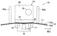
Fig. 8 is the perspective view that part shows Workpiece treating apparatus according to a second embodiment of the present invention;
Fig. 9 is the perspective view that part shows the Workpiece treating apparatus of a third embodiment in accordance with the invention;
Figure 10 is the perspective view that part shows the Workpiece treating apparatus of a fourth embodiment in accordance with the invention.
The specific embodiment
< first embodiment >
In Fig. 1 and Fig. 3, represent the machine direction of Workpiece treating apparatus 10 with MD, and represent to be orthogonal to the crisscross of machine direction MD with CD.
Referring to figs. 1 through Fig. 3, Workpiece treating apparatus 10 comprises: conveyer 12, said conveyer are used for transmitting the workpiece 11 such as fiber mesh material along machine direction MD; With injection unit 14, said injection unit is provided with a plurality of injection orifices 13 (see figure 3)s, and said injection orifices is used for spraying overheated and pressurized vapor jet towards conveyer 12, and said conveyer 12 is positioned at injection orifices 13 belows.Below conveyer 12, be provided with aspirator 15, spray and passed through the steam under pressure jet of conveyer 12 and workpiece 11 by injection unit 14 with suction.Mean at the term " workpiece 11 " of this use and will accept the object handling or process; And in an embodiment of the present invention, said term means the various sheet elements of the known technology of the raw material (for example comprise the netted thing of single or multiple lift thermoplastic fibre and be clipped in the absorbency material between these WEBs) that are widely used as amenities.
Conveyer 12 comprises a pair of endless belt; Said endless belt goes in ring along a direction; That is, the first and second guipure 12a, 12b are suitable for along the workpiece 11 of machine direction MD conveying clamp between said first and second guipures, and for this reason; These guipures 12a, 12b are supported and drive by a plurality of feed roller, so that advance along machine direction MD.More specifically, conveyer 12 is by i.e. first and second feed rollers, 16,17 support and the drivings of at least one pair of feed roller, and said first and second feed rollers are positioned at conveyer 12 belows and lay respectively at both sides along the machine direction MD of injection unit 14.Should be understood that at this in the process of machine direction MD conveying work pieces 11, conveyer 12 can be suitable for along its thickness direction compression workpiece 11 except clamping workpiece 11.
The first and second guipure 12a, 12b can be crooked, and can for example utilize the metal wire rod workpiece processed by stainless steel alloy or signal bronze, such as the plastics part of the braided fiber of polyester fiber or aromatic polyamides, or the metallic plate of perforation form.According to present embodiment; The aperture opening ratio of the first and second guipure 12a, 12b can be in about scope of 10% to 85%, and the gauge or diameter of wire of said first and second guipures can be in the scope of about 0.03mm to 5.0mm and their mesh-density can be in about per inch 2 to the scope of per inch 600.Should be understood that at this aperture opening ratio of first and second guipures, gauge or diameter of wire and mesh-density can be according to suitably being provided with by the skilled worker such as the steam pressure of pressurized vapor jet and workpiece material or structure.The first and second guipure 12a/12b can differ from one another aspect aperture opening ratio and/or the mesh-density.For example, the mesh-density of the first guipure 12a can be higher than the mesh-density of the second guipure 12b.
With reference to Fig. 2; Steam pipework unit 20 is rectangular shape and comprise steam under pressure supply line 19 therein normally; Said steam under pressure supply line extends and is connected with a plurality of laterals 22 along crisscross CD, said lateral along crisscross CD with regular separation.These laterals 22 are connected with steam supply pipe road 19 at the height place of the central axial line that is higher than steam supply pipe road 19 and when extending at the upper reaches when machine direction MD observes, and are crooked then to extending below.The diapire 23 of steam pipework unit 20 is provided with the isolated a plurality of screwed holes 24 of rule along its periphery; And at said outer wall middle section; Have groove 25, said groove is configured as along crisscross CD longer, thereby around one group of openend 22a of lateral 22.Groove 25 is provided with O-ring seals 26, and said O-ring seals is as the leakage barrier that prevents that steam under pressure from leaking.
With reference to Fig. 3, jet tray 21 is that the roof towards the diapire 23 of jet chimney unit 20 of rectangular plate shape member and said jet tray is provided with a plurality of holes 28 along its periphery, and said hole is corresponding with the screwed hole 24 of jet chimney unit 20.Jet chimney unit 20 is fixed to each other through the bolt (not shown) with jet tray 21, and said bolt extends through respective threads hole 24 and corresponding hole 28.Jet tray 21 is entreated the zone to be formed with steam therein and is admitted depressed part 30, and said steam admits depressed part to be connected with the openend 22a of corresponding arm 22, makes steam under pressure can flow into steam from the openend 22a of corresponding arm 22 and admits depressed part 30.
With reference to Fig. 4 to Fig. 6, steam is admitted depressed part 30 to run through its diapire to be formed with a plurality of injection orifices 31, said a plurality of injection orifices along crisscross CD substantially with word shape patterned arrangement.The lower surface 32 of jet tray 21 comprises: central sections 33, and said central sections is corresponding to the above-mentioned middle section of jet tray 21; And the upstream and downstream section, said upstream and downstream section each all each from upstream and downstream edge part 21a, 21b along machine direction MD towards central sections to extending below, and central sections is a level substantially.In other words, lower surface 32 whole protrusions downwards.In said embodiment, the orifice diameter of injection orifices 31 preferably about 0.1mm to the scope of about 0.2mm and injection orifices 31 pitch of arranging preferably at about 0.5mm to the scope of about 10.0mm.Yet, should be understood that at this, can suitably set said factor by the technical staff according to factor such as workpiece material.The cross sectional shape of injection orifices 31 is not limited to ring-type, but can from various polygonal cross-section shapes, select.Under the prerequisite that does not deviate from scope of the present invention, also can make injection orifices 31 go up or the lower part is configured as turbination or pyramid, make the converging property of the steam under pressure jet that can improve injection and the working ability of equipment.
With reference to Fig. 5; On the lower surface 32 of jet tray 21; Border 33a between central sections 33 and the Upstream section is crooked glossily and have no the turning; Make and to limit, and in addition, make the grid of the guipure 12a that wins can not catch the edge part 33a of central sections 33 so that stop transmission because of the friction between the lower surface 32 and the first guipure 12a causes the wearing and tearing of not expecting to both.
With reference to Fig. 7, when the lower surface 32 of jet tray 21 when the first guipure 12a slides, the jet tray 21 of injection unit 14 sprays the steam under pressure jets towards workpiece 11.Particularly; When first feed roller 16 and second feed roller 17 of the upstream and downstream that when machine direction MD sees, lays respectively at injection unit 14 is located such that these feed rollers 16,17 can slightly upwards promote given section of conveyer belt 12, and therefore be limited to first and second feed rollers 16, between 17 and the region R below the adjacent lower surface 32 of jet tray 21 compare by tension more consumingly with all the other sections.The lower surface 32 of jet tray 21 contacts with region R slidably, so that make region R slightly or downwarping lightly, and therefore, the first guipure 12a partly is out of shape and is crooked.Though lower surface 32 applies pressure to whole region R (promptly usually; The reclinate corresponding region as graphic of the first guipure 12a, workpiece 11 and the second guipure 12b); But can use the guipure like second guipure 12b harder, so that make the first guipure 12a among the first and second guipure 12a, the 12b only be out of shape with case of bending than the first guipure 12a.Although there is not diagram, the lower surface 32 of jet tray 21 can be positioned to be lower than the corresponding central axial line 16a of first and second feed rollers 16,17, the height place of 17a, so that force lower surface 32 more closely and slidably to contact with the first guipure 12a.
When from the injection orifices 31 of lower surface 32 split sheds of jet tray 21 when workpiece 11 sprays the steam under pressure jets, the openend of corresponding injection orifices 31 and the distance between the workpiece 11 are zero basically.As a result, the steam under pressure jet can be ejected into workpiece 11 and have no leakage from injection orifices 31, that is, and and with the ejection efficiency of optimum.Handling in the process of workpiece 11 continuously, conveyer belt 12 may cause air-flow more or less along advancing of machine direction MD, and such air-flow can be easy to make that near injection orifices 31 temperature of lower surface 32 reduce.Especially when workpiece 11 and injection orifices 31 remarkable when spaced apart, the steam under pressure jet can cool off, and accumulates in workpiece 11 lip-deep water droplets with formation.Yet according to present embodiment, the steam under pressure jet can be directly injected to finished product 11 and not contact with surrounding air, and the steam under pressure jet can not cool off to form and accumulates in workpiece 11 lip-deep water droplets.In addition; Workpiece treating apparatus 10 according to present embodiment is suitable for via the first guipure 12a steam under pressure jet being ejected into workpiece 11, makes the steam under pressure jet to spray workpiece 11 down in controlled condition (such as injection orifices 31 and workpiece 11 distance, the temperature of steam under pressure jet and the quantity of the steam jet that time per unit sprays apart).Folder is not established the first guipure 12a if injection orifices 31 maintenances contact with workpiece 11 slidably, and then when near the temperature the injection orifices 31 of jet tray 21 were higher than the fusion point of workpiece 11, the fiber that constitutes workpiece 11 maybe partly mutual adhere.In addition, when workpiece 11 in uneven thickness, jet tray 21 parts can not keep slidably contacting with workpiece 11, and can not make the jetting stability of steam under pressure jet to workpiece 11.In addition, in said situation, possibly be disordered structure with surface fiber in the zone that jet tray 21 slidably contacts, thereby cause the workpiece quality deterioration.
As stated; The lower surface 32 of jet tray 21 not only keeps contacting slidably with the first guipure 12a; Be limited to first and second feed rollers 16, between 17 and bear in the region R that is higher than all the other regional tension force, the lower surface 32 of jet tray 21 keeps slidably contacting with the first guipure 12a by this way: make lower surface 32 force first guipure 12a slight bending downwards during spraying steam under pressure.Therefore, even the first guipure 12a is formed by the polyester fiber WEB etc. of braiding and its surface has irregular portion, workpiece 11 also can pressurized steam evenly and injection reliably.For the bending distortion of at least the first guipure 12a that makes conveyer belt 12 to expect; The first guipure 12a has the hardness of the lower surface 32 that is lower than jet tray 21; More specifically; The lower surface 32 of jet tray 21 preferably has between about 300 hardness Hv to about 1200 scopes, and the first guipure 12a preferably has the hardness that is lower than this level.
< second embodiment >
Fig. 8 shows Workpiece treating apparatus 10 according to a second embodiment of the present invention.In essential structure, according to the Workpiece treating apparatus of second embodiment 10 substantially with according to the equipment class of first embodiment seemingly, and therefore, description will only limit to the characteristic that is different from first embodiment of second embodiment.
With reference to Fig. 8, be provided with a pair of dividing plate 40a, 40b in the both sides of injection unit 14 at a distance of certain distance along machine direction MD and conveyer belt 12.Dividing plate 40a, 40b are advantageously used in and prevent that air from flowing in the region R; So that near the temperature in preventing the injection orifices 31 of lower surface 32 descends; To prevent temperature decline by the steam under pressure jet of injection orifices 31 injections; And therefore, permission will keep the steam under pressure jet of preferred temperature to be ejected into workpiece 11.Although any one among these dividing plates 40a, the 40b all can be positioned at the upper reaches or downstream, to realize desired effects, dividing plate 40a preferably is positioned at the upper reaches, and reason is that air is easy to flow in the region R along the direction of conveying work pieces 11.
< the 3rd embodiment >
Fig. 9 shows the Workpiece treating apparatus 10 of a third embodiment in accordance with the invention.In essential structure, substantially with similar according to the workpiece of first embodiment, therefore, description will only limit to the characteristic that is different from first embodiment of the 3rd embodiment according to the Workpiece treating apparatus of the 3rd embodiment 10.
With reference to Fig. 9, according to present embodiment, the respective lower of dividing plate 40a, 40b contacts with the first guipure 12a of conveyer belt 12.According to present embodiment, can prevent that air from getting into region R along machine direction MD when conveyer belt 12 is advanced.With this kind mode, can limit that near the injection orifices 31 of lower surface 32 temperature descend and the temperature that can limit the steam under pressure jet that is sprayed by injection orifices 31 more reliably descends.
< the 4th embodiment >
Figure 10 shows the Workpiece treating apparatus 10 of a fourth embodiment in accordance with the invention.In essential structure, basic according to the Workpiece treating apparatus 10 of the 4th embodiment with similar according to the workpiece of first embodiment, therefore, the characteristic that is different from first embodiment that only limits to the 4th embodiment is described.
With reference to Figure 10, according to present embodiment, Workpiece treating apparatus 10 is provided with heating cabinet 50, and said heating cabinet is sealed the region R of whole injection unit 14 and conveyer belt 12.Heating cabinet 50 is suitable for its inside being remained on predetermined temperature and said heating cabinet is formed with a pair of slit 52 through heater 51, and said a pair of slit allows conveyer belt 12 through wherein.The region R of whole injection unit 14 and conveyer belt 12 is basic and surrounding air is isolated and inside heating cabinet 50 remains on predetermined temperature.With this kind mode, can the steam under pressure jet that predetermined temperature remains on predeterminated level and predetermined temperature can be ejected into workpiece 11 and the temperature of the steam under pressure jet that before steam jet is ejected into workpiece 11, sprayed by injection orifices 31 does not simultaneously descend.
As stated, Workpiece treating apparatus 10 according to the present invention is not limited to any concrete processing, but can be applied in various process field, such as, have the fibers melt combination of relatively low melt temperature, the texture processing of non-woven fabric plate and the cleaning of textile oil.
Employed in this article term " first " and " second " only are used for similar components is distinguished.
The many aspects of the invention described above can be arranged with one or more clauses and subclauses below at least:
(i) a kind of Workpiece treating apparatus, said Workpiece treating apparatus have machine direction, are orthogonal to the crisscross of machine direction, and said equipment comprises: conveyer belt, said conveyer belt are used for along the machine direction conveying work pieces; And injection unit, said injection unit is used for overheated and pressurized vapor jet are ejected into workpiece, wherein:
Injection unit has lower surface, and said lower surface is provided with a plurality of injection orifices along crisscross layout;
Conveyer belt has flexible and comprises in the face of first guipure of the upper surface of workpiece with in the face of second guipure of the lower surface of workpiece; Wherein, First and second guipures cooperatively interact, so as with workpiece clamp between said first and second guipures and along the machine direction conveying work pieces; And
Lower surface contacts with first guipure slidably, so that at least the first guipure in downwarping first and second guipures.
In above clauses and subclauses (i), describe of the present invention aspect one or more in the following advantageous effects can be provided:
When the lower surface of injection unit just forces the first guipure downwarping with lower surface when first guipure slidably contacts, between injection orifices and workpiece, do not exist the temperature of distance and steam under pressure jet can not descend basically.With this kind mode, guarantee the high efficiency of spraying.The lower surface of injection unit not only keeps slidably contacting with first guipure; Also force first guipure to protrude distortion downwards; And therefore guarantee that even guipure has irregular portion in its surface, also can utilize the steam under pressure jet that keeps steady temperature to handle surface of the work.
In addition, according to others one or more in following examples are provided:
(ii) through the lower surface of injection unit, first and second guipures all can downwarping.
(iii) second guipure can first guipure can be through the lower surface downwarping of injection unit firmly and only than first guipure.
(iv) one can be positioned at the below, zone towards injection unit of conveyer belt for a pair of feed roller of set a distance along the machine direction space; Make conveyer belt slightly upwards mentioned by a pair of feed roller; And therefore, all the other the regional tension force that born towards said injection unit that are higher than said conveyer belt are born in the zone of second guipure, wherein; In this zone, the lower surface of injection unit contacts with first guipure slidably.
Said conveyer belt towards all the other zones of said injection unit along machine direction preferably between feed roller.
(v) injection orifices preferably be arranged on injection unit lower surface be arranged to contact first guipure the section in.
(vi) the lower surface integral body of injection unit preferably downwards protrusion and the lower surface of injection unit by under the position contact first guipure.
(vii) the lower surface of injection unit preferably includes central sections; And Upstream section, said Upstream section extends downwardly into central sections from the upstream edge portion of injection unit along machine direction, and central sections is level, and wherein, central sections and upper reaches section boundary are crooked and have no the turning.
(viii) by under section preferably be positioned at the central sections in the middle of Upstream section and the tract, tract along said machine direction from said by under the downstream edge portion that section extends up to said injection unit.
Preferably, said central sections and said downstream section boundary are crooked and have no the turning.
(vix) preferably, injection orifices be arranged on by under section in.
(x) preferably, the section of contact first guipure of the lower surface of injection unit is positioned at and is lower than the height place that feed roller contacts the height of second guipure.
The lower surface of injection unit can be positioned at the height place of the corresponding central axial line that is lower than first and second feed rollers.
(xi) upper surface of first guipure preferably is higher than the section of the lower surface of injection unit, and at the upstream side at least of section that is arranged to contact first guipure of the lower surface of injection unit, the section of said lower surface is arranged to contact first guipure.
The upper surface of first guipure preferably is higher than the section that is arranged to contact with the downstream at upstream side first guipure of the lower surface of injection unit.
(xii) preferably,, be provided with dividing plate, get into this zone to stop air from the upper reaches along the only upstream side of machine direction at injection unit.
(xiii) along said machine direction on the upstream side of said injection unit and in the downstream each, dividing plate can be set get into said zone to stop air.
(xiv) each dividing plate all can contact conveyer slidably.
Preferably, each dividing plate all contacts with the upper surface of first guipure slidably.
(xv) heating cabinet can be arranged to seal the zone corresponding to injection unit of injection unit and conveyer belt.
According to above (ii) with (xv) in embodiment, guarantee well that in (a) the form that one or more advantageous effects of statement, the characteristic of said embodiment can appear separately perhaps with any combination appears.Other advantageous effects of corresponding embodiment can be as obtaining discussing in the corresponding associated description.
Claims (15)
1. Workpiece treating apparatus, said equipment has machine direction, is orthogonal to the crisscross of said machine direction, and said equipment comprises: conveyer belt, said conveyer belt are used for along said machine direction conveying work pieces; And injection unit, said injection unit is used for overheated and pressurized vapor jet are ejected into said workpiece, wherein:
Said injection unit has lower surface, and said lower surface is along said crisscross a plurality of injection orifices that are provided with;
Said conveyer belt has flexible and comprises in the face of first guipure of the upper surface of said workpiece with in the face of second guipure of the lower surface of said workpiece; Wherein, Said first guipure and said second guipure cooperatively interact, so that said workpiece clamp is transmitted said workpiece in the middle of said first guipure and said second guipure and along said machine direction; And
The said lower surface of said injection unit can contact with said first guipure slidably, so that make the said at least first guipure downwarping in said first guipure and said second guipure.
2. Workpiece treating apparatus according to claim 1, wherein, said first guipure and said second guipure are all by the said lower surface downwarping of said injection unit.
3. Workpiece treating apparatus according to claim 1, wherein, said second guipure than said first guipure hard and only said first guipure by the said lower surface downwarping of said injection unit.
4. according to any described workpiece device in the claim 1 to 3; Wherein, Be spaced from each other along said machine direction and one be positioned at the below, zone towards said injection unit of said conveyer belt for a pair of feed roller of set a distance, make said conveyer belt mentioned slightly, therefore by said a pair of feed roller; Other the regional tension force that is born towards said injection unit that is higher than said conveyer belt is born in the said zone of said second guipure; Wherein, in said zone, the said lower surface of said injection unit can contact with said first guipure slidably.
5. according to any described Workpiece treating apparatus in the claim 1 to 4, wherein, said injection orifices be arranged on said injection unit lower surface be arranged to contacted section of said first guipure in.
6. according to any described Workpiece treating apparatus in the right 1 to 5, wherein, the whole protrusion downwards of the said lower surface of said injection unit and said lower surface by under the position contact said first guipure.
7. according to any described Workpiece treating apparatus in the claim 1 to 6, wherein, the said lower surface of said injection unit comprises: by under section; And Upstream section; The upstream edge portion of said Upstream section along said machine direction from said injection unit extend downwardly into said by under section; And said by under section be level, wherein, said central sections and said upper reaches section boundary are crooked and have no the turning.
8. Workpiece treating apparatus according to claim 7; Wherein, Said by under section be the central sections between said Upstream section and tract, the downstream edge portion that section extend up to said injection unit of said tract under along said machine direction from said leaning on most.
9. according to claim 7 or 8 described Workpiece treating apparatus, wherein, said injection orifices be arranged on said by under section in.
10. according to any described Workpiece treating apparatus in the claim 6 to 9, wherein, the section of said first guipure of the contact of the said lower surface of said injection unit is positioned at and is lower than the height place that said feed roller contacts the height of said second guipure.
11. according to any described Workpiece treating apparatus in the claim 1 to 10; Wherein, The upper surface of said first guipure is higher than the section of the lower surface of said injection unit; The said lower surface of said injection unit be arranged to contact on the upstream side at least of section of said first guipure, the section of the lower surface of said injection unit is arranged to contact said first guipure.
12. according to any described Workpiece treating apparatus in the claim 1 to 11, wherein, said injection unit on the only upstream portion of said machine direction, be provided with dividing plate, flow into the said zone from the upper reaches to block air.
13. according to any said Workpiece treating apparatus in the claim 1 to 12, wherein, said injection unit on the upstream side of said machine direction and in the downstream each, be provided with dividing plate, go in said zone with obstruct airflow.
14. according to claim 12 or 13 described Workpiece treating apparatus, wherein, each said dividing plate all can with said conveyer sliding-contact.
15. according to any described Workpiece treating apparatus in the claim 1 to 14, wherein, be provided with heating cabinet, to seal the zone corresponding to said injection unit of said injection unit and said conveyer belt.
Applications Claiming Priority (3)
| Application Number | Priority Date | Filing Date | Title |
|---|---|---|---|
| JP2010-059939 | 2010-03-16 | ||
| JP2010059939A JP5520096B2 (en) | 2010-03-16 | 2010-03-16 | Work processing device |
| PCT/JP2011/001562 WO2011114730A1 (en) | 2010-03-16 | 2011-03-16 | Work treating apparatus |
Publications (1)
| Publication Number | Publication Date |
|---|---|
| CN102803595A true CN102803595A (en) | 2012-11-28 |
Family
ID=44648842
Family Applications (1)
| Application Number | Title | Priority Date | Filing Date |
|---|---|---|---|
| CN2011800138590A Pending CN102803595A (en) | 2010-03-16 | 2011-03-16 | Work treating apparatus |
Country Status (5)
| Country | Link |
|---|---|
| US (1) | US20120325619A1 (en) |
| EP (1) | EP2547818A4 (en) |
| JP (1) | JP5520096B2 (en) |
| CN (1) | CN102803595A (en) |
| WO (1) | WO2011114730A1 (en) |
Cited By (1)
| Publication number | Priority date | Publication date | Assignee | Title |
|---|---|---|---|---|
| CN107640641A (en) * | 2017-11-01 | 2018-01-30 | 湖州市练市新民纺织有限公司 | A kind of doubling frame for protecting raw material line |
Families Citing this family (1)
| Publication number | Priority date | Publication date | Assignee | Title |
|---|---|---|---|---|
| MX2018002563A (en) * | 2018-02-28 | 2019-09-02 | Clevot S A De C V | Head-type device for the dry cleaning and sanitization of flat sanitary conveyor belts. |
Citations (6)
| Publication number | Priority date | Publication date | Assignee | Title |
|---|---|---|---|---|
| US3033721A (en) * | 1955-04-12 | 1962-05-08 | Chicopee Mfg Corp | Method and machine for producing nonwoven fabric and resulting product |
| JPS54123293A (en) * | 1978-03-16 | 1979-09-25 | Mitsubishi Rayon Co | Preparation of sheettlike matter on which pulverulent body is laminated and its device |
| JPH0734313A (en) * | 1993-07-16 | 1995-02-03 | Asahi Chem Ind Co Ltd | Device for producing sheetlike nonwoven fabric |
| CN1107279A (en) * | 1993-04-19 | 1995-08-23 | 古尔公司 | Plane composite material comprising a pierced film and thermoplastic fibers, its use and method of manufacture |
| JP2005076162A (en) * | 2003-09-03 | 2005-03-24 | Mitsubishi Rayon Eng Co Ltd | Steam treatment method for fiber fabric |
| CN1688758A (en) * | 2002-10-08 | 2005-10-26 | 三菱丽阳工程株式会社 | Pressurized steam-jetting nozzle, and method and apparatus for producing nonwoven fabric using the nozzle |
Family Cites Families (6)
| Publication number | Priority date | Publication date | Assignee | Title |
|---|---|---|---|---|
| US4297404A (en) * | 1977-06-13 | 1981-10-27 | Johnson & Johnson | Non-woven fabric comprising buds and bundles connected by highly entangled fibrous areas and methods of manufacturing the same |
| IT1233086B (en) * | 1989-05-31 | 1992-03-14 | Claudio Governale | Consolidating loose fibrous nonwoven structures into web |
| JP3437873B2 (en) * | 1994-05-13 | 2003-08-18 | 三菱レイヨン・エンジニアリング株式会社 | Entangling method by injection of high pressure fluid |
| FR2734285B1 (en) * | 1995-05-17 | 1997-06-13 | Icbt Perfojet Sa | PROCESS FOR THE MANUFACTURE OF A NON-WOVEN TEXTILE TABLECLOTH BY PRESSURIZED WATER JETS, AND INSTALLATION FOR CARRYING OUT SAID METHOD |
| GB0013302D0 (en) * | 2000-06-02 | 2000-07-26 | B & H Res Ltd | Formation of sheet material using hydroentanglement |
| JP4439854B2 (en) * | 2002-10-08 | 2010-03-24 | 三菱レイヨン・エンジニアリング株式会社 | Non-woven fabric manufacturing method using pressurized steam jet nozzle |
-
2010
- 2010-03-16 JP JP2010059939A patent/JP5520096B2/en not_active Expired - Fee Related
-
2011
- 2011-03-16 CN CN2011800138590A patent/CN102803595A/en active Pending
- 2011-03-16 WO PCT/JP2011/001562 patent/WO2011114730A1/en active Application Filing
- 2011-03-16 US US13/581,164 patent/US20120325619A1/en not_active Abandoned
- 2011-03-16 EP EP11755921.1A patent/EP2547818A4/en not_active Withdrawn
Patent Citations (6)
| Publication number | Priority date | Publication date | Assignee | Title |
|---|---|---|---|---|
| US3033721A (en) * | 1955-04-12 | 1962-05-08 | Chicopee Mfg Corp | Method and machine for producing nonwoven fabric and resulting product |
| JPS54123293A (en) * | 1978-03-16 | 1979-09-25 | Mitsubishi Rayon Co | Preparation of sheettlike matter on which pulverulent body is laminated and its device |
| CN1107279A (en) * | 1993-04-19 | 1995-08-23 | 古尔公司 | Plane composite material comprising a pierced film and thermoplastic fibers, its use and method of manufacture |
| JPH0734313A (en) * | 1993-07-16 | 1995-02-03 | Asahi Chem Ind Co Ltd | Device for producing sheetlike nonwoven fabric |
| CN1688758A (en) * | 2002-10-08 | 2005-10-26 | 三菱丽阳工程株式会社 | Pressurized steam-jetting nozzle, and method and apparatus for producing nonwoven fabric using the nozzle |
| JP2005076162A (en) * | 2003-09-03 | 2005-03-24 | Mitsubishi Rayon Eng Co Ltd | Steam treatment method for fiber fabric |
Cited By (2)
| Publication number | Priority date | Publication date | Assignee | Title |
|---|---|---|---|---|
| CN107640641A (en) * | 2017-11-01 | 2018-01-30 | 湖州市练市新民纺织有限公司 | A kind of doubling frame for protecting raw material line |
| CN107640641B (en) * | 2017-11-01 | 2023-06-30 | 湖州市练市新民纺织有限公司 | Doubling machine for protecting raw material line |
Also Published As
| Publication number | Publication date |
|---|---|
| EP2547818A1 (en) | 2013-01-23 |
| JP5520096B2 (en) | 2014-06-11 |
| US20120325619A1 (en) | 2012-12-27 |
| WO2011114730A1 (en) | 2011-09-22 |
| JP2011190562A (en) | 2011-09-29 |
| EP2547818A4 (en) | 2014-04-02 |
Similar Documents
| Publication | Publication Date | Title |
|---|---|---|
| EP0147904B1 (en) | Method for production of non-woven fabric | |
| TWI529275B (en) | Industrial fabric for production of nonwovens, and method of making thereof | |
| CA2736765C (en) | Permeable belt for nonwovens production | |
| CA2604481C (en) | Industrial fabrics having thermally sprayed protective coating | |
| CN108138405B (en) | Method for producing nonwoven fabric with uneven pattern | |
| US20160107199A1 (en) | Washing system for cleaning a moving web | |
| CN1608837A (en) | Fiber laminates and methods for producing them | |
| KR20060121727A (en) | Process and apparatus for manufacturing spun-bonded fabric | |
| JPS5825780B2 (en) | Manufacturing method of fiber strand pine | |
| US20230383447A1 (en) | Methods of creating soft and lofty nonwoven webs | |
| CN102803595A (en) | Work treating apparatus | |
| CN100500969C (en) | Pressurized steam-jetting nozzle, and method and apparatus for producing nonwoven fabric using the nozzle | |
| US20070137937A1 (en) | Conveyor lubricating apparatus | |
| KR930013310A (en) | Continuous manufacturing apparatus and method of mineral wool nonwoven fabric | |
| CN104185703B (en) | The method of the conveyer belt of paper web is manufactured for Clean- | |
| KR102600842B1 (en) | industrial fabrics | |
| IL146866A (en) | Device for treating sheet materials using pressurised water jets | |
| JP7461739B2 (en) | Manufacturing method and manufacturing device for composite nonwoven fabric | |
| JPWO2009069403A1 (en) | Industrial fabrics for papermaking and pressing | |
| JP7088747B2 (en) | Non-woven fabric manufacturing equipment | |
| WO2024008383A1 (en) | Method for transporting a cellulose blank structure via a buffering module and buffering module | |
| KR101674901B1 (en) | Contactless film material traverse direction guiding device | |
| JP5591648B2 (en) | High pressure steam jet nozzle for processing fiber sheet and processing method of fiber sheet using the same nozzle | |
| EP3344810A1 (en) | Embossing device | |
| TH41505A3 (en) | A process and equipment for the formation of fluff on a sheet-like textile sheet material by blow-hitting with a high-pressure fluid. |
Legal Events
| Date | Code | Title | Description |
|---|---|---|---|
| C06 | Publication | ||
| PB01 | Publication | ||
| C10 | Entry into substantive examination | ||
| SE01 | Entry into force of request for substantive examination | ||
| C02 | Deemed withdrawal of patent application after publication (patent law 2001) | ||
| WD01 | Invention patent application deemed withdrawn after publication |
Application publication date: 20121128 |