CN103299511A - Method for integrating controls for captive power generation facilities with controls for metallurgical facilities - Google Patents
Method for integrating controls for captive power generation facilities with controls for metallurgical facilities Download PDFInfo
- Publication number
- CN103299511A CN103299511A CN2011800633742A CN201180063374A CN103299511A CN 103299511 A CN103299511 A CN 103299511A CN 2011800633742 A CN2011800633742 A CN 2011800633742A CN 201180063374 A CN201180063374 A CN 201180063374A CN 103299511 A CN103299511 A CN 103299511A
- Authority
- CN
- China
- Prior art keywords
- generator
- load
- control parameter
- power
- controller
- Prior art date
- Legal status (The legal status is an assumption and is not a legal conclusion. Google has not performed a legal analysis and makes no representation as to the accuracy of the status listed.)
- Granted
Links
Images


Classifications
-
- H—ELECTRICITY
- H02—GENERATION; CONVERSION OR DISTRIBUTION OF ELECTRIC POWER
- H02J—CIRCUIT ARRANGEMENTS OR SYSTEMS FOR SUPPLYING OR DISTRIBUTING ELECTRIC POWER; SYSTEMS FOR STORING ELECTRIC ENERGY
- H02J3/00—Circuit arrangements for ac mains or ac distribution networks
- H02J3/04—Circuit arrangements for ac mains or ac distribution networks for connecting networks of the same frequency but supplied from different sources
- H02J3/06—Controlling transfer of power between connected networks; Controlling sharing of load between connected networks
-
- H—ELECTRICITY
- H02—GENERATION; CONVERSION OR DISTRIBUTION OF ELECTRIC POWER
- H02J—CIRCUIT ARRANGEMENTS OR SYSTEMS FOR SUPPLYING OR DISTRIBUTING ELECTRIC POWER; SYSTEMS FOR STORING ELECTRIC ENERGY
- H02J3/00—Circuit arrangements for ac mains or ac distribution networks
- H02J3/12—Circuit arrangements for ac mains or ac distribution networks for adjusting voltage in ac networks by changing a characteristic of the network load
- H02J3/14—Circuit arrangements for ac mains or ac distribution networks for adjusting voltage in ac networks by changing a characteristic of the network load by switching loads on to, or off from, network, e.g. progressively balanced loading
-
- H—ELECTRICITY
- H02—GENERATION; CONVERSION OR DISTRIBUTION OF ELECTRIC POWER
- H02J—CIRCUIT ARRANGEMENTS OR SYSTEMS FOR SUPPLYING OR DISTRIBUTING ELECTRIC POWER; SYSTEMS FOR STORING ELECTRIC ENERGY
- H02J2310/00—The network for supplying or distributing electric power characterised by its spatial reach or by the load
- H02J2310/10—The network having a local or delimited stationary reach
- H02J2310/12—The local stationary network supplying a household or a building
-
- Y—GENERAL TAGGING OF NEW TECHNOLOGICAL DEVELOPMENTS; GENERAL TAGGING OF CROSS-SECTIONAL TECHNOLOGIES SPANNING OVER SEVERAL SECTIONS OF THE IPC; TECHNICAL SUBJECTS COVERED BY FORMER USPC CROSS-REFERENCE ART COLLECTIONS [XRACs] AND DIGESTS
- Y02—TECHNOLOGIES OR APPLICATIONS FOR MITIGATION OR ADAPTATION AGAINST CLIMATE CHANGE
- Y02B—CLIMATE CHANGE MITIGATION TECHNOLOGIES RELATED TO BUILDINGS, e.g. HOUSING, HOUSE APPLIANCES OR RELATED END-USER APPLICATIONS
- Y02B70/00—Technologies for an efficient end-user side electric power management and consumption
- Y02B70/30—Systems integrating technologies related to power network operation and communication or information technologies for improving the carbon footprint of the management of residential or tertiary loads, i.e. smart grids as climate change mitigation technology in the buildings sector, including also the last stages of power distribution and the control, monitoring or operating management systems at local level
- Y02B70/3225—Demand response systems, e.g. load shedding, peak shaving
-
- Y—GENERAL TAGGING OF NEW TECHNOLOGICAL DEVELOPMENTS; GENERAL TAGGING OF CROSS-SECTIONAL TECHNOLOGIES SPANNING OVER SEVERAL SECTIONS OF THE IPC; TECHNICAL SUBJECTS COVERED BY FORMER USPC CROSS-REFERENCE ART COLLECTIONS [XRACs] AND DIGESTS
- Y04—INFORMATION OR COMMUNICATION TECHNOLOGIES HAVING AN IMPACT ON OTHER TECHNOLOGY AREAS
- Y04S—SYSTEMS INTEGRATING TECHNOLOGIES RELATED TO POWER NETWORK OPERATION, COMMUNICATION OR INFORMATION TECHNOLOGIES FOR IMPROVING THE ELECTRICAL POWER GENERATION, TRANSMISSION, DISTRIBUTION, MANAGEMENT OR USAGE, i.e. SMART GRIDS
- Y04S20/00—Management or operation of end-user stationary applications or the last stages of power distribution; Controlling, monitoring or operating thereof
- Y04S20/20—End-user application control systems
- Y04S20/222—Demand response systems, e.g. load shedding, peak shaving
Abstract
A control system for a combined power generation and metallurgical plant facility integrates generator-side and load-side control to provide coordinated operation of the two processes. The power generation facility includes one or more generator units and the metallurgical plant facility includes one or more controllable loads. Operating characteristics of the one or more loads are fed back to the one or more generator units through a master controller to determine input control parameters for the one or more generator units. Similarly control signals and operating characteristics of the one or more generators are fed forward to the one or more loads through the master controller to determine input control parameters for the one or more loads. Using feed-forward as well as feed-back loops to exchange generator output and load set-point information, power balance between the generator units and controlled loads is maintained within an operating envelope.
Description
Technical field
Described embodiment relates in general to for controlled electric loading and the integrated control system of generator, relates more specifically to be used to the integrated control system of providing generating (captive power generation) and smelting facility for oneself.
Background technology
Practical electric device moves based on the control scheme that is designed to regulate the output of generator unit power usually, satisfying the power demand set point of selecting for one or more loads, thereby keeps the overall power balance in this electric system.In order to provide generator power to regulate, developed some control strategies, they get up the automatic administrative connection of the boiler of a unit and turbogenerator with according to the coordination mode operation, and in response to the change in long term of power demand.Become in power industry these control strategies of relative standard are usually included in the turbine level and carry out a kind of FREQUENCY CONTROL.The deviation of the rotational frequency by monitoring this turbogenerator, the respective change of the mechanical energy that provides by this boiler has been mated the variation of electrical power requirements in the reaction mode.Thereby, kept the overall power balance in this system.
Be used for the short-term trend of reply power demand or the responding system of other unexpected electric loading transitions and also be developed out, and be integrated in some practical electric devices.Because the minimizing of loading demand, carry or transition such as disconnection can require immediately turbine response such as throwing.High pressure and low pressure bypass system can be used to by will being sent to condenser (walking around this turbine) from the superfluous steam of the boiler of this generator unit reducing electricity output, respond if having time and the machinery that reduces it exports to mate the steam demand of the minimizing of this turbine up to this boiler (with its common high thermal inertia).If high pressure or low pressure bypass system are not installed, then alternately use mechanical and electrical safety valve (ERV), in response to accumulation of pressure superfluous steam is discharged into the atmosphere, be supplied to the steam of this turbine to satisfy the demands thereby reduce.Yet, can reduce general arrangement efficient because of energy loss to the atmosphere released vapour.For the transition that increases power demand, connect such as load, can use similar bypass system that additional steam is sent to this turbine, suppose to have included in this bypass system and enabled at present the used vapour source, remedy the demand that its steam is exported to be increased to satisfy if having time up to this boiler.
Summary of the invention
A broad aspect, some embodiments provide the control system of the operation that is used for the coordination electric power system, and described electric power system comprises at least one generator and at least one controllable load.Described control system comprises: engine controller, and related with each generator in described at least one generator, and control described at least one generator in response to control parameter generator and export to realize overall generator; Load controller, related with each load in described at least one load, and control parameter in response to load and control described at least one load to realize the overall load set point; And main system controller, be communicatively linked to described engine controller and described load controller, and be configured to produce described load control parameter to realize described overall load set point by the operation characteristic based on described at least one generator, and produce described control parameter generator to realize described overall generator output by the operation characteristic based on described at least one load, coordinate the operation of described at least one generator and described at least one load.
In another broad aspect, some embodiments provide electric power system, and described electric power system comprises: at least one generator, export to operate in overall generator in response to control parameter generator; At least one load is controlled parameter to operate in the overall load set point in response to load; And main system controller, be attached to and be configured to produce described load control parameter to realize described overall load set point by the operation characteristic based on described at least one generator, and produce described control parameter generator to realize described overall generator output by the operation characteristic based on described at least one load, coordinate the operation of described at least one generator and described at least one load.
In another broad aspect, some embodiments provide the method for the operation that is used for the coordination electric power system, and described electric power system comprises at least one generator and at least one controllable load.Described method comprises: the operation characteristic of described at least one generator of monitoring; The operation characteristic of described at least one load of monitoring; And by producing load control parameter based on the operation characteristic of described at least one generator to realize described overall load set point, and by producing control parameter generator based on the operation characteristic of described at least one load to realize described overall generator output, coordinate the operation of described at least one generator and described at least one load.
In another broad aspect, some embodiments provide the controller of the operation that is used for coordinating electric power system, and described electric power system comprises at least one generator and by at least one controllable load of described at least one generator powered.Described controller comprises: generator interface, be used for receiving the signal of the operation characteristic that characterizes described at least one generator, and be used for providing control parameter generator to the engine controller related with described at least one generator, described engine controller is exported with the overall generator of realizing described at least one generator in response to described control parameter generator; Loading interfaces, be used for receiving the signal of the operation characteristic that represents described at least one load, and be used for providing load control parameter to the load controller related with described at least one load, described load controller is controlled parameter to realize the overall load set point of described at least one load in response to described load; And processor, be configured to by determining that based on the operation characteristic of described at least one generator described load control parameter is to realize described overall load set point, and by determining that based on the operation characteristic of described at least one load described control parameter generator to realize overall generator output, provides the integrated control to described at least one generator and described at least one load.
In another broad aspect, some embodiments provide electric device, described electric device comprises: at least one generator, be configured to at least one controllable load power supply, described at least one generator responds is exported to operate in overall generator in control parameter generator, and described at least one load response is controlled parameter to operate in the overall load set point in load; And main system controller, be attached to and be configured to produce described load control parameter to realize described overall load set point by the operation characteristic based on described at least one generator, and produce described control parameter generator to realize the output of overall generator by the operation characteristic based on described at least one load, coordinate the operation of described at least one generator and described at least one load.
These and other aspect is set forth in this article.
Description of drawings
This paper provides to the embodiment detailed description of (comprising preferred embodiment), in the accompanying drawings below with reference to the following drawings:
Fig. 1 shows a system with power control of integrated generating pusher side and load-side with the circuit diagram of simplifying;
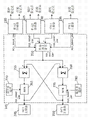
Fig. 2 shows the system of another power control with integrated generating pusher side and load-side with the circuit diagram of simplifying;
Fig. 3 has illustrated the general survey that is used for the control system of system shown in Figure 3 with schematic diagram;
Fig. 4 illustrates in greater detail arc furnace controller shown in Figure 3 with schematic diagram;
Fig. 5 illustrates in greater detail ladle furnace shown in Figure 3 (ladle furnace) controller with schematic diagram;
Fig. 6 A illustrates in greater detail unit telegon shown in Figure 3 with schematic diagram;
Fig. 6 B with schematic diagram illustrate in greater detail shown in Fig. 6 A stop increase (block increase) control and stop reduce (block descrease) control;
Fig. 6 C illustrates in greater detail the revolution control module shown in Fig. 6 A (runback control module) with schematic diagram;
Fig. 7 illustrates in greater detail CTG master controller shown in Figure 3 with schematic diagram;
Fig. 8 A illustrates in greater detail the part of main system controller shown in Figure 3 with schematic diagram;
Fig. 8 B illustrates in greater detail another part of main system controller shown in Figure 3 with schematic diagram;
Fig. 8 C illustrates in greater detail another part of main system controller shown in Figure 3 with schematic diagram;
Fig. 8 D illustrates in greater detail another part of main system controller shown in Figure 3 with schematic diagram;
Fig. 8 E illustrates in greater detail another part of main system controller shown in Figure 3 with schematic diagram;
Fig. 8 F illustrates in greater detail another part of main system controller shown in Figure 3 with schematic diagram;
Fig. 9 shows the method for using control system shown in Figure 3 to carry out electrode skid (slip) or change with flow chart.
Should be understood that these figure only are exemplary.All of these figure with reference to all only for the illustration purpose, and are not intended to limit by any way the scope of embodiment described below.For convenience, also can be in repeat reference numerals (being with or without offspring) among whole figure with parts like the representation class or feature.
Embodiment
Large-scale smelting device and facility such as what use, can represent the significant and challenging load for power generating equipment in melting and the processing of other metallic ores.Some examples of these facilities comprise arc furnace (EAF) and ladle furnace (LMF).The power draw of arc furnace (power draw) normally big, idle (reactive) (but also can comprise meritorious (real) component), and be alterable height.If this smelting device is connected to electrical network big and robust, what at the big power fluctuation in this arc furnace place of run duration, also only represents from the generator of supplying this electrical network and it seems little overall disturbance.As a result, though in load-side without any electric adjustment, the generator of coordination control also can be enough to stablize the equipment fault of this electrical network, limit frequency drift and averting a calamity property.
Yet, bearing power is stable still be implemented to keep good power-balance and efficiently smelting device move.Be used for the control scheme of arc furnace (direct current and three-phase) in for example U.S. Patent No. 6,603,795, U.S. Patent No. 7,212,561, U.S. Patent No. 7,212,562 and U.S. Patent No. 7, describe in 257,146, the full content of each patent in these patents is included in hereby by reference.These control schemes have utilized one or more different technologies that power consumption is stabilized near the set point, comprise that the control of variable reactive device, input FEEDBACK CONTROL and electrode height regulate.The control scheme that is used in all loads that this electric power system moves a plurality of arc furnace being adjusted to an overall power set point has also been described.If by one of described scheme, this load (or a plurality of load) can be adjusted to the power setting point of expectation, then the long-term trend of system power demand (for example set point change) can match at this generating pusher side subsequently and be in the acceptable performance index, for example, use turbine level FREQUENCY CONTROL and (if desired then) to use above-mentioned bypass scheme.
Yet many smelting facilities are all built in and may always do not made things convenient for the remote place of inserting electrical network even may not inserting electrical network.In these cases, can build " providing (captive) for oneself " or " island formula (the islanded) " power generating equipment that is isolated from this electrical network fully, and they are smelted unique electric power source of facility as this.Keeping the generating of providing for oneself in the power generating equipment and the balance between the power consumption can be important for the reliability service of this device.The remarkable mismatch of generator output and bearing power set point can cause big frequency drift, thereby cause other distortions on harmonic wave and the system bus, this all can reduce the overall efficiency of this electric device, and is tending towards increasing equipment attrition and breaking-up, thereby causes long-term maintenance cost to increase.Under possibility least favorable situation, remarkable enough power imbalances of this device can cause the total loss of generator shut-down (shutdown) and rating of set, and other forms of generator failure, thereby cause the shut-down fully of this smelting device.For the smelting facility of only being powered by house generator, traditional coordination control on generator operation, with the power stability technology (but not integrated) that goes up at load, may be not enough to tackle the power transient of the full scale (full range) that large-scale smelting electric device can run into.The generator control of coordinating may itself not near, under the prerequisite of the overall power balance of this device of being firm, satisfy the loading demand that changes.
Thereby embodiment described herein provides a kind of system that integrates the operation of coordinating these two processes for the control with the control of power generating equipment and smelting device.In this coordinated control system, the control signal of one or more loads and/or operation characteristic (can comprise the power setting point) are relayed to the one or more generator units that are installed in this electric power system by main system controller, to be identified for the input control parameter of described one or more generator units.By receiving described input control parameter, related engine controller can be regulated described one or more generator unit subsequently, to realize the generator output of expectation.Similarly, the control signal of described one or more generators and/or operation characteristic (can comprise power output capacity) are relayed to described one or more load by described main system controller, to be identified for the input control parameter of described one or more loads.Once again, by receiving described input control parameter, related load controller can be regulated described one or more load subsequently, to realize overall load power setting point.Forward direction between described generator and the described smelting device facility and back all can be used for each facility of automatic synchronization in the operation of stablizing accordingly in the envelope (stability envelopes) to control ring.Operation characteristic between described generator and the load and the active of other control informations exchange have improved the level of predictability control, to replenish above-mentioned idle control scheme.
Although mainly mentioning, embodiment described herein smelts facility and industrial turbogenerator, but it will be appreciated that these embodiments also can be applied at least one generator of any use and come facility at least one controlled electrical load (can be big and alterable height) power supply.These embodiments also mainly are described in providing the linguistic context of power generating equipment for oneself, but also can be suitable for other commercial Application.
Although embodiment described herein is mainly mentioned by the load of providing the power generating equipment power supply for oneself, but these embodiments also can be used in the system of AC-battery power source, comprise replenishing the electric power that obtains from electrical network or other power supplys or by replenish local of the electric power that obtains from electrical network or other power supplys or provide power generating equipment for oneself.Although the parts in this electrical network can be adapted to be opposing by the fault that the variation of load causes, may expect will to the control of load with control local or that provide power generating equipment for oneself is integrated to reduce this locality or provide the risk that power generating equipment breaks down for oneself.
Referring now to Fig. 1, it shows the simplified electrical circuit diagram of the electric power system 20 with integrated generating pusher side and the control of load-side electric power.In some embodiments, electric power system 20 can represent house generator and smelting device facility.Electric power system 20 comprises generator 25, and generator 25 is attached to controlled electrical load 30 via system bus 32, and system bus 32 can both have resistive component and also have inductive component.Generator 25 is any technical grade power generators, such as circulating fluidized bed (CFB) boiler/steam turbin generator (STG) or gas turbo-generator (CTG), it is controlled to move in the scope of the different capacity output level that is no more than maximum fan-out capability by unit telegon 35.For example, unit telegon 35 can be controlled the valve position of this wind generator turbines to regulate power output.Simultaneously, unit telegon 35 also can synchronously be controlled boiler water level (boiler level) with described valve position, to coordinate the operation of generator 25.Except active power output control, generator 25 also can be implemented turbine level FREQUENCY CONTROL and/or high pressure and low pressure bypass system, to regulate output based on the demand that changes in the electric power system 20.The overall idle control of these forms has replenished the meritorious output level control of being carried out by unit telegon 35.Generator 25 can be connected to the electrical network (not shown), but at least some embodiments, generator 25 can be " providing for oneself " or " island formula " generator that basic and main electrical network is isolated.In some embodiments, generator 25 can be used as the unique or main power supply of load 30, and in other embodiments, and generator 25 can be to participate in to one of many generator units of load 30 power supplies.
Load 30 can be the large-scale smelting device with power draw of big and alterable height, such as direct current or three-phawse arc furnace (EAF) or ladle furnace (LMF).The power that load 30 is drawn can not only comprise meritorious power component but also comprise the reactive power component, and can comprise big idle component at least some cases (if without regulating).Load 30 associated load controllers 40 are controlled, and operate in one or more different load set points with the control parameter of using according to load controller 40.Described load control parameter can comprise the reference levels that load 30 is to be adjusted in, and other influence the control parameter of the transient performance of load 30.For example, load controller 40 can be implemented U.S. Patent No. 6,603, one of control scheme of describing in 795, and this United States Patent (USP) is included this paper by reference in.As some non-limiting examples, load controller 40 can be in following each adjusted load 30: complex power set point (single-phase or three-phase), meritorious or reactive power set point (single-phase or three-phase), power angle set point, current setpoint (single-phase or three-phase), voltage set point (single-phase or three-phase), impedance setting point, etc.Load 30 can be threephase load, such as ac arc furnace, but can be single-phase load alternatively, such as direct current electric arc furnace.As run through used herein, should understand that term " set point " can refer to that load controller 40 attempts to realize at the reference of load 30 or adjusting level (with the transient measurement level in pairs than).Therefore, under the influence of load controller 40 and in response to the control parameter that offers load controller 40, load 30 can be adjusted to one or more different set points.
Main system controller 45 provides two-way communication and the exchanges data between unit telegon 35 and load controller 40, with the operation of coordination generator 25 and the operation of load 30.Generating transducer 50 is monitored one or more operation characteristics of generators 25 and is attached to central controller 40, and central controller 40 is configured to receive the operation characteristic information from generating transducer 50.For example, generating transducer 50 can provide the transient measurement to output of a generator, supply voltage, source current, power factor, meritorious and/or reactive power, system frequency, harmonic content.Alternatively, also can comprise one or more digital to analog converter (not shown) in the generating transducer 50, so that measured data are sampled and digitlization.Generating transducer 50 also can be monitored the running status that is included in the distinct device in the generator 25, to determine the generator powered ability.For example, depend on and in generator 25, designed much redundancies that the generator power supply capacity can reduce imperceptibly under the situation of redundant system fault or off line.
One or more operation characteristics of load cell 55 monitoring loads 30, and provide the operation characteristic information of load 30 to main system controller 45, main system controller 45 is attached to load cell 55.The operation characteristic of monitoring can comprise, for example, and the transient measurement value of load complex power, active power, reactive power, load voltage, load current, power angle etc.Alternatively, also can comprise one or more digital to analog converter (not shown) in the load cell 55, so that measured data are sampled and digitlization.
Main system controller 45 uses tie line 60 to link to unit telegon 35, and links to load controller 40 by tie line 65.Tie line 60 and 65 each can comprise a plurality of data channel in each direction, without limits, make under the coordination of main system controller 45, but between unit telegon 35 and load controller 40 system parameters of the desired any number of two-way exchange.Use bidirectional data communication circuit 60, main system controller 45 is exported with the generator of realizing expectation to the operation that unit telegon 35 provides corresponding input control parameter to control generator 25.Main system controller 45 is determined described control parameter generator based on one or more operation characteristics of load 30 (such as power setting point, measured value or other control signals).With parallel mode, main system controller 45 provides operation that corresponding input control parameter comes control load 30 realizing the load set point of expectation to load controller 40, and determines that based on one or more operation characteristics of generator 25 (such as fan-out capability or elevation rate restriction, measured value or other control signals) described load controls parameter.
Alternatively, main system controller 45 also comprises outside input 70, be used for receiving, for example, user's input control order or parameter or other control informations.Under these circumstances, also can be identified for the control input parameter of unit telegon 35 and load controller 40 based on user's input control order that the outside receives.
Main system controller 45 can be configured to produce different control parameters for unit telegon 35 with load controller 40 according to the requirement of electric power system 20 or application-specific.For example, in some embodiments, main system controller 45 is determined the cell power demand of generator 25 based on the power setting point of load 30.Tie line 60 is used for this cell power demand is offered unit telegon 35, boiler water level and turbo valve position in 35 control generators 25 of unit telegon, thus export the cell power demand of coupling appointment with the power of regulator generator 25.Because the power setting point of load 30 is changed, load controller 40 with new power setting point feedover to main system controller 45(by tie line 65).Main system controller 45 receives these operation characteristic information, and this operation characteristic information is relayed to unit telegon 35, through or without adjustment, make the power output of generator 25 can be matched to new load power consumption.The power setting point of load 30 can change according to plan and be changed, and adjusts as required but also can carry in unexpected throwing under the situation of (load rejections).
In addition, in some embodiments, main system controller 45 also can use transducer 55 to come the instantaneous power consumption of monitoring load 30.As carrying out the additional of the unit telegon 35 of the meritorious feedfoward control of generator output based on this bearing power set point or substituting, unit telegon 35 also can be carried out idle control (for example FREQUENCY CONTROL) based on measured momentary load power.This feedfoward control be carried out synchronously and be replenished to this FREQUENCY CONTROL can with this feedfoward control, this be because this FREQUENCY CONTROL do not need must be robust or aggressive.
Unit telegon 35 also uses tie line 60 to provide the cell power capabilities limits to main system controller 45, and this represents generator 25 in the maximum available power output of run duration.Usually, generator 25 will be designed to have the maximum power fan-out capability at continuous normal operation period.Yet the fan-out capability of generator 25 can change at run duration because of equipment fault.Distinct device or safety system in the unit telegon 35 monitoring generators 25 determining whether operate as normal of this equipment or system, and feed back to determine the present fan-out capability of generator 25 based on this.In some cases, can set up redundancy in generator 25, if make some device fails, then one or more redundant systems still can be in place and can be moved.As a result, engine output can only descend slightly.For example, if one of two cooling fans break down, but generator fan-out capability drop by half then, rather than drop to zero (if not setting up this redundant situation).
Under any circumstance, telegon 35 monitoring gen-sets in unit are to determine the fan-out capability of generator 25.When receiving the generator fan-out capability from unit telegon 35,45 power setting points to load 30 of main system controller arrange effective operation restriction.Therefore, if the bearing power set point that load controller 40 is selected is higher than generator fan-out capability (this can take place) when the generator fan-out capability descends suddenly, then main system controller 45 is reduced to this load set point in the unit capability restriction that is in generator 25 automatically.Otherwise if selected bearing power set point has been in the unit capability restriction of generator 25, then main system controller 45 is held fire.
Reaction time in order to ensure the bearing power demand of 25 pairs of variations of generator is enough fast, and main system controller 45 has also applied restriction (hereinafter referred to as " elevation rate restriction ") to the speed that load controller 40 could raise or reduce the different set point (such as the power setting point) of load 30.Positive elevation rate restriction (positive ramp rate limits) (namely, the maximum rate that this load set point is increased) can not must equal negative elevation rate restriction (negative ramp rate limits) (namely, the maximum rate that this load set point is reduced), and based on the corresponding elevation rate that the power that is applied to generator 25 is exported be limited in the generation of unit telegon 35 places.The coordinated operation during the operation set point change in order to ensure generator 25 and load 30 is applied to the elevation rate restriction meeting usually (although uninevitable) of load 30 corresponding to effective elevation rate restriction of generator 25.In some embodiments, main system controller 45 can limit for load 30 produces elevation rate and limit based on the elevation rate of generator 25.In some embodiments, operator's input also can be used for specifying the restriction of generator elevation rate.Yet unit telegon 35 also can be determined or the restriction of adjustment generator elevation rate based on the monitoring operation characteristic (such as boiler water level or the restriction of turbine stress) of generator 25.Main system controller 45 receives sends out this motor elevation rate restriction, and this generator elevation rate restriction is relayed to load controller 40, to be applied to load 30.Therefore, during load set point changed, load controller 40 generals rate limit according to the rules raise or reduces the load set point, thereby influences the transient behavior of load 30.Do having allowed cell controller 35 synchronously to adjust generator output like this, thereby in electric power system 20, keep suitable power stability envelope.
In some embodiments, main system controller 45 lifting that also is configured to coordinate to be applied to load 30 increases and keeps (ramp increase hold) or lifting to reduce to keep (ramp decrease hold).By the different operation characteristics of monitoring generator 25, unit telegon 35 can determine that the lifting of present ongoing load set point should be suspended.This can, for example, the monitoring operation characteristic of generator 25 takes place when departing from the range of operation of regulation.In some cases, this operation characteristic can exceed maximum safety value, and in other cases, this operation characteristic can drop to below the minimum guard value.In either case, unit telegon 35 all determines, ongoing load set point lifting changes and should be suspended, and returns to the safe operation scope of regulation up to fault clearance and the operation characteristic of monitoring.Can apply maintenance and increase (and allow simultaneously to reduce, if load controller 40 requires) with the power setting point that stops load 30, stop alternatively that perhaps the power setting point of load 30 reduces (and allowing simultaneously to increase).Alternatively, main system controller 45 can stop the power setting point increase of load 30 simultaneously and reduce.For example, if this load set point is increased and unit telegon 35 determines that boiler drum (drum) water level is low excessively, then can apply maintenance to rising, return to safety level up to drum level., unit telegon 35 do not stop that then the boiler drum water level can drop to is enough to cause boiler failure or other damages completely if not applying rising.
Main system controller 45 can use the combination of hardware and/or software part to implement.For example, main system controller 45 can be implemented at treatment facility able to programme, this treatment facility able to programme such as microprocessor or microcontroller, programmable logic controller (PLC) (PLC), CPU (CPU), digital signal processor (DSP), field programmable gate array (FPGA), general purpose processor etc.This treatment facility able to programme can be attached to program storage, and this program storage storage is used for described treatment facility able to programme is programmed, to carry out function and/or the customary affairs of main system controller 45.This program storage can comprise volatibility and non-volatile non-transient state storage medium, and comprises random-access memory (ram), dynamic random access memory (DRAM), static RAM (SRAM), read-only memory (ROM), programmable read-only memory (prom), EPROM (Erasable Programmable Read Only Memory) (EPROM), EEPROM (Electrically Erasable Programmable Read Only Memo) (EEPROM), flash memory, magnetic medium and optical medium.
Although with regard to some concrete operation characteristics of generator 25 and load 30 and control parametric description electric power system 20, it will be appreciated that main system controller 45 must not only limit to that those are specifically described.The configuration of main system controller 45 can be expanded, to determine and to provide not specifically described additional control parameter to generator and/or load 30 that these additional control parameters also can be based on not specifically described other operation characteristics, set point and/or logic/reference value.
Referring now to Fig. 2, it shows the simplified electrical circuit diagram of the electric power system 120 with integrated generating pusher side and the control of load-side power.Electric power system 120 is similar with electric power system 20, but comprises a plurality of generators and a plurality of load, this and single generator 25 and single load 30(Fig. 1) paired than.Accordingly, electric power system 120 comprises a plurality of generator 125a-d that are connected to system bus 132 according to the parallel connection configuration.Generator 125a and 125b can each be to have circulating fluidized bed (CFB) boiler/steam turbin generator (STG) of specifying electrical power output (for example 110MWe), and generator 125c and 125d can each be gas turbo-generator (CTG) for example.Usually, generator 125a-d is used for to a plurality of controlled smelting load 130a-c power supply that is connected on the system bus 132.In some embodiments, electric power system 120 can be a part of providing facility for oneself, makes generator 125a-d provide unique or main power supply for load 130a-c.Yet in alternate embodiment, electric power system 120 can be connected to practical electrical network.
Load 130a can each be to exchange or direct current electric arc furnace (EAF) with 130b.Load 130c can be ladle furnace (LMF), is used for reclaiming purposes such as alloying element such as the slag from arc furnace 130a and 130b generation, but also is used for the input feed material of arc furnace 130a and 130b is preheated.Usually, although inevitable, these two arc furnace 130a and 130b can represent power draw big and alterable height for generator 125a-d, and be meritorious and/or idle.Power fluctuation, for example up to or surpass the instantaneous or set point change of 50MWe, can reckon with for electric power system 120.Compare with 130b with arc furnace 130a, ladle furnace 130c is the typical example less power draw of 10MWe according to appointment usually, and ladle furnace 130c alternately switches on and off with a certain frequency at the run duration of arc furnace 130a and 130b.Yet other operational modes of load 130a-c also are feasible.
In this configuration, the main power source that CFB/STG generator 125a and 125b can be used as in the electric power system 120 moves, comprising the generator of two identical sizes redundant measure is provided.Like this, if one of CFB/STG generator 125a and 125b break down or off line (for example being used for routine maintenance), then the main electrical production in the electric power system 120 will only reduce half.Be responsible under the situation of main generating at CFB/STG generator 125a and 125b, in electric power system 120, can use two CTG generator 125c and 125d as the quick secondary electric generator of response, break down or any electricity shortage of CFB/STG generator 125a and 125b during off line during the load peak or at one of these two CTG generators with reply.Yet other purposes of CTG generator 125c and 125d also can be understood.In some alternate embodiment, also can use the technical grade electric power facility of other types to realize generator 125a-d.
Unit telegon 135a is related with CFB/STG generator 125a and 125b respectively with 135b, and shown in Figure 1 with unit telegon 35() work similarly.Similarly, CTG master controller 135c is related with CTG generator 125c and 125d with 135d, and the operation of control CTG generator 125c and 125d.Load controller 140a-c is also related with load 130a-c, and the operation of control load 130a-c, is similar to above with reference to load controller 40 and Fig. 1 described.Like this, each unit telegon 135a and 135b are configured in boiler and the turbine operation of the coordination of the power output level corresponding CFB/STG generator 125a of expectation and 135b.Unit telegon 135a and 135b receive input control parameter from main system controller 145, and are provided for operation characteristic and other control signals or the information of corresponding generator 125a or 125b to main system controller 145.
CTG master controller 135c and 135d work similarly, to control the power output level of CTG generator 125c and 135d respectively.(but because CTG generator 125c and 125d do not have the boiler that is equal to, the concrete control scheme that CTG master controller 135c and 135d implement totally to be different from unit telegon 135a and 135b implement).As mentioned above, generating transducer 150a-d also measures one or more operation characteristics of generator 125a-d, can comprise the transient measurement value of generator power output, supply voltage, source current, power factor etc.
Load controller 140a-c is related with arc furnace 130a and 130b and ladle furnace 130c respectively.As mentioned above, load controller 140a-c is configured to, and based on the one or more input control parameters that receive from main system controller 145, controls for the respective load in selected load set point operation.Load controller 140a-c also is configured to be provided for to main system controller 145 the operation characteristic information of respective load 130a-c.Also as mentioned above, load cell 155a-c one or more operation characteristics of monitoring load 130a-c also.
Particularly, main system controller 145 is configured to control parameter at load 130a and 130b generation corresponding to the input of indivedual bearing power set points of selecting, these indivedual bearing power set points of selecting can be identical or different, decides according to applied control type.For example, load 130a can be controlled to operate in first power setting point (for example 40MW), and load 130b can be controlled to operate in second power setting point (for example 75MW) simultaneously, is different from first power setting point.In some embodiments, main system controller 145 also is configured to produce input control parameter at load 130a and 130b, make to realize overall load set point (for example 115MW), no matter whether load 130a and 130b operate in identical or different power setting point.For example, but main system controller 145 implementation of class are similar to U.S. Patent No. 7,212,561, No.7,212,562 and No.7,257,146(includes in by above quoting) the middle control scheme of describing, to keep overall power balance or the phase angle of all loads that are connected to system bus 132.
Similarly, main system controller 145 is configured to produce input control parameter at generator 125a-d, makes according to the output of the overall power in the distribution system 120 between generator 125a-d of corresponding indivedual power output levels.The summation that is used for the individual power output level of each generator 125a-d equals the overall power output of generator 125a-d.The power separately of generator 125a-d output level can be identical or different, depends on how regulator generator 125a-d of main system controller 145.For example, generator 125a can be controlled to supply the first power output level based on the first power output demand that main system controller 145 provides, and generator 125b can be controlled to supply the second power output level based on the second power output demand that main system controller 145 provides, and this second power output demand is different from the first power output demand with the input control parameter that acts on control generator 125a.This first power output demand and this second power output demand can be calculated by main system controller 145, to satisfy overall power in the electric power system 120 (for example, equaling the overall power that load 130a-c adds any station-service load that exists in the electric power system 120 draws).Yet in some embodiments, the corresponding power demand that provides as the input of generator 125a and 125b control parameter must not need to equate, as long as overall power requirement is satisfied in the array output of generator 125a and 125b.This can cause unbalanced generator output.
As an example, if load 130a and 130b each draw 44MW, load 130c draws 10MW, and the station-service load of hypothesis 2MW, then the overall power in the electric power system 120 will equal 100MW.145 of main system controllers can be from generator 125a and 125b the output of each request 50MW satisfy total demand.Unit telegon 135a and 135b then will adjust the corresponding output of generator 125a and 125b with coupling.Alternatively, main system controller 145 can such as from generator 125a request 45MW, be asked 55MW from generator 125b from generator 125a and the uneven production of 125b request, and they are that desired 100MW always exports altogether.In other embodiments again, main system controller 145 is the relative output of each generator 125a of active adjustment and 125b not, but only control the combined power output of these two generator 125a and 125b.Unit telegon 135a and 135b then compare to satisfy overall power mutually, and are in fact determined by the dynamic property characteristic of unit telegon 135a and 135b from the corresponding power output of each generator 125a and 125b.
In some embodiments, except the main power output that generator 125a and 125b provide, generator 125c and 125d also can be activated and control to provide secondary power output level by main system controller 145, make to satisfy load 130a-c(and add any station-service load) overall power.Once again, main system controller 145 can be at each generator 125a-d active setup unit power demand to regulate corresponding output level, but perhaps alternatively regulator generator 125a-d satisfying overall power, thereby the relative power output that makes generator 125a-d is determined by the dynamic property of unit telegon 135a and 135b and CTG master controller 135c and 135d.Can be by main system controller 145 as the quick response generator in the system 120 after generator 125c and 125d activate, any electricity shortage that is configured to remedy these two main generator 125a and 125b during load transient, revolution event or causes because of other reasons.
Describe the type of the input control parameter of main system controller 145 generations above, with reference to the main system controller 45 shown in Fig. 1, but can specify indivedual and whole set point and output level extraly.Like this, main system controller 145 can be generator 125a-d and determines individual elements and overall power output level.Main system controller 145 has also been determined indivedual and overall bearing power set point at load 130a-c.The individual elements fan-out capability restriction that is used for generator 125a-d also is provided for main system controller 145.Indivedual elevation rate restrictions and power setting point keep also being determined by main system controller 145.
It will be appreciated that electric power system 120 illustrates with the illustration form in Fig. 2, only clearly show four generator 125a-d and three controlled electrical load 130a-c.In different embodiments, electric power system 120 can be modified to include generator and/or the load of arbitrary number.
Referring now to Fig. 3, it shows the general schematic view for the control system 200 of the electric power system 120 shown in Fig. 2.Control system 200 comprises an EAF master controller 205 and the 2nd EAF master controller 210 that is respectively applied to control arc furnace 130a and 130b, and the LMF master controller 215 that is used for control ladle furnace 130c. EAF master controller 205 and 210 and LMF master controller 215 in each all be attached to main system controller 145, main system controller 145 is controlled each related stove in the integrated mode of coordinating.
The operation characteristic of arc furnace 130a is imported to provide based on the operator by EAF controller 205, and comprises the power setting point (POW_SET_PNT) of arc furnace 130a.(ELEC_SLP_INIT) control parameter that electrode skid is initiated also offers main system controller 145 by EAF controller 205.The input control parameter that is used for EAF controller 205 is produced by the operation characteristic of main system controller 145 based on generator 125a-d, and comprises: system capability restriction (SYS-CAP-LIM), positive elevation rate restriction (POS_RAMP_LIM), negative elevation rate restriction (NEG_RAMP_LIM), stop increases (BLK_INC), stop and reduce (BLK_DEC) and parameter is controlled in electrode skid permission (ELEC_SLP_PER).The 2nd EAF controller 210 is attached to main system controller 145 by tie line 245, tie line 245 is used for transmitting the load identical with tie line 240 and controls parameter and operation characteristic, but is calculated for the arc furnace 130b related with the 2nd EAF controller 210.
The POW_SET_POINT operation characteristic represents the power level through regulating of each corresponding EAF, and can be in complex power, active power, reactive power and power angle one or more aspect be defined.The peripheral operation person of control system 200 can select and import target power level, and this target power level is treated the power setting point as related EAF.Yet, as will be explained in more detail below, can in generator 125a-d, implement generator revolution control, apply effective system capability with the selected target power level of override (override) and to EAF power setting point, thereby guarantee that loading demand is no more than available generate output.In addition, ELEC_SLP_INIT control parameter is whether expression arc furnace 130a requires electrode skid or electrode to change the Boolean variable of operation.With ELEC_SLP_PER control parameter, main system controller 145 uses ELEC_SLP_INIT to initiate given CFB/STG generator 125a or 125b and given arc furnace 130a or the communication protocol between the 130b, so that desired electrode moves.
Aspect the load control parameter of EAF controller 205, the SYS_CAP_LIM parameter represents the operation upper limit of the power setting point of arc furnace 130a, this operation upper limit is based on that available generating capacity determines, and considers that the instantaneous power of other loads (comprising the station-service load potentially) that exist in the electric power system 120 draws.The respective limits of the speed that the representative of POS_RAMP_LIM and NEG_RAMP_LIM parameter can be increased or reduce the power setting point of EAF130a.These lifting restrictions can limit to limit about the corresponding lifting that is applied to CFB/STG generator 125a and 125b, and can be generally equal to the corresponding lifting restriction that is applied to CFB/STG generator 125a and 125b.BLK_INC control parameter is to represent whether to allow to continue to raise the Boolean variable of power setting point of this arc furnace 130a.Similarly, BLK_DEC control parameter is to represent whether to allow to continue to reduce the Boolean variable of this power setting point.At last, the ELEC_SLP_PER parameter is the Boolean variable of using to coordinate electrode skid and changing operation in conjunction with ELEC_SLP_INIT.
The load control parameter that is used for LMF controller 215 is produced by the operation characteristic of main system controller 145 based on generator 125a-d, and comprises: stop increase (BLK_INC) and stop to reduce (BLK_DEC) control parameter.Alternatively, also can utilize the ladle corresponding to LAD_OP_INIT control parameter to move permission (LAD_OP_PER) parameter.Stop and increase and stop that reducing to control parameter is for the increase that stops the ladle furnace set point where necessary and/or the Boolean variable that reduces.Because it is normally little that the instantaneous power of ladle furnace 130c is drawn for the power draw of arc furnace 130a and 130b, can get rid of BLK_INC and BLK_DEC parameter for LMF stove 130c sometimes.For the same reason, in some cases, also can get rid of the power setting point of ladle furnace 130c in the control system 200 and just/restriction of negative elevation rate.Yet, alternatively, in some embodiments, LMF controller 215 is further configured to receiving system capabilities limits, the restriction of positive elevation rate and bears one or more, described about EAF controller 205 and 210 substantially as mentioned in the elevation rate restriction control parameter.
Operation characteristic as these two CFB/STG generator 125a and 125b, unit telegon 220 and 225 stops increase (BLK_INC) except providing, stop and reduce also to provide power output capacity (POW_OUT_CAP), positive elevation rate restriction (POS_RAMP_LIM) and negative elevation rate to limit (NEG_RAMP_LIM) (BLK_DEC) and electrode skid permission (ELEC_SLP_PER) the control parameter.Power output capacity control parameter represents in the effective restriction of run duration to the power output capacity of corresponding CFB/STG generator 125a or 125b, and can change according to the current operating state (comprising whether different generator safety means work fully) of CFB/STG generator 125a or 125b.Other operation characteristics of CFB/STG generator 125a or 125b are as mentioned described in the linguistic context of arc furnace 130a and 130b.
The load control parameter that is used for unit telegon 220 and 225 is provided by main system controller 145, and the operation characteristic based on these two arc furnace 130a and 130b and ladle furnace 130c produces, and comprises cell power demand (POW_DMD) control parameter.Electrode skid startup (ELEC_SLP_INIT) control parameter also is provided.Alternatively, also can provide ladle operation request (LAD_OP_INIT) control parameter, although can get rid of this parameter in some cases.The representative of POW_DMD demand control parameter is used for the target power output level of corresponding CFB/STG generator 125a or 125b, determined that by main system controller 145 making is enough to satisfy the overall power requirement of all running loads in the electric power system 120 from the overall power output of generator 125a-d.
Referring now to Fig. 4, it illustrates in greater detail EAF controller 205 shown in Figure 3 or the schematic diagram of EAF controller 210.Each EAF controller 205 and 210 can have the configuration shown in Fig. 3.For convenience, sometimes mainly with reference to EAF controller 205.
For example, the operator uses set point input interface 305 to select the target EAF power level of arc furnace 130a and 130b.The target EAF power of appointment is transmitted into rate limit and override module 310 subsequently, and rate limit and override module 310 are regulated target EAF power based on the difference control parameter that is input to EAF controller 205.As in Fig. 3, seeing, stop increase, stop reduce, positive elevation rate restriction and bear elevation rate restriction control parameter and be transmitted into rate limit and override module 310.In the normal steady operation of electric power system 120, the output of rate limit and control module 310 will drop on the EAF target power that uses 305 appointments of set point input interface.Yet during set point change or other load events, rate limit and control module 310 are used in the instantaneous performance that influences EAF controller 205 in the regulating load set point, and the power stability in the control system 200 is kept in this help, and is as mentioned below.
When having asked set point to increase, rate limit and override 310 will apply positive elevation rate restriction (no matter being provided with what value according to POS_RAMP_LIM control parameter) to the EAF target power, make the instantaneous power of arc furnace 130a draw the controlled increase of experience.As already mentioned, positive elevation rate restriction can be usually limits to limit about the elevation rate of generator 125a-d, can mate corresponding generator with the increase of guaranteeing loading demand and export.Suppose that without proper notice still stops increase control parameter, then when the EAF target power increases, EAF power setting point (namely, finally be sent to the value of stove power control 320, be different from the EAF target power that uses 305 requests of set point input interface) will be under the control of rate limit and override module 310 according to the rules rate limit rise.Yet if stated between the rising stage at power and to stop and increase the control parameter, rate limit and override module 310 will be suspended power and rise and EAF power setting point is remained on its present level, stop to increase and will control parameter up to removing this.After this, lifting continues, and reaches its target steady-state level up to EAF power setting point.
When having asked set point to reduce, the operation of rate limit and control module 310 is same.Rate limit and override module 310 will apply negative elevation rate restriction (according to the value whatsoever that NEG_RAMP_LIM control parameter has been arranged) to the EAF target power, make the instantaneous power of arc furnace 130a draw controlled the reducing of experience during set point change.Negative elevation rate restriction can be different from positive elevation rate restriction usually.Suppose as yet to propose to stop to reduce to control parameter, then when the EAF target power reduces, rate limit and override module 310 generals rate limit according to the rules reduce the power setting point of EAF, reach its target steady-state level up to EAF power setting point.Once again, stop and reduce to control parameter if during power reduces, stated, then rate limit and override module 310 will be suspended power decline and EAF power setting point will be remained on its present level, stop increase control parameter and will allow the lifting continuation up to removing this.Yet, will further discuss as present, system capability restriction and load faulty also all can retrain the value of EAF power setting point.
The output of rate limit and control module 310 is transmitted into comparison block 315, compares with system capability restriction (SYS_CAP_LIM) control parameter and the stove power control 320 wrong enable override signal that provide (fault override signal) in comparison block 315.Comparison block 315 select less in these three values one as EAF POW_SET_PNT operation characteristic.If generator 125a-d operate as normal, then system capability restriction can be usually even as big as adapting to the EAF target power, thereby comparison block 315 can not apply effective restriction to the EAF target power.Yet under the situation of generator revolution or equipment fault, the total generating capacity of electric power system 120 can descend suddenly, causes SYS_CAP_LIM control parameter to drop to below the EAF target power.Under these circumstances, 315 of comparison blocks can be restricted to the EAF target power system capability restriction.Like this, SYS_CAP_LIM control parameter provides the feedback relevant with total generating capacity from generator 125a-d in electric power system 120.
The output of comparison block 315 is provided for stove power control 320, stove power control 320 is that arc furnace 130a or 130b produce controlling value, with the power setting point (no matter this set point is to equal the target power that the operator selects, and still is limited based on system capability control restriction) at arc furnace 130a or 130b realization expectation.For example, if variable reactive device control is utilized to control arc furnace 130a or 130b, then stove power control 320 is calculated the variable reactive devices and is realized that this EAF power setting puts desired thyristor and trigger angle (thyristor firing angles).Stove power control 320 also can be configured to calculate feed rate, electrode height and other controlling values, as at United States Patent(USP) Nos. 6,603, and 795,7,212,561,7,212,562 and 7, describe in 257,146, so that arc furnace 130a or 130b are adjusted in this power setting point.
Referring now to Fig. 5, it illustrates in greater detail the schematic diagram of LMF controller 215 shown in Figure 3.For example, the target power level that is used for ladle furnace 130c uses set point input interface 405 to select by the operator, and is provided for LMF power control 410.The target power level of using set point input interface 405 to select also is exported to main system controller 145, as LMF POW_SET_PNT operation characteristic.The control 410 of LMF power produces controlling value for ladle furnace 130c, and with the power setting point of realizing based on various control parameters expecting, described various control parameters comprise as shown and stop increase (BLK_INC) and stop that reducing (BLK_DEC) controls parameter.As mention, because the power draw of ladle furnace 130c can be low usually, so the intermittent duty of ladle furnace 130c is tending towards not the general stability of electric power system 120 is produced too negative influence.Some controls of related utilization with arc furnace 130a and 130b can be got rid of from LMF controller 215.As shown, stop to increase and stop that reducing to control parameter is provided for stove power control 410, with the increase that prevents LMF power setting point respectively with reduce.In at least some embodiments, from LMF controller 215, got rid of the restriction of elevation rate and system capability.Accordingly, the LMF target power that uses set point input interface 405 to select is provided directly to main system controller 145, as the power setting point that is used for ladle furnace 130c.Yet, in some embodiments, be used for ladle furnace 130c just and/or the restriction of negative elevation rate also can be produced by main system controller 145, and be provided for LMF controller 215 as input control parameter.As the corresponding positive and negative elevation rate restriction that is used for arc furnace 130a and 130b, LMF controller 215 receive just and/or the restriction of negative elevation rate can be used for controllably (for example consistently) and raise or reduce the LMF power setting point that offers stove power control 410.
Referring now to Fig. 6 A, it illustrates in greater detail the schematic diagram of the part of unit telegon 220 shown in Figure 3 or unit telegon 225.Although it should be noted that what unit telegon 220 and unit telegon 225 were illustrated as being equal in Fig. 6 A, these parts can have different configurations in alternate embodiment.For convenience, main reference unit telegon 220 sometimes.
Power demand (POW_DMD) the control parameter that is used for CFB/STG generator 125a or 125b is received into feedback controller 505, and this feedback controller can be PID type controller for example.POW_DMD control parameter is united the power output that feedback controllers 505 are used for regulating CFB/STG generator 125a or 125b by generator power control 510, with the demand of coupling in electric power system 120.As will be appreciated, feedback controller 505 is attached to the input of generator power control 510, and the controlling values that provide generator power control 510 to use, with the power output of the expectation that realizes CFB/STG generator 125a or 125b.Also can carry out turbine level FREQUENCY CONTROL simultaneously at CFB/STG generator 125a or 125b place.
Stop to increase control 515 and stop that reducing to control 520 also provides enable override signal to feedback controller 505 that the power output that suspends if described enable override signal is declared in the feedback controller 505 is regulated, up to releasing.Like this, if stop to increase control 515 at CFB/STG generator 125a or stated during 125b raises and stop increase control parameter, then feedback controller 505 will remain on its present level to the output of the power of CFB/STG generator 125a or 125b, stop that up to this increasing the control parameter is disengaged.Similarly, if stop that reducing to control 520 has stated and stop and reduce to control parameter during CFB/STG generator 125a or 125b reduce, then feedback controller 505 will remain on its present level to the output of the power of CFB/STG generator 125a or 125b, stop that up to this reducing to control parameter is disengaged.Described stop to increase and stop reduce that (BLK_INC, BLK_DEC) the control parameter also is provided for main system controller 145, is ready to use in control arc furnace 130a and 130b.
The power output level through regulating (for example, the output of generator power control 510) of CFB/STG generator 125a or 125b is sent to HI/LO limiter 525, speed limiting device 530 and comparison block 535 successively.HI/LO limiter 525 is used to guarantee that the output of CFB/STG generator 125a or 125b remains on respectively by in the safe operation scope that minimum permission power is exported and maximum allowable power output limits.The range limited power output level of CFB/STG generator 125a or 125b then is limited by the positive and negative elevation rate restriction in the speed limiting device 530, and the operation of speed limiting device 530 is similar to rate limit shown in Figure 4 and override 310.535 power output capacities according to CFB/STG generator 125a or 125b of comparison block (POW_OUT_CAP) limit the power output level of CFB/STG generator 125a or 125b, and POW_OUT_CAP offers comparison block 535 by revolution control 540.As will be appreciated, the distinct device that revolution control 540 monitorings are installed in CFB/STG generator 125a or 125b or the situation of safety system, and under situation about breaking down with override and suitably reduce the target output level of CFB/STG generator 125a or 125b.The output of comparison block 535 be provided for boiler main equipment 280 or 290 and turbine main equipment 285 or 295(Fig. 3), to determine boiler set point and turbine set point respectively.The POW_OUT_CAP operation characteristic also is provided for main system controller 145.
Positive elevation rate restriction input interface 545 is used to restriction that the rate setting user that CFB/STG generator 125a or 125b can raise is limited.The restriction that this user limits is transmitted into comparison block 550, wherein the restriction that limits of this user is increased stress restriction (turbine increase stress limit) with turbine and is compared, and less one is transmitted to speed limiting device 530 to be applied to target power output level in these two values.Similarly, negative elevation rate restriction input interface 555 is used to the restriction to CFB/STG generator 125a or the reducible rate setting user restriction of 125b.The restriction that comparison block 560 these users of selection limit and turbine reduce stress and limit one less in (be similar to this turbine and increase stress restriction), and this less is transmitted to speed limiting device 530 subsequently.Comparison block 550 and 560 output also are exported to main system controller 145, limit (NEG_RAMP_LIM) operation characteristic as positive elevation rate restriction (POS_RAMP_LIM) and negative elevation rate respectively.
Referring now to Fig. 6 B, it illustrates in greater detail stopping shown in Fig. 6 A and increases control 515 and stop and reduce to control 520 schematic diagram.A plurality of scope monitors 560
1-nArranged that by parallel the monitor of each different range is configured to receive the corresponding process variables of monitoring
1-nBased on the value of the process variables of monitoring, stop to increase control 515 and stop that reducing to control 520 determines whether to apply the lifting maintenance to CFB/STG generator 125a and 125b.The process variables of monitoring is unrestricted, and can comprise for example pressure error, generator set point error, fuel current control error, air-flow control, FW current control error, pressure departure, frequency error, turbine loads restriction etc.For each variable of monitoring, when this variable of monitoring surpasses the range of operation that limits, can apply corresponding rising and keep or reduce keeping.
Logical function 565 is from each scope monitor 560
1-nReception is corresponding to an input of the process variables deviation of the generating decline of can requesting timeout potentially.For example, if the drum level on one of generator boiler is too high, then can applies and stop and reduce to avoid generator tripping (tripping).Logical function 565 can be to stop any logical function that reduces be used to determining when to apply.Under a sample situation, logical function 565 can be simple " or (OR) " function.Yet should understand, in some alternate embodiment, can implement more complicated logical function.Kept override (manual turbine hold override) if expectation, logical function 565 also can be provided with manual turbine, this manual turbine keeps override can cause the state of the process variables of monitoring how all to apply stopping reducing.
Logical function 570 is from each scope monitor 560
1-nReception is imported corresponding to a difference of the process variables deviation that the generating of can requesting timeout potentially raises.In other respects, logical function 570 is similar to logical function 565, and can be simple OR-function or some other more complicated logical functions under a sample situation.Kept override if expectation, logical function 570 also can be provided with manual turbine, this manual turbine keeps override can cause the state of the process variables of monitoring how all to apply and stops increase.
Referring now to Fig. 6 C, it illustrates in greater detail the schematic diagram of the revolution control 540 shown in Fig. 6 A.A plurality of calculation of capacity devices 575
1-nArranged that by parallel each calculation of capacity device can comprise FBHE air blast, EH air blast, SA fan, ID fan and PA fan corresponding to different equipment installing or safety system in CFB/STG generator 125a and 125b.By monitoring the state of every equipment or safety system, calculation of capacity device 575
1-nCalculating is at the power output ability of CFB/STG generator 125a and 125b.
For example, the calculation of capacity device 575
1Can be configured to based in two SA fans of this unit each whether operate as normal calculate the power output ability of CFB/STG generator 125a or 125b.Break down if determine one of these two SA fans, then the power output ability of CFB/STG generator 125a or 125b can be reduced half (having lost one of these two fans with expression).Each calculation of capacity device 575
1-nDetermine effective generating capacity restriction based on a different safety system.Comparison block 580 is selected minimum this capabilities limits as the POW_OUT_CAP operation characteristic.Override module 585 also can be used to set the power output ability that the user limits.
Look back Fig. 6 A, (ELEC_SLIP_INIT) control parameter that electrode skid is initiated is received the into set node of set/reset (S/R) latch 590.The output of S/R latch 590 is electrode skid permission (ELEC_SLIP_PER) the control parameters corresponding to CFB/STG generator 125a or 125b, and as boiler retentive control signal, be used at electrode skid or between the stage of replacement this generator boiler being remained on its current water level.The control parameter that this electrode skid is initiated also uses " non-(NOT) " door 592 by paraphase, and is provided for an input terminal of OR-gate 594 subsequently.The output of OR-gate 594 is provided for the reset node of S/R latch 590.Second input terminal of OR-gate 594 receives the timer signal that timer 596 produces.With more explanations, this timer signal is used to limit the time that can be used for carrying out electrode skid or replacing as hereinafter.
When S/R latch 590 output is driven to when high, timer 596 also is triggered, and makes the output of S/R latch 590 be fed back to OR-gate 594 after a predetermined time restriction.When predetermined time restriction finished, the reset terminal of S/R latch 590 was driven to height, and ELEC_SLP_PER control parameter is disengaged.If operating in predetermined time restriction meter, this slippage or replacing finish completely before or interruption, then ELEC_SLP_INT control parameter is lowered, thereby also causes the reset node of S/R latch 590 to be driven to height (because the output of inverter 592 is driven to height).As a result, ELEC_SLP_PER control parameter is disengaged, and boiler keeps being disengaged, and timer 596 is reset.
Referring now to Fig. 7, it illustrates in greater detail CTG master controller 230 shown in Figure 3 or 235 schematic diagram.Although it is identical to it should be noted that CTG master controller 230 and CTG master controller 235 are depicted as in Fig. 7, CTG master controller 230 can be different with 235 in some alternate embodiment.For convenience, sometimes will be mainly with reference to CTG master controller 230.And because the part of CTG master controller 230 and 235 is similar to the part of unit telegon 220 and 225, some in describing below can be omitted for simplicity.
Power demand (POW_DMD) the control parameter that is used for CTG generator 125c or 125d is received into feedback controller 605, feedback controller 605 can be any suitable PID controller once again, and wherein POW_DMD control parameter is used to regulate the power output of CTG generator 125c or 125d.Feedback controller 605 is attached to the input of CTG master control 610, and the controlling value that provides CTG master control 610 to use is exported with the power of the expectation of realization CTG generator 125c or 125d.Stop to increase control 615 and stop that reducing to control 620 also provides enable override signal (that is, BLK_INC and BLK_DEC) to feedback controller 605, with the increase of the power output that prevents CTG generator 125c or 125d with reduce.Stop increase (BLK_INC) and stop that reducing (BLK_DEC) control parameter also is output to main system controller 145.
The power output (that is, the output of CTG master control 610) through regulating of CTG generator 125c or 125d is sent to HI/LO limiter 625, speed limiting device 630 and comparison block 635 successively, and their work substantially as mentioned above.Like this, HI/LO limiter 625 with the power export-restriction through regulating of CTG generator 125c or 125d in the safe operation scope.Speed limiting device 630 applies the restriction of positive and negative elevation rate, as being determined by positive elevation rate restriction input interface 645 and negative elevation rate restriction input interface 655 respectively.At last, comparison block 635 limits the power output level of CTG generator 125c or 125d according to the power output capacity (POW_OUT_CAP) of CTG generator 125c or 125d, as being determined by revolution control 640.In positive elevation rate restriction (POS_RAMP_LIM), negative elevation rate restriction (NEG_RAMP_LIM) and power output capacity (POW_OUT_CAP) operation characteristic each also is provided for main system controller 145.
Referring now to Fig. 8 A-8F, it illustrates in greater detail the schematic diagram of the different piece of main system controller shown in Figure 3 145.Only clear in order to describe, the different aspect of main system controller 145 will be listed under the different titles.Yet the use of title should not be considered to limit by any way described embodiment.
The output of a generator level
Now specifically with reference to Fig. 8 A, station-service load calculation module 705 produces the signal that has represented the station-service load that exists in the electric power system 120, and it equals poor between the summation of measured output of a generator and the summation that measured bearing power is drawn.As shown, station-service load calculation module 705 will be respectively from CFB/STG generator 125a(unit 1POW_OUT), CFB/STG generator 125b(unit 2POW_OUT), CTG generator 125c(CTG1POW_OUT) and CTG generator 125d(CTG2POW_OUT) power output that records is added together.From this total generator power output, station-service load calculation module 705 deducts subsequently from arc furnace 130a(EAF1POW_DRW), arc furnace 130b(EAF2POW_DRW) and arc furnace 130c(LMF POW_DRW) in each corresponding power draw.Like this, this station-service load signal represents the power consumption remnants in the electric power system 120, for example produces because of parasitic load or other loads (such as safety or measuring equipment).Measured power output and power draw can be provided for station-service load calculation module 705, for example by power measurement module 275(Fig. 3) provide.
This station-service load signal is with from each arc furnace 130a and 130b(Fig. 4) and ladle furnace 130c(Fig. 5) the corresponding power set point, be received into process load set point computing module 710.Process load set point computing module 710 is with this station-service load signal and each the power setting point addition that is used for arc furnace 130a, 130b and ladle furnace 130c, to produce total load requirements (TOT_LOAD_DMD) signal, this signal represents the overall power requirement of all loads in the electric power system 120.This total load requirements should be mated with the gross power output of generator 125a-d, to keep the power-balance in the electric power system 120.This total load requirements is assigned to each among the generator 125a-d, and is to determine at each the corresponding power output level among the generator 125a-d, as described below.
Except from electric power system 120 operation other three generators (namely, CFB/STG generator 125b and CTG generator 125c and 125d) beyond the power output that records, total load requirements (TOT_LOAD_DMD) signal also is provided for unit 1 set-point calculation module 715.Unit 1 set-point calculation module 715 deducts unit 2POW_OUT, CTG1POW_OUT and CTG2POW_OUT signal from the TOT_LOAD_DMD signal, produce to be used for CFB/STG generator 125a(Fig. 6 A) power demand (unit 1POW_DMD) control parameter.Consider the corresponding power output of other generators 125b, 125c and 125d, the desired target power output level at CFB/STG generator 125a of this total load requirements is satisfied in this power demand control parameter representative.If this total load requirements or from the power output that generator 125b, 125c or 125d record any change, then because export the feedback that provides, unit 1 set-point calculation module, 715 automatic updating block 1POW_DMD from the measured power of generator 125b, 125c or 125d.Yet normally in service, each the power demand control parameter that is used for these two CFB/STG generator 125a and 125b can equate (that is, because implemented identical FEEDBACK CONTROL at these two unit telegons 220 in 225) usually.
The restriction of generator fan-out capability
Specifically with reference to Fig. 8 B, power station capabilities limits computing module 735 is provided with from each unit telegon 220 and 225(Fig. 6 A now) and each CTG master controller 230 and 235(Fig. 7) the power output capacity operation characteristic of correspondence.For corresponding generator 125a-d, each corresponding power output capacity represents the peak power output that this specific generator can be kept the safety in production, given equipment in this generator and input Mechanical Driven and the current situation of other safety systems of being installed in, as mentioned above.The output of power station capabilities limits computing module 735 is total system fan-out capability (TOT_OUT_CAP) signals, and represents the upper limit of total power output that generator 125a-d can keep the safety in production.
As mentioned above, use total system fan-out capability (TOT_OUT_CAP) control parameter, to reduce the corresponding power set point of arc furnace 130a and 130b during the generator revolution where necessary, make power-balance in the system that keeps 120.Accordingly, the TOT_OUT_CAP signal is received in the EAF Power Limitation computing module 740 and 745 into each.EAF Power Limitation computing module 740 produces system capability restriction (SYS_CAP_LIM) control parameter (Fig. 4) at EAF controller 205, as the total system fan-out capability and be used for arc furnace 130b and the corresponding power set point of ladle furnace 130c between poor, also consider any station-service load in the electric power system 120.Like this, ignore these station-service loads, the system capability restriction control parameter that is used for EAF130a is calculated as total system capacity and deducts remnants after the power setting point of determining arc furnace 130b and ladle furnace 130c.
EAF Power Limitation computing module 745 uses identical means to produce for the system capability restriction (SYS_CAP_LIM) of EAF controller 210 and controls parameter (Fig. 4).Like this, the system capability restriction control parameter that is used for arc furnace 130b is confirmed as total system fan-out capability poor with between the corresponding power set point of arc furnace 130b and ladle furnace 130c, also considers any station-service load in the electric power system 120 once again.This configuration (wherein SYS_CAP_LIM control parameter is restricted to the corresponding remnants of total system fan-out capability) of EAF Power Limitation computing module 740 and 745 has been arranged, and the total load power demand in the electric power system 120 is subject to the gross output ability of generator 125a-d.
Positive elevation rate restriction
Now specifically with reference to Fig. 8 C, corresponding positive elevation rate restriction (POS_RAMP_LIM) control parameter is by each unit telegon 220 and 225(Fig. 6 A) and each CTG master controller 230 and 235(Fig. 7) transmit elevation rate increase computing module 750.Elevation rate increase computing module 750 limits to produce total positive elevation rate restriction (TOT_POS_RAMP) signal based on the corresponding positive elevation rate of generator 125a-d.In an example embodiment, elevation rate increases computing module 750 and corresponding positive elevation rate restriction can be added together.Total positive elevation rate restriction represents the absolute limitations of the speed that can be increased the overall system load, and can all be applied to single load (for example stove 130a or 130b), supposes that the every other load in the electric power system 120 all keeps constant.Yet this total positive elevation rate restriction also can distribute between different loads, and is as described below, to produce corresponding positive elevation rate restriction at different loads (for example stove 130a and 130b).
Accordingly, total positive elevation rate restriction (TOT_POS_RAMP) signal is transmitted each in the adder 755 and 760 into.Adder 755 always positive elevation rate restriction reduces, and reducing degree is the positive elevation rate restriction (it is fed back to adder 755) that (being provided for EAF master controller 210) is used for arc furnace 130b.The output of adder 755 is provided for comparison block 765, compared by the positive elevation rate restriction of selecting with the operator 770 in this this output, and less one is provided for EAF master controller 205 in the two, as being used for arc furnace 130a(Fig. 4) POS_RAMP_LIM control parameter.The output of comparison block 765 also is fed back to adder 760, to be deducted from this total positive elevation rate restriction.The output of adder 760 is provided for comparison block 775, also it can be different from the positive elevation rate 770 that operation is selected by the positive elevation rate restriction 780(that selects with the operator in this this output) compare, and less one is provided for EAF master controller 210 in the two, as being used for arc furnace 130b(Fig. 4) POS_RAMP_LIM control parameter.
This configuration has been arranged, and each the positive elevation rate restriction that is used for EAF master controller 205 and 210 can be (that is, the using 770 and 780) that the operator selects.Yet, should total positive elevation rate restriction if the summation of the positive elevation rate restriction 770 and 780 that operation is selected has surpassed, the feedback loop constraint that then enters adder 755 and 760 is used for the total positive elevation rate that the positive elevation rate restriction control parameter of arc furnace 130a and 130b is no more than for generator 125a-d and limits.
Negative elevation rate restriction
Specifically with reference to Fig. 8 D, implemented similar control to determine the effectively negative elevation rate restriction of these two arc furnace 130a and 130b now.As appreciable from Fig. 8 D, this control is disposed and can be determined that the control configuration of positive elevation rate restriction is identical with being used for shown in Fig. 8 C, can be replaced by elevation rate increase computing module 785 except elevation rate reduces computing module 750.
Accordingly, corresponding negative elevation rate restriction (NEG_RAMP_LIM) control parameter is by each unit telegon 220 and 225(Fig. 6 A) and each CTG master controller 230 and 235(Fig. 7) transmission advances elevation rate and reduce computing module 785.Elevation rate reduces computing module 785 and limits to produce total negative elevation rate restriction (TOT_NEG_RAMP) signal based on the respective negative elevation rate of generator 125a-d.In an example embodiment, elevation rate reduces computing module 785 and negative elevation rate restriction accordingly can be added together.Should limit the absolute limitations that represents the speed that can be reduced the overall system load by total negative elevation rate, and can all be applied to single load once again or between different loads, distribute, as described below, to produce corresponding negative elevation rate restriction at different loads (for example stove 130a and 130b).
Accordingly, always negative elevation rate restriction (TOT_NEG_RAMP) signal is transmitted in the adder 790 and 795 into each.Adder 790 should always be born the elevation rate restriction and reduce, and reducing degree is the negative elevation rate restriction (and it is fed back to adder 790) that (being provided for EAF master controller 210) is used for arc furnace 130b.The output of adder 790 is provided for comparison block 800, compared by the negative elevation rate restriction of selecting with the operator 805 in this this output, and less one is provided for EAF master controller 205 in the two, as being used for arc furnace 130a(Fig. 4) NEG_RAMP_LIM control parameter.The output of comparison block 800 also is fed back to adder 795, to be deducted from this always negative elevation rate restriction.The output of adder 795 is provided for comparison block 810, also it can be different from the negative elevation rate 805 that operation is selected by the negative elevation rate restriction 815(that selects with the operator in this this output) relatively, and less one is provided for EAF master controller 210 in the two, as being used for arc furnace 130b(Fig. 4) NEG_RAMP_LIM control parameter.This configuration allows once again, and each the operator of negative elevation rate restriction who is used for EAF master controller 205 and 210 selects (that is, using 805 and 815) to be subject to total negative elevation rate restriction for generator 125a-d.
Stop to increase/reduce
Now specifically with reference to Fig. 8 E, stop to increase control logic module 820 from each CFB/STG generator 125a and 125b(Fig. 6 A) and each CTG generator 125c and 125d(Fig. 7) receive the corresponding increase (BLK_INC) that stops and control parameter.Stop and increase control logic module 820 and be identified for EAF controller 205 and 210(Fig. 4 based on the input that receives) increases (BLK_INC) that stop control parameter.In an example embodiment, stop that increasing control logic module 820 can use OR-function to implement, and its output is provided for each EAF controller 205 and 210, makes to stop when increasing that at least one generator 125a-d statement each arc furnace 130a or 130b will have lifting and increase and stop.Like this, each generator 125a-d can be independently applies these two arc furnace 130a and 130b and stops increase.Yet should understand, can implement other logical functions stopping to increase in the control logic module 820, offer EAF master controller 205 and 210(Fig. 4 with generation) BLK_INC control parameter.
Similarly, stop reduce control logic module 825 from each CFB/STG generator 125a and 125b(Fig. 6 A) and each CTG generator 125c and 125d(Fig. 7) receive corresponding stopping and reduce (BLK_INC) control parameter.Stop and reduce control logic module 825 and be identified for EAF controller 205 and 210(Fig. 4 based on the input that receives) stop and reduce (BLK_INC) control parameter.In an example embodiment, stop that increasing control logic module 825 also can use OR-function to implement, and its output is provided for each EAF controller 205 and 210, makes each generator 125a-d can be independently apply these two arc furnace 130a and 130b and stops and reduce.Yet should understand, reduce to implement other logical functions in the control logic module 825 stopping.
Electrode skid is initiated/permission
Specifically with reference to Fig. 8 F, signal route 830 is used to one of assignment unit telegon 220 or 225 and deals with the electrode skid of being initiated by one of EAF controller 205 or 210 (Fig. 4) or change operation now.Signal route 830 receives corresponding electrode skid from each EAF controller 205 or 210 and starts (ELEC_SLP_INIT) control parameter, and based on route control signal 835 ELEC_SLP_INIT is controlled parameter and pass to selected unit telegon 220 or 225.As selected unit telegon 220 or 225(Fig. 6 A) when responding with corresponding electrode skid permission (ELEC_SLP_PER) control parameter, signal route 830 passes to this permission and initiates EAF controller 205 or 210.This configuration has been arranged, any in the unit telegon 220 or 225 can be assigned (and as mentioned above, by pre-configured) for response by the electrode skid of any initiation in EAF controller 205 or 210 or change operation.
Referring now to Fig. 9, it shows and can is used for coordinating electrode skid or change method of operating 900 by main system controller 145.905, initiate the electrode skid request by one of EAF controller 205 or 210.910, select generator unit to deal with slippage or replacing operation.For example, signal route 830 can be used to this request of conveying of one of unit telegon 220 or 225.915, be awarded for the permission of electrode skid, and be communicated to and initiate EAF controller 205 or 210.Once again, can use signal route 830.
920, the boiler unit of selected generator (for example CFB/STG generator 125a or 125b) is applied maintenance.The high pressure bypass system of selected generator also is enabled, and makes to carry and can be tackled efficiently with the unexpected throwing of this electrode skid operative association.925, start timer, this timer restriction is initiated EAF controller 205 or 210 and is finished the required time span of this operation.For example, time restriction is carried out in this electrode skid operation and prevented that the boiler unit of selected generator from being remained on its current water level indefinitely.
930, determine whether to take place to throw year (related with electrode skid or replacing).Whether if not taking place to throw carries, then method 900 advances to 935, full to determine this timer.Counted fullly before take place to throw carrying if determined this timer, then method 900 advances to 955, and this moment, boiler kept being disengaged and the electrode skid permission is cancelled.Otherwise meter is full as yet if determined this timer, and then method 900 turns back to 930 and carries to check to throw.Carry if never detect to throw, then method 900 remains in the circulation that limits between 930 and 950 expires up to this timer meter, and method 900 advances to 955.
Yet if determined to take place to throw year (expression electrode skid or replacing are started) 930, method 900 is branched off into 940.940, by-pass valve is opened to corresponding to the index position of throwing the amplitude of carrying, and the turbo valve closure, makes that the superfluous steam in the boiler is routed to condenser.945, whether the load of jettisoning recovers before determining subsequently.Recover if determined load, then method 900 advances to 950, and in this by-pass valve closure, and turbo valve opens once again, makes generator unit turn back to the operation conditions before its bypass.955, boiler keeps being disengaged and the electrode permission is cancelled subsequently.Yet if determined that 945 load recovers as yet, method 900 remains in 940 and recovers up to definite load.
The present invention has only been described here by way of example.Can make multiple modifications and changes to these exemplary, and not break away from the spirit and scope of the present invention, scope of the present invention is only by the claim restriction of enclosing.
Claims (37)
1. control system of be used for coordinating the operation of electric power system, described electric power system comprise at least one generator and by at least one controllable load of described at least one generator powered, described control system comprises:
Engine controller, related with each generator in described at least one generator, and in response to exporting to realize overall generator for the control parameter generator of controlling described at least one generator;
Load controller, related with each load in described at least one load, and in response to controlling parameter to realize the overall load set point for the load of described at least one load of control; And
Main system controller, be communicatively linked to described engine controller and described load controller, and be configured to produce described load control parameter to realize described overall load set point by the operation characteristic based on described at least one generator, and produce described control parameter generator to realize described overall generator output by the operation characteristic based on described at least one load, coordinate the operation of described at least one generator and described at least one load.
2. control system according to claim 1, wherein said engine controller and described load controller each use corresponding bidirectional data communication line link to be connected to described main system controller, so that the operation characteristic of described at least one generator and the operation characteristic of described at least one load to be provided to described main system controller.
3. control system according to claim 1, further comprise: at least one generating transducer, link to described main system controller, and related with each generator in described at least one generator, to monitor the operation characteristic of described at least one generator; And at least one load cell, link to described main system controller, and related with each load in described at least one load, to monitor the operation characteristic of described at least one load.
4. control system according to claim 3, wherein said control system comprises at least two generators and at least two controllable loads, and wherein said main system controller is configured to: for each load in described at least two loads, further the operation characteristic based on another load in described at least two loads produces described load control parameter; And for each generator in described at least two generators, further the operation characteristic based on another generator in described at least two generators produces described control parameter generator.
5. control system according to claim 1, each generator in wherein said at least one generator basic with the electrical network isolation.
6. control system according to claim 1, wherein said at least one load comprises smelting device.
7. control system according to claim 6, wherein said smelting device comprises at least one arc furnace and/or at least one ladle furnace.
8. control system according to claim 1, the operation characteristic of wherein said at least one load comprises: at least one load, corresponding power setting point or bearing power are drawn.
9. control system according to claim 1, wherein said load control parameter comprises: at least one load, corresponding generator capabilities limits, positive elevation rate restriction, negative elevation rate restriction, set point stop and increase or set point stops and reduces.
10. control system according to claim 1, the operation characteristic of wherein said at least one generator comprises: at least one generator, positive elevation rate restriction, negative elevation rate restriction, power output stop that increases, power output stop and reduce or power is exported.
11. control system according to claim 1, wherein said control parameter generator comprises: at least one generator, and corresponding power demand.
12. control system according to claim 1, wherein said main system controller is configured to: unite and produce described load control parameter and described control parameter generator, with keep that power in the described electric power system produces and power consumption between balance.
13. an electric power system comprises:
At least one generator is exported to operate in overall generator in response to control parameter generator;
At least one controllable load, by described at least one generator powered, and in response to load control parameter to operate in the overall load set point; And
Main system controller, be attached to and be configured to produce described load control parameter to realize described overall load set point by the operation characteristic based on described at least one generator, and produce described control parameter generator to realize described overall generator output by the operation characteristic based on described at least one load, coordinate the operation of described at least one generator and described at least one load.
14. electric power system according to claim 13, wherein said at least one generator and described at least one load each use corresponding bidirectional data communication line link to be connected to described main system controller, so that the operation characteristic of described at least one generator and the operation characteristic of described at least one load to be provided to described main system controller.
15. electric power system according to claim 13, further comprise: at least one generating transducer, link to described main system controller, and related with each generator in described at least one generator, to monitor the operation characteristic of described at least one generator; And at least one load cell, link to described main system controller, and related with each load in described at least one load, to monitor the operation characteristic of described at least one load.
16. electric power system according to claim 15, wherein said electric power system comprises at least two generators and at least two loads, and wherein said main system controller is configured to: for each load in described at least two loads, further the operation characteristic based on another load in described at least two loads produces described load control parameter; And for each generator in described at least two generators, further the operation characteristic based on another generator in described at least two generators produces described control parameter generator.
17. electric power system according to claim 13, the basic and electrical network isolation of wherein said electric power system.
18. electric power system according to claim 13, wherein said at least one load comprises smelting device.
19. electric power system according to claim 18, wherein said smelting device comprise at least one arc furnace and/or at least one ladle furnace.
20. electric power system according to claim 13, the operation characteristic of wherein said at least one load comprises: at least one load, corresponding power setting point or bearing power are drawn.
21. electric power system according to claim 13, wherein said load control parameter comprises: at least one load, corresponding generator capabilities limits, positive elevation rate restriction, negative elevation rate restriction, set point stop and increase or set point stops and reduces.
22. electric power system according to claim 13, the operation characteristic of wherein said at least one generator comprises: at least one generator, positive elevation rate restriction, negative elevation rate restriction, power output stop that increases, power output stop and reduce or power is exported.
23. electric power system according to claim 13, wherein said control parameter generator comprises: at least one generator, and corresponding power demand.
24. electric power system according to claim 13, wherein said main system controller is configured to: unite and produce described load control parameter and described control parameter generator, with keep that power in the described electric power system produces and power consumption between balance.
25. a method that be used for to coordinate the operation of electric power system, described electric power system comprise at least one generator and by at least one controllable load of described at least one generator powered, described method comprises:
The operation characteristic of described at least one generator of monitoring;
The operation characteristic of described at least one load of monitoring; And
Produce load control parameter to realize the overall load set point by the operation characteristic based on described at least one generator, and by producing control parameter generator based on the operation characteristic of described at least one load to realize overall generator output, coordinate the operation of described at least one generator and described at least one load.
26. method according to claim 25, wherein said electric device system comprises at least two generators and at least two controllable loads, and wherein said method also comprises: for each load in described at least two loads, further the operation characteristic based on another load in described at least two loads produces load control parameter; And for each generator in described at least two generators, further the operation characteristic based on another generator in described at least two generators produces control parameter generator.
27. method according to claim 26 further comprises: for each load in described at least two loads, produce corresponding load control parameter to realize the respective load set point of described at least two loads; For each generator in described at least two generators, produce corresponding generator set point to realize the corresponding generator output of described at least two generators.
28. method according to claim 25, the basic and electrical network isolation of each generator in wherein said at least one generator.
29. method according to claim 25, wherein said at least one load comprises smelting device.
30. method according to claim 29, wherein said smelting device comprise at least one arc furnace and/or at least one ladle furnace.
31. method according to claim 25, the operation characteristic of wherein said at least one load comprises: at least one load, corresponding power setting point or bearing power are drawn.
32. method according to claim 25, wherein said load control parameter comprises: at least one load, corresponding generator capabilities limits, positive elevation rate restriction, negative elevation rate restriction, set point stop and increase or set point stops and reduces.
33. method according to claim 25, the operation characteristic of wherein said at least one generator comprises: at least one generator, positive elevation rate restriction, negative elevation rate restriction, power output stop that increases, power output stop and reduce or power is exported.
34. method according to claim 25, wherein said control parameter generator comprises: at least one generator, and corresponding power demand.
35. method according to claim 25 further comprises: unite and produce described load control parameter and described control parameter generator, with keep that power in the described electric power system produces and power consumption between balance.
36. a controller that be used for to coordinate the operation of electric power system, described electric power system comprise at least one generator and by at least one controllable load of described at least one generator powered, described controller comprises:
Generator interface, be used for receiving the signal of the operation characteristic that characterizes described at least one generator, and be used for providing control parameter generator to the engine controller related with described at least one generator, described engine controller is exported with the overall generator of realizing described at least one generator in response to described control parameter generator;
Loading interfaces, be used for receiving the signal of the operation characteristic that characterizes described at least one load, and be used for providing load control parameter to the load controller related with described at least one load, described load controller is controlled parameter to realize the overall load set point of described at least one load in response to described load; And
Processor, be configured by determining that based on the operation characteristic of described at least one generator described load control parameter is to realize described overall load set point, and by determining that based on the operation characteristic of described at least one load described control parameter generator to realize described overall generator output, provides the integrated control to described at least one generator and described at least one load.
37. an electric device comprises:
At least one generator, be configured to at least one controllable load power supply, described at least one generator responds is exported to operate in overall generator in control parameter generator, and described at least one controllable load is controlled parameter to operate in the overall load set point in response to load; And
Main system controller, be attached to and be configured to produce described load control parameter to realize described overall load set point by the operation characteristic based on described at least one generator, and produce described control parameter generator to realize described overall generator output by the operation characteristic based on described at least one load, coordinate the operation of described at least one generator and described at least one load.
Applications Claiming Priority (3)
| Application Number | Priority Date | Filing Date | Title |
|---|---|---|---|
| US12/915,703 US8532834B2 (en) | 2010-10-29 | 2010-10-29 | Method for integrating controls for captive power generation facilities with controls for metallurgical facilities |
| US12/915,703 | 2010-10-29 | ||
| PCT/CA2011/001165 WO2012055011A1 (en) | 2010-10-29 | 2011-10-19 | Method for integrating controls for captive power generation facilities with controls for metallurgical facilities |
Publications (2)
| Publication Number | Publication Date |
|---|---|
| CN103299511A true CN103299511A (en) | 2013-09-11 |
| CN103299511B CN103299511B (en) | 2015-08-05 |
Family
ID=45992996
Family Applications (1)
| Application Number | Title | Priority Date | Filing Date |
|---|---|---|---|
| CN201180063374.2A Active CN103299511B (en) | 2010-10-29 | 2011-10-19 | By the method for the control of emergency generator's facility with the control integration of smelting facility |
Country Status (6)
| Country | Link |
|---|---|
| US (1) | US8532834B2 (en) |
| CN (1) | CN103299511B (en) |
| AU (1) | AU2011320054B2 (en) |
| GB (1) | GB2498668B (en) |
| WO (1) | WO2012055011A1 (en) |
| ZA (1) | ZA201302902B (en) |
Families Citing this family (21)
| Publication number | Priority date | Publication date | Assignee | Title |
|---|---|---|---|---|
| US8847551B2 (en) * | 2009-02-09 | 2014-09-30 | Younicos, Inc. | Discharging batteries |
| US8471520B2 (en) | 2010-05-04 | 2013-06-25 | Xtreme Power Inc. | Managing renewable power generation |
| WO2013082698A1 (en) | 2011-12-05 | 2013-06-13 | Hatch Ltd. | System, method and controller for managing and controlling a micro-grid |
| US20130338843A1 (en) * | 2012-06-18 | 2013-12-19 | Reza Iravani | Systems, methods and controllers for control of power distribution devices and systems |
| US10289080B2 (en) | 2012-10-11 | 2019-05-14 | Flexgen Power Systems, Inc. | Multi-generator applications using variable speed and solid state generators for efficiency and frequency stabilization |
| US9312699B2 (en) | 2012-10-11 | 2016-04-12 | Flexgen Power Systems, Inc. | Island grid power supply apparatus and methods using energy storage for transient stabilization |
| US9685887B2 (en) | 2012-10-12 | 2017-06-20 | Younicos Inc. | Controlling power conversion systems |
| US9276425B2 (en) | 2012-12-28 | 2016-03-01 | Younicos Inc. | Power management systems with dynamic target state of charge |
| US9368968B2 (en) | 2012-12-28 | 2016-06-14 | Younicos, Inc. | Responding to local grid events and distributed grid events |
| US9553517B2 (en) | 2013-03-01 | 2017-01-24 | Fllexgen Power Systems, Inc. | Hybrid energy storage system and methods |
| CN103441495B (en) * | 2013-08-28 | 2015-07-29 | 三川电力设备股份有限公司 | The discrimination method of power system component parameter and corrected coefficient of power and system |
| US10539117B2 (en) * | 2013-11-28 | 2020-01-21 | Vestas Wind Systems A/S | Power plant controller for generating a power reference to wind turbine generators |
| US10199826B2 (en) | 2014-09-30 | 2019-02-05 | Mosaic Power, LLC | System and method for combining load response and energy storage for grid regulation |
| ES2819248T3 (en) | 2014-12-30 | 2021-04-15 | Flexgen Power Systems Inc | Transient power stabilization device with active and reactive power control |
| US11032780B2 (en) * | 2015-09-03 | 2021-06-08 | Qualcomm Incorporated | Power control in wireless networks |
| CN105785859B (en) * | 2016-03-03 | 2019-04-09 | 国网山东省电力公司电力科学研究院 | Ensure the Optimal Control System and method of primary frequency modulation movement under fired power generating unit AGC mode |
| US10437303B2 (en) * | 2016-05-20 | 2019-10-08 | Dell Products L.P. | Systems and methods for chassis-level view of information handling system power capping |
| US11121552B2 (en) * | 2018-07-02 | 2021-09-14 | Enel X North America, Inc. | Demand setpoint management in electrical system control and related systems, apparatuses, and methods |
| CN109921438B (en) * | 2019-03-13 | 2020-12-01 | 国网山东省电力公司电力科学研究院 | Primary frequency modulation dynamic adjusting device considering AGC reverse adjustment |
| CN111864812B (en) * | 2020-06-22 | 2021-10-22 | 南京国电南自电网自动化有限公司 | Rapid power control method and device suitable for new energy micro-grid |
| CN113281581B (en) * | 2021-04-14 | 2022-04-01 | 中国重型机械研究院股份公司 | Test method of LF furnace electrode test system |
Citations (5)
| Publication number | Priority date | Publication date | Assignee | Title |
|---|---|---|---|---|
| US6169334B1 (en) * | 1998-10-27 | 2001-01-02 | Capstone Turbine Corporation | Command and control system and method for multiple turbogenerators |
| US6281601B1 (en) * | 1999-07-23 | 2001-08-28 | Capstone Turbine Corporation | Turbogenerator power control system and method |
| US6850074B2 (en) * | 2002-08-05 | 2005-02-01 | Encorp, Inc. | System and method for island detection |
| CN101167032A (en) * | 2004-09-01 | 2008-04-23 | 哈茨有限公司 | System and method for controlling electrical power across multiple furnaces using variable reactors |
| US20090097959A1 (en) * | 1998-04-03 | 2009-04-16 | Athena Technologies, Inc. | Optimization method for power generation systems |
Family Cites Families (34)
| Publication number | Priority date | Publication date | Assignee | Title |
|---|---|---|---|---|
| US3076097A (en) | 1959-05-11 | 1963-01-29 | Bailey Meter Co | Load control for electric power systems |
| CA961920A (en) * | 1970-10-20 | 1975-01-28 | John F. Reuther | System and method for operating industrial gas turbine apparatus and gas turbine electric power plants preferably with a digital computer control system |
| US4455614A (en) | 1973-09-21 | 1984-06-19 | Westinghouse Electric Corp. | Gas turbine and steam turbine combined cycle electric power generating plant having a coordinated and hybridized control system and an improved factory based method for making and testing combined cycle and other power plants and control systems therefor |
| JPS5414745B2 (en) | 1974-05-02 | 1979-06-09 | ||
| US4096344A (en) | 1976-09-30 | 1978-06-20 | Westinghouse Electric Corp. | Electric arc furnace control system |
| US4314441A (en) * | 1977-07-22 | 1982-02-09 | Westinghouse Electric Corp. | Gas turbine power plant control apparatus including an ambient temperature responsive control system |
| US4222229A (en) | 1978-10-18 | 1980-09-16 | Westinghouse Electric Corp. | Multiple turbine electric power plant having a coordinated control system with improved flexibility |
| US4287430A (en) * | 1980-01-18 | 1981-09-01 | Foster Wheeler Energy Corporation | Coordinated control system for an electric power plant |
| US4450363A (en) | 1982-05-07 | 1984-05-22 | The Babcock & Wilcox Company | Coordinated control technique and arrangement for steam power generating system |
| DE3528292A1 (en) * | 1985-08-07 | 1987-02-19 | Gutehoffnungshuette Man | METHOD AND DEVICE FOR REGULATING A STEAM TURBINE OF A POWER PLANT |
| US5239557A (en) | 1992-04-10 | 1993-08-24 | Ericsson/Ge Mobile Communications | Discountinuous CDMA reception |
| US5412252A (en) * | 1994-02-14 | 1995-05-02 | Westinghouse Electric Corporation | System and method for controlling turbine-generators based on whether cooling regulators are off-line |
| DE4436353C2 (en) | 1994-10-12 | 1997-02-06 | Abb Management Ag | Method for stabilizing an AC network against fluctuations in reactive load and reactive power compensation device |
| DE19749452C2 (en) | 1997-11-10 | 2001-03-15 | Siemens Ag | Steam power plant |
| JP3671680B2 (en) | 1998-07-13 | 2005-07-13 | 株式会社日立製作所 | Power system with load control device adapted to the situation of power equipment |
| US6788031B2 (en) * | 2001-01-26 | 2004-09-07 | Larry Stuart Pendell | Induction generator system and method |
| US6579206B2 (en) | 2001-07-26 | 2003-06-17 | General Motors Corporation | Coordinated control for a powertrain with a continuously variable transmission |
| US6573691B2 (en) | 2001-10-17 | 2003-06-03 | Hatch Associates Ltd. | Control system and method for voltage stabilization in electric power system |
| US20030178960A1 (en) * | 2002-03-21 | 2003-09-25 | Kassing David M. | Apparatus and method for controlling self-contained power generation and power utilization system |
| US20040061380A1 (en) | 2002-09-26 | 2004-04-01 | Hann Raymond E. | Power management system for variable load applications |
| JP2005184933A (en) | 2003-12-17 | 2005-07-07 | Yanmar Co Ltd | Power controller for a plurality of generator |
| US7161257B2 (en) * | 2004-03-08 | 2007-01-09 | Ingersoll-Rand Energy Systems, Inc. | Active anti-islanding system and method |
| US7400065B2 (en) | 2004-08-24 | 2008-07-15 | Honeywell International Inc. | Electrical power distribution system and method with active load control |
| US7486053B2 (en) * | 2005-06-17 | 2009-02-03 | Hamilton Sundstrand Corporation | Power manager for an electrical power generator |
| US7536240B2 (en) | 2005-07-22 | 2009-05-19 | Ut-Battelle, Llc | Real power regulation for the utility power grid via responsive loads |
| DE102005051232A1 (en) | 2005-10-26 | 2007-05-03 | Sms Demag Ag | Control device for alternating current reduction furnaces |
| WO2009072453A1 (en) | 2007-12-03 | 2009-06-11 | Meidensha Corporation | Power system control system and control method |
| US7612466B2 (en) | 2008-01-28 | 2009-11-03 | VPT Energy Systems | System and method for coordinated control and utilization of local storage and generation, with a power grid |
| US8261717B2 (en) * | 2008-02-04 | 2012-09-11 | Illinois Tool Works Inc. | Service pack power management |
| EP2112774A1 (en) | 2008-04-22 | 2009-10-28 | ABB Schweiz AG | Output control system and communications method |
| EP2297622B1 (en) * | 2008-06-26 | 2017-01-25 | General Electric Technology GmbH | A method of estimating the maximum power generation capacity and for controlling a specified power reserve of a single cycle or combined cycle gas turbine power plant, and a power generating system for use with said method |
| US8082067B2 (en) * | 2008-12-09 | 2011-12-20 | General Electric Company | Method and system of controlling a hydroelectric plant |
| JP4823322B2 (en) * | 2009-01-28 | 2011-11-24 | 株式会社東芝 | Distributed cooperative supply and demand control node, distributed cooperative supply and demand control system for local power system and distributed cooperative supply and demand control method |
| US8861228B2 (en) * | 2009-12-07 | 2014-10-14 | Durr Systems Gmbh | High voltage controller with improved monitoring and diagnostics |
-
2010
- 2010-10-29 US US12/915,703 patent/US8532834B2/en active Active
-
2011
- 2011-10-19 WO PCT/CA2011/001165 patent/WO2012055011A1/en active Application Filing
- 2011-10-19 CN CN201180063374.2A patent/CN103299511B/en active Active
- 2011-10-19 AU AU2011320054A patent/AU2011320054B2/en active Active
- 2011-10-19 GB GB1307132.9A patent/GB2498668B/en not_active Expired - Fee Related
-
2013
- 2013-04-22 ZA ZA2013/02902A patent/ZA201302902B/en unknown
Patent Citations (6)
| Publication number | Priority date | Publication date | Assignee | Title |
|---|---|---|---|---|
| US20090097959A1 (en) * | 1998-04-03 | 2009-04-16 | Athena Technologies, Inc. | Optimization method for power generation systems |
| US6169334B1 (en) * | 1998-10-27 | 2001-01-02 | Capstone Turbine Corporation | Command and control system and method for multiple turbogenerators |
| US6664653B1 (en) * | 1998-10-27 | 2003-12-16 | Capstone Turbine Corporation | Command and control system for controlling operational sequencing of multiple turbogenerators using a selected control mode |
| US6281601B1 (en) * | 1999-07-23 | 2001-08-28 | Capstone Turbine Corporation | Turbogenerator power control system and method |
| US6850074B2 (en) * | 2002-08-05 | 2005-02-01 | Encorp, Inc. | System and method for island detection |
| CN101167032A (en) * | 2004-09-01 | 2008-04-23 | 哈茨有限公司 | System and method for controlling electrical power across multiple furnaces using variable reactors |
Also Published As
| Publication number | Publication date |
|---|---|
| CN103299511B (en) | 2015-08-05 |
| AU2011320054B2 (en) | 2015-02-12 |
| WO2012055011A1 (en) | 2012-05-03 |
| GB2498668A (en) | 2013-07-24 |
| US8532834B2 (en) | 2013-09-10 |
| AU2011320054A1 (en) | 2013-05-09 |
| ZA201302902B (en) | 2014-07-25 |
| GB201307132D0 (en) | 2013-05-29 |
| US20120109390A1 (en) | 2012-05-03 |
| GB2498668B (en) | 2017-02-01 |
Similar Documents
| Publication | Publication Date | Title |
|---|---|---|
| CN103299511B (en) | By the method for the control of emergency generator's facility with the control integration of smelting facility | |
| CN103124076B (en) | Electricity generating installation provided with means for storage of energy and control process for an installation of this type | |
| US9368971B2 (en) | Multiple renewables site electrical generation and reactive power control | |
| US11749992B2 (en) | Method and system for locally controlling power delivery along a distribution feeder of an electricity grid | |
| US20150306692A1 (en) | Smart grid welding system | |
| AU2013101461A4 (en) | Grid stability control system and method | |
| CN102953775A (en) | Automatic power generation control system based on gas-steam combined heat and power supply unit | |
| EP3292611A1 (en) | Method and system for locally controlling power delivery along a distribution feeder line of an electricity grid | |
| CN103748734A (en) | Method of controlling storage battery, apparatus for controlling storage battery, and electric power control system | |
| JP2016530859A (en) | Combined power plant | |
| JP6754880B2 (en) | Power supply system | |
| Asaduz-Zaman et al. | Optimum economic dispatch of interconnected microgrid with energy storage system | |
| US20170279281A1 (en) | Power generation assembly, management system and method | |
| CN104704700A (en) | Method and controller for continuously operating a plurality of electric energy generating machines during a high voltage condition | |
| CN112821416A (en) | Fire storage combined frequency modulation energy storage power distribution method | |
| CN111917136A (en) | Method and system for controlling power derivation | |
| CN111211570A (en) | Magnetic suspension flywheel battery energy storage adjusting system and method in micro-grid | |
| JP2786281B2 (en) | Power plant control device | |
| CN111799817A (en) | Power plant connection type energy storage system and control method thereof | |
| KR101299269B1 (en) | Battery Energy Storage System | |
| KR102181774B1 (en) | Power plant linked multi-purpose energy storage system and method for operating the same | |
| JP2020058161A (en) | Power demand-supply system | |
| CN216981529U (en) | Electrode boiler and resistance heating complete sets unite peak regulation frequency modulation system | |
| Golshaeian et al. | A Novel Approach for Frequency Control in Smart Grids Utilizing Thermal Equipment for Emergency Situations | |
| CN117134331A (en) | Power optimization method for flexible interconnection of low-voltage side of distribution transformer |
Legal Events
| Date | Code | Title | Description |
|---|---|---|---|
| C06 | Publication | ||
| PB01 | Publication | ||
| C10 | Entry into substantive examination | ||
| SE01 | Entry into force of request for substantive examination | ||
| C14 | Grant of patent or utility model | ||
| GR01 | Patent grant |