CN1035163C - Safety razors and blade units therefor - Google Patents
Safety razors and blade units therefor Download PDFInfo
- Publication number
- CN1035163C CN1035163C CN91102479A CN91102479A CN1035163C CN 1035163 C CN1035163 C CN 1035163C CN 91102479 A CN91102479 A CN 91102479A CN 91102479 A CN91102479 A CN 91102479A CN 1035163 C CN1035163 C CN 1035163C
- Authority
- CN
- China
- Prior art keywords
- blade
- razor head
- blade assembly
- supporter
- razor
- Prior art date
- Legal status (The legal status is an assumption and is not a legal conclusion. Google has not performed a legal analysis and makes no representation as to the accuracy of the status listed.)
- Expired - Lifetime
Links
Images


Classifications
-
- B—PERFORMING OPERATIONS; TRANSPORTING
- B26—HAND CUTTING TOOLS; CUTTING; SEVERING
- B26B—HAND-HELD CUTTING TOOLS NOT OTHERWISE PROVIDED FOR
- B26B21/00—Razors of the open or knife type; Safety razors or other shaving implements of the planing type; Hair-trimming devices involving a razor-blade; Equipment therefor
- B26B21/02—Razors of the open or knife type; Safety razors or other shaving implements of the planing type; Hair-trimming devices involving a razor-blade; Equipment therefor involving unchangeable blades
-
- B—PERFORMING OPERATIONS; TRANSPORTING
- B26—HAND CUTTING TOOLS; CUTTING; SEVERING
- B26B—HAND-HELD CUTTING TOOLS NOT OTHERWISE PROVIDED FOR
- B26B21/00—Razors of the open or knife type; Safety razors or other shaving implements of the planing type; Hair-trimming devices involving a razor-blade; Equipment therefor
- B26B21/08—Razors of the open or knife type; Safety razors or other shaving implements of the planing type; Hair-trimming devices involving a razor-blade; Equipment therefor involving changeable blades
- B26B21/14—Safety razors with one or more blades arranged transversely to the handle
- B26B21/22—Safety razors with one or more blades arranged transversely to the handle involving several blades to be used simultaneously
- B26B21/222—Safety razors with one or more blades arranged transversely to the handle involving several blades to be used simultaneously with the blades moulded into, or attached to, a changeable unit
- B26B21/227—Safety razors with one or more blades arranged transversely to the handle involving several blades to be used simultaneously with the blades moulded into, or attached to, a changeable unit with blades being resiliently mounted in the changeable unit
Abstract
A safety razor head comprises a head frame carrying a cap member and two blade units all mounted in slots in end walls of the frame so as to be movable vertically, i.e. towards and away from the base of the frame. The movable elements are urged upwardly by springs. The blade units comprise metal pressing of inverted L-shaped cross-section. Blade members are attached to the top limbs and guard portions are spaced forwardly of the blade edges. The pressing has projecting ears at opposite ends by which each unit is mounted in the frame for limited pivotal movement about an axis parallel with and close to the blade edge.
Description
The present invention relates to razor head.
US 4430904 discloses a kind of safety razor and blade assembly; wherein blade assembly comprises a blade with blade; an insert supporting device that contains platform; blade is contained on the platform; and its blade reaches the place ahead of platform; supporter also comprises a protection part, and supporter is associated in blade and protection part in the razor.But its shortcoming is that razor is not really desirable with contacting of skin in the process of shaving, and just adaptability is good inadequately.
The object of the present invention is to provide a kind of safety razor with height " adaptability ", that is to say, it has can make the element of razor contact skin keep the function of best contact along with the contoured skin that changes in the process of shaving.
For realizing purpose of the present invention; the invention provides a kind of razor head; at least can hold two blade assemblies simultaneously; described blade assembly comprises a blade with sharp knife edges; a formation can be installed the supporter of blade platform; blade stretches out forward in the space in platform the place ahead; simultaneously be provided with the protection part that contacts with skin at blade the place ahead one segment distance; described blade assembly also is mounted to and allows each blade to make independently pivoting action in described razor head; it is characterized in that; described insert supporting device is same shape; each supporter has L shaped cross section; establish described platform on the one leg; and the leg of another suspension and described blade leave certain clearance and correspondingly cooperate described razor head to limit the pivot of described blade; and in each insert supporting device, having projection to be contained in the end, described projection can be installed described blade assembly.
Best, described projection contacts with spring part.
Best, described razor head comprises a razor headstock, has an elongated bottom that upstanding wall is arranged in its opposite end, the inner surface of described wall has groove, hold the installation projection of described insert supporting device in the described groove, and described spring part is contained on the described elongated bottom, described installation projection is upwards being supported in its end, the inner surface of described upstanding wall also has forward and backward bearing-surface, in order to partly to be connected with supporter, to limit the rotation of described supporter.
Described blade assembly preferably be mounted to make its when shaving by under the active force effect that overcomes the elastic restoring force that described spring part provides with respect to headstock moving linearly, its direction of motion with comprise described blade and described protection part with imaginary plane traversed by skin contact.
Razor head of the present invention is when shaving, and with the better function that contacts of skin, it is clean to shave, and the people that shaves also feels comfortably cool.
Describe the present invention in detail below by accompanying drawing, in the accompanying drawing:
Fig. 1 and Fig. 2 are respectively the end of the razor headstock and the perspective view of blade assembly;
Fig. 3 is the profile of doing by the hatching among Fig. 1, and expression is in the blade assembly and the cap spare of normal position at rest;
Fig. 4 is corresponding to Fig. 3, the parts when expression is in different relative position;
Fig. 5 illustrates in use, the generalized section the during diverse location of cap spare and blade assembly;
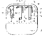
Fig. 6 is the decomposition diagram of the improved razor headstock and blade assembly;
Fig. 7 is the profile of the headstock shown in Figure 6, and it is corresponding with Fig. 5.
Razor head shown in Fig. 1-4 comprises the headstock 1 metal or injection moulding, and it has an elongated bottom 2 and upright end wall 3 on its two relative ends, has only represented an end of the headstock in these figure, the other end and the mirror image relation that becomes.
Headstock supporting 4, two blade assemblies 5 of a cap spare and three pairs of cantilever wire springs 6, its inner (not shown) is fixed on the mid portion of elongated bottom.
Each blade assembly 5 comprise one narrow; blade 7 with sharp knife edges 7A; with the insert supporting device 8 of a shape, on this supporter, be provided with protection part and a leg that hangs from above 12 that 9, one on a platform has crooked skin contact protection curved surface 11 as L type metal stamping sheet.Supporter is along there being a groove 13 in the overwhelming majority of its length, so that form a space between platform 9 and protection part, blade 7 securely is contained on the platform, and its blade 7A stretches out forward in the space in platform the place ahead.
At the end of supporter 8, have lug 14 to upper offset, this lug is connected in its lower section with the upright end portion 6A of spring 6.
Cap spare 4 comprises the supporting member 16 of a tunnel-shaped, and cap moulding 17 is fixed within it.
Cap spare and blade assembly are in their end tightly is stuck in groove on the end wall 3 of the headstock.More specifically, the lug 14 of insert supporting device is embedded in the narrow vertical channel 18, and this groove also is equipped with the vertical ends 6A of corresponding spring 6.On the next door of each groove 18, be a shallow and wide groove 19, its front 21 plays the block effect of the near-end of each leg 12.
Therefore, each blade assembly since its lug 14 be embedded in the groove 18, thereby guide it in the headstock, to move both vertically.Spring 6 gives and being pressed into, therefore, on the normal position, be resting position, blade assembly by the spring rest on its outermost locations, as shown in Figure 3, spring end 6A is directed and is limited in the corresponding groove 18 and moves both vertically, and its upper end is connected with lug 14, and a fulcrum is provided, and the axle that makes blade assembly center on parallel and close each knife-blade rotates.Represent the most clearly that as Fig. 4 this rotational motion is subjected to the restriction of the front 21 of the back of the end of leg 12 and groove 18 and groove 19 respectively.Place the cap spare 4 of blade assembly back by the direction that shaves, be limited and only guide and to move both vertically, promptly be parallel to blade assembly and move accordingly.Cap spare 4 is also shifted onto its outermost locations by its spring 6 separately, as shown in Figure 3.
Shown in Figure 4 is that moving component is in innermost position, and in this position, spring 6 is pressed towards " extreme lower position " of headstock bottom 2.
When using razor, cap spare and blade assembly can be closely differently contoured consistent with the skin in the zone of shaving, this is because they have direction facing to they suffered spring restoring forces, the advantage that can move independently of one another.The independence of these motions can be found out by itself.But apparently, blade assembly also can freely rotate, and the two can closely contact with skin to make each blade assembly keep its blade 7A and the protective surface 11 that contacts skin, thereby has guaranteed it no matter how the skin surface profile changes and still be in optimum state.This is because the rotating shaft of each blade assembly is parallel with the sharp blade of blade, and just in its front.
Fig. 5 is the variation on the overweening contoured skin, and how the position that how to adapt to the fluctuating, particularly blade assembly of skin surface in order to the moving component of explanation razor is regulated automatically and kept contacting of desired and skin.
The transverse movement of blade assembly said it is " vertical " in front, and certainly, this is the specific position of hypothesis razor head.Regardless of the position of razor, the required direction of motion is to traverse the imaginary plane of the skin contact plane that comprises blade and protection part.
Because the protection feature of blade assembly itself, it no longer needs independent guard member usually, still, if having, then can hang with spring and do transverse movement, the mode of similar cap spare.
Certainly, if desired, razor can have a blade assembly, and perhaps three, perhaps more, but two blade assemblies are thought only at present.
Fig. 6 and Fig. 7 illustrate a kind of modified version of the blade assembly and the headstock, and what they were total is same as the previously described embodiments, but some structure has been done improvement, and this will illustrate below.The dash number of improved embodiment increases by 100 than the numbering of the corresponding part of first embodiment.
Blade assembly 105 is actually consistent with first embodiment is described, and just lug 114 is in the identical platform of protection part, need upwards not depart from.Therefore, the rotating shaft of blade assembly " A " is placed in than on the lower position of first embodiment.
The headstock 101 of injection moulding has different structures, and it has the suspension leg 22 of form known, and according to this configuration, the headstock is suitable for detachable, is contained in the upper end of razor handle, and has limited with respect to handle, around the rotational freedom of the longitudinal axis.
There is a upright cylinder 102A on the last plane of bottom 102, it provides a rivet as an integral body of fixing metal spring part, said metal spring comprises the mid portion 106A of a rectangle, spring detent 106 whole with its formation and that longitudinally stretch out is arranged on it, and this spring detent also sticks up the top to the plane of mid portion 106A.
The rear wall of the headstock 101 has a passage, in order to be received in a cap moulding 117 on the fixed position.
In the end wall 103 of the headstock, groove 118 and 119 is complete opening in the above, and separable clip 123 lug 114 by blade assembly is fixed on blade assembly on the knife rest.
The function and the use of blade assembly more than have been described.
Claims (4)
1. razor head; at least can hold two blade assemblies simultaneously; described blade assembly comprises a blade with sharp knife edges; a formation can be installed the supporter of blade platform; blade stretches out forward in the space in platform the place ahead; simultaneously be provided with the protection part that contacts with skin at blade the place ahead one segment distance; described blade assembly also is mounted to and allows each blade to make independently pivoting action in described razor head; it is characterized in that; described insert supporting device is same shape; each supporter has L shaped cross section; establish described platform on the one leg; and the leg of another suspension and described blade leave certain clearance and correspondingly cooperate described razor head limiting the pivot of described blade, and have projection to be contained in the end in each insert supporting device, and described projection can be installed described blade assembly.
2. razor head according to claim 1 is characterized in that described projection engages with spring part.
3. razor head according to claim 2, it is characterized in that: described razor head comprises a razor headstock, it has an elongated bottom that upstanding wall is arranged in its opposite end, the inner surface of described wall has groove, the installation projection that holds described insert supporting device in the described groove, and described spring part is equipped with on the described elongated bottom, described installation projection is upwards being supported in its end, the inner surface of described upstanding wall also has forward and backward bearing-surface, in order to partly to be connected, to limit the rotation of described supporter with supporter.
4. razor head according to claim 2; it is characterized in that: described blade assembly be mounted to make its when shaving by under the active force effect that overcomes the elastic restoring force that described spring part provides with respect to headstock moving linearly, its direction of motion and the imaginary plane traversed by that contacts with skin that comprises described blade and described protection part.
Applications Claiming Priority (2)
| Application Number | Priority Date | Filing Date | Title |
|---|---|---|---|
| GB9006782.8 | 1990-03-27 | ||
| GB909006782A GB9006782D0 (en) | 1990-03-27 | 1990-03-27 | Safety razors and blade units therefor |
Publications (2)
| Publication Number | Publication Date |
|---|---|
| CN1057807A CN1057807A (en) | 1992-01-15 |
| CN1035163C true CN1035163C (en) | 1997-06-18 |
Family
ID=10673307
Family Applications (1)
| Application Number | Title | Priority Date | Filing Date |
|---|---|---|---|
| CN91102479A Expired - Lifetime CN1035163C (en) | 1990-03-27 | 1991-03-26 | Safety razors and blade units therefor |
Country Status (19)
| Country | Link |
|---|---|
| EP (1) | EP0522071B1 (en) |
| JP (1) | JP3085974B2 (en) |
| KR (1) | KR0174756B1 (en) |
| CN (1) | CN1035163C (en) |
| AT (1) | ATE143624T1 (en) |
| AU (1) | AU649665B2 (en) |
| BR (1) | BR9106269A (en) |
| CA (1) | CA2076534C (en) |
| CZ (1) | CZ283054B6 (en) |
| DE (1) | DE69122500T2 (en) |
| DK (1) | DK0522071T3 (en) |
| ES (1) | ES2092564T3 (en) |
| GB (1) | GB9006782D0 (en) |
| GR (1) | GR3021275T3 (en) |
| PL (1) | PL166706B1 (en) |
| RU (1) | RU2091211C1 (en) |
| TR (1) | TR27611A (en) |
| UA (1) | UA25899C2 (en) |
| WO (1) | WO1991014546A1 (en) |
Families Citing this family (18)
| Publication number | Priority date | Publication date | Assignee | Title |
|---|---|---|---|---|
| CA2112888A1 (en) * | 1991-07-18 | 1993-02-04 | Vincent C. Motta | Razor head with variable shaving geometry |
| US5341571A (en) * | 1993-04-16 | 1994-08-30 | American Safety Razor Company | Movable blade shaving cartridge or the like |
| GB9505917D0 (en) * | 1995-03-23 | 1995-05-10 | Gillette Co | Safety razors |
| US5689883A (en) * | 1995-05-08 | 1997-11-25 | Warner-Lambert Company | Shaving implement |
| WO1997035693A2 (en) * | 1996-03-27 | 1997-10-02 | Warner-Lambert Company | Shaving system with uniform shaving forces |
| US6009624A (en) * | 1997-09-30 | 2000-01-04 | The Gillette Company | Razor cartridge with movable blades |
| JP4950506B2 (en) | 2006-02-14 | 2012-06-13 | 株式会社貝印刃物開発センター | razor |
| JP4977374B2 (en) | 2006-02-14 | 2012-07-18 | 株式会社貝印刃物開発センター | razor |
| JP4950507B2 (en) | 2006-02-14 | 2012-06-13 | 株式会社貝印刃物開発センター | razor |
| US8008812B2 (en) | 2006-07-14 | 2011-08-30 | Aurora Office Equipment Co., Ltd. | Paper shredder control system responsive to touch-sensitive element |
| CN201239643Y (en) | 2008-08-06 | 2009-05-20 | 上海震旦办公设备有限公司 | Full automatic paper crusher without selecting paper |
| AU2009296283A1 (en) * | 2008-09-29 | 2010-04-01 | The Gillette Company | Razor cartridges with perforated blade assemblies |
| JP5815409B2 (en) | 2008-12-19 | 2015-11-17 | ビック・バイオレクス・エス・エー | Razor cartridge and mechanical razor provided with the razor cartridge |
| CN101543800A (en) | 2009-05-07 | 2009-09-30 | 上海震旦办公设备有限公司 | Paper jamming prevention protective device of paper shredder |
| EP2454056B1 (en) * | 2009-07-15 | 2014-03-19 | Eveready Battery Company, Inc. | Razor blade technology |
| EP3072646B1 (en) * | 2015-03-25 | 2020-06-17 | The Gillette Company LLC | Shaving razor cartridge |
| CN106098254B (en) * | 2016-07-14 | 2017-08-29 | 广州市明创线缆有限公司 | A kind of manual wringing equipment of cable and its application method |
| CN109514230B (en) * | 2018-12-29 | 2023-06-20 | 温州美葆科技技术有限公司 | Full-automatic assembly equipment for manual shaver and control method thereof |
Citations (3)
| Publication number | Priority date | Publication date | Assignee | Title |
|---|---|---|---|---|
| US4443940A (en) * | 1979-05-25 | 1984-04-24 | The Gillette Company | Safety razor head |
| US4586255A (en) * | 1984-10-15 | 1986-05-06 | The Gillette Company | Razor blade assembly |
| US4932122A (en) * | 1987-12-21 | 1990-06-12 | The Gillette Company | Safety razor blade assembly |
Family Cites Families (3)
| Publication number | Priority date | Publication date | Assignee | Title |
|---|---|---|---|---|
| US4337575A (en) * | 1980-08-07 | 1982-07-06 | The Gillette Company | Razor blade assembly |
| GB2131337B (en) * | 1982-12-07 | 1985-10-30 | Gillette Co | Safety razors |
| US4709477A (en) * | 1986-09-02 | 1987-12-01 | Warner-Lambert Company | Blade assembly featuring variable span |
-
1990
- 1990-03-27 GB GB909006782A patent/GB9006782D0/en active Pending
-
1991
- 1991-03-22 ES ES91907778T patent/ES2092564T3/en not_active Expired - Lifetime
- 1991-03-22 AU AU76532/91A patent/AU649665B2/en not_active Ceased
- 1991-03-22 CA CA002076534A patent/CA2076534C/en not_active Expired - Fee Related
- 1991-03-22 EP EP91907778A patent/EP0522071B1/en not_active Expired - Lifetime
- 1991-03-22 AT AT91907778T patent/ATE143624T1/en not_active IP Right Cessation
- 1991-03-22 UA UA93004086A patent/UA25899C2/en unknown
- 1991-03-22 WO PCT/US1991/001926 patent/WO1991014546A1/en active IP Right Grant
- 1991-03-22 RU SU915053071A patent/RU2091211C1/en active
- 1991-03-22 BR BR919106269A patent/BR9106269A/en not_active IP Right Cessation
- 1991-03-22 KR KR1019920702297A patent/KR0174756B1/en not_active IP Right Cessation
- 1991-03-22 JP JP03507315A patent/JP3085974B2/en not_active Expired - Fee Related
- 1991-03-22 DK DK91907778.4T patent/DK0522071T3/en active
- 1991-03-22 DE DE69122500T patent/DE69122500T2/en not_active Expired - Lifetime
- 1991-03-25 TR TR00294/91A patent/TR27611A/en unknown
- 1991-03-26 PL PL91289588A patent/PL166706B1/en unknown
- 1991-03-26 CN CN91102479A patent/CN1035163C/en not_active Expired - Lifetime
- 1991-03-27 CZ CS91834A patent/CZ283054B6/en unknown
-
1996
- 1996-10-07 GR GR960402631T patent/GR3021275T3/en unknown
Patent Citations (3)
| Publication number | Priority date | Publication date | Assignee | Title |
|---|---|---|---|---|
| US4443940A (en) * | 1979-05-25 | 1984-04-24 | The Gillette Company | Safety razor head |
| US4586255A (en) * | 1984-10-15 | 1986-05-06 | The Gillette Company | Razor blade assembly |
| US4932122A (en) * | 1987-12-21 | 1990-06-12 | The Gillette Company | Safety razor blade assembly |
Also Published As
| Publication number | Publication date |
|---|---|
| AU649665B2 (en) | 1994-06-02 |
| GR3021275T3 (en) | 1997-01-31 |
| ATE143624T1 (en) | 1996-10-15 |
| ES2092564T3 (en) | 1996-12-01 |
| JPH05505746A (en) | 1993-08-26 |
| CA2076534A1 (en) | 1991-09-28 |
| BR9106269A (en) | 1993-04-13 |
| DE69122500T2 (en) | 1997-04-03 |
| KR930700267A (en) | 1993-03-13 |
| GB9006782D0 (en) | 1990-05-23 |
| TR27611A (en) | 1995-06-13 |
| WO1991014546A1 (en) | 1991-10-03 |
| PL166706B1 (en) | 1995-06-30 |
| AU7653291A (en) | 1991-10-21 |
| CA2076534C (en) | 1998-10-06 |
| EP0522071A4 (en) | 1993-05-19 |
| RU2091211C1 (en) | 1997-09-27 |
| CS9100834A2 (en) | 1991-11-12 |
| DE69122500D1 (en) | 1996-11-07 |
| CZ283054B6 (en) | 1997-12-17 |
| JP3085974B2 (en) | 2000-09-11 |
| UA25899C2 (en) | 1999-02-26 |
| KR0174756B1 (en) | 1999-02-18 |
| EP0522071A1 (en) | 1993-01-13 |
| DK0522071T3 (en) | 1997-02-17 |
| CN1057807A (en) | 1992-01-15 |
| EP0522071B1 (en) | 1996-10-02 |
Similar Documents
| Publication | Publication Date | Title |
|---|---|---|
| CN1035163C (en) | Safety razors and blade units therefor | |
| US5416974A (en) | Safety razors and blade units therefor | |
| CN1135155C (en) | Razor blade assembly | |
| CN1033011C (en) | Razor | |
| KR900002294B1 (en) | Blade assembly featuring variable span | |
| EP1646481B1 (en) | Safety razors | |
| US6397473B1 (en) | Shaving system with uniform shaving forces | |
| RU98120352A (en) | Razor Blades | |
| US20030159291A1 (en) | Shaving system with uniform shaving forces | |
| CA2190269C (en) | Safety razors | |
| CN1130889A (en) | Shaving apparatus | |
| WO1995004637A1 (en) | Dynamic shaving system | |
| GB2360479A (en) | Improvements in or relating to a razor |
Legal Events
| Date | Code | Title | Description |
|---|---|---|---|
| C06 | Publication | ||
| PB01 | Publication | ||
| C10 | Entry into substantive examination | ||
| SE01 | Entry into force of request for substantive examination | ||
| C14 | Grant of patent or utility model | ||
| GR01 | Patent grant | ||
| C15 | Extension of patent right duration from 15 to 20 years for appl. with date before 31.12.1992 and still valid on 11.12.2001 (patent law change 1993) | ||
| OR01 | Other related matters | ||
| AV01 | Patent right actively abandoned | ||
| AV01 | Patent right actively abandoned | ||
| C20 | Patent right or utility model deemed to be abandoned or is abandoned |