CN1059610C - 具有可变喷雾方式的喷雾器 - Google Patents
具有可变喷雾方式的喷雾器 Download PDFInfo
- Publication number
- CN1059610C CN1059610C CN95117279A CN95117279A CN1059610C CN 1059610 C CN1059610 C CN 1059610C CN 95117279 A CN95117279 A CN 95117279A CN 95117279 A CN95117279 A CN 95117279A CN 1059610 C CN1059610 C CN 1059610C
- Authority
- CN
- China
- Prior art keywords
- mentioned
- sprayer
- piston rod
- stopper head
- hole
- Prior art date
- Legal status (The legal status is an assumption and is not a legal conclusion. Google has not performed a legal analysis and makes no representation as to the accuracy of the status listed.)
- Expired - Fee Related
Links
Images


Classifications
-
- B—PERFORMING OPERATIONS; TRANSPORTING
- B05—SPRAYING OR ATOMISING IN GENERAL; APPLYING FLUENT MATERIALS TO SURFACES, IN GENERAL
- B05B—SPRAYING APPARATUS; ATOMISING APPARATUS; NOZZLES
- B05B11/00—Single-unit hand-held apparatus in which flow of contents is produced by the muscular force of the operator at the moment of use
-
- B—PERFORMING OPERATIONS; TRANSPORTING
- B05—SPRAYING OR ATOMISING IN GENERAL; APPLYING FLUENT MATERIALS TO SURFACES, IN GENERAL
- B05B—SPRAYING APPARATUS; ATOMISING APPARATUS; NOZZLES
- B05B1/00—Nozzles, spray heads or other outlets, with or without auxiliary devices such as valves, heating means
- B05B1/34—Nozzles, spray heads or other outlets, with or without auxiliary devices such as valves, heating means designed to influence the nature of flow of the liquid or other fluent material, e.g. to produce swirl
- B05B1/3405—Nozzles, spray heads or other outlets, with or without auxiliary devices such as valves, heating means designed to influence the nature of flow of the liquid or other fluent material, e.g. to produce swirl to produce swirl
- B05B1/341—Nozzles, spray heads or other outlets, with or without auxiliary devices such as valves, heating means designed to influence the nature of flow of the liquid or other fluent material, e.g. to produce swirl to produce swirl before discharging the liquid or other fluent material, e.g. in a swirl chamber upstream the spray outlet
- B05B1/3478—Nozzles, spray heads or other outlets, with or without auxiliary devices such as valves, heating means designed to influence the nature of flow of the liquid or other fluent material, e.g. to produce swirl to produce swirl before discharging the liquid or other fluent material, e.g. in a swirl chamber upstream the spray outlet the liquid flowing at least two different courses before reaching the swirl chamber
-
- B—PERFORMING OPERATIONS; TRANSPORTING
- B05—SPRAYING OR ATOMISING IN GENERAL; APPLYING FLUENT MATERIALS TO SURFACES, IN GENERAL
- B05B—SPRAYING APPARATUS; ATOMISING APPARATUS; NOZZLES
- B05B1/00—Nozzles, spray heads or other outlets, with or without auxiliary devices such as valves, heating means
- B05B1/34—Nozzles, spray heads or other outlets, with or without auxiliary devices such as valves, heating means designed to influence the nature of flow of the liquid or other fluent material, e.g. to produce swirl
- B05B1/3405—Nozzles, spray heads or other outlets, with or without auxiliary devices such as valves, heating means designed to influence the nature of flow of the liquid or other fluent material, e.g. to produce swirl to produce swirl
- B05B1/341—Nozzles, spray heads or other outlets, with or without auxiliary devices such as valves, heating means designed to influence the nature of flow of the liquid or other fluent material, e.g. to produce swirl to produce swirl before discharging the liquid or other fluent material, e.g. in a swirl chamber upstream the spray outlet
- B05B1/3421—Nozzles, spray heads or other outlets, with or without auxiliary devices such as valves, heating means designed to influence the nature of flow of the liquid or other fluent material, e.g. to produce swirl to produce swirl before discharging the liquid or other fluent material, e.g. in a swirl chamber upstream the spray outlet with channels emerging substantially tangentially in the swirl chamber
- B05B1/3431—Nozzles, spray heads or other outlets, with or without auxiliary devices such as valves, heating means designed to influence the nature of flow of the liquid or other fluent material, e.g. to produce swirl to produce swirl before discharging the liquid or other fluent material, e.g. in a swirl chamber upstream the spray outlet with channels emerging substantially tangentially in the swirl chamber the channels being formed at the interface of cooperating elements, e.g. by means of grooves
- B05B1/3436—Nozzles, spray heads or other outlets, with or without auxiliary devices such as valves, heating means designed to influence the nature of flow of the liquid or other fluent material, e.g. to produce swirl to produce swirl before discharging the liquid or other fluent material, e.g. in a swirl chamber upstream the spray outlet with channels emerging substantially tangentially in the swirl chamber the channels being formed at the interface of cooperating elements, e.g. by means of grooves the interface being a plane perpendicular to the outlet axis
-
- B—PERFORMING OPERATIONS; TRANSPORTING
- B05—SPRAYING OR ATOMISING IN GENERAL; APPLYING FLUENT MATERIALS TO SURFACES, IN GENERAL
- B05B—SPRAYING APPARATUS; ATOMISING APPARATUS; NOZZLES
- B05B11/00—Single-unit hand-held apparatus in which flow of contents is produced by the muscular force of the operator at the moment of use
- B05B11/0005—Components or details
- B05B11/0027—Means for neutralising the actuation of the sprayer ; Means for preventing access to the sprayer actuation means
- B05B11/0029—Valves not actuated by pressure
-
- B—PERFORMING OPERATIONS; TRANSPORTING
- B05—SPRAYING OR ATOMISING IN GENERAL; APPLYING FLUENT MATERIALS TO SURFACES, IN GENERAL
- B05B—SPRAYING APPARATUS; ATOMISING APPARATUS; NOZZLES
- B05B11/00—Single-unit hand-held apparatus in which flow of contents is produced by the muscular force of the operator at the moment of use
- B05B11/01—Single-unit hand-held apparatus in which flow of contents is produced by the muscular force of the operator at the moment of use characterised by the means producing the flow
- B05B11/10—Pump arrangements for transferring the contents from the container to a pump chamber by a sucking effect and forcing the contents out through the dispensing nozzle
- B05B11/1001—Piston pumps
- B05B11/1005—Piston pumps with means for adjusting or modifying pump stroke
- B05B11/1008—Piston pumps with means for adjusting or modifying pump stroke by adjusting or modifying the pump end-of-dispensing-stroke position
-
- B—PERFORMING OPERATIONS; TRANSPORTING
- B05—SPRAYING OR ATOMISING IN GENERAL; APPLYING FLUENT MATERIALS TO SURFACES, IN GENERAL
- B05B—SPRAYING APPARATUS; ATOMISING APPARATUS; NOZZLES
- B05B1/00—Nozzles, spray heads or other outlets, with or without auxiliary devices such as valves, heating means
- B05B1/12—Nozzles, spray heads or other outlets, with or without auxiliary devices such as valves, heating means capable of producing different kinds of discharge, e.g. either jet or spray
Abstract
一种喷雾方式能够变化的喷雾器,它由于设置了第二液体流道,部分地降低了自旋速度,所以能喷射出喷雾锥窄的喷雾。在自旋探头中的一个孔造成了与排出通道相通的第二液体流道,它可以随着柱塞相对于空心活塞杆的转动而有选择地打开或关闭。
Description
本发明一般地涉及一种细雾喷雾器,它有一根作往复运动的空心的活塞杆,一个用手指按压的柱塞安装在该活塞杆上面,用来泵出液体。设置了某种公知的自旋机构,以便在液体通过排出小孔呈细雾状喷雾锥喷出时具有一定的旋转或涡旋速度。
更具体的说,本发明涉及建立一条第二液体流道,用以使一些从排出通道通向自旋机构的液体分流,降低一些自旋的速度,从而使喷雾呈较窄的喷雾锥的喷雾器。上述第二液体流道可以有选择地打开或关闭,以便调整喷雾锥的大小。
公知的泵压喷雾器通常具有某种类型的自旋机构,用来给液体造成一定速度的自旋或涡旋,使液体通过排出小孔以细雾状喷射出去,喷射出去的液体在大气中分散成一定大小的扩散的喷雾锥。为此,带小孔的盖上有一个与排出小孔同轴线的自旋腔,和通到该自旋腔的切向槽。在柱头或探头与围绕着它的带小孔的盖之间形成了通到切向槽的纵向槽,以建立一条从空心活塞杆中形成的排出通道开始的流道。上述带小孔的盖和探头装在一个柱塞头内,该柱塞头与活塞杆联结,以便在用手指按压柱塞头时使活塞杆作往复运动。
在有些使用场合,希望利用现有的自旋机构形成较窄的喷雾锥,上述扩散得较小的喷雾锥适合于在喷雾操作中对着给定尺寸的小区域目标的要求。
此外,如果能有选择地以简单而有效的方式利用现有的喷雾机构改变喷雾锥的大小,而不使结构复杂化,也不需要额外的模制零件,就更加有利。
本发明的目的就是提供一种改进了的细雾喷雾器,它能够以简单而有效,而且效率很高的方式,降低通向喷雾小孔的液体的切向速度,喷射出一束比普通的喷雾器喷出来的喷雾扩散得小的较窄的喷雾。
根据这一总的目的,在普通的指压喷雾器的自旋探头上,有一个通过设置在活塞杆上的孔与活塞杆上的排出通道相通的通孔,以建立通到自旋腔切向槽的下游端去的第二液体通道。液体从排出通道按照普通的方式流过第一液体流道,并在自旋腔内以给定的速度进行自旋。一部分液体从排出通道分流到第二液体流道内,降低了一些液体在自旋腔内的自旋速度,从而使从小孔中喷射出来的喷雾具有较窄的扩散得较小的喷雾锥。
上述柱塞头能绕着活塞杆在两个位置上转动,一个是探头与活塞杆的孔错开的位置,以便使液体只能通过第一流道喷出,形成一个具有给定的自旋速度的细雾喷雾;另一个是探头与活塞杆的孔对准的位置,以便使液体能够从排出通道通过两个液体流道喷射出去,形成自旋速度降低的,喷雾锥较窄的喷雾。
在泵压喷雾器上的活塞杆与容器罩之间起作用的协同工作的装置,阻止活塞杆随着柱塞头转动。
在活塞杆与柱塞头之间起作用的挡块装置,使柱塞头的转动被限制在错开和对准这两个位置上。
此外,还可以在柱塞头和/或容器罩上设置限制活塞杆的往复运动行程的限位挡块,以限制喷雾器的喷射量。
下面,参照附图详细描述本发明,本发明的其他目的、优点和新颖的特点将变得更加明显。附图中:
图1是按照本发明的细雾喷雾器的局部垂直断面图;
图2是图1中经过改进的活塞杆的局部垂直断面图;
图3是沿图1中3-3线的断面图;
图4是沿图1中4-4线的断面图;
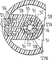
图5是沿图1中5-5线的断面图;
图6是与图5相似的视图,表示柱塞头相对于活塞杆转动了一个角度;
图7是活塞杆上端的局部视图,表示开设在活塞杆上的一个孔的实施例;
图8是与图7相似的视图,表示在活塞杆上端开设的一个孔的另一个实施例。
请参阅附图,在所有的图中,同样的标号表示同样的零件。图1中的泵压喷雾器用标号10表示,它有一个用来把喷雾器安装在容器(图中未表示)上的容器罩11,上述容器是用来装要喷雾的液体的。
泵的活塞的空心活塞杆12穿过容器罩冠状部分13的中心孔,以便用通常的方式在泵的缸(图中未表示)内作往复运动。柱塞头14装在活塞杆上,当在柱塞头上用手指对指压板15施加向下的压力,克服活塞回程弹簧(图中未表示)的弹力时,就能使活塞作往复运动。
空心活塞杆中有一条液体排出通道16,它的上端与柱塞头14中的横向通道17相通。
柱塞头上有一个旋转探头18,一个具有同轴线排料孔21的喷嘴盖19围绕在旋转探头的周围。
在带孔杯内部的前表面上有一种公知的自旋机构,该机构包括许多条切向槽22(图1中只表示了一条),这些切向槽的下游端终止在中央自旋腔或涡旋腔23中。在喷嘴盖和探头18之间形成的纵向槽24与切向槽22相通,并与一个环形孔和横向通道17一起形成第一流道,这条流道与通道16相通。在本申请人所共同拥有的美国专利4,074,861中,详细描述了上述自旋机构和第一流道的构造。
在泵压工作过程中,液体通过通道16和第一流道,借助于自旋机构呈细雾状喷出,该自旋机构使液体在通过排出孔喷出时获得一定速度的涡旋或旋转,而作涡旋运动的液体颗粒在大气中被打碎,扩散成一定锥形的喷雾锥。
按照本发明,可以使自旋的速度降低一些,以便产生较窄的喷雾锥。这可以用在探头18上设置一个从自旋腔23上的切向槽22下游的端部延伸到活塞杆12的孔26来实现。活塞杆上至少设有一个开口27。在图1和图5的位置上,上述开口27与孔26对准,形成与通道16相通的第二流道。
当泵压处在如图1和图5所示的相对于活塞杆的位置上的柱塞,使它作往复运动时,液体便通过通道16与第一流道17、25、24,以一定的速度在自旋腔23内作涡旋运动之后被喷射出来。在上述泵压过程中,有一些液体从通道16分流到为降低一些在自旋腔23中的切向速度的第二流道27、26内,以使经过分流以后通过小孔21喷射出来的液体,具有比只通过通道16和第一流道所喷射出来的喷雾锥体更窄的锥形尺寸。
当柱塞头绕活塞杆从图5的孔26与27对准的位置,转到图6中孔26不与孔27对准的位置时,液体通过第二流道的所有分流都被堵住了,液体只能通过第一流道扩散成正常的喷雾锥形喷射出去,这个正常的锥形是由切向槽给液体造成的最高旋转速度所决定的。
为了在柱塞头转动时阻止活塞杆12转动,活塞杆上有一条或者三条外纵向肋28(图3中表示有三条),肋的形状与从罩11的冠状部分13悬垂下来的中心套筒30上的纵向槽29(图4)的形状相配合。
此外,还设置了限制柱塞头在图5和图6的位置上作相对转动的限位挡块。这种限位挡块可以是从柱塞头的内裙部33的壁32沿径向向内延伸的,等间隔的凸块31。在图5的位置上,活塞杆的各条肋28的上端与凸块31的一侧接触,而在柱塞头转动到图6的位置上时,肋28的上端与凸块31的另一侧接触。
应该指出,图中虽然只有孔27在柱塞头转动时与孔26对准或错开,但仍开设了其的孔27A、27B。孔27、27A、27B是等间隔的,设置孔27A、27B是为了便于柱塞头和活塞杆的分组装,在组装时不需要做标记。这样,由于有三个孔27,三个凸块31和三条肋28,柱塞头与活塞杆装配时最初的方位可以定在图5的位置上,也可以定在图6的位置上,而不需要做复杂的标记。
如图7所示,各孔27可以是一个开口的缺口,具有隔开的,互相平行的两个侧面。或者,如图8所示,可以在活塞杆的上端形成这样一个缺口33,这个缺口有倾斜的底面34,以便在柱塞头发生相对转动时部分堵住而部分打开孔26。这样,在图8的实施例中,上述第二流道就能在完全堵住的位置和一个逐渐打开的位置之间进行工作,以便在一个范围内改变喷雾的锥形,这个范围就是图5中柱塞头与活塞杆的缺口完全对准的位置,和图6中完全错开的位置。
本发明的另一个特点是设置了限位挡块,用来限制活塞杆的往复运动,从而限定从小孔喷雾出去的体积。为此,可以在裙边33上设置悬垂支脚35和/或在罩11的冠状部分13上设置突出支脚36。如果支脚35的方向与支脚36对准,那么它就会在柱塞头向下运动时靠在支脚36的端部,从而限制活塞的往复运动,也就是限定喷雾器的喷射量。如果只设置支脚35,那么就只有在它们靠住冠状部分13时才限制柱塞头和活塞的向下运动。如果只设置支脚36,那么就只有在它们靠住套筒33的底面时才限制柱塞头和活塞的向下运动。
显然,按照上述教导可以对本发明作出许多改进和变化。例如,可以在本发明的范围内设置与图中和说明书中所描述的不同的自旋机构。还可以设置其他的与肋28和槽29不同的,在柱塞转动时阻止活塞杆转动的装置。
因此就能够理解,本发明可以用不同于专门描述的实施例的方式来实施。
Claims (25)
1.一种泵压喷雾器,它具有一根能在容器罩内作往复泵压运动的空心活塞杆,活塞杆中有一条液体排出通道;一个装在上述活塞杆上、具有从活塞杆的横向延伸出去的探头的柱塞头;一个围绕着上述探头的喷嘴盖,上述喷嘴盖有一个喷射小孔和与上述小孔相通的自旋腔,用来使通过上述小孔喷射出去的液体获得一定的自旋速度,以预定的喷雾锥形呈细雾状喷射出去;上述柱塞头和喷嘴盖具有从上述排出通道经过上述液体从中穿过的自旋腔到达上述小孔的第一流道;其特征在于:
上述探头具有一形成第二通道的开口,该第二通道从上述液体排出通道连通到上述自旋腔,从而同样也可把液体从所述液体排出通道经所述探头上的开口引到所述自旋腔,用来降低自旋的速度,以便产生一个比预定的喷雾锥形窄的喷雾锥形。
2.如权利要求1所述的喷雾器,其特征在于,上述柱塞头能在上述活塞杆上绕其中心轴线相对转动,
上述活塞杆上端的外表面具有至少一个能与上述探头中的孔对准和错开的孔,以便根据柱塞头相对转动后的位置,打开或者堵住上述探头上的孔。
3.如权利要求2所述的喷雾器,其特征在于,上述活塞杆上的孔是一个具有预定宽度的缺口。
4.如权利要求2所述的喷雾器,其特征在于,上述活塞杆上的孔是一个缺口,这个缺口具有倾斜的下边缘,以便在上述柱塞头转动时,逐渐打开上述探头上的孔,从而逐渐调整喷雾锥的尺寸。
5.如权利要求2所述的喷雾器,其特征在于,在上述活塞杆与上述罩之间设有协同工作的装置,以便阻止上述活塞杆随着上述柱塞头转动。
6.如权利要求2所述的喷雾器,其特征在于,在上述柱塞头与上述活塞杆之间设有协同工作的挡块装置,用来限制柱塞头,使它在上述活塞杆的孔与上述探头的孔对准与错开的位置上转动。
7.如权利要求1所述的喷雾器,其特征在于,在上述柱塞头上设有第一限位挡块,用来限制活塞杆的往复运动,以控制上述喷雾器在上述柱塞头在既定转动位置上的喷雾量。
8.如权利要求7所述的喷雾器,其特征在于,上述第一限位挡块包括至少一个与上述罩接触的悬垂支脚。
9.如权利要求7所述的喷雾器,其特征在于,在上述罩上设有用来让上述第一限位挡块靠住的第二限位挡块,用来限制活塞杆的往复运动。
10.如权利要求9所述的喷雾器,其特征在于,上述第二限位挡块具有至少一个在上述罩上的突出支脚。
11.如权利要求5所述的喷雾器,其特征在于,上述协同工作的装置是在上述活塞杆和罩上沿纵向延伸的肋和槽。
12.如权利要求6所述的喷雾器,其特征在于,上述挡块装置包括在上述柱塞头上沿径向延伸的隔开的凸块,和在上述活塞杆上的沿径向延伸的隔开的肋。
13.如权利要求12所述的喷雾器,其特征在于,上述肋与设置在上述罩上的相应的槽相配合,以阻止活塞杆在活塞杆转动时跟着转动。
14.一种泵压喷雾器,它包括:
一根空心活塞杆,它能在一个容器罩内作往复运动,并有一条排出液体的通道;
一个柱塞头,它装在上述活塞杆上,具有液体喷雾装置和从上述排出液体的通道连通到喷雾装置的第一流道;
上述喷雾装置包括一个自旋探头,该探头有一个终接于上述活塞杆的通孔;
上述活塞杆至少有一个与上述排出液体的通道相通的孔;
上述柱塞头能绕着上述活塞杆转动到与上述孔错开的位置,以便使液体只通过上述第一流道从上述通道喷射出去,产生给定自旋速度的液体喷雾;
上述柱塞头能绕着上述活塞杆转动到与上述孔对准的位置,以便使液体能通过上述两个流道从上述通道喷射出去,产生一个切线速度比上述给定速度小,并且喷雾锥小的液体喷雾。
15.如权利要求14所述的喷雾器,其特征在于,上述活塞杆的孔包括至少一个有一定宽度的缺口。
16.如权利要求14所述的喷雾器,其特征在于,上述活塞杆的孔是一个底面倾斜的缺口,以便在柱塞头转动时逐渐与上述探头的孔对准,来逐渐调整喷雾锥的大小。
17.如权利要求14所述的喷雾器,其特征在于,在上述活塞杆和罩上设有阻止活塞杆随着柱塞头转动的协同工作的装置。
18.如权利要求17所述的喷雾器,其特征在于,上述协同工作的装置是相配的肋和槽。
19.如权利要求14所述的喷雾器,其特征在于,在上述活塞杆和柱塞头上设有限制柱塞头转动到上述错开位置和对准位置为止的,协同工作的挡块装置。
20.如权利要求18所述的喷雾器,其特征在于,上述肋设在上述活塞杆上,而上述用来与肋接触的凸块设在上述柱塞头上,以便限制柱塞头转动到上述错开位置和对准位置为止。
21.如权利要求19所述的喷雾器,其特征在于,上述挡块装置是径向隔开的协同工作的凸块。
22.如权利要求14所述的喷雾器,其特征在于,在上述柱塞头上设有至少一个第一限位挡块,以限制上述活塞杆的往复运动的行程,从而限制喷雾量。
23.如权利要求22所述的喷雾器,其特征在于,上述第一限位挡块是用来与上述罩相碰的悬垂凸块。
24.如权利要求14所述的喷雾器,其特征在于,在上述着罩上至少设有一个第二挡块,用来限制上述活塞杆往复运动的行程,从而限制喷雾量。
25.如权利要求24所述的喷雾器,其特征在于,上述第二限位挡块是用来与上述罩相碰的突出的凸块。
Applications Claiming Priority (3)
| Application Number | Priority Date | Filing Date | Title |
|---|---|---|---|
| US08/326,230 | 1994-10-20 | ||
| US08/326230 | 1994-10-20 | ||
| US08/326,230 US5547132A (en) | 1994-10-20 | 1994-10-20 | Sprayer having variable spray pattern |
Publications (2)
| Publication Number | Publication Date |
|---|---|
| CN1127681A CN1127681A (zh) | 1996-07-31 |
| CN1059610C true CN1059610C (zh) | 2000-12-20 |
Family
ID=23271359
Family Applications (1)
| Application Number | Title | Priority Date | Filing Date |
|---|---|---|---|
| CN95117279A Expired - Fee Related CN1059610C (zh) | 1994-10-20 | 1995-10-10 | 具有可变喷雾方式的喷雾器 |
Country Status (11)
| Country | Link |
|---|---|
| US (1) | US5547132A (zh) |
| EP (1) | EP0707893B1 (zh) |
| JP (1) | JP3219362B2 (zh) |
| KR (1) | KR100375238B1 (zh) |
| CN (1) | CN1059610C (zh) |
| AU (1) | AU691965B2 (zh) |
| BR (1) | BR9503199A (zh) |
| CA (1) | CA2160964C (zh) |
| DE (1) | DE69516794T2 (zh) |
| ES (1) | ES2145219T3 (zh) |
| TW (1) | TW364862B (zh) |
Families Citing this family (25)
| Publication number | Priority date | Publication date | Assignee | Title |
|---|---|---|---|---|
| US5738282A (en) * | 1996-03-20 | 1998-04-14 | Calmar Inc. | Pump sprayer nozzle for producing a solid spray pattern |
| FR2772644B1 (fr) * | 1997-12-24 | 2000-02-04 | D Investissement Ind Et Commer | Buse de pulverisation a moyen statique d'inhibition d'ecoulement |
| DE10064630A1 (de) * | 2000-12-22 | 2002-06-27 | Pfeiffer Erich Gmbh & Co Kg | Spender für Medien |
| US7114666B2 (en) | 2002-12-10 | 2006-10-03 | Water Pik, Inc. | Dual massage shower head |
| KR100995652B1 (ko) * | 2003-08-28 | 2010-11-22 | 주식회사 종우실업 | 예압식 저형상 미세 수동 분사펌프 |
| JP4511856B2 (ja) * | 2004-03-22 | 2010-07-28 | 株式会社三谷バルブ | 噴出装置、および噴出器 |
| GB0515592D0 (en) | 2005-07-28 | 2005-09-07 | Glaxo Group Ltd | Nozzle for a nasal inhaler |
| DE102005037972A1 (de) * | 2005-08-11 | 2007-02-22 | Krauss-Maffei Kunststofftechnik Gmbh | Düse für Sprühkopf |
| US8345931B2 (en) * | 2006-02-10 | 2013-01-01 | The Western Union Company | Biometric based authorization systems for electronic fund transfers |
| AU2008257489C1 (en) * | 2007-05-30 | 2014-07-03 | Glaxo Group Limited | Fluid dispenser |
| CA2820623C (en) | 2012-06-22 | 2017-10-03 | Water Pik, Inc. | Bracket for showerhead with integral flow control |
| WO2014201420A1 (en) | 2013-06-13 | 2014-12-18 | Water Pik, Inc. | Showerhead with turbine driven shutter |
| CN103738593B (zh) * | 2013-12-20 | 2016-08-17 | 中山市美捷时包装制品有限公司 | 一种可调节流量自锁喷盖 |
| KR20150112650A (ko) * | 2014-03-28 | 2015-10-07 | 이은석 | 슬라이딩타입 펌핑장치 |
| AR101397A1 (es) | 2014-08-06 | 2016-12-14 | Johnson & Son Inc S C | Inserto para pulverizadores |
| KR101708749B1 (ko) * | 2014-12-04 | 2017-02-21 | 주식회사 모소 | 미세 분사 노즐을 갖는 용액 분사 유닛 |
| CA3084565A1 (en) | 2016-02-01 | 2017-08-10 | Water Pik, Inc. | Handheld pet spray wand |
| USD803981S1 (en) | 2016-02-01 | 2017-11-28 | Water Pik, Inc. | Handheld spray nozzle |
| US10265710B2 (en) | 2016-04-15 | 2019-04-23 | Water Pik, Inc. | Showerhead with dual oscillating massage |
| USD970684S1 (en) | 2016-04-15 | 2022-11-22 | Water Pik, Inc. | Showerhead |
| WO2018049213A1 (en) | 2016-09-08 | 2018-03-15 | Water Pik, Inc. | Pause assembly for showerheads |
| USD843549S1 (en) | 2017-07-19 | 2019-03-19 | Water Pik, Inc. | Handheld spray nozzle |
| JP6783732B2 (ja) * | 2017-09-15 | 2020-11-11 | 株式会社東芝 | 画像処理装置および画像処理方法 |
| USD872227S1 (en) | 2018-04-20 | 2020-01-07 | Water Pik, Inc. | Handheld spray device |
| FR3090596B1 (fr) * | 2018-12-20 | 2021-01-08 | Albea Services | Systeme de fixation pour le montage d’une pompe de distribution sur un flacon et flacon de produit fluide associe |
Citations (2)
| Publication number | Priority date | Publication date | Assignee | Title |
|---|---|---|---|---|
| GB2261389A (en) * | 1991-11-15 | 1993-05-19 | Nabil Ghattas Sarraf | Fluid dispensing apparatus |
| US5284276A (en) * | 1992-10-21 | 1994-02-08 | Bespak Plc | Pump dispenser with combined inlet and outlet ports |
Family Cites Families (21)
| Publication number | Priority date | Publication date | Assignee | Title |
|---|---|---|---|---|
| US1097788A (en) * | 1913-06-05 | 1914-05-26 | Alvan B Brown | Sprayer. |
| US1202051A (en) * | 1915-01-04 | 1916-10-24 | Gerald R Cushman | Spraying-nozzle. |
| US2323001A (en) * | 1939-06-08 | 1943-06-29 | Bargeboer Adolf | Liquid spraying device for liquid fuel burners |
| BE561228A (zh) * | 1956-10-01 | E Robert Fred Vauthier & Cie Ets | ||
| US3061203A (en) * | 1960-09-15 | 1962-10-30 | Kitabayashi Seiichi | Device for emitting painting material |
| US3112074A (en) * | 1961-11-29 | 1963-11-26 | Edward Howard Green | Spray head for an aerosol dispenser |
| US3129893A (en) * | 1962-05-31 | 1964-04-21 | Edward Howard Green | Spray head for swirling spray |
| US3638867A (en) * | 1970-09-14 | 1972-02-01 | Risdon Mfg Co | Variable discharge aerosol spray nozzle |
| US3804296A (en) * | 1972-04-27 | 1974-04-16 | Gillette Co | Adjustable aerosol valve button assembly |
| US3994442A (en) * | 1975-04-07 | 1976-11-30 | Seaquist Valve Company, Div. Of Pittway Corporation | Solid pattern mbu button |
| US4051983B1 (en) * | 1975-11-19 | 1993-12-14 | Calmar Inc. | Pump sprayer having pump priming means |
| US4074861A (en) * | 1976-06-18 | 1978-02-21 | Realex Corporation | Spray pattern control structure and method |
| IN148848B (zh) * | 1977-03-02 | 1981-06-27 | Abplanalp Robert H | |
| US4179049A (en) * | 1977-04-29 | 1979-12-18 | Avon Products, Inc. | Pump dispenser |
| US4109869A (en) * | 1977-06-16 | 1978-08-29 | Dutton-Lainson Company | Oiler with adjustable spray nozzle |
| DE2733102A1 (de) * | 1977-07-22 | 1979-02-01 | Bayer Ag | Verfahren und vorrichtung zum zerstaeuben von fluessigkeiten |
| US4247048A (en) * | 1979-03-29 | 1981-01-27 | Ethyl Corporation | Dispensing nozzle |
| US4311256A (en) * | 1980-06-02 | 1982-01-19 | Diamond International Corporation | Mechanical breakup actuator |
| US4735346A (en) * | 1985-08-29 | 1988-04-05 | Stoody William R | Child resistant valving nozzle |
| US4706888A (en) * | 1986-07-11 | 1987-11-17 | Calmar, Inc. | Multi-purpose nozzle assembly |
| CA2129513C (en) * | 1992-02-07 | 1999-12-28 | James L. Drobish | Spray pump package employing multiple orifices for dispensing liquid in different spray patterns with automatically adjusted optimized pump stroke for each pattern |
-
1994
- 1994-10-20 US US08/326,230 patent/US5547132A/en not_active Expired - Lifetime
-
1995
- 1995-07-19 TW TW084107491A patent/TW364862B/zh not_active IP Right Cessation
- 1995-07-28 DE DE69516794T patent/DE69516794T2/de not_active Expired - Fee Related
- 1995-07-28 EP EP95305306A patent/EP0707893B1/en not_active Expired - Lifetime
- 1995-07-28 ES ES95305306T patent/ES2145219T3/es not_active Expired - Lifetime
- 1995-08-17 JP JP23199295A patent/JP3219362B2/ja not_active Expired - Fee Related
- 1995-08-23 BR BR9503199A patent/BR9503199A/pt not_active IP Right Cessation
- 1995-10-10 CN CN95117279A patent/CN1059610C/zh not_active Expired - Fee Related
- 1995-10-17 KR KR1019950035849A patent/KR100375238B1/ko not_active IP Right Cessation
- 1995-10-18 AU AU34305/95A patent/AU691965B2/en not_active Ceased
- 1995-10-19 CA CA002160964A patent/CA2160964C/en not_active Expired - Fee Related
Patent Citations (2)
| Publication number | Priority date | Publication date | Assignee | Title |
|---|---|---|---|---|
| GB2261389A (en) * | 1991-11-15 | 1993-05-19 | Nabil Ghattas Sarraf | Fluid dispensing apparatus |
| US5284276A (en) * | 1992-10-21 | 1994-02-08 | Bespak Plc | Pump dispenser with combined inlet and outlet ports |
Also Published As
| Publication number | Publication date |
|---|---|
| CA2160964A1 (en) | 1996-04-21 |
| CN1127681A (zh) | 1996-07-31 |
| KR100375238B1 (ko) | 2003-04-21 |
| TW364862B (en) | 1999-07-21 |
| ES2145219T3 (es) | 2000-07-01 |
| AU3430595A (en) | 1996-05-02 |
| JPH08117651A (ja) | 1996-05-14 |
| EP0707893B1 (en) | 2000-05-10 |
| EP0707893A2 (en) | 1996-04-24 |
| BR9503199A (pt) | 1997-05-27 |
| CA2160964C (en) | 2001-12-25 |
| US5547132A (en) | 1996-08-20 |
| DE69516794D1 (de) | 2000-06-15 |
| DE69516794T2 (de) | 2001-02-01 |
| AU691965B2 (en) | 1998-05-28 |
| MX9504420A (es) | 1998-11-30 |
| KR960013480A (ko) | 1996-05-22 |
| JP3219362B2 (ja) | 2001-10-15 |
| EP0707893A3 (en) | 1997-01-29 |
Similar Documents
| Publication | Publication Date | Title |
|---|---|---|
| CN1059610C (zh) | 具有可变喷雾方式的喷雾器 | |
| US5183186A (en) | Spray dispensing device having a tapered mixing chamber | |
| EP0729792B1 (en) | Sprayer having variable spray pattern | |
| JP2597410B2 (ja) | 引き金式噴霧器用のバレルスクリーンインサートを有するフォームオフ・ノズル構造 | |
| US2974880A (en) | Aerosol spray head | |
| KR100504082B1 (ko) | 수동펌프스프레이어 | |
| US6050504A (en) | Spray dispensing device using swirl passages and using the Bernoulli effect | |
| JPH08238445A (ja) | 放出変更可能なポンプ式噴霧器 | |
| US6267304B1 (en) | Variable discharge dispensing head for a squeeze dispenser | |
| EP0554373A1 (en) | One-piece spinner assembly | |
| US5350116A (en) | Dispensing apparatus | |
| AU2001275464A1 (en) | Variable discharge dispensing head for a squeeze dispenser | |
| EP0709143A2 (en) | Sprayer having pressure build-up discharge | |
| US5295628A (en) | Discharge nozzle for media | |
| US10946401B2 (en) | Liquid dispenser with a discharge head | |
| WO2020095014A1 (en) | Spray configuration with inlet controls | |
| EP1268285A1 (en) | Method of using a dispensing head for a squeeze dispenser | |
| MXPA95004420A (en) | Sprayer who has a variable spray pattern | |
| RU1802267C (ru) | Форсунка дл орошени газа | |
| HU212743B (en) | Fluid pulverizer operating by gas pressure preferably one of compressed air | |
| MXPA99004167A (en) | Spray supply device using air turbulence passages and using the bernou effect |
Legal Events
| Date | Code | Title | Description |
|---|---|---|---|
| C06 | Publication | ||
| PB01 | Publication | ||
| C10 | Entry into substantive examination | ||
| SE01 | Entry into force of request for substantive examination | ||
| C14 | Grant of patent or utility model | ||
| GR01 | Patent grant | ||
| C19 | Lapse of patent right due to non-payment of the annual fee | ||
| CF01 | Termination of patent right due to non-payment of annual fee |