CN1098557C - Linear motor structure for linear compressor - Google Patents
Linear motor structure for linear compressor Download PDFInfo
- Publication number
- CN1098557C CN1098557C CN98101736A CN98101736A CN1098557C CN 1098557 C CN1098557 C CN 1098557C CN 98101736 A CN98101736 A CN 98101736A CN 98101736 A CN98101736 A CN 98101736A CN 1098557 C CN1098557 C CN 1098557C
- Authority
- CN
- China
- Prior art keywords
- mentioned
- lamination
- linear motor
- coil
- ring
- Prior art date
- Legal status (The legal status is an assumption and is not a legal conclusion. Google has not performed a legal analysis and makes no representation as to the accuracy of the status listed.)
- Expired - Fee Related
Links
Images


Classifications
-
- H—ELECTRICITY
- H02—GENERATION; CONVERSION OR DISTRIBUTION OF ELECTRIC POWER
- H02K—DYNAMO-ELECTRIC MACHINES
- H02K33/00—Motors with reciprocating, oscillating or vibrating magnet, armature or coil system
- H02K33/16—Motors with reciprocating, oscillating or vibrating magnet, armature or coil system with polarised armatures moving in alternate directions by reversal or energisation of a single coil system
-
- F—MECHANICAL ENGINEERING; LIGHTING; HEATING; WEAPONS; BLASTING
- F04—POSITIVE - DISPLACEMENT MACHINES FOR LIQUIDS; PUMPS FOR LIQUIDS OR ELASTIC FLUIDS
- F04B—POSITIVE-DISPLACEMENT MACHINES FOR LIQUIDS; PUMPS
- F04B35/00—Piston pumps specially adapted for elastic fluids and characterised by the driving means to their working members, or by combination with, or adaptation to, specific driving engines or motors, not otherwise provided for
- F04B35/04—Piston pumps specially adapted for elastic fluids and characterised by the driving means to their working members, or by combination with, or adaptation to, specific driving engines or motors, not otherwise provided for the means being electric
- F04B35/045—Piston pumps specially adapted for elastic fluids and characterised by the driving means to their working members, or by combination with, or adaptation to, specific driving engines or motors, not otherwise provided for the means being electric using solenoids
-
- H—ELECTRICITY
- H02—GENERATION; CONVERSION OR DISTRIBUTION OF ELECTRIC POWER
- H02K—DYNAMO-ELECTRIC MACHINES
- H02K1/00—Details of the magnetic circuit
- H02K1/06—Details of the magnetic circuit characterised by the shape, form or construction
- H02K1/12—Stationary parts of the magnetic circuit
- H02K1/14—Stator cores with salient poles
- H02K1/145—Stator cores with salient poles having an annular coil, e.g. of the claw-pole type
-
- H—ELECTRICITY
- H02—GENERATION; CONVERSION OR DISTRIBUTION OF ELECTRIC POWER
- H02K—DYNAMO-ELECTRIC MACHINES
- H02K3/00—Details of windings
- H02K3/46—Fastening of windings on the stator or rotor structure
- H02K3/52—Fastening salient pole windings or connections thereto
- H02K3/521—Fastening salient pole windings or connections thereto applicable to stators only
- H02K3/525—Annular coils, e.g. for cores of the claw-pole type
Landscapes
- Engineering & Computer Science (AREA)
- Power Engineering (AREA)
- Mechanical Engineering (AREA)
- General Engineering & Computer Science (AREA)
- Linear Motors (AREA)
- Iron Core Of Rotating Electric Machines (AREA)
- Reciprocating, Oscillating Or Vibrating Motors (AREA)
- Compressors, Vaccum Pumps And Other Relevant Systems (AREA)
Abstract
The present invention relates to a linear motor for a linear compressor that improves efficiency of a motor and simplifies a assembling process for a lamination by which the lamination is fixed by a fixing ring not by a welding process and lead wires are securely disposed. In a linear motor for a linear compressor, wherein there are an outer lamination and an inner lamination which is wound by a coil connect to lead wires and supported by inner coil springs, the linear motor also includes: a lamination wherein protruding portions respectively having a caulking groove are formed at concentric circles of radially arrayed iron pieces; and a non-magnetic fixing ring caulked in the caulking groove for preventing the iron pieces from being loosened.
Description
Technical field
The present invention relates to a kind of Linearkompressor, in particular, relate to a kind of motor structure for linear of Linearkompressor, it has improved the efficient of motor, and is easy to assemble the lamination that is arranged in this linear motor.
Background of invention
Fig. 1 is the logical Linearkompressor of a Daepori.As shown in the figure, 10 li on the shell of sealing have one columnar, have the inner casing 20 of predetermined inner space.
The outer lamination 30 of one circle cylindrical shape is fixed on the inwall of inner casing 20, and a porose plate-like cover plate 40 of core is connected the upper part of above-mentioned inner casing 20, also has a plate-like lid 50 to be connected the end portion of inner casing.
The hole of the core of cover plate 40 is passed on the top of a cylinder 60, and a valving 70 that is connected with the top at above-mentioned cylinder 60 centers closely covers the hole of passing cylinder 60.In cylinder 60, be provided with piston 80, this piston reciprocates, compression refrigerant gas.
On the part of cylinder 60 external peripheral surfaces, be provided with columnar in lamination 90, between it and the above-mentioned outer lamination 30 predetermined gap is arranged.
As shown in Figure 2, coil 95 is on the external peripheral surface of interior lamination 90, and the one end is connected with lead 95a.A plate-like connecting elements 65 is connected piston 80 on the cylindrical shape magnetic gate plate 85, is fixing many magnet on this magnetic gate plate, and is being arranged between outer lamination 30 and the interior lamination 90, is used for its reciprocating motion is passed to piston 80.
Below, represent outer lamination 30, comprise the interior lamination 90 of coil with linear motor M, and the magnetic gate plate 85 that is fixed with the magnet (not shown).
In addition, between above-mentioned connecting elements 65 and interior lamination 90, be provided with and manyly flexibly supporting the reciprocating inside spin spring 66 of piston 80, and between connecting elements 65 and lid 50, be provided with many reciprocating external spiral springs 67 of piston 80 that supporting.
Below, the course of work of common Linearkompressor is described.
At first, when coil 95 energisings, magnetic gate plate 85 just interior lamination 90 and outside do straight reciprocating motion between the lamination 30, piston 80 is then along with magnetic gate plate 85 is reciprocating in cylinder 60, so refrigerant gas just flows in the cylinder 60 by the refrigerant gas passage 80a that is arranged on the piston 80.Refrigerant gas discharges by valving 70 after being compressed in cylinder 60.The above course of work is carried out circularly.
In above-described Linearkompressor, two kinds of patterns are arranged, wherein, above-mentioned coil 95 or be connected with outer lamination 30 perhaps is connected with interior lamination 90.
As shown in Figure 2, with the part of epoxy molding all-in-one-piece coil 95 round the external peripheral surface of interior lamination 90, and lead 95A is connected a side of coil 95.
Fig. 3 represents the part of outer lamination 30.As shown in Figure 3, outer lamination 30 has many pure iron sheets 36 along arranged radially.Each piece pure iron sheet 36 all has an opening portion 30a with preset width and length, so that can allow coil 95 insert wherein.Like this, owing to embedded coil 95 among the opening portion 30a of pure iron sheet 36, outer lamination 30 just links together with coil 95.
Shown in Figure 4 and 5, extract between the assembly parts 35 that above-mentioned lead 95a is a lamination 30 outside with outside power supply and be connected.
But the efficient of linear motor M is to be directly proportional with the coiling number of turns of coil 95.And whole length of coil 95 depend on the coiling number of turns of coil 95.Therefore, the coiling number of turns of coil 95 is many more, and the resistance of linear motor is just big more, thereby has reduced the efficient of linear motor M.
On the other hand, the pattern of coil 95 in the interior lamination 90 is described below.
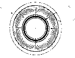
Shown in Fig. 6,7A and 7B, interior lamination 90 has many pure iron sheets 91 along arranged radially, and their plane is close to mutually.On each piece pure iron sheet 91, opening portion 90a is arranged all, and the inner end of pure iron sheet 91 welds together with weld seam 92, so that make these pure iron sheets 91 keep circular.At last, coil 95 is wound on the opening portion 90a of these pure iron sheets 91.Label 93 is the holes that are used to hold cylinder 60.
Shown in Fig. 8 A and 8B, in said structure, the end of lead 95a is connected with a side of coil 95, and its other end is connected with the power supply terminal (not shown), and lead 95a then is placed between interior lamination 90 and the magnetic gate plate 85.
Fig. 9 A and Fig. 9 B have illustrated another example, and wherein, lead 95a is connected with coil 95.As shown in the figure, the pure iron sheet 91 of the some of lamination 90 has cut away a part in forming, so that form the guide groove 99 with certain width and length.Above-mentioned lead 95a is connected with coil 95 by this guide groove 99.Wherein, lead 95a sweep might protrude from outside the guide groove 99.
But in the pattern in this coil is wound on the lamination, the heat that is produced in the welding process can pass to the pure iron sheet, and the transmission of this heat can make the pure iron sheet extend unevenly.Therefore, interior lamination and outside gap between the lamination will enlarge, thereby reduce the efficient of motor, also caused the error in the assembling process.
Also have, because in the coil on the lamination is placed in being wound between lamination and the magnetic gate plate, when the magnetic gate plate contacts with lead, will make harness damage when magnet is reciprocating.
Summary of the invention
Therefore, the purpose of this invention is to provide a kind of linear motor that solves the Linearkompressor of existing problem in the prior art.
An object of the present invention is to provide a kind of linear motor of Linearkompressor, it has been owing to simplified the assembling process of the pure iron sheet in the lamination, and can make its internal diameter and external diameter even, thereby has improved the efficient of motor.
Another object of the present invention provides a kind of linear motor of Linearkompressor, and it can prevent the damage of the lead of coil.
Specification hereinafter will further set forth other features and advantages of the present invention, a part wherein can be significantly draw from explanation, perhaps can recognize behind the present invention from implementing.According in the application's specification, claims and the accompanying drawing the special structure of describing just can understand objects and advantages of the present invention.
To achieve the object of the present invention, such as in the specification summary and describe in detail, the invention provides a kind of linear motor that sucks and discharge the Linearkompressor of extraneous gas with pressing mode, it has lamination in an outer lamination and, the coil that is connected with lead of reeling on the lamination in above-mentioned, and by the inside spin spring-loaded, it is characterized in that, above-mentioned linear motor also comprises: one group of lamination, wherein, on the concentric circles of the pure iron sheet of arranged radially, forming many ledges that have the joint filling groove respectively; Be used to a upper fixing element and a following fixture of preventing that above-mentioned pure iron sheet is loose in the above-mentioned joint filling groove with inserting.
Should be appreciated that above general description and the following detailed description all are give an example character and illustrative, are used for claimed the present invention is further explained.
Description of drawings
Below, embodiments of the present invention will be described in detail with reference to the accompanying drawings.In the accompanying drawing:
Fig. 1 is a kind of cross-sectional view of common Linearkompressor;
Fig. 2 is the stereogram of the coil of reeling in the above-mentioned common Linearkompressor;
Fig. 3 is the stereogram of part of the outer lamination of above-mentioned common Linearkompressor;
Fig. 4 is the plane graph of the combining structure of the coil of above-mentioned common Linearkompressor and outer lamination;
Fig. 5 is the schematic partial cross sectional of common linear motor, and one of them coil is wound on the outer lamination;
Fig. 6 is the stereogram of the interior lamination of common linear motor;
Fig. 7 A is the vertical cross section figure of the interior lamination among Fig. 6;
Fig. 7 B is the partial plan layout of the interior lamination of common linear motor;
Fig. 8 A is the cross-sectional view of the conductor arrangement example of common linear motor;
Fig. 8 B is the partial plan layout of the conductor arrangement among Fig. 8 A;
Fig. 9 A is the cross-sectional view of another example of conductor arrangement of common linear motor;
Fig. 9 B is the partial plan layout of the conductor arrangement among Fig. 9 A;
Figure 10 A is the vertical cross section figure according to the interior lamination of Linearkompressor of the present invention, and pure iron sheet wherein is all along arranged radially;
Figure 10 B is the plane graph of the interior lamination among Figure 10 A;
Figure 11 A is the vertical cross section figure according to the interior lamination of Linearkompressor of the present invention, wherein all fixes along the pure iron sheet of arranged radially;
Figure 11 B is the plane graph of the interior lamination among Figure 11 A;
Figure 12 is the cross-sectional view of a linear motor, and the retainer ring according to another kind of type of the present invention is described; And
Figure 13 is the cross-sectional view of a linear motor, and the layout according to lead of the present invention is described.
Preferred implementation
Represented the lamination device according to Linearkompressor of the present invention among Figure 10 A and Figure 10 B, lamination 100 wherein has many pure iron sheets along arranged radially.Figure 11 A and Figure 11 B represent lamination device of the present invention, and lamination 100 usefulness upper fixing elements 130 are wherein fixed.
Specifically, on the concentric circles of the pure iron sheet of arranged radially, forming ledge 120, and joint filling groove 120a is all being arranged on each ledge.
One with nonmagnetic substance or have the upper fixing element 130 that high-resistance material makes and insert among the joint filling groove 120a of each ledge 120.
In addition, as shown in figure 12, fixture in lamination 100 1 sides that supported by inside spin spring (not shown) can be made a following fixture 200, and the retainer ring 200a of this time fixture fixes above-mentioned lamination 100, and the supporting member 200b of ring-type is then supporting the inside spin spring.Said fixing ring 200a and annular support spare 200b make an integral body.Label 400 is cylinders.Therefore, above-mentioned upper fixing element 130 can be fixed the two ends of pure iron sheet 110, perhaps, above-mentioned upper fixing element 130 and following fixture 200 can be respectively the fixing two ends of pure iron sheet 110.
In Figure 13, form holddown groove 150 in a side of lamination 100, and a conductor 400 is fixed in the holddown groove 150 with preset width and degree of depth.Said fixing groove 150 forms by means of cut away a breach on the pure iron sheet 110 of predetermined quantity, so that the opening portion 100a around coil 300 can be linked to each other with a side of lamination 100, and above-mentioned conductor 400 has the terminal 400a of a pair of protrusion that is connected with external power source.In addition, above-mentioned conductor 400 also is connected with lead 310, and with making the epoxy molding of coil 300 insulation come out. Label 500 and 600 is outer lamination and magnetic gate plate, and this magnetic gate plate is reciprocating between two laminations 500 and 100.
The course of work about Linearkompressor with linear motor of the present invention has just no longer been described, because and of the prior art just the same.
As mentioned above, be according to the advantage of the linear motor of Linearkompressor of the present invention, It does not have the transmittance process of heat, because need to be for the heat treatment that adds of fixing pure iron sheet, And can also improve mass-produced productivity ratio, because in the assembling process of machinery, do not measure Error. In addition, because the width of each piece pure iron sheet all is uniformly, so last formation The internal diameter of lamination and external diameter all are uniformly, thereby have improved the efficient of motor and motor Reliability is because structure of the present invention has prevented lead in the motor operation process because lead Simple-arranged and damaged.
Clearly, in the art the technical staff can do not break away from principle of the present invention and Under the prerequisite of scope, the linear motor of Linearkompressor of the present invention is used for various modifications and becomes Type. Therefore protection scope of the present invention should be determined by claims.
Claims (6)
1. linear motor that sucks and discharge the Linearkompressor of extraneous gas with pressing mode, it has lamination in an outer lamination and, the coil that is connected with lead of reeling on the above-mentioned interior lamination, and by the inside spin spring-loaded, it is characterized in that it also comprises:
One group of lamination wherein, is forming many ledges that have the joint filling groove respectively on the concentric circles of the pure iron sheet of arranged radially; And
Insert and be used to the upper fixing element (130) and the following fixture (200) that prevent that above-mentioned pure iron sheet is loose in the above-mentioned joint filling groove.
2. linear motor as claimed in claim 1 is characterized in that, above-mentioned upper fixing element and following fixture are made by nonmagnetic substance.
3. linear motor as claimed in claim 1 is characterized in that, above-mentioned upper fixing element and following fixture are had high-resistance material and made by a kind of.
4. linear motor as claimed in claim 1, it is characterized in that, above-mentioned down fixture is in a side of above-mentioned lamination by the inside spin spring-loaded, this time fixture is made up of a retainer ring (200a) and a ring-shaped bearing piece (200b), said fixing ring (200a) embeds in the above-mentioned joint filling groove, fixing above-mentioned lamination, and above-mentioned ring-shaped bearing piece supports above-mentioned inside spin spring, and said fixing ring and above-mentioned ring-shaped bearing piece form an integral body.
5. linear motor as claimed in claim 1, it is characterized in that, formed the holddown groove of the preset width and the degree of depth above-mentioned by an end of the circumjacent lamination of coil, and had a conductor that is connected with lead to be fixed in the said fixing groove, above-mentioned lead is connected with above-mentioned coil.
6. linear motor as claimed in claim 5 is characterized in that, above-mentioned conductor and epoxy molding together, above-mentioned epoxy resin makes above-mentioned coil insulation.
Applications Claiming Priority (8)
| Application Number | Priority Date | Filing Date | Title |
|---|---|---|---|
| KR16050/97 | 1997-04-29 | ||
| KR1019970016050A KR100230781B1 (en) | 1997-04-29 | 1997-04-29 | Lamination fixing structure of linear motor |
| KR22554/97 | 1997-05-31 | ||
| KR22555/97 | 1997-05-31 | ||
| KR1019970022554A KR100259801B1 (en) | 1997-05-31 | 1997-05-31 | Structure for guiding lead wire of linear motor |
| KR1019970022555A KR100259802B1 (en) | 1997-05-31 | 1997-05-31 | Apparatus for guiding lead wire of linear motor |
| KR39679/97 | 1997-08-20 | ||
| KR1019970039679A KR100218481B1 (en) | 1997-08-20 | 1997-08-20 | Motor laminating fixing and spring supporter of a linear compressor |
Publications (2)
| Publication Number | Publication Date |
|---|---|
| CN1200592A CN1200592A (en) | 1998-12-02 |
| CN1098557C true CN1098557C (en) | 2003-01-08 |
Family
ID=27483200
Family Applications (1)
| Application Number | Title | Priority Date | Filing Date |
|---|---|---|---|
| CN98101736A Expired - Fee Related CN1098557C (en) | 1997-04-29 | 1998-04-27 | Linear motor structure for linear compressor |
Country Status (5)
| Country | Link |
|---|---|
| US (1) | US5945748A (en) |
| JP (1) | JP2935695B2 (en) |
| CN (1) | CN1098557C (en) |
| BR (2) | BR7803003Y1 (en) |
| DE (1) | DE19818883C2 (en) |
Families Citing this family (44)
| Publication number | Priority date | Publication date | Assignee | Title |
|---|---|---|---|---|
| KR100526006B1 (en) * | 1999-06-21 | 2005-11-08 | 피셔 앤 페이켈 어플라이언스 리미티드 | Linear motor |
| KR100425086B1 (en) * | 1999-09-02 | 2004-03-30 | 엘지전자 주식회사 | Mobile communication systemMobile and terminal and method for position tracking in terminal |
| DE19983919B3 (en) * | 1999-12-21 | 2012-04-05 | Lg Electronics Inc. | Piston support structure for a linear compressor |
| WO2001061830A1 (en) * | 2000-02-17 | 2001-08-23 | Lg Electronics Inc. | Structure for stator of reciprocating motor |
| KR100320217B1 (en) * | 2000-02-17 | 2002-01-10 | 구자홍 | Structure for preventing vibration of lamination sheet in stator of linear motor |
| BR0002187A (en) * | 2000-03-30 | 2001-11-13 | Brasil Compressores Sa | Process of forming an annular package of metal sheets of a linear motor stator and an annular opacity of formed metal sheets |
| SE521607C2 (en) * | 2000-04-07 | 2003-11-18 | Abb Ab | A linear electric machine |
| JP4734766B2 (en) * | 2000-07-18 | 2011-07-27 | Smc株式会社 | Magnet movable electromagnetic actuator |
| CN1284291C (en) * | 2000-09-26 | 2006-11-08 | 松下电器产业株式会社 | Linear gearing device |
| TW504546B (en) * | 2000-10-17 | 2002-10-01 | Fisher & Amp Paykel Ltd | A linear compressor |
| KR100386271B1 (en) * | 2001-02-02 | 2003-06-02 | 엘지전자 주식회사 | Structure for engaging lamination core of linear motor |
| DE10203709A1 (en) * | 2001-02-02 | 2002-10-02 | Lg Electronics Inc | Process for core lamination in an engine and its lamination construction |
| KR100430213B1 (en) * | 2001-04-07 | 2004-05-03 | 주식회사 엘지이아이 | Reciprocating motor |
| KR100390787B1 (en) * | 2001-04-19 | 2003-07-10 | 주식회사 엘지이아이 | Stator for reciprocating motor |
| KR100397557B1 (en) | 2001-04-19 | 2003-09-17 | 주식회사 엘지이아이 | Bobbin for reciprocating compressor and method for manufacturing the bobbin |
| BR0102566A (en) * | 2001-05-14 | 2003-02-25 | Brasil Compressores Sa | Linear motor and linear compressor including said motor |
| BR0102842A (en) * | 2001-05-22 | 2003-03-05 | Brasil Compressores Sa | Linear motor blade and blade arrangement |
| JP3636454B2 (en) * | 2001-05-24 | 2005-04-06 | エルジー エレクトロニクス インコーポレイティド | Reciprocating motor stator |
| KR100425841B1 (en) * | 2001-05-30 | 2004-04-03 | 주식회사 엘지이아이 | Apparatus for fixing stator reciprocating motor |
| KR100421388B1 (en) * | 2001-10-22 | 2004-03-09 | 엘지전자 주식회사 | Stator laminating structure and method in reciprocating motor |
| US6838789B2 (en) * | 2001-10-26 | 2005-01-04 | Lg Electronics Inc. | Reciprocating motor |
| NZ515578A (en) * | 2001-11-20 | 2004-03-26 | Fisher & Paykel Appliances Ltd | Reduction of power to free piston linear motor to reduce piston overshoot |
| BR0203507A (en) * | 2002-07-03 | 2004-05-25 | Brasil Compressores Sa | Linear motor stator, ring element pack and electric motor stator forming process |
| US6877214B2 (en) | 2002-11-05 | 2005-04-12 | L. H. Carbide Corporation | Method of manufacturing a stack of laminations |
| KR100518012B1 (en) * | 2003-03-11 | 2005-09-30 | 엘지전자 주식회사 | Structure of stator assembly for linear motor |
| JP3866209B2 (en) * | 2003-03-18 | 2007-01-10 | 日本電産サンキョー株式会社 | Linear actuator, pump device and compressor device using the same |
| NZ527999A (en) * | 2003-09-02 | 2005-08-26 | Fisher & Paykel Appliances Ltd | Controller improvements |
| CN1742420B (en) * | 2003-10-15 | 2012-02-08 | Lg电子株式会社 | Reciprocating motor |
| BR0304040A (en) * | 2003-10-23 | 2005-06-28 | Brasil Compressores Sa | Ring pack of blade elements |
| KR100548293B1 (en) * | 2003-12-30 | 2006-02-02 | 엘지전자 주식회사 | Structure for fixing magnet of reciprocating compressor |
| US7032400B2 (en) | 2004-03-29 | 2006-04-25 | Hussmann Corporation | Refrigeration unit having a linear compressor |
| KR100619731B1 (en) * | 2004-07-26 | 2006-09-08 | 엘지전자 주식회사 | Reciprocating motor and reciprocating compressor having the reciprocating motor |
| JP4614752B2 (en) * | 2004-12-08 | 2011-01-19 | 海二 佐藤 | Linear motor |
| KR100585682B1 (en) * | 2005-01-10 | 2006-06-07 | 엘지전자 주식회사 | Stator of reciprocating motor and menufacturing method thereof |
| KR100712919B1 (en) * | 2005-11-30 | 2007-05-02 | 엘지전자 주식회사 | Linear motor and linear compressor using the same |
| GB2436643A (en) * | 2006-03-31 | 2007-10-03 | Coverteam Ltd | Radial laminated stator for tubular electric machines |
| TWI383563B (en) * | 2008-11-28 | 2013-01-21 | Ind Tech Res Inst | A linear motor applied to compressor |
| US8390419B2 (en) * | 2010-12-21 | 2013-03-05 | General Electric Company | Electrical assembly and method for making the same |
| BRPI1103496A2 (en) | 2011-07-20 | 2013-10-01 | Whirlpool Sa | linear motor for compressor and compressor provided with linear motor |
| WO2014071854A1 (en) * | 2012-11-07 | 2014-05-15 | 海尔集团公司 | Stator of linear compressor and fixing method therefor, linear electric machine and linear compressor |
| CN103872805A (en) * | 2012-12-14 | 2014-06-18 | 海尔集团公司 | Inner stator piece, inner stator and compressor employing inner stator |
| CN105099010B (en) * | 2014-05-08 | 2018-12-18 | 青岛海尔智能技术研发有限公司 | A kind of stator structure and the Linearkompressor using the stator structure |
| KR102242373B1 (en) * | 2014-08-25 | 2021-04-20 | 엘지전자 주식회사 | A linear compressor |
| CN107040117B (en) * | 2016-02-04 | 2020-07-07 | 同济大学 | Stator of linear compressor, linear motor and linear compressor |
Citations (3)
| Publication number | Priority date | Publication date | Assignee | Title |
|---|---|---|---|---|
| CN1073307A (en) * | 1991-12-14 | 1993-06-16 | 冯建光 | Oscillating motor |
| US5440183A (en) * | 1991-07-12 | 1995-08-08 | Denne Developments, Ltd. | Electromagnetic apparatus for producing linear motion |
| CN1146533A (en) * | 1995-08-21 | 1997-04-02 | Lg电子株式会社 | Noise-reducing device for linear compressor |
Family Cites Families (5)
| Publication number | Priority date | Publication date | Assignee | Title |
|---|---|---|---|---|
| US5809638A (en) * | 1992-10-26 | 1998-09-22 | L.H. Carbide Corporation | Method for manufacturing laminated parts with center interlock |
| US5300845A (en) * | 1993-04-05 | 1994-04-05 | General Electric Company | Banded electromagnetic stator core |
| DE4432356A1 (en) * | 1994-09-12 | 1996-03-14 | Atlas Copco Elektrowerkzeuge | Assembly process for electric motor rotor shaft |
| EP0777826B1 (en) * | 1995-06-23 | 2001-11-21 | Lg Electronics Inc. | Oil supply apparatus for friction portion of linear compressor |
| US5715693A (en) * | 1996-07-19 | 1998-02-10 | Sunpower, Inc. | Refrigeration circuit having series evaporators and modulatable compressor |
-
1998
- 1998-04-17 US US09/062,447 patent/US5945748A/en not_active Expired - Lifetime
- 1998-04-23 BR BRMU7803003-0U patent/BR7803003Y1/en not_active IP Right Cessation
- 1998-04-23 BR BR9801434-0A patent/BR9801434A/en active IP Right Grant
- 1998-04-27 CN CN98101736A patent/CN1098557C/en not_active Expired - Fee Related
- 1998-04-28 DE DE19818883A patent/DE19818883C2/en not_active Expired - Fee Related
- 1998-04-28 JP JP10119009A patent/JP2935695B2/en not_active Expired - Fee Related
Patent Citations (3)
| Publication number | Priority date | Publication date | Assignee | Title |
|---|---|---|---|---|
| US5440183A (en) * | 1991-07-12 | 1995-08-08 | Denne Developments, Ltd. | Electromagnetic apparatus for producing linear motion |
| CN1073307A (en) * | 1991-12-14 | 1993-06-16 | 冯建光 | Oscillating motor |
| CN1146533A (en) * | 1995-08-21 | 1997-04-02 | Lg电子株式会社 | Noise-reducing device for linear compressor |
Also Published As
| Publication number | Publication date |
|---|---|
| JPH10323009A (en) | 1998-12-04 |
| DE19818883A1 (en) | 1999-02-18 |
| BR7803003Y1 (en) | 2014-04-15 |
| BR9801434A (en) | 1999-12-07 |
| CN1200592A (en) | 1998-12-02 |
| US5945748A (en) | 1999-08-31 |
| JP2935695B2 (en) | 1999-08-16 |
| DE19818883C2 (en) | 2002-12-12 |
Similar Documents
| Publication | Publication Date | Title |
|---|---|---|
| CN1098557C (en) | Linear motor structure for linear compressor | |
| CN1095235C (en) | Stator of linear compressor | |
| US6097125A (en) | Magnet fixed structure for compressor motor | |
| CN1284291C (en) | Linear gearing device | |
| CN1894529A (en) | Electromagnetic hydraulic valve, in particular 3/2-way selector valve for controlling a variable valve gear of an internal combustion engine | |
| CN1885679A (en) | Rotor of motor and manufacturing method thereof | |
| CN1574569A (en) | Outer stator for linear compressor motors | |
| CN1290244C (en) | Linear motor and linear compressor including said motor | |
| CN1237683C (en) | Stator for reciprocating motor and its manufacturing method | |
| US11349360B2 (en) | Motor | |
| CN101496258B (en) | Line start permanent magnet electric motor | |
| CN1573094A (en) | Linear compressor and method of producing the same | |
| CN1778030A (en) | Stepping motor being conveniently assembled and fabrication method of the same | |
| CN1106516C (en) | Piston support apparatus for linear compressor | |
| CN1149727C (en) | Stator structure of reciprocating electric machine | |
| CN1087514C (en) | Rotor of magnetic generator | |
| CN1208237A (en) | Ignition coil having toroidal magnet | |
| CN1699750A (en) | Linear motor and linear compressor having the same | |
| CN211606225U (en) | Flat wire stator structure | |
| EP2919366B1 (en) | Stator of linear compressor and fixing method therefor, linear electric machine and linear compressor | |
| KR100529902B1 (en) | Outer stator mounting structure of linear compressor | |
| CN114069894A (en) | Yoke and method of manufacturing the same | |
| KR19990062398A (en) | Stator of linear compressor | |
| KR100746415B1 (en) | Linear motor mounting for linear compressor | |
| CN1783365A (en) | Bistable two-way electromagnet |
Legal Events
| Date | Code | Title | Description |
|---|---|---|---|
| C10 | Entry into substantive examination | ||
| SE01 | Entry into force of request for substantive examination | ||
| C06 | Publication | ||
| PB01 | Publication | ||
| C14 | Grant of patent or utility model | ||
| GR01 | Patent grant | ||
| C17 | Cessation of patent right | ||
| CF01 | Termination of patent right due to non-payment of annual fee |
Granted publication date: 20030108 |