CN1120425C - Memory controller and memory control system - Google Patents
Memory controller and memory control system Download PDFInfo
- Publication number
- CN1120425C CN1120425C CN97102917A CN97102917A CN1120425C CN 1120425 C CN1120425 C CN 1120425C CN 97102917 A CN97102917 A CN 97102917A CN 97102917 A CN97102917 A CN 97102917A CN 1120425 C CN1120425 C CN 1120425C
- Authority
- CN
- China
- Prior art keywords
- instruction
- inlet
- memory
- synchronously
- mark
- Prior art date
- Legal status (The legal status is an assumption and is not a legal conclusion. Google has not performed a legal analysis and makes no representation as to the accuracy of the status listed.)
- Expired - Fee Related
Links
Images


Classifications
-
- G—PHYSICS
- G06—COMPUTING; CALCULATING OR COUNTING
- G06F—ELECTRIC DIGITAL DATA PROCESSING
- G06F15/00—Digital computers in general; Data processing equipment in general
- G06F15/16—Combinations of two or more digital computers each having at least an arithmetic unit, a program unit and a register, e.g. for a simultaneous processing of several programs
-
- G—PHYSICS
- G06—COMPUTING; CALCULATING OR COUNTING
- G06F—ELECTRIC DIGITAL DATA PROCESSING
- G06F13/00—Interconnection of, or transfer of information or other signals between, memories, input/output devices or central processing units
- G06F13/14—Handling requests for interconnection or transfer
- G06F13/16—Handling requests for interconnection or transfer for access to memory bus
- G06F13/1668—Details of memory controller
- G06F13/1689—Synchronisation and timing concerns
Abstract
A memory controller provided on a multiprocessor system has a scoreboard (11) used to manage the progress of memory access operations (the operating state of access instructions) and reduces the overhead in executing synchronization at a high level of execution priority. The scoreboard (11) holds synchronization flags set in response to the acceptance of synchronization as well as the operation codes and addresses of the accepted access instructions. The memory controller (10) sets a synchronization flag at the time when it has accepted a synchronizing instruction from the processor (1), and then resets the synchronization flag after the execution of the synchronizing operation has been completed.
Description
Technical field
The present invention relates to a kind of Memory Controller and memory control methods that is used for multicomputer system, specially refer to a kind of Memory Controller and memory control methods that makes the data sync of utilizing the storage of memory bank method.
Background technology
Multicomputer system has been provided with and has been used for management and control store body type (memory-bank-type) shared main storage and carries out the access instruction Memory Controller of (comprising data and address) with unordered (out-of-order) mode or weak order (weak-order) mode.
Memory Controller not only has the function that can control separately with corresponding each body memory in single memory zone, and, have the strong preface of temporary transient utilization and replace the synchronous function of weak order synchronously.The method relevant with this synchronous operation done following division approx.
First method is as follows: a memory buffer that has earlier-go out earlier (FIFO) function is used to address function, and carries out the access instruction that is sent by processor in proper order according to received address function.In this method, supposing the system has an address bus of isolating mutually with data bus.Here, address function means the operation of address bus.
Second method is as follows: have an admin table that is referred to as scoring plug.It is the process (running status of access instruction) of unit (memory bank unit) bookkeeping that this admin table is used to the independent range of control of storer.Utilize this method, in case synchronous operation is performed, so, refusal was not accepted address function before former operation was finished.That is, guarantee synchronous processing by trying synchronous operation again.
Since second method and first method reduced in comparison the read operation (reading accessing operation) carried out afterwards in write operation (storer writes accessing operation) stand-by period and increased the service efficiency of storer, so it has improved the overall performance of system in actual use.
But these methods have following problems.The memory buffer that first method has a FIFO function that is used for address function by use has guaranteed the execution of synchronous operation.But in this system, data manipulation (operation of data bus) is not always carried out according to the order of address function.Therefore, the imperfection of data manipulation will cause a kind of state, and under this state, the whole fifo buffer that is used for address function all will be used, and the state (examination again) of address function so just may occur refusing to accept.In addition, the shortcoming of first method is to work as and is used for can not carrying out follow-up read operation before the data transmission of preceding write operation is not finished, thereby has caused a large amount of stand-by period in the read operation process.
Second method is by using an admin table management operating state, and like this, it can be with no sequential mode or weak order mode execute store accessing operation.But,, thereby cause in the synchronous processing process, increasing the overhead of system in case this operation, then can not be carried out the follow-up operation operation of synchronous condition (or satisfy) by synchronously before preceding operation is finished.
Summary of the invention
One object of the present invention will provide a kind of Memory Controller and memory control methods exactly, and they can reduce described overhead in the memory reference instruction synchronizing process in multicomputer system.The present invention relates to the peculiar Memory Controller of multicomputer system, this system has an admin table, the process (running status of access instruction) that is used for the diode-capacitor storage accessing operation is so that reduce overhead in execution has the synchronous operation process of higher order precedence power.Admin table also maintains according to the set a plurality of sync marks of the reception of synchronous operation except a plurality of operational codes and address that keep the access instruction that receives.When from accessing operation of processor reception, Memory Controller is setting operation sign indicating number and address in admin table, and the reset synchronization mark.When Memory Controller received synchronous operation, it was provided with a sync mark.After synchronous operation was complete, it resetted this sync mark.Utilize this method, look to receive follow-up operation, this has been avoided such parts (unit), and these parts are asked described operation by trying a request again, thereby have reduced the overhead of system.
According to an aspect of the present invention, the invention provides a kind of Memory Controller, be used to respond the reception memorizer access instruction as unordered or weak order instruction and the strong preface instruction control storer of at least one synchronic command conduct, described Memory Controller comprises: the device of storage instruction admin table, described instruction admin table has a plurality of inlets of information of the executive process of the memory reference instruction that storage representation receives, each of described a plurality of inlets comprises at least one sync mark, and this sync mark shows whether the corresponding memory access instruction was received before synchronic command; And device, be used for according to the inlet information that comprises sync mark, after all memory reference instructions that received before the synchronic command are complete,, carry out the memory reference instruction that is received by carrying out the memory reference instruction that behind synchronic command, receives.
According to a further aspect in the invention, the present invention also provides a kind of memory control methods that uses in having the computer system of Memory Controller, be used to respond the reception memorizer access instruction as unordered or weak order instruction and the strong preface instruction control storer of at least one synchronic command conduct, described Memory Controller comprises the device of storage instruction admin table, this instruction admin table has a plurality of inlets of information of the executive process of the memory reference instruction that storage representation receives, described method comprises following step: each that makes described a plurality of inlets comprises at least one sync mark, and this sync mark shows whether the corresponding memory access instruction was received before synchronic command; And, after all memory reference instructions that received before the synchronic command are complete,, carry out the memory reference instruction that is received by carrying out the memory reference instruction that behind synchronic command, receives according to the inlet information that comprises sync mark.
In addition, the present invention also is applied on the memory controller, and this Memory Controller is used to control the storer such as a plurality of independent controllable memory of having of memory bank system zone.Be provided with an admin table that is used for each memory area (each body memory), this has expressed each operation state of a process, but and maintains the executive condition that is used for each operation.In addition, this admin table also maintains and all is used for being identified in the mark of carrying out the operation of carrying out before this synchronous operation according to these performed operations after carrying out synchronous operation.This admin table makes can carry out an inspection, whether finish with the operation of having a look at before carrying out synchronous operation, and, even under the situation that synchronous operation is not also finished, also can receive follow-up operation, whereby to avoid asking the parts of an operation by trying a request again.When before current synchronous operation is done, producing a subsequent operation, rejection is used for the subsequent synchronisation request of operating, request will be tried again then.
Additional purpose of the present invention and advantage will embody in the following description, and a part wherein will be clearly in this description, and remaining can be learnt in practice.Objects and advantages of the present invention can be by means of the means of pointing out in claims with in conjunction with realizing and obtaining.
Description of drawings
Insert and constitute the accompanying drawing of this instructions part and the general description that provides above shows the current most preferred embodiment of the present invention together, the detailed description of most preferred embodiment will provide below, be used to explain principle of the present invention.
The block scheme of Fig. 1 shows according to a computer system of the present invention;
Fig. 2 is a conceptual view, is used to explain the structure according to the scoring plug of first embodiment of the invention;
The block scheme of Fig. 3 shows the Memory Controller of first embodiment of the invention;
The process flow diagram of Fig. 4 is used to explain the operation of first embodiment;
Fig. 5 A is used for explaining operation at first embodiment Memory Controller when having received a memory reference instruction to the process flow diagram of 5B;
The process flow diagram of Fig. 6 is used to explain that the memory bank performance element place with at first embodiment sends a definite processing that instruction is relevant;
Fig. 7 A shows in first embodiment two scoring plug and finishes the example of table synchronously to 7C;
Fig. 8 A shows in first embodiment two scoring plug and finishes the example of table synchronously to 8C;
Fig. 9 A shows in first embodiment two scoring plug and finishes the example of table synchronously to 9C;
Figure 10 A shows in first embodiment two scoring plug and finishes the example of table synchronously to 10C;
Figure 11 A shows in first embodiment two scoring plug and finishes the example of table synchronously to 11C;
Figure 12 A shows in first embodiment two scoring plug and finishes the example of table synchronously to 12C;
Figure 13 A shows in first embodiment two scoring plug and finishes the example of table synchronously to 13C;
Figure 14 A shows in first embodiment two scoring plug and finishes the example of table synchronously to 14C;
Figure 15 A shows in first embodiment two scoring plug and finishes the example of table synchronously to 15C;
Figure 16 A shows in first embodiment two scoring plug and finishes the example of table synchronously to 16C;
The conceptual view of Figure 17 is used to explain the structure according to a scoring plug of second embodiment of the invention;
The process flow diagram of Figure 18 is used for determining in a second embodiment and is carrying out the relevant processing of instruction that place, memory bank unit sends;
Figure 19 A and 19B show scoring plug in a second embodiment and finish the example of table synchronously;
Figure 20 A and 20B show scoring plug in a second embodiment and finish the example of table synchronously;
Figure 21 A and 21B show scoring plug in a second embodiment and finish the example of table synchronously;
Figure 22 A and 22B show scoring plug in a second embodiment and finish the example of table synchronously;
Figure 23 A and 23B show scoring plug in a second embodiment and finish the example of table synchronously;
The conceptual view of Figure 24 is used to explain the structure according to the scoring plug of third embodiment of the invention;
The process flow diagram of Figure 25 shows the operation of Memory Controller when receiving a memory reference instruction in the 3rd embodiment;
The process flow diagram of Figure 26 shows the relevant definite processing of instruction of sending with place, execution memory bank unit at the 3rd embodiment;
Figure 27 A and 27B show in the 3rd embodiment score sheet and finish the example of table synchronously;
Figure 28 A and 28B show in the 3rd embodiment score sheet and finish the example of table synchronously;
Figure 29 A and 29B show in the 3rd embodiment score sheet and finish the example of table synchronously;
Figure 30 A and 30B show in the 3rd embodiment score sheet and finish the example of table synchronously;
Figure 31 A and 31B show in the 3rd embodiment score sheet and finish the example of table synchronously;
Figure 32 A and 32B show in the 3rd embodiment score sheet and finish the example of table synchronously;
Figure 33 A and 33B show in the 3rd embodiment score sheet and finish the example of table synchronously;
The conceptual view of Figure 34 is used to explain the structure according to a scoring plug of fourth embodiment of the invention;
The process flow diagram of Figure 35 shows the relevant definite processing of instruction of sending with place, execution memory bank unit at the 4th embodiment;
Figure 36 A and 36B show in the 4th embodiment scoring plug and finish the example of table synchronously;
Figure 37 A and 37B show in the 4th embodiment scoring plug and finish the example of table synchronously;
Figure 38 A and 38B show in the 4th embodiment scoring plug and finish the example of table synchronously;
Figure 39 A and 39B show in the 4th embodiment scoring plug and finish the example of table synchronously;
Figure 40 A and 40B show in the 4th embodiment scoring plug and finish the example of table synchronously;
Figure 41 A and 41B show in the 4th embodiment scoring plug and finish the example of table synchronously;
Figure 42 A and 42B show in the 4th embodiment scoring plug and finish the example of table synchronously;
The conceptual view of Figure 43 is used to explain the structure according to a scoring plug of fifth embodiment of the invention;
The process flow diagram of Figure 44 shows the operation of Memory Controller when receiving memory reference instruction in the 5th embodiment;
The process flow diagram of Figure 45 shows the definite processing that instruction is relevant of sending with place, execution memory bank unit at the 5th embodiment;
Figure 46 shows in the 5th embodiment scoring plug and finishes the example of table synchronously;
Figure 47 shows in the 5th embodiment scoring plug and finishes the example of table synchronously;
Figure 48 shows in the 5th embodiment scoring plug and finishes the example of table synchronously;
Figure 49 shows in the 5th embodiment scoring plug and finishes the example of table synchronously;
Figure 50 shows in the 5th embodiment scoring plug and finishes the example of table synchronously;
Figure 51 shows in the 5th embodiment scoring plug and finishes the example of table synchronously;
Figure 52 shows in the 5th embodiment scoring plug and finishes the example of table synchronously;
Figure 53 shows in the 5th embodiment scoring plug and finishes the example of table synchronously;
The conceptual view of Figure 54 is used to explain the structure according to a scoring plug of sixth embodiment of the invention;
The conceptual view of Figure 55 is used to explain the structure according to a scoring plug of seventh embodiment of the invention;
The conceptual view of Figure 56 is used to explain the structure according to a scoring plug of eighth embodiment of the invention;
The conceptual view of Figure 57 is used to explain the structure according to a scoring plug of ninth embodiment of the invention; With
The conceptual view of Figure 58 is used to explain the structure according to a scoring plug of tenth embodiment of the invention.
Embodiment
With reference to the accompanying drawings embodiments of the invention are made an explanation.The block scheme of Fig. 1 shows according to a computer system of the present invention.The conceptual view of Fig. 2 is used to explain the structure with the corresponding to scoring plug of first embodiment of the invention.The block scheme of Fig. 3 shows the Memory Controller of first embodiment.The process flow diagram of Fig. 4 is used to explain the operation of first embodiment.
(system architecture)
As shown in the figure, system of the present invention is a multicomputer system with a plurality of processors, has one as shared main storage and storer with the bank structure that is made of to BM3 a plurality of body memory BM0.
Each processor 1 all passes through the Bus Interface Unit 3 that is connected to processor bus 2 and sends an access instruction to Memory Controller 10.In processor bus 2, data bus 2A and address bus 2B isolate mutually.What be connected to processor bus 2 is an I/O controller 4, and this I/O controller 4 is connected on the I/O device such as hard disk unit (HDD) 5 and LAN interface 6.
When receiving the memory reference instruction of a from processor 1, Bus Interface Unit 3 is transferred to Memory Controller 10 with this instruction.Memory Controller 10 has one to be used for managing with body memory BM0 and to finish table 12 synchronously to 11 and one of the scoring plug (admin table) of each relevant corresponding accessing operation of access instruction of BM3.Memory Controller has 4-path (way) interleaving function, be used to control as at the body memory BM0 in range of control internal storage zone separately to BM3.
(structure of scoring plug)
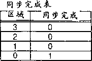
Scoring plug 11 is tables, and it not only shows operation state of a process (running status of access instruction), but and shows and the relevant executive condition of each operation.Scoring plug 11 has the mark that all is used for being identified in according to these performed operations after carrying out synchronous operation the operation of carrying out before this synchronous operation of execution.Finishing table 12 synchronously is tables, (SYNC finishes), and whether the synchronous operation that it shows in each storage area of 0 to 3 is finished.
The scoring plug 11 of current embodiment is by forming with 4 isolated memory area territories, 0 to 3 corresponding scoring plug 100,110,120 and 130.Each scoring plug all has into slogan (No) 102, operational code 103, address 104, be used to represent to operate finishing mark 105, be used to represent to operate the mark 106 that can begin, be used for expression effective significant notation 107 of inlet and sync mark (SYNC mark) 101 of finishing.
Go into slogan 102 and be used to be identified in the interior a plurality of inlets of scoring plug.Operational code 103 is inlets, is used to keep 1 requested operation type of processor (for example, " reading " to mean that read operation and " writing " mean write operation).Address 104 is inlets, be used to keep will be accessed storage address.Finishing mark 105 sending of expression operation finishes.In significant notation, when corresponding inlet is effective, mark V (effectively) is set, when corresponding inlet is invalid, mark I (invalid) is set.In other words, will be issued with the corresponding inlet of mark V, and with the corresponding inlet of mark I be the sky inlet that is not issued.
The body performance element (by the label in storage area 0 108 expression) that is provided for each scoring plug not only produces the entry address selected according to relevant scoring plug and DRAM (dynamic ram) address that is made of the body memory and the Memory Controller signal that comprise such as RAS and CAS but also carry out and comprise the processing of sending inlet (will be described below).The body performance element 108,118,128 and 138 that provides on scoring plug 100,110,120 and 130 respectively is connected to describedly to be finished on the table synchronously.
Sync mark (SYNC mark) is set up (resetting) usually and becomes " 0 ".Finish in the table 12 synchronously, finish mark (SYNC finishes) synchronously and be provided in the single memory area 0 to 3 each, and be configured to " 0 " usually, it means synchronously finishes.
When from processor 1, receiving a synchronous operation, Memory Controller 10 is set to " 1 " with all sync marks that effectively inlet is relevant that enter in scoring plug 100,110,120 and 130, all the other sync marks relevant with invalid inlet are set to " 0 ".At this time point place, be set to " 1 " finishing the mark of finishing synchronously relevant in the table 12 synchronously with memory area with invalid inlet, simultaneously, relevant with the memory area with invalid inlet (that is: do not operate in etc. the pending) mark of finishing synchronously is maintained at and is " 0 ".
When receive one be different from synchronous operation subsequent operation the time, the sync mark in scoring plug is set to " 0 ", whereby, to discern the operation that is received according to a operation before synchronous operation.Last operation that is set to " 1 " when its sync mark is set to " 0 " at the mark of finishing in the table 12 synchronously of finishing synchronously when disappearing from corresponding memory block.As long as finish mark synchronously and be in one state finishing at least one that be used for each memory area in the table 12 synchronously, the operation that scoring plug just only allows sync mark to be in one state is performed.
(first embodiment)
Below, with reference to the operation of Fig. 3 to the concise and to the point description of Fig. 4 first embodiment.
As mentioned above, the Memory Controller 10 of this embodiment by the control of 4-path interleaving function and 4 memory area 0 to 3 corresponding body memory BM0 to BM3.Memory Controller 10 as shown in Figure 3 comprises performance element 108,118,128,138 and scoring plug 100,110,120,130, and they are offered 4 body memory BM0 respectively separately to BM3.In scoring plug 100,110,120,130, significant notation sends enable flag by " Fn " expression by " Val " expression, and sync mark is represented by " SYNC ".
As shown in Figure 4, after having received a memory reference instruction from processor bus 2, Bus Interface Unit 3 is transferred to Memory Controller 10 (step S1) with this instruction.When receive one to memory area 0 in 3 during one memory reference instruction, Memory Controller 10 is inlet porting (step S2) in relevant scoring plug.
As shown in Figure 3, in this embodiment, storage address is that unit is divided into body memory BM0 to BM3 with 4 bytes.Particularly, memory area is that unit is assigned to body memory BM0 to BM3 with 4 bytes, and from 4 bytes on each address LSB one side (0,4,8, C).For simplicity, the inlet number that can import in each scoring plug is assumed to be 4.
Fig. 3 shows a kind of situation, in this case, utilization is in two effectively inlet reception synchronous operations (a significant notation Val is configured to the inlet of " V ") that are used for memory bank BM0 of scoring plug 100, an effective inlet on scoring plug 110 is used for memory bank BM1, effectively do not enter the mouth on scoring plug 120 and be used to memory bank BM2, ineffective inlet is used to BM3 on scoring plug 130.Particularly, in scoring plug 100 and 110, the sync mark (SYNC) that its significant notation Val is set to " V " changes to " 1 " from " 0 ", and its significance bit Val is that the inlet of " I " remains " 0 " (keeping changing).
At the same time, for with at each memory area 0 to 3 corresponding mark (SYNC finishes) of finishing synchronously of finishing synchronously in the table 12, change to " 1 " with memory area 0 with effective inlet (memory bank BM0) and the corresponding value of memory area 1 (memory bank BM1) from " 0 ", simultaneously, remain unchanged in " 0 " with memory area 2 that does not have effective inlet (memory bank BM2) and the corresponding value of memory area 3 (memory bank BM3).
In addition, in scoring plug 100,110, be used for going into slogan No 1 and going into slogan No 0 place of memory bank BM0, sending enable flag En and be enabled and maybe can be performed, thereby allow the operation (read operation) on appropriate address to be performed (step S6 and S7) what be used for memory bank BM1.
After the accessing operation of all performance element E0, E1 was done, controller 10 reset to " No " or " 0 " (step S8 and S9) with enable flag En and sync mark.At this moment and since the inlet that sync mark is configured to " 1 " with the corresponding scoring plug 110 of memory bank BM1 on do not occur, so, finish mark and also be reset to " 0 " finishing in the table 12 corresponding synchronous synchronously.
When asking follow-up memory access operation, the sync mark for " 0 " is transfused to described scoring plug, to be used for and the corresponding memory area of access instruction.Promptly be configured to a new subsequent operation of synchronous operation identification of " 1 " according to its sync mark before synchronous operation.In addition, when request under state shown in Figure 3 during second synchronous operation since have one its finish synchronously and be marked at that to finish in the table 12 synchronously be not the inlet (memory area 0 of " 0 ", 1), so second synchronous operation will be rejected and described synchronous operation is tried again.If all sync marks all are configured to " 0 ", this just means that synchronous operation finishes.Therefore, in this case, finishing table 12 synchronously can be omitted.
Below, will explain the operation of first embodiment of the invention in detail.
At first, explain processing under the situation that in first embodiment memory reference instruction sent by CPU1 with reference to Fig. 5.
The memory reference instruction of being sent by CPU1 is sent to Bus Interface Unit 3 through bus 2.Bus Interface Unit 3 sends the memory reference instruction that is received to Memory Controller 10 (step S11).
When the memory reference instruction that is received was a memory reference instruction except that synchronic command, Memory Controller 10 was selected a corresponding scoring plug according to the address of the memory reference instruction that is received from scoring plug 100,110,120 and 130.In addition, Memory Controller 110 selects its significant notation to be set to the inlet (inlet of a sky) of " I " from all inlets on selected scoring plug.Then, Memory Controller 10 inputs to selected inlet (step S12) with the memory reference instruction that is transmitted.
When the input store access instruction, Memory Controller 10 is the operational code and the address of input store access instruction not only, and the significant notation that will be used to import the inlet of this instruction is arranged to " V " and sync mark reset to " 0 ".
When from synchronic command of Bus Interface Unit 3 receptions, the significant notation that Memory Controller 10 will be imported in selected scoring plug is configured to the sync mark of all inlets of " V " and is arranged to " 1 "
In addition, under the control of body performance element 108,118,128 and 38, Memory Controller 10 is selected an inlet and send instruction in this inlet from scoring plug.
(step S13, in the time of YES), the enable flag that is used for selected inlet is configured to " NO " (step S14) when and instruction this porch selected at the inlet (memory reference instruction) of step S12 input are issued.That utilizes Bus Interface Unit 3, Memory Controller 10 and body performance element to carry out to be sent deposits the gauge access instruction,
After the processing of memory reference instruction is done, Memory Controller 10 will be stored in the significant notation that is used for the inlet of execute store access instruction on the described scoring plug and be arranged to " I ", and " 0 " (step S15) is arranged in sync mark.Handle by means of these, wherein imported the inlet that is performed memory reference instruction and be configured to freely.
By above-mentioned processing, carry out the memory reference instruction that transmits by CPU1.
Below, each place that is described in body performance element 108,118,128 and 138 with reference to accompanying drawing 6 sends the processing that corresponding scoring plug 100,110,120 and 130 are given in instruction.
An inlet that will send described memory reference instruction has been imported in consideration on scoring plug, whether the significant notation that the body performance element at first is identified for relevant inlet is configured to " I " (step S21).When the significant notation that is used for relevant inlet is configured to " I ", because described relevant inlet is invalid, so the body performance element is determined: the memory reference instruction in this relevant inlet can not be issued (step S22).
(step S21, in the time of NO), whether the enable flag that the body performance element is identified for this relevant inlet is in " NO " state (step S23) if the significant notation of inlet is in " V " state when being used for relevant.When being used for this relevant enable flag that enters the mouth is when being in " NO " state, and the body performance element determines that it still is not have to send memory reference instruction (step S24) in this relevant inlet owing to not satisfying the condition of sending that the instruction in relevant inlet has been issued.
(step S23, NO), the body performance element is determined whether " SYNC COMPLETION " has and is used for finishing a plurality of " 0 " (the step S25) of table 12 All Ranges synchronously when the enable flag that is used for relevant inlet is in " YES ".Do not mean and send synchronic command because " SYNC COMPLETION " has the state of a plurality of " 0 " that are used for All Ranges, so the body performance element determines that the memory reference instruction in relevant inlet can be issued (step S26) from CPU1.
Has " 1 " (step S25 who is used for finishing synchronously any one zone in a plurality of zones of table when item " SYNC COMPLETION ", No) time, whether the sync mark that the body performance element is identified for described relevant inlet is in " 0 " state (step S27).When the sync mark that is used for this relevant inlet is when being in " 0 " state, because instruction in relevant inlet is a memory reference instruction of importing on scoring plug after Memory Controller 10 has received a synchronic command, so the body performance element can not send memory reference instruction (step S28).
When sync mark is in one state (step 27 NO), because the memory reference instruction in this relevant inlet is the memory reference instruction of input before synchronic command is transmitted, so the body performance element determines that the memory reference instruction in this relevant inlet can be issued (step S29).Carried out above-mentioned definite processing on all inlets of scoring plug after, the body performance element sends the inlet processing of sending of selecting an inlet and carrying out relevant inlet from one or more.
Explained later is the processing of Memory Controller 10 in first embodiment when CPU1 transmits following instruction with ascending order:
(1) writes 12380
(2) read 246824
(3) read 67830
(4)SYNC
(5) read abc70
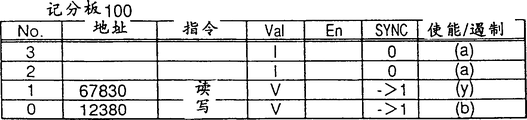
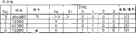
Fig. 7 A shows in scoring plug 110 data item that is used for zone 1 of input to 16C, the data item of importing scoring plug 100 in that is used for area 0 and finish table 12 synchronously.
In 16C, the instruction " ISSUE ENABLE/DISABLE " that is included in each inlet keeps being illustrated in the information that body performance element among Fig. 6 is determined the result at interior item, and is as follows: (a) corresponding to the definite result of Fig. 6 at step S22 place at Fig. 7 A; (b) corresponding to definite result at step S24 place; (x) corresponding to definite result at step S26 place; (c) corresponding to definite result at step S28 place; (y) corresponding to definite result at step S29 place.This makes understands functional unit easily.But in fact described item not only keeps " ISSUE ENABLE/DISABLE " information of an instruction pointing out just now.
Fig. 7 A shows scoring plug 100,110 and finishes the virgin state of table 12 synchronously to 7C.Therefore, the inlet of all in scoring plug 100 and 110 all is not used (sky).In all inlets on scoring plug 100 and 110 under " ISSUE ENABLE/DISABLE ", the data of expression ISSUE DISABLE have been imported.This is corresponding to (a), and it means that a plurality of inlets are invalid when the operation of body performance element 108 and 118 execution graphs 6.Subsequently, there is not the input that to send yet.
Fig. 8 A shows to 8C and is transmitting the scoring plug 100,110 under the situation of instruction (1) " Write 12380 " from Bus Interface Unit 3 and finishing table 12 synchronously.Memory Controller 10 from the corresponding scoring plug 100 of area 0 select empty inlet No.0.Area 0 is assigned to a presumptive address, and this address comprises the address by instruction " Write 12380 " appointment.Memory Controller 10 inputs to a selecteed inlet with this instruction.Scoring plug 110 does not have the input that can send, and simultaneously, the inlet No.0 on scoring plug 100 can be issued.
After this Fig. 9 A shows to 9C and has received the scoring plug 100,110 under the situation of instruction (2) " Read 246824 " and finished table 12 synchronously at Memory Controller 10.Memory Controller 10 is the empty inlet of corresponding regional 1 scoring plug 110 selections No.0 from the address that is used for and instruction " Read 246824 ", and this instruction of input in this inlet.Inlet No.0 on each can be issued in scoring plug 100 and 110.
After this Figure 10 A shows to 10C and has received the scoring plug 100,110 under the situation of instruction (3) " Read 67830 " and finished table 12 synchronously at Memory Controller 10.Memory Controller 10 is selected empty inlet No.1 and this instruction is inputed to this inlet from the scoring plug 100 of the corresponding area 0 in address that is used for and instruction " Read 67830 ".Can be issued at the inlet No.0 on the scoring plug 100 and inlet No.1 and the inlet No.0 on scoring plug 110.
Figure 11 A shows body performance element 108 to 11C and selects inlet No.0 the inlet and send the scoring plug 100,110 under this input condition and finish table 12 synchronously from sending on scoring plug 100.Among the inlet No.0 on scoring plug 100 under " ISSUE ENABLE/DISABLE ", the information of input expression " ISSUE DISABLE ".This is corresponding to (b), and it means that instruction is issued.Inlet No.0 in scoring plug 100 and 110 on each can be issued.
Figure 12 A and 12C show at Memory Controller 10 and have received the scoring plug 100,110 under synchronic command (4) " SYNC " situation and finish table 12 synchronously from Bus Interface Unit 3.Among the inlet No.0 of the inlet No.0 under item " SYNC " on the scoring plug 100 and inlet No.1 and scoring plug 110, one " 1 " is set.Among the inlet No.0 and the inlet No.0 on scoring plug 110 under item " ISSUE ENABLE/DISABLE " on the scoring plug 100, the information of input expression " ISSUE ENABLE ".This is corresponding to (y), it mean described instruction be an input before the synchronic command input instruction.With in the area 0 and zone 1 corresponding inlet finished synchronously in the table 12, one " 1 " is set also.
Figure 13 A shows at Memory Controller 10 to 13C and has received the scoring plug 100,110 under instruction (5) " Read abcd70 " situation and finished table 12 synchronously.Memory Controller 10 is selected empty inlet No.2 and import this instruction in this inlet from the scoring plug 100 in the corresponding zone, address that is used for and instruction " Read abcd70 ".Only the inlet No.1 on scoring plug 100 can be issued.
Figure 14 A shows at body performance element 108 to 14C and has selected at the sent inlet No.1 on the scoring plug 100 and send this input signal and body performance element 118 has been selected at the inlet No.0 on the scoring plug 110 and sent the scoring plug 100,110 under this input signal situation and finish table 12 synchronously.In each input of sending under item " En ", " YES " is changed " NO ".
Figure 15 A shows the scoring plug 100,110 under being done situation in the instruction in inlet No.1 on the scoring plug 100 and finishes table 12 synchronously to 15C.Among inlet No.0 on scoring plug 100 under " Val " and the inlet No.1, " V " become " I ", and under item " SYNC ", these inlets are reset to " 0 ".Be reset to " 0 " at the corresponding inlet of finishing in the table 12 synchronously of area 0
Figure 16 A to 16C show instruction at scoring plug 110 upper inlet No.0 be done under the situation scoring plug 100,110 and finish table 12 synchronously.Among the inlet No.0 on scoring plug 110 under the Val, " V " become " I ", and under item " SYNC ", this inlet is reset to " 0 ".Zone 1 corresponding inlet is reset to " 0 " in the table 12 with finishing synchronously.
Above-mentioned processing make Memory Controller 10 can avoid such as the inlet No.1 on the scoring plug 100 (instruction (3)) before or receive scoring plug 110 upper inlet No.0 (instruction (2)) that synchronic command (4) " SYNC " import before carry out before the processing of startup synchronic command of inlet No.29 (instruction (5)) of input in scoring plug 100 selected with send.
(second embodiment)
As shown in figure 17, the second embodiment of the present invention is to finish synchronously and has added the inlet 160 that is used for synchronous condition in the table 12.Inlet 160 is items, be used for expression with from relevant synchronous condition of same requestor's (processor) request or the synchronous condition (here, assumed conditions is used to same address) of being correlated with same address.Memory Controller 10 remaining system architecture are identical with first embodiment with formation.
The function that said structure has realized carrying out the continual command (continued operation) that does not satisfy synchronous condition can't be subjected to the influence of synchronous operation.In the operation of satisfying synchronous condition, forbid that the operation of carrying out is performed early than the operation of carrying out after synchronous operation before synchronous operation.In the operation of not satisfying synchronous condition, carry out general operation (unordered processing or weak order are handled).When having before finishing synchronously a subsequent synchronisation operation to be requested, this follow-up synchronous operation of rejection and this synchronous operation being tried again described.
Below, 17 second embodiment are described briefly in conjunction with the accompanying drawings.
Second embodiment is characterised in that finishing synchronously and has added a synchronous condition inlet 160 in the table 12.In inlet 160, be provided with synchronous condition.For example, synchronous condition can be " until all of the write operations have been completed) (till all write operations all are done) or " until all of the read and write operation have been completed " (and up to all read all be done with write operation till).
In a second embodiment, regulation does not guarantee to be written into same address according to data and the order of reading from same address is carried out operation (discontinuous operation) and the system that guarantees the operation (continued operation) of execution in order, supposed in synchronous condition, the synchronous operation under promptly " before being done with read operation, forbidding follow-up writing and read operation " at writing of same address.
Under the state of Figure 17, because scoring plug 100 and the scoring plug in memory area 1 110 in memory area 0 have effective inlet, so, be configured to " 1 " at the mark of finishing in the table 12 synchronously of finishing synchronously.In addition, because scoring plug 120 and the scoring plug in memory area 3 130 in memory area 2 do not have effective inlet, so the relevant mark of finishing synchronously remains " 0 ".
Sync mark in effectively entering the mouth in memory area 0 and 1 is configured to " 1 ", and the sync mark in invalid inlet remains " 0 ".At the same time, in the inlet 160 relevant, import following synchronous condition with finishing synchronous condition in the table 12 synchronously, that is: " forbid follow-up reading and write operation before being done with write operation reading " at all of same address.
Under this synchronous condition, when the inlet that is set to " 1 " when its sync mark has identical address, do not send follow-up read operation, and when this inlet does not have identical address, send follow-up read operation.In this case, be done and its sync mark is in ' 1 " after the inlet of state do not occurring; in case the condition of sending is satisfied; just can be emitted in the input signal of having imported on the scoring plug and will having imported, and needn't consider whether the synchronous operation on another scoring plug is finished in synchronous operation with the corresponding scoring plug in described address.That is: in this case, can execute store visit under condition identical when being not synchronous operation.
When utilizing first embodiment, when finishing in the table 12 at least one synchronously and finish mark synchronously and be in one state (during synchronous processing), will reject second synchronous operation and try this synchronous operation again.When all sync mark many places during, this means that all synchronous operation all is done in " 0 " state.Therefore can omit and finish table 12 synchronously.
Below, be further explained in detail the operation of second embodiment.
In a second embodiment, sent at CPU under the situation of memory reference instruction, it is handled with similar in the processing of first embodiment shown in Figure 17, and therefore, the detailed explanation of second embodiment is omitted.
Below, each place that is described in the body performance element 108,118,128 that provided and 138 with reference to Figure 18 sends the processing of instruction respectively to scoring plug 100,110,120 and 130.
Consider the inlet of wherein having imported the memory reference instruction that will be issued on scoring plug, whether the significant notation that the body performance element at first is identified for relevant inlet is in " I " state (step S31).When the significant notation that is used for relevant inlet was in " I " state, the body performance element was determined: because relevant inlet is invalid, so the memory reference instruction in relevant inlet can not be issued (step S32).
When the significant notation that is used for relevant inlet was in " V " state (step S31 NO), the body performance element was identified for sending of relevant inlet and marks whether to be in " NO " state (step S33).When being used for the sending mark and be in " NO " state of relevant inlet, the body performance element determines to have sent the instruction in relevant inlet, and is not emitted in the memory reference instruction (step S34) in the relevant inlet.
When the mark that sends that is used for relevant inlet is in " YES " state (step S33, in the time of NO), the body performance element is determined whether " SYNC COMPLETION " has and is used for finishing a plurality of " 0 " (the step S35) of table 12 All Ranges synchronously.Because having the state of a plurality of " 0 " that are used for All Ranges, " SYNC COMPLETION " do not mean, so the body performance element determines that the memory reference instruction in relevant inlet can be issued (step S36) from CPU1 transmission synchronic command.
When item " SYNC COMPLETION " only have one be used for finish any one zone of table 12 synchronously 1 (step S35, in the time of NO), the body performance element determines whether this inlet satisfies synchronous condition (step S37).When this inlet did not satisfy in the synchronous condition of finishing synchronously in the table 12, the body performance element determined that it is unwanted that synchronic command is handled, and the memory reference instruction in relevant inlet can be performed (step S38).
(step S37, in the time of YES), whether the sync mark that the body performance element is identified for relevant inlet is in " 0 " state (step S39) when this inlet satisfies synchronous condition.When the sync mark that is used for relevant inlet is in " 0 " state, because the instruction in relevant inlet is to have received the memory reference instruction of importing after the synchronic command at Memory Controller 10 in scoring plug, so the body performance element can not send memory reference instruction (step S40).
When described sync mark is in one state (step S39, NO) time, because the memory reference instruction of input is a memory reference instruction of input before synchronic command is transmitted in relevant inlet, so the body performance element determines that the memory reference instruction in relevant inlet can be performed (step S41).
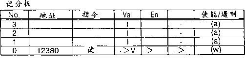
The explained later operation of Memory Controller 10 when CPU1 transmits following instruction with ascending order in a second embodiment:
(1)Read 12380
(2)SYNC
(3)Write?67830
(4)Write?12380
Figure 19 A shows the data item of input in the scoring plug 100 that offers area 0 and finishes table 12 synchronously to 23B.
Here, suppose " all at same address read and write forbid follow-up reading and writing before being done " condition be confirmed as synchronous condition.This means when SYNC instruction in subsequent operation (sync mark for " 0 ") (sync mark is " 1 ") during synchronic command is handled has instruction at same address before, instruction can not be issued, simultaneously, when such instruction did not exist, described instruction can be issued.
In 23B, comprise that the item that is illustrated in the instruction " ISSUE ENABLE/DISABLE " in each inlet remains on the information of the following definite result of body performance element among Figure 18 at Figure 19 A:
(a) corresponding to definite result at the step S32 place of Figure 18; (b) corresponding to definite result at step S34 place; (x) corresponding to definite result at step S36 place; (c) corresponding to definite result at step S40 place; With, (y) corresponding to definite result at step S41 place.This makes that understanding operation is more prone to.But in fact this item only needs to keep " ISSUE ENABLE/DISABLE " information of an instruction pointing out just now.
Figure 19 A and 19B show scoring plug 100 and finish the virgin state of table 12 synchronously.Therefore, the inlet of all in scoring plug 100 all is not used (sky).All be under " ISSUE ENABLE/DISABLE " situation down at all inlets on the scoring plug 100, the data of ISSUE DISABLE are represented in input.This is corresponding to (a), and it means that described inlet is invalid when body performance element 108 is carried out processing shown in Figure 180.Like this, there is not the inlet that can be issued.
Figure 20 A and 20B show in the scoring plug 100 under Bus Interface Unit 3 move instructions (1) " Read 12380 " situation and finish table 12 synchronously.Here, Memory Controller 10 is selected empty inlet No.0 from the scoring plug 100 of the corresponding area 0 in address that is used for and instruction " Read 12380 ", and this instruction of input in this inlet.Inlet No.0 on scoring plug 100 can be issued.
Figure 21 A and 21B show at Memory Controller 10 and have received the scoring plug 100 under synchronic command (2) " SYNC " situation and finished table 12 synchronously.Memory Controller 10 will be on scoring plug 100 effective inlet (" V " under " Val ") in sync mark be arranged to " 1 ".Memory Controller 10 also is arranged on the sync mark in the inlet corresponding with area 0, that is: sync mark is transformed into " 1 " from " 0 ".Utilize body performance element 108 can send inlet No.0.
Figure 22 A and 22B show at Memory Controller 10 and have received the scoring plug 100 under the situation of instruction (3) " Write 67380 " and finished table 12 synchronously.Memory Controller 10 is from the No.1 that enters the mouth corresponding to selection sky the scoring plug 100 of area 0.Zone o is designated a predetermined address, and this address comprises the address by instruction " Write 67380 " appointment.Memory Controller 10 is imported this instruction in selected inlet.Inlet No.0 on scoring plug 100 and inlet No.1 can be issued.
Figure 23 A and 23B show at Memory Controller 10 and have received the scoring plug 100 under the situation of instruction (4) " Write 12380 " and finished table 12 synchronously.Memory Controller 10 is selected empty inlet No.2 from the scoring plug 100 of the corresponding area 0 in address that is used for and instruction " Write12380 ", and this instruction of input in this inlet.On scoring plug 100, have only inlet No.0 and inlet No.1 to be issued.Its reason is the instruction (4) imported, promptly one to write instruction relevant with the instruction 1 mutually same address of having imported, so, write to instruct and satisfy synchronous condition, thereby, avoided instruction (4) to be issued.
(the 3rd embodiment)
The third embodiment of the present invention is such system, it can realize the processing capacity of a plurality of synchronic commands simultaneously and comprise a Memory Controller 10, this Memory Controller 10 have a plurality of scoring plug that are provided with multistage sync mark (SYNC mark) and one be provided with multistage finish mark (SYNC finishes) synchronously finish table synchronously.Before all synchronisation stage are used, follow-up synchronous operation is not tried again.
In the 3rd embodiment, carry out synchronous processing with the order of carrying out synchronous operation.Particularly, under the situation that has received synchronous operation A, B and C, they are performed in the following sequence; The operation that received before synchronous operation A, the operation that receives between synchronous operation A and B is in the operation of operation that receives between synchronous operation B and the C and reception after synchronous operation C.In order to realize this function, finishing synchronously provides the mark that is illustrated in the preamble operation in the table 12.For example, be marked as B in the preamble operation with respect to A and C before abutting against B in the table 12 finishing synchronously.For A, be provided with one " Null ", be used for expression not in preceding operation.When A was done, B was presented one " Null " in the preamble operation.Similarly, when when preceding operation is done, operating in preamble of this inlet is presented one " Null ", whereby to realize above-mentioned function.
Below, by means of Figure 24 the third embodiment of the present invention is described briefly.
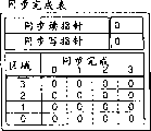
Here hypothesis: the sync mark that is used for each inlet has 4 grade 0 to 3, has 4 grades finishing the mark of finishing synchronously that is used for each inlet (corresponding to each of memory area 0 to 3) in the table 12 synchronously.(SYNC) reads pointer 161 and points out which rank of is performed synchronously.Write pointer 162 synchronously and point out a synchronisation stage, this be by read synchronously level that pointer points out be performed after execution.
Because synchronous operation is processed with the order that receives, so pointer 161 and 162 is controlled in the mode identical with general fifo buffer.Each scoring plug is only sent following operation, that is: they be in one state by the corresponding sync mark of the synchronous operation of reading pointer 161 regulation.When not occurred by the inlet of the level of reading pointer 161 regulation synchronously in all memory banks, pointer adds 1.
When finishing in the table 12 allly when finishing mark synchronously and all being in " 0 " state synchronously, all synchronous operations are done, and all sync marks in all scoring plug 100,110,120 and 130 all are in " 0 " state.Therefore, send an operation according to resulting result under the situation about not being used synchronously therein.When having received a synchronous operation, if having at least a synchronisation stage not to be used, so, received synchronous operation is not carried out and tries and carry out general synchronous processing again.When all synchronisation stage all are used, follow-up synchronous operation will be tried again.
Figure 24 shows the operation of following situation, that is: using level 3 and use level 0,1 and 2, the scoring plug 100,119 and 120 in memory area 0,1 and 2 to have effective inlet and scoring plug 130 in memory area 3 effective inlet not.The level 1 and 2 of all invalid sync marks all is configured to " 0 " and is not used.As for level 3, the sync mark that only is useful on inlet No.0 in the memory area 0 is in one state, and all sync marks in other memory area all are in " 0 " state.This means that under the situation of the operation before sending level 3 synchronous operations, only the inlet No.0 in memory area 0 is not used.
Point out handling at present level 3 at the pointer of finishing in the table 12 synchronously 161 of reading synchronously.Import a new synchronous operation in the area 0 that writes pointer 162 regulations in the table 12 synchronously by finishing synchronously.Write pointer synchronously and add 1, expression level 1.
In addition, in the level 0 of the sync mark that is used for the effective inlet of indivedual scoring plug, one " 1 " is set.In Figure 24, the effective inlet in memory area 0,1 and 2 is configured to " 1 ".Simultaneously, one " 1 " is set in 0, this means also not finishing synchronously of level 0 in the level of finishing in the table with memory area 0,1 and 2 corresponding synchronous.After this since in Figure 24 just at execution level 3, so, be used for before the operation of memory area 0 inlet No.0, can not sending operation sending.In having sent memory area 0 inlet No.0 the time, level 3 finish synchronously is so the level 3 in the memory area 0 is reset to " 0 " in the table 12 finishing synchronously.Because reading pointer 161 synchronously adds 1, expression level 0 so the sync mark of sending level 0 in order is configured to the operation of " 1 ", whereby, is performed with the synchronous processing that allows level 0.When all sync marks of each grade all were in " 0 " state, the synchronous operation of these grades all was done.Therefore, finishing table 12 synchronously can omit.
Below, explain the operation of the 3rd embodiment in further detail.
At first, explain that with reference to Figure 25 in the 3rd embodiment CPU1 has sent the processing under the memory reference instruction situation.
The memory reference instruction of being sent by CPU1 is sent to Bus Interface Unit 3 through bus 2.Bus Interface Unit 3 sends the memory reference instruction that is received to Memory Controller 10 (step S51).
When the memory reference instruction that is received was a memory reference instruction except that synchronic command, Memory Controller 10 was selected a corresponding scoring plug according to the address of the memory reference instruction that is received from scoring plug 100,110,120 and 130.In addition, Memory Controller 10 selects its significant notation to be configured to the inlet of " 1 " (empty inlet) from all inlets on selected scoring plug.After this, Memory Controller 10 is imported the memory reference instruction (step S52) that is transmitted in selected inlet.
When the input store access instruction, Memory Controller 10 is the operational code and the address of input store access instruction not only, and, also this significant notation is arranged to " V ", being used for wherein having imported the inlet of described instruction, and sync mark 0,1,2 and 3 is reset to " 0 ".
When from Bus Interface Unit 3, having received synchronic command, Memory Controller 10 will be used for all significant notations of in selected scoring plug, importing and be configured to the relevant sync mark n (n=0/1/2/3) of the inlet of " V " and be arranged to " 1 ".
In addition, under the control of body performance element 108,118,128 and 138, Memory Controller 10 is selected an inlet and send an instruction in this inlet from scoring plug.
When selected at the inlet (memory reference instruction) of step S52 input and in this inlet, sent instruction (step S53 in the time of YES), is used to do the sent mark that selection enters the mouth and is configured to " NO " (step S54).Utilize Bus Interface Unit 3, Memory Controller 10 and body performance element to carry out the operation of being sent.
After the finishing dealing with of memory reference instruction, Memory Controller 10 will be stored in the significant notation that is used in scoring plug is performed the inlet of memory reference instruction and be arranged to " 1 ", and sync mark 0,1,2 and 3 is reset to " 0 " (step S55).Handle by means of this, wherein imported the inlet that is performed memory reference instruction and be configured to freely.
By above-mentioned processing, the memory reference instruction that transmits from CPU1 is performed.
Below, send the processing of instruction respectively to corresponding scoring plug 00,110,120 and 130 with reference to Figure 26 narration each from body performance element 108,118,128 and 138.
Consider following interface, that is: in this interface, imported the memory reference instruction that will be issued on scoring plug, whether the significant notation that the body performance element at first is identified for relevant inlet is in " I " state (step S61).When the significant notation that is used for relevant inlet is in one state, because relevant inlet is invalid, so the body performance element determines that the memory reference instruction in relevant inlet can not be issued (step S62).
(step S61, in the time of NO), the body performance element is identified for sending of relevant inlet and marks whether to be in " NO " state (step S63) when the significant notation that is used for relevant inlet is in " V " state.When being used for the sending mark and be in " NO " state of relevant inlet, the body performance element is determined that the instruction in relevant inlet has been issued or owing to is not satisfied the condition of sending and not have be correlated with and send memory reference instruction (step S64) in entering the mouth.
When the mark that sends that is used for relevant inlet is in " YES " state (step S63, NO) time, the body performance element is determined by " whether SYNC reads item " SYNC COMPLETION " that pointer points out has and be used for finishing a plurality of " 0 " (the step S65) of table 12 All Ranges synchronously.Because " SYNC COMPLETION " have a plurality of " 0 " that are used for All Ranges and mean also and do not transmit synchronic command from CPU1, so the body performance element determines that the memory reference instruction in relevant inlet can be issued (step S66).
When item " SYNC COMPLETION " only has one 1 (the step S65 that is used for finishing synchronously any one zone in a plurality of zones of table 12, NO) time, the body performance element is determined to read " 0 " state (step S67) whether sync mark that pointer points out is in the sync mark 0 to 3 that is used for relevant inlet by SYNC.When the sync mark of being pointed out by the SYNC output pointer is in " 0 " state, because instruction in relevant inlet is a memory reference instruction of importing in described scoring plug after Memory Controller 10 has received a synchronic command, so the body performance element does not send memory reference instruction (step S68).
When SYNC by reading sync mark that pointer points out when being in one state (step S68.NO), because the instruction in relevant inlet is the memory reference instruction of an input before synchronic command is transmitted, so the body performance element determines that the memory reference instruction in relevant inlet can be issued (step S69).
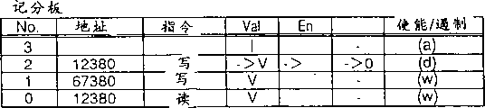
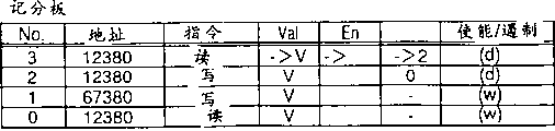
Explained later in the 3rd embodiment, the processing of Memory Controller 10 when CPU1 transmits following instruction with ascending order:
(1)Read?12380
(2)SYNC
(3)Write?67830
(4)SYNC
(5)Write?abc80
Figure 27 A inputs to the data item of area 0 and finishes table 12 synchronously to what 33B showed in scoring plug 100.
In 33B, the item of pointing out " ISSUE ENABLE/DISABLE " in each inlet keeps being illustrated in the information that body performance element among Figure 26 is determined the result, and is as follows: (a) corresponding to the definite result at Figure 26 step S62 place at Figure 27 A; (b) corresponding to definite result at step S64 place; (x) corresponding to definite result at step S66 place; (c) corresponding to definite result at step S68 place; (y) corresponding to definite result at step S69 place.This makes that understanding operation is more prone to.But in fact, this only needs to keep pointing out the information of an instruction " ISSUE ENABLE/DISABLE ".
Figure 27 A and 27B show scoring plug 100 and finish the virgin state of table 12 synchronously.Therefore, the inlet of all on scoring plug 100 all is not used (sky).On scoring plug 100, be in all inlets under " ISSUEENABLE/DISABLE " data of input expression " ISSUE DISABLE ".This is corresponding to (a), and it means that this inlet is invalid when body performance element 108 is carried out the processing of Figure 18.Afterwards, there is not the inlet that can be issued.
Figure 28 A and 28B show and are transmitting the scoring plug 100 under the situation of instruction (1) " Raed 12380 " from Bus Interface Unit 3 and finishing table 12 synchronously.Here, Memory Controller 10 is selected empty inlet No.0 and import this instruction in this inlet from the scoring plug 100 of the corresponding area 0 in address that is used for and instruction " Read 12380 ".Inlet No.0 on scoring plug 100 can be issued.
Figure 29 A and 29B show at Memory Controller 10 and have received the scoring plug 100 under synchronic command (2) " SYNC " situation and finished table 12 synchronously." 1 " is arranged in the sync mark 0 that Memory Controller 10 will effectively enter the mouth in scoring plug 100 in (" Val " under " V ").Write one " 1 " is set in the pointer finishing SYNC in the table 12 synchronously.Finish mark at the SYNC that is used for area 0 one " 1 " is set.The inlet that body performance element 108 can send is inlet No.0.
After this Figure 30 A and 30B show and have received the scoring plug 100 under the situation of instruction (3) " Write 67380 " and finished table 12 synchronously at Memory Controller 10.Memory Controller 10 is from corresponding to selecting empty inlet No.1 the scoring plug of the area 0 of a designated presumptive address.Described presumptive address comprises the address by instruction " Write 67380 " appointment.After this, Memory Controller 10 is imported described instruction in selected inlet.Inlet No.0 on scoring plug 100 and inlet No.1 can be issued.
Figure 31 A and 31B show at Memory Controller 10 and have received the scoring plug 100 under second synchronic command (4) " SYNC " situation and finished table 12 synchronously.Memory Controller 10 will with write the corresponding sync mark of pointer 1 and be arranged in and be used on the scoring plug 100 effectively " 1 " of the sync mark 0 to 3 of inlet (" V " under " Val ") finishing SYNC in the table 12 synchronously.After this, write one " 2 " are set in the pointer finishing SYNC in the table 12 synchronously.Finish mark at the SYNC that is used for area 0 one " 1 " is set.The inlet that the body performance element can send is inlet No.0.
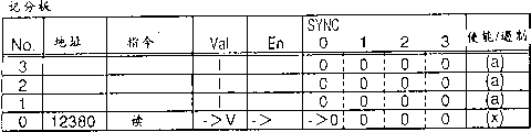
Figure 32 A and 32B show at Memory Controller 10 and have received the scoring plug 100 under instruction (5) " Write abcd80 " situation and finished table 12 synchronously.Memory Controller 10 is from corresponding to selecting an empty inlet No.2 the scoring plug 100 of the area 0 of a designated presumptive address.Described presumptive address comprises the address of being pointed out by instruction " Write abcd80 ".Memory Controller 10 is imported this instruction in selected inlet.Only the inlet No.0 on scoring plug 100 can be issued.This is that is: send (1), (3) and (5) because the instruction of being imported is in the following sequence.
Figure 33 A and 33B show body performance element 108 inlet send among the No.0 one under the instruction situation scoring plug 100 and finish table 12 synchronously.In scoring plug 100, " Val " is configured to " I ", and " En " is configured to " NO ", and SYNC mark 0 and 1 is reset to " 0 ".This set becomes freely inlet No.0.Have, finish in the table 12 synchronously, SYNC reads the SYNC completion mark that pointer is configured to " 1 " and is used for area 0 and is reset to " 0 ".
Even above-mentioned processing makes under situation about sending more than an instruction, also can handle according to the order that described instruction is issued.
(the 4th embodiment)
As shown in figure 34, fourth embodiment of the invention be in Memory Controller 10, provide one therein for every grade can both be provided with independent synchronous condition finish synchronously table and one be provided with multistage finish mark (SYNC finishes) synchronously finish table synchronously, described Memory Controller 10 has the scoring plug that is provided with multistage sync mark (SYNC mark).The 4th embodiment carries out finishing of synchronous processing with unordered processing mode, whereby, realizes reducing the function of synchronous processing overhead.Before all synchronisation stage were used, the subsequent synchronisation operation can not try again.
In other words, the 4th embodiment is added to multistage synchronous operation on the 3rd embodiment.Utilize this structure, under the situation of different synchronous operations, carry out and the second embodiment identical operations, and synchronous operation is presented one " Null " the preceding.(for example, by the synchronous processing of same processor execution or the synchronous processing of carrying out at identical address) sets synchronous operation the preceding and execution and the 3rd embodiment identical operations under the situation of identical synchronous operation.Therefore, under the situation of independent synchronous condition, carry out synchronous operation, thereby cause the minimizing of synchronous processing overhead with no sequential mode.
Below, with reference to accompanying drawing 34 concise and to the point the 4th embodiment that describe.
As shown in figure 34, the 4th embodiment have one be provided with synchronous condition table 163 finish table 12 synchronously, described synchronous condition table 163 points out to be used for the synchronous condition (in this case, pointing out same address) of synchronisation stage 0 to 3 each grade.This makes independent synchronous condition to be carried out individually
Utilize the 4th embodiment, when synchronous condition be read from same address and write to same address fashionable, synchronous condition to other memory area without any effect.For example, from read and write under the data conditions to an address of memory area 0 (for example, address 100), synchronous operation is issued, memory area 1,2 can be operated under state identical when not having synchronous condition with 3.In this case, during a synchronous operation of address in sending at memory area 2 (for example, address 1008), it can be independent of is preceding sending to the synchronous operation of memory area 0 and is handling independently.
On synchronous condition being added to each level, the operation of this embodiment is identical with the 3rd embodiment.Under the state of Figure 34, when synchronous condition is set to synchronous condition 0 and 3, point out that the SA of identical address is used as synchronous condition.Because memory area 3 do not satisfy synchronous condition, so, the operation that after this obtains can be carried out and finishing of other memory area synchronous operation needn't be waited for.If synchronous condition 3 is " being used for all addresses ", so, the inlet in memory area 3 will send when synchronous condition 3 is done.When all synchronisation stage that are used for each grade had all been finished, the synchronous processing of that one-level was done.Therefore can omit and finish table synchronously.
As mentioned above, when the 4th embodiment is applied to having the Memory Controller of bank structure, has at different bank under the situation of different synchronous conditions and also can on the basis of memory bank, carry out synchronous processing independently.
Below, be further explained in detail the operation of the 4th embodiment.
Sent the processing that processing under the memory reference instruction situation is similar to the 3rd embodiment shown in Figure 25 at CPU1 among the 4th embodiment.So the detailed description of the 4th embodiment will be omitted.
Below, each place that is described in body performance element 108,118,128 and 138 with reference to accompanying drawing 35 sends the processing of instruction respectively to scoring plug 100,110,120 and 130.
Consider following inlet, in this inlet, imported the instruction that will be issued on scoring plug, whether the significant notation that the body performance element at first is identified for relevant inlet is configured to " V " (step S71).When the significant notation that is used for relevant inlet was configured to " I ", the body performance element was determined: because relevant inlet is invalid, so the memory reference instruction in relevant inlet can not be issued (step S72).
(step S71, in the time of YES), whether the enable flag that the body performance element is identified for relevant inlet is configured to " YES " (step S73) when the significant notation that is used for effectively entering the mouth is in " V " state.
(step S73, in the time of NO), the body performance element is determined: the memory reference instruction in relevant inlet is not satisfied and is sent this memory reference instruction of conditioned disjunction and be issued when the significant notation that is used for relevant inlet is configured to " NO ".About the former, have following situation, that is: write when instruction when execute store, write data can not be transmitted to Memory Controller or try to find out device can not determine to storer write request response.About the latter, when the execute store sense order, the request of reading is transmitted to DRAM, but requested sense data does not arrive Memory Controller.Its result, the body performance element can not be emitted in the memory reference instruction (step S74) in the relevant inlet.
When the enable flag that is used for relevant inlet was configured to " YES ", whether all " SYNC COMPLETION ENTYIES " that the body performance element determines to finish synchronously all synchronisation stage in the table 12 were in " 0 " state (step S75).Because being in " 0 " state, all " SYNC COMPLETIONENTRIES " mean that the synchronous operation that relates to the corresponding zone of body performance element finishes, so the body performance element determines that the memory reference instruction in relevant inlet can be issued (step S76).
When one or more " the SYNC COMPLETION ERTRY " on all synchronisation stage are configured in the table 12 finishing synchronously " 1 " time (step S75 NO), determines to S84 that memory reference instruction can be issued maybe according to following step S77 and can not carry out.Shown in the loop of Figure 35, by means of step S78, S80, the processing of S82 and S84 determines whether memory reference instruction can be issued according to synchronizing sequence.In fact, above-mentioned steps is an executed in parallel on the execution hardware of the 4th embodiment.That is: carrying out hardware is not based on the pointer (pointer " j ") relevant with work.Pointer shown in Figure 35 " j " has adopted the mode of flow chart description for simplicity, and in Figure 34 not shown pointer " j ".
The body performance element is at first read the synchronous condition of being sent, with the order (step S77) of definite synchronous condition that also is not performed.Utilize SYNC to read first synchronous condition that pointer 162 is pointed out the synchronous condition that also is not performed.In the step S77 of Figure 35, be provided with and read the value that pointer 162 is pointed out being used for the pointer of work " J " by SYNC.
After the synchronous condition of in the end sending was read out, the body performance element is determined: a plurality of SYNC marks on the synchronisation stage that enters the mouth described in the scoring plug " j " were arranged to " 1 " (step S78) respectively.(step S78 is in the time of YES), because memory reference instruction is to send before the synchronic command of synchronisation stage " j ", so the memory reference instruction of relevant inlet can be performed (step S79) when the relevant SYNC mark that enters the mouth is configured to " 1 ".
(step S78, in the time of NO), the body performance element determines whether relevant inlet is a synchronous target instruction target word (step S80) on synchronisation stage " j " when the relevant SYNC mark that enters the mouth is not configured to " 1 ".That is: it determines that whether described relevant inlet is complementary with the SYNC condition of SYNC level " j ".When relevant inlet is that (step S80, in the time of YES), the memory reference instruction of relevant inlet can not be performed (step S81) to a synchronic command.
When relevant inlet is not that (step S80, in the time of NO), the body performance element determines that a synchronisation stage will carrying out afterwards in synchronisation stage " j " is whether with write the synchronisation stage that pointer 162 points out by SYNC consistent to a synchronic command.Synchronisation stage " j " synchronisation stage afterwards with write the corresponding to state of synchronisation stage that pointer 162 points out by SYNC and mean that in synchronisation stage " j " synchronisation stage afterwards be last synchronisation stage.Because relevant inlet does not satisfy last synchronous condition, so the memory reference instruction of relevant inlet can be performed (step S83).
When synchronisation stage " j " afterwards with the synchronisation stage that is performed with write synchronisation stage that pointer 162 points out by SYNC when inconsistent be not last synchronisation stage owing to follow in synchronisation stage " j " synchronisation stage afterwards, so, will analyze the subsequent synchronisation level.In Figure 35, work pointer " j " is increased (step S84).Step 84 is prescribed as follows: do not carry out the memory reference instruction of relevant inlet, handle so that remain the loop of step S78, S80, S82 and S84.
In the 4th embodiment, can increase by one with synchronisation stage change corresponding correlation table, be used for each inlet of scoring plug.Correlation table is pointed out to meet and same processor purposes (processor ID meets) such as the address.In this case, when importing the instruction that is transmitted in scoring plug, the body performance element compares the address and the processor ID of this address and this processor ID and this other inlet of scoring plug.When meeting generation, in the table on relevant inlet significant notation is set.Otherwise then significant notation is eliminated.In this modification, suppose that N1 points out the slogan of going into of scoring plug, number number of comparer is the sequence number of N1.
In described modification, description related to determining that memory access sends the synchronous processing on the basis.At first, the row value of correlation table is carried out NOR-operation (#1).Finish on the table each regional value synchronously at SYNC and carried out exclusive disjunction (#2) according to synchronous condition respectively.Logical OR inverse result in #1 and the logical OR operation result in #2 are carried out and computing (#3).According to all synchronous condition, all the logic and operation results in #3 are carried out exclusive disjunction (#4).
Be stored in the value that SYNC finishes in the table and be carried out exclusive disjunction (#5).When the result of the logical OR computing in #5 is " 0 ", owing to be not performed synchronously, so the condition that is used to carry out is the logic and operation between " Val " mark and " En " mark.When the logical OR operation result in #5 is " 1 " owing to can be performed synchronously, so, the condition that is used for carrying out be between " Val " and " En " the logical and result and at #4 logical OR result's logical and.
At last, the logical OR in #4, " En " mark and " Val " mark are carried out logic and operation (#6).The result of logic and operation is that the inlet of " 1 " can be issued in #6.
Explained later is the processing of Memory Controller 10 when CPU1 transmits following instruction with ascending order in the 4th embodiment:
(1)Read?12380
(2)SYNC
(3)Write?67830
(4)Write?12380
(5)SYNC
(6)Write?abcd80
Figure 36 A shows to import in scoring plug 100 to 42B and offers the data item of area 0 and finish table 12 synchronously.
The assumes synchronization condition is identical with the synchronous condition of second embodiment.
In 42B, the item of pointing out instruction " ISSUE ENABLE/DISABLE " in each inlet keeps being illustrated in body performance element among Figure 35 and determines that result's information is as follows at Figure 36 A: (a) corresponding to definite result at step S72 place in Figure 35; (b) corresponding to definite result at step S73 place; (x) corresponding to definite result at step S75 place; (y) corresponding to definite result at step S78 place; (c) corresponding to definite result at step S80 place; (z) corresponding to definite result at step S82 place.This makes that understanding operation is more prone to.But in fact, this only needs to be kept for to point out the information of " the ISSUE ENABLE/DISABLE " of an instruction.
Figure 36 A and 36B show scoring plug 100 and finish the virgin state of table 12 synchronously.Therefore, the inlet of all in scoring plug 100 all is not used (sky).In all inlets on scoring plug 100 under " ISSUE ENABLE/DISABLE ", the data of input expression ISSUE DISABLE.This is corresponding to (a), and it means that described inlet is invalid when body performance element 108 is carried out operation shown in Figure 35.After this, the inlet that can be issued will be no longer included.
Figure 37 A and 37B show and are transmitting the scoring plug 100 under the situation of instruction (1) " Read 12380 " from bus structure unit 3 and finishing table 12 synchronously.Here, Memory Controller 10 is selected an empty inlet No.0 from the scoring plug 100 of the corresponding area 0 in address that is used for and instruction " Read 12380 ", and the described instruction of input in this inlet.Inlet No.0 on scoring plug 100 can be issued
Figure 38 A and 38B show at Memory Controller 10 and have received the scoring plug 100 under synchronic command (2) " SYNC " situation and finished table 12 synchronously.Memory Controller 10 will be on scoring plug 100 effectively the sync mark 0 in the inlet (" V " under " Val ") be arranged to " 1 ".Write one " 1 " is set in the pointer finishing SYNC in the table 12 synchronously.To be arranged to " 1 " with the corresponding SYNC mark 0 of area 0.The inlet that body performance element 108 can send is inlet No.0.
After this Figure 39 A and 39B show and have received the scoring plug 100 under the situation of instruction (3) " Write 67380 " and finished table 12 synchronously at Memory Controller.Memory Controller 10 is selected an empty inlet No from the scoring plug 100 of the corresponding area 0 in address that is used for and instruction " Write 67380 ", and 1, and the described instruction of input in this inlet.Inlet No.0 on scoring plug 100 and inlet No.1 can be issued.
Figure 40 A and 40B show at Memory Controller 10 and after this receive instruction 94) scoring plug 100 under " Write 12380 " situation and finish table 12 synchronously.Memory Controller 10 is selected an empty inlet No.2 from the scoring plug 100 of the corresponding area 0 in address that is used for and instruction " Write 12380 ", and the described instruction of input in this inlet.On scoring plug 100, have only inlet No.0 and inlet No.1 to be issued.
Figure 41 A and 41B show at Memory Controller 10 and have received the scoring plug 100 under second synchronic command (5) " SYNC " situation and finished table 12 synchronously.Memory Controller 10 will with write " 1 " that the corresponding sync mark of pointer is arranged in from 0 to 3 the sync mark that is used for all inlets (" V " under " Val ") on the scoring plug 100 finishing SYNC in the table 12 synchronously.After this, write " 2 " are set in the pointer finishing in the table 12 SYNC synchronously.The SYNC mark that is used for area 0 is configured to " 1 ".The inlet that body performance element 108 can be carried out only is inlet No.0 and inlet No.1.
After this Figure 42 A and 42B show and have received the scoring plug 100 under instruction (6) " Write abcd80 " situation and finished table 12 synchronously at Memory Controller 10.Memory Controller 10 is selected an empty inlet No.3 from the scoring plug 100 of the corresponding area 0 in address that is used for and instruction " Write abcd80 ", and the described instruction of input in this inlet.Here, write setting " 2 " in the pointer at the SYNC that finishes in the table 12 synchronously.The SYNC that is used for area 0 finishes mark 1 and is configured to " 1 ".The inlet that body performance element 108 can send only is inlet No.0 and inlet No.1.
Above-mentioned processing makes Memory Controller 10 not only can receive a plurality of instructions, and, can also send memory reference instruction according to predetermined synchronous condition.
(the 5th embodiment)
The fifth embodiment of the present invention is to have saved finishing table synchronously and removed sync mark from scoring plug 11 in the Memory Controller 10 on the basis of first embodiment.
Particularly, utilize the 5th embodiment, synchronous condition is applied in all operations (not to be considered synchronously).The operation that has synchronous condition when execution has only the operation of satisfying synchronous condition always to be performed when (being used for identical request or identical address), and does not consider to carry out synchronously.This not only makes and can omit sync mark and finish table synchronously, and, can avoid the operation after synchronic command to be tried again, whereby, improved the processing power of system.When determining in the weak order mode rather than with no sequential mode executive condition, the 5th embodiment is effective especially.That is: owing to guaranteeing that in a general system the accessed order of identical address has been enough, so the 5th embodiment is effective especially.In order to carry out the 5th embodiment, the accessed order of identical address (part of a plurality of addresses can be compared) is constant, perhaps needs one to be used to the device of avoiding order that writes and write and the order of reading and writing (sequence notation, aftermentioned) to change.
Below with reference to Figure 43 brief explanation the 5th embodiment.
As shown in figure 43, utilize the 5th embodiment, synchronous condition is added in all operations.Sync mark and finish synchronously the table be omitted.Be used for pointing out that the sequence notation 103 in preceding operation is added to scoring plug 100,110,120 and 130.
For example, when when preceding operation has identical address, in described inlet, be arranged on the slogan of going into of preceding operation.When preceding operation has been issued or is invalid, sequence notation is disabled (-), so that described operation can be issued.
For example, under all synchronous operation all is the situation relevant with " read from same address and write to same address ", when being written into visit of arriving identical address of time place's input of described inlet an operation, going into slogan and be set to identical with sequence notation.When importing, go into slogan and be configured to sequence notation for one that is transfused at last more than a visit of arriving identical address.
In case in pre-treatment or sequence notation is effectively, relevant inlet operation just can not be issued.When preceding operation is processed, the sequence notation that is used for follow-up inlet promptly is eliminated, and, can send follow-up inlet.If after an inlet has been transfused to, delete it again for some reason, so, described inlet is remained to avoid because deletion makes storage arrangement locked as NOP.
Figure 43 shows the situation of always carrying out synchronous processing at an identical address.For example, in memory area 0,4 same addresses that effectively enter the mouth conduct interviews.Utilize the 5th embodiment, if always carry out at same address synchronously, so, the preceding operation on same address is stipulated by a sequence notation.
Under state shown in Figure 43, according to the inlet No.1, the inlet No.0, the inlet No.7 and the inlet No.5 order same address is conducted interviews.Though inlet No, 0 finishes as a bus operation,, be transfused to as an inlet No.1 in preceding operation, so, the No that before the processing of inlet No.1 is not finished, enters the mouth, 0 can not be issued.Similarly, inlet No.7 can not be issued before the processing of inlet No.0 is not finished.Inlet No.5 can not be issued before the processing of inlet No.7 is finished.This has guaranteed to carry out in the following order each inlet: inlet No.1, inlet No.0, inlet No.7 and inlet No.5.
Because bus operation is not finished, No.7 is deleted for inlet.If No.7 is deleted for inlet, so, operation changes to " NOP " from " writing ", changes to the significant notation in the inlet of " I " to be substituted in, and this has been avoided being issued from the deletion of disable inlet No.5.
Below, explain the operation of the 5th embodiment in detail.
At first, explain in the 5th embodiment at CPU1 with reference to Figure 44 and sent operation under the memory reference instruction situation.
The memory reference instruction of being sent by CPU1 is transmitted to bus interface 3 through bus 2.Bus interface 3 sends the memory reference instruction that is received to Memory Controller 10 (step S91).
When the memory reference instruction that is received was a memory reference instruction except that synchronic command, Memory Controller 10 was selected a corresponding scoring plug according to the address of institute's reception memorizer access instruction from scoring plug 100,110,120 and 130.And then Memory Controller 10 selects a significant notation to be configured to the inlet of " I " (empty inlet) from all inlets on selected scoring plug.Then, Memory Controller 10 is imported the memory reference instruction (step S92) that is transmitted in this selected inlet.
When the described memory reference instruction of input, Memory Controller 10 not only will be imported the operational code and the address of this memory reference instruction, is marked as " V " but also described effective value will be established.
According to synchronous condition, Memory Controller 10 determines whether to have in the relevant inlet on this scoring plug the operation relevant with this memory reference instruction or need be by synchronous operation (step S93).If have needs by synchronous operation, so, Memory Controller 10 will be imported according to the sequence notation needs and be gone into slogan (step S94) by synchronous (preceding) last input operation.If there is no need by synchronous operation, then Memory Controller 10 is used in the sequence notation invalid (step S95) of relevant inlet.
When (preceding) operation that slogan points out by going into of importing in proper order by inlet had been finished, described sequence notation was disabled (step S96).
In addition, under the control of body performance element 108,118,128 and 138, Memory Controller 10 is selected an inlet and send described instruction (step S97) selected inlet from scoring plug.
Selected and instruction in this inlet sends that (step S97, in the time of YES), the sent mark that is used for selected inlet is configured to " NO " (step S98) when the inlet that is transfused to (memory reference instruction).Utilize Bus Interface Unit 3, Memory Controller 10 and body performance element to carry out the memory reference instruction of being sent.
After the processing of memory reference instruction is done, Memory Controller 10 not only will be stored in the significant notation that is used in the inlet that scoring plug is performed memory reference instruction and be arranged to " I ", and, also will wherein import the inlet that is performed instruction and be arranged to freely (step S99).If point out that the entry sequence mark of processed inlet exists, so, Memory Controller 10 will make this sequence notation invalid.
By above-mentioned processing, carry out the memory reference instruction of sending from CPU1.
Below, be described in each place's corresponding processing of sending instruction in scoring plug 100,110,120 and 130 respectively of body performance element 108,118,128 and 138 in conjunction with Figure 45.
Consider following inlet, in this inlet, imported the memory reference instruction that need be issued on scoring plug, whether the significant notation that the body performance element at first is identified for relevant inlet is in " I " state (step S101).When the significant notation that is used for relevant inlet was in " I " state, the body performance element was determined owing to should relevant inlet being invalid, so the memory reference instruction in relevant the inlet can not be issued (step S102).
(step S101, in the time of NO), the body performance element is identified for sending of relevant inlet and marks whether to be in " NO " state (step S103) when the significant notation that is used for relevant inlet is in " V " state.When being used for the sending mark and be in " NO " state of relevant inlet, the body performance element is determined that the instruction in relevant inlet has been finished or owing to is not satisfied the condition of sending and not have be correlated with and send memory reference instruction (step S104) in entering the mouth.
When the sending instruction in relevant inlet is in " YES " state (step 103, in the time of NO), the body performance element determines that sequence notation is invalid (step S105).When sequence notation was invalid, this means did not need synchronous processing, and perhaps the pre-treatment of relevant inlet is finished, so the body performance element determines to be emitted in the memory reference instruction (step S106) in the relevant inlet.
When sequence notation is effective (step S105 NO), this means and carries out synchronous processing, or waiting for relevant inlet in pre-treatment, so the body performance element determines to be emitted in the memory reference instruction (step S107) in the relevant inlet.
Explained later is the processing of Memory Controller 10 when CPU1 and the following instruction of ascending order execution in the 5th embodiment:
(1)Read 12380
(2)Write 67830
(3)Write 12380
(4)Read 12380
(5)Read abcd70
Figure 46 the data item that provides and import in scoring plug 100 for area 0 is provided and finishes table 12 synchronously to Figure 53.
Suppose: synchronous condition is " can send writing/sense order at same address after pre-treatment is done ".This is such condition, that is: when have at same address in preceding memory reference instruction the time, always can not be issued at the writing of same address/sense order and must not consider synchronic command, simultaneously, when not having in preceding memory reference instruction, write/sense order can be issued.
In Figure 46 to 53, the item of pointing out " the ISSUE ENABLE/DISABLE " that instruct in each inlet keeps being expressed as follows the information that in Figure 45 body performance element is determined the result: (a) corresponding to definite result at step S102 place in Figure 45; (b) corresponding to definite result at step S104 place; (w) corresponding to definite result at step S106 place; With, (d) corresponding to definite result at step S107 place.This makes that understanding operation is more prone to.But in fact, described the information that only needs to keep to point out " the ISSUE ENABLE/DISABLE " that instruct.
Figure 46 shows the virgin state of scoring plug 100.Therefore, the inlet of all in scoring plug 100 all is not used (sky).In all inlets on scoring plug 100 under " ENABLE/DISABLE ", the data of pointing out " ISSUE DISABLE " have been imported.This is corresponding to (a), and it means that described inlet is invalid when the body performance element is carried out processing shown in Figure 45.Therefore, will can be issued less than inlet.
Figure 47 shows in the scoring plug 100 that has transmitted from interface unit 3 under the situation of instruction (1) " Read 12380 ".Here, Memory Controller 10 is selected an empty inlet No.0 and import described instruction in this inlet from the scoring plug 100 of the corresponding area 0 in address that is used for and instruction " Read 12380 ".Inlet No.0 on scoring plug 100 can be issued.
Figure 48 shows at Memory Controller 10 after this and has received scoring plug 100 under the situation of instruction (2) " Write 67380 ".Memory Controller 10 is selected an empty inlet No from the scoring plug of the corresponding area 0 in address that is used for and instruction " Write 67380 ", and 1 and this instruction of input in selected inlet.Inlet No.0 on scoring plug 100 and inlet No.1 can be issued.
Figure 49 shows at Memory Controller 10 after this and has received scoring plug 100 under the situation of instruction (3) " Write 12380 ".Memory Controller 10 is selected an empty inlet No from the scoring plug of the corresponding area 0 in address that is used for and instruction " Write 12380 ", and 2 and this instruction of input in selected inlet.Because address 12380 is identical with the address that is used in the No.0 memory reference instruction that enters the mouth, so, the mark (data) of the No.0 that points out to enter the mouth be arranged for the entering the mouth sequence notation of No.2.According to synchronous condition, only inlet No.0 on scoring plug 100 and inlet No.1 can be issued.
Figure 50 shows at Memory Controller 10 and has received scoring plug 100 under the situation of instruction (4) " Read 12380 ".Memory Controller 100 is selected an empty inlet No.3 from the scoring plug 100 of the corresponding area 0 in address that is used for and instruction " Read 12380 ", and this instruction of input in selected inlet.Because address 12380 is identical with the address that is used in inlet No.0 and inlet No.2 memory reference instruction, so, the last input mark (data) of No.2 be arranged for the entering the mouth sequence notation of No.3 that enters the mouth pointed out.According to synchronous condition, only inlet No.0 on scoring plug 100 and inlet No.1 can be issued.
Figure 51 shows at body performance element 108 and has selected inlet No.0 on the scoring plug 100 and instruction (1) " Read 12380 " to be issued scoring plug 100 under the situation.Memory Controller 10 is provided with on this scoring plug " En " and arrives inlet No.0 under " NO ", and the No.0 that will enter the mouth is arranged to freely.Only the inlet No.0 on scoring plug 100 can be issued.
Figure 52 shows when the processing that send instruction (1) " Read 12380 " scoring plug 100 under the performance.The sequence notation that Memory Controller 10 is used in scoring plug 100 upper inlet No.2 is invalid.Therefore, only inlet No.1 on scoring plug and inlet No.2 can be issued.
Figure 53 shows at Memory Controller 10 and has received scoring plug 100 under instruction (5) " Read abcd70 " situation.Memory Controller 10 is selected an empty inlet No.0 from the scoring plug 100 of the corresponding area 0 in address that is used for and instruction " Read abcd70 ", and this instruction of input in selected inlet.Only inlet No.1 on scoring plug 100 and inlet No.2 can be issued.
Above-mentioned processing makes Memory Controller 10 to select and to send memory reference instruction according to predetermined synchronous condition.
(the 6th embodiment)
Shown in Figure 54, the sixth embodiment of the present invention is as follows, that is: all memory area, or storer range of control is to be managed by a single scoring plug 200, and does not use and finish table synchronously.In other words, the 6th embodiment is such system, the mode of operation of this system's centralized management in each memory area, and simultaneously, first embodiment is such system, each memory area of this system's distributivity management.
Shown in Figure 54, the Memory Controller of the 6th embodiment 10 use a single scoring plug 200 go management system performance element BM0 in the BM3 each mode of operation and produce the control signal that is used for 4 memory areas 0 to 3.When sending synchronous operation, represent that this operation is that the mark of an operation before synchronously is configured to " 1 ", to be used as sync mark 201, whereby to discern it according to an operation after synchronously.
In addition, before synchronous processing is finished, be configured to " 1 ",, and make synchronous operation be carried out examination more whereby rejecting follow-up synchronous operation at the mark of finishing in the table 240 synchronously of finishing synchronously.Utilize so single scoring plug, when the sync mark 201 that is used for all inlets all was in " 0 " state, this just means synchronously finished.Therefore, can omit and finish table 240 synchronously.
(the 7th embodiment)
Shown in Figure 55, similar with the 6th embodiment, the seventh embodiment of the present invention uses a scoring plug 200 to go to manage the mode of operation of each memory area concentratedly and provide one to finish table 240 synchronously, finish synchronously in the table 240 at this, be provided be used for all separately inlet finish mark 241 and synchronous condition 242 synchronously.
Particularly, utilize the 7th embodiment, only (carry out synchronous processing (strong preface is handled) here, same address SA in) the operation, simultaneously, the unordered or weak order that execution is general in the operation of not satisfying synchronous condition is handled satisfying synchronous condition 242.
The difference of the 7th embodiment and the 6th embodiment is: shown in Figure 55, synchronous condition 242 is added to synchronously to be finished in the table 240.Therefore, the different centralized management methods that only are of the 7th embodiment and the 6th embodiment.The basic operation of the 7th embodiment is identical with the basic operation of second embodiment.
Utilize the 7th embodiment,, just must in scoring plug 200, import synchronous condition and whenever subsequent operation determines then whether described synchronous condition is satisfied when omitting when finishing table 24 synchronously.When the input subsequent operation, a sync mark 201 is set in scoring plug 200.Use this sync mark can stipulate three kinds of states: " synchronously ", " synchronously " and " not considering synchronously ", this helps to control.Can determine synchronous finishing according to the inlet that " synchronously " in described scoring plug, do not occur being used for.
(the 8th embodiment)
Shown in Figure 56, similar with the 6th embodiment, the eighth embodiment of the present invention is used the mode of operation of a single scoring plug 200 each memory areas of centralized management, and identical input with the 3rd embodiment is used for the inlet of multistage sync mark.Utilize the 8th embodiment, when only using a scoring plug, can omit and finish table 240 synchronously.
Shown in Figure 56, the 8th embodiment provides in scoring plug 200 and the corresponding a plurality of inlets that are used for multistage sync mark 202 of a plurality of synchronisation stage.The detail operations of the 8th embodiment is identical with the 3rd embodiment.Particularly, utilize the 8th embodiment, suppose: sync mark 202 has be used for each inlet 4 grade 0 to 3.Also can suppose to have 4 grades at the mark of finishing in the table 240 synchronously of finishing synchronously.(SYNC) reads pointer 261 and points out which rank of is performed synchronously, writes pointer 262 synchronously and points out next synchronisation stage.
When finishing table 240 synchronously and be omitted, input synchronous condition and determine when subsequent operation arrives whether described synchronous condition is satisfied in scoring plug.When importing follow-up operation, sync mark 202 is set.In this case, be used to stipulate three kinds of states: the sync mark 202 of " synchronously ", " synchronously " and " not considering synchronously " helps to control.Can determine synchronous finishing according to the inlet that " synchronously " in scoring plug, do not occur being used for.
(the 9th embodiment)
Shown in Figure 57, similar with the 6th embodiment, the ninth embodiment of the present invention uses a single scoring plug 200 to remove to manage concentratedly the mode of operation of each memory area, and the identical inlet 263 of pointing out to be used for 0 to 3 each synchronisation stage synchronous condition (same address SA in this case) that provides with the 4th embodiment.
Particularly, in the 9th embodiment, finishing synchronously according to a plurality of synchronisation stage provides the inlet 263 of pointing out a plurality of synchronous conditions in the table 240.The operation of the detail operations of the 9th embodiment and the 4th embodiment identical.
When finishing table 240 synchronously and be omitted, on scoring plug, import synchronous operation, and, determine whether to satisfy synchronous condition when subsequent operation arrives.When the input subsequent operation, sync mark 202 is set.In this case, use three kinds of states of regulation, that is: the sync mark of " synchronously ", " synchronously " and " not considering synchronously " can help to control.The inlet that can not be used for " synchronously " according to not existing in scoring plug is determined synchronous finishing.
(the tenth embodiment)
Shown in Figure 58, be similar to the 6th embodiment, the tenth embodiment of the present invention uses a single scoring plug 200 to remove to manage concentratedly the mode of operation of each memory area, and described synchronous condition is offered all operations (not considering synchronously).Utilize the tenth embodiment, when execution has the operation of the condition relevant with synchronous operation, (be used for same request or same address), always only carry out and satisfy the operation of described synchronous condition, and needn't consider to carry out synchronously.This not only makes and can omit sync mark and finish mark synchronously, and, can avoid the operation after the synchronic command to be carried out examination again, whereby, with the processing power of improvement system.
Particularly, shown in Figure 58, the tenth embodiment is applied to synchronous condition in all operations, and synchronous meter and finish table synchronously and be omitted and will be used to point out that the inlet at preceding sequence of operation mark 203 is added to scoring plug 200.For example, when when preceding operation has identical address, in described a plurality of inlets, be arranged on the slogan of going into of preceding operation.When preceding operation has been issued or has been disabled, described sequence notation is disabled (-) so that operation can be issued.The detail operations of the tenth embodiment is identical with the operation of the 5th embodiment.
As explaining up till now, utilize the present invention, in being applied to the Memory Controller of multicomputer system, the use and management table not only can diode-capacitor storage the state of visit, and, when carrying out synchronous operation, can also receive the follow-up operation operation of synchronous condition (or satisfy).Therefore, can avoid asking the unit of subsequent operation to try described request again, thereby reduce the overhead of system in the synchronous processing process.
, clearly can find some other advantages and make some modification with interior technician for this professional skill field.Therefore, the invention of the relative broad range certain illustrated that is not limited to here to be done, indication device and shown in embodiment.Therefore, under the situation of the spirit and scope that do not break away from the general inventive concept of stipulating by claims and equivalent thereof, can make various modifications.
Claims (14)
1. a Memory Controller (10) is used to respond the reception memorizer access instruction as unordered or weak order instruction and the strong preface instruction control storer of at least one synchronic command conduct, and described Memory Controller comprises:
The device of storage instruction admin table (11), described instruction admin table has a plurality of inlets of information of the executive process of the memory reference instruction that storage representation receives, each of described a plurality of inlets comprises at least one sync mark (101), and this sync mark shows whether the corresponding memory access instruction was received before synchronic command; And
Device (10), be used for according to the inlet information that comprises sync mark (101), after all memory reference instructions that received before the synchronic command are complete,, carry out the memory reference instruction that is received by carrying out the memory reference instruction that behind synchronic command, receives.
2. Memory Controller according to claim 1, also comprise a device, described device is used for order and receives each memory reference instruction of being sent, described each memory reference instruction is recorded in described instruction admin table (11), and for described each memory reference instruction corresponding synchronous mark (101) is set, this sync mark (101) shows that memory reference instruction was not received before synchronic command.
3. Memory Controller according to claim 2, also comprise a device, described device is used for receiving synchronic command and changes all memory reference instruction sync marks that are recorded in described instruction admin table (11), is received before synchronic command to show memory reference instruction.
4. Memory Controller according to claim 1, wherein each of a plurality of inlets in described instruction admin table (11) comprises also whether an execution that shows the corresponding memory access instruction finished finishes mark (105).
5. Memory Controller according to claim 1, also comprise a storage and finish the device of table (12) synchronously, this finishes a plurality of inlets that table has the information of memory access instruction synchronously, each of described a plurality of inlets has one and finishes mark synchronously, and this is finished mark shows the corresponding memory access instruction that receives before synchronic command execution synchronously and finishes.
6. Memory Controller according to claim 5, the wherein said table (12) of finishing synchronously also comprises a storage shows the information (160) of the condition of the memory reference instruction that execution receives before synchronic command inlet.
7. Memory Controller according to claim 1, each of a plurality of inlets in the wherein said instruction admin table (11) comprise that also shows a whether executable mark (106) of corresponding memory access instruction.
8. memory control methods that in computer system, uses with Memory Controller (10), be used to respond the reception memorizer access instruction as unordered or weak order instruction and the strong preface instruction control storer of at least one synchronic command conduct, described Memory Controller comprises the device of storage instruction admin table (11), this instruction admin table has a plurality of inlets of information of the executive process of the memory reference instruction that storage representation receives, and described method comprises following step:
Each that makes described a plurality of inlets comprises at least one sync mark (101), and this sync mark shows whether the corresponding memory access instruction was received before synchronic command; And
According to the inlet information that comprises sync mark (101), after all memory reference instructions that received before the synchronic command are complete,, carry out the memory reference instruction that is received by carrying out the memory reference instruction that behind synchronic command, receives.
9. method according to claim 8, also comprise this step, promptly order receives each memory reference instruction of being sent, described each memory reference instruction is recorded in described instruction admin table, and for described each memory reference instruction corresponding synchronous mark (101) is set, this sync mark (101) shows that memory reference instruction was not received before synchronic command.
10. method according to claim 9, also comprise this step, promptly receive synchronic command and change all memory reference instruction sync marks that are recorded in the described instruction admin table (11), before synchronic command, be received to show memory reference instruction.
11. method according to claim 8, wherein each of a plurality of inlets in described instruction admin table (11) comprises also whether an execution that shows the corresponding memory access instruction finished finishes mark (105).
12. method according to claim 8, wherein said Memory Controller also comprises a storage and finishes the device of table (12) synchronously, this finishes a plurality of inlets that table has the information of memory access instruction synchronously, each of described a plurality of inlets has one and finishes mark synchronously, and this is finished mark shows the corresponding memory access instruction that receives before synchronic command execution synchronously and finishes.
13. method according to claim 12, the wherein said table (12) of finishing synchronously also comprises a storage shows the information (160) of the condition of the memory reference instruction that execution receives before synchronic command inlet.
14. method according to claim 8, each of a plurality of inlets in the wherein said instruction admin table (11) comprise that also shows a whether executable mark (106) of corresponding memory access instruction.
Applications Claiming Priority (3)
| Application Number | Priority Date | Filing Date | Title |
|---|---|---|---|
| JP015726/1996 | 1996-01-31 | ||
| JP1572696 | 1996-01-31 | ||
| JP015726/96 | 1996-01-31 |
Publications (2)
| Publication Number | Publication Date |
|---|---|
| CN1175034A CN1175034A (en) | 1998-03-04 |
| CN1120425C true CN1120425C (en) | 2003-09-03 |
Family
ID=11896768
Family Applications (1)
| Application Number | Title | Priority Date | Filing Date |
|---|---|---|---|
| CN97102917A Expired - Fee Related CN1120425C (en) | 1996-01-31 | 1997-01-31 | Memory controller and memory control system |
Country Status (5)
| Country | Link |
|---|---|
| US (1) | US5881264A (en) |
| EP (1) | EP0788054B1 (en) |
| KR (1) | KR100220890B1 (en) |
| CN (1) | CN1120425C (en) |
| DE (1) | DE69733374T2 (en) |
Families Citing this family (63)
| Publication number | Priority date | Publication date | Assignee | Title |
|---|---|---|---|---|
| US6370632B1 (en) | 1997-11-18 | 2002-04-09 | Intrinsity, Inc. | Method and apparatus that enforces a regional memory model in hierarchical memory systems |
| US6260131B1 (en) * | 1997-11-18 | 2001-07-10 | Intrinsity, Inc. | Method and apparatus for TLB memory ordering |
| EP0935199B1 (en) | 1998-02-04 | 2011-05-04 | Panasonic Corporation | Memory control unit and memory control method and medium containing program for realizing the same |
| US6065086A (en) * | 1998-02-17 | 2000-05-16 | International Business Machines Corporation | Demand based sync bus operation |
| US6862635B1 (en) * | 1998-11-13 | 2005-03-01 | Cray Inc. | Synchronization techniques in a multithreaded environment |
| US6363466B1 (en) | 1999-09-13 | 2002-03-26 | Vlsi Technology, Inc. | Interface and process for handling out-of-order data transactions and synchronizing events in a split-bus system |
| KR100708096B1 (en) * | 2000-07-21 | 2007-04-16 | 삼성전자주식회사 | Bus system and execution scheduling method for access commands thereof |
| JP3857530B2 (en) * | 2001-03-09 | 2006-12-13 | インターナショナル・ビジネス・マシーンズ・コーポレーション | Job execution control device, method, and program |
| US7089405B2 (en) * | 2001-03-21 | 2006-08-08 | Sun Microsystems, Inc. | Index-based scoreboarding system and method |
| US6725314B1 (en) * | 2001-03-30 | 2004-04-20 | Sun Microsystems, Inc. | Multi-bank memory subsystem employing an arrangement of multiple memory modules |
| US7711928B2 (en) * | 2004-03-31 | 2010-05-04 | Oracle America, Inc. | Method and structure for explicit software control using scoreboard status information |
| US7409475B2 (en) * | 2004-10-20 | 2008-08-05 | Kabushiki Kaisha Toshiba | System and method for a high-speed shift-type buffer |
| US7603544B2 (en) * | 2004-12-23 | 2009-10-13 | Intel Corporation | Dynamic allocation of a buffer across multiple clients in multi-threaded processor without performing a complete flush of data associated with allocation |
| US7480781B2 (en) * | 2004-12-30 | 2009-01-20 | Intel Corporation | Apparatus and method to merge and align data from distributed memory controllers |
| EP1860568A1 (en) * | 2005-03-14 | 2007-11-28 | Matsushita Electric Industrial Co., Ltd. | Bus controller |
| JP2006331008A (en) * | 2005-05-25 | 2006-12-07 | Matsushita Electric Ind Co Ltd | Memory interface |
| US7738483B2 (en) * | 2005-09-08 | 2010-06-15 | Kabushiki Kaisha Toshiba | Systems and methods for managing communication between master and slave devices |
| US8165301B1 (en) | 2006-04-04 | 2012-04-24 | Bitmicro Networks, Inc. | Input-output device and storage controller handshake protocol using key exchange for data security |
| US7620748B1 (en) * | 2006-04-06 | 2009-11-17 | Bitmicro Networks, Inc. | Hardware assisted non-volatile memory-to-input/output direct memory access (DMA) transfer |
| KR100593425B1 (en) * | 2006-04-11 | 2006-06-28 | (주)케이제이엔지니어링 건축사사무소 | Fixing apparatus of grounding wire using telegraph pole |
| EP2021921A2 (en) * | 2006-05-17 | 2009-02-11 | Nxp B.V. | Multi-processing system and a method of executing a plurality of data processing tasks |
| US8959307B1 (en) | 2007-11-16 | 2015-02-17 | Bitmicro Networks, Inc. | Reduced latency memory read transactions in storage devices |
| JP2010020363A (en) * | 2008-07-08 | 2010-01-28 | Sony Corp | Arithmetic processing unit |
| JP2010097557A (en) * | 2008-10-20 | 2010-04-30 | Toshiba Corp | Set associative cache apparatus and cache method |
| JP5300407B2 (en) | 2008-10-20 | 2013-09-25 | 株式会社東芝 | Virtual address cache memory and virtual address cache method |
| KR101013769B1 (en) | 2008-12-16 | 2011-02-14 | 인하대학교 산학협력단 | Method and apparatus for arbitrating a bus |
| US9135190B1 (en) | 2009-09-04 | 2015-09-15 | Bitmicro Networks, Inc. | Multi-profile memory controller for computing devices |
| US8665601B1 (en) | 2009-09-04 | 2014-03-04 | Bitmicro Networks, Inc. | Solid state drive with improved enclosure assembly |
| US8447908B2 (en) | 2009-09-07 | 2013-05-21 | Bitmicro Networks, Inc. | Multilevel memory bus system for solid-state mass storage |
| US8560804B2 (en) * | 2009-09-14 | 2013-10-15 | Bitmicro Networks, Inc. | Reducing erase cycles in an electronic storage device that uses at least one erase-limited memory device |
| JP2011198091A (en) * | 2010-03-19 | 2011-10-06 | Toshiba Corp | Virtual address cache memory, processor, and multiprocessor system |
| US9372755B1 (en) | 2011-10-05 | 2016-06-21 | Bitmicro Networks, Inc. | Adaptive power cycle sequences for data recovery |
| CN102609378B (en) * | 2012-01-18 | 2016-03-30 | 中国科学院计算技术研究所 | A kind of message type internal storage access device and access method thereof |
| US8935513B2 (en) * | 2012-02-08 | 2015-01-13 | International Business Machines Corporation | Processor performance improvement for instruction sequences that include barrier instructions |
| US9043669B1 (en) | 2012-05-18 | 2015-05-26 | Bitmicro Networks, Inc. | Distributed ECC engine for storage media |
| US9582276B2 (en) * | 2012-09-27 | 2017-02-28 | Apple Inc. | Processor and method for implementing barrier operation using speculative and architectural color values |
| US9383995B2 (en) | 2013-01-25 | 2016-07-05 | Apple Inc. | Load ordering in a weakly-ordered processor |
| US9779038B2 (en) * | 2013-01-31 | 2017-10-03 | Apple Inc. | Efficient suspend-resume operation in memory devices |
| US9423457B2 (en) | 2013-03-14 | 2016-08-23 | Bitmicro Networks, Inc. | Self-test solution for delay locked loops |
| US9916213B1 (en) | 2013-03-15 | 2018-03-13 | Bitmicro Networks, Inc. | Bus arbitration with routing and failover mechanism |
| US9400617B2 (en) | 2013-03-15 | 2016-07-26 | Bitmicro Networks, Inc. | Hardware-assisted DMA transfer with dependency table configured to permit-in parallel-data drain from cache without processor intervention when filled or drained |
| US9501436B1 (en) | 2013-03-15 | 2016-11-22 | Bitmicro Networks, Inc. | Multi-level message passing descriptor |
| US10120694B2 (en) | 2013-03-15 | 2018-11-06 | Bitmicro Networks, Inc. | Embedded system boot from a storage device |
| US9672178B1 (en) | 2013-03-15 | 2017-06-06 | Bitmicro Networks, Inc. | Bit-mapped DMA transfer with dependency table configured to monitor status so that a processor is not rendered as a bottleneck in a system |
| US10489318B1 (en) | 2013-03-15 | 2019-11-26 | Bitmicro Networks, Inc. | Scatter-gather approach for parallel data transfer in a mass storage system |
| US9720603B1 (en) | 2013-03-15 | 2017-08-01 | Bitmicro Networks, Inc. | IOC to IOC distributed caching architecture |
| US9798688B1 (en) | 2013-03-15 | 2017-10-24 | Bitmicro Networks, Inc. | Bus arbitration with routing and failover mechanism |
| US9734067B1 (en) | 2013-03-15 | 2017-08-15 | Bitmicro Networks, Inc. | Write buffering |
| US9842024B1 (en) | 2013-03-15 | 2017-12-12 | Bitmicro Networks, Inc. | Flash electronic disk with RAID controller |
| US9934045B1 (en) | 2013-03-15 | 2018-04-03 | Bitmicro Networks, Inc. | Embedded system boot from a storage device |
| US9430386B2 (en) | 2013-03-15 | 2016-08-30 | Bitmicro Networks, Inc. | Multi-leveled cache management in a hybrid storage system |
| US9971524B1 (en) | 2013-03-15 | 2018-05-15 | Bitmicro Networks, Inc. | Scatter-gather approach for parallel data transfer in a mass storage system |
| US9875205B1 (en) | 2013-03-15 | 2018-01-23 | Bitmicro Networks, Inc. | Network of memory systems |
| US9952991B1 (en) | 2014-04-17 | 2018-04-24 | Bitmicro Networks, Inc. | Systematic method on queuing of descriptors for multiple flash intelligent DMA engine operation |
| US10078604B1 (en) | 2014-04-17 | 2018-09-18 | Bitmicro Networks, Inc. | Interrupt coalescing |
| US10042792B1 (en) | 2014-04-17 | 2018-08-07 | Bitmicro Networks, Inc. | Method for transferring and receiving frames across PCI express bus for SSD device |
| US10055150B1 (en) | 2014-04-17 | 2018-08-21 | Bitmicro Networks, Inc. | Writing volatile scattered memory metadata to flash device |
| US10025736B1 (en) | 2014-04-17 | 2018-07-17 | Bitmicro Networks, Inc. | Exchange message protocol message transmission between two devices |
| US9811461B1 (en) | 2014-04-17 | 2017-11-07 | Bitmicro Networks, Inc. | Data storage system |
| KR101993028B1 (en) | 2015-02-05 | 2019-06-26 | 에스케이하이닉스 주식회사 | Memory controller |
| US10552050B1 (en) | 2017-04-07 | 2020-02-04 | Bitmicro Llc | Multi-dimensional computer storage system |
| US10877888B2 (en) | 2018-09-07 | 2020-12-29 | Apple Inc. | Systems and methods for providing distributed global ordering |
| CN110806900B (en) * | 2019-04-30 | 2021-07-09 | 成都海光微电子技术有限公司 | Memory access instruction processing method and processor |
Citations (3)
| Publication number | Priority date | Publication date | Assignee | Title |
|---|---|---|---|---|
| EP0533427A1 (en) * | 1991-09-18 | 1993-03-24 | AT&T GLOBAL INFORMATION SOLUTIONS INTERNATIONAL INC. | Computer memory control system |
| US5293602A (en) * | 1990-02-01 | 1994-03-08 | Hitachi, Ltd. | Multiprocessor computer system with dedicated synchronizing cache |
| US5307320A (en) * | 1992-09-23 | 1994-04-26 | Intel Corporation | High integration DRAM controller |
Family Cites Families (7)
| Publication number | Priority date | Publication date | Assignee | Title |
|---|---|---|---|---|
| JPH0498435A (en) * | 1990-08-10 | 1992-03-31 | Toshiba Corp | Shared memory controller for computer system |
| US5488729A (en) * | 1991-05-15 | 1996-01-30 | Ross Technology, Inc. | Central processing unit architecture with symmetric instruction scheduling to achieve multiple instruction launch and execution |
| CA2083022A1 (en) * | 1991-11-22 | 1993-05-23 | Maria Pay Kudisch | Application specific integrated circuit for shared memory controller |
| US5898882A (en) * | 1993-01-08 | 1999-04-27 | International Business Machines Corporation | Method and system for enhanced instruction dispatch in a superscalar processor system utilizing independently accessed intermediate storage |
| US5627984A (en) * | 1993-03-31 | 1997-05-06 | Intel Corporation | Apparatus and method for entry allocation for a buffer resource utilizing an internal two cycle pipeline |
| US5634026A (en) * | 1995-05-12 | 1997-05-27 | International Business Machines Corporation | Source identifier for result forwarding |
| US5699537A (en) * | 1995-12-22 | 1997-12-16 | Intel Corporation | Processor microarchitecture for efficient dynamic scheduling and execution of chains of dependent instructions |
-
1997
- 1997-01-29 US US08/790,919 patent/US5881264A/en not_active Expired - Fee Related
- 1997-01-30 EP EP97101467A patent/EP0788054B1/en not_active Expired - Lifetime
- 1997-01-30 DE DE69733374T patent/DE69733374T2/en not_active Expired - Fee Related
- 1997-01-31 CN CN97102917A patent/CN1120425C/en not_active Expired - Fee Related
- 1997-01-31 KR KR1019970003124A patent/KR100220890B1/en not_active IP Right Cessation
Patent Citations (3)
| Publication number | Priority date | Publication date | Assignee | Title |
|---|---|---|---|---|
| US5293602A (en) * | 1990-02-01 | 1994-03-08 | Hitachi, Ltd. | Multiprocessor computer system with dedicated synchronizing cache |
| EP0533427A1 (en) * | 1991-09-18 | 1993-03-24 | AT&T GLOBAL INFORMATION SOLUTIONS INTERNATIONAL INC. | Computer memory control system |
| US5307320A (en) * | 1992-09-23 | 1994-04-26 | Intel Corporation | High integration DRAM controller |
Also Published As
| Publication number | Publication date |
|---|---|
| EP0788054A3 (en) | 2002-05-15 |
| EP0788054B1 (en) | 2005-06-01 |
| EP0788054A2 (en) | 1997-08-06 |
| DE69733374D1 (en) | 2005-07-07 |
| US5881264A (en) | 1999-03-09 |
| DE69733374T2 (en) | 2006-04-27 |
| KR970059955A (en) | 1997-08-12 |
| CN1175034A (en) | 1998-03-04 |
| KR100220890B1 (en) | 1999-09-15 |
Similar Documents
| Publication | Publication Date | Title |
|---|---|---|
| CN1120425C (en) | Memory controller and memory control system | |
| CN1153155C (en) | Information processing device equipped with a coprocessor which efficiently uses register data in main processor | |
| CN1201519C (en) | Data consistance checking device and data sorting device | |
| CN1734438A (en) | Information processing apparatus, information processing method, and program | |
| CN1262929C (en) | Storage controller, storage controlling method and stored program media | |
| CN1498367A (en) | Information processing device, momery management device, memory management method and information processing method | |
| CN1112637C (en) | Information acquisition proxy system and information transfer managing system | |
| CN1655145A (en) | Systems and methods that optimize row level database security | |
| CN1477564A (en) | Full-lext search device capable of excecuting merge treatment and logon/deletion treatment | |
| CN1734423A (en) | Computer-readable program product, process and apparatus for installing device driver | |
| CN1387125A (en) | Memory system | |
| CN1991798A (en) | Semiconductor storage apparatus | |
| CN1300802C (en) | Semiconductor storing device | |
| CN1723447A (en) | Memory controller | |
| CN1776621A (en) | Program converting method | |
| CN1770130A (en) | Bus control device, arbitration device, integrated circuit device, bus control method, and arbitration method | |
| CN1573702A (en) | Resource management device, resource management method and recording medium | |
| CN1595807A (en) | Semiconductor integrated circuit in which voltage down converter output can be observed as digital value | |
| CN1167946A (en) | Device for distributing data in response to plurality of requests for same file | |
| CN1237731A (en) | Data processing method, recording medium, and data processing apparatus | |
| CN1532710A (en) | Semiconductor | |
| CN1529889A (en) | Associative memory system, network device and network system | |
| CN100337186C (en) | Interface circuit, disc controller, disc driver and interface controlling method | |
| CN1231440A (en) | Data processing method, recording medium and dat aprocessor | |
| CN1249594C (en) | Bus arbitrator |
Legal Events
| Date | Code | Title | Description |
|---|---|---|---|
| C10 | Entry into substantive examination | ||
| SE01 | Entry into force of request for substantive examination | ||
| C06 | Publication | ||
| PB01 | Publication | ||
| C14 | Grant of patent or utility model | ||
| GR01 | Patent grant | ||
| REG | Reference to a national code |
Ref country code: HK Ref legal event code: GR Ref document number: 1036293 Country of ref document: HK |
|
| C17 | Cessation of patent right | ||
| CF01 | Termination of patent right due to non-payment of annual fee |
Granted publication date: 20030903 Termination date: 20100131 |