CN1130167C - Frame for mantaining blood sampling needle - Google Patents
Frame for mantaining blood sampling needle Download PDFInfo
- Publication number
- CN1130167C CN1130167C CN96120529A CN96120529A CN1130167C CN 1130167 C CN1130167 C CN 1130167C CN 96120529 A CN96120529 A CN 96120529A CN 96120529 A CN96120529 A CN 96120529A CN 1130167 C CN1130167 C CN 1130167C
- Authority
- CN
- China
- Prior art keywords
- slide unit
- blood taking
- taking needle
- fixed frame
- frame
- Prior art date
- Legal status (The legal status is an assumption and is not a legal conclusion. Google has not performed a legal analysis and makes no representation as to the accuracy of the status listed.)
- Expired - Fee Related
Links
Images


Classifications
-
- A—HUMAN NECESSITIES
- A61—MEDICAL OR VETERINARY SCIENCE; HYGIENE
- A61B—DIAGNOSIS; SURGERY; IDENTIFICATION
- A61B5/00—Measuring for diagnostic purposes; Identification of persons
- A61B5/15—Devices for taking samples of blood
- A61B5/150007—Details
- A61B5/150374—Details of piercing elements or protective means for preventing accidental injuries by such piercing elements
- A61B5/150534—Design of protective means for piercing elements for preventing accidental needle sticks, e.g. shields, caps, protectors, axially extensible sleeves, pivotable protective sleeves
- A61B5/15058—Joining techniques used for protective means
- A61B5/150618—Integrally moulded protectors, e.g. protectors simultaneously moulded together with a further component, e.g. a hub, of the piercing element
-
- A—HUMAN NECESSITIES
- A61—MEDICAL OR VETERINARY SCIENCE; HYGIENE
- A61B—DIAGNOSIS; SURGERY; IDENTIFICATION
- A61B5/00—Measuring for diagnostic purposes; Identification of persons
- A61B5/15—Devices for taking samples of blood
- A61B5/153—Devices specially adapted for taking samples of venous or arterial blood, e.g. with syringes
- A61B5/154—Devices using pre-evacuated means
-
- A—HUMAN NECESSITIES
- A61—MEDICAL OR VETERINARY SCIENCE; HYGIENE
- A61B—DIAGNOSIS; SURGERY; IDENTIFICATION
- A61B5/00—Measuring for diagnostic purposes; Identification of persons
- A61B5/15—Devices for taking samples of blood
- A61B5/150007—Details
- A61B5/150015—Source of blood
- A61B5/15003—Source of blood for venous or arterial blood
-
- A—HUMAN NECESSITIES
- A61—MEDICAL OR VETERINARY SCIENCE; HYGIENE
- A61B—DIAGNOSIS; SURGERY; IDENTIFICATION
- A61B5/00—Measuring for diagnostic purposes; Identification of persons
- A61B5/15—Devices for taking samples of blood
- A61B5/150007—Details
- A61B5/150374—Details of piercing elements or protective means for preventing accidental injuries by such piercing elements
- A61B5/150381—Design of piercing elements
- A61B5/150412—Pointed piercing elements, e.g. needles, lancets for piercing the skin
-
- A—HUMAN NECESSITIES
- A61—MEDICAL OR VETERINARY SCIENCE; HYGIENE
- A61B—DIAGNOSIS; SURGERY; IDENTIFICATION
- A61B5/00—Measuring for diagnostic purposes; Identification of persons
- A61B5/15—Devices for taking samples of blood
- A61B5/150007—Details
- A61B5/150374—Details of piercing elements or protective means for preventing accidental injuries by such piercing elements
- A61B5/150381—Design of piercing elements
- A61B5/150473—Double-ended needles, e.g. used with pre-evacuated sampling tubes
- A61B5/150496—Details of construction of hub, i.e. element used to attach the double-ended needle to a piercing device or sampling device
-
- A—HUMAN NECESSITIES
- A61—MEDICAL OR VETERINARY SCIENCE; HYGIENE
- A61B—DIAGNOSIS; SURGERY; IDENTIFICATION
- A61B5/00—Measuring for diagnostic purposes; Identification of persons
- A61B5/15—Devices for taking samples of blood
- A61B5/150007—Details
- A61B5/150732—Needle holders, for instance for holding the needle by the hub, used for example with double-ended needle and pre-evacuated tube
-
- A—HUMAN NECESSITIES
- A61—MEDICAL OR VETERINARY SCIENCE; HYGIENE
- A61B—DIAGNOSIS; SURGERY; IDENTIFICATION
- A61B50/00—Containers, covers, furniture or holders specially adapted for surgical or diagnostic appliances or instruments, e.g. sterile covers
- A61B50/20—Holders specially adapted for surgical or diagnostic appliances or instruments
-
- A—HUMAN NECESSITIES
- A61—MEDICAL OR VETERINARY SCIENCE; HYGIENE
- A61M—DEVICES FOR INTRODUCING MEDIA INTO, OR ONTO, THE BODY; DEVICES FOR TRANSDUCING BODY MEDIA OR FOR TAKING MEDIA FROM THE BODY; DEVICES FOR PRODUCING OR ENDING SLEEP OR STUPOR
- A61M5/00—Devices for bringing media into the body in a subcutaneous, intra-vascular or intramuscular way; Accessories therefor, e.g. filling or cleaning devices, arm-rests
- A61M5/178—Syringes
- A61M5/31—Details
- A61M5/32—Needles; Details of needles pertaining to their connection with syringe or hub; Accessories for bringing the needle into, or holding the needle on, the body; Devices for protection of needles
- A61M5/34—Constructions for connecting the needle, e.g. to syringe nozzle or needle hub
- A61M5/344—Constructions for connecting the needle, e.g. to syringe nozzle or needle hub using additional parts, e.g. clamping rings or collets
-
- A—HUMAN NECESSITIES
- A61—MEDICAL OR VETERINARY SCIENCE; HYGIENE
- A61B—DIAGNOSIS; SURGERY; IDENTIFICATION
- A61B5/00—Measuring for diagnostic purposes; Identification of persons
- A61B5/15—Devices for taking samples of blood
- A61B5/150007—Details
- A61B5/150374—Details of piercing elements or protective means for preventing accidental injuries by such piercing elements
- A61B5/150381—Design of piercing elements
- A61B5/150389—Hollow piercing elements, e.g. canulas, needles, for piercing the skin
-
- A—HUMAN NECESSITIES
- A61—MEDICAL OR VETERINARY SCIENCE; HYGIENE
- A61M—DEVICES FOR INTRODUCING MEDIA INTO, OR ONTO, THE BODY; DEVICES FOR TRANSDUCING BODY MEDIA OR FOR TAKING MEDIA FROM THE BODY; DEVICES FOR PRODUCING OR ENDING SLEEP OR STUPOR
- A61M5/00—Devices for bringing media into the body in a subcutaneous, intra-vascular or intramuscular way; Accessories therefor, e.g. filling or cleaning devices, arm-rests
- A61M5/178—Syringes
- A61M5/31—Details
- A61M5/32—Needles; Details of needles pertaining to their connection with syringe or hub; Accessories for bringing the needle into, or holding the needle on, the body; Devices for protection of needles
- A61M5/3205—Apparatus for removing or disposing of used needles or syringes, e.g. containers; Means for protection against accidental injuries from used needles
- A61M2005/3206—Needle or needle hub disconnecting devices forming part of or being attached to the hub or syringe body
Abstract
A holder for a blood collection needle includes a cylinder and a needle fixing mechanism disposed at a distal end wall of the cylinder. The needle fixing mechanism includes a first slider, a second slider, a retainer, and a frame. The first slider and the retainer have half female members integrally formed thereon. The first slider is movable toward the second slider such that the mechanism is in a closed state in which the first slider engages the frame such that the half female members come together to define a complete female member. The second slider is movable toward the first slider such that the mechanism is in an open state in which the first slider is disengaged from the frame. The invention can secure the blood collection needle more firmly.
Description
Technical field
The present invention relates to a kind of sanipratics field and take out the apparatus of medium in the body, particularly relate to and a kind ofly extract blood, check blood, check employed frame for mantaining blood sampling needle such as erythrocyte sedimentation rate with blood taking needle erecting device and blood taking needle holding device from human body.
Background technology
Existing frame for mantaining blood sampling needle is that the female thread that is provided with in the external screw thread that is provided with on the socket of blood taking needle and the retainer screws togather mutually, and it is fixing that both are mutually combined, and simultaneously, can make blood taking needle to the direction rotation that screws togather releasing again, thereby take out blood taking needle.When the blood taking needle after retainer takes out use, because blood taking needle is had guard shield by overspread, slip up easily when rotating by hand, and have the situation generation that is injured palm, finger etc. by blood taking needle.So infected danger of going up AIDS, hepatitis etc. is arranged concerning the operator, so open flat 2-297342 communique as special fair 1-28589 communique, spy, design a kind of hands contact blood taking needle that does not need to make the operator, and can be only with the depleted frame for mantaining blood sampling needle of blood taking needle (hereinafter referred to as a touch frame for mantaining blood sampling needle).
The disclosed frame for mantaining blood sampling needle of special fair 1-28589 communique is to be equiped with spring on the fixed part of existing frame for mantaining blood sampling needle, elastic force by spring, blood taking needle is fixed on the colligator, but for blood taking needle, itself and existing blood taking needle type are different, are provided with in conjunction with recess on socket.Opening disclosed frame for mantaining blood sampling needle on the flat 2-297342 communique the spy is to be provided with chimeric and can to support the supporting walls of the socket cardinal extremity sidepiece of blood taking needle at its front end opening, this supporting walls of extruding expansion can make it combine with the blood taking needle socket, with above-mentioned same, as blood taking needle must use on socket, be provided with in conjunction with protuberance or in conjunction with recess.
But these existing touch frame for mantaining blood sampling needle, all different with existing blood taking needle structure, to be provided with recess or protuberance as the blood taking needle that uses object, therefore can not adopt existing blood taking needle, and can not resemble be screwed on the existing blood taking needle on the retainer fixing, so blood taking needle is fixed insecurely, and has defective.
Summary of the invention
The objective of the invention is to, overcome the defective of above-mentioned prior art, and a kind of frame for mantaining blood sampling needle is provided, make it can use existing screwing type blood taking needle, and blood taking needle is firmly fixed more.
The objective of the invention is to realize by following technical scheme.A kind of frame for mantaining blood sampling needle, it is to seal with the next door at front end, on the front end next door of rear end for the cylindrical shell of open shape, be provided with the through hole of the needle tubing part that can insert the rubber sheath protection that passes to blood taking needle, simultaneously, combine with the socket of blood taking needle, be provided with the blood taking needle fixture of fixing this blood taking needle, it is characterized in that described blood taking needle fixture is provided with first slide unit of the cloudy type coupling apparatus of splitting that combines with the positive type coupling apparatus of blood taking needle, be provided with the bonded block of the cloudy type coupling apparatus of splitting, be provided with second slide unit of the device that prevents that first slide unit from coming off, and be provided with in the front end next door of cylindrical shell and fix first slide unit, the fixed frame of second slide unit and bonded block thereof; When first slide unit slides in the second slide unit side, constitute cloudy type coupling apparatus between first slide unit and bonded block, simultaneously, first slide unit and fixed frame mutually combine; When second slide unit slided in the first slide unit side, this state of mutually combining was disengaged.
Purpose of the present invention can also further be realized by following technical measures.
Here, first slide unit and fixed frame are when mutually combining state, and second slide unit is outstanding from fixed frame; When the state of mutually combining of first slide unit and fixed frame was disengaged, first slide unit was outstanding from fixed frame; When first slide unit is the state of mutually combining when the second slide unit side is slided; When second slide unit when the first slide unit side is slided, the state of mutually combining is disengaged, and does also being fine like this.Have again, come off easily, also can on second slide unit, be provided with the extruding projection of the socket of extruding blood taking needle, on described bonded block, be provided with the hole that this projection is passed through simultaneously in order to make blood taking needle.
Also have, because accident or do not notice that second slide unit is not extruded (at this moment, the state of mutually combining of first slide unit and fixed frame is disengaged, and blood taking needle is not bonding state, and then blood taking needle comes off); When first slide unit and fixed frame are when mutually combining state, second slide unit is outstanding from fixed frame; But when mutually combining of first slide unit and fixed frame was disengaged, first slide unit was outstanding from fixed frame; First slide unit is the state of mutually combining when the second slide unit side is slided; When second slide unit slided to the first slide unit side, the state of mutually combining was disengaged.At this moment, it is better that second slide unit is coated with color.For example second slide unit is when skin side comes to take a blood sample, and has second slide unit contact skin and the situation that is extruded, if but second slide unit has been coated color, just can avoid such accident generation in advance.
Description of drawings
Concrete structure of the present invention is provided in detail by following examples and accompanying drawing thereof.
Fig. 1 is the side view of frame for mantaining blood sampling needle embodiment of the present invention.
Fig. 2 is the vertical view of Fig. 1.
Fig. 3 is that the blood taking needle of blood taking needle fixture shown in Figure 1 is upward view that can stationary state.
Fig. 4 is that the blood taking needle of blood taking needle fixture shown in Figure 1 is upward view that can not stationary state.
Fig. 5 is the profile of A-A section among Fig. 3.
Fig. 6 is the vertical view of Fig. 1 middle cylinder body.
Fig. 7 is the profile of B-B section among Fig. 6.
Fig. 8 is that overlook (being the backsight among Fig. 3) of bonded block shown in Figure 3 schemed.
Fig. 9 is that look up (backsight that is Fig. 8) of bonded block shown in Figure 3 schemed.
Figure 10 is the profile of C-C section among Fig. 8.
Figure 11 is that overlook (being the backsight among Fig. 3) of first slide unit shown in Figure 3 schemed.
Figure 12 is that look up (backsight that is Figure 11) of first slide unit shown in Figure 3 schemed.
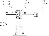
Figure 13 is the profile of D-D section among Figure 11.
Figure 14 is that overlook (being the backsight among Fig. 3) of second slide unit shown in Figure 3 schemed.
Figure 15 is that look up (backsight that is Figure 14) of second slide unit shown in Figure 3 schemed.
Figure 16 is the profile of E-E section among Figure 14.
Figure 17 is that overlook (being the backsight among Fig. 3) of fixed frame shown in Figure 3 schemed.
Figure 18 is that look up (backsight that is Figure 17) of fixed frame shown in Figure 3 schemed.
Figure 19 is the profile of F-F section among Figure 17.
The specific embodiment
See also Fig. 1, shown in Figure 2, frame for mantaining blood sampling needle of the present invention is formed by cylindrical shell 1 with in the front end installation blood taking needle fixture 2 of cylindrical shell 1.Blood taking needle fixture 2 includes two slide units that slide in the front end next door 11 (consulting shown in Figure 6) along cylindrical shell 1; Promptly, first slide unit 22, second slide unit 23, when one side's slide unit (first slide unit 22) slides in the opposing party's slide unit (second slide unit) side, be for can with the positive type coupling apparatus structure combining state of the socket of blood taking needle, in contrast, when the opposing party's slide unit (second slide unit 23) slides in a side slide unit (first slide unit 22) side, be for the positive type coupling apparatus of the socket of blood taking needle can not bonded configuration state.
See also Fig. 3 to shown in Figure 19, describe the concrete structure of frame for mantaining blood sampling needle of the present invention below in detail.
At first see also Fig. 6, shown in Figure 7, the front end of cylindrical shell 1 is with next door 11 sealings, and the rear end is the shape that is opened simultaneously, and next door 11 is provided with the installing hole 15 of through hole 12 and blood taking needle fixture 2.This through hole 12 can make the needle tubing part (rear end side) of the serum cap protection of blood taking needle (not shown) pass through; and that designs is big as far as possible; the needle tubing of 2 li fixed blood taking needles of blood taking needle fixture is partly outstanding to the inside of cylindrical shell 1 by this through hole 12, the rubber bolt of the blood taking tube (not shown) that transfixation is being inserted from the open end of cylindrical shell 1.The installing hole 15 of blood taking needle fixture can insert and fixing fixed frame 24 described later in conjunction with foot 241, the long limit of installing hole 15 is than big in conjunction with the width of foot 241, the minor face of installing hole 15 than in conjunction with the thickness of foot 241 (refer to be called as thickness definitely in conjunction with hook 242 parts of the front end of foot 241, as shown in figure 18) big.Cylindrical shell 1 forms cone shape undergauge shape from the rear end forward end, in order to keep the stable of cylindrical shell 1, is provided with flange 13 in the rear end of cylindrical shell 1, for blood taking needle fixture 2 is installed easily and preferably, is provided with a pair of guiding wall 14 at the front end of cylindrical shell 1.The recess 16 of cylindrical shell 1 front end is the recess that the bottom surface 222 (in conjunction with shown in Figure 13) for the joint portion 221 of the bottom surface 211 of the bonded block 21 that disposes aftermentioned blood taking needle fixture 2 (in conjunction with shown in Figure 10) and first slide unit 22 is provided with, the width of these bottom surface 222 sides is big during combination, and is stepped narrower.
On the front end next door 11 between a pair of guiding wall 14 of above-mentioned cylindrical shell 1, blood taking needle fixture 2 is parallel installation with guiding wall 14.See also Fig. 3 to shown in Figure 5, blood taking needle fixture 2 is made up of bonded block 21, first slide unit 22, second slide unit 23 and 24 4 parts of fixed frame.The mounting structure of the blood taking needle of blood taking needle fixture 2, as Fig. 3 and shown in Figure 5, during its splitting cloudy type coupling apparatus 213,223 and be near state separately, the bonded block 21 and first slide unit 22 can be approaching; As shown in Figure 4, during the separated attitude of the cloudy type coupling apparatus of its splitting separately 213,223, the bonded block 21 and first slide unit 22 are separated, blood taking needle then from blood taking needle then fixture 2 come off.
See also Fig. 3 and shown in Figure 5, four parts of blood taking needle fixture 2 be near state be configured.Promptly, the bonded block 21 and the first slide unit 22 cloudy type coupling apparatus 213,223 of splitting separately constitutes cloudy type coupling apparatus for adjacency or near configuration state, the inside of the end face 246 of fixed frame 24 is provided with the groove 244 of bonded block 21 configuration usefulness and the groove 245 of first slide unit, 22 configuration usefulness, on groove 244 and groove 245, respectively with its surface as the bottom surface, again on fixed frame 24, the surface of second slide unit 23 as the bottom surface, is placed the joint portion 221 of the bonded block 21 and first slide unit 22 advance in the frame 231.On the next door 11 of cylindrical shell 1 front end, with the end face 246 of fixed frame 24 as above, blood taking needle fixture 2 is installed, frame for mantaining blood sampling needle promptly assembles and finishes like this.
Near state, in conjunction with consulting Figure 12, shown in Figure 180, in the groove 225 of the hook 224 of first slide unit 22, being in conjunction with projection 243 of the guide wall 248 of fixed frame 24 embeds its internal state, and first slide unit 22 is relevant with bonded block 21, is the state that can not slide.At this moment, being in conjunction with the inclined plane of decontrol 232 and the inclined plane 226 of the front end of hook 224 of second slide unit 23 (in conjunction with shown in Figure 14) contacts or near state, at this moment, the socket of second slide unit 23 extruding projection 233 is positioned at the outside of the confession socket extruding projection of bonded block 21 by the hole 212 of usefulness.
In isolation, four parts of blood taking needle fixture 2 dispose as shown in Figure 4.That is, the bonded block 21 and first slide unit 22 are isolated state with the cloudy type coupling apparatus of splitting 213,223 respectively, therefore blood taking needle can not be installed.Have again, from the groove 225 of the hook 224 of first slide unit 22, the coming off of the sliding wall 248 of fixed frame 24 in conjunction with projection 243, then first slide unit 22 can slide to bonded block 21 directions.At this moment, second slide unit 23 in conjunction with the front end of decontrol 232 with combine projection 243 in abutting connection with or the position that closely connects, the socket of second slide unit 23 pushes projection 233 and inserts the hole 212 of also passing through usefulness by the socket extruding projection of bonded block 21, is the configuration state of giving prominence to for to the outside of the cloudy type coupling apparatus 213 of splitting of bonded block 21.
See also Fig. 8 to shown in Figure 10, bonded block 21 is provided with the cloudy type coupling apparatus of splitting 213 (in the drawings, it adopts screw thread for screwing device), is installed on the fixed frame 24 motionless.Bottom surface 211 is wideer than top 214 width, is contiguous to toply 214, and is provided with the hole 212 that can pass through for the socket extruding projection 233 of second slide unit 23.During 2 combinations of blood taking needle fixture, on the bottom surface 211 of bonded block 21,, dispose first slide unit 22 (as shown in Figure 5) as loading hook 224.See also Fig. 3 and Figure 11 to shown in Figure 13, first slide unit 22 is provided with the joint portion 221 and the hook 224 of the cloudy type coupling apparatus of splitting 223 (adopting screw thread as screwing device), and its guide wall 248 along fixed frame 24 can be slided.The coupling apparatus that hook 224 is made up of a pair of arm parallel with the outside of joint portion 221, in the outside of this hook 224, be provided with fixed frame 24 combine projection 243 bonded grooves 225, be provided with the inclined plane 226 of undergauge from these groove 225 part forward end.This inclined plane 226 is parallel with the inclined plane in conjunction with decontrol 232 of second slide unit 23, because when being subjected to extruding in conjunction with decontrol 232, hook 224 is crooked to the inside, then can make being separated from groove 225 in conjunction with projection 243 of fixed frame 24.
See also Figure 14 to shown in Figure 16, second slide unit 23 prevents that by including first slide unit 22 is from the come off hole 231, socket extruding projection 233 of part 234 and form in conjunction with decontrol 232 etc. of preventing of coming off of fixed frame 24.Above-mentioned hole 231 is designed on long axis direction, prevents that from this hole 231 the come off opposition face direction of part 234 is outstanding to the inside; Above-mentioned socket extruding projection 233 is by the hole 212 of bonded block 21, the jack of extruding blood taking needle; Above-mentioned is for the combination that combines projection 243 with fixed frame 24 of the hook 224 of removing first slide unit 22 in conjunction with decontrol 232; First slide unit 22 can slide along the sliding wall 248 of fixed frame 24 equally.231 the side outside in the hole is provided with and limits its breach 235 that slides to the long axis direction of second slide unit 23 (two ends of this breach 235 are collided mutually and limited its slip in conjunction with projection 243 to fixed frame 24).
Please in conjunction with consulting Fig. 3, Figure 17 to shown in Figure 19, fixed frame 24 has the function of combination bonded block 21, first slide unit 22, second slide unit 23, have simultaneously and fix above-mentioned functions of components on cylindrical shell 1, fixed frame 24 is formed by through hole 247 with in conjunction with foot 241.Through hole 247 is for than the big hole of cloudy type coupling apparatus that cloudy type coupling apparatus 213,223 is constituted of splitting by the joint portion 221 of the bonded block 21 and first slide unit 22, has on cylindrical shell 1 the fixedly function of blood taking needle fixture 2 in conjunction with foot 241.Extend downwards in conjunction with the guide wall 248 of foot 241, be arranged on the medial wall of guide wall 248, combine with the groove 225 of the hook 224 of first slide unit 22 in conjunction with projection 243 from lead first slide unit 22, second slide unit 23.For fixing fixed frame 24 on cylindrical shell 1, be provided with hook 242 in lower end in conjunction with foot 241, and outstanding laterally.In order to dispose bonded block 21, be provided with recess 244 in the inside of fixed frame 24; In order to dispose first slide unit 22, be provided with recess 245.
In Fig. 3 to Fig. 5, first slide unit, 22, the second slide units 23 are determined from the size of cylindrical shell 1 outstanding (edge bloats), but have only a slide unit to bloat also passable from the edge of cylindrical shell 1.That is, to shown in Figure 13, on first slide unit 22, this joint portion 221 shortens with the lateral partial distance of its opposition as Figure 11, and simultaneously, to shown in Figure 16, on second slide unit 23, the width of the long axis direction of the part 234 that prevents to come off is for short as Figure 14.
Like this, near state only second slide unit 23 can bloat from the edge of cylindrical shell 1, in isolation, only first slide unit 22 can bloat from the edge of cylindrical shell 1.For the blood taking needle of the assembling that comes off on blood taking needle fixture 2, the slide unit (second slide unit 23) that extruding bloats from cylindrical shell 1 edge is for well.
Again, second slide unit 23 can not bloat from cylindrical shell 1 edge yet.Promptly, extremely shown in Figure 13 as Figure 11, on first slide unit 22, this joint portion 221 shortens with the lateral partial distance of its opposition, simultaneously, shown in Figure 14 to 16, on second slide unit 23, the width of the long axis direction of the part 234 that prevents to come off is only short than the situation that an above-mentioned side's slide unit bloats from cylindrical shell 1 edge; Near state, first slide unit 22, second slide unit 23 do not bloat from cylindrical shell 1 edge; In isolation, only first slide unit 22 bloats from cylindrical shell 1 edge.In this case, distinguish first slide unit 22 and second slide unit 23 is difficult, so, coat color for well for second slide unit 23.For the blood taking needle of the assembling on blood taking needle fixture 2 that comes off, it is better to push the slide unit (the second sliding parts 23) of having coated color.If the second sliding part parts 23 have been coated color, so then can prevent from for example to take place when second slide unit 23 makes the accident that skin is pressed in these second slide unit, 23 contacts when skin side is taken a blood sample.
The formation material of blood taking needle fixture 2 is described as follows.Particularly first slide unit 22 and fixed frame 24, hook 224, hook 242 will have the pliability requirement in each parts, the general pliability resin that adopts, for example polyethylene, polypropylene, polyester, ABS resin etc., but the formation material of the bonded block 21 and second slide unit 23 is not particularly limited and will adopts the pliability resin, generally adopts proper metal and other synthetic resin better.
Also have, blood taking needle fixture 2 have more than be limited to for embodiment, also should consider various variant embodiment.Have, the quantity and the shape thereof of parts are described as follows again, and generally contain two slide units, and there is no particular limitation.For example, device in conjunction with the fixed frame 24 and first slide unit 22, and 23 li of second slide units, remove in the bonded device of the fixed frame 24 and first slide unit 22, on fixed frame 24, be provided with groove or hole, combine with the projection that on the hook 224 of first slide unit 22, is provided with, use with embodiment in second slide unit 23 same combine decontrol, can remove combining of fixed frame 24 and hook 224.
See also Fig. 3 to shown in Figure 5, the operating position of frame for mantaining blood sampling needle of the present invention is described.In Fig. 3 and Fig. 5, the cloudy type coupling apparatus 223 of splitting of the joint portion 221 of splitting the cloudy type coupling apparatus 213 and first slide unit 22 of the bonded block 21 of blood taking needle fixture 2 is near state, and the groove 225 of the hook 224 of first slide unit 22 combines in conjunction with projection 243 with fixed frame 24.In this state, first slide unit 22 can not move along long axis direction, constitutes cloudy type coupling apparatus between the cloudy type coupling apparatus 223 of the cloudy type coupling apparatus of splitting 213 of bonded block 21 and the joint portion 221 of first slide unit 22.
2 li blood taking needle is installed in the blood taking needle fixture, after the blood taking needle operation has been finished, push second slide unit 23, slide along the inclined plane 226 of the hook 224 of first slide unit 22 in the inclined plane in conjunction with decontrol 232 of second slide unit 23, so hook 224 is crooked to the inside, from groove 225 break away from fixed frames 24 in conjunction with projection 243.Again, hook 224 is by in conjunction with decontrol 232, to the long axis direction extruding, so first slide unit 22 and bonded block 21 move cloudy type coupling apparatus 213, the 223 separated as shown in Figure 4 attitudes of splitting to detaching direction.At this moment, because blood taking needle is the threaded portion wedging to the cloudy type coupling apparatus of splitting 213 of bonded block 21, and can not break away from, but on second slide unit 23, be provided with socket extruding projection 233, socket extruding projection 233 by the extruding blood taking needle, blood taking needle is broken away from from the threaded portion of the cloudy type coupling apparatus 213 split, and then blood taking needle can more easily come off.
After blood taking needle comes off, push first slide unit 22, because the front end of the hook 224 of first slide unit 22 is provided with inclined plane 226, so that fixed frame 24 crooked laterally in conjunction with foot 241, exceed fixed frame 24 in conjunction with projection 243, this slides into chimeric position in conjunction with projection 243 for 225 li at groove, the cloudy type coupling apparatus of splitting 213,223 is reached as Fig. 3 be near state as shown in Figure 5.
Blood taking needle fixture 2 of the present invention, the blood taking needle of its use is not limited, and can use the medical apparatus of entry needle, for example, can adopt syringe or the like yet.
The present invention compared with prior art has obvious advantage and good effect.
By above clearer and more definite explanation as can be known, use frame for mantaining blood sampling needle of the present invention, can be not and the blood taking needle phase Contact, and easy unloading blood taking needle can prevent because the mistake that use brings when winning blood taking needle after being over The accident of perforating wound and infection. Have again, can use the existing blood taking needle that screws togather pattern, so both economical. Employing screws togather fixedly blood taking needle of formula, can firmly fix blood taking needle, and blood taking needle in use can not come off, And the operation of can taking a blood sample safely.
Claims (5)
1. frame for mantaining blood sampling needle, it is to seal with next door (11) at front end, on the front end next door of rear end for the cylindrical shell (1) of open shape, be provided with the through hole (12) of the needle tubing part that can insert the rubber sheath protection that passes to blood taking needle, simultaneously, combine with the socket of blood taking needle, be provided with the blood taking needle fixture (2) of fixing this blood taking needle, it is characterized in that described blood taking needle fixture (2) is provided with first slide unit (22) of the cloudy type coupling apparatus of splitting (223) that combines with the positive type coupling apparatus of blood taking needle, be provided with the bonded block (21) of the cloudy type coupling apparatus of splitting (213), be provided with second slide unit (23) of the device that prevents that first slide unit from coming off, and be provided with in the front end next door of cylindrical shell and fix first slide unit (22), the fixed frame (24) of second slide unit (23) and bonded block (21) thereof; When first slide unit (22) slides in second slide unit (23) side, constitute cloudy type coupling apparatus between first slide unit and bonded block, simultaneously, first slide unit and fixed frame mutually combine; When second slide unit (23) slided in first slide unit (22) side, this state of mutually combining was disengaged.
2. frame for mantaining blood sampling needle according to claim 1, it is characterized in that described first slide unit (22) and fixed frame (24) are when mutually combining state, second slide unit (23) is outstanding from fixed frame (24), when the state of mutually combining of first slide unit (22) and fixed frame (24) is disengaged, first slide unit (22) is outstanding from fixed frame (24), when first slide unit (22) slides in second slide unit (23) side, be the state of mutually combining, when second slide unit (23) slided to first slide unit (22) side, the state of mutually combining was disengaged.
3. frame for mantaining blood sampling needle according to claim 1, it is characterized in that described second slide unit (23) is provided with the extruding projection (233) of the socket of extruding blood taking needle, simultaneously, on described bonded block (21), be provided with the hole (212) that this projection is passed through.
4. frame for mantaining blood sampling needle according to claim 1, it is characterized in that described first slide unit (22) and fixed frame (24) are when mutually combining state, second slide unit (23) is not outstanding from fixed frame (24), but, when first slide unit (22) is disengaged with mutually combining of fixed frame (24), first slide unit (22) is outstanding from fixed frame (24), when first slide unit (22) slides to second slide unit (23) side, is the state of mutually combining; When second slide unit (23) slided to first slide unit (22) side, the state of mutually combining was disengaged.
5. frame for mantaining blood sampling needle according to claim 1 is characterized in that described second slide unit (23) is coated with color.
Applications Claiming Priority (3)
| Application Number | Priority Date | Filing Date | Title |
|---|---|---|---|
| JP304855/95 | 1995-11-22 | ||
| JP30485595 | 1995-11-22 | ||
| JP304855/1995 | 1995-11-22 |
Publications (2)
| Publication Number | Publication Date |
|---|---|
| CN1154230A CN1154230A (en) | 1997-07-16 |
| CN1130167C true CN1130167C (en) | 2003-12-10 |
Family
ID=17938098
Family Applications (1)
| Application Number | Title | Priority Date | Filing Date |
|---|---|---|---|
| CN96120529A Expired - Fee Related CN1130167C (en) | 1995-11-22 | 1996-11-14 | Frame for mantaining blood sampling needle |
Country Status (9)
| Country | Link |
|---|---|
| US (2) | US5797490A (en) |
| EP (1) | EP0780136B1 (en) |
| JP (1) | JP2723105B2 (en) |
| KR (1) | KR100281243B1 (en) |
| CN (1) | CN1130167C (en) |
| AT (1) | ATE203918T1 (en) |
| DE (1) | DE69614352T2 (en) |
| HK (1) | HK1000499A1 (en) |
| TW (1) | TW355138B (en) |
Families Citing this family (33)
| Publication number | Priority date | Publication date | Assignee | Title |
|---|---|---|---|---|
| US5616136A (en) | 1995-01-09 | 1997-04-01 | Med-Safe Systems, Inc. | Quick release needle removal apparatus |
| JP3531149B2 (en) * | 1996-07-31 | 2004-05-24 | ニプロ株式会社 | Blood collection needle waste container |
| JPH11155839A (en) * | 1997-12-02 | 1999-06-15 | Takaharu Suzuki | Vacuum blood-collecting holder |
| US6306118B1 (en) * | 1998-03-13 | 2001-10-23 | Becton, Dickinson And Company | Needle holder assembly |
| AT413328B (en) * | 1998-12-23 | 2006-02-15 | Greiner Bio One Gmbh | Reception unit for body fluid or tissue sampling needle insert has retaining device released via actuator provided by one-piece sliding plate with slot locating retaining device having retaining and release elements |
| AT407007B (en) | 1998-12-23 | 2000-11-27 | Greiner Labortechnik Gmbh | RECEIVING DEVICE FOR AN INSERT ELEMENT |
| US6132402A (en) * | 1999-02-02 | 2000-10-17 | Bioform Inc. | Storage and delivery device for a catheter or needle |
| USD433505S (en) * | 1999-03-10 | 2000-11-07 | Becton Dickinson And Company | Needle holder |
| US6511440B2 (en) * | 2001-01-22 | 2003-01-28 | Long Hsiung Chen | Safety vacuum syringe for blood sampling conformed to ergonomics |
| CA2456969A1 (en) * | 2001-08-09 | 2003-02-27 | Becton, Dickinson And Company | Retracting needle safety device |
| US6994213B2 (en) * | 2001-09-18 | 2006-02-07 | Becton, Dickinson And Company | Packaging for push button blood collection set |
| US7294118B2 (en) * | 2001-10-24 | 2007-11-13 | Becton, Dickinson And Company | Retractable needle assembly |
| US7258678B2 (en) * | 2002-03-14 | 2007-08-21 | Becton, Dickinson And Company | Retractable safety needle |
| JP4257943B2 (en) * | 2002-07-29 | 2009-04-30 | アークレイ株式会社 | Puncture unit and puncture member removal tool |
| US6991608B2 (en) * | 2003-04-03 | 2006-01-31 | Becton, Dickinson And Company | Medical assembly |
| US6994694B2 (en) * | 2003-08-19 | 2006-02-07 | Saftey 1St Medical, Inc. | Apparatus for retaining concentric parts within one another |
| DE10348603A1 (en) * | 2003-10-20 | 2005-05-19 | Klinika Medical Gmbh | Cannula holder comprises an unlocking mechanism which is constituted so that after its operation the cannula and/or the adapter will fall into the cannula container |
| US20060195062A1 (en) * | 2005-02-25 | 2006-08-31 | Gremel Robert F | Apparatus for locking concentric components in alignment |
| EP1871271B1 (en) | 2005-04-22 | 2018-04-11 | Becton, Dickinson and Company | Prepackaged medical device and method |
| US7396342B2 (en) * | 2005-11-25 | 2008-07-08 | Biotop Holding Co., Ltd. | Safety syringe for taking blood |
| US20070123822A1 (en) * | 2005-11-25 | 2007-05-31 | Biotop Holding Co., Ltd. | Safety syringe for taking blood |
| US20080009806A1 (en) * | 2006-07-10 | 2008-01-10 | Biotop Holding Co., Ltd. | Blood sampling device |
| DE102007002096A1 (en) * | 2007-01-09 | 2008-07-10 | B. Braun Melsungen Ag | Device for injecting liquids |
| US20100286558A1 (en) * | 2009-04-08 | 2010-11-11 | Stat Medical Devices, Inc. | Fluid collection/injection device having quick release/removable double-ended needle and safety system |
| US8269972B2 (en) | 2010-06-29 | 2012-09-18 | Honeywell International Inc. | Beam intensity detection in a cavity ring down sensor |
| US8437000B2 (en) | 2010-06-29 | 2013-05-07 | Honeywell International Inc. | Multiple wavelength cavity ring down gas sensor |
| US8322191B2 (en) | 2010-06-30 | 2012-12-04 | Honeywell International Inc. | Enhanced cavity for a photoacoustic gas sensor |
| US10092230B2 (en) * | 2011-04-29 | 2018-10-09 | Stat Medical Devices, Inc. | Fluid collection/injection device having safety needle assembly/cover and safety system and method |
| US9078978B2 (en) | 2011-12-28 | 2015-07-14 | Stat Medical Devices, Inc. | Needle assembly with safety system for a syringe or fluid sampling device and method of making and using the same |
| GB201304717D0 (en) * | 2013-03-15 | 2013-05-01 | Imerys Minerals Ltd | Paper composition |
| US20210106262A1 (en) * | 2017-03-01 | 2021-04-15 | Fenwal, Inc. | Sample Tube Holder And System And Method Employing Same |
| CN108968981A (en) * | 2018-06-22 | 2018-12-11 | 刘重斌 | A kind of vacuum blood collection tube |
| CN109893141B (en) * | 2019-03-15 | 2021-08-20 | 中国人民解放军陆军军医大学第二附属医院 | Fixing device for blood sampling |
Citations (6)
| Publication number | Priority date | Publication date | Assignee | Title |
|---|---|---|---|---|
| JPS62148646A (en) * | 1985-12-21 | 1987-07-02 | 株式会社 ニッショー | Blood sampling needle holder |
| WO1989005118A1 (en) * | 1987-12-07 | 1989-06-15 | Arild Jensen | A device for taking blood samples |
| US4942881A (en) * | 1988-04-26 | 1990-07-24 | Al Sioufi Habib | IV needle holder |
| JPH02297342A (en) * | 1988-09-28 | 1990-12-07 | Terumo Corp | Blood drawing and/or injection device using both cutter needle-shaped medical needle and holder, and the same medical needle and holder |
| CN2104641U (en) * | 1991-09-20 | 1992-05-20 | 刘立昌 | Hemospats |
| CN2181260Y (en) * | 1993-11-04 | 1994-11-02 | 济南龙冠电子技术发展有限公司 | Disposable vacuum hemostix |
Family Cites Families (10)
| Publication number | Priority date | Publication date | Assignee | Title |
|---|---|---|---|---|
| FR1592765A (en) * | 1968-11-21 | 1970-05-19 | ||
| JPS6428589A (en) | 1987-07-24 | 1989-01-31 | Toshiba Corp | Bottom construction of containment vessel |
| US4892107A (en) * | 1988-01-05 | 1990-01-09 | Habley Medical Technology Corp. | Single use, safety blood collection device |
| US4951685A (en) * | 1988-05-12 | 1990-08-28 | Blair Paul A | Blood drawing system |
| US5020665A (en) * | 1988-07-01 | 1991-06-04 | John Bruno | Storage/carrying devices for transport of hypodermic needle/syringe assemblies to bedside use and ultimate disposal |
| JPH0373134A (en) * | 1989-05-19 | 1991-03-28 | Terumo Corp | Liquid collecting tube stand with holder holding jig |
| US5125414A (en) * | 1990-01-16 | 1992-06-30 | Dysarz Edward D | Trap in barrel one handed retracted blood sampling device |
| US5401250A (en) * | 1992-10-05 | 1995-03-28 | Shields; Jack W. | Tethered conical shield for phlebotomy needles |
| US5509319A (en) * | 1994-06-21 | 1996-04-23 | Geo-Microbial Technologies, Inc. | Adapter for pipetter and hypodermic needle |
| US5685855A (en) * | 1996-07-23 | 1997-11-11 | Erskine; Timothy J. | Protected needle catheter placement device with sampling provisions and method for its use |
-
1996
- 1996-06-17 JP JP8155271A patent/JP2723105B2/en not_active Expired - Fee Related
- 1996-10-09 US US08/728,146 patent/US5797490A/en not_active Expired - Lifetime
- 1996-10-23 AT AT96117000T patent/ATE203918T1/en not_active IP Right Cessation
- 1996-10-23 EP EP96117000A patent/EP0780136B1/en not_active Expired - Lifetime
- 1996-10-23 DE DE69614352T patent/DE69614352T2/en not_active Expired - Lifetime
- 1996-10-30 TW TW085113246A patent/TW355138B/en not_active IP Right Cessation
- 1996-11-14 CN CN96120529A patent/CN1130167C/en not_active Expired - Fee Related
- 1996-11-19 KR KR1019960055326A patent/KR100281243B1/en not_active IP Right Cessation
-
1997
- 1997-10-17 HK HK97101947A patent/HK1000499A1/en not_active IP Right Cessation
-
1998
- 1998-03-23 US US09/045,714 patent/US5961473A/en not_active Expired - Lifetime
Patent Citations (6)
| Publication number | Priority date | Publication date | Assignee | Title |
|---|---|---|---|---|
| JPS62148646A (en) * | 1985-12-21 | 1987-07-02 | 株式会社 ニッショー | Blood sampling needle holder |
| WO1989005118A1 (en) * | 1987-12-07 | 1989-06-15 | Arild Jensen | A device for taking blood samples |
| US4942881A (en) * | 1988-04-26 | 1990-07-24 | Al Sioufi Habib | IV needle holder |
| JPH02297342A (en) * | 1988-09-28 | 1990-12-07 | Terumo Corp | Blood drawing and/or injection device using both cutter needle-shaped medical needle and holder, and the same medical needle and holder |
| CN2104641U (en) * | 1991-09-20 | 1992-05-20 | 刘立昌 | Hemospats |
| CN2181260Y (en) * | 1993-11-04 | 1994-11-02 | 济南龙冠电子技术发展有限公司 | Disposable vacuum hemostix |
Also Published As
| Publication number | Publication date |
|---|---|
| US5797490A (en) | 1998-08-25 |
| CN1154230A (en) | 1997-07-16 |
| KR970025563A (en) | 1997-06-24 |
| EP0780136A2 (en) | 1997-06-25 |
| EP0780136B1 (en) | 2001-08-08 |
| JPH09201349A (en) | 1997-08-05 |
| ATE203918T1 (en) | 2001-08-15 |
| EP0780136A3 (en) | 1997-07-16 |
| KR100281243B1 (en) | 2001-02-01 |
| HK1000499A1 (en) | 2002-05-10 |
| DE69614352D1 (en) | 2001-09-13 |
| TW355138B (en) | 1999-04-01 |
| US5961473A (en) | 1999-10-05 |
| JP2723105B2 (en) | 1998-03-09 |
| DE69614352T2 (en) | 2001-11-22 |
Similar Documents
| Publication | Publication Date | Title |
|---|---|---|
| CN1130167C (en) | Frame for mantaining blood sampling needle | |
| CN1311591C (en) | Electric connector with locking mechanism | |
| CN1297327C (en) | Connector with blunt nosed intubate lock | |
| EP0816976B1 (en) | PCI expansion card retainer clip | |
| US7690233B2 (en) | Portable device and mechanical key | |
| CN1764014A (en) | The socket that is used for trans-flash memory card | |
| WO2017179813A1 (en) | Syringe-coupled safety assembly and safety syringe including same | |
| CN1197878A (en) | Lock for sliding closure | |
| CN1497191A (en) | Single-touch lead end used for controlling cable fixation | |
| CN1815898A (en) | Battery pack locking apparatus for mobile terminal | |
| CN1968862A (en) | Clamp for closing a flexible bag | |
| CN202305893U (en) | Optical fiber connector plug | |
| CN214081133U (en) | Automatic locking of sensor is gone into shell installation location frock | |
| CN1555594A (en) | Nut holding structure for connector | |
| CN1645677A (en) | Connector | |
| CN211622952U (en) | Key with a key body | |
| CN1750416A (en) | Battery unit locking device of mobile communication terminal | |
| CN218739735U (en) | Injection pump | |
| WO2009136687A1 (en) | Safety syringe | |
| CN219645949U (en) | Auxiliary device for intravenous injection of tail of mouse | |
| CN1627769A (en) | Cell latch of portable terminal | |
| CN2650706Y (en) | Blood sampler with telescopic fastened needle | |
| CN212244396U (en) | Bone marrow slide glass storage box | |
| EP0692854A1 (en) | Vandal resistant elevator component | |
| CN212459725U (en) | Multifunctional food safety detector |
Legal Events
| Date | Code | Title | Description |
|---|---|---|---|
| C06 | Publication | ||
| PB01 | Publication | ||
| C10 | Entry into substantive examination | ||
| SE01 | Entry into force of request for substantive examination | ||
| C14 | Grant of patent or utility model | ||
| GR01 | Patent grant | ||
| C17 | Cessation of patent right | ||
| CF01 | Termination of patent right due to non-payment of annual fee |
Granted publication date: 20031210 Termination date: 20131114 |