CN1154525C - Regulator with artificial load to maintain regulated delivery drug - Google Patents
Regulator with artificial load to maintain regulated delivery drug Download PDFInfo
- Publication number
- CN1154525C CN1154525C CNB988122677A CN98812267A CN1154525C CN 1154525 C CN1154525 C CN 1154525C CN B988122677 A CNB988122677 A CN B988122677A CN 98812267 A CN98812267 A CN 98812267A CN 1154525 C CN1154525 C CN 1154525C
- Authority
- CN
- China
- Prior art keywords
- controller
- voltage
- actuator
- inducer
- switch
- Prior art date
- Legal status (The legal status is an assumption and is not a legal conclusion. Google has not performed a legal analysis and makes no representation as to the accuracy of the status listed.)
- Expired - Fee Related
Links
Images


Classifications
-
- A—HUMAN NECESSITIES
- A61—MEDICAL OR VETERINARY SCIENCE; HYGIENE
- A61N—ELECTROTHERAPY; MAGNETOTHERAPY; RADIATION THERAPY; ULTRASOUND THERAPY
- A61N1/00—Electrotherapy; Circuits therefor
- A61N1/18—Applying electric currents by contact electrodes
- A61N1/20—Applying electric currents by contact electrodes continuous direct currents
- A61N1/30—Apparatus for iontophoresis, i.e. transfer of media in ionic state by an electromotoric force into the body, or cataphoresis
Abstract
An electrotransport device with a drug delivery regulating apparatus delivers a proper drug dosage rate over time by adapting to variable skin resistance values. The electrotransport device adapts to a decline in skin resistance over a time that the electrotransport device is used, and to different skin resistances at different skin surface locations. One drug delivery regulating apparatus includes a voltage booster, a serially connectable artificial impedance, and a feedback sensor, which are all connected to a controller. The controller monitors the output of the feedback sensor to determine the skin resistance, or a load current, or the load voltage so that a targeted drug dose rate is maintained.
Description
Technical field
The present invention relates generally to patient is provided through subcutaneous or through mucous membrane the electric transmission device of beneficial agent (as medicament).Particularly, the present invention relates to a kind of portable or electronic conveying feedway that patient wears, described device has booster and dummy load to keep stably supplying with beneficial agent.
Background technology
Terminology used here " electronic conveying " generally is meant by certain thin film (such as skin, mucosa) or fingernail (nail) supplies with reagent (as medicament), wherein is supplied to the small part land productivity and introduces with current potential.For example, do electronic conveying, useful therapeutic agent can be introduced the systemic circulation of animal (as the mankind) by skin.
Have been found that electronic transport process helps through subcutaneous administration, comprises lidocaine hydrochloric acid hydrochloride, hydrocortisone, fluoride, penicillin, dexamethasone sodium phosphate and many other medicines.Perhaps the most frequently used electronic conveying is by providing ionophoresis Pilocarpus jaborandi alkali salt to diagnose the cyst fibrosis.Pilocarpine can promote to perspire, and antiperspirant is collected analyze its chloride content then, with detection disease is arranged.
Know that now electric transmission device uses two electrodes at least, electrode contacts closely with some part (as skin) of animal body.First electrode is called active electrode or supplies with electrode, utilizes electronic conveying that therapeutic agent (as medicament or auxiliary medicine agent) is sent in the body.Second electrode is called counter electrode or refurn electrode, by the circuit of animal body connection with first electrode.Electric energy such as battery one class provides electric current by these electrodes to animal body.For example, if prepare the therapeutic agent positively charged (being cation) of input animal body, anode will be an active electrode so, and negative electrode will be as counter electrode and forming circuit.If the therapeutic agent electronegative (being anion) that preparation provides, then negative electrode will be to supply with electrode, and anode will be a counter electrode.
Perhaps, anode and negative electrode all can be used to the medicament of opposite charges is imported in the body.In the case, these two kinds of electrodes all are considered to supply with electrode and counter electrode.For example, anode can provide simultaneously cation therapeutic agent and phase antikathode as " to " electrode.Similarly, negative electrode can simultaneously anionic therapeutic agent be imported in the body and the phase antianode as " to " electrode.
Widely used electronic transport process, i.e. electromigration (being also referred to as ionophoresis), the electric induction that relates to charged ion is carried.Another kind of electronic conveying, i.e. electro-osmosis relates to and is applying under the electric field influence from supply container flowing liquid solvent, and the reagent that will provide is provided this liquid.
Also having the electronic transport process of a class is electroporation, relates to the applying high voltage pulse forms instantaneous existence in biofilm hole.Therapeutic agent can partly utilize the passive skin that diffuses through to provide, because have concentration difference between the drug level in drug level in the supply container of electric transmission device and the patient body inner tissue.In any given electronic course of conveying, more than one this class process can appear to a certain extent simultaneously.Therefore, the most generalized explanation will be given in Yun Yong " electronic conveying " this term here, so it comprises for example electric induction or at least a therapeutic agent of electricity enhancing conveying, no matter it is charged, uncharged or hybrid-type.In addition, the electric current of load current and circulation skin all is defined as mobile electrode between two electrodes.
Electric transmission device requires the container or the source of reagent or this class reagent precursor usually, promptly sends into intravital reagent by electronic conveying.The preferably ionizing or ionizable of the example in this class container or source, reagent comprise the preformed gelinite (United States Patent (USP) 4,383,529) as the satchel (United States Patent (USP) 4,250,878) of Jacobsen description or Webster announcement.This class container is electrically connected to the male or female of electric transmission device, so that the fixing or renewable source of one or more required treatment samples to be provided.
In recent years, issued many United States Patent (USP)s, illustrated that this administering mode continues to attract people's attention in electronic transportation art.For example, people's such as Vernon United States Patent (USP) 3,991,775, people's such as Jacobsen United States Patent (USP) 4,141,359, the United States Patent (USP) 4 of Wilson, 398,545, the United States Patent (USP) 4,250 of Jacobsen, 878, people's such as people's such as Sovenson United States Patent (USP) 5,207,752, Lattin United States Patent (USP) 5,213,568 and the United States Patent (USP) 5,498 of Flower, 235, all disclosed electric transmission device and some examples of applications thereof.
The closer time, particularly along with the development of microminiature circuit (as integrated circuit) and more effective light weight battery (as lithium battery), it is smaller and more exquisite that electric transmission device becomes.Owing to cheap subminiature electronic circuit and dense high-energy battery have occurred; this means whole device can be made little be enough to wear on patient's skin not conspicuously and clothes below; even during the electric transmission device administration, also can allow patient at will walk about and participate in all daily routines like this.
Yet the existing shortcoming of the electric transmission device of original technology has limited these valuable devices and has used widely.One of restriction is to be difficult to regulate dosage.Correctly the complexity of Shu Songing is such fact, and promptly during electronic conveying, the resistance of patient's body surface (as skin) is not constant.Since by patient's skin hold up required voltage (V) direct proportion of the electric current (I) that drives particular level in the resistance (R) of skin (promptly according to Ohm's law, V=IR wherein
Skin, wherein, skin represents skin), so during electronic conveying, it also is inconstant that power source voltage is required.For example, when the electronic conveying administration of beginning, patient's initial skin resistance is higher relatively, requires power supply to produce the electronic conveying electric current that higher voltage provides predetermined level.Yet after a few minutes (after promptly applying the about 1-30 of electric current minute by skin), skin resistance has just dropped, thereby required voltage when providing the required voltage of particular level electric current just to be far smaller than electronic conveying administration to begin.
Regulate electronic another complicated factor that flows to medicine device and be,, aspect thickness, mechanical strength, flexibility and topmost skin resistance, many partial variations are arranged though the structure of the skin of whole human body is substantially the same.
Original technology through the subcutaneous electronic medicine device that flows to, no matter the resistance of skin how, provides the voltage of setting to any skin surface all indiscriminately.In addition, some original technology through subcutaneous electronic flowing in the medicine device, all select the multiple that boosts of supply voltage and/or booster circuit to such an extent that must be enough to overcome the high skin resistance that occurs when beginning to operate greatly.Yet in case operation has reached steady statue, along with the drop of skin resistance, the running voltage of the device of original technology is just too high.Therefore, in case skin holds up resistance to drop down from its initial high resistance, be higher than required voltage owing to provide, so these original technique devices can provide than the more pharmaceutical quantities of the amount of needs.
Therefore, requiring has a kind of improved electric transmission device and method,, can keep a kind of target medicine-feeding rate, and can provide the target medicine-feeding rate to the different skin zone with different resistance during from its initial value drop at skin resistance.
Summary of the invention
One embodiment of the present of invention are a kind of electric transmission devices that bring the medicine conditioning equipment, described conditioning equipment is by adapting to variable skin resistance value, particularly adapt to the situation that skin resistance descends in time when using electric transmission device, and adapt to the different skin resistance in skin factor of different position, proper drug amount speed can be provided in time.
In another embodiment, the administration conditioning equipment comprises booster, series connected emulation impedance and feedback transducer, and they all are connected to controller.This equipment is exported a load voltage between two electrodes.Controller monitors the output of feedback transducer, to determine (a) skin resistance, or (b) load current, or (c) load voltage, and based on the load voltage at the value control electrode two ends that monitor, even thereby initial skin resistance has dropped during using electric transmission device, also can keep target agent amount speed.The emulation impedance that produces is used for falling at skin resistance and prevents overtreatment when being lower than device battery voltage.
Electronic conveying of the present invention utilizes power supply that load voltage and load current are provided between first and second electrode assemblie through subcutaneous administration agent actuator, carries useful medicament by animal skin surfaces, it is characterized in that described actuator comprises:
Controller;
Be electrically connected to the booster of described controller, described power supply and described first electrode assemblie;
Be electrically connected to the control trigger of described second electrode assemblie;
Be connected to described controller and can be connected to second electrode assemblie or the control activator switch of control trigger, described control activator switch is controlled by controller; And
Be connected to the pick off of described controller and control activator switch, wherein, described controller is determined the value of feedback from described pick off, and utilizes described booster, described control trigger, described control activator switch and described value of feedback regulating load voltage.
Description of drawings
Fig. 1 is the electronic perspective view that flows to medicine device of the present invention.
Fig. 2 is the expanded view of electric transmission device of the present invention.
Fig. 3 represents the figure that patient skin resistance descends in time.
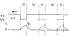
Electric current-the time graph of the load current that the exemplary expression of Fig. 4 electric transmission device of the present invention provides.This figure is a routine electric current-time plot.
Fig. 5 is the time-contour map of the load voltage of electric transmission device of the present invention.
Fig. 6 is the schematic block diagram of administration actuator of the present invention.
Fig. 7 is the signal logical circuitry of administration actuator of the present invention.
Fig. 8 is the sequential chart of Fig. 7 circuit working.
Fig. 9 is the signal logical circuitry of another administration actuator of the present invention.
Figure 10 is the sequential chart of Fig. 9 circuit working.
Figure 11 comprises the electronic perspective view that flows to medicine device that can handle drug unit arbitrarily.
Figure 12 is the expanded view of Figure 11 electric transmission device.
Figure 13 is the signal logical circuitry of another administration actuator of the present invention.
The specific embodiment
Fig. 1-2 and 11-12 show the electronic embodiment that flows to medicine device, and this class device has comprised electronic conveying administration actuator of the present invention.
The electronic perspective view that flows to medicine device 10 shown in Fig. 1, anastomosing optional light emitting diode (LED) 14 when having the optional starting switch of press button 12 forms and installing 10 work.
Fig. 2 is the expanded view of second device 10 of the present invention.On the position of LED14, the device 10 of Fig. 2 is different from the device 10 of Fig. 1.Fig. 2 device 10 comprises cover 16, circuit board assemblies 18, covers 20 down, anode 22, negative electrode 24, the bonding die 30 of male receptacle 26, cathode container 28 and suitable skin.Last cover 16 has the horizontal wing 15, helps Fig. 2 device 10 is remained on the patient skin.Last cover 16 can use injection mould elastomer (as the ethylene vinyl acetate) to form, and also available mark glue or other elastomeric material are formed.Printed circuit-board assembly 18 comprises and discrete component 40 and battery 32 coupled integrated circuits 19.The binding post (not shown among Fig. 2) that circuit board assemblies 18 usefulness are passed opening 13a and 13b is fixed to cover 16, and the binding post two ends are heated/melt, so that cover 16 is supportted in circuit board assemblies 18 heating.Under cover 20 usefulness bonding dies 30 and be fixed to cover 16, the upper surface 34 of bonding die 30 is adhered to down and covers 20 and last cover 16, comprises the bottom surface of the wing 15.
What circuit board assemblies 18 bottoms did not show (part) is button cell 32.The battery of other type also can be applicable to supply unit 10.Device 10 generally comprise battery 32, electronic circuit 19 and 40, electrode 22 and 24 and medicament/chemical agent melt device 26 and 28, all these is integrated into an independently unit.Utilization conduction adhesive tape 42,42 ', opening 23,23 by being formed at down cover 20 center dants 25,25 ' interior ', the outfan (not shown among Fig. 2) of circuit board assemblies 18 and electrode 24 and 22 formation are electrically contacted, and electrode 22 with 24 with medicine container 26 and 28 top margin 44 ', 44 direct mechanical contact with electric.The base 46 of medicine container 26,28 ', 46 by bonding die 30 openings 29 ', 29 and patient's contact skin.
Under cover 20 and can form by plastics or elastomer sheet (as polyethylene), this sheet material hold write molded formation recess 25,25 ' and form opening 23,23 '.The device 10 of assembling preferably can anti-water (being anti-spraying), preferably can waterproof.The section of this system is very thin, is convenient to adapt to human body, can wear the free activity in place.Container 26 and 28 is contained on the skin contact of device 10 and fully separates, in case electric short circuit occurs in carrying with when using.
Any reagent all can use, as long as it is the partial ionization thing at least.The two is general for term " medicament ", and they have the most generalized explanation, promptly is to supply with lived tissue to produce any therapeutic active substance of the normally beneficial effect of wishing.For example, term " medicament " and " reagent " comprise the treatment chemical compound and the molecule of all treatment classifications, comprising (but being not limited to): infection (as antibiotics and antiviral), analgesic is (as fentanyl, sufentanil, buprenorphine and analgesic compositions), anesthetis, antiarthritic, antiasthmatic (as terbutaline), anticonvulsant, antidepressants, antidiabetic drug, the diarrhea medicine, antihistaminic, anti-inflammatory agent, antimigraine, resisting kinetic vomiting preparation (as scopolamine and ondansetron), anticarcinogen, Mirapexin, the anti-medicine of scratching where it itches, psychosis, antipyretic, spasmolytic (comprising gastrointestinal tract and urethra), anticholinergic, sympatheticomimetic, xanthine and its derivant, cardiovascular preparation (comprises the calcium channel blocker as nifedipine, beta-2-agonists (as dobutamine and ritodrine), beta-Blocking agent, antiarrhythmics, antihypertensive (as atenolol), ACE inhibitor (as lisinopril), diuretic, vasodilation (comprises total blood vessel, coronary vasodilator, the blood vessel of peripheral blood vessel and brain), central nervous system's stimulant, cough and cold-treating preparation, decongestant, diagnostic agent, hormone (as parathryoid hormone), hypnotic, immunosuppressant, muscle relaxant, the parasympathetic blocker, intend the parasympathetic agent, prostaglandin, protein, peptide, psychostimulant, analgesic and tranquilizer.
Fax of the present invention send transferable medicine of device and/or reagent to comprise baclofen, beclometasone, betamethasone, buspirone, sodium cromoglicate, diltiazem, doxazosin, droperidol, encainide, fentanyl, tixocortol, indomethacin, ketoprofen, lignocaine, methotrexate, metoclopramide, miconazole, midazolam, nicardipine, piroxicam, prazosin, scopolamine, sufentanil, terbutaline, testosterone, tetracaine and verapamil.
Electric transmission device of the present invention also can provide peptide, polypeptide, protein and other macromole.This quasi-molecule is because its size is big, and being difficult to provides through subcutaneous or through mucous membrane, and this point is being well-known in the art.For example, the molecular wt of this quasi-molecule can be in 3000-40000 dalton scope, and include, but is not limited to: LHRH and homologue thereof are (as buserelin, goserelin, gonadorelin, naphrelin and leuprolide), GHRH, GHRF, insulin, pancreotropic hormone, heparin, calcitonin, octreotide, TRH, NT-36 or N-[[(s)-4-oxygen base-2-azetidinyl] carbonyl]-group acylamino--L-prolineamide], liprecin, pituitary hormone is (as HGH, HMG, HCG, the acetic acid Desmopressin), short follicle luteoid (follicile luteoids), a-ANF, the growth factor release factor (GFRF), b-MSH, somatostatin, Kallidin I, growth hormone derives from from hematoblastic somatomedin, asparaginase, Bleomycin Sulphate, chymopapain, cholecystokinin, army are urged the property element, CRH ELISA (ACTH), erythropoietin, epoprostenol (platelet aggregation inhibitor), glucagon, hirulog, hyaluronidase, interferon, interleukin-2, follicle stimulating hormone (as urinary follicle stimulating hormone (FSH) and LH), oxytocin, streptokinase, the former activator of tissue plasminogen, urokinase, vasopressin, Desmopressin, the ACTH analog, ANP, ANP cleans up inhibitor, angiotension II antagonists, the vassopressin agonist, the vassopressin antagonist, brad ykinin antagonists, CD4, ceredase, CSF ' s, endorphins, FAB fragment, the IgE inhibitor peptides, IGF-1, neurotrophic factor, the bacterium colony simulation factor, inclined to one side thyroxin and agonist, inclined to one side thyroxin antagonist, prostaglandin antagonists, pentigetide, protein C, protein S, blood vessel tension peptide protoenzyme inhibitor, thymosin alpha 1 antitrypsin (recombinant) and TGF-β.
It is to allow patient by electronic conveying oneself control pharmaceutical quantities that device 10 has characteristics.One presses the button switch 12, and the electronic circuit on the circuit board assemblies 18 provides predetermined DC current with regard to counter electrode/ container 22,26 and 24,28 dosing intervals by predetermined length.Press button 12 is positioned on the end face of device 10, is convenient to drive by clothes.At short notice (as 3 seconds) press secondary press button 12, just can drive this device administration, thereby the probability of accidental driving device 10 is reduced to minimum.By LED14 take place and/or for example " sender unit " send resulting acoustical signal, device can begin the visual and/or earcon in administration cycle to the user transmitting acknowledgement.In the predetermined administration cycle, electronic conveying is for example at arm and percutaneous drug delivery by patient.
To install 10 with the bonding die 30 of periphery and paste on the patient body surface (as skin), bonding die 30 has upper surface 34 and people's contact level 36.Bonding die face 36 has adhesiveness, and assurance device 10 remains on the human body in place during the user daily routines, and takes off easily later in predetermined wear the phase (as 24 hours).Bonding die upper surface 34 pastes down cover 20, makes down cover 20 keep being connected to cover 16.
Like this, polypeptide homologue of the present invention can be attached in the medicine container, for example above-mentioned gel-type vehicle, and use above-mentioned exemplary electronic conveying drug-supplying system to disease from administration.The adapted of medicinal liquid can be realized with multiple mode, is about to medicinal liquid and sucks container substrate, rises at water and before glue forms medicinal liquid is sneaked into host material.
Figure 11-12 shows the electronic medicine device that flows to of another embodiment of the present invention.This embodiment comprises the electronic controller and the medicine unit that can reuse.The controller that can reuse among Figure 11-12 is equipped with an administration actuator usually, and is designed to be used in combination with medicine unit, to be stored in the medicament in the medicine unit through subcutaneous supply.
Figure 11 is the perspective view of electric transmission device 320, and its electronic controller that can reuse 322 is suitable for containing 324 coupling and the uncouplings of medicament unit.This controller 322 can reuse, and promptly it is suitable for a plurality of medicine unit 324 of adapted, for example a series of similar and/or extremely different medicine unit 324.On the other hand, medicine unit generally has more limited service life, is suitable for after use, abandons after promptly medicament inside uses up.Like this, after the medicament of 324 li of medicine unit uses up afterwards, can will withdraw from medicine unit 324 slave controllers 322, change the identical or different new medicine unit 324 of structure and/or component at predetermined operation lifetime (as 24 hours).Controller 322 is designed to provide a kind of in the multiple different predetermined electric output, and these electric outputs can be set when manufacture controller.Controller 322 different electric outputs are designed to be used in different medicine unit 324.
As a kind of example, can be designed to the medicine unit different 324 adapteds to the electronic controller that can reuse (calling controller in the following text) 322, and these two kinds of unit all are suitable for same controller 322 adapteds, successive administration in 12 hours with at least two kinds.Two kinds of different medicine unit 324 are equipped with a kind of medicament in its supply container separately, but the pharmaceutical quantities difference.The medicine unit 324 that contains big dose is " heavy dose " unit, is suitable for D.C. high-current (as the 2mA) adapted with controller 322 outputs.The medicine unit 324 that contains less dose is " low dose " unit, is suitable for cooperating with the DC low current (as 1mA) of controller 322 outputs.Like this, controller 322 can be designed to basis coupled with it is low dose or heavy dose of unit 324, and a kind of electric current in two kinds of different DC currents (being 1mA or 2mA) is provided.
The present invention sends signal to controller 322, and showing coupled with it is which kind of medicine unit (as heavy dose of or low dose of unit), so as suitably the output (being the output of big electric current or little electric current) of controller to be provided with coupled medicine unit coupling.In the device in Figure 11 and 12, medicine unit 324 is sent an optical signal to controller 322, shows that controller 322 should send and read then (i.e. decoding) any optical signal automatically according to medicine unit 324 coupled with it (promptly utilizing hasp adapter 326,328).Behind the read output signal, controller reasonably selects correct electricity output to impose on coupled medicine unit 324.
With reference to Figure 12, be illustrated as the expanded view of medicine unit 324 and controller 322.Controller 322 comprises cover 368 and covers 350 down that the two is formed by molded plasticss such as polyethylene usually.Last cover 368 is connected to down cover 350 by the anti-spraying and the waterproof peripheral seal member of adjacency.Cover is bonded on their points of common connection with the waterproof stick, the junction point between cover 350,368 has just been realized sealing by heated sealant or ultra-sonic welded.Cover 350 down an opening 352 of admitting battery 354 is arranged.Each plate of battery contact point 364,366 that is equipped with and battery 354 keeps electrically contacting.Dismountable type cover cap 360 usefulness screws are screwed into opening 352 makes battery 354 in place.Cover cap 360 has a groove 362, can insert coin or bottle opener and rotate cover cap 360 and it is taken out from opening 352, so that pick and place (promptly changing) battery 354.Controller 322 comprises a battery 354, as button cell, the circuit (not shown) on the circuit board 359 is powered.Circuit board 359 forms with conventional method, has the conductive traces pattern of interconnection electrical equipment thereon, is used to control the amplitude, sequential, frequency, waveform shape of controller 322 electric outputs (as voltage and/or electric current) etc.Can use the conductive traces on conventional silk-screen printing technique or scolder coating copper plating mask and the etch process deposit circuit board 359.The making such as FR-4 of the insulating base available standards of circuit board 359.Although be not very strict for purposes of the invention, but controller 322 comprises the press button 374 and a liquid crystal display 356 (Figure 11) that can only be used for launcher 310 work, display 356 can pass through window 358 (Figure 12) display system information, answers exhausted time, battery strength or the like such as the particular type of the medicine unit 324 that is coupled to controller, the current level that applies, dosage level, the number of times that dosage is provided, electric current.
Cover 350 down and be furnished with hole 375a, the 375b that keeps electrically conductive socket 330,332.Socket 330,332 stretches out by hole 375a, the 375b that covers down in 350 separately.The end of socket 330,332 is held in place, and utilizes electric contact of outfan of the electronic circuit on separately conduction clamping element 376a, 376b and the circuit board 359.
Like this, post 326 comprises a buckle type adapter with socket 330, and it is electrically connected to electrode 390 and container 401 with the outfan 378a of circuit on the circuit board 359.Similarly, post 328 and socket 332 also comprise a buckle type adapter, and it is electrically connected to electrode 388 and container 399 with the outfan 378b of circuit on the circuit board 359.Except above-mentioned electrical connection was provided, these two hasp adapters also provided the medicine unit 324 of separable (promptly impermanent) mechanical connection to controller 322.Like this, conduction hasp adapter 326,330 and 328,332 provides following function simultaneously: (i) medicine unit 324 is mechanically coupled to adapter 322, and (ii) the electric outfan of controller 322 is electrically connected to medicine unit 324.
According to this embodiment of the invention, medicine unit 324 provides an optical signal to controller 322, with the output of the electric output of controller correctly being arranged to be scheduled to, makes it to be suitable for specific medicine unit 324 and its particular agent that includes.Can be clear that from Figure 11 and 12 matching surface of medicine unit 324 has two surface regions 340 and 342.The surface region 340 of " in vain " is used for high reflecting rate, and the surface region 342 of " deceiving " is used for low reflecting rate.The zone 340,342 can directly be provided with (as by printing paint) on the backing layer 344 of medicine unit 324, or is arranged on suitable stick and is bonded on the thin paper bar or mylar 343 on the backing layer 344.
The a pair of reflective switch 334,336 of controller 322 is contained on the circuit board 359, and stretch out by hole 337a and the 337b that covers down in 350 directed back.Switch 334,336 points to and close medicine unit 324.Echo area 340,342 is positioned on the medicine unit 324, thereby when controller 322 was coupled with medicine unit 324, the position of echo area 340,342 was respectively very near reflex switch 336,334.
Reflective switch 334,336 shines reflective areas 340 and 342 respectively through arranging.So arrange echo area the 340, the 342nd, makes the irradiation of switch 334 separately by regional 342 reflected back switches 334.Similarly, the irradiation of switch 336 is separately by regional 340 reflected back switches 336.In one embodiment, switch 334 and 336 is equipped with the light source 346a and the 346b of an optical transmitting set form separately, and be equipped with the coupling photo-sensitive light photodetector 348a and the 348b of a photoelectric crystal form of tubes separately, such as Siemens optoelectronics branch (cupertino, CA.) SFH901 of Chu Shouing or SFH902.Phototransistor 348a and 348b are connected on one in response in the circuit of incident illumination generation signal (describing below).
With conventional methods such as through hole, scolder connections, switch 334,336 is installed on circuit board 359 and each the bar track (not shown).
Flexible backing layer 344 can be made with the material that does not allow liquid water see through (as polyethylene film), and it constitutes the top layer of medicine unit 324.With certain alignment so, provide hole 384a, 384b by backing layer 344, provide perforation 382a, 382b by bar 343.Electrically-conductive backing plate rivet 326a, 328a stretch out from opening 384a, 384b and perforation 382a, 382b respectively, with bond post 326,328 backing layer 344 are fixed on therebetween.
Electrode 388,390 usefulness add conductive materials such as the polymeric matrix of carbon dust/fiber, the polymeric matrix that adds metal powder or metal forming and form, and contact with substrate rivet 326a, 328a.The conduction stick that is marked with carbon or silver granuel is adhered to substrate riveting lamp 326a, 328a with electrode 388,390.Electrode 388,390 keeps electrically contacting with container 399,401 respectively.Insulation sealing cell foam layer 396 has cavity 398,400, and cavity wherein contains container 399,401 respectively.Generally speaking, in the container 399 and 401, have one to be feeder, include the treatment agent solution that preparation provides with electronic conveying, another is to container, includes the electrolyte (as saline) of bio-compatible.The substrate of container can gel.
By providing different reflexive ranks, the information of relevant medicine unit 324 can be sent to controller 322 through the optical signal of emission to echo area 340,342.For example, under switch 334,336 illumination wavelengths, zone 340 can be that reflectance is about 90% standard white zone, and zone 342 can be the smooth black region of reflectance between about 10-15%.Utilize this two reflecting surface districts, each district has one of two kinds of possible reflecting rates, according to following " reflectance code ", medicine unit 324 can send the nearly optical signal of four kinds of different codings to controller 322: when (1) all has antiradar reflectivity in two districts 340 and 342, be first optical signal; When (2) all having high reflectance, be second optical signal in these two districts; (3) having antiradar reflectivity and distinguish 342 when having high reflectance in district 340, is the 3rd optical signal; And (4) have high reflectance and distinguish 342 when having antiradar reflectivity in district 340, is the 4th optical signal.As long as coat paint simply with suitable reflectance, just can be to these district's codings.Also can or apply the adhesive tape with suitable reflectance by printing encodes to these districts.
Flow in the medicine device the electronic of the invention described above, a kind of equipment of realizing adjusting medication of the present invention has been installed, for example electronic circuit.Specifically, the electronic circuit of making on the circuit board assemblies 18 of Fig. 2 or Figure 12 circuit board 359 can be used to regulate administration of the present invention.Be meant a kind of actuator below this electronic circuit.
Only with doser on patient's skin surface and with specific order pressing button switch when (as pressing secondary), actuator just starts administration.Referring now to the electric current (i) of Fig. 4 and the curve chart of time (t), period T o is set up in one of actuator starting this moment, the initial current (i) that actuator provides band to boost during this period, to overcome high initial skin resistance, in setting up period T o, actuator will remain between maximum (24 volts) and minimum (0 volt) at the voltage of seeing on the skin, add the stimulation of electric current to patient for the first time to reduce.Actuator two electrodes (as Fig. 2 22 and 24 or Figure 12 388 and 390) between this voltage is provided.After the cycle of setting up, the voltage that actuator control raises is to keep administration electric current (id) in the administration cycle (Td).The stable work of installing so just is provided, and the administration electric current that provides with the variable voltage of controlling provides medicine-feeding rate.
Although initial skin surface resistance is quite high, after a while after, skin resistance is decline obviously.Fig. 3 shows this feature, shows that the decline of skin resistance R moves closer to steady-state value basically.For 0.1ma/cm
2Rate of discharge, this stationary value is generally at 20-30kohm-cm
2Magnitude, and the initial value of skin resistance wants big doubly a lot of.
After skin resistance fully reduced, anode voltage (Va) may drop to and be lower than cell voltage (Vb).This makes actuator at T
1Constantly enter the overtreatment pattern, during this period, do not provide cell voltage with boosting, also have excessive load current to flow through skin even have.Fig. 5 shows this situation, represents anode voltage Va with Y-axis among the figure, with X-axis express time (t).
If the time that the overtreatment pattern continues was longer than for the first big or small load detection cycle, for example 10 seconds, then a control trigger (emulation impedance) is connected in series to skin surface.When the resistance value of controlling trigger was enough high, it just reduced to supply with the electric current of skin, but also started actuator with the control load electric current that boosts.
In addition, even after having connected the emulation impedance, if the low load condition persistent period of skin is longer than the second maximum low load detection cycle (as 10 seconds), the voltage of actuator sever supply electrode then.
Above-mentioned control method can there is shown the block diagram of an apparatus embodiments of this method of enforcement with reference to Fig. 6.Actuator 50 comprises the controller 53 that is connected to battery 51, and controller 53 also is connected to the two ends of booster 55, impedance connection switch 77 and regulating resistor 59.In this exemplary embodiment, emulation impedance 57 (as resistor) is serially connected in negative electrode resistor 65 and is connected between the switch 77 with impedance.Yet emulation impedance 57 is connected switch 77 and can be serially connected between booster 55 and the anode assemblies 63 with impedance.This structure is not shown in Fig. 6.
Impedance connects 77 on switch and during the overtreatment pattern emulation impedance 57 is being serially connected between electrode assemblie 65 and the regulating resistor 59, otherwise switch 77 directly is connected to resistor 59 with electrode assemblie 65.
In the cycle of setting up, controller 53 driving boosters 55 provide between two electrodes 63 and 65 and boost, and two electrodes are connected to skin surface 61.The reason that requirement is boosted is that during beginning, skin surface 61 stops electric current to flow because of having with resistance value between electrode 63 and 65.
In cycle, load current flows into electrode assemblie 65, regulating resistor 59 and system earth ends 73 from electrode assemblie 63 by skin 61 at the cycle of setting up and dosage.The sufficiently high feedback input end of resistance stops load current flow inbound port 71.The load current that the load current path allows controller 53 to utilize between feedback input end 71 and detected magnitude of voltage monitoring electrode 63 and 65.In other words, use the resistance value of prior known regulating resistor 59 and the magnitude of voltage of feedback input end 71, controller 53 is designed to determine to flow through the electric current of regulating resistor 59.The electric current that is determined accurately approaches load current.
Utilize proximate load current, controller 53 is regulated booster 55 provides sufficiently high voltage with the maintenance dose electric current.This is achieved in that when feedback voltage is lower than target voltage, connects booster 55 and the rising service voltage, and when feedback voltage is equal to or higher than target voltage, just disconnects booster 55.When booster 55 cuts off, just voltage is provided and does not boost from battery 51.When load current equals the dosage electric current, can be set to the voltage that equals regulating resistor 59 two ends to target voltage.
When feedback voltage was higher than preset voltage, actuator just entered the overtreatment pattern.Preset voltage can so be provided with, and makes it can determine accurately that skin resistance crosses low and cause anode voltage to be lower than the time of cell voltage.As an example, preset voltage can be set to above target voltage 10%.
Beginning to count from the overtreatment pattern through the first maximum low load detection after the cycle, controller 53 utilizes impedance switch control knob 75 that impedance 57 is serially connected between electrode assemblie 65 and the regulating resistor 59.This step makes the overtreatment electric current stop to flow, and allows controller utilize booster 55 regulating load electric currents.
Yet, even after being connected in series emulation impedance 57, if the persistent period of overtreatment pattern is longer than the second maximum low load detection cycle, the voltage of controller 53 sever supply electrode resistors 63.
As a kind of safety measure, between electrode resistor 63 and regulating resistor 59 1 ends, connect voltage limiter 79.When booster is set up when being higher than the voltage of safety level (as 25 volts), voltage limiter just stop to raise the again voltage of supply electrode 63.
Above-mentioned equipment with reference to Fig. 6 can be realized with ASIC or logic circuit.In addition, the embodiment of Fig. 6 is a kind of embodiment, thereby can be with an integrated circuit or several discrete all elements of integrated circuit body plan, controller 53, booster 55, emulation impedance 57 and regulating resistors 59.The function of above-mentioned each element constituted software module and with their programmings in microprocessor, also can implement the present invention.
Fig. 7 illustrates the detailed view of an embodiment among Fig. 6.Adjusting 100 is electrically connected to the power supply and the voltage-controlled electric interlock sheet 104 that is connected to electrode assemblie 108 of battery 102 forms.By utensils such as common bonding die, adhesive tape, belts, electrode assemblie 108 is connected to a zone of skin surface 110.Skin surface is shown five variable resistive load Rv of work simply, be illustrated in the variation of the load resistance of skin when applying the electric current I L that passes through.Electrode assemblie 112 is connected to another zone of skin surface 110 equally.
In addition, utilize the pressure drop that detects regulating resistor 114, microcontroller 138 receives feedback at the input 140 that detects the electric current I L that passes through skin 110, and pressure drop that records and the extreme value that presets are compared.Microcontroller 138 also receives the feedback of input 142, and input 142 detects the pressure drop that strides across skin 110, and voltage that records and the maximum extreme value that presets are compared.The emulation impedance comprises a control startup resistor 123 that is serially connected between control starting switch 127 and the electrode assemblie 112.Control starting switch 127 is by load control output end 135 controls of microcontroller 138.
When microcontroller 138 is being longer than when being higher than the preset voltage extreme value in the scheduled time at feedback input end 140 detected feedback voltages, control starting switch 127 just will be controlled startup resistor 123 and receive regulating resistor 114.In the time of after high feedback voltage condition lasts till even connecting control starting switch 127 closures, microcontroller is closing control circuit 132 then, also stops load current I
LAt All Other Times, load switch is directly received regulating resistor 114 with electrode assemblie 112.
According to program stored, microcontroller 138 when this resistance surpasses preset upper limit or is lower than predetermined lower limit, just cuts out the boost function of actuator 110 by the resistance of voltage input end 142 with current input terminal 140 monitors skin 110.The above-mentioned first and second maximum low load detection cycles were for example overflowed interruption times and measure by following the tracks of intervalometer by microcontroller 138.
Be appreciated that the normal operation of the booster circuit 141 relevant with other circuit of actuator 100 with reference to Fig. 8.For example, start back (utilizing the press button 12 of Fig. 1) at actuator 100, control circuit 132 makes first to connect input 136 compliant systems ground connection, and this just makes regulating resistor 114 begin from load 110 conduction load current I
L
When time T 1 finished, control circuit was complied with and is changed outfan 134, and the trigger switch input 126 once more, thus 124 1 periods T2 cycles of cut-off switch.During T2, inductor current Ii will not flow to ground, flow into electric interlock sheet 104 and be forced through diode 120.Filter capacitor 122 couples of transient current Ii provide low impedance path, because the voltage of electric interlock sheet 104 raise by the charging of capacitor 122, so decay to zero in period of time T 2.Here, T2 is that another part is set up the cycle.
During time T 1, inducer 118 passes through current charges and power storage.In period T 2, inducer 118 is put into wave filter 122 by diode 120 with energy.Like this, inducer 118 is transferred to capacitor 122 with energy from battery 102 with regard to low-loss ground, and it only is limited by pressure drop and inducer 118, the battery 102 at diode 120 two ends and negligible series resistance such as is electrically connected.Therefore, load current I
LThe energy be not directly to be battery 102, but the combination of capacitor 122 (be T1 during) or capacitor 122 and inducer 118 (be T2 during).
As described below, control circuit 132 adaptations ad infinitum repeat T1, T2 circulation or quit work.According to the duration of period of time T 1, thus the voltage Vw of joint fastener 104 is elevated to the multiple of certain battery that can regulate 102 voltage, thereby boosts with regard to regulating by the duration of regulating T1 and T2 with T2.
Dotted line indication among Fig. 8 is by the vacancy of control circuit 132 controls or the pulse of delay.When the electric charge that need not exhaust with pulse instead of capacitor 122, for example when the treatment electric current I
LWhen demand is low, just this situation may appear.The dotted line of Fig. 8 shows that the control of boosting can realize by pulsewidth modulation (PWM), pulse frequency modulation (PFM), pulse blank or their combination.
Adjustable running voltage Vw makes load current I
LFlow to the system earth of output switching terminal 136 by skin surface 110, regulating resistor 114.
If the voltage that detects at input 133 is less than first reference voltage, control circuit 132 just disconnects and Closing Switch 124 with altofrequency, up to Vw being elevated to suitable level.Generally speaking, switch 124 closures must permanent more (promptly greater than T1), and the voltage that produces in the inducer 118 is big more, and it is high more to boost.The voltage available inductors 118 of battery 102 raises.The voltage (Vind) that the master gives birth in the inducer 118 equals inductance value (L) and is multiplied by the rate of change that flows through inductor current:
Vind=L*(d
1/dt) (1)
Like this, must equal the power that inducer 118 is sent owing to enter the power of inducer 118, so inducer 118 is just with less current output higher voltage (partly determined with the current changing rate that flows through inducer 118 by the inductance value of inducer 118, and controlled by T1 and T2 value).
In a single day the resistance of skin surface 110 reduce to such an extent that be enough to allow load current I
LRequired predetermined level when reaching maximum safe voltage, control circuit 132 will respond to the feedback of feedback input end 133, regulates T1 and T2 with the Vw a certain multiple that raises, and making it just in time is enough to electric current is remained on the predetermined level.In addition, when skin resistance became low and when load voltage being fallen to be lower than cell voltage, serial connection control startup resistor 123 just allows controller with booster 141 regulating load voltages.
As long as load voltage is lower than the limiting voltage that Zener diode 116 is provided with, just can so raise the running voltage Vw of controlled electrical engagement sheet 104 is a certain multiple of battery 102 voltages, and making it just in time can be with load current I
LRemain in predetermined value.
For a given battery capacity, energy from battery 102 low-losses transfer to skin 110 and capacitor 122, can make the useful life of battery 102 the longest, so just allow less battery applications, or treat with given cost director the life-span of processing in given therapeutic modality.
The scheduled current that puts on skin 110 two ends can be constant, maybe can be by electric current-time graph time to time change.Under any situation, control circuit 132 all is based upon a predetermined current-time graph of preparing application.This can realize by method well-known in the art, such as using a kind of differentiator comparator, an one input is connected to regulating resistor 114, constant reference voltage is connected to another input, or another input is connected to the outfan of digital-analog convertor, and transducer is by driving with the ROM of the clock timing of programming scheme (not shown among Fig. 6) in advance.
In addition, control circuit 132 also is suitable for value, the skin 110 two ends load resistance values with inducer 118.The capacitance of capacitor 122, period of time T 1 combines with T2, and according to the voltage layout loading resistor 123 of feedback input end 133, thereby the load current I that provides is provided filter capacitor 122 smooth adjustment voltage Vw
LIt is a electric current with substantially constant (direct current) of predetermined value.
Figure 13 is the sketch of another kind of administration adjuster circuit 400.Actuator 400 is similar to above-mentioned administration adjuster circuit 100 with reference to Fig. 7.Here same element is represented with same label.With reference to the adjuster circuit 100 of Fig. 7, the decline of skin resistance between microcontroller 138 detecting electrodes 108 and 112.When skin resistance was scheduled to minimum resistance near first, switch 127 was driven and resistance 123 is connected in series with electrode 112 and resistor 114, and like this, the resistance between node 102 and control circuit 132 inputs 136 has increased.Obviously, this combined resistance can further be reduced to and be lower than the first predetermined minimum resistance.For example, skin resistance can be reduced to and is substantially zero ohm.When meeting this situation, just and close adjuster circuit 100.Another embodiment (Figure 13) of administration actuator 400 has done compensation to the skin resistance that is lower than the first predetermined minimum resistance.
When doing, during time T 1 and T2, when electric current passes through skin conductance, produce pressure drop at resistor 114 two ends.In fact, skin resistance, rheostat 402 and resistor 114 provide a resistor voltage divider circuit.Therefore, skin resistance and the value of resistance by rheostat 402 have been determined the voltage of node 408.The input voltage that amplifier 404 receives from microcontroller 138 through output node 135.When the voltage of node 408 surpassed the voltage that node 135 provides, amplifier was just regulated the control voltage that offers rheostat 402.At rheostat 402 is that amplifier reduces grid voltage among the embodiment of a field-effect transistor, makes the resistance increase of cross-over connection in transistorized source and between leaking.The technology people of this area does not have obviously and understands, reasonably selects FET, though at skin resistance near zero the time, also can between electrode 108 and 112, provide constant electric current.Actuator among Fig. 7,9 and 13 comprises a variable resistance circuit 101, and this circuit allows the resistive path of actuator change by electrode.Each embodiment allows control circuit 132 and 138 controls, one series connection resistance.Fig. 7 and 9 comprises different resistive path, and the embodiment of Figure 13 comprises a variable resistance circuit.Variable resistance circuit 101 shown in Figure 7 a low resistance path (being 0 ohm substantially) is arranged or have one with the resistor 123 of load resistance string coupling.Variable resistance circuit 101 shown in Fig. 9 has the resistor 272 of low resistance path (by switch 274) and parallel coupled formation low resistance path.Therefore, have benefited from those skilled in the art of disclosure of the present invention, will understand the distinct methods of realizing this variable resistance circuit.
Fig. 9 illustrates a kind of modification of actuator embodiment of the present invention among Fig. 7.Adjuster circuit 200 comprises battery 202, inducer 204, diode 205, voltage-controlled electrical engagement sheet 207, low resistance filter capacitor 208 and the electrode assemblie 210,212 that is connected to isolated skin surface 213 zones with conventional method.Skin surface 213 is expressed as variable load resistance R v compactly again, the fact that changes with electric current in time with the resistance of emphasizing skin 213.Have at least one to contain in the middle of the electrode assemblie 210,213 to be suitable for the treatment reagent that electronic conveying feeds the form of skin surface 213.
Actuator 200 comprises that N channel fet switch 218, an inductor current that is used to switch inductor current Ii detects resistor 220 and regulating resistor 214.This circuit also comprises efficient, an adjustable DC-DC voltage boosting controller 216.
Adjustable DC-DC boost pressure controller 216 can be Maxim Integrated Products company (Sunnyvale, CA) the Maxim MAX773 controller of Zhi Zaoing.Fig. 9 also shows the MAX773 controller of simplification, and it is enough to use for the present invention.The more detailed figure of MAX773 controller can be from MAX773 tables of data 19-0201; Revo; 11; Find in 93, draw the do reference at this.Fig. 9 illustrates MAX773 tables of data information simplified block diagram.MAX773 controller 216 comprises reference voltage pin 256, grounding pin 258, feedback input end 264, cuts out input 266, current detecting input 268 and power source bus input 270.
MAX 773 controllers 216 also comprise first input comparator 230 with outfan 231, the second dual input comparator 232 with outfan 233, first reference voltage 242, second (as 1.5 volts) reference voltage 244, have the PFM/PWM drive circuit 240 of on-off control outfan 252, and on-off control outfan 254.
In addition, actuator 200 comprises that the supervision comparator 273 that boosts, overvoltage monitor comparator 275, control starting switch 274, control startup resistor 272 and cut off switch 276.Microcontroller (Fig. 9 is not shown) is also included within the actuator 200.The supervisory signal of boosting 277, overvoltage supervisory signal 279, feedback signal 265 and-reference voltage (Fig. 9 is not shown) all is connected to microcontroller as input.Then, microprocessor controls control starting switch 274, is cut off switch 276 and stop signal 271.
Microcontroller of the present invention can be Microchip Technology company (chandler, AZ) the PIC16C620-SSOP microcontroller of Chu Shouing.This microcontroller has more detailed discussion in PIC16/17 microcontroller data book (May1995, pp.2-203 to 2-212) lining, draws the do reference at this.With reference to Fig. 9 and 10, can understand the normal operation of actuator 200.Circuit 200 utilizes AMX773 controller 216 that energy is converted in the adjustable Vw that boosts of voltage-controlled electrical engagement sheet 207, control load electric current I simultaneously efficiently from battery 202
L
Traditional arteries and veins (PFM) transducer frequently is used to from the error voltage of bleeder circuit the output voltage of transducer be controlled to steady state value, but MAX773 controller 216 is different with it, and it is connected to and utilizes regulating resistor 214 generations one error voltage to control average load current I
LMAX773 controller 216 also with high-frequency work (reaching 300KHZ), can use the small external element.
With reference to Fig. 9, according to the present invention, a part of load current I
LFeed back to feedback input end 264.Electrode assemblie 210 and 212 is connected to the skin surface 213 that shows as variable resistive load.MAX773 controller 216 is integrated circuits, the conductive traces that its inner all element forms during being made by integrated circuit connects, conventional printed circuit part of the external pin utilization that is equipped with and outer member are electrically connected, and this class circuit component has electroplates or the copper of deposit or other conductor that deposit forms on the insulation base stage.Here inside that being electrically connected of reference can be understood as among Fig. 9 or outside being electrically connected.All elements of MAX773 controller 216 circuit of reference are exemplary, are intended to be convenient to describe the function of circuit 216.
One end of regulating resistor 214 is connected to feedback input end 264, and this terminal is also connected to electrode assemblie 212 and receives load current I
LThe other end of regulating resistor 214 is connected to system earth.Input 264 is received the inverting input of comparator 232.The positive input of comparator 232 is connected to reference voltage 244, and its outfan 233 is connected to PFM/PWM drive circuit 240.
The outfan 231 of comparator 230 is connected to PFM/PWM drive circuit 240, and inverting input is connected to reference voltage 242, and positive input is connected to current detecting input 268.Input 268 is connected to the end that inductor current detects resistor 220.The other end of resistor 220 is connected to system earth.The grounding leg 258 of MAX773 controller 216 is also connected to system earth.
An outfan of PFM/PWM drive circuit 240 is received outfan 252.Input rapids 270 is received an end of battery 202.The other end of battery 202 is received system earth.Outfan 254 is received in an output of PFM/PWM drive circuit 240.Outfan 252 and 254 is all received the grid of outside N channel switches 218.Energy storage inducer 204 1 ends and commutation diode 206 anodic common joints are received in the drain electrode of switch 218.The source electrode of switch 218 is received the end that inductor current detects resistor 220, and the latter has received current detecting input 268.
The other end of inducer 204 is received the terminal of power source bus input 270 and battery 202.Filter capacitor 276 is connected between input 270 and the system earth.Filter capacitor 278 is connected between voltage foot 256 and the system earth.Filter capacitor 276 all has low motional impedance with 278 under relevant pulse frequency.
The negative electrode of diode 206 is received electrical engagement sheet 207, and the latter also is connected to an end of filter capacitor 208, the negative electrode and the electrode assemblie 210 of Zener diode 280.The other end ground connection of Zener diode 280 and anodic capacitor 208.Joint fastener 207 has been finished circuit 200, and it is a certain adjustable multiple of power supply (being battery 202) voltage that this circuit raises running voltage Vw at joint fastener 207 places.Crest voltage between the Zener diode 280 restriction electrode assemblies 210 and 212, thus allow skin 213 experience maximum voltage.
Be appreciated that the normal operation of actuator 200 with reference to Fig. 9 and 10.When battery 202 through power input 270 to power source bus 262 power supply, and close input signal 271 when correct logic level is arranged, MAX773 controller 216 and microprocessor are just started working.
If use traditional PFM transducer, detect output current before adjusting at voltage comparator 232, switch 218 is disconnected.Yet, different with traditional PFM transducer, MAX773 controller 216 uses peak electricity sensor current limliting detection resistor 220, reference voltage 242 turn-off time with minimum switch with the maximum switch connection time that PFM/PWM drive circuit 240 produces with the combination of comparator 239; Do not establish agitator.Typical maximum switch connection time T 1 is 6 seconds, and minimum switch T2 turn-off time is 2.3 microseconds.
In case disconnect, make minimum turn-off time switch 218 keep disconnecting the T2 time.After this minimum time, switch 218 just is in: (1) is if output current I
LIn adjusting, just keep disconnecting, perhaps (2) are if output current I
LDo not regulating, then connecting once more.
When switch 218 disconnected, inductor current Ii replenished the electric charge that is consumed by skin 213 by the capacitor 208 at diode 206 inflow joint fasteners 207 places.As can be seen, this switching charging current I
LMethod provide the multiple that boosts of adjustable battery 202 voltages to the running voltage Vw of joint fastener 207, make it just to be enough to the constant current I that provides required
LThe crest voltage that inducer 204 provides just in time is that to overcome the pressure drop and the running voltage Vw of diode 206 necessary, thereby makes the energy consumption of battery 202 reduce to minimum.
MAX773 controller 216 circuit can allow circuit 200 work in continuous conduction mode (CCM) keeping the high efficiency while of heavy load.After on and off switch 218 is connected, it just keeps connecting, disconnect (generally 16 microseconds after) with it maximum turn-on time up to (1), and perhaps (2) inductor current Ii has reached the peak current limit Ip that is provided with by inducer current-limiting resistor 220, reference voltage 242 and comparator 230.At this moment, turn-on time will be less than maximum T1 turn-on time.Inductor peak current is restricted to predetermined maximum Ip, can exempts to make inducer 204 saturated, and allow to use less inductance value, thereby can use littler element.
Average load current I
LEqual the Rs value of the Vref value of reference voltage 244, promptly divided by regulating resistor 214
I
L=Vref/Rs (2)
If average load current I
LBe lower than the desirable value that the Rs value by the Vref value of reference voltage 244 and regulating resistor 214 is provided with, then PFM/PWM drive circuit 240 will regulate automatically turn-on time T1 and turn-off time T2, and alternately switch on and off switch 218, up to load current I
LBe equal to or greater than desirable value.
When operate as normal, electric current flows to electrode assemblie 212 from the voltage that electrode assemblie 210 raises through variable skin resistance Rv, and flow to through control starting switch 274 and cut off switch 276, and Zhongdao regulating resistor 214.Like this, in operate as normal, open and 274 and 276 all closed for two, electric current is mobile through control starting switch 274, by-pass governing startup resistor 272.
Regulate by MAX773 controller 216 through the electric current that electrode assemblie 210 and 212 provides, keep for example 1.5 volts voltage at regulating resistor 214 two ends.For example, when MAX773 controller 216 keeps 1.5 volts at regulating resistor 214 two ends, 1.5KW for example, the adjusting electric current is (15/15000=0.1mA).
Yet, if the variable skin resistance Rv between electrode 210 and 212 reduces to such an extent that be enough to make the voltage of seeing from the feedback input end 264 of MAX773 controller 216 to be raised to be higher than for example 1.5 volts reference voltage, controller 216 does not just provide and boosts, thereby uncomfortable economize on electricity stream, and add to electrode assemblie 210 after entire cell voltage (battery 202) being deducted the pressure drop of diode 206, allowing boosts monitors that comparator 273 drives, so actuator 200 enters the overtreatment pattern.Served as dose mode and proceeded to and be longer than the during cycle that microcontroller is then measured, for example the first maximum low load detection is during the cycle, and microcontroller just disconnects control starting switch 274.So the additional impedance that electric current is forced through control startup resistor 272 flows.Be concatenated into this additional (or emulation) load of variable skin resistance, reduce to 0 ohm and also make the electric current of adjusting flow to electrode 212 from electrode 210 even guaranteed skin resistance.Yet, if proceeding to, the overtreatment state is longer than another during cycle of measuring by microcontroller, for example the second maximum load sense cycle is cut off switch 176 so microcontroller just disconnects, thereby cuts off load current I
L
In another embodiment of the present invention, the load current that overregulates resistor 214 by convection current is programmed, can be with electric current I
LBe programmed for and flow through a certain predetermined section.By switching and load current I
LBooster resistor in parallel can be to the value programming of regulating resistor 214.
Though described the present invention according to some particular aspects of all embodiment, these aspects combine and can constitute the known enforcement of present inventor optimal mode of the present invention, but can make many variations and derive many other embodiment and do not deviate from scope of invention of the present invention.Therefore, scope of the present invention is only determined by following claim.
For example, in the present invention, electronic delivery controller also can arbitrarily be used.And the function of being carried out by all circuit among the embodiment (seeing Fig. 7 and 9) also can be finished by the software in the programmable element in digital environment.
Claims (11)
1. an electronic conveying utilizes power supply that load voltage and load current are provided between first and second electrode assemblie through subcutaneous administration agent actuator, carries useful medicament by animal skin surfaces, it is characterized in that described actuator comprises:
Controller;
Be electrically connected to the booster of described controller, described power supply and described first electrode assemblie;
Be electrically connected to the control trigger of described second electrode assemblie;
Be connected to described controller and can be connected to second electrode assemblie or the control activator switch of control trigger, described control activator switch is controlled by controller; And
Be connected to the pick off of described controller and control activator switch, wherein, described controller is determined the value of feedback from described pick off, and utilizes described booster, described control trigger, described control activator switch and described value of feedback regulating load voltage.
2. electronic conveying as claimed in claim 1 is characterized in that through subcutaneous administration agent actuator described controller is regulated described load voltage, makes load current follow predetermined current-time graph.
3. electronic conveying as claimed in claim 1 is through subcutaneous administration agent actuator, it is characterized in that, described control activator switch is connected to described pick off with described second electrode assemblie, and set up a closed circuit via booster, two electrode assemblies and pick off to described controller from described power supply, need not to connect the control trigger.
4. electronic conveying as claimed in claim 1 is characterized in that through subcutaneous administration agent actuator described controller is determined at least one value according to value of feedback in the middle of described load voltage, described load current and described animal skin surfaces resistance.
5. electronic conveying as claimed in claim 1 is characterized in that through subcutaneous administration agent actuator, and when value of feedback was lower than desired value, controller was with the described booster described load voltage that raises.
6. electronic conveying as claimed in claim 1 is through subcutaneous administration agent actuator, it is characterized in that, when being higher than a predetermined value in described value of feedback is being longer than time of first predetermined period, the control activator switch will be controlled trigger and be serially connected between described second electrode assemblie and the described pick off.
7. actuator as claimed in claim 6 is characterized in that, even after being connected in series the control trigger, the time that value of feedback is higher than predetermined value, controller just cut off load voltage when still being longer than second predetermined period.
8. actuator as claimed in claim 1 is characterized in that it also comprises the voltage limiter that is connected between first electrode assemblie and the pick off, is used for load voltage is limited in predetermined value.
9. actuator as claimed in claim 1 is characterized in that, described pick off comprises a resistor.
10. actuator as claimed in claim 1 is characterized in that, described control trigger is an emulation impedance.
11. actuator as claimed in claim 1 is characterized in that, described booster comprises:
Be coupled to the inducer of described power supply; And
Be connected to the inducer switch of a described inducer and a capacitor, described inducer switch is coupled to described controller and is subjected to the control of described controller, wherein, described controller is controlled described inducer switch, described inducer is connected to described power supply, thus described inducer is charged to instantaneous peak current, then capacitor is connected to inducer, the electric current in the inducer is discharged into capacitor.
Applications Claiming Priority (2)
| Application Number | Priority Date | Filing Date | Title |
|---|---|---|---|
| US6974597P | 1997-12-16 | 1997-12-16 | |
| US60/069,745 | 1997-12-16 |
Publications (2)
| Publication Number | Publication Date |
|---|---|
| CN1282261A CN1282261A (en) | 2001-01-31 |
| CN1154525C true CN1154525C (en) | 2004-06-23 |
Family
ID=22090953
Family Applications (1)
| Application Number | Title | Priority Date | Filing Date |
|---|---|---|---|
| CNB988122677A Expired - Fee Related CN1154525C (en) | 1997-12-16 | 1998-12-09 | Regulator with artificial load to maintain regulated delivery drug |
Country Status (7)
| Country | Link |
|---|---|
| EP (1) | EP1039950A1 (en) |
| JP (1) | JP2002508228A (en) |
| KR (1) | KR20010033208A (en) |
| CN (1) | CN1154525C (en) |
| AU (1) | AU1997699A (en) |
| CA (1) | CA2314929C (en) |
| WO (1) | WO1999030773A1 (en) |
Families Citing this family (18)
| Publication number | Priority date | Publication date | Assignee | Title |
|---|---|---|---|---|
| IE960312A1 (en) | 1995-06-02 | 1996-12-11 | Alza Corp | An electrotransport delivery device with voltage boosting¹circuit |
| US6687536B1 (en) * | 1999-12-09 | 2004-02-03 | Iomed, Inc. | Connection system for an iontophoretic drug delivery device |
| CA2400325A1 (en) * | 2000-02-18 | 2001-08-23 | University Of Utah Research Foundation | Methods for delivering agents using alternating current |
| JP2001286569A (en) * | 2000-04-05 | 2001-10-16 | Polytronics Ltd | Endermism device |
| US6821254B2 (en) | 2000-07-21 | 2004-11-23 | Institute Of Critical Care Medicine | Cardiac/respiratory arrest detector |
| JP2010502270A (en) * | 2006-08-29 | 2010-01-28 | アルザ・コーポレーシヨン | Chemical electrotransport with hydration measurements in hydratable reservoirs |
| WO2008087884A1 (en) * | 2007-01-16 | 2008-07-24 | Tti Ellebeau, Inc. | Method for predicting medicament dose and program therefor |
| EP2043733A1 (en) * | 2007-06-26 | 2009-04-08 | Alza Corporation | Methods and devices for transdermal electrotransport delivery of lofentanil and carfentanil |
| US20090043244A1 (en) * | 2007-08-08 | 2009-02-12 | Inan Omer T | Electrotransport Drug Delivery Device Adaptable to Skin Resistance Change |
| US20090312689A1 (en) * | 2008-06-05 | 2009-12-17 | Alza Corporation | Adjustable Current Electrotransport Fentanyl Delivery Device |
| ES2526118T3 (en) | 2008-12-30 | 2015-01-07 | Nupathe Inc. | Electronic control of drug delivery system |
| CA2817824A1 (en) | 2010-11-23 | 2012-05-31 | Nupathe, Inc. | User-activated self-contained co-packaged iontophoretic drug delivery system |
| US8428709B1 (en) * | 2012-06-11 | 2013-04-23 | Incline Therapeutics, Inc. | Current control for electrotransport drug delivery |
| US8428708B1 (en) * | 2012-05-21 | 2013-04-23 | Incline Therapeutics, Inc. | Self-test for analgesic product |
| GB201414695D0 (en) * | 2014-08-19 | 2014-10-01 | Femeda Ltd | Electrostimulation related devices and methods |
| KR101725087B1 (en) | 2014-12-29 | 2017-04-26 | 주식회사 효성 | Power control device for sub-module of mmc converter |
| EP3723476B1 (en) * | 2017-12-12 | 2024-04-17 | Radio Systems Corporation | Method and apparatus for applying, monitoring, and adjusting a stimulus to a pet |
| KR20210074434A (en) | 2019-12-11 | 2021-06-22 | 박상훈 | Insulin infusion device using magnetic |
Family Cites Families (11)
| Publication number | Priority date | Publication date | Assignee | Title |
|---|---|---|---|---|
| US3991755A (en) | 1973-07-27 | 1976-11-16 | Medicon, Inc. | Iontophoresis apparatus for applying local anesthetics |
| US4141359A (en) | 1976-08-16 | 1979-02-27 | University Of Utah | Epidermal iontophoresis device |
| US4250878A (en) | 1978-11-22 | 1981-02-17 | Motion Control, Inc. | Non-invasive chemical species delivery apparatus and method |
| BR8008859A (en) | 1979-10-10 | 1981-08-25 | Cyclotech Med Ind | PAIN BLOCKING BANDAGE |
| US4292968A (en) * | 1979-11-26 | 1981-10-06 | Sybron Corporation | Electric supply for ion therapy |
| US5213568A (en) | 1990-03-30 | 1993-05-25 | Medtronic Inc. | Activity controlled electrotransport drug delivery device |
| US5207752A (en) | 1990-03-30 | 1993-05-04 | Alza Corporation | Iontophoretic drug delivery system with two-stage delivery profile |
| CA2084734C (en) * | 1991-12-17 | 1998-12-01 | John L. Haynes | Iontophoresis system having features for reducing skin irritation |
| US5498235A (en) | 1994-09-30 | 1996-03-12 | Becton Dickinson And Company | Iontophoresis assembly including patch/controller attachment |
| IE960312A1 (en) * | 1995-06-02 | 1996-12-11 | Alza Corp | An electrotransport delivery device with voltage boosting¹circuit |
| US6167301A (en) * | 1995-08-29 | 2000-12-26 | Flower; Ronald J. | Iontophoretic drug delivery device having high-efficiency DC-to-DC energy conversion circuit |
-
1998
- 1998-12-09 EP EP98964714A patent/EP1039950A1/en not_active Withdrawn
- 1998-12-09 CA CA002314929A patent/CA2314929C/en not_active Expired - Fee Related
- 1998-12-09 WO PCT/US1998/026187 patent/WO1999030773A1/en not_active Application Discontinuation
- 1998-12-09 AU AU19976/99A patent/AU1997699A/en not_active Abandoned
- 1998-12-09 JP JP2000538748A patent/JP2002508228A/en not_active Withdrawn
- 1998-12-09 KR KR1020007006600A patent/KR20010033208A/en not_active Application Discontinuation
- 1998-12-09 CN CNB988122677A patent/CN1154525C/en not_active Expired - Fee Related
Also Published As
| Publication number | Publication date |
|---|---|
| EP1039950A1 (en) | 2000-10-04 |
| WO1999030773A1 (en) | 1999-06-24 |
| CA2314929A1 (en) | 1999-06-24 |
| AU1997699A (en) | 1999-07-05 |
| CA2314929C (en) | 2008-09-02 |
| CN1282261A (en) | 2001-01-31 |
| KR20010033208A (en) | 2001-04-25 |
| JP2002508228A (en) | 2002-03-19 |
Similar Documents
| Publication | Publication Date | Title |
|---|---|---|
| CN1154525C (en) | Regulator with artificial load to maintain regulated delivery drug | |
| CN1099300C (en) | Electrotransport delivery device with voltage boosting circuit | |
| KR100482229B1 (en) | Electrotransport Agent Delivery Method and Apparatus | |
| US5374242A (en) | Iontophoretic delivery device and power supply therefor | |
| AU599493B2 (en) | An iontophoresis device | |
| CN1152722C (en) | Electrotransport device and method of setting output | |
| FI116272B (en) | Dosing device with electrotransport | |
| DE69634408D1 (en) | DEVICE FOR IONTOPHORETIC ADMINISTRATION OF MEDICAMENTS WITH A CIRCUIT, EQUIPPED WITH A HIGH EFFICIENCY OF A DC GENERATOR | |
| US6760618B1 (en) | Iontophoresis system | |
| JPH064096B2 (en) | Skin adhesive type low frequency treatment device | |
| EP0308572B1 (en) | An iontophoresis device | |
| US20090043244A1 (en) | Electrotransport Drug Delivery Device Adaptable to Skin Resistance Change | |
| US20040064084A1 (en) | Iontophoresis system | |
| CN1284005A (en) | Iontophoresis device and method of assembling same | |
| JP3290864B2 (en) | Power supply for iontophoresis | |
| CN212235628U (en) | Wearable sacral plexus nerve stimulator | |
| WO2021067370A1 (en) | Neuromodulator apparatuses comprising led driver integrated circuits | |
| CN211634889U (en) | Intermediate frequency electrical stimulation wearable ankle pump rehabilitation therapeutic apparatus | |
| CN110732084A (en) | Intermediate-frequency electrical stimulation wearable ankle pump rehabilitation therapeutic apparatus and electrical stimulation method thereof | |
| CN1101579A (en) | DC precardia therapeutic instrument |
Legal Events
| Date | Code | Title | Description |
|---|---|---|---|
| C06 | Publication | ||
| PB01 | Publication | ||
| C10 | Entry into substantive examination | ||
| SE01 | Entry into force of request for substantive examination | ||
| C14 | Grant of patent or utility model | ||
| GR01 | Patent grant | ||
| C17 | Cessation of patent right | ||
| CF01 | Termination of patent right due to non-payment of annual fee |
Granted publication date: 20040623 Termination date: 20111209 |