CN1158974C - 人造骨骼螺旋植入体 - Google Patents
人造骨骼螺旋植入体 Download PDFInfo
- Publication number
- CN1158974C CN1158974C CNB971812780A CN97181278A CN1158974C CN 1158974 C CN1158974 C CN 1158974C CN B971812780 A CNB971812780 A CN B971812780A CN 97181278 A CN97181278 A CN 97181278A CN 1158974 C CN1158974 C CN 1158974C
- Authority
- CN
- China
- Prior art keywords
- blade
- nail
- bone
- screw
- implant according
- Prior art date
- Legal status (The legal status is an assumption and is not a legal conclusion. Google has not performed a legal analysis and makes no representation as to the accuracy of the status listed.)
- Expired - Fee Related
Links
Images
Classifications
-
- A—HUMAN NECESSITIES
- A61—MEDICAL OR VETERINARY SCIENCE; HYGIENE
- A61B—DIAGNOSIS; SURGERY; IDENTIFICATION
- A61B17/00—Surgical instruments, devices or methods, e.g. tourniquets
- A61B17/56—Surgical instruments or methods for treatment of bones or joints; Devices specially adapted therefor
- A61B17/58—Surgical instruments or methods for treatment of bones or joints; Devices specially adapted therefor for osteosynthesis, e.g. bone plates, screws, setting implements or the like
- A61B17/68—Internal fixation devices, including fasteners and spinal fixators, even if a part thereof projects from the skin
- A61B17/74—Devices for the head or neck or trochanter of the femur
- A61B17/742—Devices for the head or neck or trochanter of the femur having one or more longitudinal elements oriented along or parallel to the axis of the neck
- A61B17/744—Devices for the head or neck or trochanter of the femur having one or more longitudinal elements oriented along or parallel to the axis of the neck the longitudinal elements coupled to an intramedullary nail
-
- A—HUMAN NECESSITIES
- A61—MEDICAL OR VETERINARY SCIENCE; HYGIENE
- A61B—DIAGNOSIS; SURGERY; IDENTIFICATION
- A61B17/00—Surgical instruments, devices or methods, e.g. tourniquets
- A61B17/56—Surgical instruments or methods for treatment of bones or joints; Devices specially adapted therefor
- A61B17/58—Surgical instruments or methods for treatment of bones or joints; Devices specially adapted therefor for osteosynthesis, e.g. bone plates, screws, setting implements or the like
- A61B17/68—Internal fixation devices, including fasteners and spinal fixators, even if a part thereof projects from the skin
- A61B17/74—Devices for the head or neck or trochanter of the femur
- A61B17/742—Devices for the head or neck or trochanter of the femur having one or more longitudinal elements oriented along or parallel to the axis of the neck
- A61B17/746—Devices for the head or neck or trochanter of the femur having one or more longitudinal elements oriented along or parallel to the axis of the neck the longitudinal elements coupled to a plate opposite the femoral head
Abstract
一种用于固定断骨(29)的人造骨骼植入体。该植入体包括一个骨钉(8),该骨钉(8)具有多个呈螺旋状盘曲的叶片(10,12),这些叶片具有共同的螺旋轴线。在垂直于螺旋轴线的平面内,螺旋叶片(10,12)中至少有两个叶片所成角度小于180°。在一个最佳实施例中,骨钉(8)的一对锥形叶片(12)的宽度向其近端部分渐缩,而另一对叶片(10)却具有均匀的厚度。螺旋叶片的空间螺旋扭曲角至少为大约30°。贯穿骨钉(8)的中央内部有一个空管体(24),用于容纳一个导引线绳。骨钉(8)与固定在骨(29)的延伸部分(28)上的固定部件(26,40)保持可滑动连接,这些固定部件(26,40)可以是一个侧板(26)或一个髓内骨钉(40)。在一个最佳的植入定位状态下,锥形叶片(12)的近端部分与骨(29)的延伸部分(28)平行,而均匀叶片(10)的近端部分则与骨(29)的延伸部分(28)垂直。
Description
技术领域
本发明涉及一种用于固定断骨的植入体以及一种骨钉,尤其涉及用于股骨骨颈部位和转节间部位稳定性或非稳定性骨折的人造骨骼植入体。
背景技术
在老年人口中有很高的股骨骨折发病率,而且骨折一般发生在股骨的骨颈和转节间部位。这些骨折一般通过由股骨侧面钉入骨钉或髋部螺钉来处理,骨钉或髋部螺钉穿过骨颈并进入股骨头内。再将所述的骨钉或髋部螺钉固定在一个侧板上,该侧板固定于股骨骨体的外侧,或将所述的骨钉或髋部螺钉固定于一个髓内骨钉上,该髓内骨钉伸入股骨骨体内,无论是骨体侧板还是髓内骨钉都通过骨螺钉固定在股骨骨体上。
由此种类型的髋部骨折伤损本身或其相关并发症而引发的死亡率是很高的,一般在10%~25%之间。通常当患者由正在治疗的骨来支撑他(她)体重的载荷时,两块或多块断骨在外力作用下就会相互挤压,从而引发并发症。例如,一个锐利的植入钉或髋部螺钉可能割通或穿透股骨头或股骨骨颈;或当断骨间的接触部位不足以支撑患者的体重时,连接部位的骨钉、髋部螺钉、侧板或髓内骨钉就可能弯曲或折断。
现已研制出来的可伸缩式植入体通过允许断骨块之间的相互位置移动来使骨与骨之间的接触最大化。现有技术中的具体实例如理查德型(Richard-type)可压缩髋部螺钉或凯南型(Kenn-type)骨钉。理查德型螺钉包括一个长而光滑的杆体和一个位于其尖梢端的外螺纹。凯南型骨钉则是在光滑杆体末端形成一个宽边的三翼缘尖端。在所有这些实施例中,当断骨块在外力载荷的作用下向一起靠拢运动时,穿过股骨骨颈的植入骨钉或是髋部螺钉均可以通过侧板或髓内骨钉向后退让滑动。
但在另一方面,这些已知的植入体都是侧缘刚性的,它们锋利的边缘在植入后,会由侧面割穿股骨头内的网状组织并在骨组织内移动,这样既会刺通股骨的表面而穿出,显然也再不能将断骨保持在正确的排列位置上。为了解决这一问题,人们发明了一种单螺旋叶片的形式,例如目前由宾夕法尼亚洲的Synthes.Paoli销售的SPIRAL BLADE牌螺旋叶片骨骼植入体,以及由美国专利US 5300074号和US 4978349号所公开的植入体。这些叶片沿其长度方向扭转90°并具有基本均匀一致的宽度。当其植入到股骨的股骨头和骨颈内时,叶片远端的排列方向与股骨骨体平行,而其近端则与股骨骨体的方向垂直。在这样的位置上,股骨头上的载荷将作用在一个具有相对柔性、大而平的表面上,从而降低了作用于网状组织上的压力,并减少了植入体一旦植入后进而割穿骨的可能性。叶片的远端由于与股骨骨体成一线平行排列,从而比植入体的尖端具有更高的抗弯刚度,充分满足支撑叶片的需要。此外,不同于前述的骨钉或骨螺钉,这样的叶片在植入前只需要将很少的股骨头内组织材料清除,甚至完全不用清除,在股骨头内的骨量是很重要的。
但是,由于叶片的远端是处于垂直的位置,这样的单个螺旋式叶片在横向上具有相当的柔顺性,即其可以向患者身体的前向和后向弯折。而且在沿着叶片长度方向的任一位置上,象在叶片的宽度上设置了一个割刀一样,叶片几乎不受阻止地割穿网状骨组织。
发明内容
因而,实际中存在这样一个需要:即提供一种改进的人造骨骼植入体,其消除了产生上述切割的可能性。
本申请所提出的发明的目的在于解决上述的问题。
为实现上述目的,本发明提供一种用于固定断骨的植入体,该植入体包括一个骨钉,该骨钉具有用于植入断骨内的多个呈螺旋状盘曲的叶片,所述的叶片位置相互固定并沿一共同的螺旋轴线对齐定位,而且在垂直于所述螺旋轴线的平面内,至少有两个所述螺旋叶片成小于180°的角度,所述植入体的特征在于:所述的螺旋叶片至少包括一个向着其要插入骨内的近端宽度渐缩的锥形渐缩叶片,所述锥形渐缩叶片具有以所述螺旋轴线为基准测量的近端宽度及远端宽度,所述远端宽度大于所述近端宽度。
本发明还提供一种用于固定断骨的骨钉,该骨钉包括:A)一个确定螺旋轴线的杆体;B)一对设置在杆体上的均匀宽度的叶片;C)在杆体上设置的一对宽度锥形渐缩的叶片,渐缩叶片的安装方式应使得每一渐缩叶片都处于两个均匀宽度的叶片之间,所述的锥形叶片在其远端宽度最大,而在其近端则宽度最小,所述的宽度均匀叶片和渐缩叶片围绕螺旋轴线具有至少30°的总的螺旋扭曲角;以及D)所述的骨钉是可以推入骨内部的,其远端与固定件保持可滑动连接,所述的固定件可以被固定于骨的一个延伸部分上。
本发明涉及的是一种动态人造骨骼植入体,其使植入后割穿网状骨组织的趋势减到最小,并提供了保持断骨间正确的相对定位所需的刚度。根据本发明的一种植入体包括多个呈螺旋状盘曲的叶片,所述的叶片位置相互固定并围绕共同的螺旋轴线排列定位,而且在垂直于螺旋轴线的平面内,至少有两个所述的螺旋叶片成小于180°的角度。这些叶片最好可与侧板或髓内骨钉等第一部件保持滑动连接,而所述的第一部件自身则与股骨骨体连接。这样的叶片使得植入体具有一个相对柔韧且作用面积大的近端,而向着其远端部分刚度逐渐增大,以提供更大的支撑力。
在一个最佳的实施例中,设置了两对对立定位的正交螺旋叶片,这些螺旋叶片在空间至少扭曲了30°角。其中一对叶片的宽度向其近端渐缩;而另一对叶片则具有基本一致的宽度。在一个最优的植入定向方式中,具有均匀宽度的叶片的远端被平行于股骨骨体定向,而渐缩叶片的远端则被定向于垂直于股骨骨体。各个叶片近端则分别位于相对于各自的远端螺旋扭曲90°的方向上。这样,植入体的近端对作用于股骨头上向下的基本载荷提供了一个大的垂直支撑面,而且比植入体的远端具有更好的柔顺性,而远端部分在所有的方向上具有增加的抗弯刚度。此外,在任意相邻的叶片间形成的角隅部分,以及叶片上垂直于骨剪切载荷的部分都阻止了植入体在这样的载荷条件下割穿骨的趋势。
附图说明
在附图中,附图1为根据本发明的最佳实施例的一种植入体的透视图;
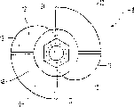
附图2为根据本发明的植入体的近端视图;
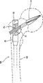
附图3为根据本发明的植入体与侧板配合植入到股骨内时的侧剖面图;
附图4表示根据本发明的植入体与髓内骨钉配合植入到股骨内时的侧剖面示图;
附图5为本发明另一实施方式中的植入体的局部剖视透视图;
附图6为图5所示的实施例的远端视图。
具体实施方式
参照附图1,一个人造骨骼钉8包括多个呈螺旋状盘曲的叶片10及叶片12,这些叶片固定设置在一个杆体16的近端部分14上,在对最佳实施例的这一部分描述说明中,“远端”和“近端”这两个术语的定义是与植入该装置的外科医生有关的,即一个元件的近端一般要比其远端更靠近身体的中央部位。杆体16与叶片10及12的共同螺旋轴线同轴。叶片10、12的形状基本扁平并具有锋利的近端边缘。叶片的螺旋扭曲角至少为30°,最好在45°至120°角之间,尤其最好为90°。螺旋的部分应保证骨钉8可以由其远端旋入股骨内。在植入后,这样的螺距还应该能阻止骨钉8沿其螺旋轴线相对于股骨头向前或向后滑动。
本发明的最佳实施例包括一对在螺旋轴线对侧对置安装的均匀叶片10,该叶片在外形上具有基本一致的叶片宽度;实施例还包括一对安装在螺旋轴线对侧的锥形叶片12,该叶片12的安装位置基本与均匀叶片10成90°角。但是,由至少两个相邻的叶片所成的角17在沿着螺旋线的任意位置,却可以是小于180°的任何角值。一般最好使该角值在30°到150°之间,更优的为在60°至120°之间。在设置了四个叶片的条件下,夹角最理想的情况为90°。锥形渐缩叶片12在其远端18具有最大的叶片宽度,并由此在向近端20延伸的方向上向前渐缩,直到与杆体16的近端部分14的外表面平齐。在附图1中,两个叶片12的两个近端20只有一个是可见的,在图中的位置状态下,另一个近端20刚好隐藏在杆体16的后面。
沿着杆体16的内部有一根中空的管体24。该管体24的尺寸应保证可以插入一个导引线绳(图中未示出),如该领域人员所公知的,该导引线绳用于在植入过程中帮助实现骨钉的正确定位对齐。
图2为从骨钉近端的视图,从图中可以看到叶片10及12的螺旋形状及叶片12的锥形渐缩。图中还表示出了由叶片10及叶片12所夹的角度17。在这样的观察角度上,锥形渐缩叶片12的远端18直接位于均匀叶片10近端顶梢的后面,从而在图中是不可见的。
在图3所推荐的植入定位状态的实施例中,采用了一个侧板26。如图3所示,侧板26与股骨29的骨体28成对齐排列并通过紧固件30固定在骨体28的外侧面。在一实施例中,侧板26的一部分可以相对于紧固件30垂直滑动,以允许断骨的垂向挤压。杆体16的远端部分即一套嵌配合部分22可以在一个柱状套筒32内套叠伸缩式滑动,而柱状套筒32以夹角33固定于侧板26上,夹角33的角度一般在90°到150°之间,但具体如何选择则要根据患者各自的解剖生理结构。当然也可以有其它形式的实施方式,侧板可以按一种固定板的形式进行配置和确定尺寸,并且相对于紧固件不能垂向移动。固定式或可滑动式托板的长度、宽度及其它尺寸的选择都可以由该领域普通技术人员来完成。
用于固定骨钉的植入步骤程序在该领域也是公知的,这些程序也同样适用于本发明。在优选的植入定位方式中,套筒32从股骨29的侧面穿入,伸向股骨骨颈34及股骨头36。在该实施例中,杆体16的远端部分即套嵌配合部分22具有比杆体近端部分14大的外径尺寸。该套嵌配合部分22可滑动地接合在套筒32内,从而使得叶片10、12的远端端头与套筒的近端端头38相分离。这样的分离状态可以使得当股骨头36在远端在螺旋轴线方向上受到挤压时骨钉8可以向后滑回到套筒32内。这就避免了在植入后叶片10、12对股骨头36进一步的切割。
骨钉8植入在股骨29的骨颈34和股骨头36的内部,均匀叶片10的远端部分保持与股骨骨体28平行的定向,而锥形渐缩叶片12的远端部分18则垂直于股骨骨体28。在这样的定向条件下,在叶片的近端端头部分,均匀叶片10与股骨骨体的方向正交,而锥形叶片12及近端端头20则与股骨骨体平行,从而均匀叶片10宽大的近端部分对作用于股骨头36上的基本向下的载荷提供了一个大的正交支撑面,其中的基本向下的载荷是当患者直立和行走时产生的。这就减小了股骨29内部作用于网状组织上的压力,从而防止了叶片割穿骨表层组织的趋势。与基本载荷成一线对齐的均匀叶片10的远端部分增大了杆体16抵抗载荷的弯曲刚度,并有效地将载荷传递到侧板26上。锥形渐缩叶片12的锥形在其远端部分18处也另外增加了杆体的刚性,这是因为在此处叶片12具有大一些的宽度,但在锥形的近端20则保证了骨钉8的柔顺性。这样,骨钉8的近端部分可能是柔韧的,而不会切穿或压碎骨组织。此外,由锥形叶片12所产生的额外的表面积也阻止叶片10、12侧向相对移动进入股骨29的倾向。此外,如果骨钉8在外力作用下侧向挤入骨组织,骨组织将被嵌入由相邻的叶片10及叶片12形成的夹角区域内,这就进一步地限制了骨钉8的移动。套筒32的外径最好大致等于骨钉上最宽部分的尺寸,这样骨钉8就可以从为插入套筒32而钻的孔中方便地装入,从而使骨钉达到上述定位状态的工作变得简单。
在图4中表示了本发明的另一个实施例。在该实施例中采用了一个植入在股骨骨体28内的髓内骨钉40。正如对第一实施例所描述的那样,骨钉8可以沿髓内骨钉40内的孔道42伸缩式地滑动。孔道42与髓内骨钉40的长度方向形成一个夹角44,该夹角的角度一般在90°到150°之间,具体选择要根据股骨的实际形状。
在植入过程中,首先将髓内骨钉40钉入骨内。然后将骨钉8穿过一个孔从股骨29的侧面植入,其中所述孔的深度只钻到髓内骨钉40侧表面。在孔道42上径向形成一系列螺旋沟槽46,其形状适于容纳叶片10及12。如该领域普通技术人员所熟悉的那样,在将骨钉8锤击入骨内时,叶片10及12滑动通过沟槽46。
本实施例最佳的植入定向方式类似于采用侧板的情况。骨钉8与股骨29的相互位置关系与第一实施例的情况相同并具有相同的优点。
在本发明的另外一个实施例中,无论是采用侧板还是髓内骨钉,在骨钉8的远端设置了一个六角形的凹腔48,该凹腔48与杆体16及管体24的近端基准同轴。该凹腔的形状可以容纳某一仪器的端梢,该仪器在该领域是常用的,用于在植入的过程中方便地调节骨钉圆周方向的定位。凹腔48可以根据所使用仪器的不同而采用不同的 形状。例如,不采用中心部位的凹腔,在杆体16的远端或侧壁可以设置多个凹陷或凸起部分来与所使用的仪器配合。
本发明涉及的植入体各个部分的长度和尺寸比例可以由外科大夫根据患者的生理解剖条件进行确定。可以进行选择的尺寸参数例如有骨钉8的长度、侧板26的尺寸及髓内骨钉40的尺寸等。同样,如果需要的话,其它的实施例可能具有不同数目的叶片。
可以预计,本领域技术人员将在本发明的基础上设计出多种变型和实施方式,但所有基于本发明设计思想的变型和实施方式均在本申请要求保护的范围之内。
Claims (19)
1.一种用于固定断骨(29)的植入体,该植入体包括一个骨钉(8),该骨钉(8)具有用于植入断骨内的多个呈螺旋状盘曲的叶片(10,12),所述的叶片(10,12)位置相互固定并沿一共同的螺旋轴线对齐定位,而且在垂直于所述螺旋轴线的平面内,至少有两个所述螺旋叶片成小于180°的角度,其特征在于:所述的螺旋叶片(10,12)至少包括一个向着其要插入骨内的近端宽度渐缩的锥形渐缩叶片(12),所述锥形渐缩叶片具有以所述螺旋轴线为基准测量的近端宽度及远端宽度,所述远端宽度大于所述近端宽度。
2.根据权利要求1所述的植入体,该植入体还包括一个固定件(26,40),该固定件可以固定在骨(29)的一个延伸部分(28)上,所述的叶片(10,12)与所述的固定件(26,40)接合。
3.根据权利要求1所述的植入体,其特征在于:所述的叶片(10,12)基本上是扁平的,而且至少有两个所述叶片(10,12)所成的夹角(17)在30°到150°之间。
4.根据权利要求1所述的植入体,其特征在于:所述的螺旋叶片(10,12)的螺旋部分使得其可以旋入骨(29)内,而且至少有两个叶片(10,12)所成的夹角在60°到120°之间。
5.根据权利要求1所述的植入体,其特征在于:所述螺旋叶片(10,12)围绕其螺旋轴线的螺旋扭曲角至少为30°。
6.根据权利要求2所述的植入体,其特征在于:所述的远端宽度对着所述固定件(26,40)设置。
7.根据权利要求1所述的植入体,其特征在于:至少一个所述的锥形叶片(12)围绕所述螺旋轴线的扭曲角为45°到120°。
8.根据权利要求1所述的植入体,其特征在于:所述的锥形叶片(12)扭曲角为90°,所述的骨钉(8)的植入状态使得所述锥形叶片(12)的远端宽度与骨(29)的延伸部分(28)平行。
9.根据权利要求2所述的植入体,其特征在于:所述的叶片(10,12)与固定件(26,40)之间为可动接合。
10.根据权利要求1所述的植入体,其特征在于:所述的叶片(10,12)在平行于所述螺旋轴线的方向上可滑动地与固定件(26,40)连接,从而允许对断骨块的挤压。
11.根据权利要求1所述的植入体,其特征在于:该植入体的骨钉(8)还包括一个套嵌配合部分(22),该部分可与固定件(26)实现套叠伸缩式的连接关系。
12.根据权利要求2所述的植入体,其特征在于:所述的固定件(26,40)包括一个套筒(32),用于容纳所述的骨钉(8)。
13.根据权利要求12所述的植入体,其特征在于:所述的套筒(32)包括一个外部套筒直径,而且由所述的螺旋叶片(10,12)确定的螺旋直径至多与所述的外部套筒直径大小相同。
14.根据权利要求12或13所述的植入体,其特征在于:在所述的固定件(26,40)上设置了多个从套筒(32)的内部延伸并且与其对齐的螺旋沟槽(46),所述的螺旋叶片(10,12)可以在所述的沟槽(46)中滑动。
15.根据权利要求1所述的植入体,其特征在于:所述的骨钉(8)还包括一个中空的杆体(16),用于容纳一个导引线绳,所述的中空杆体(16)与所述的螺旋轴线共轴地延伸。
16.根据权利要求2所述的植入体,其特征在于:所述的固定件(26)可以固定在骨(29)延伸体的外侧部分(28)上。
17.根据权利要求2所述的植入体,其特征在于:所述的固定件(40)包括一个插入到骨(29)延伸部分(28)内的髓内骨钉,该髓内骨钉的插入方向大致与骨(29)延伸部分(28)平行。
18.根据权利要求2所述的植入体,其特征在于:所述的固定件(26,40)与所述的螺旋轴线所成的角在90°至150°之间。
19.一种用于固定断骨(29)的骨钉(8),该骨钉包括:
A)一个确定螺旋轴线的杆体(16);
B)一对设置在杆体(16)上的均匀宽度的叶片(10);
其特征在于:
C)在杆体(16)上设置的一对宽度锥形渐缩的叶片(12),渐缩叶片(12)的安装方式应使得每一渐缩叶片(12)都处于两个均匀宽度的叶片(10)之间,所述的锥形叶片(12)在其远端宽度最大,而在其近端则宽度最小,所述的宽度均匀叶片(10)和渐缩叶片(12)围绕螺旋轴线具有至少30°的总的螺旋扭曲角;以及
D)所述的骨钉(8)是可以推入骨(29)内部的,并具有一个套嵌配合部分,这个套嵌配合部分与固定件(26,40)保持可滑动连接,所述的固定件(26,40)可以被固定于骨(29)的一个延伸部分(28)上。
Applications Claiming Priority (2)
| Application Number | Priority Date | Filing Date | Title |
|---|---|---|---|
| US08/782,231 US5741256A (en) | 1997-01-13 | 1997-01-13 | Helical osteosynthetic implant |
| US08/782,231 | 1997-01-13 |
Publications (2)
| Publication Number | Publication Date |
|---|---|
| CN1244105A CN1244105A (zh) | 2000-02-09 |
| CN1158974C true CN1158974C (zh) | 2004-07-28 |
Family
ID=25125427
Family Applications (1)
| Application Number | Title | Priority Date | Filing Date |
|---|---|---|---|
| CNB971812780A Expired - Fee Related CN1158974C (zh) | 1997-01-13 | 1997-12-09 | 人造骨骼螺旋植入体 |
Country Status (12)
| Country | Link |
|---|---|
| US (2) | US5741256A (zh) |
| EP (1) | EP0961587B1 (zh) |
| JP (1) | JP4131989B2 (zh) |
| CN (1) | CN1158974C (zh) |
| AT (1) | ATE250892T1 (zh) |
| AU (1) | AU712089B2 (zh) |
| CA (1) | CA2276290C (zh) |
| DE (1) | DE69725342T2 (zh) |
| ES (1) | ES2207761T3 (zh) |
| HK (1) | HK1021930A1 (zh) |
| TW (1) | TW391874B (zh) |
| WO (1) | WO1998030164A1 (zh) |
Families Citing this family (141)
| Publication number | Priority date | Publication date | Assignee | Title |
|---|---|---|---|---|
| US8070786B2 (en) * | 1993-01-21 | 2011-12-06 | Acumed Llc | System for fusing joints |
| US9161793B2 (en) | 1993-01-21 | 2015-10-20 | Acumed Llc | Axial tension screw |
| EP0917449B1 (de) * | 1996-07-31 | 2003-02-05 | Synthes Ag Chur | Vorrichtung zum fixieren abgebrochener hüftgelenkköpfe |
| US6648890B2 (en) | 1996-11-12 | 2003-11-18 | Triage Medical, Inc. | Bone fixation system with radially extendable anchor |
| US6632224B2 (en) | 1996-11-12 | 2003-10-14 | Triage Medical, Inc. | Bone fixation system |
| EP0948293B1 (en) * | 1996-12-02 | 2002-09-25 | SYNTHES AG Chur | Flat intramedullary nail |
| EP1006918B1 (en) * | 1997-01-14 | 2007-01-03 | Research Corporation Technologies, Inc | Bone fixation pin with rotary cutting tip |
| WO1999044528A1 (de) * | 1998-03-05 | 1999-09-10 | Synthes Ag Chur | Marknagel mit verriegelungsloch |
| DE29804268U1 (de) | 1998-03-11 | 1998-05-14 | Synthes Ag | Spiralklingen-Insertions-Instrument |
| WO2001034045A1 (en) | 1999-11-11 | 2001-05-17 | Synthes Ag Chur | Radially expandable intramedullary nail |
| AU2001231272A1 (en) * | 2000-02-02 | 2001-08-14 | Owen A. Nelson | An orthopedic implant used to repair intertrochanteric fractures and a method for inserting the same |
| US6533789B1 (en) * | 2000-04-04 | 2003-03-18 | Synthes (Usa) | Device for rotational stabilization of bone segments |
| US6409730B1 (en) | 2000-05-31 | 2002-06-25 | Synthes (Usa) | Humeral spiral blade |
| AU2001216855A1 (en) * | 2000-12-08 | 2002-06-18 | Synthes Ag, Chur | Device for fixing bones, particularly vertebral bodies, in relation to one another |
| US6511481B2 (en) | 2001-03-30 | 2003-01-28 | Triage Medical, Inc. | Method and apparatus for fixation of proximal femoral fractures |
| US6887243B2 (en) | 2001-03-30 | 2005-05-03 | Triage Medical, Inc. | Method and apparatus for bone fixation with secondary compression |
| US7144413B2 (en) | 2001-04-20 | 2006-12-05 | Synthes (U.S.A.) | Graft fixation system and method |
| US6835197B2 (en) * | 2001-10-17 | 2004-12-28 | Christoph Andreas Roth | Bone fixation system |
| US8828067B2 (en) * | 2001-10-18 | 2014-09-09 | Orthoip, Llc | Bone screw system and method |
| US6685706B2 (en) * | 2001-11-19 | 2004-02-03 | Triage Medical, Inc. | Proximal anchors for bone fixation system |
| DE20208922U1 (de) * | 2002-06-05 | 2003-10-09 | Stryker Trauma Gmbh | Schenkelhalsschraube |
| US6793678B2 (en) | 2002-06-27 | 2004-09-21 | Depuy Acromed, Inc. | Prosthetic intervertebral motion disc having dampening |
| WO2004008949A2 (en) | 2002-07-19 | 2004-01-29 | Triage Medical, Inc. | Method and apparatus for spinal fixation |
| US7179260B2 (en) * | 2003-09-29 | 2007-02-20 | Smith & Nephew, Inc. | Bone plates and bone plate assemblies |
| AU2002328243A1 (en) * | 2002-10-01 | 2004-04-23 | Synthes Ag Chur | Device for fixing bones |
| ATE378012T1 (de) * | 2002-10-29 | 2007-11-15 | Synthes Gmbh | Vorrichtung zur behandlung von frakturen des femur |
| US7070601B2 (en) | 2003-01-16 | 2006-07-04 | Triage Medical, Inc. | Locking plate for bone anchors |
| BR0318151A (pt) * | 2003-03-07 | 2006-02-21 | Synthes Ag | parafuso de travamento para uma garra intramedular |
| WO2004098453A2 (en) * | 2003-05-06 | 2004-11-18 | Triage Medical, Inc. | Proximal anchors for bone fixation system |
| US7951176B2 (en) * | 2003-05-30 | 2011-05-31 | Synthes Usa, Llc | Bone plate |
| BR0318327B1 (pt) * | 2003-06-12 | 2013-06-18 | garra cirérgica. | |
| ES2348003T3 (es) * | 2003-06-12 | 2010-11-26 | Synthes Gmbh | Clavo quirúrgico. |
| DE50311031D1 (de) * | 2003-07-30 | 2009-02-12 | Synthes Gmbh | Chirurgischer nagel |
| US11259851B2 (en) | 2003-08-26 | 2022-03-01 | DePuy Synthes Products, Inc. | Bone plate |
| BR0318428A (pt) | 2003-08-26 | 2006-08-01 | Synthes Gmbh | placa de osso |
| WO2005020830A1 (de) | 2003-08-29 | 2005-03-10 | Synthes Gmbh | Marknagel |
| US7799030B2 (en) * | 2003-09-08 | 2010-09-21 | Smith & Nephew, Inc. | Orthopaedic plate and screw assembly |
| US20050055024A1 (en) * | 2003-09-08 | 2005-03-10 | James Anthony H. | Orthopaedic implant and screw assembly |
| US7780667B2 (en) * | 2003-09-08 | 2010-08-24 | Smith & Nephew, Inc. | Orthopaedic plate and screw assembly |
| KR101050877B1 (ko) * | 2003-09-08 | 2011-07-20 | 신세스 게엠바하 | 뼈 고정 장치 |
| KR101036055B1 (ko) * | 2003-09-18 | 2011-05-19 | 신세스 게엠바하 | 대퇴부 골절의 치료 장치 |
| US8105367B2 (en) * | 2003-09-29 | 2012-01-31 | Smith & Nephew, Inc. | Bone plate and bone plate assemblies including polyaxial fasteners |
| CA2545487C (en) * | 2003-10-21 | 2012-05-01 | Synthes (U.S.A.) | Intramedullary nail |
| US8574268B2 (en) | 2004-01-26 | 2013-11-05 | DePuy Synthes Product, LLC | Highly-versatile variable-angle bone plate system |
| US11291484B2 (en) | 2004-01-26 | 2022-04-05 | DePuy Synthes Products, Inc. | Highly-versatile variable-angle bone plate system |
| BRPI0418604B8 (pt) * | 2004-03-03 | 2021-06-22 | Synthes Gmbh | componente fixador ósseo |
| US8070750B2 (en) | 2004-03-05 | 2011-12-06 | Depuy Mitek, Inc. | Tunnel notcher and guidewire delivery device |
| WO2005096977A1 (en) * | 2004-04-12 | 2005-10-20 | Navin Thakkar | An implant assembly for proximal femoral fracture |
| ATE426366T1 (de) * | 2004-06-22 | 2009-04-15 | Synthes Gmbh | Intramedullarer marknagel |
| WO2006000109A1 (de) * | 2004-06-24 | 2006-01-05 | Synthes Gmbh | Marknagel |
| US8066706B2 (en) * | 2004-06-30 | 2011-11-29 | Synthes Usa, Llc | Surgical nail |
| WO2006023793A2 (en) * | 2004-08-20 | 2006-03-02 | Triage Medical, Inc. | Method and apparatus for delivering an agent |
| US8287541B2 (en) | 2005-05-18 | 2012-10-16 | Sonoma Orthopedic Products, Inc. | Fracture fixation device, tools and methods |
| CA2608693A1 (en) | 2005-05-18 | 2006-11-23 | Sonoma Orthopedic Products, Inc. | Minimally invasive actuable bone fixation devices, systems and methods of use |
| US8961516B2 (en) | 2005-05-18 | 2015-02-24 | Sonoma Orthopedic Products, Inc. | Straight intramedullary fracture fixation devices and methods |
| US9060820B2 (en) | 2005-05-18 | 2015-06-23 | Sonoma Orthopedic Products, Inc. | Segmented intramedullary fracture fixation devices and methods |
| ES2346670T3 (es) * | 2005-08-15 | 2010-10-19 | Synthes Gmbh | Dispositivo de osteosintesis. |
| US7955358B2 (en) | 2005-09-19 | 2011-06-07 | Albert Todd J | Bone screw apparatus, system and method |
| WO2007038560A1 (en) * | 2005-09-28 | 2007-04-05 | Smith & Nephew, Inc. | Instrumentation for reducing fractures , particularly femoral neck |
| CA2624091C (en) * | 2005-12-22 | 2011-08-16 | Hugh S. West, Jr. | Bone anchors for use in attaching soft tissue to bone |
| EP2018127B1 (en) * | 2006-04-21 | 2010-05-19 | Synthes GmbH | Hip helical implant |
| US20080003255A1 (en) | 2006-05-10 | 2008-01-03 | Synthes (Usa) | Method for augmenting, reducing, and repairing bone with thermoplastic materials |
| US20090198237A1 (en) * | 2006-05-10 | 2009-08-06 | David Downey | Method for augmenting, reducing, and repairing bone with thermoplastic materials |
| DE102006057019B4 (de) * | 2006-08-21 | 2008-07-31 | Teichmann, Gernot, Dr. Dr. | Vorrichtung zur Herstellung einer schneckenförmigen Ausnehmung im Kieferknochen |
| US8758345B2 (en) * | 2006-09-22 | 2014-06-24 | Christopher G. Sidebotham | Interlocking nail geometry and method of use |
| JP4978906B2 (ja) * | 2006-10-17 | 2012-07-18 | 周 中村 | 大腿骨転子部骨折に対する骨折内固定具 |
| AU2007323566A1 (en) | 2006-11-22 | 2008-05-29 | Sonoma Orthopedic Products, Inc. | Fracture fixation device, tools and methods |
| WO2008064665A1 (de) | 2006-12-02 | 2008-06-05 | Gernot Teichmann | Vorrichtung zur herstellung einer schneckenförmigen ausnehmung im kieferknochen |
| US8105382B2 (en) | 2006-12-07 | 2012-01-31 | Interventional Spine, Inc. | Intervertebral implant |
| US7909882B2 (en) | 2007-01-19 | 2011-03-22 | Albert Stinnette | Socket and prosthesis for joint replacement |
| US8317845B2 (en) * | 2007-01-19 | 2012-11-27 | Alexa Medical, Llc | Screw and method of use |
| US7918853B2 (en) * | 2007-03-20 | 2011-04-05 | Smith & Nephew, Inc. | Orthopaedic plate and screw assembly |
| US7998176B2 (en) | 2007-06-08 | 2011-08-16 | Interventional Spine, Inc. | Method and apparatus for spinal stabilization |
| US8900307B2 (en) | 2007-06-26 | 2014-12-02 | DePuy Synthes Products, LLC | Highly lordosed fusion cage |
| EP2471493A1 (en) | 2008-01-17 | 2012-07-04 | Synthes GmbH | An expandable intervertebral implant and associated method of manufacturing the same |
| GB2460909B (en) * | 2008-01-28 | 2010-09-08 | Mark B Sommers | Bone Nail |
| KR20110003475A (ko) | 2008-04-05 | 2011-01-12 | 신세스 게엠바하 | 팽창성 추간 임플란트 |
| EP2341857A2 (en) | 2008-09-26 | 2011-07-13 | Sonoma Orthopedic Products, Inc. | Bone fixation device, tools and methods |
| US9526620B2 (en) | 2009-03-30 | 2016-12-27 | DePuy Synthes Products, Inc. | Zero profile spinal fusion cage |
| CA2765376C (en) | 2009-06-30 | 2017-06-06 | Smith & Nephew, Inc. | Orthopaedic implant and fastener assembly |
| US8449544B2 (en) | 2009-06-30 | 2013-05-28 | Smith & Nephew, Inc. | Orthopaedic implant and fastener assembly |
| WO2011044917A1 (en) * | 2009-10-13 | 2011-04-21 | Zimmer Gmbh | An orthopedic nail and an orthopedic nail system |
| US8449578B2 (en) | 2009-11-09 | 2013-05-28 | Ebi, Llc | Multiplanar bone anchor system |
| US9044272B2 (en) | 2009-11-09 | 2015-06-02 | Ebi, Llc | Multiplanar bone anchor system |
| US9393129B2 (en) | 2009-12-10 | 2016-07-19 | DePuy Synthes Products, Inc. | Bellows-like expandable interbody fusion cage |
| AU2011224329B2 (en) * | 2010-03-11 | 2013-07-11 | The Curators Of The University Of Missouri | Joint implant and prosthesis and method |
| US9724140B2 (en) | 2010-06-02 | 2017-08-08 | Wright Medical Technology, Inc. | Tapered, cylindrical cruciform hammer toe implant and method |
| US9498273B2 (en) | 2010-06-02 | 2016-11-22 | Wright Medical Technology, Inc. | Orthopedic implant kit |
| US8608785B2 (en) | 2010-06-02 | 2013-12-17 | Wright Medical Technology, Inc. | Hammer toe implant with expansion portion for retrograde approach |
| US8979860B2 (en) | 2010-06-24 | 2015-03-17 | DePuy Synthes Products. LLC | Enhanced cage insertion device |
| US9592063B2 (en) | 2010-06-24 | 2017-03-14 | DePuy Synthes Products, Inc. | Universal trial for lateral cages |
| TW201215379A (en) | 2010-06-29 | 2012-04-16 | Synthes Gmbh | Distractible intervertebral implant |
| US9402732B2 (en) | 2010-10-11 | 2016-08-02 | DePuy Synthes Products, Inc. | Expandable interspinous process spacer implant |
| WO2012094647A2 (en) | 2011-01-06 | 2012-07-12 | Bergey Darren L | Interbody vertebral prosthetic device with blade anchor |
| US11701238B2 (en) | 2011-01-06 | 2023-07-18 | Darren L. BERGEY | Compressive, orthopedic, anchoring apparatus and method |
| WO2014018098A1 (en) | 2012-07-26 | 2014-01-30 | DePuy Synthes Products, LLC | Expandable implant |
| CN102755187A (zh) * | 2012-07-31 | 2012-10-31 | 中国人民解放军第三军医大学第三附属医院 | 一种股骨近端经皮锁定动力髋螺旋刀片钉 |
| US20140067069A1 (en) | 2012-08-30 | 2014-03-06 | Interventional Spine, Inc. | Artificial disc |
| US8945232B2 (en) | 2012-12-31 | 2015-02-03 | Wright Medical Technology, Inc. | Ball and socket implants for correction of hammer toes and claw toes |
| US9522070B2 (en) | 2013-03-07 | 2016-12-20 | Interventional Spine, Inc. | Intervertebral implant |
| US9522028B2 (en) | 2013-07-03 | 2016-12-20 | Interventional Spine, Inc. | Method and apparatus for sacroiliac joint fixation |
| US9474561B2 (en) | 2013-11-19 | 2016-10-25 | Wright Medical Technology, Inc. | Two-wire technique for installing hammertoe implant |
| US9770278B2 (en) | 2014-01-17 | 2017-09-26 | Arthrex, Inc. | Dual tip guide wire |
| US9498266B2 (en) | 2014-02-12 | 2016-11-22 | Wright Medical Technology, Inc. | Intramedullary implant, system, and method for inserting an implant into a bone |
| CN105142575A (zh) * | 2014-03-28 | 2015-12-09 | 瑞特医疗技术公司 | 锤状趾植入件 |
| US10045803B2 (en) | 2014-07-03 | 2018-08-14 | Mayo Foundation For Medical Education And Research | Sacroiliac joint fusion screw and method |
| WO2016043751A1 (en) | 2014-09-18 | 2016-03-24 | Wright Medical Technology, Inc. | Hammertoe implant and instrument |
| US9814499B2 (en) | 2014-09-30 | 2017-11-14 | Arthrex, Inc. | Intramedullary fracture fixation devices and methods |
| JP6438033B2 (ja) | 2014-12-19 | 2018-12-12 | ライト メディカル テクノロジー インコーポレイテッドWright Medical Technology, Inc. | 骨髄内インプラント |
| US11426290B2 (en) | 2015-03-06 | 2022-08-30 | DePuy Synthes Products, Inc. | Expandable intervertebral implant, system, kit and method |
| EP3273889B1 (en) * | 2015-03-25 | 2020-12-02 | Pier Giovanni Menci | Intramedullary nail for the treatment of fractures of long bones |
| US9913727B2 (en) | 2015-07-02 | 2018-03-13 | Medos International Sarl | Expandable implant |
| US10413332B2 (en) | 2016-04-25 | 2019-09-17 | Imds Llc | Joint fusion implant and methods |
| US10751071B2 (en) | 2016-04-25 | 2020-08-25 | Imds Llc | Joint fusion instrumentation and methods |
| CN109688980B (zh) | 2016-06-28 | 2022-06-10 | Eit 新兴移植技术股份有限公司 | 具有关节运动接头的可扩张和角度可调节的椎间笼 |
| EP4233801A3 (en) | 2016-06-28 | 2023-09-06 | Eit Emerging Implant Technologies GmbH | Expandable, angularly adjustable intervertebral cages |
| US10905476B2 (en) | 2016-09-08 | 2021-02-02 | DePuy Synthes Products, Inc. | Variable angle bone plate |
| US10624686B2 (en) | 2016-09-08 | 2020-04-21 | DePuy Synthes Products, Inc. | Variable angel bone plate |
| US10820930B2 (en) | 2016-09-08 | 2020-11-03 | DePuy Synthes Products, Inc. | Variable angle bone plate |
| US10299847B2 (en) | 2016-09-22 | 2019-05-28 | Globus Medical, Inc. | Systems and methods for intramedullary nail implantation |
| US10751096B2 (en) | 2016-09-22 | 2020-08-25 | Bala Sundararajan | Systems and methods for intramedullary nail implantation |
| US10492803B2 (en) | 2016-09-22 | 2019-12-03 | Globus Medical, Inc. | Systems and methods for intramedullary nail implantation |
| US11083503B2 (en) | 2016-09-22 | 2021-08-10 | Globus Medical, Inc. | Systems and methods for intramedullary nail implantation |
| US11045242B2 (en) | 2016-09-22 | 2021-06-29 | Globus Medical, Inc. | Systems and methods for intramedullary nail implantation |
| US10537436B2 (en) | 2016-11-01 | 2020-01-21 | DePuy Synthes Products, Inc. | Curved expandable cage |
| US10888433B2 (en) | 2016-12-14 | 2021-01-12 | DePuy Synthes Products, Inc. | Intervertebral implant inserter and related methods |
| EP3391841A1 (en) | 2017-04-20 | 2018-10-24 | Stöckli Group AG | Longitudinal bone implant |
| US10398563B2 (en) | 2017-05-08 | 2019-09-03 | Medos International Sarl | Expandable cage |
| US11344424B2 (en) | 2017-06-14 | 2022-05-31 | Medos International Sarl | Expandable intervertebral implant and related methods |
| US10940016B2 (en) | 2017-07-05 | 2021-03-09 | Medos International Sarl | Expandable intervertebral fusion cage |
| USD921898S1 (en) | 2017-12-22 | 2021-06-08 | Orthocision Inc. | Helical implant |
| US11026727B2 (en) | 2018-03-20 | 2021-06-08 | DePuy Synthes Products, Inc. | Bone plate with form-fitting variable-angle locking hole |
| US10772665B2 (en) | 2018-03-29 | 2020-09-15 | DePuy Synthes Products, Inc. | Locking structures for affixing bone anchors to a bone plate, and related systems and methods |
| US11013541B2 (en) | 2018-04-30 | 2021-05-25 | DePuy Synthes Products, Inc. | Threaded locking structures for affixing bone anchors to a bone plate, and related systems and methods |
| US11446156B2 (en) | 2018-10-25 | 2022-09-20 | Medos International Sarl | Expandable intervertebral implant, inserter instrument, and related methods |
| US10925651B2 (en) | 2018-12-21 | 2021-02-23 | DePuy Synthes Products, Inc. | Implant having locking holes with collection cavity for shavings |
| US11633219B2 (en) | 2019-06-26 | 2023-04-25 | Globus Medical, Inc. | Fenestrated pedicle nail |
| US11426286B2 (en) | 2020-03-06 | 2022-08-30 | Eit Emerging Implant Technologies Gmbh | Expandable intervertebral implant |
| US11850160B2 (en) | 2021-03-26 | 2023-12-26 | Medos International Sarl | Expandable lordotic intervertebral fusion cage |
| US11752009B2 (en) | 2021-04-06 | 2023-09-12 | Medos International Sarl | Expandable intervertebral fusion cage |
| DE102021004940A1 (de) | 2021-10-01 | 2023-04-06 | Westsächsische Hochschule Zwickau, Körperschaft des öffentlichen Rechts | Vorrichtung zur Behandlung von Frakturen |
Family Cites Families (28)
| Publication number | Priority date | Publication date | Assignee | Title |
|---|---|---|---|---|
| DE587317C (de) * | 1932-02-13 | 1933-11-02 | Ernst Axel Johan Ericsson | Nagel zur Behandlung von Knochenbruechen |
| US2627855A (en) * | 1950-04-07 | 1953-02-10 | James W Price | Fracture nail and bone plate |
| US2834342A (en) * | 1956-08-29 | 1958-05-13 | Clyde E Yost | Surgical device for the fixation of fractured bones |
| US3002514A (en) * | 1958-01-24 | 1961-10-03 | Deyerle William Minor | Hip setting pin |
| US3025853A (en) * | 1958-07-07 | 1962-03-20 | Christopher A Mason | Fixation device for fractured femur |
| US3029811A (en) * | 1960-04-25 | 1962-04-17 | Ken Standard Corp | Surgical hip nail |
| US3561437A (en) * | 1967-11-08 | 1971-02-09 | Jose Luis Orlich | Apparatus for fixing fractures of the femur |
| US4103683A (en) * | 1977-06-03 | 1978-08-01 | Neufeld John A | Sub-trochanteric nail |
| SU1071298A1 (ru) * | 1982-09-17 | 1984-02-07 | Koptyukh Vladimir V | Устройство дл остеосинтеза |
| US4628923A (en) * | 1983-11-28 | 1986-12-16 | Medoff Robert J | Axial compression device |
| SU1337074A1 (ru) * | 1985-06-21 | 1987-09-15 | В.В.Коптюх | Устройство дл остеосинтеза |
| US4776330A (en) * | 1986-06-23 | 1988-10-11 | Pfizer Hospital Products Group, Inc. | Modular femoral fixation system |
| DE8703491U1 (zh) * | 1987-03-09 | 1987-04-23 | Waldemar Link Gmbh & Co, 2000 Hamburg, De | |
| CH673762A5 (zh) * | 1987-12-02 | 1990-04-12 | Synthes Ag | |
| CH683963A5 (de) * | 1988-06-10 | 1994-06-30 | Synthes Ag | Fixateur intern. |
| US4978349A (en) * | 1989-08-03 | 1990-12-18 | Synthes (U.S.A.) | Fixation plate |
| US5032125A (en) * | 1990-02-06 | 1991-07-16 | Smith & Nephew Richards Inc. | Intramedullary hip screw |
| CH681595A5 (zh) * | 1990-03-19 | 1993-04-30 | Synthes Ag | |
| CH682300A5 (zh) * | 1990-12-17 | 1993-08-31 | Synthes Ag | |
| CH683024A5 (de) * | 1991-04-16 | 1993-12-31 | Synthes Ag | Verbindungseinrichtung zum verstellbaren Verbinden eines ersten mit einem zweiten Konstruktionselement, insbesondere von Rohren oder Stäben für eine Fixationsvorrichtung. |
| CH685851A5 (de) * | 1991-05-24 | 1995-10-31 | Synthes Ag | Chirurgisches Instrument zum Positionieren von osteosynthetischen Befestigungselementen |
| CH686222A5 (de) * | 1991-05-30 | 1996-02-15 | Synthes Ag | Trochanterstabilisierungsvorrichtung. |
| DE59208301D1 (de) * | 1992-06-25 | 1997-05-07 | Synthes Ag | Osteosynthetische fixationsvorrichtung |
| US5498264A (en) * | 1992-07-21 | 1996-03-12 | Synthes (U.S.A.) | Clamp connection for connecting two construction components for a setting device, particularly an osteosynthetic setting device |
| CA2106777C (en) * | 1992-08-24 | 1999-06-29 | Slobodan Tepic | External fixation device for osteosynthesis |
| WO1994026190A1 (de) * | 1993-05-11 | 1994-11-24 | Synthes Ag Chur | Osteosynthetisches befestigungselement und manipulierhilfe dazu |
| FR2711505B1 (fr) * | 1993-10-25 | 1995-12-29 | Tornier Sa | Dispositif de synthèse des fractures de l'extrémité supérieure du fémur. |
| EP0917449B1 (de) * | 1996-07-31 | 2003-02-05 | Synthes Ag Chur | Vorrichtung zum fixieren abgebrochener hüftgelenkköpfe |
-
1997
- 1997-01-13 US US08/782,231 patent/US5741256A/en not_active Expired - Lifetime
- 1997-11-25 TW TW086117645A patent/TW391874B/zh not_active IP Right Cessation
- 1997-12-09 ES ES97953762T patent/ES2207761T3/es not_active Expired - Lifetime
- 1997-12-09 CN CNB971812780A patent/CN1158974C/zh not_active Expired - Fee Related
- 1997-12-09 JP JP53049498A patent/JP4131989B2/ja not_active Expired - Lifetime
- 1997-12-09 AT AT97953762T patent/ATE250892T1/de not_active IP Right Cessation
- 1997-12-09 CA CA002276290A patent/CA2276290C/en not_active Expired - Fee Related
- 1997-12-09 EP EP97953762A patent/EP0961587B1/en not_active Expired - Lifetime
- 1997-12-09 WO PCT/EP1997/006863 patent/WO1998030164A1/en active IP Right Grant
- 1997-12-09 DE DE69725342T patent/DE69725342T2/de not_active Expired - Lifetime
- 1997-12-09 AU AU57551/98A patent/AU712089B2/en not_active Ceased
-
1998
- 1998-01-20 US US09/008,787 patent/US5908422A/en not_active Expired - Lifetime
-
2000
- 2000-02-11 HK HK00100804A patent/HK1021930A1/xx not_active IP Right Cessation
Also Published As
| Publication number | Publication date |
|---|---|
| ATE250892T1 (de) | 2003-10-15 |
| US5908422A (en) | 1999-06-01 |
| JP2001507965A (ja) | 2001-06-19 |
| JP4131989B2 (ja) | 2008-08-13 |
| EP0961587A1 (en) | 1999-12-08 |
| US5741256A (en) | 1998-04-21 |
| HK1021930A1 (en) | 2000-07-21 |
| EP0961587B1 (en) | 2003-10-01 |
| CA2276290C (en) | 2007-01-09 |
| CN1244105A (zh) | 2000-02-09 |
| AU712089B2 (en) | 1999-10-28 |
| DE69725342T2 (de) | 2004-08-19 |
| DE69725342D1 (de) | 2003-11-06 |
| CA2276290A1 (en) | 1998-07-16 |
| ES2207761T3 (es) | 2004-06-01 |
| AU5755198A (en) | 1998-08-03 |
| TW391874B (en) | 2000-06-01 |
| WO1998030164A1 (en) | 1998-07-16 |
Similar Documents
| Publication | Publication Date | Title |
|---|---|---|
| CN1158974C (zh) | 人造骨骼螺旋植入体 | |
| US6949100B1 (en) | Bone screw for use in orthopaedic surgery | |
| EP3202348B1 (en) | Bone plate with alternating chamfers | |
| US9918757B2 (en) | Bone fixation system | |
| US5312406A (en) | Method of treating an intertrochanteric fracture | |
| US5167663A (en) | Femoral fracture device | |
| JP5651472B2 (ja) | テーパーロックを有する後方椎弓根スクリュー | |
| JP4168311B2 (ja) | 背骨用伸延インプラント | |
| EP1100389B1 (de) | Retrograder tibianagel | |
| US7666207B2 (en) | Fixation device for bones | |
| EP0355411A1 (en) | Intramedullary rod for femur stabilization | |
| US20040243129A1 (en) | Double helical threaded bone screw | |
| JP2003523214A (ja) | 背骨用伸延インプラント | |
| WO2003047423A2 (en) | System and method for bone fixation | |
| EP0491138A1 (de) | Vorrichtung zur Fixation von Knochenbrüchen | |
| CN101849855A (zh) | 可调整的骨板 | |
| EP0359793A1 (en) | Variable length fixation device | |
| WO2002011629A1 (de) | Vorrichtung zum einführen von medizinischen mitteln | |
| MXPA01010122A (en) | Improved bone screw for use in orthopaedic surgery |
Legal Events
| Date | Code | Title | Description |
|---|---|---|---|
| C06 | Publication | ||
| PB01 | Publication | ||
| C10 | Entry into substantive examination | ||
| SE01 | Entry into force of request for substantive examination | ||
| C14 | Grant of patent or utility model | ||
| GR01 | Patent grant | ||
| ASS | Succession or assignment of patent right |
Owner name: SYNTHES LTD. Free format text: FORMER OWNER: SYNTHES AG CHUR Effective date: 20061229 |
|
| C41 | Transfer of patent application or patent right or utility model | ||
| TR01 | Transfer of patent right |
Effective date of registration: 20061229 Address after: Swiss Obbo Dov Patentee after: Synthes AG Address before: Swiss Kurdish Patentee before: Chur Synthes AG |
|
| CF01 | Termination of patent right due to non-payment of annual fee | ||
| CF01 | Termination of patent right due to non-payment of annual fee |
Granted publication date: 20040728 Termination date: 20161209 |