CN1251461C - System and method for demodulation of TURBO encoded signals via pilot assisted coherent demodulation - Google Patents
System and method for demodulation of TURBO encoded signals via pilot assisted coherent demodulation Download PDFInfo
- Publication number
- CN1251461C CN1251461C CNB008125945A CN00812594A CN1251461C CN 1251461 C CN1251461 C CN 1251461C CN B008125945 A CNB008125945 A CN B008125945A CN 00812594 A CN00812594 A CN 00812594A CN 1251461 C CN1251461 C CN 1251461C
- Authority
- CN
- China
- Prior art keywords
- signal
- ratio
- circuit
- log
- data
- Prior art date
- Legal status (The legal status is an assumption and is not a legal conclusion. Google has not performed a legal analysis and makes no representation as to the accuracy of the status listed.)
- Expired - Fee Related
Links
Images


Classifications
-
- H—ELECTRICITY
- H04—ELECTRIC COMMUNICATION TECHNIQUE
- H04B—TRANSMISSION
- H04B1/00—Details of transmission systems, not covered by a single one of groups H04B3/00 - H04B13/00; Details of transmission systems not characterised by the medium used for transmission
- H04B1/69—Spread spectrum techniques
- H04B1/707—Spread spectrum techniques using direct sequence modulation
- H04B1/7097—Interference-related aspects
-
- H—ELECTRICITY
- H03—ELECTRONIC CIRCUITRY
- H03M—CODING; DECODING; CODE CONVERSION IN GENERAL
- H03M13/00—Coding, decoding or code conversion, for error detection or error correction; Coding theory basic assumptions; Coding bounds; Error probability evaluation methods; Channel models; Simulation or testing of codes
- H03M13/63—Joint error correction and other techniques
- H03M13/6337—Error control coding in combination with channel estimation
-
- H—ELECTRICITY
- H03—ELECTRONIC CIRCUITRY
- H03M—CODING; DECODING; CODE CONVERSION IN GENERAL
- H03M13/00—Coding, decoding or code conversion, for error detection or error correction; Coding theory basic assumptions; Coding bounds; Error probability evaluation methods; Channel models; Simulation or testing of codes
- H03M13/03—Error detection or forward error correction by redundancy in data representation, i.e. code words containing more digits than the source words
- H03M13/23—Error detection or forward error correction by redundancy in data representation, i.e. code words containing more digits than the source words using convolutional codes, e.g. unit memory codes
-
- H—ELECTRICITY
- H03—ELECTRONIC CIRCUITRY
- H03M—CODING; DECODING; CODE CONVERSION IN GENERAL
- H03M13/00—Coding, decoding or code conversion, for error detection or error correction; Coding theory basic assumptions; Coding bounds; Error probability evaluation methods; Channel models; Simulation or testing of codes
- H03M13/29—Coding, decoding or code conversion, for error detection or error correction; Coding theory basic assumptions; Coding bounds; Error probability evaluation methods; Channel models; Simulation or testing of codes combining two or more codes or code structures, e.g. product codes, generalised product codes, concatenated codes, inner and outer codes
- H03M13/2957—Turbo codes and decoding
-
- H—ELECTRICITY
- H03—ELECTRONIC CIRCUITRY
- H03M—CODING; DECODING; CODE CONVERSION IN GENERAL
- H03M13/00—Coding, decoding or code conversion, for error detection or error correction; Coding theory basic assumptions; Coding bounds; Error probability evaluation methods; Channel models; Simulation or testing of codes
- H03M13/65—Purpose and implementation aspects
- H03M13/6577—Representation or format of variables, register sizes or word-lengths and quantization
- H03M13/658—Scaling by multiplication or division
-
- H—ELECTRICITY
- H04—ELECTRIC COMMUNICATION TECHNIQUE
- H04L—TRANSMISSION OF DIGITAL INFORMATION, e.g. TELEGRAPHIC COMMUNICATION
- H04L1/00—Arrangements for detecting or preventing errors in the information received
- H04L1/20—Arrangements for detecting or preventing errors in the information received using signal quality detector
Abstract
A telecommunications receiver system for accurately decoding a received composite signal having a data signal component and a pilot signal component. The receiver system includes a first circuit for receiving the composite signal and extracting a pilot signal and a data signal from received composite signal. A second circuit calculates a log-likelihood ratio as a function of a channel estimate based on the pilot signal. A third circuit scales the log-likelihood ratio by predetermined log-likelihood ratio scaling factor and provides an accurate log-likelihood value in response thereto. A fourth circuit decodes the received composite signal based on the accurate log-likelihood value and the data signal.
Description
Background of invention
I. invention field
The present invention relates to communication system.On the whole, the present invention relates to be used to calculate log-likelihood degree (log-likelihood) than system and method to help adopting the auxiliary relevant demodulated received device optimization of pilot tone to decode.
II. description of Related Art
Cellular telecommunication system is characterized in, and is a plurality of such as this mobile transceiver of mobile phone and one or more base station communication.Each transceiver comprises transmitter and receiver.
In the typical transceiver, receiving analog radio frequency (RF) signal by antenna, is intermediate frequency (IF) by RF subordinate's frequency conversion.Signal processing circuit is carried out noise filtering, and by simulation automatic gain control (AGC) circuit adjustment signal amplitude.Intermediate frequency portion makes this signal and base band mixing then, and analog signal is transformed to digital signal.Then digital signal is imported a baseband processor and carried out further signal processing, with output speech or data.
Equally, transmitter receives the numeral input from baseband processor, and input is transformed to analog signal.Make this signal filtering then and up-convert to intermediate frequency by intermediater-frequency stage.Regulate the gain that sends signal, and intermediate-freuqncy signal is up-converted to radio frequency, prepare to be used for radio transmitting.
Link is a channel between transmitter and the receiver.Make the base station and a approach that the channel information bearer cap between the travelling carriage of being associated improves is to strengthen wanted to interfering signal ratio (SIR).Usually SIR is expressed as the ratio of the interference density of the energy of each received information position and received signal.In order to improve power system capacity, the receiver in travelling carriage and the base station must maybe must improve channel SIR with the effectively running of low wanted to interfering signal ratio (SIR).In order to improve SIR, improve the transmission signal power usually, this increases cost, and increases the interference to other travelling carriages, is unpractical in many application therefore.As an alternative, often adopt special encoding scheme to reduce desired SIR.
Signal of communication is added to redundant information in the signal with encoding to relate to.By with redundancy strategy be added to the signal of communication that is sent in the noisy environment, the mistake that noisy channel is introduced is reduced to desired horizontal.As Shannon 1948 given, if the information rate of signal of communication is less than channel capacity, just can be issued to desirable noise level in the situation that need not to reduce information rate.If do not adopt redundancy in the noisy environment, just be difficult to maybe can't obtain the zero defect performance.
Design many codings and decode system, in order to the mistake relevant with interference that is taken place during the transmission information in the control communication system with noise.Coding is a key factor in the high reliability modern digital communication systems.
Raleigh fading signal environment and other users' cochannel disturbs in very general code division multiple access (CDMA) wireless communication system, the ability particular importance that effectively operates in noisy and fading environment.Because moving of travelling carriage, the Doppler frequency displacement in the received signal are caused the Raleigh decline.Cochannel just takes place when cdma communication system keeps the multisystem user disturb, the user of each increase is worked to the increase that cochannel disturbs.Cochannel disturbs usually greater than such as this other form interchannel noises of the white noise that adds (AWGN).
In the Raleigh fading signal environment, the power level of the signal of communication that sends distributes according to Raleigh and fluctuates.Power fluctuates in the dynamic range of 10dB to 50dB usually.Be the function of travelling carriage (being cell phone) speed, the frequency channels of distributing to travelling carriage and overall signal environment the duration of fading.Increase with mobile unit velocity, reduce the duration of fading, causes shorter mistake short pulse.Reduce with mobile unit velocity, increase the duration of fading, causes longer mistake short pulse.
Improve the performance of wireless communication system in noise and Raleigh fading environment, often behind signal coder, adopt interleaver.The code word that interleaver extended coding device is exported, each of constant bit word is separated from each other to be sent in the different time so that give.As a result, each independently decline of position experience of given sign indicating number, the position that wherein is subjected to the influence of mistake short pulse belongs to several code words respectively.The sample of signal that the receiver place receives deinterleaves before decoding.Therefore, the effect of mistake short pulse is expanded on message, so that can enough original error correcting codes come restore data.Existing a few types interleaver comprises diagonal angle, convolution, interblock and block interleaver.
The TURBO sign indicating number by one or more code interleaver separate two or more form the sign indicating number be connected in series or be connected in parallel.Often adopt the TURBO encoder to improve error control and the desired SIR of reduction.Usually with the algorithm that interweaves quite efficiently the TURBO sign indicating number is decoded, so that when the signal to noise ratio (snr) convergence Shannon limit, obtain low error rate.As the essential part of TURBO sign indicating number, must respectively code interleaver and deinterleaver be inserted into respectively between composition code coder and the decoder.The TURBO code performance depends on code interleaver length and structure.Can obtain good TURBO code performance by interleaver with pseudo-random structures.
TURBO decoder and convolutional decoder make decoder capabilities the best with the log-likelihood ratio (LLR) of received signal.LLR is that decoder is used for given specific received signal is determined whether that the probability that sends given code element measures.LLR needs the accurate estimation of a channel coefficients, and this channel coefficients is the measured value that is applied to the plural scaling factor of the signal that sends by channel.Correct LLR value is even more important in the TURBO decoding that makes LLR import the non-linear running that causes unacceptable decoder capabilities through amplifying incorrect part among the LLR is usually used.
Calculate the uncertainty that the existing method of LLR is not with due regard to estimated channel coefficients, and cause the detection and the decoding of suboptimization.Only ought correctly know channel coefficients, just realize optimizing decoding with the existing receiver system of TURBO sign indicating number.But in fact be difficult to know definitely channel coefficients, available just channel estimation value.
The channel that obtains declining through a Raleigh usually is the estimated value of channel coefficients, often reference signal (being pilot signal) is broadcasted with data-signal.Pilot signal is this transmitter is given receiver by this channel radio a predetermined sequence (normally constant signal).
Often broadcast the different pieces of information signal base station with a common pilot signal that will send to the user of running travelling carriage in the base station overlay area.Travelling carriage is set up the phase place and the amplitude of channel estimation value with pilot signal, and these are that the associated data signal is carried out coherent detection is necessary.Travelling carriage also sends pilot signal with its business datum signal.The base station with the travelling carriage pilot signal by carrying out coherent demodulation with above-mentioned the same manner.
To utilize synclator and pilot signal to be called the auxiliary coherent demodulation of pilot tone according to the processing that the modulation signal that is received recovers signal transmitted.Obtain effective coherent detection, the auxiliary coherent CDMA communication system of pilot tone must generate correct channel estimation value according to the reception pilot signal.
In theory, channel has equal influence to pilot signal and data-signal.Receiver provides estimated value to channel coefficients according to known pilot signal and the pilot signal that receives, and the channel coefficients estimated value to this response is provided.Calculate the LLR value with the channel coefficients estimated value.But channel estimation value has error factor.This error factor may get greatly and can't accept when providing channel characteristics by quick and deep fading.Formed incorrect part is to especially being a problem with the communication system of TURBO sign indicating number, and incorrect part may cause the obviously performance of degradation among the LLR.
What adopt in LLR counting circuit and the correlation method at present is channel estimation value.But these circuit and method are not considered the uncertainty of channel estimation value usually.Channel often experiences the degree of depth and Raleigh decline fast, channel estimation value that this may lead to errors and the relatively poor decoding performance that is caused based on the suboptimization log-likelihood ratio of this channel estimation value.
Therefore, exist in the art and adopt the needs of the system of the auxiliary coherent demodulation of pilot tone the optimization method of received signal decoding to one.But further need one in the high efficiency systems of considering correct calculation log-likelihood ratio of probabilistic while of channel estimation value.
Summary of the invention
By the demand in efficient telecommunication receiver of the present invention system reply present technique field, described system is used for the composite signal that receives with data-signal and pilot signal component is decoded.In the one exemplary embodiment, make receiver system of the present invention be fit to use, comprise being used to receive composite signal and first circuit of extraction pilot signal and data-signal in the middle of the reception composite signal with wireless code division multiple address (CDMA) communication system.Second circuit calculates initial log-likelihood ratio as the function of channel estimating according to pilot signal and/or data-signal.Tertiary circuit is calibrated initial log-likelihood ratio by predetermined log-likelihood ratio scaling factor, and responds this correct log-likelihood degree value is provided.The 4th circuit is decoded to the reception composite signal according to correct log-likelihood degree value and data-signal.
In one specific embodiment, pilot signal and data-signal comprise pilot tone sampling and data sampling respectively.Tertiary circuit comprises a carrier wave wanted to interfering signal ratio circuit, is used for partly calculating first wanted to interfering signal ratio and second wanted to interfering signal ratio according to data and pilot signal.First wanted to interfering signal ratio is based on data sampling, and second wanted to interfering signal ratio is then taken a sample based on pilot tone.First signal to noise ratio and second signal to noise ratio with input offer tertiary circuit comprising the scaling factor counting circuit.
One more in the certain embodiments, and first circuit comprises a despreader, is used for according to predetermined spread function the reception composite signal being gone to expand, and responds this spread signal is provided.Spread function is pseudo noise sequence or WALSH function.First circuit further comprises from what remove to extract in the middle of the spread signal pilot signal and data-signal and removes to cover circuit.Tertiary circuit comprises the circuit that is used for calculating according to pilot signal and data-signal main carrier wave wanted to interfering signal ratio; And comprise a data noise variance estimating circuit, be used for the noise variance of the energy signal calculated data signal of deriving according to data-signal with from data-signal.Tertiary circuit comprises that also one is used to calculate the divider circuit as the main carrier wave wanted to interfering signal ratio of the function of the noise variance of the absolute value of energy signal and data-signal; And the data sampling signal to noise ratio circuit and the channel estimating signal to noise ratio circuit that are respectively applied for main snr computation first wanted to interfering signal ratio of basis and second wanted to interfering signal ratio.
Tertiary circuit calculates the log-likelihood ratio scaling factor according to following formula:
Wherein, k is the log-likelihood ratio scaling factor; γ
dIt is first wanted to interfering signal ratio; And γ
δIt is second wanted to interfering signal ratio.
Second circuit comprises pilot signal is carried out filtering and respond this providing through the low pass filter of filtering pilot signal as channel estimation value.First multiplier makes data-signal multiply by the conjugate complex number of channel estimation value selectively, and responds the signal that this provides weighting.Scaling circuit is calibrated to generate initial log-likelihood ratio the real part of weighted signal.Tertiary circuit comprises an additional multipliers, and initial log-likelihood ratio and predetermined scaling factor are multiplied each other, and responds this correct log-likelihood degree value is provided.Second circuit comprises that one provides the filter through the filtering pilot signal with reduction interference components; An and conjugate complex number circuit that calculates through filtering pilot signal conjugate complex number.
Tertiary circuit comprises that one is used to make conjugate complex number and data-signal to multiply by the circuit that generates approximate log-likelihood ratio mutually.Log-likelihood ratio by other scaling factor pairing approximation is further calibrated, and calculates according to above-mentioned formula, to generate correct log-likelihood degree value.
The combination of paths circuit is according to the estimated value optimum organization data-signal and the pilot signal of the interference components of synthetic received signal, and responds this signal with optimum organization and offer tertiary circuit.Tertiary circuit comprises a calibration circuit, with the factor of signal times to be scheduled to of optimum organization, to generate correct log-likelihood degree value.
On the other hand, as mentioned above for the correct log-likelihood degree value of each path computing.Generate through combination log-likelihood degree value by the corresponding log-likelihood degree value addition that makes all paths that convolutional decoder or TURBO decoder will use.
Tertiary circuit comprises carrier wave wanted to interfering signal ratio counting circuit, and it calculates main carrier wave wanted to interfering signal ratio.Carrier wave wanted to interfering signal ratio counting circuit comprises interference estimation circuit, and it estimates the interference components of the composite signal that receives.Carrier wave wanted to interfering signal ratio counting circuit comprises the first that is used to calculate composite signal.Composite signal has needed signal component and interference and/or noise component(s).Signal extracting circuit extracts the estimated value of desired signal component in the middle of the received signal.Noise estimating circuit provides correct noise and/or interference value according to the estimated value and the composite signal of required signal component.
In the one exemplary embodiment, correct receiver system comprises that further one is used for generating rate and/or power control messages and speed and/or power control messages are sent to the circuit that is in the external transceiver of communicating by letter with efficient receiver system.
By utilizing the unique scaling factor that is applied to log-likelihood ratio through tertiary circuit, help novel designs of the present invention.This uniqueness scaling factor is considered the intrinsic error that is comprised according in the pilot signal estimation channel characteristics.By considering the uncertain factor in the pilot signal estimation, the invention provides one and optimize log-likelihood degree value, can improve the communication system performance that adopts TURBO decoding and coding greatly.In addition, by noise and the interference components of correctly estimating received signal, the carrier wave wanted to interfering signal ratio that this unique carrier wanted to interfering signal ratio counting circuit provides is more more accurate than what obtained in the past.
Brief Description Of Drawings
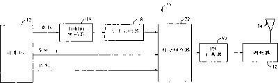
Fig. 1 is according to the demonstrate schematic diagram of code division multiplex (CDM) transmitter that constitutes of the present invention.
Fig. 2 is the schematic diagram of CDM receiver of the present invention.
Fig. 3 is according to the demonstrate schematic diagram of time division multiplexing (TDM) transmitter that constitutes of the present invention.
Fig. 4 is the schematic diagram of TDM receiver of the present invention.
Fig. 5 is the schematic diagram that is used for calculating carrier wave wanted to interfering signal ratio (C/I) and log-likelihood ratio (LLR), is suitable for the circuit that uses with Fig. 2 and Fig. 3 forward link and receiver.
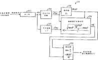
Fig. 6 is the more detailed maps of C/I counting circuit preferred embodiment among Fig. 5.
Fig. 7 is suitable for reverse link and receiver use in Fig. 2 and Fig. 3 the LLR circuit and the circuit diagram of subsidiary transceiver circuit.
Fig. 8 is used for pilot tone sampling and data sampling are offered the interfering energy counting circuit of Fig. 7 LLR circuit and the more detailed maps of optimization combination of paths circuit preferred embodiment.
Fig. 9 is the schematic diagram that is suitable for C/I counting circuit one alternate embodiment that circuit uses in Fig. 5.
The present invention's explanation
Here with reference to one exemplary embodiment explanation the present invention of application-specific, be not limited to this but should understand the present invention.Contact can have the scope of obvious practicality and other modification, application and the embodiment in the other field in the present invention that one skilled in the art will recognize that of this demonstration that provides.
Fig. 1 is the schematic diagram of code division multiplex (CDM) transmitter 10 that constitutes of demonstrating according to the present invention.For clarity sake, the various details of transmitter from accompanying drawing, have been omitted, such as timing circuit, filter and amplifier.Those skilled in the art can be easy to constitute and implement institute's abridged circuit.
Transmitter 10 comprises computer 12, comprises the transmitter software of carrying out by baseband processor (not shown) in the computer 12.Computer 12 is connected to TURBO encoder 14 and time-division combiner 16.The TURBO encoder is connected to channel interleaver 18, channel interleaver 18 is connected to first input of first multiplier 20.The one WALSH function maker 22 is connected to second input of first multiplier 20.The output of first multiplier 20 is connected to first input of combiner 24.
The output of time-division combiner 16 is connected to first input of second multiplier 26, its second input is connected to the 2nd WALSH function maker 28.The output of second multiplier 26 is connected to second input of combiner 24.The output of combiner 24 is connected to orthogonal PN sequence (PN) expander 30.The output of PN expander is input to modulator 32, and described modulator 32 is connected to antenna 34.
In the running, will comprise such as the data form computer 12 of voice data or alternative document data and deliver to TURBO encoder 14.14 pairs of data-signals of TURBO encoder are encoded.TURBO encoder 14 is TURBO encoders of a standard, and according to TURBO coding principle well known in the art and method running.
To interweave by channel interleaver 18 from the encoded data-signal of TURBO encoder 14 outputs then, prepare to carry out WALSH coding, pseudo noise (PN) expansion and modulation.Can implement channel interleaver 18 by the existing interleaver such as block interleaver.
Time-division combiner 16 makes control signal mix with pilot signal according to existing time-division combined method.To be input to the predetermined WALSH function that second multiplier 26 multiply by to be provided by the 2nd WALSH function maker 28 through synthetic signal.Equally, offer another predetermined WALSH function that first multiplier 20 multiply by to be provided by a WALSH function maker 22 with what channel interleaver 18 was exported through the interleaving data signal.
The WALSH sign indicating number that is generated of first multiplier 20 and 26 outputs of second multiplier by 30 expansions of PN expander, is a radio frequency by modulator 32 modulating transformations by combiner 24 combinations then, prepares to be sent by channel by antenna 34.
The signal that generates that sends by antenna 34 is the composite signal with data-signal, pilot signal and control signal.In case by channel radio, composite signal will experience multipath fading and channel disturbance, the receiver system that receives signal transmitted must detect compensation efficiently to this.
Skilled person in the art will appreciate that and can be under the situation that does not deviate from protection range of the present invention substitute a WALSH function maker 22 and the 2nd WALSH function maker 28 provides WALSH function with the combination of pseudo noise function maker or WALSH function maker and pseudo noise function maker.In addition, can in base station and/or travelling carriage, implement transmitter 10.
In this detailed description the term letter disturb with noise be equivalent terms.
Fig. 2 is the schematic diagram that is fit to the CDM receiver 40 of the present invention that the CDM transmitter uses in Fig. 1.Transmitter 40 comprises the receiver antenna 42 that is connected with demodulator circuit 44.Demodulator circuit 44 is connected automatic gain control circuit 46 and A-D converter (ADC) 48 with automatic gain control circuit 46.The output of ADC48 is connected with the first receiver multiplier 50.Also as below will represent the ADC 48 of digital sampling being described in more detail output offer that C/I estimates and the LLR counting circuit as input.
Another input of the first receiver multiplier is connected with 52 outputs of pseudo noise sequence maker.The output of the first receiver multiplier 50 and the input of the second receiver multiplier 54 and the 3rd receiver multiplier 56 are connected in parallel.The first receiver WALSH generator circuit 58 and the second receiver WALSH generator circuit 60 also offer input the second receiver multiplier 54 and the 3rd receiver multiplier 56 respectively.The output of the second receiver multiplier 54 and the 3rd receiver multiplier 56 is connected with the input of first accumulator 62 and second accumulator 64 respectively.The output of first accumulator 62 is connected with despreader with the sampling separator, and described despreader offers output carrier wave wanted to interfering signal ratio (C/I) estimating circuit and log-likelihood ratio (LLR) counting circuit as following being described in more detail.
In the running, the RF signal that the signal that is sent on antenna 42 receive channels of receiver 40 for example sends by transmitter among Fig. 1 10.The RF signal transformation that is received is an intermediate-freuqncy signal, then is transformed to baseband signal by demodulator 44.Regulate the gain of baseband signal by automatic gain control circuit 46, then be transformed to digital signal by A-D converter (ADC) 48.Next, by the PN sequence generator 52 and the first receiver multiplier 50 baseband signal and PN sequence are multiplied each other, PN sequence used in described PN sequence and the PN expander is relevant.In this specific embodiment, PN sequence and inverse thereof are identical, because with binary operation (among the GF2), 1 inverse is 1, and 0 inverse is 0.
Then, 50 outputs of the first receiver multiplier are removed spread signal through part, and it is separated to two independent paths.The second receiver multiplier 54 will multiply by the WALSH function that the first receiver WALSH function maker 58 provides through the sequence that part goes to expand on one path.The WALSH function that a WALSH function maker 22 provides among the WALSH function that is provided and Fig. 1 is relevant.With generated through going spread signal sampling to input to first accumulator 62, the sampling of predetermined number is added up.Offered sampling separator 66 with what add up through going growth data to take a sample.The sampling separator 66 as below be described in more detail, will export C/I estimating circuit and LLR circuit to from the pilot signal and the control signal of going to extract in the middle of the spread signal.
Equally, second accumulator 64 add up the output of the 3rd receiver multiplier 56 through going the spread signal sampling, described second accumulator 64 as below be described in more detail, will comprise that the data-signal that data-signal is taken a sample exports C/I estimating circuit and LLR circuit to.
In this specific embodiment; the present invention is fit to use with binary phase shift keying (BPSK) or Quadrature Phase Shift Keying (QPSK) modulation-demo-demodulation method; but skilled person in the art will appreciate that and under the situation that does not deviate from protection range of the present invention, to use other modulation-demo-demodulation methods.
Fig. 3 is according to the demonstrate schematic diagram of time division multiplexing (TDM) transmitter 70 that constitutes of the present invention.CDM transmitter 10 is same among TDM transmitter 70 and Fig. 1, and just the time spent is divided time-division combiner 16 in combiner 72 alternate figures 1, multiplier 20 and 26, WALSH function maker 22 and 28 and adder 24.
Fig. 4 is the schematic diagram of TDM receiver 80 of the present invention.CDM receiver 40 is same among TDM receiver 80 and Fig. 2, just the multiplier 54 and 56 in accumulator 82 and TDM sampling separator 84 alternate figures 2, WALSH function generator circuit 58 and 60, accumulator 62 and 64 and sampling separator 66.Accumulator 82 receives the digital extended sampling from multiplier 50, and sampling is added up, and then add up sampling is offered TDM sampling separator 84.TDM sampling separator 84 from add up and in the middle of the past expansion of digital signal, extract data sampling, pilot tone sampling and control sampling.Data sampling, pilot tone sampling, control sampling and digital sampling with ADC 48 outputs as following being described in more detail offer C/I estimation and LLR circuit.
Fig. 5 is the schematic diagram that is used to calculate the circuit 90 of carrier wave wanted to interfering signal ratio (C/I) and log-likelihood ratio (LLR), and this circuit is fit to being respectively that forward link and receiver 40 and 80 among Fig. 2 and Fig. 4 uses.Circuit 90 comprises carrier wave wanted to interfering signal ratio (C/I) counting circuit 92, low pass filter 94 and LLR circuit 96.
C/I counting circuit 92 receives data sampling, pilot tone sampling and control sampling as input.Output by low pass filter 94 provides an other channel estimating input.Low pass filter 94 is pilot signal filters, receives the pilot tone sampling, and filtering is carried out in sampling to pilot tone, and responds this channel estimating is offered C/I counting circuit 92.The C/I counting circuit 92 response data samplings that receiver receives from Fig. 2 or Fig. 4, pilot tone sampling and control sampling and response export C/I ratio to LLR circuit 96 from the channel estimating that low pass filter 94 receives.
Information that C/I counting circuit 92 can extract according to the information of extracting in the middle of data sampling, in the middle of the pilot tone sampling or the information calculations C/I ratio that extracts in the middle of its composite sampling.If calculate C/I ratio according to data sampling and pilot tone sampling, C/I counting circuit 92 just makes up based on the estimation of data sampling and the estimation of taking a sample based on pilot tone according to following formula:
Wherein, (C/I)
OutBe C/I ratio from 92 outputs of C/I counting circuit; K is less than or equal to 1 predetermined constant; (C/I)
dBe C/I ratio according to data sampling, and (C/I)
pBe C/I ratio according to the pilot tone sampling.Be described in more detail the system that correct C/I value is provided below.
The output of C/I counting circuit 92 can be expressed as:
Wherein, E
sBe the average energy of every data symbols, and σ
z 2It is the noise variance of data sampling.
C/I counting circuit 92 is the C/I estimator, and is available or can control sampling.Skilled person in the art will appreciate that and under the situation that does not deviate from protection range of the present invention, to omit the control sampling.In this specific embodiment, if C/I counting circuit 92 uses control sampling, then expression and the same other data sampling collection of data symbols.
Skilled person in the art will appreciate that and under the situation that does not deviate from protection range of the present invention, data sampling, pilot tone sampling and control sampling to be offered the C/I counting circuit as composite signal.In addition, can also omit the control sampling.
The output of scaling circuit 106 is connected with the input of LLR multiplier 110, its another input is connected with the output of correct scaling factor counting circuit 102.As following being described in more detail, the correct LLR value corresponding to data sampling is represented in the output of LLR multiplier 110, and described data sampling is offered the TURBO decoder to help the decoding of data sampling.
The C/I ratio that data sampling SIR circuit 98 provides according to C/I counting circuit 92 is by multiply by reception C/I ratio another predetermined scaling factor calculated data sampling SIR.Scaling factor is to divide other with using, and those skilled in the art can be easy to determine to meet given demands of applications.By the data sampling SIR that following formulae express generated:
Wherein, γ
dBe data sampling SIR; E
sIt is the average received energy of every data symbols; And σ
s 2It is the noise variance of every data symbols.The data sampling SIR that is generated offers correct scaling factor counting circuit 102.
Channel estimating SIR circuit 100 receives SIR according to the C/I ratio that receives from C/I counting circuit 92 and multiply by predetermined scaling factor calculating channel estimation SIR by making, described predetermined scaling factor is to divide other with using, and those skilled in the art can be easy to determine.By following formulae express channel estimating SIR:
Wherein with top definition, γ
aBe channel estimating SIR; E
sIt is the average received energy of every data symbols; And σ
a 2It is the noise variance in every data symbols time interval of the channel estimating that provides by low pass filter 94.Channel estimating SIR also offers correct scaling factor counting circuit 102.
The channel estimating SIR that data sampling SIR that correct scaling factor counting circuit 102 provides according to data sampling SIR circuit 98 and channel estimating SIR circuit 100 provide calculates correct LLR scaling factor according to following formula:
Wherein, k is correct LLR scaling factor, definition in remaining variables such as formula (3) and (4).
Multiplier 104 multiplies each other the conjugate complex number and the data sampling of the channel estimating of low pass filter 94 outputs.The result is sent to real part extract circuit 105, real part is extracted circuit 105 and is obtained long-pending real part, calibrates by predetermined constant factor by scaling circuit 106, generates approximate LLR and estimates.LLR estimates to be input to LLR multiplier 110 nearly.
The output of scaling circuit 106 represents to be suitable for used LLR ratio in the convolutional coded signal decoding, but that generate when the TURBO code signal decoded is the suboptimization result.
According to the present invention, provide the correct scaling factor of explaining by formula (5) by correct scaling factor counting circuit 102, calibrate by the LLR ratio of 110 pairs of scaling circuits of LLR multiplier, 106 outputs.
Correct LLR value is represented in the output of LLR multiplier 110, as following being described in more detail, helps the effective decoding of TURBO decoder to the TURBO code signal.
Fig. 6 is the more detailed maps of C/I estimating circuit 120 preferred embodiments, and this C/I estimating circuit 120 is corresponding with C/I counting circuit 92 among Fig. 5.C/I estimating circuit 120 is suitable for forward link.In the present embodiment, C/I estimating circuit 120 comprises a PN despreader 122, the multiplier 50 of receiver 80, PN sequence generator 52 and accumulator 82 in the alternate figures 4.M array WALSH removes to cover TDM sampling separator 84 in device circuit 124 alternate figures 4.
From left to right and from top to bottom, C/I estimating circuit 120 comprises that PN despreader 122, M array WALSH remove to cover device circuit 124, total received signal energy (I
o) counting circuit 126, first constant circuit 136, pilot filter 128, subtracter 132, first multiplier 134, pilot energy counting circuit 138, look-up table (LUT) 140, second multiplier 142 and C/I summation circuit 144.In the C/I estimating circuit 120, PN despreader 122 receives the digital homophase (I) and quadrature (Q) signal of ADC 48 outputs among Fig. 4 or Fig. 5.PN despreader 122 offers M array WALSH with parallel way with input and removes to cover device circuit 124 and Io counting circuit 126.M array WALSH removes to cover device circuit 124 input is offered constant divider circuit 130 in pilot filter 128 and the weights combinational circuit 158.
The output of circuit for calculating energy 126 is connected with the anode of subtraction circuit 132.The negative terminal of subtraction circuit 132 is connected with the output of first multiplier 134.First input of first multiplier 134 is connected with the output of first constant circuit 136.Second input of first multiplier 134 is connected with the output of pilot energy counting circuit 138.Pilot filter 128 offers pilot energy counting circuit 138 with input.
The output of subtracter 132 is connected with look-up table (LUT) 140.The output of LUT 140 is connected with first input of the 3rd multiplier 146 in the weights combinational circuit 158 with first input of second multiplier 142 with parallel way.Second input of second multiplier 142 is connected with the output of first multiplier 134.The output of second multiplier 142 is connected with C/I accumulator circuit 144, and its output offers the input of LLR circuit 96.
Weights combinational circuit 158 comprises the second constant generative circuit 150, the 4th multiplier 148, the 3rd multiplier 146, constant divider circuit 130, conjugate complex number circuit 152, the 5th multiplier 154 and path accumulator circuit 156.In the weights combinational circuit 158, the 4th multiplier 148 first ends are connected with the output of pilot filter 128, and this output also is connected with pilot energy counting circuit 138 in the C/I estimating circuit 120.Second end of the 4th multiplier 148 is connected with the second constant generative circuit 150.The output of the 4th multiplier 148 is connected with second input of the 3rd multiplier 146.The output of the 3rd multiplier 146 offers the input of conjugate complex number circuit 152.The output of conjugate complex number circuit 152 is connected with first input of the 5th multiplier 154.The output of constant divider circuit 130 is connected with second input of the 5th multiplier 154.The output of the 5th multiplier 154 is connected with the input of path accumulator circuit 156.The output of path accumulator circuit 156 is connected with second input of LLR circuit 96.The output of LLR circuit and decoder input (referring among Fig. 1 48) is connected.
In the running, PN despreader 122 receives I and Q signal, and L is referred to be that L independent pathway (1) goes expansion.The inverse that is used to expand the pseudo noise sequence of I and Q signal before PN despreader 122 is used in and sends by channel goes expansion to I and Q signal.The formation of PN despreader 122 known in the art and running.
Remove spread signal by PN despreader 122 output, and input to M array WALSH and remove to cover device 124 and I
oCounting circuit 126.I
oCounting circuit 126 calculates the total received energy (I of every chip that comprises desired signal component and interference noise component
o).I
oCounting circuit provides I according to following formula
oEstimated value (^I
o):
Wherein, N is a number of chips in every pilot tone short pulse, is 64 in this specific embodiment, and the spread signal that receives of expression PN despreader 122 outputs.
Skilled person in the art will appreciate that and to go to calculate I before the expansion at PN despreader 122 under the situation that does not deviate from protection range of the present invention
oFor example, I
oCounting circuit 126 can receive the direct input of I that from Fig. 2 and Fig. 4 ADC 48 receives and Q signal but not input that PN despreader 122 is provided, in this case I
oThe output of counting circuit 126 will provide I
oEquivalence estimate.
M array WALSH removes to cover device circuit 124 and according to approach well known orthogonal data signal that is referred to as data channel and the pilot signal that is referred to as pilot channel is gone to cover.In this specific embodiment, the orthogonal data signal is corresponding with a data channel s by following formulate:

The present invention is suitable for comprising the signal of various WALSH sign indicating numbers, but those skilled in the art are easy to make the present invention to be suitable for the other types sign indicating number.
Pilot channel inputs to pilot filter 128.Pilot filter 128 be an effect as the average filter of low pass filter, it removes the noise jamming component of upper frequency in the middle of the pilot channel.Output p by following formulate pilot filter 128:

Wherein, M is a number of chips in every WALSH code element, ^E
P, lBe the pilot chip energy of the 1st multipath component, and θ
lIt is phase place through filtering pilot channel p.
Calculate Energy Estimation by pilot energy counting circuit 138 through filtering pilot channel p, its be formula (8) represented through filtering pilot channel p complex amplitude square.Will be through the predetermined scaling factor c that following formula is explained that square multiply by of filtering pilot channel p complex amplitude:
Wherein, I
OrThe received energy that is desired signal promptly is equivalent to noise jamming component I seldom
oE
pIt is the pilot chip energy.Scaling factor c is a forward link constant known in many wireless communication systems.
The energy that scaling factor c be multiply by through filtering pilot channel p by first multiplier 134 generates hope signal (the noise jamming component I seldom that is received
o) the correct estimation ^I of energy
Or, l, the hope signal that is received is associated with the 1st multipath component of received signal I and Q signal.
By subtracter 132 from I
oDeduct accurate estimation ^I in the middle of the estimation
Or, l, generate the interfering energy (N that is associated with the 1st multipath component
T, l) the correct measurement value.Then with N
T, lOffer LUT 140, with N
T, l goes intoInverse export first input of the 3rd multiplier 146 in the weights combinational circuit 158 and second multiplier 142 to.Second input of second multiplier 142 is connected with the output of first multiplier 134, provides ^I by second input of second multiplier 142
Or, lThe carrier wave wanted to interfering signal ratio (C/I) that second multiplier 142 is associated with the 1st multipath component according to following formula output
lCorrect estimation:

Then, by on the L path of C/I accumulator circuit 144 in received signal correct C/I value being added up.To offer LLR circuit 96 through the C/I value that adds up then and belong to known speed/power request generative circuit (not shown) in the art with its formation.
In the weights combinational circuit 158, the 4th multiplier 148 will multiply by the constant k that the second constant generative circuit 150 provides through filtering pilot channel p.According to following formula computational constant k:
Wherein, E
sBe the modulated symbol energy, E
pBe the pilot frequency code element energy, and M is WALSH code element number in every chip as mentioned above.Send both situations, E for reverse link transmission and forward link
sTo E
pRatio known often or confirmable.
The output of the 4th multiplier 148 provides the estimation to the channel coefficients ^ α of following formulae express:
Wherein, ^E
S, lBe the modulated symbol Energy Estimation of the 1st multipath component, ^ θ
lIt is the phase estimation of pilot signal.
Then make channel estimating multiply by the interfering energy N that is associated with the 1st multipath component by the 3rd multiplier 146
T, lInverse.Interfering energy N
T, lComprise and disturbing and noise component(s).Conjugate complex number circuit 152 then calculates the conjugate of the 3rd multiplier 146 outputs, the weighting of expression maximum ratio combination of paths.Then make the weighting of maximum ratio combination of paths multiply by the corresponding data symbols of divider circuit 130 outputs by the 5th multiplier 154.By following formulate data symbols d:
Wherein, variable such as formula (2) and (7) are given.
The output of the 5th multiplier 154 represents to optimize the data-signal of weighting, by path accumulator circuit 156 they is added up on the L that comprises an above-mentioned signal path then.The data-signal of the optimum organization that generated is offered LLR circuit 96, this circuit help to decoder (as following be described in more detail with Fig. 5 in illustrated) the soft decoder of optimization calculate.
Note among Fig. 5 a path only being shown, so there is not combiner.Otherwise, data sampling, pilot tone sampling and control sampling should be interpreted as a plurality of parallel data streams, each data flow is from different antennas.
The constant c and the k that provide by the first constant generative circuit 136 and the second constant generative circuit 150 respectively are provided, can under the situation that does not deviate from protection range of the present invention are and formula (3) and (6) represented different constants or variable.
Fig. 7 is to be fit to reverse link and is respectively receiver 40 and the LLR circuit 170 of 80 uses and the schematic diagram of subsidiary transceiver circuit 172 among Fig. 2 and Fig. 4.LLR circuit 170 comprises conjugation plural number circuit 174, and its output is connected with the input of first multiplier 176.The output of first multiplier 176 is connected with the input that circuit 105 is extracted in real part, and first input that circuit 105 offers output second multiplier 178 is extracted in real part.Second input of second multiplier 178 is connected with the output of constant factor circuit 188.The output of second multiplier 178 is connected with the input of LLR maker 179, and rough calibration LLR value is represented in described output.The output of LLR maker 179 is connected with the input of TURBO decoder 180, and TURBO decoder 180 will offer data or the Audio Processing Unit 182 that is connected with receiver (in such as Fig. 2 among receiver 40 or Fig. 3 receiver 80) through decoded bits.Data or Audio Processing Unit 182 offer output w radio telephone loud speaker (not shown) or offer other equipment or computer application (not shown).
Pilot tone sampling and data sampling offer LLR maker 179 by receiver among Fig. 2 or Fig. 4.The pilot tone sampling also offers low pass filter 186 as input, and its output then is connected with the input of conjugate complex number circuit 174.
In the running, will input to conjugate complex number circuit 174 in the LLR circuit 170 through the pilot tone sampling of low pass filter 186 filtering.The conjugate that conjugate complex number circuit 174 calculates through the filtering pilot signal outputs to first multiplier 176 with them.First multiplier 176 multiplies each other with receiver (referring to Fig. 2 and Fig. 4) data sampling through the sampling of filtering pilot tone conjugation.Then by predetermined constant factor multiplied signals is calibrated by second multiplier 178 and constant factor circuit 188.Predetermined constant factor is to divide other with using.Those skilled in the art can be easy to calculate suitable factor and constitute provides the circuit of this factor to meet given demands of applications accordingly.
Will from the output of second multiplier 178 generated offer LLR maker 179 through rate-aided signal, LLR maker 179 is carried out and Fig. 5 center 92,98,100 and 102 identical functions basically.
A correct LLR value is represented in the output of LLR maker 179, and it is fit to the TURBO sign indicating number as one and it is characterized in that having relatively low channel wanted to interfering signal ratio and application such as the reverse link of big multipath flare factor is used the LLR value of using and is input to TURBO decoder 180.
The formation of TURBO decoder 180 known in the art, the LLR value that TURBO decoder 180 usefulness are correct is taken a sample to received data and is decoded.The data sampling that is generated is delivered to signal processing circuit such as data or Audio Processing Unit 182, or deliver to a computer that is connected with the receiver terminal of service data process software.
In the present embodiment, controller 182 and transmitter 184 are corresponding with computer 12 and efficient transmitter 10 among Fig. 1 respectively, or corresponding with computer 12 and transmitter 70 among Fig. 3.
Fig. 8 is used for pilot tone sampling and data sampling are offered the interfering energy counting circuit 190 of Fig. 7 LLR circuit and the more detailed maps of optimization combination of paths circuit 158 preferable enforcements.This correct interfering energy counting circuit 190 process aspect the reverse link transmission is optimized, and comprises LLR circuit 96 among weights combinational circuit 158 and Fig. 6.
Except the calculating of Nt, the running of interfering energy counting circuit 190 is the same with the running of C/I estimating circuit 120 among Fig. 6.Interfering energy counting circuit 190 comprises that PN despreader 122, M array WALSH remove to cover device circuit 124 and pilot filter 128.M array WALSH removes to cover device circuit 124 makes pilot channel and data channel go to cover from what PN despreader 122 was exported in the middle of going to expand I and Q signal, promptly extracts pilot channel and data channel.
In the interfering energy counting circuit 190, pilot channel offers the positive input and the pilot filter 128 of pilot tone subtraction circuit 192.Pilot filter 128 suppresses noise and the interference components in the middle of the pilot channel, will offer the negative input of pilot tone subtraction circuit 192 through the pilot signal of filtering.Pilot tone subtraction circuit 192 is from deducting pilot channel in the middle of the filtering pilot channel, the signal of output one expression every symbol interference and noise, this every symbol interference and noise are wherein to adopt channel introducing between the transmission base station (not shown) of interfering energy counting circuit 190 and the transceiver system (referring to transmitter and receiver among Fig. 1 and Fig. 2 and Fig. 3 and Fig. 4).Calculate the interference and the noise signal energy (N of each code element according to following formula by interfering energy counting circuit 194
L, t):
Wherein, M is a number of chips in every WALSH code element, and N is number of chips in the pilot tone short pulse (64 chip), but the output of pilot tone subtraction circuit 192.
Interfering energy counting circuit 190 is provided when the constant value c that is provided when the first constant generative circuit 84 among Fig. 6 is unknown.The used constant k of multiplier 148 time before on the reverse link code element being carried out demodulation may be unknown.Therefore, just in time be before LLR calculates decoding, to carry out multiplication among Fig. 8.It is this situation that many reverse links are used.
Fig. 9 is the schematic diagram that is fit to C/I counting circuit 210 another embodiment that circuit 90 uses in Fig. 5.C/I counting circuit 210 is specific embodiments of C/I counting circuit 92 among Fig. 5.C/I counting circuit 210 can use by C/I estimating circuit 120 in Fig. 6, or is used for alternate figures 6 C/I estimating circuits 120.
C/I counting circuit 210 is fit to use with forward link, and comprises normalization circuit 212.This normalization circuit 212 is connected with squaring circuit 215 with squaring and averaging circuit 214 with parallel way.The output of squaring circuit 215 is connected with Noise Variance Estimation circuit 216.Squaring and averaging circuit 214 is connected with Noise Variance Estimation circuit 216 with absolute value circuit 218 with parallel way.The output of absolute value circuit 218 is connected with first input of Noise Variance Estimation circuit 216 and multiplier 220 with parallel way.Second input of multiplier 220 is connected with the output of Noise Variance Estimation circuit 216.
In the running, divide other normalization factor to received data take a sample normalization by predetermined with using by normalization circuit 212, those skilled in the art can be easy to determine that this normalization factor is to meet given demands of applications.Normalization data sampling is offered squaring and averaging circuit 214, the mean value of calculated complex normalization data sampling square.Squaring circuit 215 also calculates normalization data sampling square, offers Noise Variance Estimation circuit 216.The Energy Estimation of data sampling is represented in the output of squaring and averaging circuit 214, and this output also is input to Noise Variance Estimation circuit 216, the Noise Variance Estimation that this Noise Variance Estimation circuit 216 is taken a sample according to following formula calculated data:
Wherein, σ
2 zIt is the noise variance of normalization data sampling; | ^a (n) |
2The absolute value that is squaring and averaging circuit output is the output of absolute value circuit 218; x
2(n) output of expression squaring and averaging circuit; N is variable estimated time; And N is the data sampling number, and the noise variance of data sampling calculates according to this data sampling number.N divides other with using, and those skilled in the art can be easy to determine to meet given demands of applications.
Exporting the noise variance of the channel estimation value that generated to a divider 220, is the output of absolute value circuit 218 with the squared absolute value of channel estimation value, divided by noise variance σ
2 z, to generate C/I ratio based on suitable correct data sampling.The main signal to noise ratio that is generated promptly should be estimated to generate a C/I through combination according to formula (1) based on the C/I ratio of data and the C/I ratio combination of for example being estimated by 120 pilot tones that generate among Fig. 6.To estimate to input among Fig. 5 channel estimating SIR circuit 100 in the data sampling SIR circuit 98 and Fig. 5 through the C/I of combination.
At this specific embodiment the present invention has been described like this with reference to application-specific.Those skilled in the art will be understood that other modification, application and embodiment in the protection range of the present invention after contacting the present invention's demonstration.
Therefore, plan to contain any and whole this application, modification and embodiment in the protection range of the present invention by appending claims.
Claims (36)
1. an efficient telecommunication receiver system is used for the composite signal that receives with data-signal component and pilot signal component is correctly decoded, and it is characterized in that, comprising:
Be used to receive first device that described composite signal also extracts pilot signal and data-signal thus;
Be used for according to second device of described pilot signal calculating as the log-likelihood ratio of the function of channel estimation value; And
Be used for described log-likelihood ratio being calibrated by predetermined log-likelihood ratio scaling factor, and respond the 3rd device that it provides a correct log-likelihood degree value, wherein the 3rd device draws predetermined log-likelihood ratio scaling factor by calculating first and second wanted to interfering signal ratios; And
Be used for receiving the 4th device that composite signal is decoded to described according to described correct log-likelihood degree value and described data-signal,
Wherein said the 3rd device comprises that one is used to calculate the carrier wave wanted to interfering signal ratio counting circuit of main carrier wave wanted to interfering signal ratio.
2. the system as claimed in claim 1 is characterized in that, described pilot signal and described data-signal comprise pilot tone sampling and data sampling respectively.
3. system as claimed in claim 2 is characterized in that, described the 3rd device comprises that one is used for part is calculated first wanted to interfering signal ratio and second wanted to interfering signal ratio according to described pilot signal carrier wave wanted to interfering signal ratio circuit.
4. system as claimed in claim 3, it is characterized in that, described first wanted to interfering signal ratio is based on described data sampling, described second wanted to interfering signal ratio is then based on the sampling of described pilot tone, and described first signal to noise ratio and described second signal to noise ratio offer a circuit that is used for calculating the described scaling factor that described the 3rd device comprises with input.
5. the system as claimed in claim 1 is characterized in that, described first device comprises: one is used for making the described composite signal that receives go expansion according to the predetermined extended function, and responds this and provide once the despreader that removes spread signal.
6. system as claimed in claim 5 is characterized in that, described spread function is pseudo noise sequence or WALSH function.
7. system as claimed in claim 5 is characterized in that, described first device further comprises: one is used for removing to cover circuit from described through what remove to extract in the middle of the spread signal described pilot signal and described data-signal.
8. the system as claimed in claim 1 is characterized in that, described the 3rd device comprises: the device that is used for calculating according to described pilot signal and described data-signal main carrier wave wanted to interfering signal ratio.
9. system as claimed in claim 8 is characterized in that, described the 3rd device comprises: be used for according to described data-signal and calculate the data noise variance estimating circuit of described data-signal noise variance from the energy signal that described data-signal obtains.
10. system as claimed in claim 9 is characterized in that, described data noise variance estimating circuit comprises: be used for calculating the device of the described noise variance of described data-signal according to following formula,

Wherein, σ
z 2It is the described noise variance of described data-signal;
 It is the absolute value of described energy signal; x
2(n) be described energy signal; N is a discrete-time variable; And N is the data sampling number that it is calculated the described noise variance of described data-signal.
It is the absolute value of described energy signal; x
2(n) be described energy signal; N is a discrete-time variable; And N is the data sampling number that it is calculated the described noise variance of described data-signal.
11. system as claimed in claim 9 is characterized in that, described the 3rd device comprises: be used to calculate the divider circuit as the described main carrier wave wanted to interfering signal ratio of the function of described energy signal absolute value and the described noise variance of described data-signal.
12. system as claimed in claim 11 is characterized in that, further comprises: the data sampling signal to noise ratio circuit and the channel estimating signal to noise ratio circuit that are used for calculating respectively first wanted to interfering signal ratio and second wanted to interfering signal ratio according to described main signal to noise ratio.
13. system as claimed in claim 12 is characterized in that, described the 3rd device calculates described log-likelihood ratio scaling factor according to following formula:
Wherein, k is described log-likelihood ratio scaling factor; γ
dIt is described first wanted to interfering signal ratio; And γ
_It is described second wanted to interfering signal ratio.
14. system as claimed in claim 13 is characterized in that, by the described first wanted to interfering signal ratio γ of following formulae express
d:
E wherein
sBe the average energy of described pilot signal, and σ
2 sIt is the described noise variance that receives composite signal.
15. system as claimed in claim 13 is characterized in that, by the described second wanted to interfering signal ratio γ of following formulae express
_:
E wherein
sBe the average energy of described pilot signal, and σ
a 2It is the noise variance of the described pilot signal of low pass filter output.
16. the system as claimed in claim 1 is characterized in that, described second device comprises: be used for described pilot signal is carried out filtering and respond this providing through the low pass filter of filtering pilot signal as channel estimating.
17. system as claimed in claim 16 is characterized in that, described second device comprises: be used for selectively described data-signal being multiply by the conjugate complex number of described channel estimating and respond this first multiplier through weighted signal is provided.
18. system as claimed in claim 17 is characterized in that, described second device comprises: be used for predetermined constant factor the scaling circuit that this generates initial log-likelihood ratio being calibrated and responded in described real part through weighted signal.
19. system as claimed in claim 18 is characterized in that, described the 3rd device comprises: be used for described initial log-likelihood ratio be multiply by described predetermined scaling factor and responds second multiplier that this provides described correct log-likelihood degree value.
20. the system as claimed in claim 1 is characterized in that, described second device comprises: be used to provide one to have the filter through the filtering pilot signal that reduces interference components; And be used to provide the conjugate complex number circuit of described conjugate complex number through the filtering pilot signal as output.
21. system as claimed in claim 20, it is characterized in that, described the 3rd device comprises: be used for described conjugate complex number be multiply by described data-signal to generate a result device, calibrate responding the described result that this generates rough log-likelihood ratio by predetermined constant factor, and further calibrate with the described rough log-likelihood ratio that generates correct log-likelihood degree value corresponding by the described predetermined log-likelihood ratio scaling factor of described the 3rd device.
22. the system as claimed in claim 1, it is characterized in that, further comprise: be used for estimating to come described data-signal of optimum organization and described pilot signal and responding the optimization combination of paths circuit that this signal with optimum organization offers described the 3rd device according to the interference components of described synthesized received signal.
23. the system as claimed in claim 22 is characterized in that, described the 3rd device comprises: be used for the signal times of described optimum organization with described predetermined log-likelihood ratio scaling factor to generate the scaling circuit of described correct log-likelihood degree value.
24. system as claimed in claim 23, it is characterized in that, described optimization combination of paths circuit comprises the device that is used to provide the described estimation of described interference components, and described generator comprises that one is used for described pilot signal is carried out filtering so that the low pass filter through the filtering pilot signal to be provided.
25. system as claimed in claim 24, it is characterized in that the described device of described estimated value that provides further comprises: be used in the middle of described pilot signal, deducting described through the filtering pilot signal and respond the subtracter that this provides the described estimation of described interference components.
26. the system as claimed in claim 1 is characterized in that, described carrier wave wanted to interfering signal ratio counting circuit comprises and is used to estimate the described device that receives the interference components of composite signal.
27. system as claimed in claim 26 is characterized in that, describedly is used to estimate that the device of interference components comprises that one is used for described pilot signal is carried out filtering so that the low pass filter through the filtering pilot signal to be provided; Be used to provide an expression the described received signal circuit for calculating energy that receives the value of composite signal gross energy; And be used to make up described pilot signal and described value to generate the device of described main carrier wave wanted to interfering signal ratio.
28. system as claimed in claim 27, it is characterized in that described second device comprises: the data sampling signal to noise ratio circuit and the channel estimating carrier wave wanted to interfering signal ratio circuit that are used for generating respectively described first wanted to interfering signal ratio and described second wanted to interfering signal ratio according to predetermined scaling factor.
29. the system as claimed in claim 1 is characterized in that, described carrier wave wanted to interfering signal ratio counting circuit comprises: be used to receive the first of described composite signal, described composite signal has desirable signal component and interference and/or noise component(s); Be used in the middle of described received signal, extracting described desired signal component estimated signals and extract circuit; And be used for the noise estimating circuit that described estimation and described composite signal according to described desired signal component provide correct noise and/or interference value.
30. system as claimed in claim 29 is characterized in that, described carrier wave wanted to interfering signal ratio counting circuit further comprises: be used to adopt described correct interference energy value to calculate the device of described main carrier wave wanted to interfering signal ratio.
31. system as claimed in claim 30, it is characterized in that, further comprise: be used to utilize described correct noise and/or interference value to a plurality of signal path calculation optimization combination of paths weightings of comprising described signal and respond this and will optimize the device that the composite signal path offers described the 3rd device, described the 3rd device is used for according to described carrier wave wanted to interfering signal ratio and the described log-likelihood ratio of described optimization composite signal path computing.
32. system as claimed in claim 31 is characterized in that, described the 4th device comprises that further one is used to the TURBO decoder that utilizes described log-likelihood degree value that described received signal is decoded.
33. system as claimed in claim 32 is characterized in that, further comprises: be used for generating rate and/or power control messages and described speed and/or power control messages be sent to the device of the external transceiver of communicating by letter with described efficient receiver system.
34. a log-likelihood degree value that is used for providing correct is characterized in that to improve the system of wireless communication system receiver performance, comprising:
Be used in the middle of the reception composite signal, extracting first device of pilot signal and data-signal;
Be used for calculating the carrier wave wanted to interfering signal ratio and responding second device that this provides first wanted to interfering signal ratio and second wanted to interfering signal ratio according to described pilot signal and described data-signal;
Be used for the 3rd device according to described first wanted to interfering signal ratio and described second wanted to interfering signal ratio calculating log-likelihood ratio scaling factor;
Be used for according to four device of described pilot signal calculating as the log-likelihood ratio of the function of channel estimating; And
Be used for described log-likelihood ratio being calibrated and responded the 5th device that this provides described correct log-likelihood degree value by described log-likelihood ratio scaling factor.
35. a system that is used to improve its signal to noise ratio of receiver that adopts the reference symbol aid demodulation is characterized in that, comprises;
Information combination in the middle of information in the middle of the reference signal that is used for described channel is sent and the corresponding known institute's reference signal that sends is to obtain the transmitter transmission and to be received the device of estimation of the channel of described reference symbol by receiver;
Be used for described receiver is calculated the device that log-likelihood ratio is estimated by the data-signal that described channel receives, described log-likelihood ratio is estimated the function of a described received data signal, described channel estimating and described signal noise variance;
Be used for that scaling factor is applied to described log-likelihood ratio and estimate so that the device of correct log-likelihood ratio to be provided, described scaling factor is based on the mean value of every institute's received energy in the described noise variance of the noise variance of described channel estimating, described data-signal and the described data-signal; And
Be used to the device that adopts described correct log-likelihood degree value that described received data signal is carried out demodulation.
36. a communication system that adopts the auxiliary coherent demodulation of pilot tone is characterized in that, comprising:
Have one and be used for TURBO encoder that data-signal is encoded and the transmitter that sends described data-signal with a pilot signal;
Have TURBO decoder and described pilot signal priori, be used to receive described data-signal and described pilot signal, and receive the first receiver part that pilot signal provides described channel estimating according to described;
Partly be in log-likelihood degree counting circuit in communicating by letter with described first receiver, described log-likelihood degree counting circuit is by estimating for the data-signal that is received by described channel by described receiver calculates a log-likelihood ratio, and estimate to use a calibration factor to described log-likelihood ratio thereby correct log-likelihood ratio is provided, described correct log-likelihood ratio is the noise variance of a described data-signal, the noise variance of the described estimation of described channel, described data-signal comprising the average received energy of every information bit and the function of described data-signal; And
Be used to adopt described log-likelihood ratio to measure the second receiver part of described received data signal being carried out demodulation as one.
Applications Claiming Priority (2)
| Application Number | Priority Date | Filing Date | Title |
|---|---|---|---|
| US09/311,793 | 1999-05-13 | ||
| US09/311,793 US6377607B1 (en) | 1999-05-13 | 1999-05-13 | System and method for performing accurate demodulation of turbo-encoded signals via pilot assisted coherent demodulation |
Publications (2)
| Publication Number | Publication Date |
|---|---|
| CN1413403A CN1413403A (en) | 2003-04-23 |
| CN1251461C true CN1251461C (en) | 2006-04-12 |
Family
ID=23208501
Family Applications (1)
| Application Number | Title | Priority Date | Filing Date |
|---|---|---|---|
| CNB008125945A Expired - Fee Related CN1251461C (en) | 1999-05-13 | 2000-05-15 | System and method for demodulation of TURBO encoded signals via pilot assisted coherent demodulation |
Country Status (9)
| Country | Link |
|---|---|
| US (2) | US6377607B1 (en) |
| EP (1) | EP1177662A1 (en) |
| JP (2) | JP2003520463A (en) |
| KR (1) | KR100715917B1 (en) |
| CN (1) | CN1251461C (en) |
| AU (1) | AU4852300A (en) |
| BR (1) | BR0010475A (en) |
| HK (1) | HK1052597B (en) |
| WO (1) | WO2000070836A1 (en) |
Cited By (13)
| Publication number | Priority date | Publication date | Assignee | Title |
|---|---|---|---|---|
| US7664372B2 (en) | 2002-11-20 | 2010-02-16 | Lg Electronics Inc. | Recording medium having data structure for managing reproduction of multiple component data recorded thereon and recording and reproducing methods and apparatuses |
| US7672567B2 (en) | 2002-06-24 | 2010-03-02 | Lg Electronics Inc. | Recording medium having data structure for managing reproduction of multiple reproduction path video data for at least a segment of a title recorded thereon and recording and reproducing methods and apparatuses |
| US7701835B2 (en) | 2003-03-25 | 2010-04-20 | Lg Electronics Inc. | Recording medium having data structure for managing reproduction of data streams recorded thereon and recording and reproducing methods and apparatuses |
| US7711245B2 (en) | 2001-06-21 | 2010-05-04 | Lg Electronics Inc. | Recording medium having data structure for managing reproduction of at least video data representing multiple reproduction paths and recording and reproducing methods and apparatuses |
| US7720356B2 (en) | 2002-11-12 | 2010-05-18 | Lg Electronics Inc | Recording medium having data structure for managing reproduction of multiple reproduction path video data recorded thereon and recording and reproducing methods and apparatuses |
| US7760987B2 (en) | 2001-06-21 | 2010-07-20 | Lg Electronics Inc. | Recording medium having data structure for managing reproduction of at least video data representing multiple reproduction paths and recording and reproducing methods and apparatuses |
| US7769272B2 (en) | 2002-11-20 | 2010-08-03 | Lg Electronics Inc. | Recording medium having data structure for managing reproduction of at least video data recorded thereon and recording and reproducing methods and apparatuses |
| US7783160B2 (en) | 2002-11-20 | 2010-08-24 | Lg Electronics Inc. | Recording medium having data structure for managing reproduction of interleaved multiple reproduction path video data recorded thereon and recording and reproducing methods and apparatuses |
| US7809775B2 (en) | 2003-02-27 | 2010-10-05 | Lg Electronics, Inc. | Recording medium having data structure for managing playback control recorded thereon and recording and reproducing methods and apparatuses |
| US7809243B2 (en) | 2002-06-24 | 2010-10-05 | Lg Electronics, Inc. | Recording medium having data structure including navigation control information for managing reproduction of video data recorded thereon and recording and reproducing methods and apparatuses |
| US7912338B2 (en) | 2003-02-28 | 2011-03-22 | Lg Electronics Inc. | Recording medium having data structure for managing random/shuffle reproduction of video data recorded thereon and recording and reproducing methods and apparatuses |
| US8064755B2 (en) | 2002-11-08 | 2011-11-22 | Lg Electronics Inc. | Method and apparatus for recording a multi-component stream and a high-density recording medium having a multi-component stream recorded thereon and reproducing method and apparatus of said recording medium |
| US8260110B2 (en) | 2002-06-28 | 2012-09-04 | Lg Electronics Inc. | Recording medium having data structure for managing reproduction of multiple playback path video data recorded thereon and recording and reproducing methods and apparatuses |
Families Citing this family (72)
| Publication number | Priority date | Publication date | Assignee | Title |
|---|---|---|---|---|
| US7027490B2 (en) * | 1997-06-11 | 2006-04-11 | Intel Corporation | Method and apparatus for reducing spread spectrum noise |
| US6721293B1 (en) * | 1999-03-10 | 2004-04-13 | Nokia Corporation | Unsupervised adaptive chip separation filter for CDMA terminal |
| US6377607B1 (en) * | 1999-05-13 | 2002-04-23 | Qualcomm Incorporated | System and method for performing accurate demodulation of turbo-encoded signals via pilot assisted coherent demodulation |
| US6542558B1 (en) * | 1999-05-28 | 2003-04-01 | Telefonaktiebolaget Lm Ericsson (Publ) | Optimum turbo decoding architecture and method using a constant or quasi-constant signal-to-noise ratio |
| BR9917357A (en) * | 1999-06-11 | 2002-02-26 | Nokia Corp | Method and apparatus for performing an interference estimate in a spread spectrum system, and, transceiver for a spread spectrum system |
| JP3670520B2 (en) * | 1999-06-23 | 2005-07-13 | 富士通株式会社 | Turbo decoder and turbo decoder |
| US6603823B1 (en) | 1999-11-12 | 2003-08-05 | Intel Corporation | Channel estimator |
| US6594318B1 (en) * | 1999-12-02 | 2003-07-15 | Qualcomm Incorporated | Method and apparatus for computing soft decision input metrics to a turbo decoder |
| US6865236B1 (en) * | 2000-06-01 | 2005-03-08 | Nokia Corporation | Apparatus, and associated method, for coding and decoding multi-dimensional biorthogonal codes |
| US6952561B1 (en) * | 2000-08-31 | 2005-10-04 | Lucent Technologies Inc. | Enhanced metric for bit detection on fading channels with unknown statistics |
| US6725055B2 (en) * | 2001-01-05 | 2004-04-20 | Telefonaktiebolaget Lm Ericsson (Publ) | SIR estimation using delay time of power control commands |
| US6529850B2 (en) * | 2001-02-01 | 2003-03-04 | Thomas Brian Wilborn | Apparatus and method of velocity estimation |
| US7263143B1 (en) * | 2001-05-07 | 2007-08-28 | Adaptix, Inc. | System and method for statistically directing automatic gain control |
| JP3624855B2 (en) * | 2001-05-22 | 2005-03-02 | ソニー株式会社 | Normalization device, method, program, recording medium recording the program, and communication terminal device |
| US7020091B2 (en) * | 2001-07-30 | 2006-03-28 | Nokia Mobile Phones Limited | Apparatus, and associated method, for estimating channel conditions of a communication channel of a communication system |
| US6901103B2 (en) * | 2002-01-15 | 2005-05-31 | Qualcomm, Incorporated | Determining combiner weights and log likelihood ratios for symbols transmitted on diversity channels |
| US7092436B2 (en) * | 2002-01-25 | 2006-08-15 | Mitsubishi Electric Research Laboratories, Inc. | Expectation-maximization-based channel estimation and signal detection for wireless communications systems |
| US7359430B2 (en) * | 2002-02-19 | 2008-04-15 | Texas Instruments Incorporated | CDMA multicode channel processing |
| GB2388756A (en) * | 2002-05-17 | 2003-11-19 | Hewlett Packard Co | Calculating an estimate of bit reliability in a OFDM receiver by multiplication of the channel state modulus |
| KR100483004B1 (en) * | 2002-09-12 | 2005-04-15 | 한국전자통신연구원 | Soft Decision Decoder, Apparatus of Generalized Log Likelihood Ratio considered Channel Estimation Errors for Soft Decision Decoding at QAM Signals and method thereof |
| US8761321B2 (en) * | 2005-04-07 | 2014-06-24 | Iii Holdings 1, Llc | Optimal feedback weighting for soft-decision cancellers |
| US7876810B2 (en) * | 2005-04-07 | 2011-01-25 | Rambus Inc. | Soft weighted interference cancellation for CDMA systems |
| US7808937B2 (en) | 2005-04-07 | 2010-10-05 | Rambus, Inc. | Variable interference cancellation technology for CDMA systems |
| US8179946B2 (en) * | 2003-09-23 | 2012-05-15 | Rambus Inc. | Systems and methods for control of advanced receivers |
| US8005128B1 (en) | 2003-09-23 | 2011-08-23 | Rambus Inc. | Methods for estimation and interference cancellation for signal processing |
| US7715508B2 (en) | 2005-11-15 | 2010-05-11 | Tensorcomm, Incorporated | Iterative interference cancellation using mixed feedback weights and stabilizing step sizes |
| KR100651434B1 (en) * | 2002-10-05 | 2006-11-28 | 삼성전자주식회사 | Apparatus and method for removing interference signals in a receiver of a packet data communication system |
| US7340013B2 (en) * | 2002-10-24 | 2008-03-04 | Agere Systems Inc. | Soft sample scaling in a turbo decoder |
| US7254170B2 (en) * | 2002-11-06 | 2007-08-07 | Qualcomm Incorporated | Noise and channel estimation using low spreading factors |
| DE10258462A1 (en) * | 2002-12-13 | 2004-07-15 | Infineon Technologies Ag | Hardware support for the SINR calculation and the calculation of standardization factors for demodulated symbols in UMTS mobile stations |
| US7286607B1 (en) * | 2002-12-31 | 2007-10-23 | United States Of America As Represented By The Secretary Of The Navy | Energy-control method and apparatus for digital diversity signaling |
| US20070234178A1 (en) * | 2003-02-26 | 2007-10-04 | Qualcomm Incorporated | Soft information scaling for interactive decoding |
| US20040170233A1 (en) * | 2003-02-27 | 2004-09-02 | Onggosanusi Eko N. | Symbol normalization in MIMO systems |
| US7385617B2 (en) | 2003-05-07 | 2008-06-10 | Illinois Institute Of Technology | Methods for multi-user broadband wireless channel estimation |
| KR100957395B1 (en) * | 2003-05-23 | 2010-05-11 | 삼성전자주식회사 | Velocity estimator and velocity estimation method based on level crossing rate |
| GB2404822B (en) * | 2003-08-07 | 2007-07-11 | Ipwireless Inc | Method and arrangement for noise variance and sir estimation |
| US7724838B2 (en) * | 2003-09-25 | 2010-05-25 | Qualcomm Incorporated | Hierarchical coding with multiple antennas in a wireless communication system |
| US7397842B2 (en) | 2003-09-26 | 2008-07-08 | Telefonaktiebolaget Lm Ericsson (Publ) | Method and apparatus for combining weight computation in a DS-CDMA RAKE receiver |
| KR100555753B1 (en) * | 2004-02-06 | 2006-03-03 | 삼성전자주식회사 | Apparatus and method for routing path setting between routers in a chip |
| US7949074B2 (en) * | 2004-04-24 | 2011-05-24 | Thomson Licensing | Apparatus and method for decoding in a hierarchical, modulation system |
| JP4369294B2 (en) * | 2004-05-13 | 2009-11-18 | 株式会社エヌ・ティ・ティ・ドコモ | Noise power estimation apparatus, noise power estimation method, and signal detection apparatus |
| KR100594943B1 (en) * | 2004-11-30 | 2006-06-30 | 리전츠 오브 더 유니버스티 오브 미네소타 | Metheod for data modulation and demodulation in SoC |
| US8290441B2 (en) * | 2004-12-20 | 2012-10-16 | Qualcomm Incorporated | Signaling bit detection with adaptive threshold |
| US7916773B2 (en) * | 2004-12-20 | 2011-03-29 | Telefonaktiebolaget L M Ericsson (Publ) | Scaling and truncating in a receiver for coded digital data symbols |
| EP1672807B1 (en) * | 2004-12-20 | 2011-12-07 | TELEFONAKTIEBOLAGET LM ERICSSON (publ) | Scaling in a receiver for coded digital data symbols |
| US9154339B2 (en) * | 2004-12-22 | 2015-10-06 | Qualcomm Incorporated | Methods and apparatus for decoder selection in communication systems |
| US7826516B2 (en) | 2005-11-15 | 2010-11-02 | Rambus Inc. | Iterative interference canceller for wireless multiple-access systems with multiple receive antennas |
| US7711075B2 (en) | 2005-11-15 | 2010-05-04 | Tensorcomm Incorporated | Iterative interference cancellation using mixed feedback weights and stabilizing step sizes |
| US7991088B2 (en) | 2005-11-15 | 2011-08-02 | Tommy Guess | Iterative interference cancellation using mixed feedback weights and stabilizing step sizes |
| US20070058756A1 (en) * | 2005-07-21 | 2007-03-15 | Mahadevappa Ravishankar H | Reduced complexity soft output demapping |
| US20070047675A1 (en) * | 2005-08-31 | 2007-03-01 | Interdigital Technology Corporation | Method and apparatus for scaling demodulated symbols for fixed point processing |
| US7702048B2 (en) * | 2005-11-15 | 2010-04-20 | Tensorcomm, Incorporated | Iterative interference cancellation using mixed feedback weights and stabilizing step sizes |
| US20070110135A1 (en) | 2005-11-15 | 2007-05-17 | Tommy Guess | Iterative interference cancellation for MIMO-OFDM receivers |
| KR100801284B1 (en) | 2005-12-16 | 2008-02-04 | 한국전자통신연구원 | Apparatus for generating down link signal, and method and apparatus for determining the log-likelihood ratio in cellular system |
| KR100812351B1 (en) | 2006-01-13 | 2008-03-11 | 한국전자통신연구원 | Apparatus for generating down link signal, and method and apparatus for determining the log-likelihood ratio in cellular system |
| GB2434948B (en) * | 2006-02-03 | 2008-04-09 | Motorola Inc | Wireless communication unit and method for receiving a wireless signal |
| US7586991B2 (en) * | 2006-03-16 | 2009-09-08 | Posdata Co., Ltd. | Method and apparatus for calculating likelihood metric of a received signal in a digital communication system |
| EP1876786A1 (en) * | 2006-07-03 | 2008-01-09 | Koninklijke Philips Electronics N.V. | Blind amplitude estimation for received symbols |
| KR20080035424A (en) * | 2006-10-19 | 2008-04-23 | 엘지전자 주식회사 | Method of transmitting data |
| US8149964B2 (en) * | 2007-01-05 | 2012-04-03 | Qualcomm, Incorporated | Symbol scaling with automatic gain control for wireless communication |
| ITVA20070032A1 (en) * | 2007-03-21 | 2008-09-22 | Dora Spa | APPROXIMATION METHOD OF LIKING RELATIONSHIPS IN DIGITAL TRANSMISSIONS QAM AND ITS SOFT-AUTPUT DE-MAPPER |
| US7764747B2 (en) * | 2007-03-30 | 2010-07-27 | Olympus Corporation | Methods and systems for transmitting and processing pilot signals |
| US8929427B2 (en) * | 2009-04-27 | 2015-01-06 | Nokia Corporation | Method, apparatus, computer program and computer program distribution medium for a communication receiver |
| US8374219B2 (en) * | 2009-11-23 | 2013-02-12 | Telefonaktiebolaget L M Ericsson (Publ) | Blind spreading factor detection for wideband code division multiple access (WCDMA) |
| US9143286B2 (en) * | 2010-01-19 | 2015-09-22 | Nitero Pty Limited | Estimation of signal to noise ratio in receivers |
| CN108055110A (en) * | 2012-12-18 | 2018-05-18 | 华为技术有限公司 | For the decoded system and method for priori |
| US9660709B1 (en) * | 2015-12-04 | 2017-05-23 | Uurmi Systems Pvt. Ltd. | Systems and methods for calculating log-likelihood ratios in a MIMO detector |
| US10182439B2 (en) * | 2016-02-16 | 2019-01-15 | Samsung Electronics Co., Ltd | Method and apparatus for data-aided iterative channel estimation |
| US10735031B2 (en) * | 2018-09-20 | 2020-08-04 | Western Digital Technologies, Inc. | Content aware decoding method and system |
| RU191273U1 (en) * | 2019-03-01 | 2019-07-31 | Акционерное общество "Российский институт мощного радиостроения" | DEVICE FOR ASSESSING THE PROBABILITY OF ERROR BY BIT FOR SIGNALS WITH SIXTEEN POSITION PHASE MODULATION BY EIGHT OPPOSITION SIGNALS |
| CN110995634B (en) * | 2019-12-09 | 2022-07-08 | 物格微电子(珠海)有限公司 | Rapid frequency offset estimation and compensation system and method under GMSK coherent demodulation |
| US11411779B2 (en) | 2020-03-31 | 2022-08-09 | XCOM Labs, Inc. | Reference signal channel estimation |
Family Cites Families (6)
| Publication number | Priority date | Publication date | Assignee | Title |
|---|---|---|---|---|
| CA2228714A1 (en) * | 1997-04-03 | 1998-10-03 | At&T Corp. | Method and apparatus for spectral efficient transmission of cdma modulated signals |
| US6078626A (en) * | 1997-09-24 | 2000-06-20 | Ericsson Inc. | Methods and systems for communicating information using separable modulation constellations |
| US6201954B1 (en) * | 1998-03-25 | 2001-03-13 | Qualcomm Inc. | Method and system for providing an estimate of the signal strength of a received signal |
| US6304991B1 (en) * | 1998-12-04 | 2001-10-16 | Qualcomm Incorporated | Turbo code interleaver using linear congruential sequence |
| US6661832B1 (en) * | 1999-05-11 | 2003-12-09 | Qualcomm Incorporated | System and method for providing an accurate estimation of received signal interference for use in wireless communications systems |
| US6377607B1 (en) * | 1999-05-13 | 2002-04-23 | Qualcomm Incorporated | System and method for performing accurate demodulation of turbo-encoded signals via pilot assisted coherent demodulation |
-
1999
- 1999-05-13 US US09/311,793 patent/US6377607B1/en not_active Expired - Lifetime
-
2000
- 2000-05-15 KR KR1020017014466A patent/KR100715917B1/en not_active IP Right Cessation
- 2000-05-15 EP EP00930760A patent/EP1177662A1/en not_active Withdrawn
- 2000-05-15 JP JP2000619171A patent/JP2003520463A/en active Pending
- 2000-05-15 WO PCT/US2000/013418 patent/WO2000070836A1/en active IP Right Grant
- 2000-05-15 CN CNB008125945A patent/CN1251461C/en not_active Expired - Fee Related
- 2000-05-15 BR BR0010475-2A patent/BR0010475A/en not_active IP Right Cessation
- 2000-05-15 AU AU48523/00A patent/AU4852300A/en not_active Abandoned
-
2002
- 2002-01-15 US US10/050,338 patent/US6975669B2/en not_active Expired - Fee Related
-
2003
- 2003-07-04 HK HK03104754.5A patent/HK1052597B/en not_active IP Right Cessation
-
2010
- 2010-09-21 JP JP2010211239A patent/JP2011050064A/en active Pending
Cited By (17)
| Publication number | Priority date | Publication date | Assignee | Title |
|---|---|---|---|---|
| US7711245B2 (en) | 2001-06-21 | 2010-05-04 | Lg Electronics Inc. | Recording medium having data structure for managing reproduction of at least video data representing multiple reproduction paths and recording and reproducing methods and apparatuses |
| US7760987B2 (en) | 2001-06-21 | 2010-07-20 | Lg Electronics Inc. | Recording medium having data structure for managing reproduction of at least video data representing multiple reproduction paths and recording and reproducing methods and apparatuses |
| US7949231B2 (en) | 2002-06-24 | 2011-05-24 | Lg Electronics Inc. | Recording medium having data structure for managing reproduction of multiple reproduction path video data recorded thereon and recording and reproducing methods and apparatuses |
| US7809243B2 (en) | 2002-06-24 | 2010-10-05 | Lg Electronics, Inc. | Recording medium having data structure including navigation control information for managing reproduction of video data recorded thereon and recording and reproducing methods and apparatuses |
| US7672567B2 (en) | 2002-06-24 | 2010-03-02 | Lg Electronics Inc. | Recording medium having data structure for managing reproduction of multiple reproduction path video data for at least a segment of a title recorded thereon and recording and reproducing methods and apparatuses |
| US7783159B2 (en) | 2002-06-24 | 2010-08-24 | Lg Electronics Inc. | Recording medium having data structure for managing reproduction of multiple reproduction path video data for at least a segment of a title recorded thereon and recording and reproducing methods and apparatuses |
| US8260110B2 (en) | 2002-06-28 | 2012-09-04 | Lg Electronics Inc. | Recording medium having data structure for managing reproduction of multiple playback path video data recorded thereon and recording and reproducing methods and apparatuses |
| US8064755B2 (en) | 2002-11-08 | 2011-11-22 | Lg Electronics Inc. | Method and apparatus for recording a multi-component stream and a high-density recording medium having a multi-component stream recorded thereon and reproducing method and apparatus of said recording medium |
| US7720356B2 (en) | 2002-11-12 | 2010-05-18 | Lg Electronics Inc | Recording medium having data structure for managing reproduction of multiple reproduction path video data recorded thereon and recording and reproducing methods and apparatuses |
| US7664372B2 (en) | 2002-11-20 | 2010-02-16 | Lg Electronics Inc. | Recording medium having data structure for managing reproduction of multiple component data recorded thereon and recording and reproducing methods and apparatuses |
| US7783160B2 (en) | 2002-11-20 | 2010-08-24 | Lg Electronics Inc. | Recording medium having data structure for managing reproduction of interleaved multiple reproduction path video data recorded thereon and recording and reproducing methods and apparatuses |
| US7769272B2 (en) | 2002-11-20 | 2010-08-03 | Lg Electronics Inc. | Recording medium having data structure for managing reproduction of at least video data recorded thereon and recording and reproducing methods and apparatuses |
| US8831406B2 (en) | 2002-11-20 | 2014-09-09 | Lg Electronics Inc. | Recording medium having data structure for managing reproduction of at least video data recorded thereon and recording and reproducing methods and apparatuses |
| US8886021B2 (en) | 2002-11-20 | 2014-11-11 | Lg Electronics Inc. | Recording medium having data structure for managing reproduction of at least video data recorded thereon and recording and reproducing methods and apparatuses |
| US7809775B2 (en) | 2003-02-27 | 2010-10-05 | Lg Electronics, Inc. | Recording medium having data structure for managing playback control recorded thereon and recording and reproducing methods and apparatuses |
| US7912338B2 (en) | 2003-02-28 | 2011-03-22 | Lg Electronics Inc. | Recording medium having data structure for managing random/shuffle reproduction of video data recorded thereon and recording and reproducing methods and apparatuses |
| US7701835B2 (en) | 2003-03-25 | 2010-04-20 | Lg Electronics Inc. | Recording medium having data structure for managing reproduction of data streams recorded thereon and recording and reproducing methods and apparatuses |
Also Published As
| Publication number | Publication date |
|---|---|
| KR20020089127A (en) | 2002-11-29 |
| HK1052597B (en) | 2006-11-24 |
| JP2003520463A (en) | 2003-07-02 |
| KR100715917B1 (en) | 2007-05-08 |
| WO2000070836A1 (en) | 2000-11-23 |
| HK1052597A1 (en) | 2003-09-19 |
| US6975669B2 (en) | 2005-12-13 |
| JP2011050064A (en) | 2011-03-10 |
| US20020097785A1 (en) | 2002-07-25 |
| AU4852300A (en) | 2000-12-05 |
| BR0010475A (en) | 2003-07-15 |
| EP1177662A1 (en) | 2002-02-06 |
| US6377607B1 (en) | 2002-04-23 |
| CN1413403A (en) | 2003-04-23 |
Similar Documents
| Publication | Publication Date | Title |
|---|---|---|
| CN1251461C (en) | System and method for demodulation of TURBO encoded signals via pilot assisted coherent demodulation | |
| CN1106094C (en) | Communication device and method for interference suppression using adaptive equalization in spread spectrum communication system | |
| CN1160872C (en) | System and method for providing an accurate estimation of received signal interference for use in wireless communications systems | |
| RU2271068C2 (en) | Method for estimating phase and amplitude in wireless communication system | |
| JP4369518B2 (en) | Subscriber unit and method for use in a wireless communication system | |
| CN1251417C (en) | Cancellation of pilot and unwanted traffic signals in a CDMA system | |
| CN1084092C (en) | Method and apparatus for demodulation and power control bit detection in spread spectrum communication system | |
| CN1248535C (en) | Method and system for performing handoff in wireless communication system, such as hard handoff | |
| CN1124694C (en) | Noncoherent receiver employing a dual-maxima metric generation process | |
| KR100354994B1 (en) | Systems and Methods for Data Extension Pilot Symbol Supported Wireless Telephone Communications | |
| CN1135735C (en) | Method of identifying information addressed to user in communication system and communication system | |
| CN1297072C (en) | Radio base station arrangement and decoding apparatus and decoding method used thereof | |
| EP2326055A1 (en) | Transmitter, transmission method, receiver, and reception method | |
| CN1429427A (en) | Method and apparatus for computing soft decision input metrics to TURBO decoder | |
| CN1377530A (en) | Adaptive channel estimation in wireless communication system | |
| CN1061312A (en) | Be used for producing the System and method for of signal waveform at a CDMA cellular telephone system | |
| CN1158803C (en) | Propagation path estimating method for interference eliminator and interference eliminator | |
| JP2010147946A (en) | System and method of multi-carrier wireless communication | |
| JP4294221B2 (en) | Communication system and method with reduced power fluctuation | |
| JP2010147947A (en) | System and method of multi-carrier wireless communication | |
| WO2005006690A1 (en) | System, method and computer program product for demodulating quadrature amplitude modulated signals based upon a speed of a receiver | |
| EP1647117A1 (en) | System, method and computer program product for demodulating quadrature amplitude modulated signals | |
| KR100448894B1 (en) | Digital communication system using multi-dimensional orthogonal resource hopping multiplexing | |
| Umadevi et al. | Designing of Software Simulation Test bed for 3G Wireless Communication System |
Legal Events
| Date | Code | Title | Description |
|---|---|---|---|
| C06 | Publication | ||
| PB01 | Publication | ||
| C10 | Entry into substantive examination | ||
| SE01 | Entry into force of request for substantive examination | ||
| C14 | Grant of patent or utility model | ||
| GR01 | Patent grant | ||
| C17 | Cessation of patent right | ||
| CF01 | Termination of patent right due to non-payment of annual fee |
Granted publication date: 20060412 Termination date: 20110515 |