CN1297929C - Data processing equipment and data processing method and the recording medium - Google Patents
Data processing equipment and data processing method and the recording medium Download PDFInfo
- Publication number
- CN1297929C CN1297929C CNB011216131A CN01121613A CN1297929C CN 1297929 C CN1297929 C CN 1297929C CN B011216131 A CNB011216131 A CN B011216131A CN 01121613 A CN01121613 A CN 01121613A CN 1297929 C CN1297929 C CN 1297929C
- Authority
- CN
- China
- Prior art keywords
- memory storage
- polytype
- memory
- output
- information data
- Prior art date
- Legal status (The legal status is an assumption and is not a legal conclusion. Google has not performed a legal analysis and makes no representation as to the accuracy of the status listed.)
- Expired - Fee Related
Links
Images


Classifications
-
- G—PHYSICS
- G09—EDUCATION; CRYPTOGRAPHY; DISPLAY; ADVERTISING; SEALS
- G09G—ARRANGEMENTS OR CIRCUITS FOR CONTROL OF INDICATING DEVICES USING STATIC MEANS TO PRESENT VARIABLE INFORMATION
- G09G5/00—Control arrangements or circuits for visual indicators common to cathode-ray tube indicators and other visual indicators
- G09G5/003—Details of a display terminal, the details relating to the control arrangement of the display terminal and to the interfaces thereto
- G09G5/006—Details of the interface to the display terminal
-
- G—PHYSICS
- G06—COMPUTING; CALCULATING OR COUNTING
- G06F—ELECTRIC DIGITAL DATA PROCESSING
- G06F3/00—Input arrangements for transferring data to be processed into a form capable of being handled by the computer; Output arrangements for transferring data from processing unit to output unit, e.g. interface arrangements
- G06F3/13—Digital output to plotter ; Cooperation and interconnection of the plotter with other functional units
-
- G—PHYSICS
- G06—COMPUTING; CALCULATING OR COUNTING
- G06F—ELECTRIC DIGITAL DATA PROCESSING
- G06F3/00—Input arrangements for transferring data to be processed into a form capable of being handled by the computer; Output arrangements for transferring data from processing unit to output unit, e.g. interface arrangements
- G06F3/14—Digital output to display device ; Cooperation and interconnection of the display device with other functional units
-
- G—PHYSICS
- G09—EDUCATION; CRYPTOGRAPHY; DISPLAY; ADVERTISING; SEALS
- G09G—ARRANGEMENTS OR CIRCUITS FOR CONTROL OF INDICATING DEVICES USING STATIC MEANS TO PRESENT VARIABLE INFORMATION
- G09G5/00—Control arrangements or circuits for visual indicators common to cathode-ray tube indicators and other visual indicators
- G09G5/003—Details of a display terminal, the details relating to the control arrangement of the display terminal and to the interfaces thereto
- G09G5/005—Adapting incoming signals to the display format of the display terminal
-
- H—ELECTRICITY
- H04—ELECTRIC COMMUNICATION TECHNIQUE
- H04N—PICTORIAL COMMUNICATION, e.g. TELEVISION
- H04N19/00—Methods or arrangements for coding, decoding, compressing or decompressing digital video signals
- H04N19/10—Methods or arrangements for coding, decoding, compressing or decompressing digital video signals using adaptive coding
- H04N19/102—Methods or arrangements for coding, decoding, compressing or decompressing digital video signals using adaptive coding characterised by the element, parameter or selection affected or controlled by the adaptive coding
- H04N19/117—Filters, e.g. for pre-processing or post-processing
-
- H—ELECTRICITY
- H04—ELECTRIC COMMUNICATION TECHNIQUE
- H04N—PICTORIAL COMMUNICATION, e.g. TELEVISION
- H04N19/00—Methods or arrangements for coding, decoding, compressing or decompressing digital video signals
- H04N19/10—Methods or arrangements for coding, decoding, compressing or decompressing digital video signals using adaptive coding
- H04N19/134—Methods or arrangements for coding, decoding, compressing or decompressing digital video signals using adaptive coding characterised by the element, parameter or criterion affecting or controlling the adaptive coding
- H04N19/136—Incoming video signal characteristics or properties
- H04N19/137—Motion inside a coding unit, e.g. average field, frame or block difference
-
- H—ELECTRICITY
- H04—ELECTRIC COMMUNICATION TECHNIQUE
- H04N—PICTORIAL COMMUNICATION, e.g. TELEVISION
- H04N19/00—Methods or arrangements for coding, decoding, compressing or decompressing digital video signals
- H04N19/10—Methods or arrangements for coding, decoding, compressing or decompressing digital video signals using adaptive coding
- H04N19/134—Methods or arrangements for coding, decoding, compressing or decompressing digital video signals using adaptive coding characterised by the element, parameter or criterion affecting or controlling the adaptive coding
- H04N19/157—Assigned coding mode, i.e. the coding mode being predefined or preselected to be further used for selection of another element or parameter
- H04N19/16—Assigned coding mode, i.e. the coding mode being predefined or preselected to be further used for selection of another element or parameter for a given display mode, e.g. for interlaced or progressive display mode
-
- H—ELECTRICITY
- H04—ELECTRIC COMMUNICATION TECHNIQUE
- H04N—PICTORIAL COMMUNICATION, e.g. TELEVISION
- H04N19/00—Methods or arrangements for coding, decoding, compressing or decompressing digital video signals
- H04N19/42—Methods or arrangements for coding, decoding, compressing or decompressing digital video signals characterised by implementation details or hardware specially adapted for video compression or decompression, e.g. dedicated software implementation
- H04N19/423—Methods or arrangements for coding, decoding, compressing or decompressing digital video signals characterised by implementation details or hardware specially adapted for video compression or decompression, e.g. dedicated software implementation characterised by memory arrangements
-
- H—ELECTRICITY
- H04—ELECTRIC COMMUNICATION TECHNIQUE
- H04N—PICTORIAL COMMUNICATION, e.g. TELEVISION
- H04N19/00—Methods or arrangements for coding, decoding, compressing or decompressing digital video signals
- H04N19/50—Methods or arrangements for coding, decoding, compressing or decompressing digital video signals using predictive coding
- H04N19/587—Methods or arrangements for coding, decoding, compressing or decompressing digital video signals using predictive coding involving temporal sub-sampling or interpolation, e.g. decimation or subsequent interpolation of pictures in a video sequence
-
- H—ELECTRICITY
- H04—ELECTRIC COMMUNICATION TECHNIQUE
- H04N—PICTORIAL COMMUNICATION, e.g. TELEVISION
- H04N19/00—Methods or arrangements for coding, decoding, compressing or decompressing digital video signals
- H04N19/50—Methods or arrangements for coding, decoding, compressing or decompressing digital video signals using predictive coding
- H04N19/59—Methods or arrangements for coding, decoding, compressing or decompressing digital video signals using predictive coding involving spatial sub-sampling or interpolation, e.g. alteration of picture size or resolution
-
- H—ELECTRICITY
- H04—ELECTRIC COMMUNICATION TECHNIQUE
- H04N—PICTORIAL COMMUNICATION, e.g. TELEVISION
- H04N19/00—Methods or arrangements for coding, decoding, compressing or decompressing digital video signals
- H04N19/60—Methods or arrangements for coding, decoding, compressing or decompressing digital video signals using transform coding
- H04N19/61—Methods or arrangements for coding, decoding, compressing or decompressing digital video signals using transform coding in combination with predictive coding
-
- H—ELECTRICITY
- H04—ELECTRIC COMMUNICATION TECHNIQUE
- H04N—PICTORIAL COMMUNICATION, e.g. TELEVISION
- H04N19/00—Methods or arrangements for coding, decoding, compressing or decompressing digital video signals
- H04N19/90—Methods or arrangements for coding, decoding, compressing or decompressing digital video signals using coding techniques not provided for in groups H04N19/10-H04N19/85, e.g. fractals
- H04N19/98—Adaptive-dynamic-range coding [ADRC]
-
- H—ELECTRICITY
- H04—ELECTRIC COMMUNICATION TECHNIQUE
- H04N—PICTORIAL COMMUNICATION, e.g. TELEVISION
- H04N23/00—Cameras or camera modules comprising electronic image sensors; Control thereof
-
- H—ELECTRICITY
- H04—ELECTRIC COMMUNICATION TECHNIQUE
- H04N—PICTORIAL COMMUNICATION, e.g. TELEVISION
- H04N5/00—Details of television systems
- H04N5/76—Television signal recording
- H04N5/765—Interface circuits between an apparatus for recording and another apparatus
- H04N5/77—Interface circuits between an apparatus for recording and another apparatus between a recording apparatus and a television camera
-
- H—ELECTRICITY
- H04—ELECTRIC COMMUNICATION TECHNIQUE
- H04N—PICTORIAL COMMUNICATION, e.g. TELEVISION
- H04N5/00—Details of television systems
- H04N5/76—Television signal recording
- H04N5/765—Interface circuits between an apparatus for recording and another apparatus
- H04N5/775—Interface circuits between an apparatus for recording and another apparatus between a recording apparatus and a television receiver
-
- H—ELECTRICITY
- H04—ELECTRIC COMMUNICATION TECHNIQUE
- H04N—PICTORIAL COMMUNICATION, e.g. TELEVISION
- H04N7/00—Television systems
- H04N7/01—Conversion of standards, e.g. involving analogue television standards or digital television standards processed at pixel level
- H04N7/0135—Conversion of standards, e.g. involving analogue television standards or digital television standards processed at pixel level involving interpolation processes
-
- G—PHYSICS
- G09—EDUCATION; CRYPTOGRAPHY; DISPLAY; ADVERTISING; SEALS
- G09G—ARRANGEMENTS OR CIRCUITS FOR CONTROL OF INDICATING DEVICES USING STATIC MEANS TO PRESENT VARIABLE INFORMATION
- G09G2320/00—Control of display operating conditions
- G09G2320/02—Improving the quality of display appearance
- G09G2320/0271—Adjustment of the gradation levels within the range of the gradation scale, e.g. by redistribution or clipping
- G09G2320/0276—Adjustment of the gradation levels within the range of the gradation scale, e.g. by redistribution or clipping for the purpose of adaptation to the characteristics of a display device, i.e. gamma correction
-
- G—PHYSICS
- G09—EDUCATION; CRYPTOGRAPHY; DISPLAY; ADVERTISING; SEALS
- G09G—ARRANGEMENTS OR CIRCUITS FOR CONTROL OF INDICATING DEVICES USING STATIC MEANS TO PRESENT VARIABLE INFORMATION
- G09G2340/00—Aspects of display data processing
- G09G2340/02—Handling of images in compressed format, e.g. JPEG, MPEG
-
- G—PHYSICS
- G09—EDUCATION; CRYPTOGRAPHY; DISPLAY; ADVERTISING; SEALS
- G09G—ARRANGEMENTS OR CIRCUITS FOR CONTROL OF INDICATING DEVICES USING STATIC MEANS TO PRESENT VARIABLE INFORMATION
- G09G2340/00—Aspects of display data processing
- G09G2340/04—Changes in size, position or resolution of an image
-
- G—PHYSICS
- G09—EDUCATION; CRYPTOGRAPHY; DISPLAY; ADVERTISING; SEALS
- G09G—ARRANGEMENTS OR CIRCUITS FOR CONTROL OF INDICATING DEVICES USING STATIC MEANS TO PRESENT VARIABLE INFORMATION
- G09G2360/00—Aspects of the architecture of display systems
- G09G2360/02—Graphics controller able to handle multiple formats, e.g. input or output formats
-
- G—PHYSICS
- G09—EDUCATION; CRYPTOGRAPHY; DISPLAY; ADVERTISING; SEALS
- G09G—ARRANGEMENTS OR CIRCUITS FOR CONTROL OF INDICATING DEVICES USING STATIC MEANS TO PRESENT VARIABLE INFORMATION
- G09G3/00—Control arrangements or circuits, of interest only in connection with visual indicators other than cathode-ray tubes
- G09G3/20—Control arrangements or circuits, of interest only in connection with visual indicators other than cathode-ray tubes for presentation of an assembly of a number of characters, e.g. a page, by composing the assembly by combination of individual elements arranged in a matrix no fixed position being assigned to or needed to be assigned to the individual characters or partial characters
- G09G3/2007—Display of intermediate tones
- G09G3/2044—Display of intermediate tones using dithering
- G09G3/2051—Display of intermediate tones using dithering with use of a spatial dither pattern
-
- G—PHYSICS
- G09—EDUCATION; CRYPTOGRAPHY; DISPLAY; ADVERTISING; SEALS
- G09G—ARRANGEMENTS OR CIRCUITS FOR CONTROL OF INDICATING DEVICES USING STATIC MEANS TO PRESENT VARIABLE INFORMATION
- G09G5/00—Control arrangements or circuits for visual indicators common to cathode-ray tube indicators and other visual indicators
- G09G5/02—Control arrangements or circuits for visual indicators common to cathode-ray tube indicators and other visual indicators characterised by the way in which colour is displayed
-
- H—ELECTRICITY
- H04—ELECTRIC COMMUNICATION TECHNIQUE
- H04N—PICTORIAL COMMUNICATION, e.g. TELEVISION
- H04N5/00—Details of television systems
- H04N5/76—Television signal recording
- H04N5/765—Interface circuits between an apparatus for recording and another apparatus
-
- H—ELECTRICITY
- H04—ELECTRIC COMMUNICATION TECHNIQUE
- H04N—PICTORIAL COMMUNICATION, e.g. TELEVISION
- H04N5/00—Details of television systems
- H04N5/76—Television signal recording
- H04N5/84—Television signal recording using optical recording
- H04N5/85—Television signal recording using optical recording on discs or drums
-
- H—ELECTRICITY
- H04—ELECTRIC COMMUNICATION TECHNIQUE
- H04N—PICTORIAL COMMUNICATION, e.g. TELEVISION
- H04N9/00—Details of colour television systems
- H04N9/79—Processing of colour television signals in connection with recording
- H04N9/80—Transformation of the television signal for recording, e.g. modulation, frequency changing; Inverse transformation for playback
- H04N9/804—Transformation of the television signal for recording, e.g. modulation, frequency changing; Inverse transformation for playback involving pulse code modulation of the colour picture signal components
- H04N9/8042—Transformation of the television signal for recording, e.g. modulation, frequency changing; Inverse transformation for playback involving pulse code modulation of the colour picture signal components involving data reduction
Abstract
An integrated processing box performs processing commonly to a plurality of input devices, a plurality of output devices, or a plurality of storage devices. For example, the integrated processing box performs noise reduction processing. The integrated processing box also performs, for example, temporal/spatial processing or grayscale processing, adaptively to each type of input devices, each type of output devices, or each type of storage devices. Accordingly, if the input device is, for example, a video camera, the video camera is formed only by a CCD, a sample-and-hold circuit, an AGC circuit for adjusting the gain of the output from the sample-and-hold circuit, and an A/D conversion circuit for converting the analog output of the AGC circuit into a digital output for an A/D conversion circuit. That is, it is possible to form the video camera without modules performing defect correction for the pixels of the CCD, gamma correction, color matrix conversion.
Description
Technical field
The present invention relates generally to data processing equipment, data processing method and recording medium.More particularly, the present invention relates to such data processing equipment and data processing method, be used for receiving and suitably handle with the data that offer different memory storages to the data that receive from different input medias, the data that will offer different output units and from different memory storages.
Background technology
As the output unit of output (demonstration) image, cathode ray tube (CRT) monitor, LCD monitor are known.In addition, the CRT monitor comprises national television systems committee's (NTSC) standard and line-by-line inversion (PAL) standard monitor.
Usually, in order to watch the PAL TV programme, for example only there is the user of NTSC CRT monitor must buy PAL CRT monitor.
That is, though only the scan method that in PAL CRT monitor, adopts with in NTSC CRT monitor, adopt different, other function is identical, but the user need buy PAL CRT monitor, thereby has increased user's financial burden.
In general, for example installing, the CRT monitor is broadly divided into three parts, the part (hereinafter referred to as " proprietary part ") of for example having only device just to have, the part (hereinafter referred to as " common process ") that some devices are generally handled, the part (hereinafter referred to as " variable process ") that can handle according to the type of individual device with changing.
Installing proprietary part is necessary part on the device physical.For example, with regard to the CRT device, CRT and deflection circuit are proprietary parts, and with regard to LCD monitor, liquid crystal panel is proprietary part.For example in NTSC CRT monitor and liquid crystal panel monitor, the part of carrying out common process is equivalent to the ntsc television broadcast singal is converted to the part of red (R), green (G) and blue (B) component, promptly carries out the part of NTSC decoding processing.For example in the CRT monitor, the part of carrying out variable process is equivalent to picture intelligence is adjusted to the part of the frequency characteristic relevant with the CRT of CRT monitor.In LCD monitor, the part of carrying out variable process is equivalent to picture intelligence is adjusted to the part of the frequency characteristic relevant with the liquid crystal panel of LCD monitor.
Therefore, the execution of common process is irrelevant with device.On the other hand, variable process depends on device, and contents processing is different and different according to device.
As mentioned above, usually, must select the CRT monitor according to scan method.Therefore, wish in the future only to have proprietary part device can with the data processing equipment distribution of carrying out common process and variable process.But, if each device needs different data processing equipments then is inconvenient.
Summary of the invention
Therefore, the objective of the invention is dissimilar devices is carried out suitably processing.
In order to realize above purpose, according to an aspect of the present invention, provide a kind of data processing equipment that optionally receives information data from polytype input media.Data processing equipment comprises the input interface unit that plays with the input media interface function.Input common process device is at input media, to carrying out common process through input interface unit from the information data that input media receives, and wherein this common process is and the irrelevant processing of input media.The type of the input media that input variable process device basis is selected from polytype input media, and to carrying out variable process through input interface unit from the information data that input media receives.
Above-mentioned data processing equipment can also comprise the input media detecting device, is used to detect the type that receives the input media of information data through input interface unit.In this case, input common process device and input variable process device can be handled according to the testing result that obtains from the input media detecting device.
Input interface unit can as with at least two input medias in the interface of each input media.
Above-mentioned data processing equipment can also comprise: the output interface device is used as and polytype output unit interface; Output common process device, at output unit to carrying out common process, the wherein processing that this common process is and output unit is irrelevant through the information data that the output interface device offers output unit; And output variable process device, be used for according to the information data that offers output unit through the output interface device being carried out variable process from the type of the detected output unit of a plurality of output units.
Above-mentioned data processing equipment can also comprise the output unit detecting device, and being used to detect to provide the type of the output unit of information data for it through the output interface device.In this case, output common process device and output variable process device can be carried out according to the testing result that obtains from the output unit detecting device and handle.
The output interface device can as with at least two output units in the interface of each output unit.
Input interface unit and output interface device can be integrated into an interface.
Above-mentioned data processing equipment can also comprise: the memory interface device is used as the interface with polytype memory storage; Storage common process device, at memory storage, carry out common process, the wherein processing that this common process is and memory storage is irrelevant to the information data that receives through the memory interface device and from memory storage or through the information data that the memory interface device offers memory storage; And storage variable process device, be used for according to from the type of the detected memory storage of polytype memory storage, and carry out variable process to the information data that receives from memory storage through the memory interface device or through the information data that the memory interface device offers memory storage.
Above-mentioned data processing equipment can also comprise the memory storage detecting device, is used to detect the type that receives or provide the memory storage of information data through the memory interface device.In this case, storage common process device and storage variable process device can be carried out according to the testing result that obtains from the memory storage detecting device and handle.
The memory interface device can as with at least two memory storages in the interface of each memory storage.
Input interface unit and memory interface device can be integrated into an interface.
Input interface unit, output interface device and memory interface device can be integrated into an interface.
According to a further aspect in the invention, provide a kind of data processing method of in data processing equipment, using, be used for optionally receiving information data from polytype input media.Data processing method comprises: input common process step, at input media, to carrying out common process with the input interface of the interface of input media from the information data that input media receives through conduct, the wherein processing that this common process is and input media is irrelevant; And input variable process step, according to detected input media from polytype input media, and to carrying out variable process through input interface unit from the information data that input media receives.
According to this arrangement,, also information data is carried out variable process according to the type of input media to carrying out common process from the information data that polytype input media receives through input interface unit.Therefore, can suitably handle dissimilar input medias.
According to another aspect of the present invention, provide a kind of data processing equipment, be used for optionally providing information data for polytype output unit.Data processing equipment comprises the output interface device, is used as the interface with output unit.Output common process device at output unit, the information data that will offer output unit through the output interface device is carried out common process, the wherein processing that this common process is and output unit is irrelevant.The type of output variable process device basis detected output unit from a plurality of output units, and the information data that offers output unit through the output interface device is carried out variable process.
Above-mentioned data processing equipment can also comprise the output unit detecting device, and being used to detect to provide the type of the output unit of information data for it through the output interface device.In this case, output common process device and output variable process device can be carried out according to the testing result that obtains from the output unit detecting device and handle.
In above-mentioned data processing equipment, the output interface device can as with at least two output units in the interface of each output unit.
Above-mentioned data processing equipment can also comprise: the memory interface device is used as the interface with polytype memory storage; Storage common process device, at memory storage, carry out common process, the wherein processing that this common process is and memory storage is irrelevant to the information data that receives through the memory interface device and from memory storage or through the information data that the memory interface device offers memory storage; And storage variable process device, be used for according to from the type of the detected memory storage of memory storage, and carry out variable process to the information data that receives from memory storage through the memory interface device or through the information data that the memory interface device offers memory storage.
Above-mentioned data processing equipment can also comprise the memory storage detecting device, is used to detect the type that receives or provide the memory storage of information data through the memory interface device.In this case, storage common process device and storage variable process device can be carried out according to the testing result that obtains from the memory storage detecting device and handle.
The memory interface device can as with at least two memory storages in the interface of each memory storage.
Input interface unit and memory interface device can be integrated into an interface.
According to a further aspect of the invention, provide a kind of data processing method of in data processing equipment, using, be used to polytype output unit that information data optionally is provided.Data processing method comprises: output common process step, at output unit, to carrying out common process with the output interface device of the interface of output unit for the information data that output unit provides through conduct, the wherein processing that this common process is and output unit is irrelevant; And output variable process step, according to the type of detected output unit from polytype output unit, and the information data that offers output unit through the output interface device is carried out variable process.
According to this arrangement, the information data that offers polytype output unit through the output interface device is carried out common process, also information data is carried out variable process according to the type of output unit.Therefore, can suitably handle dissimilar output units.
According to a further aspect of the invention, provide a kind of data processing equipment, be used for optionally receiving information data and providing information data for polytype memory storage from polytype memory storage.Data processing equipment comprises the memory interface device, is used as the interface with polytype memory storage.Storage common process device, at memory storage, carry out common process, the wherein processing that this common process is and memory storage is irrelevant to the information data that receives from memory storage through the memory interface device or through the information data that the memory interface device offers memory storage.Storage variable process device, be used for according to from the type of the detected memory storage of polytype memory storage, and carry out variable process to the information data that receives from memory storage through the memory interface device or through the information data that the memory interface device offers memory storage.
Above-mentioned data processing equipment can also comprise the memory storage detecting device, and be used to detect to provide information data or to receive the type of the memory storage of information data from it for it through the memory interface device.In this case, storage common process device and storage variable process device can be carried out according to the testing result that obtains from the memory storage detecting device and handle.
The memory interface device can be used as each the interface with at least two memory storages.
According to a further aspect of the invention, provide a kind of data processing method of in data processing equipment, using, be used for optionally receiving information data and optionally providing data for polytype memory storage from polytype memory storage.Data processing method comprises: storage common process step, at memory storage, to offering the information data of memory storage with the memory interface device of the interface of memory storage or carry out common process through the memory interface device from the information data that memory storage receives, the wherein processing that this common process is and memory storage is irrelevant through conduct; And storage variable process step, according to the type of detected memory storage from polytype memory storage, and carry out variable process from the information data that memory storage receives to the information data that offers memory storage from the memory interface device or through the memory interface device.
According to this arrangement,, also information data is carried out variable process according to the type of memory storage to offering polytype memory storage through the memory interface device or carrying out common process from the information data that polytype memory storage receives.Therefore, can suitably handle dissimilar memory storages.
Description of drawings
Fig. 1 is the block diagram of an example according to the described data handling system of the embodiment of the invention;
Fig. 2 is the block diagram of integrated processing block shown in Figure 1 (box) 1;
Fig. 3,4 and 5 shows common process;
Fig. 6,7 and 8 shows variable process;
Fig. 9 is the block diagram that an example forms the variable process unit of variable process group 28;
Figure 10 shows the relation between single-definition (SD) image and high definition (HD) image;
Figure 11 is the block diagram of a routine sorting circuit 214;
Figure 12 shows the process flow diagram of time/spatial manipulation of carrying out the variable process unit;
Figure 13 is the block diagram that an example is carried out the facility for study of the learning process of determining predictive coefficient;
Figure 14 shows the process flow diagram of the study processing of facility for study execution shown in Figure 13;
Figure 15 is the block diagram of a routine common camera;
Figure 16 is the block diagram of a routine special video camera;
Figure 17 shows the relation between processing, common process and the variable process that common camera 40A carries out;
Figure 18 is the block diagram of a routine common CRT monitor;
Figure 19 is the block diagram of a routine special CRT monitor;
Figure 20 shows the relation between processing, common process and the variable process that monitor CRT60A carries out;
Figure 21 shows the processing of integrated processing block 1 execution that is connected with special CRT monitor 60B with special video camera 40B;
Figure 22 is the block diagram of a routine common liquid crystals monitor;
Figure 23 is the block diagram of a routine special LCD monitor;
Figure 24 shows the relation between processing, common process and the variable process that common liquid crystals monitor 80A carries out;
Figure 25 shows the processing of integrated processing block 1 execution that is connected with special LCD monitor 80B with special video camera 40B;
Figure 26 shows the relation between processing, common process and the variable process that general projectors 91A carries out;
Figure 27 shows the processing of integrated processing block 1 execution that is connected with the 91B of special projector with special video camera 40B;
Figure 28 shows the relation between processing, common process and the variable process that generic digital camera 92A or printer 93A carry out;
Figure 29 is the block diagram of a routine printer 93A;
Figure 30 shows the processing of integrated processing block 1 execution that is connected with special printer 93B with special number camera 92B;
Figure 31 is the block diagram of a routine printer 93B;
Figure 32 shows the relation between processing, common process and the variable process that common image scanner 94A carries out;
Figure 33 shows the processing of integrated processing block 1 execution that is connected with special printer 93B with special image scanner 94B;
Figure 34 shows the relation between processing, common process and the variable process that common VCR95A carries out;
Figure 35 is the block diagram of a routine VCR95A;
Figure 36 shows the processing of integrated processing block 1 execution that is connected with special CRT monitor 60B with special VCR95B;
Figure 37 is the block diagram of a routine VCR95B;
Figure 38 shows the relation between processing, common process and the variable process that common DVD player 96A carries out;
Figure 39 is the block diagram of a routine DVD player 96A;
Figure 40 shows the processing of integrated processing block 1 execution that is connected with special LCD monitor 80B with special DVD player 96B;
Figure 41 is the block diagram of a routine special DVD player 96B;
Figure 42 is the block diagram that an example is used computing machine of the present invention.
Embodiment
Fig. 1 shows the described data handling system of first embodiment of the invention.In this manual, system is a logical groups of multiple arrangement, and different devices needn't be in same shell.
Integrated processing block 1 comprises can be respectively and a plurality of input medias 11
1To 11
kA plurality of (being K in the embodiment illustrated in fig. 1) terminal 2 that connects
1To 2
k, can be respectively and a plurality of output units 12
1To 12
MA plurality of (being M in the embodiment illustrated in fig. 1) terminal 3 that connects
1To 3
M, and can with a plurality of memory storages 13
1To 13
NA plurality of (being N in the embodiment illustrated in fig. 1) terminal 4 that connects
1To 4
N
1 pair of integrated processing block is from input media 11
k(k=1,2 ..., K) data of Jie Shouing, will output to output unit 12
m(m=1,2 ..., data M), with write storage device 13
n(n=1,2 ..., data N) and from memory storage 13
nThe data of reading are carried out common process and variable process.
Input media 11
kBe the device that receives data, for example video camera, digital camera, image scanner etc.Output unit 12
mBe device with the discernible mode output data of people, for example CRT monitor, LCD monitor, projector, printer etc.Memory storage 13
nBe the device of storage data, for example digital multipotency dish (DVD) player, video tape recorder (VCR) etc.
As mentioned above, conventional apparatus can be divided into special part, carry out the part of common process, carry out the part of variable process.In the processing of being carried out by three parts, integrated processing block 1 is carried out common process and variable process.Therefore, needn't be the input media 11 that is connected with integrated processing block 1
k, output unit 12
mWith memory storage 13
nThe part of carrying out common process and variable process is provided.That is, only need the input media 11 that is connected for integrated processing block 1
k, output unit 12
mWith memory storage 13
nSpecial part is provided.
But should point out, as in the conventional apparatus, input media 11
k, output unit 12
mWith memory storage 13
nThree parts can be arranged, the part of promptly special part, the part of carrying out common process and execution variable process.In other words, not only has only the device of special part but also also have conventional apparatus to be connected with integrated processing block 1.
Only the device that is formed by special part special device hereinafter referred to as is that special part, the part of carrying out common process and the device of carrying out the part of variable process are called conventional equipment and have three parts as in the conventional apparatus.
User's remote controller 5 is for integrated processing block 1 provides different instructions.Telepilot 5 response user operation issue operation signals are infrared signal for example, and integrated processing block 1 receives infrared signal so that identification user's instruction.
In the embodiment shown in fig. 1, although input media 11
k, output unit 12
mWith memory storage 13
nAll be connected with integrated processing block 1, but they also can wirelessly for example carry out data communication with integrated processing block 1 with radiowave or infrared beam independently by cable.
For for simplicity, determine that the data of being handled by integrated processing block 1 are pictorial data.
Fig. 2 shows an example of integrated processing block 1 structure shown in Figure 1.
As with input media 11
kThe selector switch 21 of interface respectively from terminal 2
1To 2
KThe input media 11 that connects
1To 11
kReceive pictorial data, select target pictorial data and provide it to integrated processor (integrated processor) 27 under the control of controller 30.Selector switch 21 has built-in input detector 22, is used for detecting respectively and terminal 2
1To 2
KThe input media 11 that connects
1To 11
kType, and will represent that the information of detected type of device offers controller 30.
Input detector 22 by be connected to terminal 2
kInput media 11
kCommunicate and detect and terminal 2
kThe input media 11 that connects
kType.Perhaps, can be provided with in advance can with terminal 2
1To 2
KThe input media that connects, thus can detect and terminal 2
kThe input media 11 that connects
kType.Perhaps, the user can import and terminal 2 by remote controller 5
kThe input media 11 that connects
kType.Similarly, below output detector 24 and the storage detecting device of discussing 26 detected respectively and terminal 3
mThe output unit 12 that connects
mType and and with terminal 4
nThe memory storage 13 that connects
nType.
Be used as and output unit 12
mThe selector switch 23 of interface is selected under the control of controller 30 respectively and terminal 3
1To 3
MThe output unit 12 that connects
1To 12
MIn an output unit, and will offer selected output unit from the pictorial data that integrated processor 27 receives.Selector switch 23 has built-in output detector 24, is used for detecting respectively and terminal 3
1To 3
MThe output unit 12 that connects
1To 12
MType, and will represent that the information of the output unit type that detects offers controller 30.
Be used as and memory storage 13
nThe selector switch 25 of interface is selected respectively and terminal 4 according to the control signal of coming self-controller 30
1To 4
NThe memory storage 13 that connects
1To 13
NIn a memory storage, and will offer selected memory storage from the pictorial data that integrated processor 27 receives.Selector switch 25 has built-in storage detecting device 26, is used for detecting respectively and terminal 4
1To 4
NThe memory storage 13 that connects
1To 13
NType, and will represent that the information of storage arrangement type offers controller 30.
In the embodiment shown in Figure 2, provide separately as and input media 11
kThe selector switch 21 of interface, as and output unit 12
mThe selector switch 23 of interface and as and memory storage 13
nThe selector switch 25 of interface.But, be all input medias 11
k, output unit 12
mWith memory storage 13
nA selector switch only is provided.That is, do not provide three selector switchs 21,23 and 25, can only provide single selector switch, input media 11
k, output unit 12
mWith memory storage 13
nCan all be connected on the single selector switch.
Controller 30 according to from input detector 22 that receive with tested input media 11
1To 11
KThe relevant information of type, from output detector 24 that receive with tested output unit 12
1To 12
MThe relevant information of type, from storage detecting device 26 that receive with tested memory storage 13
1To 13
NThe information that type is relevant and from the signal of telepilot 5, control selector switch 21,23 and 25 and integrated processor 27.Controller 30 for example receives the data that send from communication unit 31 in the Internet through predetermined network, and carries out predetermined process.
Communication unit 31 is for example formed by modulator-demodular unit, terminal adapter, network interface unit etc., receives the data that send from the server (not shown) and provides it to controller 30 through network.That is, communication unit 31 is sending the required data (for example, below with the predictive coefficient of discussing) of processing that will carry out through the network requests server under the control of controller 30 in integrated processor 27.If server has requested data, then it offers communication unit 31 through network with data.Communication unit 31 receives data and provides it to controller 30 from server.
In case receive data from communication unit 31 as mentioned above, need, controller 30 can be with the data before the Data Update that receives.
Variable process and common process that integrated processor 27 is carried out are described below.
As mentioned above, common process is and device-independent processing, usually can be performed for multiple arrangement.For example, for the input media of reception pictorial data shown in Figure 3, common process is equivalent to noise reduction (NR) processing, NTSC encoding process and motion picture expert group (MPEG) encoding process.
For the output unit of output image data shown in Figure 4, common process is equivalent to NR processing, NTSC decoding processing and mpeg decode and handles.For the memory storage of memory image data shown in Figure 5, the Huffman coding/decoding that common process is equivalent to use in compression/decoding processing is handled, and discrete cosine transform (DCT)/anti-DCT handles.
Contrast, variable process is and the relevant processing of device, that is, the content of processing is according to the difference of type of device and difference.For example, about the input media of reception pictorial data shown in Figure 6, variable process is equivalent to frequency quantity (frequency volume) processing, time/spatial manipulation, pixel conversion process etc.As for the output unit of the output image data shown in 7, variable process is equivalent to frequency quantity processing, time/spatial manipulation, pixel conversion process.
In the frequency quantity processing procedure, change sharpness (resolution) by the frequency characteristic of adjusting image." amount " means that frequency characteristic is adjustable.That is, frequency quantity is handled the frequency characteristic of determining image.According to time/spatial manipulation, change the pixel count in time domain or spatial domain.According to the pixel conversion process, change picture the ratio of width to height of pixel.
In the time of on image is presented at as the CRT of output unit or liquid crystal panel, wish that the frequency characteristic of image and the characteristic that output unit is CRT or liquid crystal panel mate.When image is presented at CRT and goes up, according to the type of CRT be NTSC type or PAL type should change image frame (field) frequently.Also need to be the NTSC type or to be used for the image aspect that computing machine changes pixel according to CRT.Therefore, the pixel conversion process of picture the ratio of width to height of the time/spatial manipulation of sharpness (resolution) and change pixel is all relevant with device in frequency quantity processing, change time or the spatial domain of change frequency characteristic, is equivalent to variable process.
Memory storage as for memory image for example shown in Figure 8, the quantification that variable process is equivalent to use in compression/decoding processing/remove to quantize (dequantizing) to handle, pre-service or aftertreatment, for example Filtering Processing of before or after the quantification treatment that suppresses quantization noise, carrying out.Specifically, for memory storage, wish to carry out quantification treatment to improve image quality with less quantization step with large storage capacity.On the contrary, for memory storage, wish to carry out quantification treatment so that can store whole image by the reconciling image quality with big step-length with little memory capacity.Therefore, it is relevant with device to quantize/go quantification treatment, is equivalent to variable process.
As mentioned above, variable process group 28 shown in Figure 2 is carried out for example frequency quantity processing of variable process, pixel conversion process and time/spatial manipulation.Can carry out this variable process by the previous classification self-adaptive processing that proposes of the application's assignee.The classification self-adaptive processing is discussed below.
The classification self-adaptive processing further is divided into classification and handles and self-adaptive processing.Handle according to characteristic data qualification by carrying out classification, adapt to the data item of each class according to self-adaptive processing.The details of self-adaptive processing is described below.
According to self-adaptive processing, form the pixel (this pixel is " SD pixel " hereinafter referred to as) and predetermined predictive coefficient linear combination of single-definition or low definition image (SD image).As a result, can determine to form the pixel predictors of comparing the image (HD image) that higher resolution is arranged with the SD image.According to predicted value, can obtain the image higher than SD image definition.
Specifically, for example, certain HD image is set at administrator data, the SD image that sharpness is lower than the HD image is made as beginner's data.The linear combination model of considering now one group of pixel value x1, x2 etc. by some SD pixels of linear combination and definition such as predetermined predictive coefficient w1, w2 is determined the predicted value E[y of true pixel value y of the pixel (this pixel is " HD pixel " hereinafter referred to as) of formation HD image].In this case, can express predicted value E[y with following expression formula].
E[y]=w
1x
1+w
2x
2+...
...(1)
In order to conclude equation (1), when as give a definition by one group of predictive coefficient w
jThe matrix W of forming, by beginner's data x
IjThe matrix X that forms and by one group of predicted value E[y
j] matrix Y ' time of forming,
Observation equation is then set up.
XW=Y′ (3)
Wherein, the component x among the matrix X
Ij(the i group of beginner's data is used to predict the item y of i administrator data to the j item of the i group of expression beginner data
i), the component w in the matrix W
jThe predictive coefficient that the j item that expression will be organized with the i of beginner's data multiplies each other, y
iThe i item of expression administrator data, therefore, E[y
i] specify the predicted value of the i item of administrator data.Variable y in equation (1) left side is equivalent to not have the component y of the matrix Y of suffix subscript i
iVariable x1, the x2 etc. on equation (1) right side are equivalent to not have the component x of the matrix X of subscript i
Ij
Consider now by observation equation being used least square method determine the predicted value E[y of the pixel value y location of close HD pixel].In this case, as the following matrix Y that determines to form, by the predicted value E[y of HD pixel by one group of true pixel value y as the HD pixel of administrator data] and pixel value y between one group of residual error e form matrix E the time,
Residual equation is then set up.
XW=Y+E (5)
In this case, can determine the predicted value E[y of position by the following mean square deviation minimum that makes near the pixel value y of HD pixel] predictive coefficient w
j
Therefore, when by above-mentioned mean square deviation to predictive coefficient w
jWhen the value that obtains of differentiating is zero, satisfy the predictive coefficient w of following equation (7)
jBe the predicted value E[y that determines near the pixel value y of HD pixel] optimal value.
Like this, by equation (5) to predictive coefficient w
jDifferentiate, following equation is set up.
By equation (7) and (8), can determine equation (9).
By considering beginner's data x in the residual equation (5)
Ij, predictive coefficient w
j, administrator data y
iAnd the residual error e in the residual equation (5)
iBetween relation, can be from the normal equation below equation (9) obtain.
When as when giving a definition matrix (covariance matrix) A and vector v,
And when by the vectorial W of equation (2) definition, normal equation (10) can be expressed as follows.
AW=v (12)
According to each normal equation (10), by preparing beginner's data x in groups of predetermined quantity
IjWith administrator data y
i, the predictive coefficient w that can obtain Yu will determine
jThe normal equation of number J equal number.Therefore, by separating outgoing vector W (should point out that in order to solve equation (12), the matrix A in the equation (12) is a normal matrix), can determine optimum prediction coefficient w
jCan solve equation (12) according to for example Gauss-Jordan elimination method.
As mentioned above, determine optimum prediction coefficient w
jThen, utilize predictive coefficient w
j, determine predicted value E[y near the pixel value y of HD pixel according to equation (1)].Carry out self-adaptive processing as mentioned above.
According to self-adaptive processing, be not included in the SD image but be included in composition in the HD image by reconstruct.According to this feature, self-adaptive processing is for example handled different with interpolation.Specifically, in view of equation (1), self-adaptive processing seems to be similar to the interpolation of using interpolation filter and handles.But the predictive coefficient w that is equivalent to tap (tap) coefficient that uses in interpolation filter utilizes administrator data promptly to obtain by study, thereby energy reconstruct is included in the composition in the HD image.Therefore, self-adaptive processing has image to generate (sharpness generation) function.
Although in this embodiment, the execution of self-adaptive processing is in order to promote clearness, and also can be used for determining that the administrator data of predicted value and beginner's data improve signal to noise ratio (S/N ratio) (S/N) or image quality (for example image is fuzzy) by change.
In addition, in above-mentioned example, carry out the HD image that self-adaptive processing becomes to have more pixels in spatial domain with the SD image conversion.But, be used for determining administrator data and beginner's data of predictive coefficient by change, can change time domain and be the pixel count in the frame frequency (field frequency), perhaps the image aspect of pixel.
That is,, can obtain different predictive coefficients with beginner's data by changing administrator data according to self-adaptive processing.Afterwards, image is carried out dissimilar processing.
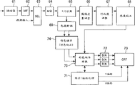
Fig. 9 shows an example of the variable process cellular construction of carrying out self-adaptive processing, specifically, be execution time/spatial manipulation with an example of the variable process cellular construction of the predicted value of the HD image of the sharpness of determining to have improvement according to the classification self-adaptive processing.
In variable process unit shown in Figure 9, when with the SD image from input media 11
kOffer output unit 12
mThe time, according to input media 11
kWith output unit 12
mType carry out the variable process suitably promote clearness.
Simple in order to illustrate, now supposition input 525i image (horizontally interlaced image with 525 horizontal line) or 262p image (image line by line with 262 horizontal line) are as the SD image, and output 525p image (image line by line with 525 horizontal line) is as the HD image.The frame frequency of the frame frequency of 262p SD image, the field frequency of 525iSD image and 525p HD image is identical, for example is 60Hz.Therefore, the frame frequency of 525i SD image is 30Hz.
Therefore, a frame of 262p SD image is corresponding to a frame of HD image, a frame corresponding to the HD image of 525i SD image.Pixel count on a horizontal line of 262p or 525i SD image is confirmed as for example 1: 2 with the ratio of the pixel count of 525p HD image.Therefore, 262p SD image and 525i SD image all double to be converted into the 525p HD image that sharpness improves by the quantity that makes vertical pixel and horizontal pixel, as shown in figure 10.In Figure 10, zero expression SD pixel, * expression HD pixel.
An exemplary of 525i image is the NTSC image (hereinafter referred to as " television image ") that forms from the television program of television broadcasting station transmission.An exemplary of 252p image is the game image of reading from game machine.
With reference to figure 9, be that the SD image that unit will promote clearness offers frame memory 211 with for example frame or field, and storing predetermined therein a period of time.
Prediction tapped forms circuit 212 and will form the intended pixel that sharpness is higher than the HD image of the SD image that is stored in the frame memory 211 again and be set at given pixel.The HD image is a virtual image, and reason is that in fact it be not present in the variable process unit.Then, prediction tapped forms the SD image of circuit 212 from be stored in frame memory 211 and selects some SD pixels near the pixel of given HD image in the space or on the time, thereby forms the prediction tapped that multiplies each other with predictive coefficient.
Prediction tapped forms circuit 212 and also is set at as prediction tapped according to the preference pattern (pattern) of the information of setting in register 218B (hereinafter referred to as " prediction tapped information ") with the SD pixel.
Specifically, form information according to prediction tapped, as shown in figure 10, prediction tapped forms the most approaching given pixel of circuit 212 chosen positions (has two pixels, i.e. P among Figure 10
33And P
34, will select P in this embodiment
33) the pixel of SD image, the position is at pixel P
33Upper and lower, a left side and four right nearest SD pixels be P
23, P
13, P
32And P
34, corresponding to P
33The SD pixel of former frame, corresponding to P
33The SD pixel of a back frame, i.e. seven pixels altogether.Prediction tapped forms the preference pattern (pattern) that circuit 212 is set at seven pixels the SD pixel that will use as prediction tapped.
Perhaps, form information according to prediction tapped, as shown in figure 10, prediction tapped forms circuit 212 and selects the pixel P of the SD image of close given pixel
33, the position is at pixel P
33Upper and lower, a left side and four right nearest SD pixels be P
23, P
43, P
32And P
34, corresponding to P
33The SD pixel of previous field, corresponding to P
33Back one SD pixel, promptly altogether seven pixels as will be as the preference pattern of the SD pixel of prediction tapped.
Perhaps, according to forming information according to prediction tapped, as shown in figure 10, prediction tapped forms circuit 212 and selects the pixel P of the SD image of close given pixel
33, the position is at pixel P
33Upper and lower, a left side and four right SD pixels every one be P
13, P
53, P
31And P
35, pixel P
33The SD pixel of front cross frame (or two), pixel P
33The SD pixel of two frames (or two) afterwards, promptly altogether seven pixels as will be as the preference pattern of the SD pixel of prediction tapped.
As mentioned above, prediction tapped forms circuit 212 and forms the information setting preference pattern according to prediction tapped, and the SD image selection from be stored in frame memory 211 will be as the SD pixel of the prediction tapped of given pixel.Afterwards, the prediction tapped of selected formation SD pixel is output to prediction and calculation circuit 216.
The SD pixel of electing prediction tapped as is not limited to above-mentioned preference pattern.In addition, although prediction tapped is formed by seven SD pixels in above-mentioned example, the SD pixel count that forms prediction tapped can form information according to prediction tapped and suitably set.
The class tap forms some SD pixels of SD image select time or the locus approaching given pixel of circuit 213 from be stored in frame memory 211, thereby forms the class tap that given pixel is divided into multiclass.
The class tap forms that circuit 213 sets according to the information (hereinafter referred to as " the class tap forms information ") among the register 218C of being set in will be as the preference pattern of the SD pixel of class tap.
Specifically, form information according to the class tap, as shown in figure 10, the class tap forms the pixel P of approaching given pixel of circuit 213 chosen positions
33, be positioned at pixel P
33Eight nearest SD pixel P of upper and lower, left and right, upper left, lower-left, upper right and bottom right
23, P
43, P
32, P
34, P
22, P
42, P
24And P
44, the SD pixel of the SD pixel of former frame and back one frame, promptly altogether 11 pixels as will be as the preference pattern of the SD pixel of class tap.
Perhaps, form information according to the class tap, as shown in figure 10, the class tap forms the pixel P of approaching given pixel of circuit 213 chosen positions
33, be positioned at pixel P
33Eight nearest SD pixel P of upper and lower, left and right, upper left, lower-left, upper right and bottom right
23, P
43, P
32, P
34, P
22, P
42, P
24And P
44, the SD pixel of previous field and back one SD pixel, promptly altogether 11 pixels as will be as the preference pattern of the SD pixel of class tap.
Perhaps, form information according to the class tap, as shown in figure 10, the class tap forms the pixel P of the SD image of approaching given pixel of circuit 213 chosen positions
33, be positioned at pixel P
33Eight of upper and lower, left and right, upper left, lower-left, upper right and bottom right every a SD pixel P
13, P
53, P
31, P
35, P
11, P
51, P
15And P
55, pixel P
33The SD pixel and the pixel P of front two frames (two)
33The SD pixel of next two frames (two), promptly altogether 11 pixels as will be as the preference pattern of the SD pixel of class tap.
As mentioned above, the class tap forms circuit 213 and forms the information setting preference pattern according to the class tap, and will be as the SD pixel of the class tap of given pixel according to the SD image selection of preference pattern from be stored in frame memory 211.Afterwards, the class tap is outputed to sorting circuit 214.
The SD pixel of electing the class tap as is not limited to above-mentioned preference pattern.In addition, although the class tap is formed by 11 SD pixels in above-mentioned example, the SD pixel count that forms the class tap can form information according to the class tap and suitably set.
214 pairs of given pixels of sorting circuit are classified, and will offer coefficient memory 215 as the address corresponding to the class sign indicating number of classification as a result.
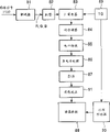
Figure 11 shows an example of sorting circuit 214 structures shown in Figure 9.
The class tap offer motion (motion) sorting circuit 221 and time/spatial classification circuit 222.
Classification of motions circuit 221 is classified to given pixel according to the motion of image according to the layout that forms the SD pixel of class tap in time domain.That is, as shown in figure 10, classification of motions circuit 221 utilizes altogether the i.e. pixel P of approaching given pixel of three pixels
33, previous field or frame SD pixel (or pixel P
33Former two or the SD pixel of two frames), SD pixel (or the pixel P of back or frame
33The SD pixel of two or two frames afterwards) given pixel is classified.
Specifically, classification of motions circuit 221 calculate in three SD images absolute difference between the time adjacent S D pixel and, and should and compare with predetermined threshold.Afterwards, classification of motions circuit 221 promptly 0 or 1 outputs to combiner circuit 223 according to comparative result with the class sign indicating number.
Hereinafter will be called " motion class sign indicating number " from the class sign indicating number of classification of motions circuit 221 outputs.
Time/all SD pixels that spatial classification circuit 222 utilization forms the class taps in the spatial domain of image or time domain according to grade distribute (level distribution) given pixel is classified.
Can use adaptive dynamic range coding (ADRC) method as time/sorting technique that adopts in the spatial classification circuit 222.
According to the ADRC method, the SD pixel that forms the class tap is carried out ADRC handle, according to the ADRC sign indicating number that obtains at last given pixel is classified.
In the ADRC method of K-position, detect the max pixel value MAX and the minimum pixel value MIN of the SD pixel that forms the class tap, DR=MAX-MIN is defined as local dynamic range DR.According to dynamic range DR, the SD pixel that forms the class tap is re-quantized to the K position.That is, from the pixel value of each SD pixel of forming the class tap, deduct minimum pixel value MIN, and will be by the value after deducting divided by DR/2
K(quantification).Afterwards, export the bit stream of the K-position pixel value of arranging with predefined procedure as the ADRC sign indicating number.Therefore, for example, handle according to ADRC, deduct minimum pixel value MIN from the pixel value of each SD pixel of forming the class tap, resulting value is divided by the mean value between max pixel value MAX and the minimum pixel value MIN.As a result, each pixel value is quantified as one.Afterwards, export the bit stream of the 1-position pixel value of arranging with predefined procedure as the ADRC sign indicating number.
Time/spatial classification circuit 222 can be directly be output as the class sign indicating number with the grade distribution pattern that forms the SD pixel of class tap.But, form by N SD pixel as the fruit tap, and if be that each SD pixel is distributed K position, the class number of codes is (2
N)
K, this is a big number of several exponentially ratios with position K.
Therefore, time/spatial classification circuit 222 is preferably in and the figure place of pixel value is carried out compression for example handles that ADRC classifies to given pixel after handling.Can carry out the processing of another kind of type ADRC, for example vector quantization is handled.
From time/the class sign indicating number hereinafter referred to as " time/spatial class sign indicating number " of spatial classification circuit 222 output.
Combiner circuit 223 will be represented from the motion class sign indicating number of classification of motions circuit 221 output (in this embodiment, a class sign indicating number) bit stream and expression from time/spatial classification circuit 222 output time/bit stream of spatial class sign indicating number arranges (merging) as a bit stream, thereby produce the final class sign indicating number of given pixel and it outputed in the coefficient memory 215.
In the embodiment shown in fig. 11, the class tap that forms the information among the register 218C that is arranged on offer classification of motions circuit 221, time/spatial classification circuit 222 and combiner circuit 223.This is in order to handle as the variation in the preference pattern of the SD pixel that is formed on the class tap in the class tap formation circuit 213.
Represented as dot-and-dash line among Figure 11, the motion class sign indicating number that obtains in classification of motions circuit 221 can be offered time/spatial classification circuit 222, time/spatial classification circuit 222 can change the SD pixel according to the motion class sign indicating number.
In this case, the class tap that will form by 11 SD pixels from the class tap form circuit 213 (Fig. 9) offer time/spatial classification circuit 222.Afterwards, time/spatial classification circuit 222 can be following the execution classification.When the motion class sign indicating number is 0, can use ten predetermined SD pixels in 11 SD pixels.When the motion class sign indicating number was 1, can use with the motion class sign indicating number was 10 SD pixels that 0 o'clock non-selected rest of pixels replaces above-mentioned ten intended pixels in the SD pixel.
When time/spatial classification circuit 222 divides time-like according to an ADRC processing execution, if use whole 11 SD pixels, then time/quantity of spatial class sign indicating number is (2
11)
1
On the other hand, only use ten SD pixels according to the motion class sign indicating number as mentioned above, then obtain at last time/the spatial class yardage is (2
10)
1Therefore, time/the spatial class yardage is significantly less than the class yardage of utilizing whole 11 SD pixels to classify and obtain.
But in this case, need expression to omit an information of the SD pixel that is used to classify.Therefore, time/the spatial class yardage is (2
10)
1* 2
1, promptly (2
11)
1This is just identical with the number that utilizes whole 11 SD pixels to classify to obtain.
As described below, again with reference to figure 9, coefficient memory 215 storages are handled a plurality of predictive coefficients that obtain by carrying out study.That is, coefficient memory 215 is formed by polytype district, the predictive coefficient of each district's storage respective type.The district that coefficient memory 215 will use according to message block (hereinafter referred to as " the coefficient information ") setting that is arranged among the register 218D.Coefficient memory 215 is provided by the predictive coefficient that is stored in corresponding in the address in the district of the class sign indicating number that is provided by sorting circuit 214 then, and this predictive coefficient is offered prediction and calculation circuit 216.
Then, prediction and calculation circuit 216 utilizes the predictive coefficient that is formed prediction tapped that circuit 212 provides and coefficient memory 215 and provided by prediction tapped to carry out the linear prediction that equation (1) expresses and calculates (long-pending and calculating).The pixel value that will obtain is at last exported to image reconstruction circuit 217 as the predicted value that sharpness is higher than the HD image of SD image then.
Then, image reconstruction circuit 217 forms each frame of 525pHD image by the predicted value that provides from prediction and calculation circuit 216, and exports them.
As mentioned above, with 262p SD image conversion be the HD image that the line number of every frame doubles.With the 525iSD image conversion is the HD image that every line number is doubled.Therefore, the horizontal sync frequencies of HD image is that the twice of SD image is so high.The conversion of horizontal sync frequencies is also carried out in image reconstruction circuit 217.
Although with the SD image conversion be 525p HD image in this embodiment, also can be converted into the HD image of another kind of form, for example 1050iHD image (horizontally interlaced image) or 1050pHD image (image line by line) with 1050 horizontal line with 1050 horizontal line.To be provided with according to the information (hereinafter referred to as " HD pixel format information ") that is stored in the register 218A from the form of the HD image of image reconstruction circuit 217 output.
That is, as shown in Figure 9, registers group 218 is formed by four register 218A-218D.As mentioned above,, HD pixel format information is set in register 218A, prediction tapped is set in register 218B forms information, the class tap is set in register 218C forms information, in register 218D, coefficient information is set according to control signal corresponding.Therefore, control signal comprises HD pixel format information, prediction tapped forms information, class tap formation information and coefficient information.Control signal produces (Fig. 2) in controller 30.
Specifically, controller 30 is according to the output unit 12 that pictorial data is provided through selector switch 23
mType determine HD pixel format information.Controller 30 is also according to the input media 11 that pictorial data is provided through selector switch 21
kType (in an embodiment, input media 11
kType represent input media 11
kWhether export 525i image or 262p image) and the output unit 12 of pictorial data is provided through selector switch 23
mType determine that prediction tapped forms information, the class tap forms information and coefficient information, so that can be to input media 11
kWith output unit 12
mCarry out predetermined process.
Improve the time/spatial manipulation of the SD image definition of finishing in the variable process shown in Figure 9 unit below with reference to the flow chart description of Figure 12.
Specify the input media 11 of input imagery by remote controller 5 (Fig. 1) as the user
kOutput unit 12 with output image
mThe time, controller 30 control selector switchs 21 and 23 are selected respectively and are specified input media 11
kThe terminal 2 that connects
kWith with specify output unit 12
mThe terminal 3 that connects
mAfterwards, select from input media 11 by selector switch 21
kThe pictorial data of output also offers integrated processor shown in Figure 2 27 (variable process group 28 and common process group 29), selects from the pictorial data of integrated processor 27 outputs and offers output unit 12 by selector switch 23
m
In this embodiment, input media 11
kWith output unit 12
mSelect by user instruction.Perhaps, can be in advance at the terminal 2 of selector switch 21
kTerminal 3 with selector switch 23
mIn corresponding input media 11 is set
kWith output unit 12
mPerhaps, controller 30 can be according to the combination of the input media type that is connected with selector switch 21 with best input media of the output unit type selecting that is connected with selector switch 23 and best output unit.
From the input media of selecting by selector switch 21 11
kThe SD image that receives is that unit provides and is stored in the frame memory 211 with frame or field again.
Simultaneously, controller 30 (Fig. 1) is according to input media 11
kType and output unit 12
mType produce control signal corresponding, and they are offered registers group 218.Therefore, according to control signal HD pixel format information, prediction tapped formation information, class tap formation information and coefficient information are set in register 218A, 218B, 218C and the 218D of registers group 218 respectively.
In this embodiment, be 525p HD image with 525i or 262p SD image conversion.Therefore, in HD pixel format information, the 525p image is set.In prediction tapped formation information, being provided with 525i or 262p SD image conversion is the preference pattern of the formation optimum prediction tap of 525p HD image.In class tap formation information, being provided with 525i or 262p SD image conversion is the preference pattern of the formation optimum kind tap of 525p HD image.In coefficient information, expression storage be set be the information of one group of coefficient memory 215 of the optimum prediction coefficient of 525p HD image with 525i or 262p SD image conversion.
Then, in step S1, bring up in the pixel that surpasses the HD image that is stored in the SD image in the frame memory 211 given pixel is set forming sharpness.As mentioned above, the HD image is a virtual image, and reason is that in fact it be not present in the variable process unit.Prediction tapped forms circuit 212 and utilizes the pixel that is stored in the SD image in the frame memory 211 to form the prediction tapped of given pixel.In addition, in step S1, the class tap forms circuit 213 and utilizes the pixel that is stored in the SD image in the frame memory 211 to form the class tap of given pixel.Then, prediction tapped is provided for prediction and calculation circuit 216, provides the class tap for sorting circuit 214 simultaneously.
Prediction tapped forms circuit 212 and forms information according to the prediction tapped that is arranged among the register 218B, is provided with being used as the preference pattern of the SD pixel of prediction tapped, selects the SD pixel according to preference pattern, thereby forms prediction tapped.The class tap forms circuit 213 and forms information according to the class tap that is arranged among the register 218C, and setting will be used as the preference pattern of the SD pixel of class tap, and selects the SD pixel according to preference pattern, thereby forms the class tap.
Then, in step S2, sorting circuit 214 is classified to given pixel according to the class tap that the class tap forms circuit 213 and provides, and will offer coefficient memory 215 as the address corresponding to the class sign indicating number of class as a result.
Then, in step S3, coefficient memory 215 is read the predictive coefficient of storing in the address of the class representation that sorting circuit 214 provides, and these coefficients are offered prediction and calculation circuit 216.
In step S4, the predictive coefficient that prediction and calculation circuit 216 utilizes prediction tapped to form prediction tapped that circuit 212 provides and coefficient memory 215 to be provided is carried out the linear prediction that equation (1) expresses and is calculated, and the pixel value that will obtain at last offers image reconstruction circuit 217 as the predicted value of given pixel.
Then, in step S5, image reconstruction circuit 217 for example determines whether a frame of predicted value obtains from prediction and calculation circuit 216.If whether the output of step S5, handle going back to step S1, in the pixel of the respective frame that forms the HD image, new given pixel is set, and the processing of repeating step S1 to S5.
If find in step S5, to obtain a frame of predicted value, handle and proceed to step S6, in step S6,217 reconstruct of image reconstruction circuit are corresponding to a frame of the HD image (525p HD image) of this frame of predicted value.Handle then and get back to step S1, repeat from the processing of step S1 the next frame of HD image is similar.
Figure 13 shows the block diagram of facility for study that an example carry out to determine to be stored in the learning process of the predictive coefficient in the coefficient memory 215 of variable process unit shown in Figure 9.
HD image (hereinafter referred to as " keeper's image ") as administrator data for example is that unit offers frame memory 231 with the frame, and frame memory 231 is storage administrator's image again.
In this embodiment, because the HD image that will obtain is the 525p image, therefore the 525p image is used as keeper's image in variable process shown in Figure 9 unit.
It for example is that unit is stored in the keeper's image in the frame memory 231 with the frame that decimation filter 232 is read.Decimation filter 232 is then carried out low-pass filtering (LPF) to reduce the frequency bandwidth of keeper's image, also reduces pixel count.Therefore, decimation filter 232 reduces the sharpness of keeper's image so that produce the SD image (this paper is called " beginner's image ") that is used as beginner's data, and the SD image is offered frame memory 233.
In this embodiment promptly, in variable process unit shown in Figure 9,525p HD image obtains from 525i or 262p SD image.In addition, the pixel count of 525p HD image is the twice of 525i or 262p SD image on vertical and horizontal direction.
Therefore, in order to produce beginner's image (525i or 262pSD image) from keeper's image (525p HD image), decimation filter 232 is at first carried out LPF and is handled (semi-band filtering in this embodiment) so that frequency band is reduced to half.
Decimation filter 232 is also whenever selected alternately to the pixel on the horizontal direction that is arranged in the image that LPF handled, thereby pixel count is reduced to half.Afterwards, the horizontal line of each frame of 232 pairs of keeper's images of decimation filter is whenever selected alternately, thereby the number of horizontal line is reduced to half.As a result, can produce 262p SD image as beginner's image.
Perhaps, decimation filter 232 can be selected the even number line of each odd-numbered frame of keeper's image, also selects the odd-numbered line of each even frame, thereby number of horizontal lines is reduced to half.As a result, can produce 525i SD image as beginner's image.
Decimation filter 232 is determined visual type, i.e. 252pSD image or 525i SD image according to the information (hereinafter referred to as " beginner's pixel format information ") that is arranged among the register 240A.
Frame memory 233 is that unit stores with frame or field for example with beginner's image of decimation filter 232 outputs again.
The pixel (hereinafter referred to as " keeper's pixel ") that prediction tapped formation circuit 234 will be stored in the formation keeper image in the frame memory 231 again is set to given pixel.Prediction tapped forms circuit 234 and reads the pixel (hereinafter referred to as " beginner's pixel ") of some beginner's images of space or upward close given pixel location of time then from frame memory 233, and forms prediction tapped so that multiply each other with predictive coefficient.
Promptly, as forming circuit 212 at the prediction tapped shown in Fig. 9, prediction tapped forms the preference pattern of beginner's pixel that circuit 234 will use as prediction tapped according to information (hereinafter referred to as " prediction tapped formation the information ") setting that is arranged among the register 240B.Afterwards, according to preference pattern, prediction tapped forms the beginner image selection of circuit 234 from be stored in frame memory 233 will be as beginner's pixel of the prediction tapped of given pixel.Then prediction tapped is outputed to normal equation adding circuit 237.
Simultaneously, the class tap forms circuit 235 and is positioned at some beginner's pixels near given pixel and the class tap that is formed for classifying from 233 readout times of frame memory or space.
Specifically, as forming circuit 213 in the class tap shown in Fig. 9, the class tap forms circuit 235 and is provided with and will be used as the preference pattern of beginner's pixel of class tap according to the information (hereinafter referred to as " the class tap forms information ") that is arranged among the register 240C.Afterwards, according to preference pattern, the class tap forms beginner's pixel that the beginner image selection of circuit 235 from be stored in frame memory 233 will be used for the class tap of given pixel.Then the class tap is outputed to sorting circuit 236.
The structure of sorting circuit 236 and sorting circuit shown in Figure 9 214 are similar.Sorting circuit 236 is classified to given pixel according to the class tap that forms circuit 235 from the class tap and provide, and will offer normal equation adding circuit 237 corresponding to the class sign indicating number of class as a result.
The class tap formation information that is arranged among the register 240C is provided for sorting circuit 236.Its reason is with identical with reference to sorting circuit 214 described reasons shown in Figure 9.
Normal equation adding circuit 237 is read the keeper's pixel that is provided with as given pixel from frame memory 231, and keeper's pixel and beginner's pixel that prediction tapped forms the formation prediction tapped that circuit 234 provides are calculated.
Specifically, the product (X of beginner's pixel is provided each component of the matrix A of equation (12) corresponding to the prediction tapped (beginner's pixel) of every class of the class sign indicating number that provides from sorting circuit 236 237 utilizations of normal equation adding circuit
InX
Im) and summation (∑).
Normal equation adding circuit 237 also utilizes prediction tapped (beginner's pixel) and the given pixel (keeper's pixel) of every class of the class sign indicating number that provides corresponding to sorting circuit 236 is carried out the product (X of beginner's pixel and given pixel (keeper's pixel) in each component of the vector v of equation (12)
InY
i) and summation (∑).
All keeper's pixels that normal equation adding circuit 237 usefulness are stored in the frame memory 231 are carried out aforementioned calculation as given pixel, thereby are formulated the normal equation of equation (12) expression of every class.
Predictive coefficient determines that circuit 238 determines the predictive coefficient of every class by solve the normal equation that is formulated in normal equation adding circuit 237, and predictive coefficient is offered predictive coefficient corresponding to the address of every class of storer 239.
According to number of images (frame number) or the image content prepared as keeper's image, have some classes of determining that the required normal equation of predictive coefficient can not calculate with formula.In this case, predictive coefficient determines that circuit 238 exports default predictive coefficient for this kind.
Storer 239 storages are determined the predictive coefficient that circuit 238 provides from predictive coefficient.That is, storer 239 is formed by a plurality of districts and the corresponding predictive coefficient of storage in each district.Storer 239 bases are arranged on the district that information (hereinafter referred to as " the coefficient information ") setting among the register 240D will be used, and predictive coefficient is determined that the predictive coefficient that circuit 238 provides is stored in the address of the class sign indicating number that provides corresponding to sorting circuit 214.
Registers group 240 storage is used to be provided with decimation filter 232, prediction tapped and forms the information that circuit 234, class tap form the function of circuit 235 and storer 239.
Specifically, in the embodiment shown in fig. 13, registers group 240 is formed by four register 240A to 240D.According to the control signal of coming self-controller 241, beginner's pixel format information is set in register 240A, prediction tapped is set in register 240B forms information, the class tap is set in register 240C forms information, in register 240D, coefficient information is set.Therefore, control signal comprises beginner's pixel format information, and prediction tapped forms information, and the class tap forms information and coefficient information.
Controller 241 is for example operated by the system designer.According to designer's operation, controller 241 determines to be arranged on the beginner's pixel format information in the registers group 240, and prediction tapped forms information, and the class tap forms information and coefficient information.Controller 241 produces control signal corresponding and they is offered registers group 240 then.
The study of the predictive coefficient of carrying out below with reference to the flow chart description of Figure 14 facility for study shown in Figure 13 is handled.
Controller 241 produces control signal, and they are offered registers group 240.Therefore, based on beginner's pixel format information of control signal corresponding, prediction tapped forms information, and the class tap forms information and coefficient information is set at respectively in the middle of register 240A, 240B, the 240C and 240.
Then, in step S21, keeper's image of preparing for the study predictive coefficient provides and is stored in the frame memory 231.In step S22, the array variable A[c of the matrix A of 237 pairs of every classes of storage of normal equation adding circuit] and store the array variable v[c of vector v in the equation (12)] be initialized as 0.
Then, in step S23, decimation filter 232 produces 525i or 262p SD image as beginner's image by the keeper image that processing is stored in the frame memory 231 according to the beginner's pixel format information among the register 240A of being arranged on.That is, keeper's image that 232 pairs of decimation filters are stored in the frame memory 231 carries out the LPF processing, reduces the pixel count of the keeper's image after LPF handles then, thereby produces the beginner's image with lower resolution.Beginner's image is provided again and is stored in the frame memory 233.
In step S24, in the keeper's pixel in being stored in frame memory 231 given pixel is set.Prediction tapped forms circuit 234 according to beginner's pixel of selecting to be stored in corresponding to the preference pattern that is arranged on the prediction tapped formation information among the register 240B in the frame memory 233, thereby forms the prediction tapped of given pixel.Simultaneously, the class tap forms circuit 235 according to beginner's pixel of selecting to be stored in corresponding to the preference pattern that is arranged on the class tap formation information among the register 240C in the frame memory 233, thereby forms the class tap of given pixel.Afterwards, prediction tapped is offered normal equation adding circuit 237, simultaneously the class tap is offered sorting circuit 236.
In step S25, sorting circuit 236 is classified to given pixel according to the class tap that forms circuit 235 from the class tap and provide, and will offer normal equation adding circuit 237 corresponding to the class sign indicating number of class as a result.
After this, in step S26, normal equation adding circuit 237 is read keeper's pixel (given pixel) from frame memory 231, utilizes array variable A[c according to each the class C that provides from sorting circuit 236] and v[c] given pixel (keeper's pixel) addition of vector v the prediction tapped (beginner's pixel) of above-mentioned matrix A and the equation (12) carried out.
Determine whether in step S27 that then keeper's pixel that all formation are stored in the keeper's image in the frame memory 231 obtains handling as given pixel.If the result of step S27 handles and returns step S24 for not.In this case, one of them keeper's pixel is set to new given pixel, and the processing of repeating step S24 to S27.
Obtain handling if in step S27, find all keeper's pixels, promptly in normal equation adding circuit 237, be formulated the normal equation of all classes, handle proceeding to step S28 as given pixel.In step S28, predictive coefficient determines that circuit 238 determines the predictive coefficient of each class by solving corresponding normal equation, and they are offered the address of the respective class of storer 239.
Storer 239 selects to be arranged on that district corresponding to coefficient information among the register 240D, will store the predictive coefficient of determining the respective class that circuit 238 provides from predictive coefficient in each address in institute constituency.Finishing study then handles.
Carrying out study shown in Figure 14 when the district of each storer 239 changes handles.In other words, carrying out study according to the type of predictive coefficient handles.
In the aforementioned embodiment, two types predictive coefficient is arranged, and promptly being suitable for 525i SD image conversion is the predictive coefficient (hereinafter referred to as " 525i predictive coefficient ") of 525p HD image and to be suitable for the 262SD image conversion be the predictive coefficient (hereinafter referred to as " 262p predictive coefficient ") of 525p HD image.
According to facility for study shown in Figure 13,, obtain 525i predictive coefficient and 262p predictive coefficient by changing administrator data (keeper's image) and beginner's data (beginner's image).Perhaps, can obtain in time domain, changing pixel count (frame frequency or field frequency) or change the predictive coefficient of image aspect of pixel or predictive coefficient that can noise reduction.525i predictive coefficient and 262p predictive coefficient have the function that increases the function of pixel count and improve sharpness in spatial domain.Therefore, can obtain having the predictive coefficient of two kinds of functions.In other words, utilize this predictive coefficient, can realize two types of processing simultaneously.Specifically, at first reduce the sharpness of keeper's image, in time/spatial domain, reduced the pixel count of final keeper's image then, thereby formed beginner's image.Utilize this beginner's image, carry out study and handle.As a result, the predictive coefficient of determining to improve sharpness and being increased in pixel count in time/spatial domain.
As mentioned above, carry out study, can obtain carrying out the predictive coefficient of dissimilar variable process by the combination that utilizes various types of administrator data and beginner's data.Then, the variable process group 28 (Fig. 2) of integrated processor 27 can utilize this predictive coefficient to carry out various types of variable process.
Common process group 29 shown in Figure 2 is carried out common process previously discussed.This common process also can realize by the classification self-adaptive processing.Therefore, can make up each common process unit of common process group 29 with variable process unit shown in Figure 9 similarly.
If variable process and common process all utilize the classification self-adaptive processing finish, then can with variable process shown in Figure 9 unit cascaded to corresponding common process unit so that finish variable process and common process respectively.Perhaps, processing unit shown in Figure 9 can be used for variable process unit and common process unit.That is, predictive coefficient is learnt to utilize this predictive coefficient once to carry out variable process and common process, carry out variable process and common process simultaneously.
Describe below with integrated processing block 1 shown in Figure 1 and input media, output unit and memory storage that integrated processor 27 shown in Figure 2 is connected in common process and the variable process carried out.
As mentioned above, integrated processing block 1 can with the device that only forms (special device) by proprietary part with resemble conventional apparatus three parts are arranged is that the device (common unit) that proprietary part, the part of carrying out common process and the part of carrying out variable process form is connected.
Figure 15 shows an example of video camera (standard set-up) structure as input media.
Charge-coupled device (CCD) 41 receives light and carries out light-to-current inversion from object, thus the final electric signal of the light quantity that receives to the 42 output expressions of sampling hold circuit (S/H) circuit.S/H circuit 42 regularly will output to it automatic gain control (AGC) circuit 43 from electric signal sampling and the maintenance of CCD41 then with predetermined.The gain (AGC processing) that agc circuit 43 is regulated from the output of S/H circuit 42 offers modulus (A/D) change-over circuit 44 with analog picture signal.44 pairs of analog picture signals from agc circuit 43 outputs of A/D change-over circuit carry out the A/D conversion, and the digital image signal that will finally obtain outputs to defect correction circuit 45.The pictorial data that 45 pairs of A/D change-over circuits 44 of defect correction circuit provide is carried out defect correction and is handled.In video camera, some pixels can be owing to the defective of CCD41 is lost.In this treatment for correcting, can proofread and correct this defective.The pictorial data that will finally obtain outputs to white balance (WB) circuit 46 then.WB circuit 46 is regulated the level (level) (WB processing) that forms from each component for example red (R) of the pictorial data of defect correction circuit 45 outputs, green (G) and blue (B) component.As a result, the level ratio of each component can be a predetermined value.Then, the image that obtains is at last outputed to checking gamma circuit 47.The pictorial data that 47 pairs of checking gamma circuits receive from WB circuit 46 are carried out γ and are proofreaied and correct, and will obtain data at last and output to pixel interpolation circuit 48.Pixel interpolation circuit 48 inserts R, G and B component on demand in the pixel of the pictorial data that formation checking gamma circuit 47 provides.
That is, in the embodiment shown in fig. 15, video camera is the single part type, places color filter mirror (not shown) before CCD41.Therefore, only comprise one type component in R component, G component and the B component from the pixel of the formation picture intelligence of CCD41.Specifically, comprise that the pixel of R component does not comprise G and B component, comprise that the pixel of G component does not comprise R and B component, comprise that the pixel of B component does not comprise R and G component.Therefore, the component of pixel interpolation circuit 48 definite which kind of type has been lost, and inserts the component of losing, and the picture intelligence that obtains is at last outputed to colour matrix change-over circuit 49.
If video camera is three component types, then do not need pixel interpolation circuit 48.
R, G and the B component of 49 pairs of pictorial data of colour matrix change-over circuit carry out the colour matrix conversion process, and for example export Y, R-Y and B-Y pictorial data.Necessary, the imagery data recording that record cell 50 provides colour matrix change-over circuit 49 is on recording medium, for example on the videotape.
Figure 16 shows the topology example of the video camera (special device) as input media.Element same as shown in Figure 15 represents that with identical reference number its explanation is omitted.
Under the situation of not carrying out the defect correction circuit 45 of variable process or common process, checking gamma circuit 47, pixel interpolation circuit 48 and colour matrix change-over circuit 49, form video camera shown in Figure 16.
Therefore, in special device video camera shown in Figure 16, do not carry out defect correction processing, γ treatment for correcting, pixel interpolation processing and the colour matrix conversion process in conventional equipment, carried out.
That is, because common process and variable process are carried out by integrated processor 27, therefore not needing provides the piece of carrying out common process or variable process for video camera (special device).
Figure 17 shows processing and common process of carrying out and the relation of carrying out between the variable process in integrated processor 27 in video camera (common unit).
In video camera 40A (common unit), carry out that AGC handles, white balance (WB) is handled, reduce noise reduction process, defect correction processing, the pixel interpolation processing of noise in the pictorial data, the correction of frequency characteristic processing that is used for corrected image data frequency characteristic, γ treatment for correcting, colour matrix conversion process, pictorial data be converted to the NTSC encoding process of NTSC data etc.In Figure 17 (also being) at Figure 20,24,26 and 38, below video camera 40A, show the operation that video camera 40A carries out, carry out the operation in the bracket when needing.
In the operation that video camera 40A carries out, noise reduction process and NTSC encoding process are common and whether input media is irrelevant for video camera 40A, are common process therefore.On the other hand, defect correction processing, pixel interpolation processing, correction of frequency characteristic are handled, whether the γ treatment for correcting is that video camera 40A is relevant with input media all with the colour matrix conversion process, are variable process therefore.
When video camera 40A (common unit) is connected with integrated processing block 1 (Fig. 1) so that when the pictorial data of video camera 40A output offered integrated processor 27 (Fig. 2), integrated processor 27 is carried out following processing.Variable process group 28 is carried out defect correction processing, pixel interpolation processing, correction of frequency characteristic processing, γ treatment for correcting and colour matrix conversion process to pictorial data on demand, and all these processing all are variable process.Common process group 29 is carried out noise reduction process and NTSC encoding process on demand, and these processing all are common process.
That is, integrated processor 27 is carried out variable process and the common process that video camera 40A is not carried out.Perhaps, even in the variable process and common process that can be carried out by video camera 40A, if integrated processor 27 can more effectively be carried out these processing than video camera 40A, it also can carry out corresponding processing.
Figure 18 is the block diagram of an example as the CRT monitor (conventional equipment) of output unit.
Picture quality regulating circuit 66 is by increasing pre-shooting (pre-shooting) and crossing and take the luminance signal carries out image quality from y/c separation circuit 65, and as aperture correction, and the luminance signal after will regulating offers contrast adjustment circuit 67.Contrast adjustment circuit 67 is regulated from the contrast of the luminance signal of picture quality regulating circuit 66 outputs, and the luminance signal that the result obtains is offered brightness correction circuit 68.Brightness correction circuit 68 is carried out gamma correction and is handled, as reads from the DC component of the luminance signal of contrast adjustment circuit 67 outputs, and the luminance signal that the result obtains is offered colour matrix change-over circuit 70.
Simultaneously, the carrier chrominance signal (C) of chrominance demodulation circuit 69 separating color train of impulses (burst signal) signal and y/c separation circuit 65 outputs, and based on R-Y signal and the B-Y signal of chrominance pulse string signal demodulation from carrier chrominance signal.Chrominance demodulation circuit 69 offers colour matrix change-over circuit 70 to R-Y signal and B-Y signal through adjustment of color matrix 74 afterwards.Adjustment of color matrix 74 is carried out colour correction according to user's operation to the output of chrominance demodulation circuit 69.
70 pairs of luminance signals of colour matrix change-over circuit (Y) and carry out the colour matrix conversion to be converted into R, the view data that G and B component constitute from the R-Y signal of chrominance demodulation circuit 69 and B-Y signal from brightness correction circuit 68.With R, G and B component offer digital-to-analogue (D/A) converter 72 then.Colour matrix change-over circuit 70 uses predetermined synchronizing signal when carrying out the colour matrix conversion process, and this synchronizing signal is offered synchronously/deflection processing circuit 71.Synchronously/deflection processing circuit 71 is based on produce vertical deflection signal (V defection signal) and the horizontal deflection signal (H defection signal) that drives CRT 73 from the synchronizing signal of colour matrix change-over circuit 70.V defection signal and H defection signal are offered the deflection coil (not shown) of CRT 73, thereby drive CRT 73.
Simultaneously, 72 couples of R from the digital signal of colour matrix change-over circuit 70 of D/A converting unit, G, B component carry out the D/A conversion and the R of simulating signal that the result is obtained, G, and the B component offers CRT 73.Then, on CRT 73, show corresponding to R G, the image of B component.
In Figure 18, can there be A/D change-over circuit 64 and D/A converter 72 to form CRT monitor (conventional equipment).
Figure 19 represents the structural drawing of an example as the CRT monitor (special device) of output unit.Element same as shown in Figure 18 represents that with the same reference sequence number its explanation is omitted.
CRT monitor shown in Figure 19 has formed, but does not use picture quality regulating circuit 66, contrast adjustment circuit 67, brightness correction circuit 68, colour matrix change-over circuit 70 and the adjustment of color circuit 74 of carrying out common process or variable process.
Therefore, in CRT monitor (special device) shown in Figure 19, do not carry out picture quality adjusting processing, contrast adjustment processing, gamma correction processing, colour matrix conversion process and the colour correction in CRT monitor (conventional equipment), carried out and handle.
That is, because above-mentioned common process and variable process are carried out by integrated processor 27, CRT monitor (special device) does not form the piece of carrying out these processing.
Figure 20 represents operation and the common process of integrated processor 27 execution and the relation between the variable process that CRT monitor (conventional equipment) is carried out.
In CRT monitor (conventional equipment) 60A, carrying out AGC handles, the NTSC view data is converted to R, G, the NTSC decoding processing of the view data that the B component constitutes, noise reduction process, correction of frequency characteristic is handled, pixel count is converted to the pixel count conversion process of the sharpness that is suitable for CRT monitor 60A, gamma correction is handled (corresponding to the processing of 68 execution of the brightness correction circuit among Figure 18), colour matrix conversion process (processing of carrying out corresponding to the colour matrix change-over circuit 70 of Figure 18) and the colour correction that the chrominance component of view data is adjusted to the characteristic that is suitable for CRT monitor 60A handled (processing of carrying out corresponding to adjustment of color circuit shown in Figure 180 74).
In Figure 20, in the operation of being carried out by CRT monitor 60A, whether noise reduction process and NTSC decoding processing and output unit are that CRT monitor 60A has nothing to do, from but common process.Correction of frequency characteristic processing, pixel count conversion process, gamma correction are handled, whether the colour matrix conversion process is that CRT monitor 60A is relevant with the colour correction processing with output unit, from but variable process.
When CRT monitor 60A is connected in integrated processing block 1 (Fig. 1) as output unit when view data being offered CRT monitor 60A, the processing below integrated processor 27 (Fig. 2) is carried out.Variable process group 28 is carried out correction of frequency characteristic processing, pixel count conversion process, gamma correction processing, colour matrix conversion process and colour correction on demand and is handled, and all these is a variable process.Common process group 29 is carried out noise reduction process and NTSC decoding processing on demand, and these are common process.
That is, integrated processor 27 is carried out common process and the variable process that CRT monitor 60A is not carried out.Perhaps even in the common process and variable process that can be carried out by CRT monitor 60A, if integrated processor 27 comparable CRT monitor 60A more effectively carry out, then integrated processor 27 can be carried out corresponding processing.
Figure 21 illustrates video camera (special device) 40B that is chosen as input media and is chosen as CRT monitor (special device) 60B of the output unit that is connected in integrated processing block 1.Video camera 40B can form as shown in figure 16 and CRT monitor 60B can form as shown in figure 19.
To offer integrated processor 27 from the view data of video camera 40B output.29 pairs of view data of the common process group of integrated processor 27 are carried out noise reduction process.28 pairs of view data of variable process group are carried out variable process, as defect correction, γ correction, gamma correction, pixel count conversion, line number conversion, frame number conversion, frequency characteristic conversion, color conversion and colour matrix conversion, to be suitable for video camera 40B and CRT monitor 60B.The view data that the result is obtained offers CRT monitor 60B then.
Based on the scan method of the pixel count of the CCD of video camera 40B, CRT monitor 60B (for example, NTSC method, PAL method or method line by line), sharpness (for example, image is SD or HD image) etc. carry out pixel count conversion process, line number conversion process, frame number conversion process, frequency characteristic conversion process, make suitably to be presented on the CRT monitor 60B from the image of video camera 40B output.
In the embodiment shown in Figure 21, defect correction processing, pixel count conversion process, line number conversion process, frame number conversion process are included in time/spatial manipulation.γ treatment for correcting and gamma correction are handled and are included in the gray level processing, and it reflects image gray levels.The frequency characteristic conversion process is included in the frequency quantity processing.During being included in and handling between component, colour correction processing and colour matrix conversion process form the R of view data, G, B component with processing.Handle by above-mentioned classification self-adaptive processing between time/spatial manipulation, gray level processing, frequency quantity processing and component and carry out.
Like this, carry out time/spatial manipulation of being used for defect correction and handling independently by learning corresponding predictive coefficient, be used for that the time/spatial manipulation of pixel count conversion process, line number conversion process, frame number conversion process is handled, is used for to the gray level that γ proofreaies and correct and gamma correction is handled, the frequency quantity that is used for the frequency characteristic conversion process is handled and be used for handling between the component of color conversion process and colour matrix conversion process.Perhaps, the predictive coefficient of all processing can be learnt to carry out, and above-mentioned processing can be once carried out.
Handle according to frequency quantity, the frequency characteristic of image is regulated according to the predictive coefficient that uses in the classification self-adaptive processing.In this case, controller 30 (Fig. 2) can be determined frequency characteristic through the operation of telepilot 5 (Fig. 1) by for example user.Perhaps, controller 30 can be operated the deduction frequency characteristic based on the user who carries out through telepilot 5, automatically performs frequency quantity afterwards and handles, and makes the frequency characteristic of customer requirements not need user's executable operations just can obtain.
In Figure 21, handle the processing of carrying out corresponding to defect correction circuit shown in Figure 15 45 as the defect correction of time/spatial manipulation, the processing that the γ treatment for correcting of handling as gray level is carried out corresponding to checking gamma circuit shown in Figure 15 47.The gamma correction of handling as gray level is handled the processing of carrying out corresponding to WB circuit 46 shown in Figure 15 and contrast adjustment circuit 67 shown in Figure 180.As the processing of the colour matrix conversion process of handling between component corresponding to colour matrix conversion process shown in Figure 15 49 execution.
In Figure 21, in conventional equipment, do not carry out as pixel count conversion process, line number conversion process and the frame number conversion process of time/spatial manipulation and as the frequency characteristic conversion process of frequency quantity conversion process.Integrated processor 27 is carried out the processing of the above-mentioned type of not carrying out effectively in conventional equipment.More specifically say, when video camera 40B output NTSC image and when CRT monitor 60B shows the PAL image, integrated processor 27 as time/spatial manipulation carries out the line number conversion process and the frame number conversion process is the PAL image that will show on CRT monitor 60B with the NTSC image transitions that video camera 40B is exported.When video camera 40B output SD image and CRT monitor 60B show the HD image, integrated processor 27 as time/spatial manipulation carries out pixel count conversion process and line number conversion process with from the SD image transitions of the video camera 40B output HD image for showing at CRT monitor 60B.
Figure 22 represents the structure of an example as the LCD monitor (conventional equipment) of output unit.
(VBS) offers demoder 81 the NTSC composite picture signal.Demoder 81 is converted to picture signal by execution NTSC decoding and has R then, the picture signal of G and B component, and provide it to A/D change-over circuit 82.82 pairs of A/D change-over circuits are carried out the A/D conversion being digital signal with analog-converted from the picture signals of demoder 82.Then Digital Image Data is offered horizontal register (H register) 83.A horizontal line of the pixel value of the view data that provides from A/D change-over circuit 82 is provided based on the timing signal that provides from timing generator (TG) 89 horizontal register 83 successively.When a horizontal line (pixel value) of view data was latched in the horizontal register 83, line storage 84 was read whole image data from horizontal register 83 and is also stored there.Level shifting circuit 85 is read the horizontal line of the view data that is stored in the line storage 84 and the level (level conversion) of conversion image data then, provides it to many level (gray level) circuit 86.Multi-level circuit 86 produces multi-level signal voltage (processing of many level) and provides it to D/A change-over circuit 87 based on the view data from level shifting circuit 85 outputs.D/A change-over circuit 87 is converted to analog signal voltage to the digital signal voltage corresponding to the view data of exporting from multi-level circuit 86, and provides it to masking circuit 91.The output of 91 pairs of D/A change-over circuits 87 of masking circuit is afterwards carried out colour correction and the signal that the result obtains is offered liquid crystal panel 88.
Simultaneously, timing generator 89 offers horizontal register 83 and scanner driver 90 to the timing signal that produces.Scanner driver 90 drives liquid crystal panel 88 according to the timing signal from timing generator 89.As a result, the image of the signal voltage that provides corresponding to D/A change-over circuit 87 is presented on the liquid crystal panel 88.
Figure 23 represents the structure of an example as the LCD monitor (special device) of output unit.Represent with identical reference number that with element components identical shown in Figure 22 its explanation is omitted.
Therefore, in LCD monitor shown in Figure 23, do not carry out NTSC decoding processing, the level conversion in LCD monitor (conventional equipment), carried out and handle and the processing of many level.
That is,, can form the LCD monitor of the piece of not carrying out common process or variable process because this common process and variable process are carried out by integrated processor 27.
Figure 24 represents operation and the common process of integrated processor 27 execution and the relation between the variable process that LCD monitor (conventional equipment) is carried out.
In LCD monitor (conventional equipment) 80A, carry out AGC processing, NTSC decoding processing, γ treatment for correcting, colour matrix conversion process, colour correction processing, black-level correction processing, shadow correction processing, pixel count conversion process, correction of frequency characteristic processing etc.
In Figure 24, in the operation that LCD monitor 80A carries out, the NTSC decoding processing is common and whether output unit is irrelevant for LCD monitor 80A, is common process therefore.On the contrary, whether γ treatment for correcting, colour matrix conversion process, colour correction processing, black-level correction processing, shadow correction processing, pixel count conversion process, correction of frequency characteristic are handled with output unit is that LCD monitor 80A is relevant, is variable process therefore.
When LCD monitor 80A is connected in integrated processing block 1 so that view data is offered LCD monitor 80A as output unit, the processing below integrated processor 27 is carried out.Variable process group 28 is carried out variable process on demand, as γ correction, colour matrix conversion, colour correction, black-level correction, shadow correction, pixel count conversion and correction of frequency characteristic.Common process group 29 is carried out the NTSC decoding processing on demand.
That is, integrated processor 27 execution can not be by the variable process and the common process of LCD monitor 80A execution.Perhaps, even in the variable process and common process that can be carried out by LCD monitor 80A, if integrated processor 27 can more effectively be carried out processing than LCD monitor 80A, then integrated processor 27 can be carried out corresponding processing.
Figure 25 represents to be chosen as video camera (special device) 40B of input media and is chosen as LCD monitor (special device) 80B of the output unit that is connected in integrated processing block 1.Video camera 40B can form as shown in figure 16, and LCD monitor 80B can form as shown in figure 23.
View data from video camera 40B output is offered integrated processor 27.29 pairs of view data of the common process group of integrated processor 27 are carried out noise reduction process.28 pairs of view data of variable process group are carried out variable process, as defect correction, γ correction, gray level correction, black-level correction, shade, colour matrix conversion, colour correction, pixel count conversion, line number conversion and frequency characteristic conversion, to be suitable for video camera 40B and LCD monitor 80B.The view data that the result obtains is provided for LCD monitor 80B.
More specifically say, pixel count conversion process, line number conversion process and frequency characteristic conversion process are based on the graphics standard of the pixel count of the CCD of video camera 40B, LCD monitor 80B (for example, VGA or SXGA) and the pulse-length modulation (PWM) in the liquid crystal panel of LCD monitor 80B, used and polar inversion method carry out, make can suitably be presented on the LCD monitor 80B from the image of video camera 40B output.
In Figure 25, defect correction processing, pixel count conversion process and line number conversion process are included in time/spatial manipulation.γ treatment for correcting, gray level correction are handled, black-level correction is handled and the shadow correction processing is included in the gray level processing.During colour correction processing and colour matrix conversion process are included in and handle between component.The frequency characteristic conversion process is included in the frequency quantity processing.As mentioned above, handle between time/spatial manipulation, gray level processing, frequency quantity processing and component all by the execution of classification self-adaptive processing.Therefore, above-mentioned processing can be carried out by learning corresponding predictive coefficient independently.Perhaps, study is used to carry out the predictive coefficient of all types of processing, and carries out simultaneously and handle.
Although in the embodiment shown in Figure 25, LCD monitor as output unit, can use the plane display monitor of another kind of type, as the Plasma Display monitor.By this way, when expanding the type of service of plane display monitor, the content of variable process is that LCD monitor or plasma monitor change according to the plane display monitor.For example, by using different predictive coefficients to carry out the classification self-adaptive processing.
In Figure 25, handle the processing of carrying out corresponding to defect correction circuit shown in Figure 15 45 as the defect correction of time/spatial manipulation, the processing that the γ treatment for correcting of handling as gray level is carried out corresponding to checking gamma circuit shown in Figure 15 47.The gray level correction of handling as gray level is handled and black-level correction is handled processing corresponding to level shifting circuit shown in Figure 22 85 and multi-level circuit 86 execution.As the processing of the colour matrix conversion process of handling between component corresponding to colour matrix conversion process shown in Figure 15 49 execution.
In the embodiment shown in Figure 25, with the same among Figure 21, in conventional equipment, do not carry out as the pixel count conversion process of time/spatial manipulation, line number conversion process and as the frequency characteristic conversion process of frequency quantity conversion process.Integrated processor 27 is carried out the processing of the above-mentioned type of not carrying out effectively in conventional equipment.
Figure 26 represents as the operation of projector (conventional equipment) execution of output unit and the common process of integrated processor 27 execution and the relation between the variable process.
In projector 91A (conventional equipment), LCD monitor 80A as shown in figure 24 (conventional equipment) is the same, carries out AGC processing, NTSC decoding processing, γ treatment for correcting, colour matrix conversion process, colour correction processing, black-level correction processing, shadow correction processing, pixel count conversion process and correction of frequency characteristic and handles.
Like this, in Figure 26, with the same among Figure 24, the NTSC decoding processing is a common process.And γ treatment for correcting, colour matrix conversion process, colour correction processing, black-level correction processing, shadow correction processing, pixel count conversion process and correction of frequency characteristic processing are variable process.
When projector 91A (conventional equipment) is connected in integrated processing block 1 so that view data is offered projector 91A, the processing below integrated processor 27 is carried out.Variable process group 28 is carried out variable process on demand, and as γ correction, colour matrix conversion, colour correction, black-level correction, shadow correction, pixel count conversion and correction of frequency characteristic, and common process group 29 is carried out common process on demand, decodes as NTSC.
That is, integrated processor 27 is carried out and be can't help variable process and the common process that projector 91A carries out.Perhaps, even in the variable process and common process that can be carried out by projector 91A, if integrated processor 27 comparable projector 91A place of execution are more effective, that integrated processor 27 can be carried out corresponding processing.
Figure 27 represents to be chosen as video camera (special device) 40B of input media and is chosen as LCD monitor (special device) 91B that is connected in integrated processing block 1.
The view data of video camera 40B output is offered integrated processor 27.29 pairs of view data of the common process group of integrated processor 27 are carried out noise reduction process then.28 pairs of view data of variable process group are carried out variable process subsequently, as defect correction, γ correction, gray level correction, black-level correction, shadow correction, colour matrix conversion, colour correction, pixel count conversion, row conversion and correction of frequency characteristic, to be suitable for video camera 40B and projector 91B.The view data that the result is obtained offers projector 91B.
More specifically say, the pixel count conversion process, line number conversion process and frequency characteristic conversion process are based on the pixel count of the CCD of video camera 40B, the graphics standard of projector 91B (for example, VGA or SXGA) and the display packing of projector 91B is (for example, the CRT method, liquid crystal panel (LCD) method or use the digital light of digital micro mirror device (DMD) (DMD and DLP are brand names) to handle (DLP) method or image light amplifier (ILA) method) and the PWM method of projector 91B carry out, make can suitably be presented on the projector 91B from the image of video camera 40B output.
In Figure 27, with the same among Figure 25, defect correction processing, pixel count conversion process and line number conversion process are included in time/spatial manipulation.γ treatment for correcting, gray level correction are handled, black-level correction is handled and the shadow correction processing is included in the gray level processing.During colour correction processing and colour matrix conversion process are included in and handle between component.The frequency characteristic conversion process is included in the frequency quantity processing.As mentioned above, handle between time/spatial manipulation, gray level processing, frequency quantity processing and component all by the execution of classification self-adaptive processing.Therefore, above-mentioned processing can be carried out by learning corresponding predictive coefficient independently.Perhaps, study is used to carry out the predictive coefficient of all types of processing, and carries out simultaneously and handle.
Figure 28 represents common process and the variable process that operation that the printer (conventional equipment) that is chosen as the digital static camera (conventional equipment) of input media and is chosen as output unit is carried out and integrated processor 27 are carried out.
In digital camera 92A (conventional equipment), carry out AGC processing, WB processing, noise reduction process, defect correction processing, pixel interpolation processing, correction of frequency characteristic processing, γ treatment for correcting and colour matrix conversion process.Digital camera 92A structure is substantially similar to video camera shown in Figure 15 (conventional equipment).
In Figure 28, in the operation that digital camera 92A carries out, noise reduction process is common and whether input media is irrelevant for digital camera 92A, is common process therefore.On the contrary, defect correction processing, pixel interpolation processing, correction of frequency characteristic are handled, whether the γ treatment for correcting is that digital camera 92A is relevant with the colour matrix conversion process with input media, are variable process therefore.
When digital camera 92A (conventional equipment) is connected in integrated processing block 1 (Fig. 1) with when digital camera 92A receives view data, the processing below integrated processor 27 is carried out.Variable process group 28 is carried out variable process to view data on demand, proofreaies and correct and the colour matrix conversion as defect correction, picture element interpolation, correction of frequency characteristic, γ.Common process group 29 is carried out common process on demand, as noise reduction.
That is, integrated processor 27 is carried out and be can't help variable process and the common process that digital camera 92A carries out.Perhaps, even in the variable process and common process that can be carried out by digital camera 92A, if integrated processor 27 is carried out more effectively than digital camera 92A, integrated processor 27 can be carried out corresponding processing.
In printer 93A (conventional equipment), Filtering Processing, γ treatment for correcting, pixel count conversion process, density conversion process and dithering process that execution colour matrix conversion process, noise reduction are used.
In Figure 28, in the operation that printer 93A carries out, Filtering Processing is common and whether output unit is irrelevant for printer 93A, is common process therefore.On the contrary, whether colour matrix conversion process, γ treatment for correcting, pixel count conversion process, density conversion process and dithering process are that printer 93A is relevant with output unit, are variable process therefore.
When printer 93A (conventional equipment) is connected in integrated processing block 1 (Fig. 1) so that view data is offered printer 93A, integrated processor 27 is carried out following processing.Variable process group 28 is carried out variable process to view data on demand, as colour matrix conversion, γ correction, pixel count conversion, density conversion and dithering process.Common process group 29 is carried out common process on demand, as Filtering Processing.
That is, integrated processor 27 is carried out and be can't help variable process and the common process that printer 93A carries out.Perhaps, even in the variable process and common process that can be carried out by printer 93A, if integrated processor 27 is carried out more effectively than printer 93A, integrated processor 27 can be carried out corresponding processing.
Figure 29 represents the structure of the printer 93A shown in the illustration 28.
The R of the view data that formation will be printed, G and B component offer printer 93A from the outside.R component, G component and B component are stored in respectively in R storer 101R, G storer 101G and the B storer 101.
Colour matrix change-over circuit 102 is read R from R storer 101R, G storer 101G and B storer 101 respectively, G and B component.102 couples of R of colour matrix change-over circuit afterwards, G and B component are carried out the colour matrix conversion process, thus R, G and B component are converted to and comprise Y, the view data of M and C component.Perhaps, comprise R, the view data of G and B component is converted into Y, M, C and black (K) component.
Afterwards, Y, M and C component offer wave filter 103.103 couples of Y of wave filter, M and C component carry out Filtering Processing with noise reduction, and provide it to checking gamma circuit 104.104 pairs of view data from wave filter 103 of checking gamma circuit are carried out γ and are proofreaied and correct and provide it to pixel count change-over circuit 105.105 pixel counts from the view data of checking gamma circuit 104 of pixel count change-over circuit convert to and are suitable for printer 93A, and the view data with conversion offers grey level transition circuit 106 afterwards.106 pairs in grey level transition circuit is carried out grey level transition from the view data of pixel count change-over circuit 105 and is handled, and as density conversion process and dithering process, and the view data that the result obtains is offered printing mechanism 107.Printing mechanism 107 is according to the view data that provides from grey level transition circuit 106 print image on predetermined thin slice.
Figure 30 represents to be chosen as digital camera (special device) 92B of input media and is chosen as printer (special device) 93B of the output unit that is connected in integrated processing block 1.
The view data of digital camera 92B output is offered integrated processor 27.29 pairs of view data of the common process group of integrated processor 27 are carried out common process, as noise reduction process.28 pairs of view data of variable process group are carried out variable process, as as the defect correction of time/spatial manipulation and filtering interpolation, as the colour correction of handling between component and colour matrix conversion, the frequency characteristic conversion of handling as the pixel count conversion of time/spatial manipulation and line number conversion, as frequency quantity and density conversion and the dithering process of handling as gray level, to be suitable for digital camera 92B and printer 93B.The view data that the result is obtained offers printer 93B.
More specifically say, pixel count conversion process, line number conversion process and frequency characteristic conversion process are based on the Method of printing that uses among the pixel count of the CCD of digital camera 92B, the printer 93B (for example, laser means, sublimation method or ink ejecting method) carry out, so that can suitably print by printer 93B from the image of digital camera 92B output.
In Figure 30,, handle all between time/spatial manipulation, gray level processing, frequency quantity processing and component and can carry out by the classification self-adaptive processing with the same among Figure 25.Therefore, above-mentioned processing can be carried out independently by learning corresponding predictive coefficient.Perhaps, the predictive coefficient that all types is handled is carried out in study, carries out simultaneously and handles.
In Figure 30, the processing of carrying out corresponding to wave filter shown in Figure 29 103 as the noise reduction process of common process.Handle the processing of carrying out corresponding to defect correction circuit shown in Figure 15 45 as the defect correction of time/spatial manipulation.Handle the processing of carrying out corresponding to pixel interpolation circuit shown in Figure 15 48 as the filtering interpolation of time/spatial manipulation.Handle the processing of carrying out corresponding to WB circuit 46 shown in Figure 15 and wave filter 103 shown in Figure 29 as the colour correction handled between component.The processing of carrying out corresponding to colour matrix change-over circuit 49 shown in Figure 15 and colour matrix change-over circuit shown in Figure 29 102 as the colour matrix conversion process of handling between component.The processing of carrying out corresponding to pixel count conversion processing circuit shown in Figure 29 105 as the pixel count conversion process of time/spatial manipulation and line number conversion process.The density conversion process of handling as gray level corresponds respectively to checking gamma circuit 47 shown in Figure 15 and 29 and 104 processing of carrying out.Handle 106 processing of carrying out as the dithering process that gray level is handled corresponding to grey level transition shown in Figure 29.
In Figure 30,, in conventional equipment, do not carry out as the frequency characteristic conversion process that frequency quantity is handled with the same among Figure 21.Integrated processor 27 is carried out the above-mentioned processing of not carrying out in the conventional equipment effectively.
Figure 31 represents the structure of the printer 93B shown in the illustration 30. represent with identical reference number that with components identical shown in Figure 30 its explanation is omitted.
After integrated processor 27 is carried out with reference to the processing that Figure 30 discussed, the Y of composing images data, M and C component are provided for printer 93B.Y component, M component and C component are stored in respectively among Y storer 108Y, M storer 108M and the C storer 108C.Printing mechanism 107 is read Y from Y storer 108Y, M storer 108M and C storer 108C respectively then, M and C component, and according to Y, M and C component are printed corresponding image on predetermined thin slice.
Because common process and variable process are carried out by integrated processor 27, can form the printer 93B of the piece of not carrying out this processing.That is, can form printer 93B as shown in figure 31, not have colour matrix change-over circuit 102 shown in Figure 29, filtering circuit 103, checking gamma circuit 104, pixel count change-over circuit 105 and grey level transition circuit 106.
Figure 32 represents as the operation of image reading apparatus (conventional equipment) execution of input media and the common process of integrated processor 27 execution and the relation between the variable process.
In image reading apparatus 94A (conventional equipment), carry out AGC processing, noise reduction process, black-level correction processing, Shadows Processing, correction of frequency characteristic processing, γ treatment for correcting, colour matrix conversion process.
In Figure 32, in the operation that image reading apparatus 94A carries out, noise reduction process is common and whether input media is irrelevant for image reading apparatus 94A, is common process therefore.On the contrary, whether black-level correction processing, Shadows Processing, correction of frequency characteristic processing, γ treatment for correcting, colour matrix conversion process are that image reading apparatus 94A is relevant with input media, are variable process therefore.
When image reading apparatus 94A (conventional equipment) is connected in integrated processing block 1 with when image reading apparatus 94A receives view data, the processing below integrated processor 27 is carried out.Variable process group 28 is carried out variable process to view data on demand, as black-level correction processing, Shadows Processing, correction of frequency characteristic processing, γ treatment for correcting, colour matrix conversion process, common process group 29 is carried out common process to view data on demand simultaneously, as noise reduction process.
That is common process and the variable process do not carried out of integrated processor 27 carries out image scanner 94A.Perhaps even in the common process and variable process that can be carried out by image reading apparatus 94A, if integrated processor 27 comparable image reading apparatus 94A more effectively carry out, then integrated processor 27 can be carried out corresponding processing.
Printer (special device) 93B that Figure 33 illustrates the image reading apparatus 94B (special device) that is chosen as input media and is chosen as the output unit that is connected in integrated processing block 1.
View data from image reading apparatus 94B output is offered integrated processor 27.29 pairs of view data of the common process group of integrated processor 27 are carried out common process, as noise reduction process.28 pairs of view data of variable process group are carried out variable process, as γ treatment for correcting and the black-level correction handled as gray level handle, as the colour correction processing of handling between component and colour matrix conversion process, handle and line number is handled, the frequency characteristic conversion process of handling as frequency quantity and Shadows Processing, density conversion process and the dithering process of handling as gray level as the pixel count of time/spatial manipulation, to be suitable for image reading apparatus 94B and printer 93B.The view data that the result is obtained offers printer 93B.
More specifically say, pixel count conversion process, line number conversion process and frequency characteristic conversion process are carried out based on the Method of printing that uses among the pixel count of the CCD of image reading apparatus 94B, the printer 93B, make can suitably be printed by printer 93B from the image of image reading apparatus 94B output.
In Figure 33,, handle all between time/spatial manipulation, gray level processing, frequency quantity processing and component and can carry out by the classification self-adaptive processing with the same among Figure 25.Therefore, above-mentioned processing can be carried out independently by learning corresponding predictive coefficient.Perhaps, the predictive coefficient that all types is handled is carried out in study, carries out simultaneously and handles.
In Figure 33, black-level correction is handled and shadow correction is handled the variable process of carrying out corresponding to image reading apparatus (conventional equipment).
Figure 34 represents to be chosen as operation and the common process of integrated processor 27 execution and the relation between the variable process of VCR (conventional equipment) execution of memory storage.
In VCR 95A (conventional equipment), when executive logging (writing) is operated, carry out noise reduction process, pre-service (Filtering Processing), MPEG compression processing, Error Correction of Coding processing and chnnel coding and handle.When carrying out broadcast (reading) operation, carry out channel-decoding processing, correction process, decompression (for example, MPEg decoding processing) and aftertreatment (Filtering Processing).
In Figure 34, in the operation that VCR 95A carries out, noise reduction process and MPEG compress and decompression is common and whether memory storage is irrelevant for VCR 95A, are common process therefore.On the contrary, whether pre-service, Error Correction of Coding processing, chnnel coding and decoding processing, correction process and aftertreatment are that VCR 95A is relevant with memory storage, are variable process therefore.
When VCR 95A be connected in integrated processing block 1 with view data is provided (record) to VCR95A (on) time, the processing below integrated processor 27 is carried out.More specifically say, when view data is provided for (recording) VCR 95A, variable process group 28 is carried out variable process to view data on demand, handle as pre-service, Error Correction of Coding processing, chnnel coding, common process group 29 is carried out common process to view data on demand simultaneously, handles as noise reduction process and compression.When view data when VCR 95A plays (reading), variable process group 28 is carried out variable process to view data on demand, as channel-decoding processing, correction process and aftertreatment, and common process group 29 is carried out common process to view data on demand, as noise reduction process and decompression.
That is, integrated processor 27 is carried out common process and the variable process that VCR 95A is not carried out.Perhaps even in the common process and variable process that can be carried out by VCR 95A, if integrated processor 27 comparable VCR 95A more effectively carry out, then integrated processor 27 can be carried out corresponding processing.
Figure 35 represents the structure of the VCR 95A shown in the illustration 34.
In recording operation, view data is offered Dolby circuit 111.Dolby circuit 111 reduces the noise that is included in the view data and the view data that the result obtains is offered pre-process circuit 112.112 pairs of view data that provide from Dolby circuit 111 of pre-process circuit are carried out pre-service and are provided it to compressor circuit 113.113 pairs of view data from pre-process circuit 112 of compressor circuit are carried out mpeg encoded, and the view data of compression is offered error correcting code circuitry 114.Error correcting code circuitry 114 computing error correction sign indicating numbers also are increased to the output of compressor circuit 113 with it, thereby to chnnel coding circuit 115 output result datas.115 pairs of outputs from error correcting code circuitry 114 of chnnel coding circuit are carried out chnnel coding and the output that the result obtains are offered record amplifier 116.Record amplifier 116 amplifications offer head system 117 from the output of chnnel coding circuit 115 and with it as tracer signal.Head system 117 according to from the tracer signal of record amplifier 116 at recording medium, as the video-tape identifying recording layer.
In play operation, head system 117 is from recording medium, as the video-tape played data and provide it to and play amplifier 118.Broadcast amplifier 118 is the data amplification of exporting from head system 117 and provide it to chnnel coding circuit 119.119 pairs of data from broadcast amplifier 118 of chnnel coding circuit are carried out channel-decoding, and the data that the result obtains are offered error correction circuit 120.The mistake that error correction circuit 120 is checked in the data that are included in channel-decoding if any, is proofreaied and correct this mistake and the data that the result obtains is offered decompression circuit 121.Decompression circuit 121 decompresses output from error correction circuit 120 so that it is decoded as raw image data.Then raw image data is offered post processing circuitry 122.The view data of 122 pairs of decompression circuit of post processing circuitry, 121 outputs is carried out aftertreatment.
Figure 36 represents to be chosen as the VCR 95B (special device) and the CRT monitor 60B (special device) that is chosen as the output unit that is connected with integrated processing block 1 of memory storage.
VCR 95B is integrated with for example video camera (special device).In document image, the view data of being caught by video camera is provided for integrated processor 27, shown in the thick line among Figure 36.In this case, the 29 pairs of view data of common process group are carried out noise reduction process and 28 pairs of view data of variable process group and are carried out pre-service as time/spatial manipulation to be suitable for VCR 95B.Subsequently, the 29 pairs of view data of common process group are carried out compression and are handled, and variable process group 28 as time/spatial manipulation carry out that Error Correction of Coding is handled and the chnnel coding processing to be suitable for VCR 95B.The view data that the result is obtained offers and is recorded on the VCR 95B.
When playing image, the played data of reading from VCR 95B is provided for integrated processor 27, shown in the fine rule among Figure 36.More specifically say, the 28 pairs of played data of variable process group are carried out as the channel-decoding of time/spatial manipulation and correction process to be suitable for VCR 95B, and the played data of 29 pairs of error correction of common process group is carried out decompression, thereby played data is decoded as view data.Subsequently, the view data of 28 pairs of decompressions of variable process group is carried out pre-service as time/spatial manipulation to be suitable for VCR 95B, then to pretreated view data carry out that γ treatment for correcting and the gamma correction handled as gray level are handled, pixel count conversion process, line number conversion process and frame number conversion process as time/spatial manipulation, the frequency characteristic conversion process of handling as frequency quantity and as colour correction processing of handling between component and colour matrix conversion process, to be suitable for CTR monitor 60B.As a result, image is provided and is presented on the CTR monitor 60B.
In Figure 36,, between time/spatial manipulation of carrying out during the image play operation, gray level processing, frequency quantity processing and component, handle all and can carry out by the classification self-adaptive processing with the same among Figure 25.Therefore, above-mentioned processing can be carried out independently by learning corresponding predictive coefficient.Perhaps, the predictive coefficient that all types is handled is carried out in study, carries out simultaneously and handles.
In Figure 36, the processing of carrying out corresponding to Dolby circuit shown in Figure 35 111 as the noise reduction process of common process.The processing of carrying out corresponding to pre-process circuit shown in Figure 35 112 as the pre-service of time/spatial manipulation, and the processing of carrying out corresponding to post processing circuitry shown in Figure 35 122 as the aftertreatment of time/spatial manipulation.Handle the processing of carrying out corresponding to compressor circuit shown in Figure 35 113 as the compression of common process, and the processing of carrying out corresponding to decompression circuit shown in Figure 35 121 as the decompression of common process.Handle the processing of carrying out corresponding to error correcting code circuitry shown in Figure 35 114 as the Error Correction of Coding of time/spatial manipulation, and handle the processing of carrying out corresponding to error correction circuit shown in Figure 35 120 as the Error Correction of Coding of time/spatial manipulation.Handle the processing of carrying out corresponding to chnnel coding circuit shown in Figure 35 115 as the chnnel coding of time/spatial manipulation, and handle the processing of carrying out corresponding to channel decoding circuit shown in Figure 35 119 as the channel-decoding of time/spatial manipulation.Handle the processing of carrying out corresponding to adjustment of color circuit shown in Figure 180 74 as the colour correction of handling between component, and as the processing of the colour matrix conversion process of handling between component corresponding to colour matrix change-over circuit shown in Figure 180 70 execution.The processing that the γ treatment for correcting of handling as gray level is carried out corresponding to brightness correction circuit shown in Figure 180 68, and handle the processing of carrying out corresponding to by contrast adjustment circuit 67 shown in Figure 180 and brightness correction circuit 68 as the gamma correction that gray level is handled.
Figure 37 represents the structure of the VCR 95B shown in the illustration 36.Represent with identical reference number that with those components identical among Figure 35 its explanation is omitted.
Because common process and variable process are carried out by integrated processor 27, can form the VCR 95B of the piece of not carrying out these processing.
Promptly, can form VCR 95B as shown in figure 37, and not have Dolby circuit 111, pre-process circuit 112, compressor circuit 113, error correcting code circuitry 114, chnnel coding circuit 115, channel decoding circuit 119, error correction circuit 120, decompression circuit 121 and post processing circuitry 122.
Figure 38 represents to be chosen as operation and the common process of integrated processor 27 execution and the relation between the variable process of DVD player (conventional equipment) execution of memory storage.
In DVD player 96A (conventional equipment), carry out channel-decoding processing, correction process, mpeg decode processing, aftertreatment (Filtering Processing) and NTSC encoding process.
In Figure 38, in the operation that DVD player 96A carries out, whether NTSC encoding process and mpeg decode are handled with memory storage irrelevant for DVD player 96A, from but common process.On the other hand, whether channel-decoding processing, correction process and aftertreatment (Filtering Processing) are that DVD player 96A is relevant with memory storage, from but variable process.
When DVD player 96A being connected in integrated processing block 1 and from DVD player 96A playing image data and when providing it to integrated processing block 1, the processing below integrated processor 27 is carried out.Variable process group 28 is carried out channel-decoding processing, correction process and aftertreatment on demand, and common process group 29 is carried out decoding processing and NTSC encoding process on demand.
That is, integrated processor 27 is carried out common process and the variable process that DVD player 96A is not carried out.Perhaps even in the common process and variable process that can be carried out by DVD player 96A, if integrated processor 27 comparable DVD player 96A more effectively carry out, then integrated processor 27 can be carried out corresponding processing.
Figure 39 represents the structure of the DVD player 96A (conventional equipment) shown in the illustration 38.
135 pairs of play signal from pick-up 134 of channel decoding circuit are carried out channel-decoding and are provided it to error correction circuit 136.Error correction circuit 136 is carried out error correction according to the error correcting code that is included in the output signal to the output signal that provides from channel decoding circuit 135, and the signal that the result obtains is offered decoding circuit 137.137 pairs of outputs from error correction circuit 136 of decoding circuit are carried out mpeg decode and are provided it to post processing circuitry 138.The view data of 138 pairs of mpeg decodes of post processing circuitry is carried out aftertreatment and is exported the image that the result obtains.
Figure 40 represents to be chosen as the DVD player 96B (special device) and the LCD monitor 80B (special device) that is chosen as the output unit that is connected with integrated processing block 1 of memory storage.
The play signal that is obtained by DVD player 96B is provided for integrated processor 27.Afterwards variable process group 28 carry out as the channel-decoding of time/spatial manipulation handle and correction process to be suitable for DVD player 96B.29 pairs of play signal of common process group are carried out decoding processing and are decoded as view data to fall it afterwards.Subsequently, the 28 pairs of decoded image data of variable process group are carried out aftertreatment as time/spatial manipulation to be suitable for DVD player 96B.Variable process group 28 carries out that γ treatment for correcting, the gray level correction handled as gray level are handled, black-level correction processing and Shadows Processing, as the colour correction processing of handling between component and colour matrix conversion process, as the pixel count conversion process of time/spatial manipulation and line number conversion process and the frequency characteristic conversion process handled as frequency quantity, to be suitable for LCD monitor 80B.Then the image that the result is obtained offers and is presented on the LCD monitor 80B.
In Figure 40, with the same among Figure 25, carry out that the gray level be suitable for LCD monitor 80B is handled, handle between component, time/spatial manipulation and frequency quantity handle all and can be carried out by the classification self-adaptive processing.Therefore, above-mentioned processing can be carried out independently by learning corresponding predictive coefficient.Perhaps, the predictive coefficient that all types is handled is carried out in study, carries out simultaneously and handles.
In Figure 40, handle the processing of carrying out corresponding to channel decoding circuit shown in Figure 39 135 as the channel-decoding of time/spatial manipulation.Handle the processing of carrying out corresponding to error correction circuit shown in Figure 39 136 as the Error Correction of Coding of time/spatial manipulation.The processing of carrying out corresponding to decoding circuit shown in Figure 39 137 as the decoding processing of common process.As the aftertreatment of time/spatial manipulation corresponding to post processing circuitry shown in Figure 39 138.γ treatment for correcting, gray level correction as the gray level processing handled, black-level correction is handled the processing corresponding to level shifting circuit shown in Figure 22 85 and multi-level circuit 86 execution.
In Figure 40, in the colour matrix conversion process of between as component, handling, when from the view data of DVD player 96B output by Y, when U and V component constituted, Y, U and V component were converted to R, G and B component.But, when from the view data of DVD player 96B output by R, when G and B component constitute, do not carry out the colour matrix conversion process.
Figure 41 represents the structure of the DVD player 96B shown in the illustration 40.Represent with identical reference number that with components identical among Figure 39 its explanation is omitted.
Because common process and variable process are carried out by integrated processor 27, can form the DVD player 96B of the piece of not carrying out this processing.That is, can form DVD player 96B as shown in figure 41, not have as shown in figure 39 channel decoding circuit 137, error correction circuit 136, decoding circuit 137 and post processing circuitry 138.
Obviously see from the description of front, in integrated processing block 1, carry out common process to the data of coming or offer various devices are provided from various devices, and also each device is carried out variable process.Thereby, can only use the minimum part (special part) of the function of serving device to form the device that will be connected in integrated processing block 1.This makes the only special part of replacement device of user, thereby reduces user's financial burden.
Above-mentioned a series of processing that integrated processing block 1 is carried out can be carried out by hardware or software.If use software is installed on corresponding software programs in the multi-purpose computer.
Figure 42 represents that an example installed the structure of the computing machine of above-mentioned software program.
Program can be recorded in advance as in the hard disk 305 of built-in computer recording medium or the ROM (read-only memory) (ROM) 303.
Perhaps, the temporary transient or permanent storage (record) of program is in removable recording medium 311, as floppy disk, read-only optical disc (CD-ROM), magneto-optic disk (MO), DVD dish, disk and semiconductor memory.This removable recording medium 311 can be used as canned software to be provided.
Substitute from removable recording medium 311 to the computing machine installation procedure, can be wirelessly through the digital broadcasting artificial satellite or by cable through network, as internet or Local Area Network program is transferred to computing machine from the download website.Computing machine can be installed in the built-in hard disk 305 by communication unit 308 reception programs and with it then.
Computing machine has built-in CPU (central processing unit) (CPU) 302.Input/output interface 310 is connected in CPU 302 through bus 301.When the user by operation input block 307, when input/output interface 310 input instructions, CPU 302 carries out the program that is stored among the ROM 303 as keyboard, mouse or microphone.CPU 302 also is loaded into the program of following type in the random-access memory (ram) 304 and carries out them: be stored in program in the hard disk 305, through satellite or Network Transmission receive and then be installed in by communication unit 308 read in program in the hard disk 305 and the removable recording medium 311 from loading driver 309 and be installed in program in the hard disk 305 subsequently.In this case, CPU302 carries out the processing with above-mentioned process flow diagram or block diagram representative.Afterwards CPU 302 on demand through input/output interface 310 from output unit 306, the result that output is handled as LCD or loudspeaker, perhaps the result that will handle sends or it is recorded in the hard disk 305 from communication unit 308.
The step of the program of various types of processing of carrying out successively on the sequential time that formation impels computing machine execution basis to discuss in this manual not necessarily.Perhaps, can simultaneously or carry out their (for example, carrying out while or target processing) independently.
Program can be carried out by single computing machine.Perhaps, can carry out distribution process to program by many computing machines.Perhaps, program can be sent to remote computer and carry out on this computing machine.
Can form portable type to central processor shelf 1 and can connect in for example video camera (perhaps special device or conventional equipment).
Can be connected in device except that said apparatus to integrated processing block 1.
Although in this embodiment, view data is handled in integrated processing block 1, and the data except that view data can be processed as voice data.
In addition, the input media of same type as video camera, can be treated to dissimilarly according to fabricator or Machine Type, and in this case, integrated processor 27 is carried out dissimilar processing for this video camera.This point is equally applicable to output unit and memory storage.
Claims (26)
1. one kind optionally receives the data processing equipment of information data from polytype input media, comprising:
Input interface unit is used as the interface with described polytype input media;
Input common process device, at described polytype input media, to carrying out common process through described input interface unit from the information data that described polytype input media receives, wherein this common process is and the irrelevant processing of input media;
Input variable process device, according to the type of detected input media from described polytype input media, and to carrying out variable process through described input interface unit from the information data that described polytype input media receives.
2. according to the data processing equipment of claim 1, also comprise:
The input media pick-up unit, be used to detect the type that receives the input media of information data through described input interface unit, wherein, described input common process device and input variable process device are handled according to the testing result that obtains from described input media pick-up unit.
3. according to the data processing equipment of claim 1, wherein said input interface unit as with at least two described input medias in the interface of each input media.
4. according to the data processing equipment of claim 1, also comprise:
The output interface device is used as the interface with polytype output unit;
Output common process device is at described polytype output unit, to carrying out common process, the wherein processing that this common process is and output unit is irrelevant through the information data that described output interface device offers described polytype output unit; And
Output variable process device is used for according to the type from the detected output unit of described polytype output unit, and the information data that offers described polytype output unit through described output interface device is carried out variable process.
5. according to the data processing equipment of claim 4, also comprise:
The output unit pick-up unit, being used to detect to provide the type of the output unit of information data for it through described output interface device, wherein, described output common process device and described output variable process device are carried out according to the testing result that obtains from described output unit pick-up unit and are handled.
6. according to the data processing equipment of claim 4, wherein said output interface device as with at least two described output units in the interface of each output unit.
7. according to the data processing equipment of claim 4, wherein said input interface unit and described output interface device are integrated into an interface.
8. according to the data processing equipment of claim 1, also comprise:
The memory interface device is used as the interface with polytype memory storage;
Storage common process device, at described polytype memory storage, carry out common process, the wherein processing that this common process is and memory storage is irrelevant to the information data that receives through described memory interface device and from described polytype memory storage or through the information data that described memory interface device offers described polytype memory storage; And
Storage variable process device, be used for according to from the type of the detected memory storage of described polytype memory storage, and carry out variable process to the information data that receives from described polytype memory storage through described memory interface device or through the information data that described memory interface device offers described polytype memory storage.
9. data processing equipment according to Claim 8 also comprises:
The memory storage pick-up unit, be used to detect the type that receives or provide the memory storage of information data through described memory interface device, wherein, described storage common process device and described storage variable process device are carried out according to the testing result that obtains from described memory storage pick-up unit and are handled.
10. data processing equipment according to Claim 8, wherein said memory interface device as with at least two described memory storages in the interface of each memory storage.
11. data processing equipment according to Claim 8, wherein said input interface unit and described memory interface device are integrated into an interface.
12. the data processing equipment according to claim 4 also comprises:
The memory interface device is used as the interface with polytype memory storage;
Storage common process device, at described polytype memory storage, carry out common process, the wherein processing that this common process is and memory storage is irrelevant to the information data that receives through described memory interface device and from described polytype memory storage or through the information data that described memory interface device offers described polytype memory storage; And
Storage variable process device, be used for according to from the type of the detected memory storage of described polytype memory storage, and carry out variable process to the information data that receives from described polytype memory storage through described memory interface device or through the information data that described memory interface device offers described polytype memory storage.
13. according to the data processing equipment of claim 12, wherein said input interface unit, described output interface device and described memory interface device are integrated into an interface.
14. a data processing method of using in data processing equipment is used for optionally receiving information data from polytype input media, comprising:
Input common process step, at described polytype input media, to carrying out common process with the input interface unit of the interface of described polytype input media from the information data that described polytype input media receives through conduct, the wherein processing that this common process is and input media is irrelevant; And
Input variable process step, according to the type of detected input media from described polytype input media, and to carrying out variable process through described input interface unit from the information data that described polytype input media receives.
15. a data processing equipment is used for optionally comprising for polytype output unit provides information data:
The output interface device is used as the interface with described polytype output unit;
Output common process device, at described polytype output unit, the information data that will offer described polytype output unit through described output interface device is carried out common process, the wherein processing that this common process is and output unit is irrelevant;
Output variable process device according to the type of detected output unit from described polytype output unit, and carries out variable process to the information data that offers described polytype output unit through described output interface device.
16. the data processing equipment according to claim 15 also comprises:
The output unit pick-up unit, being used to detect to provide the type of the output unit of information data for it through described output interface device, wherein, described output common process device and described output variable process device are carried out according to the testing result that obtains from described output unit pick-up unit and are handled.
17. according to the data processing equipment of claim 15, wherein said output interface device can as with at least two described output units in the interface of each output unit.
18. the data processing equipment according to claim 15 also comprises:
The memory interface device is used as the interface with polytype memory storage;
Storage common process device, at described polytype memory storage, carry out common process, the wherein processing that this common process is and memory storage is irrelevant to the information data that receives through described memory interface device and from described polytype memory storage or through the information data that described memory interface device offers described polytype memory storage; And
Storage variable process device, be used for according to from the type of the detected memory storage of described polytype memory storage, and carry out variable process to the information data that receives from described polytype memory storage through described memory interface device or through the information data that described memory interface device offers described polytype memory storage.
19. data processing equipment according to claim 18, also comprise the memory storage pick-up unit, be used to detect the type that receives or provide the memory storage of information data through described memory interface device, wherein, described storage common process device and described storage variable process device can be carried out according to the testing result that obtains from described memory storage pick-up unit and handle.
20. according to the data processing equipment of claim 18, wherein said memory interface device can as with at least two described memory storages in the interface of each memory storage.
21. according to the data processing equipment of claim 18, wherein said output interface device and described memory interface device are integrated into an interface.
22. a data processing method of using in data processing equipment is used to polytype output unit that information data optionally is provided, and comprising:
Output common process step, at described a plurality of output units, to carrying out common process with the output interface device of the interface of described polytype output unit for the information data that described polytype output unit provides through conduct, the wherein processing that this common process is and output unit is irrelevant; And
Output variable process step according to the type of detected output unit from described polytype output unit, and is carried out variable process to the information data that offers described polytype output unit through described output interface device.
23. a data processing equipment is used for optionally receiving information data and for polytype memory storage provides information data, comprising from polytype memory storage:
The memory interface device is used as the interface with polytype memory storage;
Storage common process device, at described polytype memory storage, information data that receives through described memory interface device and from described polytype memory storage or the information data that offers described multiple memory storage through described memory interface device are carried out common process, the wherein processing that this common process is and memory storage is irrelevant;
Storage variable process device, be used for according to from the type of the detected memory storage of described polytype memory storage, and carry out variable process to the information data that receives from described polytype memory storage through described memory interface device or through the information data that described memory interface device offers described polytype memory storage.
24. the data processing equipment according to claim 23 also comprises:
The memory storage pick-up unit, be used to detect to provide information data or to receive the type of the memory storage of information data from it for it through described memory interface device, wherein, described storage common process device and described storage variable process device are carried out according to the testing result that obtains from described memory storage pick-up unit and are handled.
25. according to the data processing equipment of claim 23, wherein said memory interface device can as with at least two described memory storages in the interface of each memory storage.
26. a data processing method of using in data processing equipment is used for optionally receiving information data and for polytype memory storage optionally provides data, comprising from polytype memory storage:
Storage common process step, at described polytype memory storage, to offering the information data of described polytype memory storage with the memory interface device of the interface of described polytype memory storage or carry out common process from the information data that described polytype memory storage receives through conduct, the wherein processing that this common process is and memory storage is irrelevant through described memory interface device; And
Storage variable process step, according to the type of detected memory storage from described polytype memory storage, and carry out variable process from the information data that described polytype memory storage receives to the information data that offers described polytype memory storage from described memory interface device or through described memory interface device.
Applications Claiming Priority (3)
| Application Number | Priority Date | Filing Date | Title |
|---|---|---|---|
| JP138364/2000 | 2000-05-11 | ||
| JP138364/00 | 2000-05-11 | ||
| JP2000138364A JP2001318745A (en) | 2000-05-11 | 2000-05-11 | Data processor, data processing method and recording medium |
Related Child Applications (1)
| Application Number | Title | Priority Date | Filing Date |
|---|---|---|---|
| CNB2004100621357A Division CN1293761C (en) | 2000-05-11 | 2001-05-11 | Data processing apparatus, data processing method |
Publications (2)
| Publication Number | Publication Date |
|---|---|
| CN1324041A CN1324041A (en) | 2001-11-28 |
| CN1297929C true CN1297929C (en) | 2007-01-31 |
Family
ID=18645983
Family Applications (2)
| Application Number | Title | Priority Date | Filing Date |
|---|---|---|---|
| CNB2004100621357A Expired - Fee Related CN1293761C (en) | 2000-05-11 | 2001-05-11 | Data processing apparatus, data processing method |
| CNB011216131A Expired - Fee Related CN1297929C (en) | 2000-05-11 | 2001-05-11 | Data processing equipment and data processing method and the recording medium |
Family Applications Before (1)
| Application Number | Title | Priority Date | Filing Date |
|---|---|---|---|
| CNB2004100621357A Expired - Fee Related CN1293761C (en) | 2000-05-11 | 2001-05-11 | Data processing apparatus, data processing method |
Country Status (7)
| Country | Link |
|---|---|
| US (3) | US7047325B2 (en) |
| EP (2) | EP1162846A3 (en) |
| JP (1) | JP2001318745A (en) |
| KR (2) | KR100655837B1 (en) |
| CN (2) | CN1293761C (en) |
| MY (2) | MY139696A (en) |
| TW (1) | TW511378B (en) |
Cited By (1)
| Publication number | Priority date | Publication date | Assignee | Title |
|---|---|---|---|---|
| CN104079899A (en) * | 2013-03-29 | 2014-10-01 | 索尼公司 | Image processing apparatus, image processing method, and program |
Families Citing this family (47)
| Publication number | Priority date | Publication date | Assignee | Title |
|---|---|---|---|---|
| JP4040305B2 (en) * | 2001-01-17 | 2008-01-30 | 松下電器産業株式会社 | Monitor device |
| KR100423455B1 (en) * | 2001-10-24 | 2004-03-18 | 삼성전자주식회사 | Device for processing image signal and method therein |
| US7508446B2 (en) | 2002-01-30 | 2009-03-24 | Sony Corporation | Apparatus, method and program for generating coefficient type data or coefficient data used in image display apparatus, computer-readable medium containing the program |
| US7102669B2 (en) * | 2002-04-02 | 2006-09-05 | Freescale Semiconductor, Inc. | Digital color image pre-processing |
| JP4066146B2 (en) * | 2002-04-26 | 2008-03-26 | ソニー株式会社 | Data conversion device, data conversion method, learning device, learning method, program, and recording medium |
| JP4238516B2 (en) * | 2002-04-26 | 2009-03-18 | ソニー株式会社 | Data conversion device, data conversion method, learning device, learning method, program, and recording medium |
| WO2004002141A1 (en) * | 2002-06-20 | 2003-12-31 | Sony Corporation | Decoding apparatus and decoding method |
| US7580532B2 (en) * | 2002-08-06 | 2009-08-25 | Lg Electronics Inc. | Multi-channel pulse width modulation apparatus |
| FR2844894B1 (en) * | 2002-09-23 | 2004-12-17 | Remy Henri Denis Bruno | METHOD AND SYSTEM FOR PROCESSING A REPRESENTATION OF AN ACOUSTIC FIELD |
| EP1408449A3 (en) * | 2002-10-04 | 2006-02-01 | Sony Corporation | Method and apparatus for identifying a photographic camera by correlating two images |
| US7636125B2 (en) * | 2002-10-22 | 2009-12-22 | Broadcom Corporation | Filter module for a video decoding system |
| US7313268B2 (en) * | 2002-10-31 | 2007-12-25 | Eastman Kodak Company | Method for using effective spatio-temporal image recomposition to improve scene classification |
| JP4144378B2 (en) * | 2003-02-28 | 2008-09-03 | ソニー株式会社 | Image processing apparatus and method, recording medium, and program |
| JP4265291B2 (en) * | 2003-06-06 | 2009-05-20 | ソニー株式会社 | Information signal processing apparatus and method, and program for executing information signal processing method |
| AU2004249063B2 (en) * | 2003-06-24 | 2008-12-11 | Olympus Corporation | Encapsulated endoscope and encapsulated endoscope system |
| JP3885786B2 (en) | 2003-09-12 | 2007-02-28 | ソニー株式会社 | Information signal processing apparatus and processing method, and program for executing the processing method |
| JP4311166B2 (en) * | 2003-11-05 | 2009-08-12 | ソニー株式会社 | Information signal processing apparatus and processing method, coefficient seed data generating apparatus and generating method used therefor, program for executing each method, and medium recording the program |
| JP4449489B2 (en) * | 2004-02-19 | 2010-04-14 | ソニー株式会社 | Signal processing apparatus and signal processing method |
| US7630576B2 (en) | 2004-02-19 | 2009-12-08 | Sony Corporation | Signal processing apparatus and method, and command-sequence data structure |
| JP4075880B2 (en) * | 2004-09-29 | 2008-04-16 | セイコーエプソン株式会社 | Electro-optical device, data line driving circuit, signal processing circuit, and electronic device |
| US7471844B2 (en) * | 2004-12-27 | 2008-12-30 | Intel Corporation | Method, apparatus and system for multi-feature programmable tap filter image processing |
| JP4487204B2 (en) * | 2005-09-14 | 2010-06-23 | ソニー株式会社 | Information processing apparatus and method, providing apparatus and method, and program |
| JP4470899B2 (en) * | 2006-03-16 | 2010-06-02 | ソニー株式会社 | Image processing apparatus, image processing method, and program |
| US20080143873A1 (en) * | 2006-12-15 | 2008-06-19 | Darren Neuman | Tv user interface and processing for personal video players |
| US7800661B2 (en) * | 2006-12-22 | 2010-09-21 | Qualcomm Incorporated | Programmable pattern matching device |
| US7839307B2 (en) * | 2008-04-04 | 2010-11-23 | Gennum Corporation | Video serializer and deserializer with mapping conversion |
| WO2010030574A1 (en) * | 2008-09-11 | 2010-03-18 | Zoran Corporation | Method and apparatus for post noise reduction black level correction |
| US8265152B2 (en) * | 2008-10-10 | 2012-09-11 | Arecont Vision, Llc. | System and method for low-latency processing of intra-frame video pixel block prediction |
| US8704767B2 (en) * | 2009-01-29 | 2014-04-22 | Microsoft Corporation | Environmental gesture recognition |
| GB2468524A (en) * | 2009-03-12 | 2010-09-15 | Speaks4Me Ltd | Image-to-Speech System |
| JP2013009293A (en) * | 2011-05-20 | 2013-01-10 | Sony Corp | Image processing apparatus, image processing method, program, recording medium, and learning apparatus |
| WO2013014177A1 (en) * | 2011-07-25 | 2013-01-31 | Sony Corporation | In-painting method for 3d stereoscopic views generation |
| US9069725B2 (en) | 2011-08-19 | 2015-06-30 | Hartford Steam Boiler Inspection & Insurance Company | Dynamic outlier bias reduction system and method |
| US10557840B2 (en) | 2011-08-19 | 2020-02-11 | Hartford Steam Boiler Inspection And Insurance Company | System and method for performing industrial processes across facilities |
| US10089312B2 (en) * | 2012-03-01 | 2018-10-02 | Trimble Ab | Methods and apparatus for point cloud data management |
| JP5891438B2 (en) * | 2012-03-16 | 2016-03-23 | パナソニックIpマネジメント株式会社 | Sound image localization apparatus, sound image localization processing method, and sound image localization processing program |
| CN102724467B (en) * | 2012-05-18 | 2016-06-29 | 中兴通讯股份有限公司 | Promote method and the terminal unit of video frequency output definition |
| EP3514700A1 (en) * | 2013-02-20 | 2019-07-24 | Hartford Steam Boiler Inspection and Insurance Company | Dynamic outlier bias reduction system and method |
| CN106471475B (en) | 2014-04-11 | 2022-07-19 | 哈佛蒸汽锅炉检验和保险公司 | Improving future reliability predictions based on system operation and performance data modeling |
| CN104537974B (en) | 2015-01-04 | 2017-04-05 | 京东方科技集团股份有限公司 | Data acquisition submodule and method, data processing unit, system and display device |
| US10053376B2 (en) * | 2015-08-07 | 2018-08-21 | Sanuwave, Inc. | Acoustic pressure shock wave devices and methods for fluids processing |
| US10764632B2 (en) | 2016-06-30 | 2020-09-01 | I-Cubed Research Center Inc. | Video signal processing apparatus, video signal processing method, and program |
| CA3036563A1 (en) * | 2016-10-05 | 2018-04-12 | Walmart Apollo, Llc. | Multi-compartment modular cooler |
| US11636292B2 (en) | 2018-09-28 | 2023-04-25 | Hartford Steam Boiler Inspection And Insurance Company | Dynamic outlier bias reduction system and method |
| US11328177B2 (en) | 2019-09-18 | 2022-05-10 | Hartford Steam Boiler Inspection And Insurance Company | Computer-based systems, computing components and computing objects configured to implement dynamic outlier bias reduction in machine learning models |
| US11615348B2 (en) | 2019-09-18 | 2023-03-28 | Hartford Steam Boiler Inspection And Insurance Company | Computer-based systems, computing components and computing objects configured to implement dynamic outlier bias reduction in machine learning models |
| GB2603358B (en) | 2019-09-18 | 2023-08-30 | Hartford Steam Boiler Inspection And Insurance Company | Computer-based systems, computing components and computing objects configured to implement dynamic outlier bias reduction in machine learning models |
Citations (4)
| Publication number | Priority date | Publication date | Assignee | Title |
|---|---|---|---|---|
| US5457780A (en) * | 1991-04-17 | 1995-10-10 | Shaw; Venson M. | System for producing a video-instruction set utilizing a real-time frame differential bit map and microblock subimages |
| JPH11243516A (en) * | 1998-02-25 | 1999-09-07 | Kyocera Corp | Digital camera system integrated with printer |
| WO1999063751A1 (en) * | 1998-05-30 | 1999-12-09 | The Board Of Trustees Of The Leland Stanford Junior University | Low-power parallel processor and imager integrated circuit |
| CN1252582A (en) * | 1998-10-22 | 2000-05-10 | 富士通株式会社 | Integrated circuit for agreement control |
Family Cites Families (33)
| Publication number | Priority date | Publication date | Assignee | Title |
|---|---|---|---|---|
| IL101408A0 (en) * | 1992-03-29 | 1992-11-15 | Scitex Corp Ltd | Apparatus and method for tone and color reproduction control |
| DE4310727C2 (en) * | 1992-04-06 | 1996-07-11 | Hell Ag Linotype | Method and device for analyzing image templates |
| JP3438233B2 (en) * | 1992-05-22 | 2003-08-18 | ソニー株式会社 | Image conversion apparatus and method |
| JP3285941B2 (en) * | 1992-07-31 | 2002-05-27 | キヤノン株式会社 | Color processing method, color processing apparatus, and color image processing system |
| KR100360206B1 (en) * | 1992-12-10 | 2003-02-11 | 소니 가부시끼 가이샤 | Image signal converter |
| JP3335482B2 (en) * | 1993-09-02 | 2002-10-15 | 松下電器産業株式会社 | Signal processing device |
| JP3488729B2 (en) * | 1993-09-10 | 2004-01-19 | 富士ゼロックス株式会社 | Color image processing method and apparatus |
| DE4335143A1 (en) * | 1993-10-15 | 1995-04-20 | Hell Ag Linotype | Method and device for converting color values |
| US6031937A (en) * | 1994-05-19 | 2000-02-29 | Next Software, Inc. | Method and apparatus for video compression using block and wavelet techniques |
| JP3083067B2 (en) * | 1994-08-03 | 2000-09-04 | 富士ゼロックス株式会社 | Method and apparatus for determining color conversion coefficient |
| US5506696A (en) * | 1994-08-10 | 1996-04-09 | Toyo Ink Manufacturing Co., Ltd. | Color image reproduction system having color analysis function performed with a neural network system |
| JPH0877341A (en) * | 1994-08-29 | 1996-03-22 | Xerox Corp | Equipment and method for color image processing |
| JPH08228353A (en) * | 1995-02-21 | 1996-09-03 | Nec Corp | Motion compensation circuit for moving image encoding |
| US5835627A (en) * | 1995-05-15 | 1998-11-10 | Higgins; Eric W. | System and method for automatically optimizing image quality and processing time |
| US5852470A (en) * | 1995-05-31 | 1998-12-22 | Sony Corporation | Signal converting apparatus and signal converting method |
| US5946044A (en) * | 1995-06-30 | 1999-08-31 | Sony Corporation | Image signal converting method and image signal converting apparatus |
| JPH09102923A (en) * | 1995-10-05 | 1997-04-15 | Sony Corp | Electronic equipment, display method and signal decoding method |
| JP4035189B2 (en) * | 1995-12-28 | 2008-01-16 | キヤノン株式会社 | Imaging device |
| US5832244A (en) * | 1996-02-20 | 1998-11-03 | Iomega Corporation | Multiple interface input/output port for a peripheral device |
| US5920353A (en) * | 1996-12-03 | 1999-07-06 | St Microelectronics, Inc. | Multi-standard decompression and/or compression device |
| JP4240554B2 (en) * | 1997-07-11 | 2009-03-18 | ソニー株式会社 | Image encoding apparatus, image encoding method, image decoding apparatus, and image decoding method |
| JP3911354B2 (en) * | 1997-09-02 | 2007-05-09 | 大日本スクリーン製造株式会社 | Image processing method and apparatus, and recording medium storing program for executing the process |
| US6349352B1 (en) * | 1998-01-06 | 2002-02-19 | Sony Corporation Of Japan | Home audio/video network with both generic and parameterized device control |
| US6268939B1 (en) * | 1998-01-08 | 2001-07-31 | Xerox Corporation | Method and apparatus for correcting luminance and chrominance data in digital color images |
| JP3439337B2 (en) * | 1998-03-04 | 2003-08-25 | 日本電気株式会社 | Network management system |
| US6189050B1 (en) * | 1998-05-08 | 2001-02-13 | Compaq Computer Corporation | Method and apparatus for adding or removing devices from a computer system without restarting |
| JP4158232B2 (en) * | 1998-07-23 | 2008-10-01 | ソニー株式会社 | Image information conversion device and image display device |
| JP2000059738A (en) * | 1998-08-10 | 2000-02-25 | Sony Corp | Image data converter and image data conversion method therefor |
| JP4126629B2 (en) * | 1998-08-10 | 2008-07-30 | ソニー株式会社 | Video signal processing apparatus and video signal processing method |
| JP2000101975A (en) * | 1998-09-21 | 2000-04-07 | Nec Corp | Video reproducing system |
| US6301708B1 (en) * | 1998-11-12 | 2001-10-09 | Hewlett-Packard Company | Software installation process using abstract data and program files |
| US6398105B2 (en) * | 1999-01-29 | 2002-06-04 | Intermec Ip Corporation | Automatic data collection device that intelligently switches data based on data type |
| KR100290851B1 (en) * | 1999-03-27 | 2001-05-15 | 구자홍 | Apparatus for video processing of digital TV |
-
2000
- 2000-05-11 JP JP2000138364A patent/JP2001318745A/en active Pending
-
2001
- 2001-05-02 TW TW90110524A patent/TW511378B/en not_active IP Right Cessation
- 2001-05-04 MY MYPI20052656 patent/MY139696A/en unknown
- 2001-05-04 MY MYPI20012088 patent/MY133953A/en unknown
- 2001-05-09 EP EP20010304181 patent/EP1162846A3/en not_active Withdrawn
- 2001-05-09 EP EP20050075150 patent/EP1585335A3/en not_active Withdrawn
- 2001-05-10 KR KR1020010025466A patent/KR100655837B1/en not_active IP Right Cessation
- 2001-05-10 US US09/853,420 patent/US7047325B2/en not_active Expired - Fee Related
- 2001-05-11 CN CNB2004100621357A patent/CN1293761C/en not_active Expired - Fee Related
- 2001-05-11 CN CNB011216131A patent/CN1297929C/en not_active Expired - Fee Related
-
2004
- 2004-05-31 KR KR1020040039048A patent/KR100597920B1/en not_active IP Right Cessation
- 2004-09-02 US US10/933,109 patent/US7136942B2/en not_active Expired - Fee Related
-
2005
- 2005-12-15 US US11/304,520 patent/US7240128B2/en not_active Expired - Fee Related
Patent Citations (4)
| Publication number | Priority date | Publication date | Assignee | Title |
|---|---|---|---|---|
| US5457780A (en) * | 1991-04-17 | 1995-10-10 | Shaw; Venson M. | System for producing a video-instruction set utilizing a real-time frame differential bit map and microblock subimages |
| JPH11243516A (en) * | 1998-02-25 | 1999-09-07 | Kyocera Corp | Digital camera system integrated with printer |
| WO1999063751A1 (en) * | 1998-05-30 | 1999-12-09 | The Board Of Trustees Of The Leland Stanford Junior University | Low-power parallel processor and imager integrated circuit |
| CN1252582A (en) * | 1998-10-22 | 2000-05-10 | 富士通株式会社 | Integrated circuit for agreement control |
Cited By (2)
| Publication number | Priority date | Publication date | Assignee | Title |
|---|---|---|---|---|
| CN104079899A (en) * | 2013-03-29 | 2014-10-01 | 索尼公司 | Image processing apparatus, image processing method, and program |
| CN104079899B (en) * | 2013-03-29 | 2016-08-17 | 索尼公司 | Image processing apparatus, image processing method and program |
Also Published As
| Publication number | Publication date |
|---|---|
| US7240128B2 (en) | 2007-07-03 |
| CN1553712A (en) | 2004-12-08 |
| KR20040058129A (en) | 2004-07-03 |
| EP1585335A3 (en) | 2010-01-13 |
| TW511378B (en) | 2002-11-21 |
| KR20010104248A (en) | 2001-11-24 |
| EP1162846A3 (en) | 2009-10-28 |
| US20050027912A1 (en) | 2005-02-03 |
| US20060095603A1 (en) | 2006-05-04 |
| EP1585335A2 (en) | 2005-10-12 |
| JP2001318745A (en) | 2001-11-16 |
| EP1162846A2 (en) | 2001-12-12 |
| KR100655837B1 (en) | 2006-12-12 |
| US7047325B2 (en) | 2006-05-16 |
| CN1293761C (en) | 2007-01-03 |
| KR100597920B1 (en) | 2006-07-10 |
| US7136942B2 (en) | 2006-11-14 |
| CN1324041A (en) | 2001-11-28 |
| US20020019892A1 (en) | 2002-02-14 |
| MY133953A (en) | 2007-11-30 |
| MY139696A (en) | 2009-10-30 |
Similar Documents
| Publication | Publication Date | Title |
|---|---|---|
| CN1297929C (en) | Data processing equipment and data processing method and the recording medium | |
| CN1134975C (en) | Image processing device | |
| CN1176548C (en) | Information receiving/recording/reproducing apparatus and method thereof | |
| CN1144156C (en) | Image data conversion processing device and information processing device having the same | |
| CN1306795C (en) | Data transmitting apparatus, data receiving apparatus and method, medium and communication system | |
| CN1867034A (en) | Image signal processing apparatus, camera system and image signal processing method | |
| CN1138422C (en) | Process for interpolating progressive frames | |
| CN1197351C (en) | Image synthesizing device, recording medium, and program | |
| CN1076935C (en) | Methods and apparatus for preventing rounding errors when transform coefficients representing a motion picture signal are inversely transformed | |
| CN1463538A (en) | Signal processing device, housing rack, and connector | |
| CN1745373A (en) | Strategies for processing image information using a color information data structure | |
| CN1585966A (en) | Crystal display device | |
| CN1874409A (en) | Image signal processing apparatus, camera system and image signal processing method | |
| CN1719905A (en) | Coding apparatus, coding method, coding method program, and recording medium recording the coding method program | |
| CN1243636A (en) | Method for converting digital signal and apparatus for converting digital signal | |
| CN1700255A (en) | Image transmitter, image receiver, and image transmitting system | |
| CN1692629A (en) | Image processing device and method | |
| CN1893607A (en) | Encoding apparatus and method, decoding apparatus and method, image processing system and method, and recording medium | |
| CN1216199A (en) | Digital image replenishment method, image processing device and data recording medium | |
| CN1726529A (en) | Image signal processing apparatus, image signal processing method, program for practicing that method, and computer-readable medium in which that program has been recorded | |
| CN1406438A (en) | Information signal processing device, information signal processing method, image signal processing device and image display device using it, coefficient type data creating device used | |
| CN1225124C (en) | Self-adapting processed information process equipment using sorting | |
| CN1925597A (en) | Image processing apparatus, image processing method, and program | |
| CN1224256C (en) | Information signal processing device, information signal processing method, image signal processing device, image signal processing method and image displaying method using it, coeficient kind data | |
| CN1249983C (en) | Electronic watermark embedding equipment, method and recording medium, and mfg method thereof |
Legal Events
| Date | Code | Title | Description |
|---|---|---|---|
| C10 | Entry into substantive examination | ||
| SE01 | Entry into force of request for substantive examination | ||
| C06 | Publication | ||
| PB01 | Publication | ||
| C14 | Grant of patent or utility model | ||
| GR01 | Patent grant | ||
| CF01 | Termination of patent right due to non-payment of annual fee |
Granted publication date: 20070131 Termination date: 20150511 |
|
| EXPY | Termination of patent right or utility model |