CN1315432C - Body fluid collecting and detecting device - Google Patents
Body fluid collecting and detecting device Download PDFInfo
- Publication number
- CN1315432C CN1315432C CNB2004101019923A CN200410101992A CN1315432C CN 1315432 C CN1315432 C CN 1315432C CN B2004101019923 A CNB2004101019923 A CN B2004101019923A CN 200410101992 A CN200410101992 A CN 200410101992A CN 1315432 C CN1315432 C CN 1315432C
- Authority
- CN
- China
- Prior art keywords
- body fluid
- shell
- mentioned
- test pieces
- lancet
- Prior art date
- Legal status (The legal status is an assumption and is not a legal conclusion. Google has not performed a legal analysis and makes no representation as to the accuracy of the status listed.)
- Expired - Fee Related
Links
- 210000001124 body fluid Anatomy 0.000 title claims abstract description 243
- 239000010839 body fluid Substances 0.000 title claims abstract description 241
- 238000012360 testing method Methods 0.000 claims description 113
- 239000012530 fluid Substances 0.000 claims description 88
- 239000013060 biological fluid Substances 0.000 claims description 25
- 230000015572 biosynthetic process Effects 0.000 claims description 4
- 239000000203 mixture Substances 0.000 claims description 4
- 238000012544 monitoring process Methods 0.000 abstract description 46
- 238000001514 detection method Methods 0.000 abstract description 6
- 238000007789 sealing Methods 0.000 description 55
- 239000000463 material Substances 0.000 description 36
- 239000008280 blood Substances 0.000 description 33
- 210000004369 blood Anatomy 0.000 description 33
- 238000000034 method Methods 0.000 description 31
- 238000004659 sterilization and disinfection Methods 0.000 description 20
- -1 polyethylene Polymers 0.000 description 13
- 239000008103 glucose Substances 0.000 description 12
- 230000001954 sterilising effect Effects 0.000 description 10
- WQZGKKKJIJFFOK-GASJEMHNSA-N Glucose Natural products OC[C@H]1OC(O)[C@H](O)[C@@H](O)[C@@H]1O WQZGKKKJIJFFOK-GASJEMHNSA-N 0.000 description 8
- 239000000645 desinfectant Substances 0.000 description 8
- 230000000694 effects Effects 0.000 description 8
- 238000005259 measurement Methods 0.000 description 8
- 229920005989 resin Polymers 0.000 description 8
- 239000011347 resin Substances 0.000 description 8
- 239000007788 liquid Substances 0.000 description 7
- 230000003287 optical effect Effects 0.000 description 7
- 238000006243 chemical reaction Methods 0.000 description 6
- 238000012545 processing Methods 0.000 description 6
- 239000002202 Polyethylene glycol Substances 0.000 description 4
- 239000003153 chemical reaction reagent Substances 0.000 description 4
- 238000007689 inspection Methods 0.000 description 4
- 230000007246 mechanism Effects 0.000 description 4
- 229920001223 polyethylene glycol Polymers 0.000 description 4
- 230000008569 process Effects 0.000 description 4
- XLYOFNOQVPJJNP-UHFFFAOYSA-N water Substances O XLYOFNOQVPJJNP-UHFFFAOYSA-N 0.000 description 4
- 239000004925 Acrylic resin Substances 0.000 description 3
- 229920000178 Acrylic resin Polymers 0.000 description 3
- 229920000965 Duroplast Polymers 0.000 description 3
- 239000004952 Polyamide Substances 0.000 description 3
- 239000007767 bonding agent Substances 0.000 description 3
- 230000008859 change Effects 0.000 description 3
- 239000000835 fiber Substances 0.000 description 3
- 229920002647 polyamide Polymers 0.000 description 3
- 102000004190 Enzymes Human genes 0.000 description 2
- 108090000790 Enzymes Proteins 0.000 description 2
- 108010015776 Glucose oxidase Proteins 0.000 description 2
- 239000004366 Glucose oxidase Substances 0.000 description 2
- 102000003992 Peroxidases Human genes 0.000 description 2
- 229920003171 Poly (ethylene oxide) Polymers 0.000 description 2
- 239000004698 Polyethylene Substances 0.000 description 2
- 239000004743 Polypropylene Substances 0.000 description 2
- 239000004793 Polystyrene Substances 0.000 description 2
- 229920001328 Polyvinylidene chloride Polymers 0.000 description 2
- 239000004433 Thermoplastic polyurethane Substances 0.000 description 2
- 229920000122 acrylonitrile butadiene styrene Polymers 0.000 description 2
- 230000009471 action Effects 0.000 description 2
- 238000001467 acupuncture Methods 0.000 description 2
- 230000017531 blood circulation Effects 0.000 description 2
- 229920002678 cellulose Polymers 0.000 description 2
- 239000001913 cellulose Substances 0.000 description 2
- 239000003795 chemical substances by application Substances 0.000 description 2
- 230000000295 complement effect Effects 0.000 description 2
- 230000006835 compression Effects 0.000 description 2
- 238000007906 compression Methods 0.000 description 2
- 238000003851 corona treatment Methods 0.000 description 2
- 230000008878 coupling Effects 0.000 description 2
- 238000010168 coupling process Methods 0.000 description 2
- 238000005859 coupling reaction Methods 0.000 description 2
- 238000013461 design Methods 0.000 description 2
- 238000009792 diffusion process Methods 0.000 description 2
- 238000007598 dipping method Methods 0.000 description 2
- 229940088598 enzyme Drugs 0.000 description 2
- 239000003822 epoxy resin Substances 0.000 description 2
- 239000004744 fabric Substances 0.000 description 2
- 229940116332 glucose oxidase Drugs 0.000 description 2
- 235000019420 glucose oxidase Nutrition 0.000 description 2
- 238000009434 installation Methods 0.000 description 2
- 239000012528 membrane Substances 0.000 description 2
- 238000006385 ozonation reaction Methods 0.000 description 2
- 238000012856 packing Methods 0.000 description 2
- 230000002093 peripheral effect Effects 0.000 description 2
- 108040007629 peroxidase activity proteins Proteins 0.000 description 2
- 229920001568 phenolic resin Polymers 0.000 description 2
- 239000005011 phenolic resin Substances 0.000 description 2
- 229920002492 poly(sulfone) Polymers 0.000 description 2
- 229920000647 polyepoxide Polymers 0.000 description 2
- 229920000728 polyester Polymers 0.000 description 2
- 229920000573 polyethylene Polymers 0.000 description 2
- 229920000098 polyolefin Polymers 0.000 description 2
- 229920001155 polypropylene Polymers 0.000 description 2
- 229920001451 polypropylene glycol Polymers 0.000 description 2
- 229920001296 polysiloxane Polymers 0.000 description 2
- 229920002223 polystyrene Polymers 0.000 description 2
- 239000005033 polyvinylidene chloride Substances 0.000 description 2
- 229920002050 silicone resin Polymers 0.000 description 2
- 239000002356 single layer Substances 0.000 description 2
- 239000004094 surface-active agent Substances 0.000 description 2
- 229920002803 thermoplastic polyurethane Polymers 0.000 description 2
- 229920005992 thermoplastic resin Polymers 0.000 description 2
- 229920001187 thermosetting polymer Polymers 0.000 description 2
- 229920006305 unsaturated polyester Polymers 0.000 description 2
- 239000002759 woven fabric Substances 0.000 description 2
- DHKHKXVYLBGOIT-UHFFFAOYSA-N 1,1-Diethoxyethane Chemical compound CCOC(C)OCC DHKHKXVYLBGOIT-UHFFFAOYSA-N 0.000 description 1
- 235000014698 Brassica juncea var multisecta Nutrition 0.000 description 1
- VEXZGXHMUGYJMC-UHFFFAOYSA-M Chloride anion Chemical compound [Cl-] VEXZGXHMUGYJMC-UHFFFAOYSA-M 0.000 description 1
- 208000032843 Hemorrhage Diseases 0.000 description 1
- 229920002153 Hydroxypropyl cellulose Polymers 0.000 description 1
- 241000251184 Rajiformes Species 0.000 description 1
- 239000011354 acetal resin Substances 0.000 description 1
- 230000002411 adverse Effects 0.000 description 1
- 230000003321 amplification Effects 0.000 description 1
- 230000000844 anti-bacterial effect Effects 0.000 description 1
- 230000009286 beneficial effect Effects 0.000 description 1
- 239000003918 blood extract Substances 0.000 description 1
- 238000010241 blood sampling Methods 0.000 description 1
- 239000004568 cement Substances 0.000 description 1
- 239000002131 composite material Substances 0.000 description 1
- 239000004567 concrete Substances 0.000 description 1
- 239000000470 constituent Substances 0.000 description 1
- 230000013228 contact guidance Effects 0.000 description 1
- 206010012601 diabetes mellitus Diseases 0.000 description 1
- 238000001035 drying Methods 0.000 description 1
- 238000005516 engineering process Methods 0.000 description 1
- 230000003203 everyday effect Effects 0.000 description 1
- 238000002474 experimental method Methods 0.000 description 1
- 238000009432 framing Methods 0.000 description 1
- 230000036541 health Effects 0.000 description 1
- 239000001863 hydroxypropyl cellulose Substances 0.000 description 1
- 235000010977 hydroxypropyl cellulose Nutrition 0.000 description 1
- 229940071676 hydroxypropylcellulose Drugs 0.000 description 1
- 208000015181 infectious disease Diseases 0.000 description 1
- 239000004615 ingredient Substances 0.000 description 1
- 239000010410 layer Substances 0.000 description 1
- 244000005700 microbiome Species 0.000 description 1
- 238000012986 modification Methods 0.000 description 1
- 230000004048 modification Effects 0.000 description 1
- 238000000465 moulding Methods 0.000 description 1
- 238000003199 nucleic acid amplification method Methods 0.000 description 1
- 238000009832 plasma treatment Methods 0.000 description 1
- 229920003023 plastic Polymers 0.000 description 1
- 239000004033 plastic Substances 0.000 description 1
- 229920006324 polyoxymethylene Polymers 0.000 description 1
- 230000001737 promoting effect Effects 0.000 description 1
- 238000004080 punching Methods 0.000 description 1
- 230000005855 radiation Effects 0.000 description 1
- 239000002994 raw material Substances 0.000 description 1
- 230000035807 sensation Effects 0.000 description 1
- 229920006337 unsaturated polyester resin Polymers 0.000 description 1
Images


Classifications
-
- A—HUMAN NECESSITIES
- A61—MEDICAL OR VETERINARY SCIENCE; HYGIENE
- A61B—DIAGNOSIS; SURGERY; IDENTIFICATION
- A61B5/00—Measuring for diagnostic purposes; Identification of persons
- A61B5/15—Devices for taking samples of blood
- A61B5/150007—Details
- A61B5/150015—Source of blood
- A61B5/150022—Source of blood for capillary blood or interstitial fluid
-
- A—HUMAN NECESSITIES
- A61—MEDICAL OR VETERINARY SCIENCE; HYGIENE
- A61B—DIAGNOSIS; SURGERY; IDENTIFICATION
- A61B5/00—Measuring for diagnostic purposes; Identification of persons
- A61B5/15—Devices for taking samples of blood
- A61B5/150007—Details
- A61B5/150206—Construction or design features not otherwise provided for; manufacturing or production; packages; sterilisation of piercing element, piercing device or sampling device
- A61B5/150213—Venting means
-
- A—HUMAN NECESSITIES
- A61—MEDICAL OR VETERINARY SCIENCE; HYGIENE
- A61B—DIAGNOSIS; SURGERY; IDENTIFICATION
- A61B5/00—Measuring for diagnostic purposes; Identification of persons
- A61B5/15—Devices for taking samples of blood
- A61B5/150007—Details
- A61B5/150358—Strips for collecting blood, e.g. absorbent
-
- A—HUMAN NECESSITIES
- A61—MEDICAL OR VETERINARY SCIENCE; HYGIENE
- A61B—DIAGNOSIS; SURGERY; IDENTIFICATION
- A61B5/00—Measuring for diagnostic purposes; Identification of persons
- A61B5/15—Devices for taking samples of blood
- A61B5/150007—Details
- A61B5/150374—Details of piercing elements or protective means for preventing accidental injuries by such piercing elements
- A61B5/150381—Design of piercing elements
- A61B5/150412—Pointed piercing elements, e.g. needles, lancets for piercing the skin
-
- A—HUMAN NECESSITIES
- A61—MEDICAL OR VETERINARY SCIENCE; HYGIENE
- A61B—DIAGNOSIS; SURGERY; IDENTIFICATION
- A61B5/00—Measuring for diagnostic purposes; Identification of persons
- A61B5/15—Devices for taking samples of blood
- A61B5/150007—Details
- A61B5/150374—Details of piercing elements or protective means for preventing accidental injuries by such piercing elements
- A61B5/150381—Design of piercing elements
- A61B5/150503—Single-ended needles
-
- A—HUMAN NECESSITIES
- A61—MEDICAL OR VETERINARY SCIENCE; HYGIENE
- A61B—DIAGNOSIS; SURGERY; IDENTIFICATION
- A61B5/00—Measuring for diagnostic purposes; Identification of persons
- A61B5/15—Devices for taking samples of blood
- A61B5/150007—Details
- A61B5/150374—Details of piercing elements or protective means for preventing accidental injuries by such piercing elements
- A61B5/150534—Design of protective means for piercing elements for preventing accidental needle sticks, e.g. shields, caps, protectors, axially extensible sleeves, pivotable protective sleeves
- A61B5/15058—Joining techniques used for protective means
- A61B5/150587—Joining techniques used for protective means by friction fit
-
- A—HUMAN NECESSITIES
- A61—MEDICAL OR VETERINARY SCIENCE; HYGIENE
- A61B—DIAGNOSIS; SURGERY; IDENTIFICATION
- A61B5/00—Measuring for diagnostic purposes; Identification of persons
- A61B5/15—Devices for taking samples of blood
- A61B5/150007—Details
- A61B5/150374—Details of piercing elements or protective means for preventing accidental injuries by such piercing elements
- A61B5/150534—Design of protective means for piercing elements for preventing accidental needle sticks, e.g. shields, caps, protectors, axially extensible sleeves, pivotable protective sleeves
- A61B5/15058—Joining techniques used for protective means
- A61B5/15061—Joining techniques used for protective means by material engagement, e.g. welding, bonding
-
- A—HUMAN NECESSITIES
- A61—MEDICAL OR VETERINARY SCIENCE; HYGIENE
- A61B—DIAGNOSIS; SURGERY; IDENTIFICATION
- A61B5/00—Measuring for diagnostic purposes; Identification of persons
- A61B5/15—Devices for taking samples of blood
- A61B5/151—Devices specially adapted for taking samples of capillary blood, e.g. by lancets, needles or blades
- A61B5/15101—Details
- A61B5/15103—Piercing procedure
- A61B5/15107—Piercing being assisted by a triggering mechanism
- A61B5/15113—Manually triggered, i.e. the triggering requires a deliberate action by the user such as pressing a drive button
-
- A—HUMAN NECESSITIES
- A61—MEDICAL OR VETERINARY SCIENCE; HYGIENE
- A61B—DIAGNOSIS; SURGERY; IDENTIFICATION
- A61B5/00—Measuring for diagnostic purposes; Identification of persons
- A61B5/15—Devices for taking samples of blood
- A61B5/151—Devices specially adapted for taking samples of capillary blood, e.g. by lancets, needles or blades
- A61B5/15101—Details
- A61B5/15115—Driving means for propelling the piercing element to pierce the skin, e.g. comprising mechanisms based on shape memory alloys, magnetism, solenoids, piezoelectric effect, biased elements, resilient elements, vacuum or compressed fluids
- A61B5/15117—Driving means for propelling the piercing element to pierce the skin, e.g. comprising mechanisms based on shape memory alloys, magnetism, solenoids, piezoelectric effect, biased elements, resilient elements, vacuum or compressed fluids comprising biased elements, resilient elements or a spring, e.g. a helical spring, leaf spring, or elastic strap
-
- A—HUMAN NECESSITIES
- A61—MEDICAL OR VETERINARY SCIENCE; HYGIENE
- A61B—DIAGNOSIS; SURGERY; IDENTIFICATION
- A61B5/00—Measuring for diagnostic purposes; Identification of persons
- A61B5/15—Devices for taking samples of blood
- A61B5/151—Devices specially adapted for taking samples of capillary blood, e.g. by lancets, needles or blades
- A61B5/15186—Devices loaded with a single lancet, i.e. a single lancet with or without a casing is loaded into a reusable drive device and then discarded after use; drive devices reloadable for multiple use
- A61B5/15188—Constructional features of reusable driving devices
- A61B5/1519—Constructional features of reusable driving devices comprising driving means, e.g. a spring, for propelling the piercing unit
-
- A—HUMAN NECESSITIES
- A61—MEDICAL OR VETERINARY SCIENCE; HYGIENE
- A61B—DIAGNOSIS; SURGERY; IDENTIFICATION
- A61B5/00—Measuring for diagnostic purposes; Identification of persons
- A61B5/15—Devices for taking samples of blood
- A61B5/157—Devices characterised by integrated means for measuring characteristics of blood
-
- A—HUMAN NECESSITIES
- A61—MEDICAL OR VETERINARY SCIENCE; HYGIENE
- A61B—DIAGNOSIS; SURGERY; IDENTIFICATION
- A61B2562/00—Details of sensors; Constructional details of sensor housings or probes; Accessories for sensors
- A61B2562/02—Details of sensors specially adapted for in-vivo measurements
- A61B2562/0295—Strip shaped analyte sensors for apparatus classified in A61B5/145 or A61B5/157
Abstract
An assembly (1) to be detachably mounted on a body fluid-monitoring system (9) is provided. The assembly has a lancet (4) and a means for collecting (33, 34) and detecting (32) a body fluid. The lancet has a puncture needle (41) which is maintained in sterilized conditions until its use. The assembly comprises a first housing (2) having a sleeve (21) which movably accommodates the lancet (4) in its interior, and a second housing (2) having the body fluid detection means (32). The first housing (2) and the second housing (3) share an opening (22). The lancet (4) is sterilized before the assembly. The body fluid-collecting and detecting section has a body fluid guide (34a, 34b) on the periphery of the inlet.
Description
Technical field
The present invention relates to be used for experiment test body fluid for example blood removably be contained in assembly on the body fluid monitoring system, this assembly has body fluid collecting and detecting device.
Background technology
Because the increase of diabetes patient's number is advocated now energetically by concentration of glucose in the own monitoring of blood of patient, patient can monitor its blood sugar concentration every day at that time.In view of this situation, for ease of the measurement of monitoring and carry out health certainly of blood glucose, the various systems that lancet and means and glucose detection meter are combined have now been proposed, for example at JP-A 6-339473, JP-A 9276235 and USP 4, such system is disclosed in 787,398.
In the disclosed this system of JP-A 6-339473, puncture mechanism and testing agency separate, and the puncture unit comprises puncture needle, and detecting unit comprises test pieces, and these unit are contained on the monitoring system dividually, thereby operate cumbersome.
JP-A 9-276235 and USP 4787398 propose a kind of body fluid monitoring system, and wherein puncture mechanism and testing agency are assembled into one.
The blood-glucose meter that JP-A 9-276235 proposes comprises the tourniquet of lancet and means, extruding finger and detects the device of being examined composition in the blood and showing testing result that these parts are installed in the shell.In this blood-glucose meter, utilize tourniquet can collect the blood of required amount, when having got blood extract finger out from tourniquet, blood may stick on the tourniquet, thereby this system has the danger of blood-borne.
JP-A 9-276235 also discloses and has used disposable monitoring tube, and puncture needle and the electrode that scribbles the enzyme agent are housed in the tube.The sterilization problems of puncture needle before yet JP-A 9-276235 does not mention and using.Puncture needle and to scribble the electrode of enzyme agent adjacent one another are in JP-A 9-276235, one when pack into the sterilization of this puncture needle of monitoring tube of puncture needle be very difficult.On the other hand, the assembling of monitoring tube after the puncture needle sterilization also falls flat, because this operation needs to carry out in clean room.
USP 4 787 398 proposes a kind of monitoring system, and the unit that wherein has lancet and means is installed on the main body of monitoring system with the checkout gear with test pieces, and this lancet and means has puncture needle, thereby has simplified operation.Have the disinfectant of being difficult to problem but this system is also the same with the situation of JP-A 9-276235, and sterilization before use is accompanied by and is fixed on the danger that reagent on the test pieces has modification.Therefore be difficult to provide a kind of product, make the disinfective action of the puncture needle in this product remain to the use of product always.
Usually carry out the monitoring certainly of blood glucose with lancet and means and blood-glucose meter.More specifically be, at first want the blood of cube with the lancet and means collection that has puncture needle or blade on the termination, its method is to puncture finger tip with lancet and means, pushes skin then around piercing orientation, to guarantee to form the drop of blood of required amount.Puncture with the not hemorrhage lancet and means that holds in the blood sampling operation, put down sting device afterwards, take the blood-glucose meter of measuring glucose in the blood.Can carry out the exchange of this device in the effusive time of blood cluster needling tear, therefore this operating process inconvenient operation not only, but also cause disadvantageous hygienic state.
Also propose to use the biological fluid extracting tube, these tubes comprise more following patterns: make droplet of blood pattern on the test pieces in tube, by capillarity blood is guided to pattern on the test pieces; Blood is introduced on the container that forms in the tube, utilized capillarity to introduce the pattern of test pieces then.These devices are seen for example JP-A 4-264246, JP-A 7-55801 and JP-A247946.
Droplet of blood this pattern on the test pieces in tube had the inconsistent problem of measured value, because the interval between the arrangement of blood collection and tube is not constant.
Utilize capillarity that this form that blood is directed on the test pieces is also had various shortcoming.For reducing patient's burden, should reduce internal volume capillaceous, to stay the blood volume in the capillary tube after reducing to detect as far as possible as far as possible.The reducing of this capillary tube volume caused reducing of capillary inlet size, thereby blood is introduced capillary tube and become very difficult.In addition, when contacting blood undeservedly, the zone around the capillary inlet can hinder blood to suck capillary tube.Even form container in tube, also kindred circumstances can take place if do not form suitable guide frame in inlet zone all around.And when the main body of this container and tube is in the same plane, between finger and container,, be pressed on the tube very tightly unless point because blood leakage also often takes place in the fingerprint effect.This blood is divulged and is made probably on the rear surface of blood attached to tube, thereby has increased the amount of measuring required blood.On the other hand, when the blood volume of gathering with sting device was not enough, blood will not reach test pieces.Therefore this measurement is insecure and antihygienic.
Because this situation needs a kind of biological fluid extracting tube especially, this tube can absorb the blood flow of gathering and can not adhere on the outer surface reliably, and only need gather the blood flow of essential minimum.
Summary of the invention
The purpose of this invention is to provide a kind of biological fluid extracting detecting unit.
Read following explanation in conjunction with the accompanying drawings and can obviously find out this purpose of the present invention and other purpose.
As following (1)~(5) general introduction, the present invention can reach these purposes.
(1) a kind of fluid acquisition detecting unit comprises:
The body fluid inlet;
Can test the test pieces of component to be measured in the body fluid;
Fluid flowing path utilizes capillarity that body fluid is guided to above-mentioned test pieces from above-mentioned inlet;
Along the body fluid guiding piece that above-mentioned inlet periphery forms, wherein above-mentioned body fluid guiding piece comprises two or more guide members, and the guide sections part is formed in the protuberance of above-mentioned inlet periphery.
(2) as top (1) described biological fluid extracting detecting unit, wherein above-mentioned biological fluid extracting detecting unit is contained in the shell with opening, and above-mentioned body fluid guiding piece is contained in above-mentioned open interior.
(3) as each described biological fluid extracting detecting unit in top (1), wherein the body fluid guiding piece comprises the structure with two side components and lower side panel parts.
(4) as top (1) described fluid acquisition detecting unit, wherein above-mentioned lower side panel parts have the protuberance that stretches out on its distal portions downwards.
(5) as top (1) described biological fluid extracting detecting unit, wherein above-mentioned body fluid guide member is designed such that the width between the above-mentioned side component increases to the said distal ends side gradually from above-mentioned entrance side, and its surface tension of above-mentioned body fluid in the inner space of above-mentioned body fluid guide member sealing is less than the surface tension of above-mentioned fluid flowing path inside, and the far-end of above-mentioned side component is mounted to bottom surface with above-mentioned second opening and forms angle less than 90 °.
Description of drawings
Following brief description accompanying drawing.
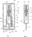
Fig. 1 is the side cross-sectional view of first embodiment of the invention assembly 1;
Fig. 2 is the side cross-sectional view that is similar to Fig. 1, and the part illustrates first shell 2;
Fig. 3 is the plane graph of second shell 3;
Fig. 4 is the cross-sectional view along the X-X line intercepting of second shell 3 shown in Figure 3;
Fig. 5 is the plane graph of test pieces support 36 (not having paper) in second shell 3;
Fig. 6 is the side cross-sectional view of first embodiment of the invention assembly 1, illustrates how to use this assembly;
Fig. 7 is the side cross-sectional view of second embodiment of the invention assembly 101;
Fig. 8 is the side cross-sectional view that is similar to Fig. 1, and first shell 102 is shown;
Fig. 9 is the front view of second shell 103;
Figure 10 is the top view of second shell 103;
Figure 11 is the front view of test pieces lattice framing 36 (not having paper) in second shell 103;
Figure 12 is the cross-sectional view along the Y-Y line intercepting of second shell 103 shown in Figure 10;
Figure 13 is a cross-sectional view, and another embodiment that is equivalent to Fig. 4 blow vent structure is shown;
Figure 14 is a plane graph, and the body fluid guiding piece of the embodiment of the invention is shown;
Figure 15 is a perspective view, and the body fluid guiding piece of Figure 14 embodiment is shown;
Figure 16 is the plane graph of another embodiment body fluid guiding piece;
Figure 17 is again the plane graph of an embodiment body fluid guiding piece;
Figure 18 is the cross-sectional view of another embodiment body fluid guiding piece;
Figure 19 is a plane graph, and an embodiment is shown, among this embodiment, and three sides (being downside and left and right side) of body fluid guiding piece 34 covering fluid bodies inlets 33a wherein.
Figure 20 is the cross-sectional view along the Z-Z direction intercepting of Figure 19;
Figure 21 is a sketch map, is used to illustrate the operation of assembly 1 of the present invention;
Figure 22 is a sketch map, is used to illustrate the operation of assembly 1 of the present invention;
Figure 23 is a sketch map, is used to illustrate the operation of assembly 1 of the present invention.
The specific embodiment
The invention provides a kind of assembly that removably is fixed on the body fluid monitoring system, this assembly is equipped with the device of lancet and means and acquisition testing body fluid.
This assembly comprises puncture part, biological fluid extracting test section and first closure member.
The puncture part comprises the lancet and means and first shell.This lancet and means has at the puncture needle of its far-end with at the adapter that is connected in sting device in the body fluid monitoring system of its near-end.First shell has sleeve pipe, and lancet and means is installed in this sleeve pipe movably.This sleeve pipe has first opening and the proximal openings of far-end, and the former makes puncture needle can reach telescopic outside, and the latter can make adapter be connected on the sting device in the body fluid monitoring system.Lancet and means is fixed in the sleeve pipe before puncture, and the fixed position is near its proximal openings, and this sleeve pipe of gas-tight seal.The biological fluid extracting test section comprises the body fluid checkout gear and second shell, and this second shell has second opening of body fluid being introduced above-mentioned detection device.The first sealing member sealing member seals first opening.
In assembly of the present invention, first shell and second shell firmly fix each other, make first opening of the shell of winning and second opening of second shell form distal openings, make puncture needle can extend through this opening, constitute black box thus with puncture part and biological fluid extracting test section.
As mentioned above, in assembly of the present invention, puncture unit in first shell and the biological fluid extracting detecting unit in second shell are combined into the integral unit of shared its opening.The unitary puncture needle of this puncture can carry out disinfection in first shell of first opening and proximal openings sealing.
Therefore, the present invention also provide a kind of disinfectant puncture unit that can fit together with the biological fluid extracting detecting unit and can with the disinfectant biological fluid extracting detecting unit that the unit fits together that punctures.
Describe first preferred embodiment of the present invention in detail below with reference to accompanying drawing (main reference Fig. 1~6).Should be noted that identical in the accompanying drawings numbering represents equivalent unit, saved the explanation of this equivalent unit in the explanation.
Fig. 1 is the side cross-sectional view of first embodiment of the invention assembly 1.
Assembly 1 comprises first shell 2 of the lancet and means 4 of packing into and the shell 3 of the body fluid collecting and detecting device of packing into.
Fig. 2 be Fig. 1 puncture the part cross-sectional view.First shell 2 has the sleeve pipe 21 of wherein movable installation lancet and means 4.This sleeve pipe 21 has at first opening 22 of its far-end with in the proximal openings 23 of its near-end.
Fig. 3 is the plane graph of biological fluid extracting test section, and this part comprises the checkout gear 32 and second opening 31, and the two is connected, and makes body fluid to be guided to checkout gear 32.
Fig. 4 is the cross-sectional view along the X-X line intercepting of shell 3 shown in Figure 3.
Fig. 6 is a view, and the assembly 1 that is contained on the body fluid monitoring system 9 is shown.
Second shell, 3 its shapes are unrestricted, as long as it has the checkout gear 32 that forms therein.Second shell and first shell, 2 shared its openings 31 form its distal openings 5.This second shell can be fixed on its inside with first shell 2.
In first embodiment, surveyed area 32 is with respect to the specific angle of axial formation of the parts of the sleeve pipe 21 of fixed housing 2.
The shape of sleeve pipe 21 is unrestricted, can be cylindrical duct and rectangle pipe.For ease of making, sleeve pipe 21 is preferably cylindrical duct.
Lancet and means 4 has at the puncture needle 41 of its far-end and the adapter 42 that is connected with sting device 91 in the body fluid monitoring system 9 at its near-end.The shape of adapter 42 is not limited to convex shown in the drawings, can uses the adapter 42 of Any shape, as long as it can match with the shape of sting device 91.In addition, adapter 42 not necessarily will stretch out proximal openings 23.
Lancet and means 4 is fixed on the position near sleeve pipe 21 close ends, promptly is fixed on the position that puncture needle 41 does not stretch out first opening 22.Lancet and means 4 is securely fixed in the sleeve pipe 21, its fastening degree makes puncture needle 41 can not extend through first opening 22 before use, make it possible to achieve the attended operation of adapter 42 and sting device 91, make the thrust that to utilize sting device 91 in use promote lancet and means 4, thereby make adapter 42 break away from the fixed position.The device of fastening lancet and means 4 is unrestricted.Fastening lancet and means 4 can be in order to following method: forming geared assembly on the inner surface of sleeve pipe 21 and/or on the outer surface of lancet and means 4; Utilize the frictional force between the outer surface of the inner surface of sleeve pipe 21 and lancet and means 4; Utilize bonding agent or burning-on method to make contact surface form weak combination.
The lancet and means fixture works also to prevent that lancet and means 4 from throwing off and the effect of sealing proximal openings 22.Illustrate as following, prevent that mechanism that lancet and means is thrown off from can guarantee after use processing components safely, can not take place because of puncture needle 41 accidental danger of stretching out the jacket exterior prick skin.Specifically be, when the main body of body fluid monitoring system 9 is taken off assembly 1, because adapter 42 is embedded in the groove 92 of sting device 91 far-ends securely,, it is fixed on the lancet and means fixture so lancet and means 4 can be pulled to the direction near its near-end.The sealing mechanism of proximal openings 22 can prevent that inside pipe casing is subjected to antibacterial and other infection by microorganisms.
In this case, lancet and means 4 is fixed on before use near on the position of proximal openings 23, makes proximal openings 23 by lancet and means 4 sealings.This encapsulating method of proximal openings 23 is identical with the method for fixing lancet and means 4, and in typical embodiment, lancet and means 4 is embedded in the space that is formed by spine 25, and this spine is along the circumferencial direction extension of the inner surface of sleeve pipe 21, as illustrated in fig. 1 and 2.Perhaps, the inside of sleeve pipe 21 is tapered near its close end, lancet and means 4 is embedded in this close end that attenuates of sleeve pipe 21 securely, lancet and means 4 is embedded between the protuberance that forms on sleeve pipe 21 certain part inner surface in the space so that sleeve pipe 21 near the inner surface of its near-end and lancet and means 4 near forming airtight contact between the outer surface of its near-end.
When body fluid monitoring system 9 is taken off assembly 1, lancet and means will return to the close end of first shell 2, because lancet and means 4 is connected on the sting device 91 of body fluid monitoring system 9 through adapter 42.When lancet and means 4 has embedded when being fixed in the spine 25 that said fixing/sealing device for example along the circumferential direction extends, adapter 42 will be thrown off with sting device 91, thereby assembly 1 last and body fluid monitoring system 9 disengagements.In the process of throwing off, just make puncture needle 41 be firmly fixed at sleeve pipe 21, thereby can prevent reliably that puncture needle 41 from reaching the outside of second opening 31.So just, can prevent puncture needle 41 prick skin by accident after use.
As mentioned above, being preferably in proximal openings 23 utilizes the gas-tight seal of lancet and means 4 to form the gas-tight seal of sleeve pipe 21.Perhaps utilize the second sealing member (not shown) sealing proximal openings 23 as first sealing member, will illustrate as following.In this case, can utilize or not utilize lancet and means 4 to seal proximal openings 23.
When using the proximal openings 23 of lancet and means 4 Sealed casing pipes 21, lancet and means 4 must embed sleeve pipe 21 in the position near its near-end, so lancet and means 4 its cross sections must be corresponding to the cross section of sleeve pipe 21.In principle, illustrate as following that lancet and means 4 material therefors are identical with first shell 2 or second shell 3, lancet and means 4 material therefors preferably have elasticity to a certain degree.
First shell, 2 used exemplary materials comprise the thermoplastic resin of ABS plastic, polyethylene, polypropylene, polystyrene, polyvinylidene chloride resin, polyethylene glycol oxide, thermoplastic polyurethane, polymethylene methacrylate (polymethylene methacrylate), polyoxyethylene, fluororesin, poly-phthalic acid ethylidene ester and other available injection-molded molding; And phenolic resins, epoxy resin, silicone resin, unsaturated polyester (UP) are to fat and other thermosetting resin.
Because sealing first opening 22 and proximal openings 23 are so the inside of sleeve pipe 22 remains on the gas-tight seal state.First opening 22 is by 6 sealings of first sealing member.As shown in drawings, first sealing member 6 is membranaceous, with bonding agent or be fixed on the periphery of first opening 22 by burning-on method.
Though for ease of carrying out bonding with bonding method or burning-on method and peeling off subsequently, first sealing member 6 is preferably diaphragm, first sealing member 6 also can be lid or connector shape, as shown in Figure 8.
At sealing lancet and means 4 sleeve pipe 21 of sterilizing in the inside of sleeve pipe 21 and after sealing proximal openings 23, the inside of first shell 2 is remained under the disinfection; Perhaps disinfectant lancet and means 4 is enclosed in the inside of disinfectant sleeve pipe 21, makes the inside of sleeve pipe 21 keep sealing, up to use.For ease of operation, the sleeve pipe 21 of sterilizing again after sealing lancet and means 4 and sealing proximal openings 23 is best in these methods.
Can carry out disinfection with any method, for example carry out disinfection with methods such as EOG, gamma-rays, electron raies.
As mentioned above, can remain in the sterilization of guaranteeing sleeve pipe 21 inside under the state of use always first shell 2 and second shell 3 are fitted together, form assembly 1.
Following main reference Fig. 3~5 explanation biological fluid extracting test sections.
Body fluid checkout gear 32 is equipped with in this biological fluid extracting test section portion within it, and this part comprises second shell 3, and this shell has second opening 31 that is used for body fluid is introduced checkout gear 32.
In the present embodiment, second opening 31 is formed on the basal surface 3a of second shell 3, is in eccentric position.Wall at the shell 3 of second opening, 31 sidepieces has shoulder 3b, so that fix a part of first shell 2 at least.Test pieces shell 32a is configured on the basal surface 3a of shell 3, is positioned at a side that is different from second opening, 31 places.
In Fig. 3 and Fig. 4, application testing sheet in body fluid checkout gear 32.This test pieces (body fluid checkout gear) 32 is fixed on the test pieces support 36, and this support forms the groove on the test pieces shell 32a.Body fluid inlet 33a and fluid flowing path 33 are used for body fluid is directed to test pieces 32 from body fluid inlet 33a, this body fluid inlet 33a and be used for body fluid is formed between the wall of the test pieces shell 32a and second shell 3 from the fluid flowing path 33 that body fluid inlet 33a guides to test pieces 32.Should be noted that the body fluid checkout gear is not limited to test pieces, can adopt any device of the body fluid checkout gear that is fit to do body fluid monitoring system 9.
Second shell, 3 material therefors can be identical with the material of first shell 2.When the body fluid measuring device 93 of body fluid monitoring system 9 was the Optical devices of measuring according to the chromogenic reaction of test pieces, shell 3 preferably included opaque material, prevents the influence of exterior light thus, increases accuracy of measurement.For ease of determining body fluid flowing in fluid flowing path 33, second shell 3 can comprise the semi-transparent resin of being with color.
The cross section of fluid flowing path 33 and length can change according to measuring the desired body liquid measure.Yet fluid flowing path 33 preferred design become can reduce to stay the body fluid volume in the fluid course 33 as far as possible.Fluid flowing path 33 generally includes a groove, and its cross section is semicircle, V-arrangement or rectangle, and for reducing to remain on the body fluid volume in the fluid flowing path 33, it is rectangular shallow trench that fluid flowing path 33 preferably includes cross section.The degree of depth of groove is preferably in the scope of about 0.05~0.5mm, and its width is preferably in the scope of about 0.5~3mm.Fluid flowing path 33 preferably has short length, but this length depends on the position of the body fluid measuring device 93 of fluid inspection system 9.Yet the length that is fit to is in the scope of about 5~15mm.
When body fluid longshore current body stream 33 when body fluid inlet 33a flows to test pieces 32 closed system, capillarity may just fail before body fluid reaches test pieces 32.For this situation, need the configuration blow vent, promptly on test pieces support 36, form blow vent.
The preferred structure of blow vent is shown on the plane graph of test pieces support 36 of Fig. 5.In this structure, terminal 33b at the fluid course 33 of test pieces 32 1 sides forms test pieces supporting member 38 and blow vent 37, feasible fixing test sheet as illustrated in fig. 4, wherein, between the periphery of the periphery of test pieces 32 and test pieces support 36, form gap 39a, and between the lower surface 32 of test pieces 32 and test pieces support 36, form gap 39b.This test pieces 32 is supported between the terminal 33b of fluid flowing path 33 of test pieces supporting member 38 and test pieces 32 1 sides.Preferably be about 0.01~0.3mm at the lower surface of test pieces 32 and the gap 39b between the test pieces support 36.
The blow vent structure is not limited to said structure, and test pieces 32 can be configured in about centre of fluid flowing path 33 1 sides, makes blow vent 39a be formed on the end of fluid flowing path 33, as shown in figure 13.
Its manufactured materials of test pieces shell 32a that forms fluid flowing path 33 is identical with second shell 3.Yet test pieces shell 32a the most handy highly-hydrophilic material for example acrylic resin (aeryl resin) make.As test pieces shell 32a during with the not strong material of hydrophilic, the surface that can handle second shell 3 makes this surface possess hydrophilic property, thereby improves the suction effect that body fluid sucks fluid flowing path 33.Common this processing comprises that physics activates and handles that for example ozonization, Cement Composite Treated by Plasma, glow discharge processing, Corona discharge Treatment, irradiation under ultraviolet ray are handled; And be coated with surfactant, water solublity silicone, hydroxy propyl cellulose, Polyethylene Glycol, polypropylene glycol etc.
Can in all sorts of ways and form fluid flowing path 33.When forming fluid flowing path 33, can when the injection-molded test pieces shell 32a and second shell 3, form fluid flowing path 33 with the test pieces shell 32a and second shell 3.Perhaps can and on second shell 3, form fluid flowing path 33, perhaps a soleno-channel parts can be fixedly secured in shell 3 and form this stream by fluting or punching press shell 3.
Fluid detecting device or test pieces 32 are not limited to the device of any specific pattern, and can adopt any device that can be complementary with the body fluid measuring device 93 of body fluid monitoring system 9.For example, when body fluid measuring device 93 is optical measuring devices 93, and when being used to detect chromogenic reaction on the test pieces under the situation of glucose in measuring blood, this test pieces can use glucoseoxidase, peroxidase and developer to soak into, then drying.This test pieces 32 is perforated membrane preferably, and it constitutes supatex fabric, Woven fabric, drawing of fiber sheet etc., and making material for example is polyester, polyamide, polyolefin, polysulfones, cellulose etc.Because the various different reagent of test pieces 32 usefulness and body fluid dipping, thus test pieces preferably make of water wetted material, or treated and form hydrophilic.Test pieces 32 can be single-layer sheet or multilayer tablet.
Provide this guiding piece 34 can fully body fluid be introduced fluid flowing path 33.Therefore the present invention also provides a kind of biological fluid extracting detecting unit, and this unit comprises: body fluid inlet 33a; Can measure the test pieces 32 of composition to be measured in the body fluid; Body fluid is drawn into the stream 33 of test pieces from body fluid inlet 33a; And be configured in body fluid guiding piece 34 on the body fluid inlet 33a periphery.A kind of biological fluid extracting detecting unit also is provided in the present invention, and wherein above-mentioned parts are contained in the shell 3.
The making material of body fluid guiding piece 34 is identical with the material of second shell or test pieces shell 32a, and these fluid guiding piece 34 like fluid flowing paths 33 equally make possess hydrophilic property.
Body fluid guiding piece 34 is configured in second opening 31 of second shell 3.
When body fluid guide body 34 its shapes are improper, there is not the excess body fluid of sucking-off body fluid inlet 33a will be diffused into around second opening 31, cause hygienic issues.The inappropriate body fluid guiding piece 34 of shape will cause and can not fully body fluid be sucked fluid flowing path 33, increase and measure required body fluid volume, increase patient's burden thus.Therefore body fluid guiding piece 34 its structures should be guided to body fluid body fluid inlet 33a apace, and can keep a large amount of body fluid, in case diffusion of body fluids or flow to the peripheral region.The typical structure of body fluid guiding piece 34 is two or more protuberances that are formed on body fluid inlet 33a periphery.
The plane graph of Figure 14 and the perspective view of Figure 15 illustrate an embodiment of body fluid guiding piece.Body fluid guiding piece as embodiment comprises that shape is the guide member 34a and the 34b of track, and these guide members are formed on the edge of opposite end of body fluid inlet 33a.
The spatial volume that is formed by body fluid guiding piece 34 can change according to the body fluid diameter that the body fluid volume of gathering is promptly gathered.The width of guiding piece 34 equal at the most the to gather diameter of body fluid.For example, as under the situation of monitoring blood glucose when gathering about 4 μ L body fluid, appear at the about 3mm of its diameter of body fluid on the skin surface, in this case, guide body 34 its width preferably are about 1~3mm, highly be about 0.5~3mm, and length are about 1~3mm.The height of guide member 34a and 34b preferably equals the maximum gauge of body fluid inlet 33a.
The shape of guide member 34a and 34b is not limited to shape shown in Figure 14, and interior surface opposing is parallel to each other among Figure 14.Guide member 34a and 34b also can be designed to shape as shown in figure 16, and wherein the space that is formed by opposite inner face broadens gradually in the direction near second opening, 31 centers of circle.In other words, the body fluid guiding piece is designed such that the width between above-mentioned side member increases to its distal side gradually from above-mentioned entrance side.
In addition, guide member 34a and 34b can be configured to as shown in figure 17, and the diameter that two opposite inner face that make guide member 34a and 34b form in the junction of body fluid inlet 33a is less than the diameter of body fluid inlet 33a.When guide member 34a and 34b are designed to space that two apparent surfaces form when the center that body fluid drips becomes big gradually, body fluid just can be sent into fluid flowing path 33 from skin surface smoothly, because the body fluid surface tension force in body fluid guiding piece 34 is less than the surface tension in the fluid flowing path 33, thereby all body fluid will be sent to body fluid inlet 33a in guiding piece 34, the incoming fluid stream 33 then, so just do not need to consider the dead volume in the guiding piece 34.
Body fluid guiding piece 34 is not limited to the aforesaid embodiment that comprises two guide member 34a and 34b, can comprise three or four guide members, wherein body fluid guiding piece 34 covers all four sides (left side, right side and upper and lower side) of body fluid inlet 33a or covers three sides (left side, right side and downside).Body fluid guiding piece 34 also comprises the continuous guiding piece that extends along circumferential direction, semi-circular, arched member etc.
The basal surface of the basal surface of body fluid guiding piece 34 and second shell 3 not necessarily forms same plane.Figure 18 is the cross-sectional view corresponding to embodiment embodiment illustrated in fig. 4.In this embodiment, the basal surface of body fluid guiding piece 34 is not on the basal surface of second shell 3.
In this preferred embodiment, the basal surface of body fluid guiding piece 34 is higher than the basal surface of second shell 3 (second opening 31), thus when placing monitoring system 9 on the skin the just top surface of contact projection skin of basal surface of body fluid guiding piece 34.In another embodiment, the basal surface of body fluid guiding piece 34 beyond the basal surface of second shell 3, the top surface of contact projection skin not, and contact drop only.The suitable height of body fluid guiding piece 34 basal surfaces distance second shell 3 basal surfaces preferably is about 0.5~1.5mm in the scope of 0.1~5mm.
Figure 19 is a plane graph, and an embodiment of body fluid guiding piece 34 is shown, and this guiding piece comprises two guide member 34a and 34b and the lower side panel parts 34c that covers body fluid inlet 33a three sides (right side, left side and downside).Figure 20 is the cross-sectional view along the Z-Z line intercepting of Figure 19.In this preferred embodiment, comprising as shown in the figure that the structure of lower side panel parts 34c can prevent air admission body fluid, also is like this even there is when adding aspirator in body fluid monitoring system 9 slightly air to flow through under the situation in the basal surface of opening 31 and the gap between the skin surface.Side direction guide member 34a and 34b are mounted to the basal surface of above-mentioned second shell 3 and form angle less than 90 °.In addition, this structure is included on the guiding piece 34 distal portion downsides, the protuberance 34d on the concrete infra side plate parts 34c downside, and this structure can be with volume restrictions volume in the clearance space on introduce by capillarity of body fluid.
When with above-mentioned system acquisition body fluid, puncture needle 41 moves ahead through near the head of body fluid guiding piece 34 or run in the guide between the above-mentioned body fluid guide member at acupuncture skin.When puncture needle 41 prick skin and when forming the body fluid drop of required amount, this body fluid drips and just touches body fluid guiding piece 34.Body fluid is introduced into fluid flowing path 33 subsequently, enters test pieces 32 again.The distance of passing through between path and body fluid guiding piece 4 head ends of puncture needle 41 is considered the body fluid volume that measurement is required, and about at the most 3mm is relatively good, preferably about 1mm.When body fluid guiding piece 34 be as shown in the figure comprise this guiding piece of guide member 34a and 34b the time, puncture needle can be walked between guide member 34a and 34b.
Should be noted that when the basal surface 3a of second shell 3 tilt angle alpha the relative body fluid guiding piece 34 of the test pieces shell 32a same angle [alpha] that also tilts.
The method that first shell 2 is firmly secured to second shell 3 is not particularly limited.In one embodiment, first shell 2 is fixed on second shell 3, the sleeve pipe 21 of the shell 2 of winning is leaned against on the shoulder 3b of second shell 3, and make the geared assembly 24a of first shell 2 and geared assembly 35a and the 35b that 24b meshes second shell 3.Perhaps, by bonding agent or utilize burning-on method that contact surface is bonded together, fix first shell 2 and second shell 3 thus.This structure can make the end user soon first shell 2 and second shell 3 be dressed up assembly 1, does not need the end user dividually first shell 2 and second shell 3 to be contained in (see figure 6) in the fluid inspection system 9.This means that again the end user can be used as assembly 1 and unloads first shell 2 and second shell 3 soon.
Perhaps, 2 pressurizations of first shell can be embedded in second shell 3, as shown in Figure 7.
Should be noted that in the above-described embodiments test pieces shell 32a is formed on the basal surface 3a.When second shell 3 has its inside can fixedly secure the sleeve pipe of first shell 2 time, can reduce second shell 3 and take up space.As second embodiment this embodiment is described below.
Assembly 1 preferably is sealed in the guard shield 8 after assembling, promptly form distal openings 5 in assembling, make the sleeve pipe 21 of first shell 2 seal and disinfectant puncture needle 41 is sealed in this sleeve pipe, and on second shell, form after the fluid detecting device, be sealed in guard shield 8 again.The structure of this guard shield 8 is unrestricted, as long as the assembly 1 of specific embodiment can be sealed in its inside.The embodiment that is shown in the guard shield 8 of accompanying drawing is made of diaphragm, and the guard shield 8 of this embodiment is torn module from otch 81 before use and just can be removed soon.First sealing member 6 has adapter 61, and this adapter 61 is connected in the part inwall of guard shield 8, in this case, can remove first sealing member 6 from first opening 22 simultaneously when removing guard shield 8.Equally, when the second sealing member (not shown), this second sealing member also is connected in the inwall of guard shield 8, in this case, can also remove first sealing member 6 and second sealing member from first opening 22 and proximal openings 23 respectively when removing guard shield 8.
In the above-described embodiments, guard shield 8 is made of diaphragm.Guard shield 8 also can comprise the rigidity plastics box.Guard shield 8 material therefors are unrestricted; When guard shield 8 comprised diaphragm, the material of making backplate 8 was identical with the material of first sealing member 6 and second sealing member, and when guard shield 8 comprised the duroplasts box, it is identical with the material of first shell 2 or second shell 3 that it makes material.
The invention provides a kind of body fluid monitoring system, this system comprises body fluid monitoring system main body and said modules.In this body fluid monitoring system, main body comprises the sting device that can make lancet and means protract and retreat, measures the device of composition to be measured in the body fluid and the removably fixing device of assembled components shell.This assembly is fixed in the main body by fixture, and the adapter of lancet and means embeds in the groove of sting device far-end.
Operation below with reference to Fig. 6 and Figure 21~23 illustrated components 1.
Be sealed at assembly 1 under the situation of guard shield 8, when when assembly 1 is removed guard shield 8, can in company with guard shield 8 together remove first sealing member 6 (and second sealing member, if any).Then assembly 1 is connected on the far-end of body fluid monitoring system 9.The adapter 42 of lancet and means 4 is embedded in the groove that forms on sting device 91 distal portion, and compression is connected in the spring 94 of sting device 91 thus.Should be noted that and dispose for example O shape ring of parts on the distal portion that is preferably in body fluid detection system 9, so that assembly 1 is fixed in the distal portion of body fluid monitoring system 9 reliably airtightly.This moment, this system just can be used for measuring at any time.
When measuring, the body fluid monitoring system is pressed on the skin, and makes the distal openings 5 of assembly 1 be positioned at site of puncture (seeing Figure 21).Utilize operating knob 96 to unclamp the spring 94 of compression then, push sting device 91 to its far-end.Sting device 91 promotes lancet and means 4 subsequently, makes puncture needle 41 thrust skin (seeing Figure 22).After the puncture, make spring 94 return to its original length or utilize different spring (not shown) to be withdrawn into puncture needle 41 in the assembly and be fixed therein.Body fluid detection system 9 at this moment is shown in Fig. 6.
Body fluid detection system 9 also has aspirator.This aspirator is not limited to any particular type, as long as it can reduce the main body cover pressure inside when being pressed in opening 5 on the site of puncture.Typical aspirator is electric pump and manual pump.
Body fluid is just from body fluid guiding piece 34 incoming fluid streams 33 when flow out from the acupuncture position puncture back body fluid (blood), and then flows to test pieces 32 (seeing Figure 23).Reach the body fluid of test pieces 32 and the reagent reacting that is fixed in the above, promptly carry out chromogenic reaction.Use the optical element (light emitting devices 93a or optical pickup apparatus 93b) in the body fluid measuring device 93 to absorb (or emission) measurement then, measure the color that test pieces 32 shows, and calculate the amount of component to be measured.After finishing sequence of operations, take off assembly 1 from the far-end of body fluid monitoring system 9.Being contained in assembly 1 inner lancet and means 4 also takes off from system 9 simultaneously.
The body fluid measuring device that should be noted that body fluid monitoring system 9 is not limited to above-mentioned Optical devices, and assembly 1 should have the sort of body fluid checkout gear 32 of coupling the type body fluid measuring device 93.In other words, body fluid checkout gear 32 is not limited to test pieces.Typical case's cooperation of body fluid checkout gear 32 and body fluid measuring device 93 is electrodes and will measures the processor that current conversion changes blood glucose value into.
In said modules of the present invention, second shell can be a kind of like this shell, and its split shed is formed on its main part; Inside at this shell forms sleeve pipe, the feasible sleeve pipe that can embed a part of first shell at least; The surveyed area of body fluid checkout gear is configured on the outer surface of second tubular quill housing.When adopting this structure, can reduce the shared space of body fluid checkout gear, and can reduce the size of assembly as far as possible.
Below with reference to Fig. 7~12 explanation second embodiment of the present invention, this embodiment has second shell of this structure.
Fig. 7 is the cross-sectional view of second embodiment of the invention assembly 101.
Shown in the top view of the front view of Fig. 9 and Figure 10, second shell 103 has second opening 131, and checkout gear (test pieces) 132 is configured on second shell 103.
As mentioned above, first shell 102 has the sleeve pipe 121 of portion within it, and lancet and means 104 is contained in this sleeve pipe 121 movably.The shape of this conduit 121 is unrestricted, and it can cylindrical duct or rectangle pipe.For ease of making member, sleeve pipe 121 is cylindrical tube preferably.
Lancet and means 104 has the puncture needle 141 of far-end and the adapter 142 of near-end, and this adapter is connected in the sting device (not shown, but be equivalent to the sting device 91 of first embodiment) of body fluid monitoring system.The shape of adapter 142 is not limited to protrusion type shown in the drawings, can use the adapter of Any shape, if it can with the form fit of sting device.In addition, adapter 142 not necessarily stretches out proximal openings 123.
Lancet and means 104 is fixed on the position near sleeve pipe 121 near-ends, promptly is positioned at the position that puncture needle 41 does not stretch out first opening 122.Lancet and means 104 is firmly secured to sleeve pipe 121, make puncture needle 141 not stretch out first opening 122 before use, make it possible to achieve the attended operation of adapter 142 and sting device, and make the driving force that utilizes sting device in use can make adapter 142 break away from its fixed position when promoting lancet and means 104.Fixedly the method for lancet and means 104 is unrestricted, and lancet and means 104 can adopt following method to fix: forming geared assembly on the inner surface of sleeve pipe 121 and/or on the outer surface of lancet and means 104; Utilize the frictional force between sleeve pipe 121 inner surfacies and lancet and means 104 outer surfaces; Or it is weak bonding with bonding method or burning-on method contact surface to be formed.
Illustrate that as following when proximal openings 123 be can't help the sealing of second sealing member, lancet and means 104 was fixed on the position near proximal openings 123 before using, make second opening 123 by lancet and means 104 sealings.The method of this sealing proximal port 123 can be the fixing used method of lancet and means 104, in exemplary embodiments, lancet and means 104 embeds in the space that is formed by spine 125, and this spine extends along circumferential direction, be formed on the inner surface of sleeve pipe 121, as shown in Figure 7.Perhaps, the inside of sleeve pipe 121 is tapered near close end, lancet and means 104 is embedded in the close end that attenuates of sleeve pipe 121, lancet and means 104 is embedded in the space between the protuberance that forms on certain part on sleeve pipe 121 inner surfacies, be beneficial to telescopic near its close end outer surface and lancet and means 104 near forming airtight contact between the outer surface of its close end.
When assembly 101 is separated with the fluid inspection system, the lancet and means 104 that is connected in body fluid monitoring system sting device by adapter 142 will be pulled back to the close end of first shell 102.When lancet and means 104 embedded said fixing/sealing device securely for example along spine 125 that circumferential direction extends, adapter 142 just separated with sting device, thereby in the end, assembly 101 is thrown off with the body fluid monitoring system.In the process that unloads, puncture needle 41 becomes and is fastened in the sleeve pipe 121, thereby can prevent reliably that puncture needle 141 from stretching out second opening 131.Stab skin by accident so after use, can prevent puncture needle 141.
Because lancet and means 104 must embed the position of the close close end of sleeve pipe 121, so lancet and means 104 its cross sections should be corresponding to the cross section of sleeve pipe 121.In principle, the constituent material of lancet and means 104 illustrates as following, and is identical with first shell 102 or second shell, 103 material therefors, and lancet and means 104 material therefors preferably have certain elasticity.
Lancet and means 104 being enclosed in sleeve pipe 121 inside and sealing proximal openings 123 back disinfection conduit 121, make the inside of first shell 102 remain on disinfection thus.Perhaps will be disinfectant lancet and means 104 be sealed in disinfectant sleeve pipe 121 inside, and make the inside of sleeve pipe 121 remain on closed state to use up to it, so also can make the inside of first shell remain on disinfection.In these methods, for ease of operation, the sterilization of carrying out sleeve pipe 121 after sealing lancet and means 104 and sealing proximal openings 123 again is best.Can carry out disinfection with any method, for example carry out disinfection with EOG method, gamma-rays method, electron ray method etc.As mentioned above, when the disinfection of guaranteeing sleeve pipe 121 inside can remain to the operating period, first shell 102 and second shell 103 are assembled formation assembly 101.
The material that is used to make first shell 102 comprises the thermoplastic resin that ABS plastic, polyethylene, polypropylene, polystyrene, polrvinyl chloride, polyvinylidene chloride resin, polyethylene glycol oxide, thermoplastic polyurethane, polymethylene acrylate, polyoxyethylene, fluororesin, Merlon, polyamide, acetal resin, acrylic resin, poly-phthalic acid ethylidene ester and other can injection-molded; And phenolic resins, epoxy resin, silicone resin, unsaturated polyester resin and other thermosetting resin.
Can make sleeve pipe 121 remain on the gas-tight seal state after sealing first opening 122 and proximal openings 123.First opening 122 is by sealing member 106 sealings.As shown in the figure, the first sealing member shape is a connector, and it embeds and is fixed in first opening 122, thus the inside of gas-tight seal sleeve pipe 121.Should be noted that first sealing member 106 also can be for carrying out bonding and lid that be easy to peel off or stopper with bonding method or burning-on method easily.Though preferably adopt the fixedly method gas-tight seal proximal openings 123 of lancet and means 104 of above-mentioned embedding, also can seal proximal openings 123 with the second sealing member (not shown) that is similar to first sealing member 106.
The used material of second shell 103 is identical with the material of first shell 102.When the body fluid measuring device in the body fluid monitoring system was the Optical devices that can measure the chromogenic reaction on the test pieces, shell 103 preferably included opaque material, can prevent the influence of exterior light thus, increased accuracy of measurement.For ease of confirming body fluid flowing in fluid flowing path 133, second shell 103 can comprise the semi-transparent resin of being with color.
In this embodiment, body fluid inlet 133a and the fluid flowing path 133 that utilizes capillarity that body fluid is guided to test pieces 132 from body fluid inlet 133a are formed on the periphery of second opening 131.Figure 12 is the amplification cross-sectional view along second shell 103 of the Y-Y line of Figure 10 intercepting of second embodiment.As shown in figure 12, fluid flowing path 133 is made of fluid flowing path part 133e, 133d and 133c, and these parts intersect each other at a certain angle.Specifically be, fluid flowing path part 133c stretches out from body fluid inlet 133a, and the axis of fluid flowing path part 133d from fluid flowing path part 133c along second shell 103 protrudes upward, and fluid flowing path part 133e stretches to test pieces 132 from fluid flowing path part 133d.In this embodiment, this fluid flowing path forms the gap when being contained in test pieces shell 132a on second shell 103.
The cross section of fluid flowing path 133 and length can change according to measuring required body fluid volume.Yet becoming to make, the fluid flowing path preferred design stays the body fluid volume that reduces in the fluid flowing path 133 as far as possible.Fluid flowing path 133 generally include have semicircle, the groove of V-arrangement or rectangular cross section, for reducing to stay the body fluid volume of fluid flowing path 133, fluid flowing path 133 preferably includes the shallow trench with rectangular cross section.Its degree of depth preferably is about 0.05~0.5mm, and width preferably is about 0.5~3mm.Though it is the length of fluid flowing path depends on the position of the fluid measurement instrument of fluid inspection system, preferably shorter.Its suitable length is in the scope of about 5~15mm.
When body fluid longshore current body stream 133 when body fluid inlet 133a flows to test pieces 132 closed system, capillarity may just stop before body fluid arrives test pieces 132.For this situation, must dispose blow vent, specifically, form the structure shown in a kind of Figure 11 plane graph, in this structure, on the outer surface of shell 103, form test pieces support 136, this support forms recess.In this structure, in test pieces 132 1 sides, form test pieces supporting member 138 and blow vent 137 at the end of fluid flowing path 133 133b, make test pieces 132 to fix by shown in Figure 12, wherein between the edge of the outward flange of test pieces 132 and test pieces support 136, form gap 139a, and between the lower surface of test pieces 132 and test pieces support 136, form gap 139b.Test pieces 132 is supported between the end 133b of test pieces supporting member 138 and fluid flowing path 133.
As shown in figure 12, in the fluid flowing path 133 of second embodiment of the invention, fluid flowing path part 133c stretches out from body fluid inlet 133a, and with crossing along second shell, 103 axially extended fluid flowing path part 133d, form certain angle, and fluid flowing path part 133d intersects with the fluid flowing path 133c that stretches to test pieces 132, forms certain angle.When full-bodied body fluid fluid is mobile along the fluid flowing path of this shape, because surface tension forms crescent at the front end of liquid stream probably.For this situation, in the fluid flowing path of present embodiment, each angle part that is preferably in fluid flowing path 133 forms the protuberance that stretches into fluid flowing path 133, makes that forming half moon-shaped fluid can contact this protuberance at fluid during by fluid flowing path.Specifically, on the bight that forms between fluid flowing path part 133c and the 133d, form the protuberance 135a that stretches into fluid flowing path part 133c, and on test pieces 132, form the protuberance 135b that stretches into fluid flowing path part 133b.Protuberance 135a and 135b will discharge the surface tension of decision crescent configuration.
Should be noted that the crescent configuration is a kind of phenomenon that occurs in the pipe, under surface tension effects, make when fluid stops to move forward in the pipe that this phenomenon shows obviously especially, and on liquid level the recessed or protruding surface of shape.The crescent that forms during by liquid-soaked when pipe is recessed crescent, and liquid surface will raise along inner surface.Crescent configuration most probable appears near angle capillaceous or this bight.
Form fluid flowing path 133 with the material of making second shell 103.For example acrylic resin (acryl resin) making of material that fluid flowing path 133 the most handy hydrophilic are strong.When the hydrophilic of material was insufficient, the surface that can handle fluid flowing path 133 made it become water-wetted surface, thereby improved the swabbing action of 133 pairs of body fluid of fluid flowing path.The typical processing comprises that physics activates processing, and for example ozonization, plasma treatment, glow discharge processing, Corona discharge Treatment, ultra-vioket radiation are handled; And be coated with surfactant, water solublity silicone, hydroxypropyl fiber, Polyethylene Glycol, polypropylene glycol etc.
On the edge of body fluid inlet 133a, preferably has body fluid guiding piece 134.The effect of this body fluid guiding piece 134 is that the body fluid with contact guidance body 134 is directed to body fluid inlet 133a.This body fluid guiding piece 134 can be with the material that forms second shell 103 or fluid flowing path 133, and the situation of body fluid guiding piece 134 and fluid flowing path 133 is the same should to be processed into possess hydrophilic property.Its structure of body fluid guiding piece should be directed to body fluid body fluid inlet 133a soon, and can keep a large amount of body fluid, prevents this diffusion of body fluids and flows to the peripheral region.When the shape of body fluid guiding piece 134 is improper, not the excess body fluid that is siphoned away by body fluid inlet 133a will be diffused into second opening 131 around, cause antihygienic problem.The inappropriate body fluid guiding piece 134 of shape also causes and can not fully body fluid be drawn in the fluid flowing path 133, thereby has also increased and measure required body fluid volume, has increased patient's burden.Typical body fluid guiding piece 134 comprises guide member 134a and the 134b that forms track, and they are configured on two opposite edges (left and right side) of body fluid inlet 133a.Should be noted that the opposite inner face of guide member 134a and 134b or parallel to each other, or uneven, make the space that between two opposite inner face, forms broaden gradually to the center that body fluid drips.A kind of structure in back is better, because can be more reliably and aspirate body fluid more quickly.Body fluid guiding piece 134 can be a kind of like this guiding piece, promptly also comprises the guiding piece of the guide member that covers body fluid inlet 133a downside.The body fluid guiding piece 134 of other embodiment also is available, and the body fluid guide body can be such guiding piece, and all four sides (left and right, upper and lower four sides) at fluid intake 133a in this guiding piece all have guide member.
Body fluid guiding piece 134 is preferably formed as an inner space, about 1~the 3mm of its width, highly about 0.5~3mm, the about 1~3mm of length, because the about 3mm of its diameter of drop that the body fluid of about 4 μ L amount forms, guiding piece 134 is preferably formed as the space that is equivalent to maximum desired body liquid measure.The height of guide member 134a and 134b preferably is equivalent to the maximum gauge of body fluid inlet 133a.
When puncture, near the head of puncture needle 141 process liquid guiding piece 134 before skin puncture, or between above-mentioned body fluid guide member, walk.When puncture needle 141 prick skin and the body fluid that forms required amount dripped, this body fluid dripped and just contacts body fluid guiding piece 134.This body fluid is directed into fluid course 133 then, enters into test pieces 132 then.Path and the distance between body fluid guiding piece 134 heads at puncture needle 141 consider that the most about 3mm of measurement desired body liquid measure is better, preferably arrive about 1mm.
The surface of second shell 103 of close second opening 131 is preferably formed as and is curved surface 105a, and this curved surface is corresponding to the curved surface of site of puncture.This curved surface 105a plays a part distal openings 105 is directed to site of puncture (for example finger tip or protuberance).In the embodiment shown in fig. 9, second shell 103 has the curved surface 105a of its curved surface corresponding to finger tip, and the recessed region of this curved surface 105a helps distal openings is placed site of puncture on the finger tip.
Body fluid checkout gear or test pieces 132 are not limited to any particular type, can use any device that the body fluid measuring device with the body fluid monitoring system is complementary.For example, as under the situation of measuring blood when the body fluid measuring device is the optical measuring device that the chromogenic reaction on the test pieces is detected, test pieces 132 can be used glucoseoxidase, peroxidase and developer dipping, and then dry.Test pieces 132 is perforated membrane preferably, is made of supatex fabric, Woven fabric, drawing of fiber film etc., and it makes raw material is polyester, polyamide, polyolefin, polysulfones, cellulose etc.Because test pieces is soaked into all ingredients and body fluid, so possess hydrophilic property is made or be processed into to test pieces 132 the most handy water wetted materials.This test pieces 132 can be single-layer sheet or multilayer tablet.When test pieces 132 was multilayer tablet, as shown in drawings, these layers closely were stacked together each other.
The application mode of the assembly 101 of second embodiment assembly 1 with first embodiment of the invention basically is the same.
Industrial applicability
The invention provides a kind of and the assembly coupling of body fluid monitoring system, wherein lancet and means (is worn Pricker) be sterilized and kept this disinfection, until service time, and can keep away simultaneously Exempt from because the negative effect that the sterilization sting device causes is for example drawn by the reagent that immerses in the test pieces The adverse effect of sending out. Use assembly of the present invention and can guarantee to measure safely, because sterilization State can remain to the time of using lancet and means, and can guarantee to load onto reliably and unload Lower lancet and means and test pieces unit are because can operate simultaneously two unit.
Biological fluid extracting detecting unit of the present invention has the body fluid guiding piece, and this body fluid guiding piece can Effectively body fluid is directed to inside, unit, just can be complete by the body fluid of puncture and collection minimum Become to measure. Therefore no longer need extruding and massage site of puncture.
Claims (5)
1. biological fluid extracting detecting unit comprises:
The body fluid inlet;
Can measure the test pieces of composition to be measured in the body fluid;
Fluid flowing path utilizes capillarity that body fluid is directed to above-mentioned test pieces from above-mentioned inlet;
The body fluid guiding piece, along the outward flange formation of described inlet, described body fluid guiding piece comprises two or more guide members, described two or more guide members are the protuberances that form along above-mentioned inlet outward flange.
2. biological fluid extracting detecting unit as claimed in claim 1 is characterized in that, above-mentioned biological fluid extracting detecting unit is configured on the shell with opening, and above-mentioned body fluid guiding piece is positioned at above-mentioned opening.
3. biological fluid extracting detecting unit as claimed in claim 1 is characterized in that, the structure of above-mentioned body fluid guiding piece comprises the described guide member that is two side components and a lower side panel component form.
4. biological fluid extracting detecting unit as claimed in claim 3 is characterized in that, above-mentioned lower side panel parts have the protuberance that stretches out at its distal portions downwards.
5. as claim 3 or 4 described biological fluid extracting detecting units, it is characterized in that, above-mentioned body fluid guide member is designed so that the width between the above-mentioned side component increases to the distal side gradually from above-mentioned entrance side, and the surface tension of above-mentioned body fluid is less than the surface tension of above-mentioned fluid flowing path inside in the inner space that above-mentioned body fluid guide member is surrounded.
Applications Claiming Priority (15)
| Application Number | Priority Date | Filing Date | Title |
|---|---|---|---|
| JP215/99 | 1999-01-04 | ||
| JP00021599A JP3648081B2 (en) | 1999-01-04 | 1999-01-04 | Body fluid component measuring device |
| JP215/1999 | 1999-01-04 | ||
| JP63905/1999 | 1999-03-10 | ||
| JP63905/99 | 1999-03-10 | ||
| JP06390599A JP3659832B2 (en) | 1999-03-10 | 1999-03-10 | Body fluid component measuring device |
| JP193754/1999 | 1999-07-07 | ||
| JP193754/99 | 1999-07-07 | ||
| JP19375499 | 1999-07-07 | ||
| JP196829/99 | 1999-07-12 | ||
| JP19682999A JP3648098B2 (en) | 1999-07-12 | 1999-07-12 | Body fluid component measuring instrument |
| JP196829/1999 | 1999-07-12 | ||
| JP322465/1999 | 1999-11-12 | ||
| JP32246599A JP3898399B2 (en) | 1999-07-07 | 1999-11-12 | Assembly including lancet and body fluid component detection unit |
| JP322465/99 | 1999-11-12 |
Related Parent Applications (1)
| Application Number | Title | Priority Date | Filing Date |
|---|---|---|---|
| CNB998164232A Division CN1191786C (en) | 1999-01-04 | 1999-12-27 | Assembly having lancet and means for collecting and detecting body fluid |
Publications (2)
| Publication Number | Publication Date |
|---|---|
| CN1624448A CN1624448A (en) | 2005-06-08 |
| CN1315432C true CN1315432C (en) | 2007-05-16 |
Family
ID=27517929
Family Applications (2)
| Application Number | Title | Priority Date | Filing Date |
|---|---|---|---|
| CNB2004101019923A Expired - Fee Related CN1315432C (en) | 1999-01-04 | 1999-12-27 | Body fluid collecting and detecting device |
| CNB998164232A Expired - Fee Related CN1191786C (en) | 1999-01-04 | 1999-12-27 | Assembly having lancet and means for collecting and detecting body fluid |
Family Applications After (1)
| Application Number | Title | Priority Date | Filing Date |
|---|---|---|---|
| CNB998164232A Expired - Fee Related CN1191786C (en) | 1999-01-04 | 1999-12-27 | Assembly having lancet and means for collecting and detecting body fluid |
Country Status (7)
| Country | Link |
|---|---|
| US (1) | US6315738B1 (en) |
| EP (1) | EP1139873B1 (en) |
| KR (1) | KR100621944B1 (en) |
| CN (2) | CN1315432C (en) |
| AT (1) | ATE408372T1 (en) |
| DE (1) | DE69939598D1 (en) |
| WO (1) | WO2000040150A1 (en) |
Families Citing this family (216)
| Publication number | Priority date | Publication date | Assignee | Title |
|---|---|---|---|---|
| US7828749B2 (en) | 1996-05-17 | 2010-11-09 | Roche Diagnostics Operations, Inc. | Blood and interstitial fluid sampling device |
| US20020010406A1 (en) | 1996-05-17 | 2002-01-24 | Douglas Joel S. | Methods and apparatus for expressing body fluid from an incision |
| US7235056B2 (en) | 1996-05-17 | 2007-06-26 | Amira Medical | Body fluid sampling device and methods of use |
| EP1579814A3 (en) | 1996-05-17 | 2006-06-14 | Roche Diagnostics Operations, Inc. | Methods and apparatus for sampling and analyzing body fluid |
| US7666150B2 (en) | 1996-05-17 | 2010-02-23 | Roche Diagnostics Operations, Inc. | Blood and interstitial fluid sampling device |
| US6706000B2 (en) | 1997-11-21 | 2004-03-16 | Amira Medical | Methods and apparatus for expressing body fluid from an incision |
| US6036924A (en) | 1997-12-04 | 2000-03-14 | Hewlett-Packard Company | Cassette of lancet cartridges for sampling blood |
| US6391005B1 (en) | 1998-03-30 | 2002-05-21 | Agilent Technologies, Inc. | Apparatus and method for penetration with shaft having a sensor for sensing penetration depth |
| US6175752B1 (en) | 1998-04-30 | 2001-01-16 | Therasense, Inc. | Analyte monitoring device and methods of use |
| US8974386B2 (en) | 1998-04-30 | 2015-03-10 | Abbott Diabetes Care Inc. | Analyte monitoring device and methods of use |
| US8346337B2 (en) | 1998-04-30 | 2013-01-01 | Abbott Diabetes Care Inc. | Analyte monitoring device and methods of use |
| US8465425B2 (en) | 1998-04-30 | 2013-06-18 | Abbott Diabetes Care Inc. | Analyte monitoring device and methods of use |
| US8688188B2 (en) | 1998-04-30 | 2014-04-01 | Abbott Diabetes Care Inc. | Analyte monitoring device and methods of use |
| US8480580B2 (en) | 1998-04-30 | 2013-07-09 | Abbott Diabetes Care Inc. | Analyte monitoring device and methods of use |
| US9066695B2 (en) | 1998-04-30 | 2015-06-30 | Abbott Diabetes Care Inc. | Analyte monitoring device and methods of use |
| US6949816B2 (en) | 2003-04-21 | 2005-09-27 | Motorola, Inc. | Semiconductor component having first surface area for electrically coupling to a semiconductor chip and second surface area for electrically coupling to a substrate, and method of manufacturing same |
| JP4210782B2 (en) | 1999-10-13 | 2009-01-21 | アークレイ株式会社 | Blood sampling position indicator |
| DE10010694A1 (en) | 2000-03-04 | 2001-09-06 | Roche Diagnostics Gmbh | Lancet including tipped needle with body surrounding tip |
| US7780610B2 (en) | 2000-05-01 | 2010-08-24 | Terumo Kabushiki Kaisha | Component measuring instrument and chip |
| US6652814B1 (en) * | 2000-08-11 | 2003-11-25 | Lifescan, Inc. | Strip holder for use in a test strip meter |
| WO2002032332A1 (en) * | 2000-10-18 | 2002-04-25 | Mattoli Engineering Ltd. | Method and apparatus for plasma skin resurfacing |
| DE10053974A1 (en) | 2000-10-31 | 2002-05-29 | Roche Diagnostics Gmbh | Blood collection system |
| DE10057832C1 (en) * | 2000-11-21 | 2002-02-21 | Hartmann Paul Ag | Blood analysis device has syringe mounted in casing, annular mounting carrying needles mounted behind test strip and being swiveled so that needle can be pushed through strip and aperture in casing to take blood sample |
| US8641644B2 (en) | 2000-11-21 | 2014-02-04 | Sanofi-Aventis Deutschland Gmbh | Blood testing apparatus having a rotatable cartridge with multiple lancing elements and testing means |
| US6560471B1 (en) | 2001-01-02 | 2003-05-06 | Therasense, Inc. | Analyte monitoring device and methods of use |
| CN1525834A (en) | 2001-01-22 | 2004-09-01 | - | Lancet device having capillary action |
| WO2002078512A2 (en) | 2001-04-02 | 2002-10-10 | Therasense, Inc. | Blood glucose tracking apparatus and methods |
| US6783502B2 (en) * | 2001-04-26 | 2004-08-31 | Phoenix Bioscience | Integrated lancing and analytic device |
| WO2002100278A1 (en) * | 2001-06-08 | 2002-12-19 | Roche Diagnostics Gmbh | Sampling devices and methods utilizing a horizontal capillary test strip |
| JP3845413B2 (en) | 2001-06-08 | 2006-11-15 | エフ ホフマン−ラ ロッシュ アクチェン ゲゼルシャフト | Body fluid sampling device and test media cassette for use with such a device |
| US20020188223A1 (en) * | 2001-06-08 | 2002-12-12 | Edward Perez | Devices and methods for the expression of bodily fluids from an incision |
| WO2002100272A1 (en) * | 2001-06-11 | 2002-12-19 | Arkray, Inc. | Puncturing element integration mounting body, and method of producing the same |
| US7316700B2 (en) | 2001-06-12 | 2008-01-08 | Pelikan Technologies, Inc. | Self optimizing lancing device with adaptation means to temporal variations in cutaneous properties |
| US7699791B2 (en) | 2001-06-12 | 2010-04-20 | Pelikan Technologies, Inc. | Method and apparatus for improving success rate of blood yield from a fingerstick |
| US9795747B2 (en) | 2010-06-02 | 2017-10-24 | Sanofi-Aventis Deutschland Gmbh | Methods and apparatus for lancet actuation |
| US7749174B2 (en) | 2001-06-12 | 2010-07-06 | Pelikan Technologies, Inc. | Method and apparatus for lancet launching device intergrated onto a blood-sampling cartridge |
| EP1404232B1 (en) * | 2001-06-12 | 2009-12-02 | Pelikan Technologies Inc. | Blood sampling apparatus and method |
| US7025774B2 (en) * | 2001-06-12 | 2006-04-11 | Pelikan Technologies, Inc. | Tissue penetration device |
| US9226699B2 (en) | 2002-04-19 | 2016-01-05 | Sanofi-Aventis Deutschland Gmbh | Body fluid sampling module with a continuous compression tissue interface surface |
| US9427532B2 (en) | 2001-06-12 | 2016-08-30 | Sanofi-Aventis Deutschland Gmbh | Tissue penetration device |
| US8337419B2 (en) * | 2002-04-19 | 2012-12-25 | Sanofi-Aventis Deutschland Gmbh | Tissue penetration device |
| DE60238119D1 (en) | 2001-06-12 | 2010-12-09 | Pelikan Technologies Inc | ELECTRIC ACTUATOR ELEMENT FOR A LANZETTE |
| US7981056B2 (en) * | 2002-04-19 | 2011-07-19 | Pelikan Technologies, Inc. | Methods and apparatus for lancet actuation |
| JP4264347B2 (en) * | 2001-07-11 | 2009-05-13 | アークレイ株式会社 | Lancet |
| EP1407712B1 (en) * | 2001-07-19 | 2013-07-10 | ARKRAY, Inc. | Piercing device |
| EP2290358B1 (en) * | 2001-07-27 | 2015-11-11 | ARKRAY, Inc. | Analyzing instrument |
| CN101449978B (en) * | 2001-08-03 | 2010-12-01 | 爱科来株式会社 | Method of manufacturing installation body for body liquid sampling apparatus |
| DE10142232B4 (en) | 2001-08-29 | 2021-04-29 | Roche Diabetes Care Gmbh | Process for the production of an analytical aid with a lancet and test element |
| ATE519420T1 (en) * | 2001-09-11 | 2011-08-15 | Arkray Inc | INSTRUMENT FOR MEASURING A CONCENTRATION OF A COMPONENT IN A LIQUID SAMPLE |
| EP1437093B1 (en) * | 2001-09-19 | 2011-05-04 | Terumo Kabushiki Kaisha | Apparatus for measuring component and chip |
| EP1432353A1 (en) | 2001-09-26 | 2004-06-30 | Hoffman-La Roche AG | Method and apparatus for sampling bodily fluid |
| US6966880B2 (en) * | 2001-10-16 | 2005-11-22 | Agilent Technologies, Inc. | Universal diagnostic platform |
| EP1452857A4 (en) * | 2001-11-14 | 2006-05-24 | Matsushita Electric Ind Co Ltd | Biosensor |
| EP1450675B1 (en) * | 2001-12-07 | 2012-05-09 | Micronix, Inc. | Consolidated body fluid testing device and method |
| US7004928B2 (en) | 2002-02-08 | 2006-02-28 | Rosedale Medical, Inc. | Autonomous, ambulatory analyte monitor or drug delivery device |
| US9247901B2 (en) | 2003-08-22 | 2016-02-02 | Dexcom, Inc. | Systems and methods for replacing signal artifacts in a glucose sensor data stream |
| US7613491B2 (en) | 2002-05-22 | 2009-11-03 | Dexcom, Inc. | Silicone based membranes for use in implantable glucose sensors |
| US8260393B2 (en) | 2003-07-25 | 2012-09-04 | Dexcom, Inc. | Systems and methods for replacing signal data artifacts in a glucose sensor data stream |
| US8364229B2 (en) | 2003-07-25 | 2013-01-29 | Dexcom, Inc. | Analyte sensors having a signal-to-noise ratio substantially unaffected by non-constant noise |
| US8010174B2 (en) | 2003-08-22 | 2011-08-30 | Dexcom, Inc. | Systems and methods for replacing signal artifacts in a glucose sensor data stream |
| GB2388898B (en) * | 2002-04-02 | 2005-10-05 | Inverness Medical Ltd | Integrated sample testing meter |
| US8360992B2 (en) | 2002-04-19 | 2013-01-29 | Sanofi-Aventis Deutschland Gmbh | Method and apparatus for penetrating tissue |
| US7141058B2 (en) * | 2002-04-19 | 2006-11-28 | Pelikan Technologies, Inc. | Method and apparatus for a body fluid sampling device using illumination |
| US7717863B2 (en) | 2002-04-19 | 2010-05-18 | Pelikan Technologies, Inc. | Method and apparatus for penetrating tissue |
| US9314194B2 (en) | 2002-04-19 | 2016-04-19 | Sanofi-Aventis Deutschland Gmbh | Tissue penetration device |
| US7976476B2 (en) | 2002-04-19 | 2011-07-12 | Pelikan Technologies, Inc. | Device and method for variable speed lancet |
| US7297122B2 (en) | 2002-04-19 | 2007-11-20 | Pelikan Technologies, Inc. | Method and apparatus for penetrating tissue |
| US7331931B2 (en) | 2002-04-19 | 2008-02-19 | Pelikan Technologies, Inc. | Method and apparatus for penetrating tissue |
| US8784335B2 (en) | 2002-04-19 | 2014-07-22 | Sanofi-Aventis Deutschland Gmbh | Body fluid sampling device with a capacitive sensor |
| US7175642B2 (en) * | 2002-04-19 | 2007-02-13 | Pelikan Technologies, Inc. | Methods and apparatus for lancet actuation |
| US7547287B2 (en) | 2002-04-19 | 2009-06-16 | Pelikan Technologies, Inc. | Method and apparatus for penetrating tissue |
| US8221334B2 (en) | 2002-04-19 | 2012-07-17 | Sanofi-Aventis Deutschland Gmbh | Method and apparatus for penetrating tissue |
| US8372016B2 (en) | 2002-04-19 | 2013-02-12 | Sanofi-Aventis Deutschland Gmbh | Method and apparatus for body fluid sampling and analyte sensing |
| US7909778B2 (en) | 2002-04-19 | 2011-03-22 | Pelikan Technologies, Inc. | Method and apparatus for penetrating tissue |
| US9248267B2 (en) | 2002-04-19 | 2016-02-02 | Sanofi-Aventis Deustchland Gmbh | Tissue penetration device |
| US7232451B2 (en) | 2002-04-19 | 2007-06-19 | Pelikan Technologies, Inc. | Method and apparatus for penetrating tissue |
| US7648468B2 (en) | 2002-04-19 | 2010-01-19 | Pelikon Technologies, Inc. | Method and apparatus for penetrating tissue |
| US7291117B2 (en) * | 2002-04-19 | 2007-11-06 | Pelikan Technologies, Inc. | Method and apparatus for penetrating tissue |
| US7713214B2 (en) | 2002-04-19 | 2010-05-11 | Pelikan Technologies, Inc. | Method and apparatus for a multi-use body fluid sampling device with optical analyte sensing |
| US9795334B2 (en) | 2002-04-19 | 2017-10-24 | Sanofi-Aventis Deutschland Gmbh | Method and apparatus for penetrating tissue |
| US7229458B2 (en) * | 2002-04-19 | 2007-06-12 | Pelikan Technologies, Inc. | Method and apparatus for penetrating tissue |
| US7901362B2 (en) | 2002-04-19 | 2011-03-08 | Pelikan Technologies, Inc. | Method and apparatus for penetrating tissue |
| US7892183B2 (en) | 2002-04-19 | 2011-02-22 | Pelikan Technologies, Inc. | Method and apparatus for body fluid sampling and analyte sensing |
| US8267870B2 (en) | 2002-04-19 | 2012-09-18 | Sanofi-Aventis Deutschland Gmbh | Method and apparatus for body fluid sampling with hybrid actuation |
| US7674232B2 (en) | 2002-04-19 | 2010-03-09 | Pelikan Technologies, Inc. | Method and apparatus for penetrating tissue |
| US7371247B2 (en) | 2002-04-19 | 2008-05-13 | Pelikan Technologies, Inc | Method and apparatus for penetrating tissue |
| EP1501410B1 (en) * | 2002-04-19 | 2016-06-08 | Sanofi-Aventis Deutschland GmbH | Apparatus for penetrating tissue |
| US8702624B2 (en) | 2006-09-29 | 2014-04-22 | Sanofi-Aventis Deutschland Gmbh | Analyte measurement device with a single shot actuator |
| US8579831B2 (en) | 2002-04-19 | 2013-11-12 | Sanofi-Aventis Deutschland Gmbh | Method and apparatus for penetrating tissue |
| US7491178B2 (en) | 2002-04-19 | 2009-02-17 | Pelikan Technologies, Inc. | Method and apparatus for penetrating tissue |
| NZ526334A (en) * | 2002-06-25 | 2003-10-31 | Bayer Healthcare Llc | Sensor with integrated lancet for monitoring blood by colorometric or electrochemical test method |
| EP1541087B1 (en) * | 2002-07-01 | 2013-02-27 | Terumo Kabushiki Kaisha | Body fluid sampling device |
| AU2003246222A1 (en) * | 2002-07-02 | 2004-01-23 | Arkray, Inc. | Unit for piercing, and piercing device |
| JP4250695B2 (en) * | 2002-07-02 | 2009-04-08 | アークレイ株式会社 | Method for setting puncture member to puncture device, and puncture device |
| JP4257943B2 (en) | 2002-07-29 | 2009-04-30 | アークレイ株式会社 | Puncture unit and puncture member removal tool |
| JP4210783B2 (en) * | 2002-09-26 | 2009-01-21 | アークレイ株式会社 | Analysis tool |
| JP4262466B2 (en) | 2002-10-28 | 2009-05-13 | アークレイ株式会社 | Analysis tool and analyzer |
| US7731900B2 (en) | 2002-11-26 | 2010-06-08 | Roche Diagnostics Operations, Inc. | Body fluid testing device |
| US7244264B2 (en) | 2002-12-03 | 2007-07-17 | Roche Diagnostics Operations, Inc. | Dual blade lancing test strip |
| US20040120848A1 (en) * | 2002-12-20 | 2004-06-24 | Maria Teodorczyk | Method for manufacturing a sterilized and calibrated biosensor-based medical device |
| KR100699214B1 (en) | 2002-12-23 | 2007-03-28 | 에프. 호프만-라 로슈 아게 | Body fluid testing device, test cassette, method of providing test medium, and method of analyzing body fluid |
| US20040122339A1 (en) * | 2002-12-24 | 2004-06-24 | Roe Steven N. | Sampling devices and methods utilizing biased capillary action |
| US20040127818A1 (en) * | 2002-12-27 | 2004-07-01 | Roe Steven N. | Precision depth control lancing tip |
| US8052926B2 (en) * | 2002-12-27 | 2011-11-08 | Roche Diagnostics Operations, Inc. | Method for manufacturing a sterilized lancet integrated biosensor |
| US7815579B2 (en) * | 2005-03-02 | 2010-10-19 | Roche Diagnostics Operations, Inc. | Dynamic integrated lancing test strip with sterility cover |
| ES2334128T3 (en) * | 2002-12-30 | 2010-03-05 | F. Hoffmann-La Roche Ag | BLOOD COLLECTION SUSPENSION SYSTEM. |
| US8574895B2 (en) | 2002-12-30 | 2013-11-05 | Sanofi-Aventis Deutschland Gmbh | Method and apparatus using optical techniques to measure analyte levels |
| US6983177B2 (en) | 2003-01-06 | 2006-01-03 | Optiscan Biomedical Corporation | Layered spectroscopic sample element with microporous membrane |
| US20040132167A1 (en) * | 2003-01-06 | 2004-07-08 | Peter Rule | Cartridge lance |
| EP1589873B1 (en) * | 2003-01-29 | 2011-12-21 | Roche Diagnostics GmbH | Integrated lancing test strip |
| US7052652B2 (en) * | 2003-03-24 | 2006-05-30 | Rosedale Medical, Inc. | Analyte concentration detection devices and methods |
| CN100350878C (en) * | 2003-03-27 | 2007-11-28 | 泰尔茂株式会社 | Humor sampling implement and method of humor sampling |
| US20040225312A1 (en) * | 2003-05-09 | 2004-11-11 | Phoenix Bioscience | Linearly lancing integrated pivot disposable |
| US7374949B2 (en) | 2003-05-29 | 2008-05-20 | Bayer Healthcare Llc | Diagnostic test strip for collecting and detecting an analyte in a fluid sample |
| US8262614B2 (en) * | 2003-05-30 | 2012-09-11 | Pelikan Technologies, Inc. | Method and apparatus for fluid injection |
| US7850621B2 (en) * | 2003-06-06 | 2010-12-14 | Pelikan Technologies, Inc. | Method and apparatus for body fluid sampling and analyte sensing |
| WO2006001797A1 (en) | 2004-06-14 | 2006-01-05 | Pelikan Technologies, Inc. | Low pain penetrating |
| JPWO2004112613A1 (en) * | 2003-06-23 | 2006-07-27 | テルモ株式会社 | Body fluid collecting device and body fluid collecting method |
| US9763609B2 (en) | 2003-07-25 | 2017-09-19 | Dexcom, Inc. | Analyte sensors having a signal-to-noise ratio substantially unaffected by non-constant noise |
| US8423113B2 (en) | 2003-07-25 | 2013-04-16 | Dexcom, Inc. | Systems and methods for processing sensor data |
| US7761130B2 (en) | 2003-07-25 | 2010-07-20 | Dexcom, Inc. | Dual electrode system for a continuous analyte sensor |
| US8160669B2 (en) | 2003-08-01 | 2012-04-17 | Dexcom, Inc. | Transcutaneous analyte sensor |
| US7494465B2 (en) | 2004-07-13 | 2009-02-24 | Dexcom, Inc. | Transcutaneous analyte sensor |
| US7774145B2 (en) | 2003-08-01 | 2010-08-10 | Dexcom, Inc. | Transcutaneous analyte sensor |
| US8275437B2 (en) | 2003-08-01 | 2012-09-25 | Dexcom, Inc. | Transcutaneous analyte sensor |
| US7519408B2 (en) | 2003-11-19 | 2009-04-14 | Dexcom, Inc. | Integrated receiver for continuous analyte sensor |
| US7591801B2 (en) | 2004-02-26 | 2009-09-22 | Dexcom, Inc. | Integrated delivery device for continuous glucose sensor |
| US7920906B2 (en) | 2005-03-10 | 2011-04-05 | Dexcom, Inc. | System and methods for processing analyte sensor data for sensor calibration |
| US20140121989A1 (en) | 2003-08-22 | 2014-05-01 | Dexcom, Inc. | Systems and methods for processing analyte sensor data |
| JP4148858B2 (en) | 2003-09-01 | 2008-09-10 | 株式会社日立ハイテクノロジーズ | Reaction cell, biochemical and / or immunological automatic analyzer equipped with these, and inner wall surface modification method of reaction cell |
| WO2005033659A2 (en) | 2003-09-29 | 2005-04-14 | Pelikan Technologies, Inc. | Method and apparatus for an improved sample capture device |
| EP1680014A4 (en) | 2003-10-14 | 2009-01-21 | Pelikan Technologies Inc | Method and apparatus for a variable user interface |
| JP4489704B2 (en) * | 2003-10-29 | 2010-06-23 | アークレイ株式会社 | Lancet and lancing device |
| US9247900B2 (en) | 2004-07-13 | 2016-02-02 | Dexcom, Inc. | Analyte sensor |
| US8423114B2 (en) | 2006-10-04 | 2013-04-16 | Dexcom, Inc. | Dual electrode system for a continuous analyte sensor |
| WO2005057168A2 (en) | 2003-12-05 | 2005-06-23 | Dexcom, Inc. | Calibration techniques for a continuous analyte sensor |
| US11633133B2 (en) | 2003-12-05 | 2023-04-25 | Dexcom, Inc. | Dual electrode system for a continuous analyte sensor |
| US7822454B1 (en) | 2005-01-03 | 2010-10-26 | Pelikan Technologies, Inc. | Fluid sampling device with improved analyte detecting member configuration |
| US8668656B2 (en) | 2003-12-31 | 2014-03-11 | Sanofi-Aventis Deutschland Gmbh | Method and apparatus for improving fluidic flow and sample capture |
| US8394328B2 (en) | 2003-12-31 | 2013-03-12 | Nipro Diagnostics, Inc. | Test strip container with integrated meter having strip coding capability |
| US9012232B2 (en) | 2005-07-15 | 2015-04-21 | Nipro Diagnostics, Inc. | Diagnostic strip coding system and related methods of use |
| US8394337B2 (en) | 2003-12-31 | 2013-03-12 | Nipro Diagnostics, Inc. | Test strip container with integrated meter |
| US8147426B2 (en) | 2003-12-31 | 2012-04-03 | Nipro Diagnostics, Inc. | Integrated diagnostic test system |
| US20080312555A1 (en) * | 2004-02-06 | 2008-12-18 | Dirk Boecker | Devices and methods for glucose measurement using rechargeable battery energy sources |
| US8808228B2 (en) | 2004-02-26 | 2014-08-19 | Dexcom, Inc. | Integrated medicament delivery device for use with continuous analyte sensor |
| EP1737345A1 (en) * | 2004-04-15 | 2007-01-03 | Roche Diagnostics GmbH | Integrated spot monitoring device with fluid sensor |
| US7322942B2 (en) * | 2004-05-07 | 2008-01-29 | Roche Diagnostics Operations, Inc. | Integrated disposable for automatic or manual blood dosing |
| WO2006011062A2 (en) | 2004-05-20 | 2006-02-02 | Albatros Technologies Gmbh & Co. Kg | Printable hydrogel for biosensors |
| EP1765194A4 (en) * | 2004-06-03 | 2010-09-29 | Pelikan Technologies Inc | Method and apparatus for a fluid sampling device |
| US9775553B2 (en) | 2004-06-03 | 2017-10-03 | Sanofi-Aventis Deutschland Gmbh | Method and apparatus for a fluid sampling device |
| US7766845B2 (en) * | 2004-06-21 | 2010-08-03 | Roche Diagnostics Operations, Inc. | Disposable lancet and lancing cap combination for increased hygiene |
| DE102004033219A1 (en) * | 2004-07-09 | 2006-02-02 | Roche Diagnostics Gmbh | Method for the selective sterilization of diagnostic test elements |
| US7783333B2 (en) | 2004-07-13 | 2010-08-24 | Dexcom, Inc. | Transcutaneous medical device with variable stiffness |
| US8886272B2 (en) | 2004-07-13 | 2014-11-11 | Dexcom, Inc. | Analyte sensor |
| US8565848B2 (en) | 2004-07-13 | 2013-10-22 | Dexcom, Inc. | Transcutaneous analyte sensor |
| US8452368B2 (en) | 2004-07-13 | 2013-05-28 | Dexcom, Inc. | Transcutaneous analyte sensor |
| US20060270922A1 (en) | 2004-07-13 | 2006-11-30 | Brauker James H | Analyte sensor |
| US20060020192A1 (en) | 2004-07-13 | 2006-01-26 | Dexcom, Inc. | Transcutaneous analyte sensor |
| US7512432B2 (en) | 2004-07-27 | 2009-03-31 | Abbott Laboratories | Sensor array |
| US7695676B2 (en) * | 2004-08-11 | 2010-04-13 | Hans Kloepfer | Methods and apparatus for analyzing an analysis fluid |
| US7488298B2 (en) * | 2004-10-08 | 2009-02-10 | Roche Diagnostics Operations, Inc. | Integrated lancing test strip with capillary transfer sheet |
| US8652831B2 (en) | 2004-12-30 | 2014-02-18 | Sanofi-Aventis Deutschland Gmbh | Method and apparatus for analyte measurement test time |
| DE102005003789A1 (en) | 2005-01-19 | 2006-07-27 | Roche Diagnostics Gmbh | Test unit for one-time examinations of a body fluid |
| US7479118B2 (en) | 2005-02-07 | 2009-01-20 | Roche Diagnostics Operations, Inc. | Lancet protective cap |
| US7935063B2 (en) * | 2005-03-02 | 2011-05-03 | Roche Diagnostics Operations, Inc. | System and method for breaking a sterility seal to engage a lancet |
| US7695442B2 (en) | 2005-04-12 | 2010-04-13 | Roche Diagnostics Operations, Inc. | Integrated lancing test strip with retractable lancet |
| US9332938B2 (en) * | 2005-03-02 | 2016-05-10 | Roche Diabetes Care, Inc. | Flat lancet immobilization |
| EP1714613A1 (en) * | 2005-04-22 | 2006-10-25 | F. Hoffmann-La Roche Ag | Analyzing means |
| PL1723908T3 (en) * | 2005-05-20 | 2011-04-29 | Hoffmann La Roche | Lancet device with sterile protection |
| US20060275890A1 (en) * | 2005-06-06 | 2006-12-07 | Home Diagnostics, Inc. | Method of manufacturing a disposable diagnostic meter |
| EP1743577A1 (en) * | 2005-06-23 | 2007-01-17 | Roche Diagnostics GmbH | Hand-held apparatus for the analysis of bodily fluids |
| US8999125B2 (en) | 2005-07-15 | 2015-04-07 | Nipro Diagnostics, Inc. | Embedded strip lot autocalibration |
| US7955856B2 (en) * | 2005-07-15 | 2011-06-07 | Nipro Diagnostics, Inc. | Method of making a diagnostic test strip having a coding system |
| US8636672B2 (en) * | 2007-02-28 | 2014-01-28 | Nipro Diagnostics, Inc. | Test strip with integrated lancet |
| FI121698B (en) * | 2005-07-19 | 2011-03-15 | Ihq Innovation Headquarters Oy | Health monitoring device and sensor cartridge for the health monitoring device |
| EP3461406A1 (en) | 2005-09-30 | 2019-04-03 | Intuity Medical, Inc. | Multi-site body fluid sampling and analysis cartridge |
| US8801631B2 (en) | 2005-09-30 | 2014-08-12 | Intuity Medical, Inc. | Devices and methods for facilitating fluid transport |
| US7922971B2 (en) * | 2005-11-30 | 2011-04-12 | Abbott Diabetes Care Inc. | Integrated meter for analyzing biological samples |
| US8105244B2 (en) * | 2005-11-30 | 2012-01-31 | Abbott Diabetes Care Inc. | Integrated sensor for analyzing biological samples |
| US8815175B2 (en) * | 2005-11-30 | 2014-08-26 | Abbott Diabetes Care Inc. | Integrated meter for analyzing biological samples |
| CN101326441B (en) * | 2005-12-08 | 2013-04-10 | 可瑞斯生物概念公司 | Test device for rapid diagnostics |
| EP1991110B1 (en) | 2006-03-09 | 2018-11-07 | DexCom, Inc. | Systems and methods for processing analyte sensor data |
| US20090177116A1 (en) * | 2006-04-19 | 2009-07-09 | Body Fluid Sampling Device Fluid Measuring Device Using The Same | Body fluid sampling device and body fluid measuring device using the same |
| US20080071158A1 (en) | 2006-06-07 | 2008-03-20 | Abbott Diabetes Care, Inc. | Analyte monitoring system and method |
| EP1972267A1 (en) | 2007-03-20 | 2008-09-24 | Roche Diagnostics GmbH | System for in vivo measurement of an analyte concentration |
| EP1992284A1 (en) * | 2007-05-15 | 2008-11-19 | F.Hoffmann-La Roche Ag | Method for storing piecing elements and belt magazine |
| US20200037874A1 (en) | 2007-05-18 | 2020-02-06 | Dexcom, Inc. | Analyte sensors having a signal-to-noise ratio substantially unaffected by non-constant noise |
| US20080306444A1 (en) | 2007-06-08 | 2008-12-11 | Dexcom, Inc. | Integrated medicament delivery device for use with continuous analyte sensor |
| EP2227132B1 (en) | 2007-10-09 | 2023-03-08 | DexCom, Inc. | Integrated insulin delivery system with continuous glucose sensor |
| US9134286B2 (en) * | 2007-10-30 | 2015-09-15 | Panasonic Healthcare Co., Ltd. | Analyzing device, analyzing apparatus using the device, and analyzing method |
| US7766846B2 (en) | 2008-01-28 | 2010-08-03 | Roche Diagnostics Operations, Inc. | Rapid blood expression and sampling |
| US20090198152A1 (en) * | 2008-02-02 | 2009-08-06 | Stanley Kim | Finger tip tourniquet |
| JP2009225934A (en) * | 2008-03-21 | 2009-10-08 | Nitto Denko Corp | Bodily fluid collecting circuit board and biosensor |
| EP2265324B1 (en) | 2008-04-11 | 2015-01-28 | Sanofi-Aventis Deutschland GmbH | Integrated analyte measurement system |
| JP5816080B2 (en) | 2008-05-30 | 2015-11-17 | インテュイティ メディカル インコーポレイテッド | Body fluid collection device and collection site interface |
| ES2907152T3 (en) | 2008-06-06 | 2022-04-22 | Intuity Medical Inc | Blood glucose meter and method of operation |
| US9636051B2 (en) | 2008-06-06 | 2017-05-02 | Intuity Medical, Inc. | Detection meter and mode of operation |
| EP2341829A4 (en) * | 2008-10-03 | 2012-11-28 | Abbott Diabetes Care Inc | Integrated lancet and analyte testing apparatus |
| US9375169B2 (en) | 2009-01-30 | 2016-06-28 | Sanofi-Aventis Deutschland Gmbh | Cam drive for managing disposable penetrating member actions with a single motor and motor and control system |
| EP2218392B1 (en) | 2009-02-16 | 2016-11-16 | Roche Diabetes Care GmbH | Piercing system |
| EP3106871B1 (en) | 2009-11-30 | 2021-10-27 | Intuity Medical, Inc. | A method of verifying the accuracy of the operation of an analyte monitoring device |
| US8965476B2 (en) | 2010-04-16 | 2015-02-24 | Sanofi-Aventis Deutschland Gmbh | Tissue penetration device |
| GB201007007D0 (en) * | 2010-04-27 | 2010-06-09 | Smith Maria | Foetal blood sampling probe |
| EP2584964B1 (en) | 2010-06-25 | 2021-08-04 | Intuity Medical, Inc. | Analyte monitoring devices |
| EP2508130A1 (en) * | 2011-04-05 | 2012-10-10 | Roche Diagnostics GmbH | Analysis system with measuring device and test element |
| EP2520932B1 (en) | 2011-05-05 | 2013-10-30 | Sanofi-Aventis Deutschland GmbH | Test strip for a medical meter |
| US9782114B2 (en) | 2011-08-03 | 2017-10-10 | Intuity Medical, Inc. | Devices and methods for body fluid sampling and analysis |
| EP2986221B1 (en) * | 2013-04-15 | 2019-02-27 | Becton, Dickinson and Company | Biological fluid sampling device |
| WO2014205412A1 (en) | 2013-06-21 | 2014-12-24 | Intuity Medical, Inc. | Analyte monitoring system with audible feedback |
| JP6558971B2 (en) * | 2015-06-17 | 2019-08-14 | 株式会社日立ハイテクノロジーズ | Blood collection device |
| EP3340880A1 (en) * | 2015-08-28 | 2018-07-04 | POPS! Diabetes Care, Inc. | Blood glucose management system |
| DK3170523T3 (en) * | 2015-11-19 | 2020-11-30 | Hoffmann La Roche | Method for aseptic assembly of a multi-component medical device and sets therefor |
| CN110891487B (en) * | 2017-07-17 | 2024-03-15 | 贝克顿·迪金森公司 | Transfer device and blood collection apparatus |
| US11331022B2 (en) | 2017-10-24 | 2022-05-17 | Dexcom, Inc. | Pre-connected analyte sensors |
| AU2018354120A1 (en) | 2017-10-24 | 2020-04-23 | Dexcom, Inc. | Pre-connected analyte sensors |
| CN117122304B (en) * | 2023-08-11 | 2024-03-26 | 北京劲松口腔医院投资管理有限公司 | Oral cavity tester |
Citations (5)
| Publication number | Priority date | Publication date | Assignee | Title |
|---|---|---|---|---|
| EP0199484A2 (en) * | 1985-04-08 | 1986-10-29 | Audio Bionics Inc | Medical system |
| GB2183159A (en) * | 1985-11-19 | 1987-06-03 | Sarstedt Kunststoff | Blood collecting vessel |
| CN1147367A (en) * | 1995-08-30 | 1997-04-16 | 贝克顿迪金森公司 | Alternate methods for filling glass capillary tubes |
| US5715833A (en) * | 1995-02-28 | 1998-02-10 | Erich Kleinhappl | Blood sampler |
| US6071251A (en) * | 1996-12-06 | 2000-06-06 | Abbott Laboratories | Method and apparatus for obtaining blood for diagnostic tests |
Family Cites Families (17)
| Publication number | Priority date | Publication date | Assignee | Title |
|---|---|---|---|---|
| US4787398A (en) | 1985-04-08 | 1988-11-29 | Garid, Inc. | Glucose medical monitoring system |
| US5279294A (en) | 1985-04-08 | 1994-01-18 | Cascade Medical, Inc. | Medical diagnostic system |
| US5029583A (en) * | 1986-07-22 | 1991-07-09 | Personal Diagnostics, Inc. | Optical analyzer |
| GB8618578D0 (en) * | 1986-07-30 | 1986-09-10 | Turner R C | Lancet device |
| US4790979A (en) * | 1986-08-29 | 1988-12-13 | Technimed Corporation | Test strip and fixture |
| JPH04264246A (en) | 1991-02-19 | 1992-09-21 | Matsushita Electric Ind Co Ltd | Biosensor |
| DE4212723C1 (en) * | 1992-04-16 | 1993-11-04 | Arta Plast Ab Tyresoe | LANCETTE DEVICE FOR POINTING THE SKIN |
| JPH0755801A (en) | 1993-08-10 | 1995-03-03 | Nippon Tectron Co Ltd | Humor measuring apparatus |
| JP3393920B2 (en) * | 1993-12-09 | 2003-04-07 | 富士写真フイルム株式会社 | Wearing equipment for small-volume fixed-volume blood sampling points |
| US5700695A (en) * | 1994-06-30 | 1997-12-23 | Zia Yassinzadeh | Sample collection and manipulation method |
| JPH08247946A (en) | 1995-03-14 | 1996-09-27 | Kdk Corp | Test piece used for reflectometer |
| US5628764A (en) * | 1995-03-21 | 1997-05-13 | Schraga; Steven | Collar lancet device |
| US5682233A (en) * | 1995-09-08 | 1997-10-28 | Integ, Inc. | Interstitial fluid sampler |
| AU7015096A (en) * | 1995-09-08 | 1997-04-09 | Integ, Inc. | Body fluid sampler |
| JP3729553B2 (en) | 1996-04-09 | 2005-12-21 | 大日本印刷株式会社 | Body fluid analyzer |
| US5951492A (en) * | 1996-05-17 | 1999-09-14 | Mercury Diagnostics, Inc. | Methods and apparatus for sampling and analyzing body fluid |
| US5971941A (en) * | 1997-12-04 | 1999-10-26 | Hewlett-Packard Company | Integrated system and method for sampling blood and analysis |
-
1999
- 1999-12-27 AT AT99961409T patent/ATE408372T1/en not_active IP Right Cessation
- 1999-12-27 WO PCT/JP1999/007325 patent/WO2000040150A1/en active IP Right Grant
- 1999-12-27 KR KR1020017008535A patent/KR100621944B1/en not_active IP Right Cessation
- 1999-12-27 CN CNB2004101019923A patent/CN1315432C/en not_active Expired - Fee Related
- 1999-12-27 DE DE69939598T patent/DE69939598D1/en not_active Expired - Lifetime
- 1999-12-27 EP EP99961409A patent/EP1139873B1/en not_active Expired - Lifetime
- 1999-12-27 CN CNB998164232A patent/CN1191786C/en not_active Expired - Fee Related
- 1999-12-30 US US09/475,125 patent/US6315738B1/en not_active Expired - Lifetime
Patent Citations (5)
| Publication number | Priority date | Publication date | Assignee | Title |
|---|---|---|---|---|
| EP0199484A2 (en) * | 1985-04-08 | 1986-10-29 | Audio Bionics Inc | Medical system |
| GB2183159A (en) * | 1985-11-19 | 1987-06-03 | Sarstedt Kunststoff | Blood collecting vessel |
| US5715833A (en) * | 1995-02-28 | 1998-02-10 | Erich Kleinhappl | Blood sampler |
| CN1147367A (en) * | 1995-08-30 | 1997-04-16 | 贝克顿迪金森公司 | Alternate methods for filling glass capillary tubes |
| US6071251A (en) * | 1996-12-06 | 2000-06-06 | Abbott Laboratories | Method and apparatus for obtaining blood for diagnostic tests |
Also Published As
| Publication number | Publication date |
|---|---|
| EP1139873B1 (en) | 2008-09-17 |
| KR100621944B1 (en) | 2006-09-07 |
| ATE408372T1 (en) | 2008-10-15 |
| US6315738B1 (en) | 2001-11-13 |
| CN1191786C (en) | 2005-03-09 |
| DE69939598D1 (en) | 2008-10-30 |
| KR20010101385A (en) | 2001-11-14 |
| EP1139873A1 (en) | 2001-10-10 |
| CN1337862A (en) | 2002-02-27 |
| CN1624448A (en) | 2005-06-08 |
| WO2000040150A1 (en) | 2000-07-13 |
Similar Documents
| Publication | Publication Date | Title |
|---|---|---|
| CN1315432C (en) | Body fluid collecting and detecting device | |
| US5484572A (en) | Apparatus for collecting medical test specimens | |
| CN100553560C (en) | Be used for monitoring the system of body fluid analyte concentration | |
| CN103126689B (en) | Body fluid sampling device | |
| US5919356A (en) | Fluid sampling device | |
| CN101102719B (en) | Disposable lancet and lancing cap combination for increased hygiene | |
| KR101133652B1 (en) | Flashback Blood Collection Needle | |
| CN101291621B (en) | Analyzing means with lancet and test element | |
| JP2008099988A (en) | Blood collection device | |
| CN1652730A (en) | Whole blood sampling device | |
| JP3659832B2 (en) | Body fluid component measuring device | |
| JP2008099991A (en) | Blood collection device | |
| US9636090B2 (en) | Multifunction aspiration biopsy device and methods of use | |
| KR100591472B1 (en) | Specimen collection tip | |
| JP3648081B2 (en) | Body fluid component measuring device | |
| US5653694A (en) | Aspiration needle apparatus incorporating its own vacuum and method and adapter for use therewith | |
| JP3648098B2 (en) | Body fluid component measuring instrument | |
| JP2008099990A (en) | Blood collection tube keeping container | |
| US20230233193A1 (en) | Devices, methods, and systems to collect, store, and analyze chemical substances | |
| JP2008099989A (en) | Blood collection device holder | |
| CN215017931U (en) | Department of endocrinology's saliva collection system | |
| JPH0756001Y2 (en) | Suction leachate acquisition device | |
| JP2577304Y2 (en) | Suction leachate collection device | |
| CA2095370C (en) | Apparatus for collecting blood sample | |
| KR100874221B1 (en) | Body fluid measuring device |
Legal Events
| Date | Code | Title | Description |
|---|---|---|---|
| C06 | Publication | ||
| PB01 | Publication | ||
| C10 | Entry into substantive examination | ||
| SE01 | Entry into force of request for substantive examination | ||
| C14 | Grant of patent or utility model | ||
| GR01 | Patent grant | ||
| CF01 | Termination of patent right due to non-payment of annual fee | ||
| CF01 | Termination of patent right due to non-payment of annual fee |
Granted publication date: 20070516 Termination date: 20181227 |