CN1676445B - Substrate moving device - Google Patents
Substrate moving device Download PDFInfo
- Publication number
- CN1676445B CN1676445B CN2005100598529A CN200510059852A CN1676445B CN 1676445 B CN1676445 B CN 1676445B CN 2005100598529 A CN2005100598529 A CN 2005100598529A CN 200510059852 A CN200510059852 A CN 200510059852A CN 1676445 B CN1676445 B CN 1676445B
- Authority
- CN
- China
- Prior art keywords
- magnet
- substrate
- conveyance
- carrier
- row
- Prior art date
- Legal status (The legal status is an assumption and is not a legal conclusion. Google has not performed a legal analysis and makes no representation as to the accuracy of the status listed.)
- Active
Links
Images

Classifications
-
- E—FIXED CONSTRUCTIONS
- E04—BUILDING
- E04F—FINISHING WORK ON BUILDINGS, e.g. STAIRS, FLOORS
- E04F15/00—Flooring
- E04F15/02—Flooring or floor layers composed of a number of similar elements
- E04F15/04—Flooring or floor layers composed of a number of similar elements only of wood or with a top layer of wood, e.g. with wooden or metal connecting members
- E04F15/041—Flooring or floor layers composed of a number of similar elements only of wood or with a top layer of wood, e.g. with wooden or metal connecting members with a top layer of wood in combination with a lower layer of other material
- E04F15/043—Flooring or floor layers composed of a number of similar elements only of wood or with a top layer of wood, e.g. with wooden or metal connecting members with a top layer of wood in combination with a lower layer of other material the lower layer being of organic plastic with or without reinforcements or filling materials
-
- B—PERFORMING OPERATIONS; TRANSPORTING
- B32—LAYERED PRODUCTS
- B32B—LAYERED PRODUCTS, i.e. PRODUCTS BUILT-UP OF STRATA OF FLAT OR NON-FLAT, e.g. CELLULAR OR HONEYCOMB, FORM
- B32B21/00—Layered products comprising a layer of wood, e.g. wood board, veneer, wood particle board
- B32B21/02—Layered products comprising a layer of wood, e.g. wood board, veneer, wood particle board the layer being formed of fibres, chips, or particles, e.g. MDF, HDF, OSB, chipboard, particle board, hardboard
-
- E—FIXED CONSTRUCTIONS
- E04—BUILDING
- E04F—FINISHING WORK ON BUILDINGS, e.g. STAIRS, FLOORS
- E04F15/00—Flooring
- E04F15/02—Flooring or floor layers composed of a number of similar elements
- E04F15/10—Flooring or floor layers composed of a number of similar elements of other materials, e.g. fibrous or chipped materials, organic plastics, magnesite tiles, hardboard, or with a top layer of other materials
- E04F15/102—Flooring or floor layers composed of a number of similar elements of other materials, e.g. fibrous or chipped materials, organic plastics, magnesite tiles, hardboard, or with a top layer of other materials of fibrous or chipped materials, e.g. bonded with synthetic resins
Abstract
The present invention provides a substrate carrying device comprising a carrier to which the substrate tray is attached, a carrying mechanism of the carrier, and a guiding mechanism of the carrier for guiding an upper part of the carrier in a non-contact state. The guiding mechanism comprises a first magnetic row attached to the upper part of the carrier along a carrying passage, and a second magnetic row attached to a vacuum chamber along the carrying passage above and below the first magnetic row. A plurality of the first magnetic rows and the second magnetic rows are arranged at specified intervals in a direction perpendicular to a carrying direction, and magnets are arranged so that attracting force is applied between the opposing magnetic rows and repulsion force is applied between the adjacently facing magnetic rows. The invention can suppress oscillation of a substrate tray and generation of dust, and enabling stable high speed carrying.
Description
Technical field
The present invention relates to a kind of base board delivery device, in particular, the present invention relates to following base board delivery device, it remains on the large-size glass substrate more than 1 meter on the pallet in the inside of the vacuum treatment device of series connection (inline) mode, and conveyance at high speed.
Background technology
Be used for Liquid Crystal Display (LCD), in the film forming processing of the large-scale glass substrate of plasma display etc. etc., adopting the vacuum treatment device of a plurality of process chamber bonded assembly series connection (inline) modes.This glass substrate is remained on the substrate tray, successively it is delivered to chambers, carry out predetermined process along vertical substantially direction.
Here; in order to prevent skewing of substrate tray; on its top; along the conveyance path, the guiding parts of bearing etc. is set, still; if the precision of telltale is higher; then film defective of causing of the granulation that produces owing to guiding parts etc. more manifests, and in order to prevent this situation, people have proposed various contactless guiding partss.
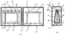
Fig. 5 represents an example of such carrying device.Fig. 5 (a) is for to watch the schematic cutaway view of vacuum chamber 10 in-to-ins along the conveyance direction.Inside at vacuum chamber 10, along the conveyance path, be laid with bearing 12 and U font guiding parts 15, described bearing 12 supporting guiding keep the substrate tray (substrate holder) 23 of glass substrates, and described U font guiding parts 15 leads to the substrate tray top in the noncontact mode.By actuator 16, the bearing rotation, substrate tray 23 is vertical shifting on bearing 12.
The guiding parts 15 of this U font is provided with according to the mode around the top of substrate tray, as shown in the part enlarged drawing of Fig. 5 (b), in the inboard of guiding parts, two magnet 16a, 16b is installed.On the other hand, on substrate tray 23, according to the mode of repelling two magnet 16a, 16b, magnet 26 is installed, according to repulsive force by magnet 16a, 16b and magnet 26, lead to substrate tray being positioned at the mode at the guiding parts 15 in-to-in centers of U font at ordinary times in the top of substrate tray.By adopting the guiding mechanism of such non-contact structure, can suppress the generation of the granulation of substrate top, in addition, conveyance substrate tray stably.
Equally, as the guiding mechanism that utilizes magnet, also disclose following transport mechanism, it is provided with according to the mode that the magnet of the magnet of substrate tray and its both sides attracts each other.
Patent documentation 1:JP spy opens flat 10-120171 document
The real fair 7-435 document of patent documentation 2:JP
But, if substrate size increases, in addition, follow this situation, the weight of substrate tray increases, and then knows that from the carrying device (TOHKEMY is put down-the 10-120171 document) in past shown in Figure 5 the swing of substrate tray top, vibration become big, in case produce vibration, then do not stop easily and continue chronically.Know also that in addition this vibration can damage bearing, shortens its life-span, and the granulation generating capacity of bearing portion is increased, vacuum chamber is polluted.So, in order to suppress the generation of granulation, must reduce the conveyance speed of substrate tray, consequently, the throughput of in fact having to sacrifice.
In addition, utilize in the carrying device (JP real fair 7-435 document) of guiding mechanism of suction of magnet, also have identical problem in employing.In this occasion, if have also that substrate tray tilts and surpass to a certain degree, the situation of the attraction of one in the magnet of substrate tray and the guiding parts then is if be provided for preventing the parts of this situation, then have because of the collision between these parts and the substrate tray, produce the problem of dust.
Summary of the invention
The object of the invention be to provide a kind of base board delivery device, but it is the carrying device of high speed conveyance large substrate, can suppress the swing of substrate tray, and then suppresses the generation of dust, does not pollute atmosphere, can realize stable high speed conveyance.
Base board delivery device of the present invention is along the conveyance path conveyance substrate in the vacuum chamber, this base board delivery device is by the carrier that the substrate tray that keeps substrate is installed, the carrier transport mechanism of this carrier of conveyance, with the carrier guiding mechanism formation that in the noncontact mode is led in the top of above-mentioned carrier along the conveyance path, it is characterized in that in above-mentioned guiding mechanism, first row's magnet and second series magnet are provided with according to the mode that attracts each other, this first row magnet is the one or more magnet on the top that is installed on above-mentioned carrier along the conveyance direction, substantially vertically magnetization, this second series magnet is above or below this first row magnet, spacing according to the rules is spaced away, along the conveyance path, fixing and be installed on one or more magnet in the vacuum chamber, substantially vertically magnetization.Additional features is that according to perpendicular to the conveyance direction between adjacent rows of magnets, many rows are provided with first row's magnet and the second series magnet in the opposite mode of the direction of magnetization.
Resemble so above-mentionedly, be installed on first on carrier row magnet,, thus, can realize more stable carrier conveyance with fixing and second series magnet that be installed in the vacuum chamber is provided with according to the mode that attracts each other up and down.
In addition, be arranged to more than two rows according to the alternately opposite mode of the direction of magnetization by making corresponding first and second row's magnet, then can be between first and second row's magnet of facing, effect suction, between first and second oblique row's magnet, the effect repulsive force.Consequently, though application force along with the situation of the perpendicular directive effect of conveyance direction under, the repulsive force between suction between the rows of magnets of facing and the oblique rows of magnets acts on still stackablely, can prevent from effectively to depart from the conveyance path.In addition, even because of certain reason, act on bigger power, substrate tray dislocation produces under the situation of swing, vibration, but these swings, vibration still finish within a short period of time, still can suppress the generation of granulation with doing one's utmost.
In addition, be arranged at stable self-support structure on the carrier by adopting two substrate trays itself with symmetric mode, conveyance stability further improves.
Best, be fixed in the top that second series magnet in the above-mentioned vacuum chamber is arranged at first row's magnet of above-mentioned carrier.By adopting above-mentioned scheme, magnetic force can along on put on the direction of stating carrier and act on, can reduce to act on the load on the bearing of supporting carrier deadweight.
Also have, the invention is characterized in that the mode that a plurality of magnet clipping rooies in above-mentioned first row's magnet and/or the second series magnet separate installs.
The invention is characterized in that the aforesaid substrate pallet has opening, this opening is used for the opposition side from treated side, and substrate is heated.Best, the relative vertical direction of afore mentioned rules angle is in 0.5~3 ° scope.
By according to the angle in this scope, the installation base plate pallet can further improve conveyance stability.In addition, in this angle in the occasion more than 0.5 °, can eliminate the vibration of substrate, the relative accident that flies out of substrate tray, in addition, in order to carry out furnace run etc. from inner face side, in substrate tray, offer the occasion of opening, by making angle below 3 °, can prevent the deflection of substrate itself, can carry out the higher film forming processing of homogeneity etc.Particularly, being suitable for the length of side is square substrate more than 1 meter.
The invention is characterized in that above-mentioned carrier is according to above-mentioned two carriers that the opposed facing mode of substrate tray is installed, the value that obtains after the length of resistance divided by the substrate tray of conveyance direction of the magnet of the power of the direction that the conveyance direction at itself and this carrier top is perpendicular is provided with above-mentioned first row's magnet and the second series magnet in the mode of 5.9~102.9 Newton/meter.By above-mentioned magnet setting, not the swing etc. situation under, the substrate of conveyance various sizes stably.
As described above,, can in the time of vibration, carry out high-revolving conveyance in the swing that suppresses substrate tray according to the present invention.So, can be under the situation that does not reduce throughput, the increase of the size of reply substrate.In addition, suppress the swing of substrate tray, vibration, even and producing this swing, under the situation of vibration, because decay at once still suppresses the generation of granulation.Consequently, can be used for the manufacturing of more high-precision telltale.In addition, because carrier adopts two substrate tray bonded assembly self-support results, so conveyance stability further improves, in addition, handle when can carry out two substrates, productivity also further improves.
Description of drawings
Fig. 1 has the scheme drawing of an example of vacuum treatment device of the base board delivery device of embodiment 1 for expression;
Fig. 2 is the part enlarged drawing of the carrier top perimeter portion of Fig. 1;
Fig. 3 is the scheme drawing of the guiding mechanism of the carrying device of expression embodiment 2;
Fig. 4 is the scheme drawing of the base board delivery device of expression embodiment 3;
Fig. 5 is the scheme drawing of an example of expression base board delivery device in the past.
The explanation of label
Label 15 expression guiding partss;
Label 16 expression actuators;
Label 26 expression magnet;
The label 40 expression families of power and influence.
The specific embodiment
Below by enumerating embodiment, base board delivery device of the present invention is carried out more concrete description.
Embodiment 1
Fig. 1 has the scheme drawing of an example of vacuum treatment device of the base board delivery device of embodiment 1 for expression.Fig. 1 (a) be from the perpendicular direction of conveyance direction, watch the in-to-in scheme drawing of vacuum treatment device, Fig. 1 (b) be along the A-A ' line among Fig. 1 (a) to view;
As shown in Fig. 1 (a), vacuum processing chamber 10,10 ' connect by the family of power and influence 40, in each vacuum processing chamber, the bearing 12 that supporting has the carrier 20 of two substrate trays 23 lays along the conveyance path with the second series magnet 14 that is used for being led in the top of carrier 20.Second series magnet 14 is arranged on the supporting member 13 of the pillar 11 that is fixed in the vacuum chamber.
Each substrate tray is according to relative vertical direction, and the mode with predetermined angular is installed.Here, in the occasion more than 1 meter, best in the length on one side of substrate, above-mentioned angle is more than 0.5 °, thus, prevents the flying out of substrate in the conveyance, can stablize conveyance (such as, 500~600 mm/second) at a high speed.In addition, owing on the substrate tray 23 of present embodiment, offer opening 24, so that substrate is heated, so if angle increases, in peristome substrate generation deflection, above-mentioned like this angle is preferably in below 3 ° from the inboard.
Fig. 2 represents to be installed on the setting of row's magnet 22 of first on link 21 and the supporting member 13 and second series magnet 14.Fig. 2 is the part enlarged drawing of Fig. 1, and as shown in the figure, first row's magnet 22 and second series magnet 14 are vertical direction according to magnetization, and the mode that attracts each other is provided with.Two rows are arranged to the perpendicular parallel mode of direction of conveyance direction in first row's magnet (with second series magnet) edge, and the direction of magnetization of adjacent magnets row 22a and 22b (14a and 14b) is opposite.
By forming such setting, the direction of magnetization is between the rows of magnets of facing, promptly, between rows of magnets 14a and 22a and 14b and the 22b, effect has suction, between adjacent rows of magnets, promptly, between rows of magnets 14a and 22b and 14b and 22a, effect has repulsive force, by the Overlay of two kinds power, along second series magnet, carrier is successfully led.
Here, the spacing between first row magnet 22 and the second series magnet 14 determines suitably that according to the kind of the size (weight of carrier) of conveyance speed, substrate and the magnet that adopted common, this spacing is in 1~10 millimeter scope.In addition, in first and second row's magnet, the spacing between the adjacent rows of magnets (22a and 22b and 14a and 14b) also determines that according to identical mode it is usually in 0~10 millimeter scope.
Specifically describe the carrying device that adopts as shown in Figure 1 below and come the conveyance substrate, heated substrates under vacuum condition carries out the concrete scheme case that film forming is handled.
In the unshowned in the drawings substrate load chamber, length (conveyance direction) is 1.7 meters, highly be 1.63 meters, thickness is that 15 millimeters aluminum base plate pallet 23 is with the glass substrate 30 of 2 ° of bevelled modes by link 21 and on the bonded assembly carrier 20, being equipped with two 1.3 (conveyance direction) * 1.1 meters (thickness is 0.5 millimeter).At this moment, carrier single-piece weight is about 200 kilograms, still, owing to form relative conveyance path, keeps the absolute construction of symmetry, so by bearing, supporting stably.
This carrier conveyance to heating chamber 10, by the lamp temperature booster, is heated to 250 ℃ with glass substrate 30.Then, open the family of power and influence 40, conveyance to film forming room 10 ', carry out exhaust, until 10
-5Pa by heat dump, remains on set point of temperature with glass substrate, sends into gas simultaneously, and target is connected High frequency power, and the time is carried out sputter according to the rules.After film forming, the carrier conveyance to non-load chamber (not shown), is recycled substrate, end process.Carry out this step repeatedly, thus, serially the polylith substrate is carried out film forming and handle.
In addition, in the bottom of substrate tray, form the straight line forwarder along the conveyance direction, be arranged in the vacuum chamber with its ingear driven wheel, by the rotation of driven wheel, carrier moves, though this point is not shown in the drawings.As transport mechanism, except the mechanism of such rack pinion type, also can be fit to adopt such as, the disclosed magnetic-type of TOHKEMY 2002-8226 document is captured the mechanism of type.
In the present embodiment, adopt a plurality of ferrite based magnet sheets (20 * 15 * 40 millimeters), form first and second row's magnet.That is, as second series magnet, according to opening with 5 millimeters intervals, the mutually opposite mode of the direction of magnetization is provided with two flat thin magnets, and it is supported on the supporting member 13 in the scope of the length of vacuum chamber continuously.On the other hand,, according to 5 millimeters spacing, two above-mentioned flat thin magnets are set equally,, this flat thin magnet are installed according to various spacings along the conveyance direction as first row's magnet.
Like this,, change the spacing of the conveyance direction of the flat thin magnet on the carrier 20, adjust suction and repulsive force between the above-mentioned magnet, carry out the high speed conveyance experiment of 500 mm/second according to various values.In addition, consequently,, then can swing, vibrate and do not have stable conveyance substantially if adopt the magnet scheme of resistance more than 10 newton with the power F (with reference to Fig. 1 (b)) of the perpendicular direction of the conveyance direction at carrier top.Here, resistance refers on link 21 hook is set, by spring balance, along stretch the expression value of the spring balance when first and second row's magnet stagger according to 0.5 millimeter abreast with the perpendicular direction of conveyance direction.
Then, the carrier to the processing that is used for more large-scale substrate carries out same experiment, obtains and swings, vibrates and do not have the resistance of the magnet of stable conveyance substantially.In addition, the thickness of substrate tray is 15 millimeters.Its result comes together in the table 1 with above-mentioned example.
Table 1
| Substrate (rice) | 1.0×1.3 | 1.3×1.5 | 1.8×2.2 |
| Substrate tray (rice) | 1.7×1.63 | 1.8×1.83 | 2.4×2.53 |
| Magnet resistance (newton) | 10~175 | 11~185 | 14~247 |
| Magnet resistance/pallet length (Newton/meter) | 5.9~102.9 | 5.8~102.9 | 5.8~102.9 |
As shown in table 1, know that the resistance that is used to guarantee the magnet of stable conveyance is followed the substrate tray size and increased, still, the value that this resistance obtains divided by the pallet length of conveyance direction is in essentially identical scope.So according to irrelevant with the size of substrate tray, the magnet resistance is divided by the mode of value in the scope of 5.9~102.9 Newton/meter of pallet length, the select magnet structure, thus, the substrate of conveyance various sizes stably.
In addition,, first and second row's magnet needn't be set continuously, can cut down the magnet cost significantly as its result.In addition, here higher limit (102.9 Newton/meter) is ground very close to each other, the value the when rare earth element magnet of Sm-Co system is set in the scope of the total length of carrier.
On the other hand, if use carrier continuously, then according to circumstances, the temperature with magnet rises to 300~350 ℃ situation.Owing to the magnetic force of magnet is followed the rising of temperature and descended, the structure of magnet, be provided with and design according to the mode of this reduction amount of estimation.Such as, under 350 ℃ condition 10 newton in order to make above-mentioned resistance, the resistance that then necessarily requires room temperature (20 ℃) is 60 newton's magnet arrangement, setting.
In addition,, then have the gas of discharging, film formation space is polluted, can't obtain required membranous situation by from magnet if the temperature of magnet rises.So, best in order to eject influence from the gaseous emission of magnet, magnet with sealing means be received in nonmagnetic material (such as, internal tank SUS304) is installed on it on internal vacuum chamber and the carrier.
Embodiment 2
Below with reference to Fig. 2, embodiment of the present invention is described.
Present embodiment is shown in Figure 3 as the enlarged drawing of link periphery, second series magnet (14a ..., 14f) and first row magnet (22a ..., 22f) be respectively six occasions of arranging, thus, can carry out more stable carrier conveyance.That is, the rows of magnets number is increased, further increase with the restoring force of the resistance of the power (F) of the perpendicular direction of conveyance direction and the occasion that departs from, conveyance stability improves.
Embodiment 3
Fig. 4 represents the 3rd embodiment of the present invention.Fig. 4 is the conveyance direction towards carrier, watches the scheme drawing of internal vacuum chamber.
In the present embodiment, supporting member 13 is arranged on the top board of vacuum chamber 10, at its bottom face, multi-row second series magnet is installed, and ranked first the top end face that row's magnet is installed on carrier link 21 more.Except that going out, other aspect is identical with embodiment 1 and 2.That is, the direction of magnetization of rows of magnets is vertical direction, and between the adjacent rows of magnets, the above-mentioned direction of magnetization is opposite.In addition, between the rows of magnets of facing in supporting member 13 and link 21, effect has suction, and between adjacent rows of magnets, effect has the mode of repulsive force to be provided with.
By forming such magnet setting, because on carrier, the power that effect is carried on having by magnet upward is so reduce to act on load on the bearing that supports carrier.Consequently, not only the life-span of bearing prolongs, and can prevent the generation from the bearing granulation, carries out more high-quality processing.
In above embodiment, as carrier, adopt by link, be connected and fixed substrate tray, support the bottom of each substrate tray, it is carried out the scheme of conveyance, still, the invention is not restricted to this, also can be used for the occasion of a substrate.In addition, equally for the carrier transport mechanism, except the mechanism of above-mentioned rack pinion type, also can be the type of direct drive bearing, the line motor conveyer of magnetic force come-up type etc., any transport mechanism.
In addition, the kind of magnet can suitably be selected according to the treatment conditions of the condition of conveyance speed, temperature etc., still, such as, except adopting above-mentioned ferrite based magnet, Sm-Co based rare earth magnet, also can adopt Nd-Fe-B based rare earth magnet etc.In addition, in the above-described embodiments, adopt the magnet scheme of the demagnetization of the magnet of having considered heating in advance, still, also can adopt the scheme of the cooling of carrying out magnet.
Claims (8)
1. carrying device that is used for the conveyance substrate, this base board delivery device is used in vacuum chamber along conveyance path conveyance substrate, this base board delivery device is by the carrier that substrate tray is installed, the carrier transport mechanism of this carrier of conveyance, with along the conveyance path, the carrier guiding mechanism that is led in the top of above-mentioned carrier in the noncontact mode constitutes, and it is characterized in that:
Above-mentioned guiding mechanism is made of first row's magnet and second series magnet, this first row magnet is installed on the top of above-mentioned carrier along the conveyance direction, this second series magnet is above or below this first row magnet, spacing according to the rules and first row's magnet are spaced apart, are mounted in the vacuum chamber along the conveyance path;
Above-mentioned first row's magnet and second series magnet are provided with according to the mode that attracts each other, and all are to be made of substantially vertically magnetized one or more magnet.
2. the carrying device that is used for the conveyance substrate according to claim 1 is characterized in that: according to being provided with perpendicular to the conveyance direction, and between adjacent rows of magnets, many rows are provided with first row's magnet and the second series magnet in the opposite mode of the direction of magnetization.
3. the carrying device that is used for the conveyance substrate according to claim 1 is characterized in that: above-mentioned second series magnet is arranged at the top of above-mentioned first row's magnet.
4. the carrying device that is used for the conveyance substrate according to claim 2 is characterized in that: above-mentioned second series magnet is arranged at the top of first row's magnet.
5. according to any one the described carrying device that is used for the conveyance substrate in the claim 1~4, it is characterized in that: a plurality of magnet in above-mentioned first row's magnet and/or the second series magnet are installed according to isolated mode.
6. according to any one the described carrying device that is used for the conveyance substrate in the claim 1~4, it is characterized in that: the aforesaid substrate pallet has opening, and this opening is used for the opposition side from treated side, and substrate is heated.
7. according to any one the described carrying device that is used for the conveyance substrate in the claim 1~4, it is characterized in that: the aforesaid substrate pallet is 0.5~3 ° angle with relative vertical direction, is installed on above-mentioned carrier.
8. according to any one the described carrying device that is used for the conveyance substrate in the claim 1~4, it is characterized in that: above-mentioned carrier is according to above-mentioned two carriers that the opposed facing mode of substrate tray is installed, at this carrier top, relatively the value that obtains after the length of resistance divided by the substrate tray of conveyance direction perpendicular to the magnet of the power (F) of conveyance direction is provided with above-mentioned first row's magnet and the second series magnet in the mode of 5.9~102.9 Newton/meter.
Applications Claiming Priority (3)
| Application Number | Priority Date | Filing Date | Title |
|---|---|---|---|
| JP2004-105072 | 2004-03-31 | ||
| JP2004105072A JP4471708B2 (en) | 2004-03-31 | 2004-03-31 | Substrate transfer device |
| JP2004105072 | 2004-03-31 |
Publications (2)
| Publication Number | Publication Date |
|---|---|
| CN1676445A CN1676445A (en) | 2005-10-05 |
| CN1676445B true CN1676445B (en) | 2011-06-08 |
Family
ID=35049218
Family Applications (1)
| Application Number | Title | Priority Date | Filing Date |
|---|---|---|---|
| CN2005100598529A Active CN1676445B (en) | 2004-03-31 | 2005-03-31 | Substrate moving device |
Country Status (4)
| Country | Link |
|---|---|
| JP (1) | JP4471708B2 (en) |
| KR (1) | KR101088665B1 (en) |
| CN (1) | CN1676445B (en) |
| TW (1) | TWI334401B (en) |
Families Citing this family (29)
| Publication number | Priority date | Publication date | Assignee | Title |
|---|---|---|---|---|
| EP1840242B1 (en) * | 2006-03-29 | 2011-06-29 | Applied Materials GmbH & Co. KG | Void apparatus with a movable guiding rail |
| JP2007269071A (en) * | 2006-03-30 | 2007-10-18 | Asyst Shinko Inc | Unmanned transporting device |
| KR101409524B1 (en) * | 2007-05-28 | 2014-06-20 | 엘지디스플레이 주식회사 | Apparatus for transferring substrates |
| KR101288599B1 (en) * | 2007-05-29 | 2013-07-22 | 엘지디스플레이 주식회사 | Apparatus for transferring substrates |
| US7770714B2 (en) | 2007-08-27 | 2010-08-10 | Canon Anelva Corporation | Transfer apparatus |
| JP4505002B2 (en) * | 2007-08-27 | 2010-07-14 | キヤノンアネルバ株式会社 | Transport device |
| DE102008015982B3 (en) | 2008-03-27 | 2009-07-30 | Grenzebach Maschinenbau Gmbh | Method and device for fixing and further transporting impact-sensitive plates in sputter coating systems, computer program for carrying out the method and machine-readable carrier for this purpose |
| US8226795B2 (en) * | 2009-02-03 | 2012-07-24 | Nordson Corporation | Magnetic clips and substrate holders for use in a plasma processing system |
| WO2011007753A1 (en) | 2009-07-14 | 2011-01-20 | キヤノンアネルバ株式会社 | Substrate processing device |
| CN101989005B (en) * | 2009-07-30 | 2013-08-14 | 北京京东方光电科技有限公司 | Structural substrate, conveying device and box pairing device |
| JP4745447B2 (en) * | 2010-02-04 | 2011-08-10 | キヤノンアネルバ株式会社 | Substrate transfer apparatus and vacuum processing apparatus |
| JP5731838B2 (en) * | 2010-02-10 | 2015-06-10 | キヤノンアネルバ株式会社 | Tray-type substrate transfer system, film forming method, and electronic device manufacturing method |
| CN102190156B (en) * | 2010-02-10 | 2014-06-25 | 佳能安内华股份有限公司 | Tray-type substrate conveying system, film formation method and manufacturing method of electronic device |
| JP5903429B2 (en) * | 2010-04-30 | 2016-04-13 | アプライド マテリアルズ インコーポレイテッドApplied Materials,Incorporated | Vertical in-line CVD system |
| CN101954625A (en) * | 2010-10-21 | 2011-01-26 | 湖南玉丰真空科学技术有限公司 | Workpiece fixture |
| TWI476139B (en) * | 2011-06-30 | 2015-03-11 | Sfa Engineering Corp | Apparatus for transferring substrates |
| JP2013021036A (en) * | 2011-07-08 | 2013-01-31 | Canon Anelva Corp | Transport device |
| KR101319785B1 (en) * | 2013-03-18 | 2013-10-18 | 주식회사 야스 | Apparatus for substrate transportation using electrostatic floating |
| CN103420165B (en) * | 2013-08-06 | 2015-09-02 | 中国电子科技集团公司第四十八研究所 | A kind of substrate transmission device |
| JP6092349B2 (en) * | 2014-11-27 | 2017-03-08 | アルバック コリア リミテッドUlvac Korea,Ltd. | Substrate transfer device |
| KR20160063969A (en) * | 2014-11-27 | 2016-06-07 | 한국알박(주) | Apparatus for transferring substrate |
| DE102015004582B4 (en) * | 2015-04-09 | 2017-02-09 | Mecatronix Ag | Device for holding, positioning and moving an object |
| CN104820306B (en) * | 2015-05-27 | 2018-01-26 | 京东方科技集团股份有限公司 | Stripping means and stepped construction, the display panel and display device of a kind of substrate |
| CN106044243B (en) * | 2016-07-08 | 2019-06-04 | 佛山格尼斯磁悬浮技术有限公司 | Panel vertical conveyor |
| WO2018166636A1 (en) * | 2017-03-17 | 2018-09-20 | Applied Materials, Inc. | Apparatus for vacuum processing of a substrate, system for vacuum processing of a substrate, and method for transportation of a substrate carrier and a mask carrier in a vacuum chamber |
| CN108519693B (en) * | 2018-04-16 | 2021-10-29 | 京东方科技集团股份有限公司 | Substrate alignment device, substrate and substrate alignment method |
| KR102090645B1 (en) * | 2018-08-27 | 2020-03-18 | 엘지전자 주식회사 | Conveying apparatus |
| JP7242414B2 (en) * | 2019-05-08 | 2023-03-20 | 株式会社アルバック | Vacuum transfer device and film forming device |
| CN110453200A (en) * | 2019-08-16 | 2019-11-15 | 星弧涂层新材料科技(苏州)股份有限公司 | The longitudinal travelling bogie of sheet material and vapor deposition apparatus |
Citations (4)
| Publication number | Priority date | Publication date | Assignee | Title |
|---|---|---|---|---|
| US5133285A (en) * | 1990-11-15 | 1992-07-28 | Leybold Aktiengesellschaft | Apparatus for transporting substrates |
| US5909995A (en) * | 1996-10-15 | 1999-06-08 | Balzers Aktiengesellschaft | Transport device for workpieces in a vacuum system |
| CN1272960A (en) * | 1997-09-30 | 2000-11-08 | 塞米图尔公司 | Semiconductor processing apparatus having linear conveyor system |
| US6471459B2 (en) * | 1998-05-20 | 2002-10-29 | Applied Komatsu Technology, Inc. | Substrate transfer shuttle having a magnetic drive |
Family Cites Families (3)
| Publication number | Priority date | Publication date | Assignee | Title |
|---|---|---|---|---|
| JP2687306B2 (en) * | 1994-05-16 | 1997-12-08 | 株式会社エイコー・エンジニアリング | Substrate transfer device in vacuum system |
| JP2000177842A (en) * | 1998-12-10 | 2000-06-27 | Mitsubishi Heavy Ind Ltd | Carrying device and vacuum processing device |
| JP3842935B2 (en) * | 1999-10-22 | 2006-11-08 | 三菱重工業株式会社 | Trayless diagonal substrate transfer device |
-
2004
- 2004-03-31 JP JP2004105072A patent/JP4471708B2/en not_active Expired - Lifetime
-
2005
- 2005-01-31 TW TW094102869A patent/TWI334401B/en active
- 2005-02-03 KR KR1020050009809A patent/KR101088665B1/en active IP Right Grant
- 2005-03-31 CN CN2005100598529A patent/CN1676445B/en active Active
Patent Citations (4)
| Publication number | Priority date | Publication date | Assignee | Title |
|---|---|---|---|---|
| US5133285A (en) * | 1990-11-15 | 1992-07-28 | Leybold Aktiengesellschaft | Apparatus for transporting substrates |
| US5909995A (en) * | 1996-10-15 | 1999-06-08 | Balzers Aktiengesellschaft | Transport device for workpieces in a vacuum system |
| CN1272960A (en) * | 1997-09-30 | 2000-11-08 | 塞米图尔公司 | Semiconductor processing apparatus having linear conveyor system |
| US6471459B2 (en) * | 1998-05-20 | 2002-10-29 | Applied Komatsu Technology, Inc. | Substrate transfer shuttle having a magnetic drive |
Also Published As
| Publication number | Publication date |
|---|---|
| TWI334401B (en) | 2010-12-11 |
| TW200533582A (en) | 2005-10-16 |
| JP4471708B2 (en) | 2010-06-02 |
| JP2005289556A (en) | 2005-10-20 |
| KR20060041618A (en) | 2006-05-12 |
| CN1676445A (en) | 2005-10-05 |
| KR101088665B1 (en) | 2011-12-01 |
Similar Documents
| Publication | Publication Date | Title |
|---|---|---|
| CN1676445B (en) | Substrate moving device | |
| JP4745447B2 (en) | Substrate transfer apparatus and vacuum processing apparatus | |
| KR101409524B1 (en) | Apparatus for transferring substrates | |
| JP6165992B2 (en) | Magnetic levitation transport device | |
| KR101288599B1 (en) | Apparatus for transferring substrates | |
| KR101386685B1 (en) | Apparatus for processing substrate | |
| JP2005289556A5 (en) | ||
| KR20080014578A (en) | Substrate transport device | |
| KR101271112B1 (en) | Vaccum processing apparatus | |
| JP2007214539A (en) | Substrate transporting device | |
| KR20200043537A (en) | Apparatus for transportation of a substrate, apparatus for vacuum processing of a substrate, and method for maintenance of a magnetic levitation system | |
| JP2009208909A (en) | Noncontact conveying device | |
| CN108368605A (en) | Vacuum treatment installation | |
| CN100517629C (en) | Process system and device for transporting substrates | |
| CN103283011B (en) | Film formation device | |
| CN109690751B (en) | Substrate processing apparatus | |
| KR20180056990A (en) | Film Deposition Apparatus and Method | |
| JP2015016537A (en) | Fixture and fixing device for component, and fixing transfer carrier | |
| JP6647492B2 (en) | Non-contact drive transmission | |
| CN108966661B (en) | Apparatus for vacuum processing of substrates, system for manufacturing of devices with organic material, and method for sealing an opening connecting two pressure areas | |
| KR20060134363A (en) | Apparatus of inclined type carrier transfer | |
| KR102359244B1 (en) | Film Deposition Method | |
| JP2011029540A (en) | Vacuum processing device, substrate conveying device, and film forming method | |
| CN108217207A (en) | Electromagnetic levitation type base plate transfer device | |
| JP2009051608A (en) | Conveying device |
Legal Events
| Date | Code | Title | Description |
|---|---|---|---|
| C06 | Publication | ||
| PB01 | Publication | ||
| C10 | Entry into substantive examination | ||
| SE01 | Entry into force of request for substantive examination | ||
| C14 | Grant of patent or utility model | ||
| GR01 | Patent grant |