CN1705732A - Oxonitride phosphor and method for production thereof, and luminescent device using the oxonitride phosphor - Google Patents
Oxonitride phosphor and method for production thereof, and luminescent device using the oxonitride phosphor Download PDFInfo
- Publication number
- CN1705732A CN1705732A CNA2003801016488A CN200380101648A CN1705732A CN 1705732 A CN1705732 A CN 1705732A CN A2003801016488 A CNA2003801016488 A CN A2003801016488A CN 200380101648 A CN200380101648 A CN 200380101648A CN 1705732 A CN1705732 A CN 1705732A
- Authority
- CN
- China
- Prior art keywords
- light
- phosphor
- oxynitride
- group
- emitting device
- Prior art date
- Legal status (The legal status is an assumption and is not a legal conclusion. Google has not performed a legal analysis and makes no representation as to the accuracy of the status listed.)
- Granted
Links
- OAICVXFJPJFONN-UHFFFAOYSA-N Phosphorus Chemical compound [P] OAICVXFJPJFONN-UHFFFAOYSA-N 0.000 title claims abstract description 543
- 238000004519 manufacturing process Methods 0.000 title claims description 49
- 230000005284 excitation Effects 0.000 claims abstract description 119
- 239000012190 activator Substances 0.000 claims abstract description 70
- 229910052791 calcium Inorganic materials 0.000 claims abstract description 46
- 229910052712 strontium Inorganic materials 0.000 claims abstract description 46
- 229910052788 barium Inorganic materials 0.000 claims abstract description 42
- 239000013078 crystal Substances 0.000 claims abstract description 39
- 229910052710 silicon Inorganic materials 0.000 claims abstract description 36
- 229910052761 rare earth metal Inorganic materials 0.000 claims abstract description 31
- 229910052725 zinc Inorganic materials 0.000 claims abstract description 28
- 229910052732 germanium Inorganic materials 0.000 claims abstract description 26
- 229910052799 carbon Inorganic materials 0.000 claims abstract description 24
- 229910052719 titanium Inorganic materials 0.000 claims abstract description 23
- 229910052749 magnesium Inorganic materials 0.000 claims abstract description 22
- 229910021480 group 4 element Inorganic materials 0.000 claims abstract description 20
- 229910052735 hafnium Inorganic materials 0.000 claims abstract description 20
- 229910052718 tin Inorganic materials 0.000 claims abstract description 20
- 229910052726 zirconium Inorganic materials 0.000 claims abstract description 18
- 229910052790 beryllium Inorganic materials 0.000 claims abstract description 13
- 239000000463 material Substances 0.000 claims description 132
- 150000004767 nitrides Chemical class 0.000 claims description 116
- 239000000203 mixture Substances 0.000 claims description 109
- 239000002994 raw material Substances 0.000 claims description 87
- 238000000295 emission spectrum Methods 0.000 claims description 84
- 238000002156 mixing Methods 0.000 claims description 82
- 239000004065 semiconductor Substances 0.000 claims description 70
- 150000001875 compounds Chemical class 0.000 claims description 36
- 229910052693 Europium Inorganic materials 0.000 claims description 35
- 229910052733 gallium Inorganic materials 0.000 claims description 33
- 238000011156 evaluation Methods 0.000 claims description 32
- 229910052760 oxygen Inorganic materials 0.000 claims description 26
- 238000011161 development Methods 0.000 claims description 25
- 238000001228 spectrum Methods 0.000 claims description 24
- 229910052757 nitrogen Inorganic materials 0.000 claims description 23
- 229910052796 boron Inorganic materials 0.000 claims description 20
- IJGRMHOSHXDMSA-UHFFFAOYSA-N Atomic nitrogen Chemical compound N#N IJGRMHOSHXDMSA-UHFFFAOYSA-N 0.000 claims description 18
- 238000010304 firing Methods 0.000 claims description 17
- 229910052782 aluminium Inorganic materials 0.000 claims description 11
- 229910052738 indium Inorganic materials 0.000 claims description 8
- QVGXLLKOCUKJST-UHFFFAOYSA-N atomic oxygen Chemical compound [O] QVGXLLKOCUKJST-UHFFFAOYSA-N 0.000 claims description 7
- 239000001301 oxygen Substances 0.000 claims description 7
- 150000002910 rare earth metals Chemical class 0.000 abstract description 2
- 235000019646 color tone Nutrition 0.000 description 101
- VYPSYNLAJGMNEJ-UHFFFAOYSA-N silicon dioxide Inorganic materials O=[Si]=O VYPSYNLAJGMNEJ-UHFFFAOYSA-N 0.000 description 69
- 229910052581 Si3N4 Inorganic materials 0.000 description 48
- -1 alkaline earth metal borate halogen Chemical class 0.000 description 45
- 239000000377 silicon dioxide Substances 0.000 description 44
- 229910052681 coesite Inorganic materials 0.000 description 42
- 229910052906 cristobalite Inorganic materials 0.000 description 42
- RSEIMSPAXMNYFJ-UHFFFAOYSA-N europium(III) oxide Inorganic materials O=[Eu]O[Eu]=O RSEIMSPAXMNYFJ-UHFFFAOYSA-N 0.000 description 42
- 229910052682 stishovite Inorganic materials 0.000 description 42
- 229910052905 tridymite Inorganic materials 0.000 description 42
- 239000000758 substrate Substances 0.000 description 40
- 238000009877 rendering Methods 0.000 description 39
- 229910002601 GaN Inorganic materials 0.000 description 36
- 238000000576 coating method Methods 0.000 description 36
- 239000011248 coating agent Substances 0.000 description 35
- 238000010586 diagram Methods 0.000 description 35
- 238000000034 method Methods 0.000 description 35
- 239000002245 particle Substances 0.000 description 33
- 238000006243 chemical reaction Methods 0.000 description 30
- 239000011777 magnesium Substances 0.000 description 30
- QGZKDVFQNNGYKY-UHFFFAOYSA-N Ammonia Chemical compound N QGZKDVFQNNGYKY-UHFFFAOYSA-N 0.000 description 28
- 238000000695 excitation spectrum Methods 0.000 description 26
- 239000012298 atmosphere Substances 0.000 description 24
- 239000011230 binding agent Substances 0.000 description 24
- 238000004020 luminiscence type Methods 0.000 description 22
- 229910052688 Gadolinium Inorganic materials 0.000 description 21
- 239000000843 powder Substances 0.000 description 20
- 229910019655 synthetic inorganic crystalline material Inorganic materials 0.000 description 20
- 229920005989 resin Polymers 0.000 description 19
- 239000011347 resin Substances 0.000 description 19
- 230000001965 increasing effect Effects 0.000 description 18
- 229910052594 sapphire Inorganic materials 0.000 description 18
- 239000010980 sapphire Substances 0.000 description 18
- 229910052727 yttrium Inorganic materials 0.000 description 18
- PZNSFCLAULLKQX-UHFFFAOYSA-N Boron nitride Chemical compound N#B PZNSFCLAULLKQX-UHFFFAOYSA-N 0.000 description 17
- 239000012299 nitrogen atmosphere Substances 0.000 description 17
- 238000010298 pulverizing process Methods 0.000 description 17
- 239000010936 titanium Substances 0.000 description 17
- 239000010931 gold Substances 0.000 description 16
- 229910052751 metal Inorganic materials 0.000 description 16
- 239000002184 metal Substances 0.000 description 16
- 239000003086 colorant Substances 0.000 description 15
- 229910052737 gold Inorganic materials 0.000 description 15
- 229910052582 BN Inorganic materials 0.000 description 14
- 229910016066 BaSi Inorganic materials 0.000 description 14
- 230000000052 comparative effect Effects 0.000 description 14
- 239000011521 glass Substances 0.000 description 14
- 238000002441 X-ray diffraction Methods 0.000 description 13
- 229910001940 europium oxide Inorganic materials 0.000 description 12
- AEBZCFFCDTZXHP-UHFFFAOYSA-N europium(3+);oxygen(2-) Chemical compound [O-2].[O-2].[O-2].[Eu+3].[Eu+3] AEBZCFFCDTZXHP-UHFFFAOYSA-N 0.000 description 12
- 239000010408 film Substances 0.000 description 12
- 239000000178 monomer Substances 0.000 description 11
- 229910004706 CaSi2 Inorganic materials 0.000 description 10
- PNEYBMLMFCGWSK-UHFFFAOYSA-N aluminium oxide Inorganic materials [O-2].[O-2].[O-2].[Al+3].[Al+3] PNEYBMLMFCGWSK-UHFFFAOYSA-N 0.000 description 10
- 239000010949 copper Substances 0.000 description 10
- 229910052744 lithium Inorganic materials 0.000 description 10
- 229910052700 potassium Inorganic materials 0.000 description 10
- 229910052708 sodium Inorganic materials 0.000 description 10
- 229910002704 AlGaN Inorganic materials 0.000 description 9
- 229910052784 alkaline earth metal Inorganic materials 0.000 description 9
- 229910021529 ammonia Inorganic materials 0.000 description 9
- PCHJSUWPFVWCPO-UHFFFAOYSA-N gold Chemical compound [Au] PCHJSUWPFVWCPO-UHFFFAOYSA-N 0.000 description 9
- SQGYOTSLMSWVJD-UHFFFAOYSA-N silver(1+) nitrate Chemical compound [Ag+].[O-]N(=O)=O SQGYOTSLMSWVJD-UHFFFAOYSA-N 0.000 description 9
- 229910004412 SrSi2 Inorganic materials 0.000 description 8
- 230000004888 barrier function Effects 0.000 description 8
- 239000000470 constituent Substances 0.000 description 8
- 230000000694 effects Effects 0.000 description 8
- 229910052747 lanthanoid Inorganic materials 0.000 description 8
- 150000002602 lanthanoids Chemical class 0.000 description 8
- BASFCYQUMIYNBI-UHFFFAOYSA-N platinum Chemical group [Pt] BASFCYQUMIYNBI-UHFFFAOYSA-N 0.000 description 8
- 230000008569 process Effects 0.000 description 8
- 239000002002 slurry Substances 0.000 description 8
- XCZXGTMEAKBVPV-UHFFFAOYSA-N trimethylgallium Chemical compound C[Ga](C)C XCZXGTMEAKBVPV-UHFFFAOYSA-N 0.000 description 8
- XLYOFNOQVPJJNP-UHFFFAOYSA-N water Chemical compound O XLYOFNOQVPJJNP-UHFFFAOYSA-N 0.000 description 8
- 229910016064 BaSi2 Inorganic materials 0.000 description 7
- 229910004709 CaSi Inorganic materials 0.000 description 7
- 229910052802 copper Inorganic materials 0.000 description 7
- 239000003822 epoxy resin Substances 0.000 description 7
- 239000012535 impurity Substances 0.000 description 7
- 229920000647 polyepoxide Polymers 0.000 description 7
- 229910052814 silicon oxide Inorganic materials 0.000 description 7
- 229910001868 water Inorganic materials 0.000 description 7
- 238000005303 weighing Methods 0.000 description 7
- XKRFYHLGVUSROY-UHFFFAOYSA-N Argon Chemical compound [Ar] XKRFYHLGVUSROY-UHFFFAOYSA-N 0.000 description 6
- XEEYBQQBJWHFJM-UHFFFAOYSA-N Iron Chemical compound [Fe] XEEYBQQBJWHFJM-UHFFFAOYSA-N 0.000 description 6
- CDBYLPFSWZWCQE-UHFFFAOYSA-L Sodium Carbonate Chemical compound [Na+].[Na+].[O-]C([O-])=O CDBYLPFSWZWCQE-UHFFFAOYSA-L 0.000 description 6
- 238000010521 absorption reaction Methods 0.000 description 6
- AIYUHDOJVYHVIT-UHFFFAOYSA-M caesium chloride Chemical compound [Cl-].[Cs+] AIYUHDOJVYHVIT-UHFFFAOYSA-M 0.000 description 6
- 238000005530 etching Methods 0.000 description 6
- OGPBJKLSAFTDLK-UHFFFAOYSA-N europium atom Chemical compound [Eu] OGPBJKLSAFTDLK-UHFFFAOYSA-N 0.000 description 6
- 239000007789 gas Substances 0.000 description 6
- YBMRDBCBODYGJE-UHFFFAOYSA-N germanium dioxide Chemical compound O=[Ge]=O YBMRDBCBODYGJE-UHFFFAOYSA-N 0.000 description 6
- 229910052736 halogen Inorganic materials 0.000 description 6
- 238000005286 illumination Methods 0.000 description 6
- 229910052748 manganese Inorganic materials 0.000 description 6
- NUJOXMJBOLGQSY-UHFFFAOYSA-N manganese dioxide Chemical compound O=[Mn]=O NUJOXMJBOLGQSY-UHFFFAOYSA-N 0.000 description 6
- 238000005259 measurement Methods 0.000 description 6
- PXHVJJICTQNCMI-UHFFFAOYSA-N nickel Substances [Ni] PXHVJJICTQNCMI-UHFFFAOYSA-N 0.000 description 6
- BWHMMNNQKKPAPP-UHFFFAOYSA-L potassium carbonate Chemical compound [K+].[K+].[O-]C([O-])=O BWHMMNNQKKPAPP-UHFFFAOYSA-L 0.000 description 6
- XZQYTGKSBZGQMO-UHFFFAOYSA-I rhenium pentachloride Chemical compound Cl[Re](Cl)(Cl)(Cl)Cl XZQYTGKSBZGQMO-UHFFFAOYSA-I 0.000 description 6
- FGDZQCVHDSGLHJ-UHFFFAOYSA-M rubidium chloride Chemical compound [Cl-].[Rb+] FGDZQCVHDSGLHJ-UHFFFAOYSA-M 0.000 description 6
- 238000004088 simulation Methods 0.000 description 6
- 239000000126 substance Substances 0.000 description 6
- 239000000853 adhesive Substances 0.000 description 5
- 230000001070 adhesive effect Effects 0.000 description 5
- 150000001342 alkaline earth metals Chemical class 0.000 description 5
- PSBUJOCDKOWAGJ-UHFFFAOYSA-N azanylidyneeuropium Chemical compound [Eu]#N PSBUJOCDKOWAGJ-UHFFFAOYSA-N 0.000 description 5
- 230000008859 change Effects 0.000 description 5
- 239000003795 chemical substances by application Substances 0.000 description 5
- 239000008187 granular material Substances 0.000 description 5
- 239000001257 hydrogen Substances 0.000 description 5
- 229910052739 hydrogen Inorganic materials 0.000 description 5
- 150000003949 imides Chemical class 0.000 description 5
- 239000011159 matrix material Substances 0.000 description 5
- 230000005855 radiation Effects 0.000 description 5
- 229920002050 silicone resin Polymers 0.000 description 5
- 229910052709 silver Inorganic materials 0.000 description 5
- 239000010409 thin film Substances 0.000 description 5
- VPSXHKGJZJCWLV-UHFFFAOYSA-N 2-[4-[2-(2,3-dihydro-1H-inden-2-ylamino)pyrimidin-5-yl]-3-(1-ethylpiperidin-4-yl)oxypyrazol-1-yl]-1-(2,4,6,7-tetrahydrotriazolo[4,5-c]pyridin-5-yl)ethanone Chemical compound C1C(CC2=CC=CC=C12)NC1=NC=C(C=N1)C=1C(=NN(C=1)CC(=O)N1CC2=C(CC1)NN=N2)OC1CCN(CC1)CC VPSXHKGJZJCWLV-UHFFFAOYSA-N 0.000 description 4
- 229910052692 Dysprosium Inorganic materials 0.000 description 4
- LFQSCWFLJHTTHZ-UHFFFAOYSA-N Ethanol Chemical compound CCO LFQSCWFLJHTTHZ-UHFFFAOYSA-N 0.000 description 4
- WMFOQBRAJBCJND-UHFFFAOYSA-M Lithium hydroxide Chemical compound [Li+].[OH-] WMFOQBRAJBCJND-UHFFFAOYSA-M 0.000 description 4
- 229910020056 Mg3N2 Inorganic materials 0.000 description 4
- 229910052779 Neodymium Inorganic materials 0.000 description 4
- 229910006360 Si—O—N Inorganic materials 0.000 description 4
- 229910052771 Terbium Inorganic materials 0.000 description 4
- GWEVSGVZZGPLCZ-UHFFFAOYSA-N Titan oxide Chemical compound O=[Ti]=O GWEVSGVZZGPLCZ-UHFFFAOYSA-N 0.000 description 4
- JLDSOYXADOWAKB-UHFFFAOYSA-N aluminium nitrate Chemical compound [Al+3].[O-][N+]([O-])=O.[O-][N+]([O-])=O.[O-][N+]([O-])=O JLDSOYXADOWAKB-UHFFFAOYSA-N 0.000 description 4
- 150000001408 amides Chemical class 0.000 description 4
- 238000004458 analytical method Methods 0.000 description 4
- 238000005253 cladding Methods 0.000 description 4
- 239000002019 doping agent Substances 0.000 description 4
- 239000010419 fine particle Substances 0.000 description 4
- 150000002367 halogens Chemical class 0.000 description 4
- 238000010438 heat treatment Methods 0.000 description 4
- 239000007788 liquid Substances 0.000 description 4
- 239000004973 liquid crystal related substance Substances 0.000 description 4
- 238000000465 moulding Methods 0.000 description 4
- 150000003839 salts Chemical class 0.000 description 4
- SCPYDCQAZCOKTP-UHFFFAOYSA-N silanol Chemical compound [SiH3]O SCPYDCQAZCOKTP-UHFFFAOYSA-N 0.000 description 4
- 229960001866 silicon dioxide Drugs 0.000 description 4
- HQVNEWCFYHHQES-UHFFFAOYSA-N silicon nitride Chemical compound N12[Si]34N5[Si]62N3[Si]51N64 HQVNEWCFYHHQES-UHFFFAOYSA-N 0.000 description 4
- 239000010944 silver (metal) Substances 0.000 description 4
- OGIDPMRJRNCKJF-UHFFFAOYSA-N titanium oxide Inorganic materials [Ti]=O OGIDPMRJRNCKJF-UHFFFAOYSA-N 0.000 description 4
- 229910014526 Ca2Si Inorganic materials 0.000 description 3
- UXVMQQNJUSDDNG-UHFFFAOYSA-L Calcium chloride Chemical compound [Cl-].[Cl-].[Ca+2] UXVMQQNJUSDDNG-UHFFFAOYSA-L 0.000 description 3
- 229910052684 Cerium Inorganic materials 0.000 description 3
- RYGMFSIKBFXOCR-UHFFFAOYSA-N Copper Chemical compound [Cu] RYGMFSIKBFXOCR-UHFFFAOYSA-N 0.000 description 3
- 229910052691 Erbium Inorganic materials 0.000 description 3
- 229910004042 HAuCl4 Inorganic materials 0.000 description 3
- 229910003865 HfCl4 Inorganic materials 0.000 description 3
- 229910052689 Holmium Inorganic materials 0.000 description 3
- 229910052765 Lutetium Inorganic materials 0.000 description 3
- 229910019752 Mg2Si Inorganic materials 0.000 description 3
- 229910052777 Praseodymium Inorganic materials 0.000 description 3
- 229910052772 Samarium Inorganic materials 0.000 description 3
- 229910052775 Thulium Inorganic materials 0.000 description 3
- 229910010298 TiOSO4 Inorganic materials 0.000 description 3
- 229920001807 Urea-formaldehyde Polymers 0.000 description 3
- 229910052769 Ytterbium Inorganic materials 0.000 description 3
- 229910008334 ZrO(NO3)2 Inorganic materials 0.000 description 3
- 229910052586 apatite Inorganic materials 0.000 description 3
- 229910052786 argon Inorganic materials 0.000 description 3
- 239000012300 argon atmosphere Substances 0.000 description 3
- 229910001626 barium chloride Inorganic materials 0.000 description 3
- WDIHJSXYQDMJHN-UHFFFAOYSA-L barium chloride Chemical compound [Cl-].[Cl-].[Ba+2] WDIHJSXYQDMJHN-UHFFFAOYSA-L 0.000 description 3
- 229910002113 barium titanate Inorganic materials 0.000 description 3
- JRPBQTZRNDNNOP-UHFFFAOYSA-N barium titanate Chemical compound [Ba+2].[Ba+2].[O-][Ti]([O-])([O-])[O-] JRPBQTZRNDNNOP-UHFFFAOYSA-N 0.000 description 3
- 230000015572 biosynthetic process Effects 0.000 description 3
- 229910052794 bromium Inorganic materials 0.000 description 3
- 229910052792 caesium Inorganic materials 0.000 description 3
- 239000001110 calcium chloride Substances 0.000 description 3
- 229910001628 calcium chloride Inorganic materials 0.000 description 3
- 239000000919 ceramic Substances 0.000 description 3
- 229910052801 chlorine Inorganic materials 0.000 description 3
- 238000009826 distribution Methods 0.000 description 3
- 238000007580 dry-mixing Methods 0.000 description 3
- 229910052731 fluorine Inorganic materials 0.000 description 3
- PDPJQWYGJJBYLF-UHFFFAOYSA-J hafnium tetrachloride Chemical compound Cl[Hf](Cl)(Cl)Cl PDPJQWYGJJBYLF-UHFFFAOYSA-J 0.000 description 3
- XLYOFNOQVPJJNP-ZSJDYOACSA-N heavy water Substances [2H]O[2H] XLYOFNOQVPJJNP-ZSJDYOACSA-N 0.000 description 3
- 239000011261 inert gas Substances 0.000 description 3
- 229910052740 iodine Inorganic materials 0.000 description 3
- 229910052742 iron Inorganic materials 0.000 description 3
- 229910000833 kovar Inorganic materials 0.000 description 3
- 229910052746 lanthanum Inorganic materials 0.000 description 3
- YIXJRHPUWRPCBB-UHFFFAOYSA-N magnesium nitrate Inorganic materials [Mg+2].[O-][N+]([O-])=O.[O-][N+]([O-])=O YIXJRHPUWRPCBB-UHFFFAOYSA-N 0.000 description 3
- 238000002844 melting Methods 0.000 description 3
- 238000002488 metal-organic chemical vapour deposition Methods 0.000 description 3
- 229910052759 nickel Inorganic materials 0.000 description 3
- TWNQGVIAIRXVLR-UHFFFAOYSA-N oxo(oxoalumanyloxy)alumane Chemical compound O=[Al]O[Al]=O TWNQGVIAIRXVLR-UHFFFAOYSA-N 0.000 description 3
- KADRTWZQWGIUGO-UHFFFAOYSA-L oxotitanium(2+);sulfate Chemical compound [Ti+2]=O.[O-]S([O-])(=O)=O KADRTWZQWGIUGO-UHFFFAOYSA-L 0.000 description 3
- VSIIXMUUUJUKCM-UHFFFAOYSA-D pentacalcium;fluoride;triphosphate Chemical compound [F-].[Ca+2].[Ca+2].[Ca+2].[Ca+2].[Ca+2].[O-]P([O-])([O-])=O.[O-]P([O-])([O-])=O.[O-]P([O-])([O-])=O VSIIXMUUUJUKCM-UHFFFAOYSA-D 0.000 description 3
- 229910000027 potassium carbonate Inorganic materials 0.000 description 3
- 238000002360 preparation method Methods 0.000 description 3
- 238000012545 processing Methods 0.000 description 3
- 239000011369 resultant mixture Substances 0.000 description 3
- 229910052702 rhenium Inorganic materials 0.000 description 3
- 229910052701 rubidium Inorganic materials 0.000 description 3
- 229910000029 sodium carbonate Inorganic materials 0.000 description 3
- 229910052596 spinel Inorganic materials 0.000 description 3
- 239000011029 spinel Substances 0.000 description 3
- 229910001631 strontium chloride Inorganic materials 0.000 description 3
- AHBGXTDRMVNFER-UHFFFAOYSA-L strontium dichloride Chemical compound [Cl-].[Cl-].[Sr+2] AHBGXTDRMVNFER-UHFFFAOYSA-L 0.000 description 3
- 229920001187 thermosetting polymer Polymers 0.000 description 3
- 229910052723 transition metal Inorganic materials 0.000 description 3
- 150000003624 transition metals Chemical class 0.000 description 3
- ONDPHDOFVYQSGI-UHFFFAOYSA-N zinc nitrate Inorganic materials [Zn+2].[O-][N+]([O-])=O.[O-][N+]([O-])=O ONDPHDOFVYQSGI-UHFFFAOYSA-N 0.000 description 3
- 239000004925 Acrylic resin Substances 0.000 description 2
- 229920000178 Acrylic resin Polymers 0.000 description 2
- 229910016034 BaGe2 Inorganic materials 0.000 description 2
- 229910005267 GaCl3 Inorganic materials 0.000 description 2
- 229910001218 Gallium arsenide Inorganic materials 0.000 description 2
- JMASRVWKEDWRBT-UHFFFAOYSA-N Gallium nitride Chemical compound [Ga]#N JMASRVWKEDWRBT-UHFFFAOYSA-N 0.000 description 2
- PSCMQHVBLHHWTO-UHFFFAOYSA-K Indium trichloride Inorganic materials Cl[In](Cl)Cl PSCMQHVBLHHWTO-UHFFFAOYSA-K 0.000 description 2
- 239000000020 Nitrocellulose Substances 0.000 description 2
- 239000005084 Strontium aluminate Substances 0.000 description 2
- 235000005811 Viola adunca Nutrition 0.000 description 2
- 235000013487 Viola odorata Nutrition 0.000 description 2
- 235000002254 Viola papilionacea Nutrition 0.000 description 2
- 229910007659 ZnSi2 Inorganic materials 0.000 description 2
- 229910045601 alloy Inorganic materials 0.000 description 2
- 239000000956 alloy Substances 0.000 description 2
- 150000004645 aluminates Chemical class 0.000 description 2
- 150000001450 anions Chemical class 0.000 description 2
- 238000000137 annealing Methods 0.000 description 2
- KGBXLFKZBHKPEV-UHFFFAOYSA-N boric acid Chemical compound OB(O)O KGBXLFKZBHKPEV-UHFFFAOYSA-N 0.000 description 2
- 150000001768 cations Chemical class 0.000 description 2
- 238000010276 construction Methods 0.000 description 2
- 229910052593 corundum Inorganic materials 0.000 description 2
- 239000006185 dispersion Substances 0.000 description 2
- 230000006870 function Effects 0.000 description 2
- UPWPDUACHOATKO-UHFFFAOYSA-K gallium trichloride Chemical compound Cl[Ga](Cl)Cl UPWPDUACHOATKO-UHFFFAOYSA-K 0.000 description 2
- 238000002248 hydride vapour-phase epitaxy Methods 0.000 description 2
- 239000004611 light stabiliser Substances 0.000 description 2
- 238000005121 nitriding Methods 0.000 description 2
- 229920001220 nitrocellulos Polymers 0.000 description 2
- 239000011368 organic material Substances 0.000 description 2
- 239000003960 organic solvent Substances 0.000 description 2
- 238000005375 photometry Methods 0.000 description 2
- 238000001020 plasma etching Methods 0.000 description 2
- 229910052697 platinum Inorganic materials 0.000 description 2
- 238000004062 sedimentation Methods 0.000 description 2
- 239000000741 silica gel Substances 0.000 description 2
- 229910002027 silica gel Inorganic materials 0.000 description 2
- 150000004760 silicates Chemical class 0.000 description 2
- RMAQACBXLXPBSY-UHFFFAOYSA-N silicic acid Chemical compound O[Si](O)(O)O RMAQACBXLXPBSY-UHFFFAOYSA-N 0.000 description 2
- 239000010703 silicon Substances 0.000 description 2
- 235000012239 silicon dioxide Nutrition 0.000 description 2
- 238000005245 sintering Methods 0.000 description 2
- 238000003980 solgel method Methods 0.000 description 2
- 239000007921 spray Substances 0.000 description 2
- 238000012916 structural analysis Methods 0.000 description 2
- 150000003568 thioethers Chemical class 0.000 description 2
- 238000002834 transmittance Methods 0.000 description 2
- 229910001845 yogo sapphire Inorganic materials 0.000 description 2
- MGYGFNQQGAQEON-UHFFFAOYSA-N 4-tolyl isocyanate Chemical compound CC1=CC=C(N=C=O)C=C1 MGYGFNQQGAQEON-UHFFFAOYSA-N 0.000 description 1
- 229910018632 Al0.05O2 Inorganic materials 0.000 description 1
- 229910017083 AlN Inorganic materials 0.000 description 1
- DKPFZGUDAPQIHT-UHFFFAOYSA-N Butyl acetate Natural products CCCCOC(C)=O DKPFZGUDAPQIHT-UHFFFAOYSA-N 0.000 description 1
- MHYQBXJRURFKIN-UHFFFAOYSA-N C1(C=CC=C1)[Mg] Chemical compound C1(C=CC=C1)[Mg] MHYQBXJRURFKIN-UHFFFAOYSA-N 0.000 description 1
- OKTJSMMVPCPJKN-UHFFFAOYSA-N Carbon Chemical compound [C] OKTJSMMVPCPJKN-UHFFFAOYSA-N 0.000 description 1
- 229910005833 GeO4 Inorganic materials 0.000 description 1
- UFHFLCQGNIYNRP-UHFFFAOYSA-N Hydrogen Chemical compound [H][H] UFHFLCQGNIYNRP-UHFFFAOYSA-N 0.000 description 1
- 229910002226 La2O2 Inorganic materials 0.000 description 1
- 229910020068 MgAl Inorganic materials 0.000 description 1
- 239000004698 Polyethylene Substances 0.000 description 1
- 239000004743 Polypropylene Substances 0.000 description 1
- 239000004793 Polystyrene Substances 0.000 description 1
- BLRPTPMANUNPDV-UHFFFAOYSA-N Silane Chemical compound [SiH4] BLRPTPMANUNPDV-UHFFFAOYSA-N 0.000 description 1
- XUIMIQQOPSSXEZ-UHFFFAOYSA-N Silicon Chemical compound [Si] XUIMIQQOPSSXEZ-UHFFFAOYSA-N 0.000 description 1
- BQCADISMDOOEFD-UHFFFAOYSA-N Silver Chemical compound [Ag] BQCADISMDOOEFD-UHFFFAOYSA-N 0.000 description 1
- 229910001128 Sn alloy Inorganic materials 0.000 description 1
- 229910003576 Sr0.5Ba0.5 Inorganic materials 0.000 description 1
- 229910003669 SrAl2O4 Inorganic materials 0.000 description 1
- 229910004122 SrSi Inorganic materials 0.000 description 1
- UCKMPCXJQFINFW-UHFFFAOYSA-N Sulphide Chemical compound [S-2] UCKMPCXJQFINFW-UHFFFAOYSA-N 0.000 description 1
- 244000154870 Viola adunca Species 0.000 description 1
- 240000009038 Viola odorata Species 0.000 description 1
- GANNOFFDYMSBSZ-UHFFFAOYSA-N [AlH3].[Mg] Chemical compound [AlH3].[Mg] GANNOFFDYMSBSZ-UHFFFAOYSA-N 0.000 description 1
- XAGFODPZIPBFFR-UHFFFAOYSA-N aluminium Chemical compound [Al] XAGFODPZIPBFFR-UHFFFAOYSA-N 0.000 description 1
- AYJRCSIUFZENHW-DEQYMQKBSA-L barium(2+);oxomethanediolate Chemical compound [Ba+2].[O-][14C]([O-])=O AYJRCSIUFZENHW-DEQYMQKBSA-L 0.000 description 1
- 239000012159 carrier gas Substances 0.000 description 1
- 229910052804 chromium Inorganic materials 0.000 description 1
- 239000011651 chromium Substances 0.000 description 1
- 238000004140 cleaning Methods 0.000 description 1
- 238000005520 cutting process Methods 0.000 description 1
- 230000002950 deficient Effects 0.000 description 1
- 239000008367 deionised water Substances 0.000 description 1
- 229910021641 deionized water Inorganic materials 0.000 description 1
- 238000013461 design Methods 0.000 description 1
- 230000006866 deterioration Effects 0.000 description 1
- 238000009792 diffusion process Methods 0.000 description 1
- XPPKVPWEQAFLFU-UHFFFAOYSA-J diphosphate(4-) Chemical compound [O-]P([O-])(=O)OP([O-])([O-])=O XPPKVPWEQAFLFU-UHFFFAOYSA-J 0.000 description 1
- 235000011180 diphosphates Nutrition 0.000 description 1
- 229910001650 dmitryivanovite Inorganic materials 0.000 description 1
- 235000013399 edible fruits Nutrition 0.000 description 1
- 239000007772 electrode material Substances 0.000 description 1
- 238000010894 electron beam technology Methods 0.000 description 1
- 230000001747 exhibiting effect Effects 0.000 description 1
- LNEPOXFFQSENCJ-UHFFFAOYSA-N haloperidol Chemical compound C1CC(O)(C=2C=CC(Cl)=CC=2)CCN1CCCC(=O)C1=CC=C(F)C=C1 LNEPOXFFQSENCJ-UHFFFAOYSA-N 0.000 description 1
- FUZZWVXGSFPDMH-UHFFFAOYSA-N hexanoic acid Chemical compound CCCCCC(O)=O FUZZWVXGSFPDMH-UHFFFAOYSA-N 0.000 description 1
- 150000002431 hydrogen Chemical class 0.000 description 1
- 229910010272 inorganic material Inorganic materials 0.000 description 1
- 239000011147 inorganic material Substances 0.000 description 1
- 229910001707 krotite Inorganic materials 0.000 description 1
- 238000012423 maintenance Methods 0.000 description 1
- 230000008018 melting Effects 0.000 description 1
- 150000002739 metals Chemical class 0.000 description 1
- 229910003465 moissanite Inorganic materials 0.000 description 1
- 239000012778 molding material Substances 0.000 description 1
- NJPPVKZQTLUDBO-UHFFFAOYSA-N novaluron Chemical compound C1=C(Cl)C(OC(F)(F)C(OC(F)(F)F)F)=CC=C1NC(=O)NC(=O)C1=C(F)C=CC=C1F NJPPVKZQTLUDBO-UHFFFAOYSA-N 0.000 description 1
- 230000003287 optical effect Effects 0.000 description 1
- KSOCVFUBQIXVDC-FMQUCBEESA-N p-azophenyltrimethylammonium Chemical compound C1=CC([N+](C)(C)C)=CC=C1\N=N\C1=CC=C([N+](C)(C)C)C=C1 KSOCVFUBQIXVDC-FMQUCBEESA-N 0.000 description 1
- 239000008188 pellet Substances 0.000 description 1
- 239000005011 phenolic resin Substances 0.000 description 1
- NBIIXXVUZAFLBC-UHFFFAOYSA-K phosphate Chemical compound [O-]P([O-])([O-])=O NBIIXXVUZAFLBC-UHFFFAOYSA-K 0.000 description 1
- 238000007747 plating Methods 0.000 description 1
- 238000005498 polishing Methods 0.000 description 1
- 229920000573 polyethylene Polymers 0.000 description 1
- 229920001155 polypropylene Polymers 0.000 description 1
- 229920002223 polystyrene Polymers 0.000 description 1
- 229920002635 polyurethane Polymers 0.000 description 1
- 239000004814 polyurethane Substances 0.000 description 1
- 229920000915 polyvinyl chloride Polymers 0.000 description 1
- 239000004800 polyvinyl chloride Substances 0.000 description 1
- 238000001556 precipitation Methods 0.000 description 1
- 239000002243 precursor Substances 0.000 description 1
- 230000002265 prevention Effects 0.000 description 1
- 229910052711 selenium Inorganic materials 0.000 description 1
- SBIBMFFZSBJNJF-UHFFFAOYSA-N selenium;zinc Chemical compound [Se]=[Zn] SBIBMFFZSBJNJF-UHFFFAOYSA-N 0.000 description 1
- 230000035807 sensation Effects 0.000 description 1
- 235000019615 sensations Nutrition 0.000 description 1
- 229910000077 silane Inorganic materials 0.000 description 1
- HBMJWWWQQXIZIP-UHFFFAOYSA-N silicon carbide Chemical compound [Si+]#[C-] HBMJWWWQQXIZIP-UHFFFAOYSA-N 0.000 description 1
- 229910010271 silicon carbide Inorganic materials 0.000 description 1
- 239000004332 silver Substances 0.000 description 1
- 238000005507 spraying Methods 0.000 description 1
- 238000004544 sputter deposition Methods 0.000 description 1
- 239000007858 starting material Substances 0.000 description 1
- 229920003048 styrene butadiene rubber Polymers 0.000 description 1
- 229910052714 tellurium Inorganic materials 0.000 description 1
- 229920002725 thermoplastic elastomer Polymers 0.000 description 1
- 229920005992 thermoplastic resin Polymers 0.000 description 1
- 239000006097 ultraviolet radiation absorber Substances 0.000 description 1
- 239000012856 weighed raw material Substances 0.000 description 1
- 238000003466 welding Methods 0.000 description 1
- 229910019901 yttrium aluminum garnet Inorganic materials 0.000 description 1
- XLOMVQKBTHCTTD-UHFFFAOYSA-N zinc oxide Inorganic materials [Zn]=O XLOMVQKBTHCTTD-UHFFFAOYSA-N 0.000 description 1
Images


Classifications
-
- H—ELECTRICITY
- H01—ELECTRIC ELEMENTS
- H01L—SEMICONDUCTOR DEVICES NOT COVERED BY CLASS H10
- H01L2224/00—Indexing scheme for arrangements for connecting or disconnecting semiconductor or solid-state bodies and methods related thereto as covered by H01L24/00
- H01L2224/01—Means for bonding being attached to, or being formed on, the surface to be connected, e.g. chip-to-package, die-attach, "first-level" interconnects; Manufacturing methods related thereto
- H01L2224/42—Wire connectors; Manufacturing methods related thereto
- H01L2224/44—Structure, shape, material or disposition of the wire connectors prior to the connecting process
- H01L2224/45—Structure, shape, material or disposition of the wire connectors prior to the connecting process of an individual wire connector
- H01L2224/45001—Core members of the connector
- H01L2224/45099—Material
- H01L2224/451—Material with a principal constituent of the material being a metal or a metalloid, e.g. boron (B), silicon (Si), germanium (Ge), arsenic (As), antimony (Sb), tellurium (Te) and polonium (Po), and alloys thereof
- H01L2224/45138—Material with a principal constituent of the material being a metal or a metalloid, e.g. boron (B), silicon (Si), germanium (Ge), arsenic (As), antimony (Sb), tellurium (Te) and polonium (Po), and alloys thereof the principal constituent melting at a temperature of greater than or equal to 950°C and less than 1550°C
- H01L2224/45139—Silver (Ag) as principal constituent
-
- H—ELECTRICITY
- H01—ELECTRIC ELEMENTS
- H01L—SEMICONDUCTOR DEVICES NOT COVERED BY CLASS H10
- H01L2224/00—Indexing scheme for arrangements for connecting or disconnecting semiconductor or solid-state bodies and methods related thereto as covered by H01L24/00
- H01L2224/01—Means for bonding being attached to, or being formed on, the surface to be connected, e.g. chip-to-package, die-attach, "first-level" interconnects; Manufacturing methods related thereto
- H01L2224/42—Wire connectors; Manufacturing methods related thereto
- H01L2224/44—Structure, shape, material or disposition of the wire connectors prior to the connecting process
- H01L2224/45—Structure, shape, material or disposition of the wire connectors prior to the connecting process of an individual wire connector
- H01L2224/45001—Core members of the connector
- H01L2224/45099—Material
- H01L2224/451—Material with a principal constituent of the material being a metal or a metalloid, e.g. boron (B), silicon (Si), germanium (Ge), arsenic (As), antimony (Sb), tellurium (Te) and polonium (Po), and alloys thereof
- H01L2224/45138—Material with a principal constituent of the material being a metal or a metalloid, e.g. boron (B), silicon (Si), germanium (Ge), arsenic (As), antimony (Sb), tellurium (Te) and polonium (Po), and alloys thereof the principal constituent melting at a temperature of greater than or equal to 950°C and less than 1550°C
- H01L2224/45144—Gold (Au) as principal constituent
-
- H—ELECTRICITY
- H01—ELECTRIC ELEMENTS
- H01L—SEMICONDUCTOR DEVICES NOT COVERED BY CLASS H10
- H01L2224/00—Indexing scheme for arrangements for connecting or disconnecting semiconductor or solid-state bodies and methods related thereto as covered by H01L24/00
- H01L2224/01—Means for bonding being attached to, or being formed on, the surface to be connected, e.g. chip-to-package, die-attach, "first-level" interconnects; Manufacturing methods related thereto
- H01L2224/42—Wire connectors; Manufacturing methods related thereto
- H01L2224/47—Structure, shape, material or disposition of the wire connectors after the connecting process
- H01L2224/48—Structure, shape, material or disposition of the wire connectors after the connecting process of an individual wire connector
- H01L2224/4805—Shape
- H01L2224/4809—Loop shape
- H01L2224/48091—Arched
-
- H—ELECTRICITY
- H01—ELECTRIC ELEMENTS
- H01L—SEMICONDUCTOR DEVICES NOT COVERED BY CLASS H10
- H01L2224/00—Indexing scheme for arrangements for connecting or disconnecting semiconductor or solid-state bodies and methods related thereto as covered by H01L24/00
- H01L2224/01—Means for bonding being attached to, or being formed on, the surface to be connected, e.g. chip-to-package, die-attach, "first-level" interconnects; Manufacturing methods related thereto
- H01L2224/42—Wire connectors; Manufacturing methods related thereto
- H01L2224/47—Structure, shape, material or disposition of the wire connectors after the connecting process
- H01L2224/48—Structure, shape, material or disposition of the wire connectors after the connecting process of an individual wire connector
- H01L2224/481—Disposition
- H01L2224/48151—Connecting between a semiconductor or solid-state body and an item not being a semiconductor or solid-state body, e.g. chip-to-substrate, chip-to-passive
- H01L2224/48221—Connecting between a semiconductor or solid-state body and an item not being a semiconductor or solid-state body, e.g. chip-to-substrate, chip-to-passive the body and the item being stacked
- H01L2224/48245—Connecting between a semiconductor or solid-state body and an item not being a semiconductor or solid-state body, e.g. chip-to-substrate, chip-to-passive the body and the item being stacked the item being metallic
- H01L2224/48247—Connecting between a semiconductor or solid-state body and an item not being a semiconductor or solid-state body, e.g. chip-to-substrate, chip-to-passive the body and the item being stacked the item being metallic connecting the wire to a bond pad of the item
-
- H—ELECTRICITY
- H01—ELECTRIC ELEMENTS
- H01L—SEMICONDUCTOR DEVICES NOT COVERED BY CLASS H10
- H01L2224/00—Indexing scheme for arrangements for connecting or disconnecting semiconductor or solid-state bodies and methods related thereto as covered by H01L24/00
- H01L2224/01—Means for bonding being attached to, or being formed on, the surface to be connected, e.g. chip-to-package, die-attach, "first-level" interconnects; Manufacturing methods related thereto
- H01L2224/42—Wire connectors; Manufacturing methods related thereto
- H01L2224/47—Structure, shape, material or disposition of the wire connectors after the connecting process
- H01L2224/48—Structure, shape, material or disposition of the wire connectors after the connecting process of an individual wire connector
- H01L2224/484—Connecting portions
- H01L2224/48463—Connecting portions the connecting portion on the bonding area of the semiconductor or solid-state body being a ball bond
- H01L2224/48464—Connecting portions the connecting portion on the bonding area of the semiconductor or solid-state body being a ball bond the other connecting portion not on the bonding area also being a ball bond, i.e. ball-to-ball
-
- H—ELECTRICITY
- H01—ELECTRIC ELEMENTS
- H01L—SEMICONDUCTOR DEVICES NOT COVERED BY CLASS H10
- H01L2224/00—Indexing scheme for arrangements for connecting or disconnecting semiconductor or solid-state bodies and methods related thereto as covered by H01L24/00
- H01L2224/01—Means for bonding being attached to, or being formed on, the surface to be connected, e.g. chip-to-package, die-attach, "first-level" interconnects; Manufacturing methods related thereto
- H01L2224/42—Wire connectors; Manufacturing methods related thereto
- H01L2224/47—Structure, shape, material or disposition of the wire connectors after the connecting process
- H01L2224/49—Structure, shape, material or disposition of the wire connectors after the connecting process of a plurality of wire connectors
- H01L2224/491—Disposition
- H01L2224/49105—Connecting at different heights
- H01L2224/49107—Connecting at different heights on the semiconductor or solid-state body
-
- H—ELECTRICITY
- H01—ELECTRIC ELEMENTS
- H01L—SEMICONDUCTOR DEVICES NOT COVERED BY CLASS H10
- H01L2224/00—Indexing scheme for arrangements for connecting or disconnecting semiconductor or solid-state bodies and methods related thereto as covered by H01L24/00
- H01L2224/73—Means for bonding being of different types provided for in two or more of groups H01L2224/10, H01L2224/18, H01L2224/26, H01L2224/34, H01L2224/42, H01L2224/50, H01L2224/63, H01L2224/71
- H01L2224/732—Location after the connecting process
- H01L2224/73251—Location after the connecting process on different surfaces
- H01L2224/73265—Layer and wire connectors
-
- H—ELECTRICITY
- H01—ELECTRIC ELEMENTS
- H01L—SEMICONDUCTOR DEVICES NOT COVERED BY CLASS H10
- H01L2924/00—Indexing scheme for arrangements or methods for connecting or disconnecting semiconductor or solid-state bodies as covered by H01L24/00
- H01L2924/0001—Technical content checked by a classifier
- H01L2924/00011—Not relevant to the scope of the group, the symbol of which is combined with the symbol of this group
-
- H—ELECTRICITY
- H01—ELECTRIC ELEMENTS
- H01L—SEMICONDUCTOR DEVICES NOT COVERED BY CLASS H10
- H01L2924/00—Indexing scheme for arrangements or methods for connecting or disconnecting semiconductor or solid-state bodies as covered by H01L24/00
- H01L2924/15—Details of package parts other than the semiconductor or other solid state devices to be connected
- H01L2924/181—Encapsulation
Abstract
An oxonitride phosphor which comprises a crystal containing at least one Group II element selected from the group consisting of Be, Mg, Ca, Sr, Ba and Zn, at least one Group IV element selected from the group consisting of C, Si, Ge, Sn, Ti, Zr and Hf, and a rare earth metal as an activator R. The oxonitride phosphor is exited by an excitation light source of an ultraviolet to visible region and emits a light having a color of from a blue-green region to a yellow region.
Description
Technical Field
The present invention relates to a phosphor which can be excited by electromagnetic waves such as light and X-rays, electron beams, heat, or the like to emit light, and particularly relates to a light-emitting device for general illumination such as a fluorescent lamp, vehicle illumination, backlight for liquid crystal, a display, or the like.And more particularly to a white light-emitting device and a multicolor light-emitting device using a semiconductor light-emitting element.
Background
A light emitting device using a light emitting element is small in size, has excellent power efficiency, and emits bright color light. In addition, since the light emitting element is a semiconductor element, there is no fear of filament breakage or the like of the bulb. In addition, the light-emitting element has the characteristics of excellent initial driving property, vibration resistance and repeated on-off illumination resistance. Because of such excellent characteristics, light-emitting devices using semiconductor light-emitting elements such as LEDs and LDs have been used as various light sources.
Light emitting devices have been developed which convert a part or all of the light of a light emitting element by a phosphor, mix the converted light with light of a light emitting element having an unconverted wavelength, and emit the mixed light to emit a light emitting color different from that of the light emitting element.
Among such light-emitting devices, white light-emitting devices are required in a wide range of fields such as illumination of fluorescent lamps and the like, illumination of mounting devices, displays, and backlight plates for liquid crystals. Further, by combining a semiconductor light emitting element and a phosphor, a light emitting device having various hues such as a light color is demanded.
The emission color of a light-emitting device using a white semiconductor light-emitting element is obtained based on the principle of light mixing. The blue light emitted from the light emitting element is incident on the phosphor layer, repeatedly absorbed and scattered several times in the layer, and then emitted to the outside. On the other hand, blue light absorbed by the phosphor operates as an excitation light source and emits yellow fluorescence. By mixing the yellow light and the blue light, the human eye can be made to see white.
For example, a blue light-emitting element is used as the light-emitting element, and a thin phosphor is applied to the surface of the blue light-emitting element. The light emitting element is a blue light emitting element using an InGaN-based material.Further, a phosphor was used (Y, Gd)3(Al、Ga)5O12A YAG phosphor represented by the compositional formula Ce.
However, a white light emitting device including a blue light emitting element and a YAG phosphor emits white light by mixing blue light around 460nm and yellow-green light around 565nm, but has insufficient emission intensity around 500 nm.
In recent years, a white light-emitting device has been proposed which uses a light-emitting element in the short wavelength region of visible light and combines a phosphor that emits blue light and a YAG phosphor that emits yellow light. In this case, the YAG phosphor that emits yellow light is hardly excited by light in the short wavelength region of visible light and does not emit light. Therefore, the blue phosphor is excited by the light emitting element to emit blue light. Then, the YAG phosphor is excited by the blue light to emit yellow light. In this way, the blue light of the blue phosphor and the yellow light of the YAG phosphor are mixed to emit white light.
Various phosphors have been developed for use in such light emitting devices.
For example, phosphors using an oxide of a rare earth element as a luminescent center are widely known and some of them have been put to practical use. However, many studies have not been made on nitride phosphors and oxynitride phosphors, and few studies have been reported as compared with oxide phosphors. For example, there is a phosphor of oxynitride glass represented by Si-O-N, Mg-Si-O-N, Ca-Al-Si-O-N or the like (Japanese patent application laid-open No. 2001-214162, hereinafter referred to as patent document 1). Further, there is a phosphor of oxide nitride glass expressed by Ca-Al-Si-O-N in which Eu is activated (Japanese patent application laid-open No. 2002-76434, hereinafter referred to as patent document 2).
However, conventional phosphors have low emission luminance and are not sufficiently used in light-emitting devices. In a light emitting device using a light emitting element in the near ultraviolet region as an excitation light source, it is difficult to obtain white light with high efficiency because a blue phosphor is excited by the light emitting element and a two-stage excitation of a YAG phosphor is excited by the excitation light. For this reason, a phosphor emitting green to yellow light by directly converting the wavelength with light in a short wavelength side region of visible light is required.
In addition, a white light emitting device using a light emitting element in a short wavelength region of visible light and a phosphor cannot be manufactured as an appropriate phosphor, and a practical light emitting device has not been sold yet. For this reason, phosphors that emit light efficiently in the short wavelength region of visible light are required.
Further, the oxynitride phosphors and the like of patent documents 1 and 2 have low emission luminance and are not sufficient for use in light-emitting devices. In addition, since the phosphor of oxynitride glass is a glass body, it is generally difficult to process.
Disclosure of Invention
Accordingly, an object of the present invention is to provide a phosphor which is excited by an excitation light source in the ultraviolet to visible light region and has a blue-green to yellow emission color with wavelength conversion, and a light-emitting device using the phosphor. Another object of the present invention is to provide a light-emitting device having high light-emitting efficiency and excellent reproducibility.
Another object of the present invention is to provide a phosphor whose color tone can be easily adjusted, and a light-emitting device using the phosphor.
To achieve the above object, the 1 st oxynitride fluorescent material of the present invention is characterized by comprising a crystal containing at least 1 or more group II elements selected from the group consisting of Be, Mg, Ca, Sr, Ba and Zn, at least 1 or more group IV elements selected from the group consisting of C, Si, Ge, Sn, Ti, Zr and Hf, and a rare earth element as an activator R.
The 1 st oxynitride phosphor of the present invention is a crystal in which elements are arranged in a certain rule, and therefore has high emission luminance and excellent characteristics as a phosphor. Further, the oxynitride fluorescent material of the 1 st aspect of the present invention can realize a desired emission spectrum in a region from blue green to yellow by selecting the composition thereof.
Here, oxynitride means a structure in which nitrogen is contained in oxide, and amorphous oxynitride glass has been conventionally known as a representative of the oxynitride.
In order to achieve higher luminance in the 1 st oxynitride fluorescent material of the present invention, it is preferable that the group II element is one or more elements selected from the group consisting of Ca, Sr, Ba and Zn, with Ba being an essential element, and the group IV element is one or more elements selected from the group consisting of C, Si, Ge, Sn, Ti, Zr and Hf, with Si being an essential element, and Eu being contained as the activator R.
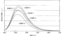
The 1st oxynitride fluorescent material containing Ba, Si and Eu has an emission spectrum having an emission peak in a region from blue green to green, and has extremely high luminous efficiency and excellent temperature characteristics.
In this case, the content of the activator R is preferably 1: 0.005 to 1: 0.15 in terms of a molar ratio of the group II element to the group II element in order to achieve higher luminance, and even in this composition, the light emission efficiency can be maximally improved.
In the 1 st oxynitride phosphor, O and N are contained in the composition, and the weight ratio of O to N is set so that N is in the range of 0.2 to 2.1 relative to 1 of O, whereby a phosphor that is excited with high efficiency by light from an excitation light source and emits light in a region from blue-green to yellow can be obtained.
The 2 nd oxynitride phosphor of the present invention is characterized by having a general formula LXMYOZN((2/3)X+(4/3)Y-(2/3)Z)R or LXMYQTOZN((2/3)X+(4/3)Y+T-(2/3)Z)R represents (L is at least 1 or more group II elements selected from the group consisting of Be, Mg, Ca, Sr, Ba and Zn, M is at least 1 or more group IV elements selected from the group consisting of C, Si, Ge, Sn, Ti, Zr and Hf, Q is at least 1 or more group III elements selected from the group consisting of B, Al, Ga and In, O is an oxygen element, N is a nitrogen element, R is a rare earth element, 0.5<X<1.5, 1.5<Y<2.5, 0<T<0.5, 1.5<Z<2.5).
The 2 nd oxynitride fluorescent material of the present invention thus constituted contains crystals in which elements are arranged in a certain order at least in part, and can emit light from the crystals with high efficiency and has excellent light emission characteristics. Further, since the 2 nd oxynitride phosphor has a light emitting portion which is not a glass body (amorphous type) but a crystal, stable characteristics can be reproduced, and the production and processing thereof are easy. In the above general formula, by setting X, Y and Z to fall within the above ranges, a crystal phase to be a light-emitting part can be formed relatively easily, and a phosphor having good light-emitting efficiency can be provided.
The 2 nd oxynitride fluorescent material of the present invention is excited by light in a short wavelength region from near ultraviolet to visible light, and has an emission spectrum having an emission peak in a blue-green to yellow region. The 2 nd oxynitride phosphor has stability equal to or higher than that of the YAG phosphor.
Here, the 2 nd oxynitride phosphor of the present invention may be deficient in nitrogen, and the general formula in this case is represented by LXMYOZN((2/3)X+(4/3)Y-(2/3)Z-α)R or LXMYQTOZN((2/3)X+(4/3)Y+T-(2/3)Z-α)R (0. ltoreq. α<1) and, in addition, α is closer to zero, the better the crystallinity of the crystal phase is, and the light-emitting luminance can be improved.
In the 2 nd oxynitride phosphor of the present invention, it is preferable that L is at least 1 or more group II elements essential for Ba selected from the group consisting of Ca, Sr, Ba and Zn, M is at least 1 or more group IV elements essential for Si selected from the group consisting of C, Si, Ge, Sn, Ti, Zr and Hf, and Eu is contained as an activator R, in order to achieve higher luminance.
Thus, the 2 nd oxynitride phosphor containing Ba, Si and Eu has an emission spectrum having an emission peak in a region from blue green to green.
Preferably, X, Y and Z are X ═ 1, Y ═ 2 and Z ═ 2. In this composition, more crystal phases can be formed, and the crystallinity thereof can be improved, thereby improving the light emission efficiency.
Thus, the 2 nd oxynitride phosphor of the present invention has at least a part of crystals (crystal phase), and the crystals are contained in an amount of preferably 50 wt% or more, more preferably 80 wt% or more. That is, the crystal phase is a main light-emitting portion, and if the ratio of the light-emitting portion, that is, the crystal phase is 50% by weight or more, high-efficiency light emission can be obtained. Thus, the more the crystal phase, the higher the light emission luminance can be made. Further, if the ratio of the crystal phase is large, the production and processing are easy.
As a result of structural analysis of the X-ray diffraction pattern of the phosphor, the crystals in the 1 st and 2 nd oxynitrides of the present invention have orthorhombic unit lattices and belong to the orthorhombic system.
The rare earth element expressed by R is preferably Eu in order to obtain high luminous efficiency, and in the case of Eu and other rare earth elements, Eu is preferably at least 50% by weight, and Eu is more preferably at least 70% by weight, of R in order to obtain high luminous efficiency.
The 1 st and 2 nd oxynitride phosphors of the present invention are excited by light of an excitation light source having an emission peak wavelength of 490nm or less, and have an emission spectrum having an emission peak wavelength on a longer wavelength side than the emission peak wavelength. That is, the 1 st and 2 nd oxynitride phosphors are excited by a light source having an emission peak wavelength of 490nm or less, and can emit light with high efficiency. The excitation light source for exciting the 1 st and 2 nd oxynitride phosphors of the present invention preferably has a light emission peak wavelength in the range of 240 to 470nm, and more preferably in the range of 350 to 410 nm.
The 1 st and 2 nd oxynitride phosphors can be efficiently excited by light of an excitation light source having an emission peak wavelength at 350nm or more, and further at 360nm or more.
In addition, when the 1 st and 2 nd oxynitrides contain Ba, Si, and Eu, the oxynitride can be efficiently excited by light from an excitation light source having an emission peak wavelength at 360nm to 480nm, and can efficiently emit emission spectrum light having an emission peak wavelength on a longer wavelength side than the emission peak wavelength.
That is, when the oxynitride phosphor contains Ba, Si, and Eu, an excitation light source having an emission peak wavelength at 240 to 480nm can be used as the excitation light source, but an excitation light source having an emission peak wavelength at 360 to 480nm is preferably used. Particularly, an excitation light source of 380 to 420nm or 450 to 470nm used for a semiconductor light emitting element is preferably used.
As described above, the emission spectra of the oxynitride fluorescent materials 1 and 2 of the present invention can be set in the region from blue-green to yellow-red. In addition, in the YAG phosphor having an emission peak wavelength in the yellow wavelength region, although almost no light is emitted even when excitation light in a short wavelength region from near ultraviolet to visible light (for example, excitation light having a wavelength of about 400nm) is used, the 1 st and 2 nd oxynitride phosphors of the present invention exhibit high emission efficiency from the excitation light in this region. In addition, even when the excitation light source uses blue light, high luminous efficiency is exhibited.
In the present specification, the region from cyan to yellowish red is expressed in accordance with JIS Z8110. Specifically, the range from blue-green to yellow-red is 485-610 nm.
The 1 st and 2 nd oxynitride phosphors may have an excitation spectrum in which the emission intensity of light having a wavelength of 370nm is higher than the emission intensity of light having a wavelength of 500 nm. With this arrangement, the phosphor excited by the light in the ultraviolet region has a higher luminance than the phosphor excited by the light in the blue region. When a light-emitting element in the ultraviolet region is used, a light-emitting device having high luminous efficiency can be formed, as compared with a light-emitting element in the blue region.
When the 1 st and 2 nd oxynitride phosphors contain Ba, Si, and Eu, the excitation spectrum can be made higher in intensity in the vicinity of 460nm than in the vicinity of 350 nm. Therefore, a light-emitting device can be formed by using an excitation light source of around 460nm as compared with that of around 350nm, and thus, a high light-emitting efficiency can be exhibited.
The 1 st and 2 nd oxynitride phosphors preferably have at least 2 or more group II elements selected from the group consisting of Be, Mg, Ca, Sr, Ba, and Zn, and thereby can change emission characteristics such as color tone, emission luminance, and quantum efficiency, and can realize desired emission characteristics.
When the 1 st and 2 nd oxynitride phosphors contain Sr and Ca, the molar ratio of Sr to Ca is preferably 6: 4 to 9: 1. When the oxynitride phosphor contains Sr and Ba, the molar ratio of Sr to Ba is preferably 6: 4 to 9: 1. When the 1 st and 2 nd oxynitride phosphors contain Ca and Ba, the molar ratio of Ca to Ba is preferably 6: 4 to 9: 1. By selecting the combination and selecting the composition within the above range, it is possible to produce oxynitride phosphors having various color tones. Further, by selecting this range, the light emission efficiency can be improved.
In the 1 st and 2 nd oxynitride phosphors of the present invention, the emission peak wavelength and the color tone can be set according to the amount of the activator R added.
That is, the oxynitride phosphors 1 and 2 according to the present invention can shift the emission peak wavelength to the short wavelength side or the long wavelength side and can adjust the color tone by controlling the amount of the activator R added.
In the case where the emission peak wavelength and the color tone are changed by the addition amount of the activator R, since a part of the group II element contained in the oxynitride fluorescent material is substituted by the activator R, the amount of the activator R is preferably adjusted in a molar ratio of (the amount of the group II element mixed with the activator R): (the amount of the activator R): 1: 0.001 to 1: 0.8, relative to the amount of the group II element mixed with the activator R. By selecting this range, the color tone can be changed while maintaining high light emission luminance. When Sr is used as the group II element, particularly when the oxynitride phosphor of the present invention is irradiated with an excitation light source of about 400nm, the amount of the activator R to be added is preferably 1: 0.01 to 1: 0.2 (the amount of the group II element mixed with the activator R). When the oxynitride fluorescent material of the present invention is irradiated with an excitation light source of around 460nm, the amount of the activator R to be added is preferably 1: 0.02 to 1: 0.26 (the amount of the group II element mixed with the activator R): (the amount of the activator R). When Ca is used as the group II element, particularly when the oxynitride fluorescent material of the present invention is irradiated with an excitation light source of about 400nm, the amount of the activator R to be added is preferably 1: 0.01 to 1: 0.5 (the amount of the group II element mixed with the activator R): (the amount of the activator R). When the oxynitride fluorescent material of the present invention is irradiated with an excitation light source of around 460nm, the addition amount of the activator R is preferably 1: 0.01 to 1: 0.7 (the mixing amount of the group II element and the activator R): (the amount of the activator R). This is because by selecting this range, an oxynitride phosphor having high luminous efficiency can be provided. Further, in the chromaticity coordinates, by increasing the content of the activator R, the hue x is shifted to the right direction and the hue y is shifted to the downward direction. Thereby enabling the color tone to be changed.
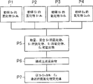
The method for producing an oxynitride phosphor of the present invention includes: a 1 st step of mixing raw materials containing a nitride of L (L is at least 1 or more of II element selected from the group consisting of Be, Mg, Ca, Sr, Ba and Zn), a nitride of M (M is at least 1 or more of IV group element selected from the group consisting of C, Si, Ge, Sn, Ti, Zr and Hf), an oxide of M and an oxide of R (R is a rare earth element); and a 2 nd step of firing the mixture obtained in the 1 st step.
According to the method for producing an oxynitride phosphor of the present invention, a phosphor which is easy to produce and process can be provided. In addition, a phosphor having extremely good stability can be provided. Here, the oxynitride phosphor precursor produced by the production process of the present production method or the present production method may contain Li, Na, K, Rb, Cs, Mn, Re, Cu, Ag, Au, and the like. However, the above Li, Na, K and the like are preferably 1000ppm or less based on the weight of the oxynitride fluorescent material. More preferably 100ppm or less. Since if the amount is in this range, high luminous efficiency can be maintained. Further, an appropriate amount of Li, Na, K,or the like can increase the particle diameter, increase the emission luminance, or the like, and can adjust the emission characteristics, or can improve the characteristics in some cases. These Li, Na, K and the like may be contained in the raw material composition. Since Li, Na, K, and the like are scattered in the firing step in the oxynitride phosphor production process, they are hardly contained in the composition. In addition, other elements may be added within a range not impairing the characteristics.
In the present manufacturing method, it is preferable to use a nitride of R instead of or together with the oxide of R. Thereby, an oxynitride phosphor having high emission luminance can be provided.
In the step 1, Q (Q is at least 1 or more group III elements selected from the group consisting of B, Al, Ga, and In) is preferably further mixed. This increases the particle size and improves the emission luminance.
In the method for producing an oxynitride phosphor of the present invention, the nitride of L, the nitride of M, and the oxide of M are preferably adjusted to a molar ratio of 0.5<nitride of L<1.5, 0.25<nitride of M<1.75, and 2.25<oxide of M<3.75. Thereby, the composition L can be providedXMYOZN((2/3)X+(4/3)Y-(2/3)Z)R or LXMYQTOZN((2/3)X+(4/3)Y+T-(2/3)Z)R is an oxynitride phosphor.
At least a part of the raw material composed of the L nitride is preferably substituted with at least one of an oxide of R or a nitride of R. Thereby, an oxynitride phosphor having high luminous efficiency can be provided.
The 3 rd oxynitride phosphor of the present invention is an oxynitride phosphor produced by the above-described method for producing an oxynitride phosphor.
As described above, the 1 st to 3 rd oxynitride phosphors of the present invention have the technical significance of: a phosphor which is excited by light in a short wavelength region from near ultraviolet to visible light and emits light in a region from blue green to yellow, and a light-emitting device which is excellent in light emission efficiency by combination with an appropriate excitation light source can be provided.
That is, the YAG phosphor having an emission peak wavelength in the yellow color hardly emits light even when excited light of ultraviolet or near ultraviolet is used, but the oxynitride phosphor of the present invention emits light from excited light in a short wavelength region from ultraviolet to visible light and exhibits high emission efficiency.
The short wavelength region from ultraviolet to visible light is not particularly limited, but is a region of 240 to 500nm or less. Particularly, the particle size is preferably in the range of 290 to 470 nm. More preferably 340 to 410 nm.
Further, according to the present invention, a crystalline oxynitride phosphor which is easy to manufacture and process can be provided. Further, an oxynitride phosphor having excellent stability and reproducibility can be provided. Further, a method for producing a novel oxynitride phosphor can be provided.
Further, the oxynitride fluorescent material containing Ba, Si and Eu of the present invention can provide a fluorescent material which can be excited by light in a short wavelength region from ultraviolet to visible light and has excellent luminous efficiency in emitting light in a region from blue green to green.
A 1 st light-emitting device according to the present invention is a light-emitting device including an excitation light source and a phosphor that converts at least a part of a wavelength of light from the excitation light source, the light-emitting device including: the phosphor contains an oxynitride phosphor having an emission peak wavelength in a region from blue green to yellow red. According to the 1 st light-emitting device, a light-emitting device with high light-emitting efficiency can be provided.
A 2 nd light-emitting device according to the present invention is a light-emitting device including an excitation light source having an emission wavelength in a short wavelength region from ultraviolet to visible light, and a phosphor which absorbs at least a part of light from the excitation light source, performs wavelength conversion, and has an emission color different from an emission color of the excitation light source, the light-emitting device including: the phosphor contains an oxynitride phosphor required to have Ba having an emission wavelength in a region from blue green to green. Thus, a light-emitting device having high light-emitting efficiency and excellent color rendering properties can be provided. Further, it is possible to provide a light-emitting device in which part of light from an excitation light source having an emission wavelength in a short wavelength region from ultraviolet to visible light and part of light from an oxynitride fluorescent material having an emission peak wavelength in a region from blue green to green are mixed light, and light is emitted in a region from blue violet to green.
In the 1 st and 2 nd light emitting devices of the present invention, the oxynitride phosphor is preferably 1 of the 1 st to 3 rd oxynitride phosphors of the present invention.
Further, by using the 1 st to 3 rd oxynitride phosphors in which the emission peak wavelength and the color tone are adjusted by the addition amount of the activator R, it is possible to provide a light-emitting device having a desired color tone with different emission peak wavelengths and color tones.
In the 1 st and 2 nd light emitting devices, the 1 st to 3 rd oxynitride phosphors are excited by an excitation light source in a short wavelength region from ultraviolet or near ultraviolet to visible light, and absorb part of light of the excitation light source. The oxynitride fluorescent material excited by the absorption of the light performs wavelength conversion (emits light having a wavelength different from that of the absorbed light). The wavelength-converted light has a light emission peak wavelength in a region from blue green to yellow. That is, the 1 st to 3 rd oxynitride phosphors absorb a part of light from the light emitting element and emit light having an emission spectrum having an emission peak wavelength in a region from blue green to yellow. Further, the 1 st to 3 rd oxynitride phosphors have high light emission efficiency, and can wavelength-convert light from the light emitting element with extremely high efficiency and emit light. Further, by mixing the light from the light-emitting element and the light from the 1 st to 3 rd oxynitride phosphors, a light-emitting device having an intermediate color between the emission color of the light-emitting element and the emission color of the oxynitride phosphor can be provided.
The 1 st to 3 rd oxynitride fluorescent materials can be efficiently excited by a light emitting element such as a near ultraviolet light when they contain O and N, and the weight ratio of O to N is 0.2 to 2.1 relative to 1 of O.
The excitation light source preferably has at least 1 emission peak wavelength in a short wavelength side region from ultraviolet to visible light. The reason is that the luminous efficiency of the phosphor can be improved by using the excitation light source in this range. In particular, it is preferable to use an excitation light source having a luminescence peak wavelength at 240 to 470nm, and more preferable to use an excitation light source having a luminescence peak wavelength at 350 to 410 nm.
The excitation light source is preferably a light emitting element. That is, the light emitting element is small in size, has high power efficiency, and emits bright color light. In addition, since the light emitting element is a semiconductor element, there is no fear of filament breakage or the like of the bulb. Further, the liquid crystal display device is excellent in initial driving characteristics, and is vibration-resistant and resistant to repeated on/off lighting. For this reason, in the present invention, a combination of a light-emitting element and an oxynitride phosphor is preferable.
The light-emitting layer of the light-emitting element preferably has a nitride semiconductor containing In. The light emitting element emits light having an emission peak wavelength in the vicinity of 350 to 410nm, and the oxynitride fluorescent material is excited with high efficiency by the light from the light emitting element, thereby exhibiting a predetermined emission color. The oxynitride fluorescent material is excited by light in the vicinity of 350 to 410nm to obtain high-intensity light emission, and therefore, a light-emitting element in the wavelength region is suitably used. In addition, since the light-emitting element can narrow the width of the emission spectrum, the oxynitride fluorescent material can be efficiently excited, and light substantially free from a change in color tone can be emitted from the light-emitting device.
In the 1 st and 2 nd light emitting devices of the present invention, the 2 nd phosphor may be contained together with the oxynitride phosphor as the phosphor. In the present invention, the 2 nd phosphor preferably converts at least a part of the light from the excitation light source and the light from the oxynitride phosphor in wavelength, and has an emission peak wavelength in a visible light region. Thus, a light-emittingdevice having a light-emitting color in the visible light region can be provided by mixing the light from the excitation light source, the light from the oxynitride fluorescent material, and the light from the 2 nd fluorescent material. The light-emitting device thus configured can emit a desired luminescent color in a wavelength region from the luminescent color of the excitation light source to the luminescent color of the oxynitride phosphor or the luminescent color of the 2 nd phosphor.
The 2 nd phosphor may have at least 1 or more emission peak wavelengths in a range from a blue region to green, yellow, and red regions in order to realize a desired emission color (as an emission color of a light-emitting device). In particular, by combining the three primary colors of green, blue and red of the No. 2 phosphor of the oxynitride phosphor excited by an excitation light source having an emission peak wavelength in a short wavelength region from ultraviolet to visible light, various emission colors can be realized. Further, a light-emitting device in which 2 colors such as green and red, green and yellow, and the like are combined may be used.
The above-mentioned 2 nd phosphor is preferably at least 1 or more selected from alkaline earth halogen apatite phosphors activated mainly by a lanthanide such as Eu or a transition metal-based element such as Mn, alkaline earth metal borate halogen phosphors, alkaline earth metal aluminate phosphors, alkaline earth silicates, alkaline earth sulfides, alkaline earth thiogallates, alkaline earth silicon nitrides, germanates, rare earth aluminates or rare earth silicates activated mainly by a lanthanide such as Ce, or organic and organic complexes activated mainly by a lanthanide such as Eu. Thus, a light-emitting device having high emission efficiency such as emission luminance and quantum efficiency can be provided. Further, a light-emitting device with good color rendering properties can be provided. However, the 2 nd phosphor is not limited thereto, and phosphors emitting light in various hues can be used.
In the light-emitting device including the 2 nd phosphor, it is preferable that at least 2 or more kinds of light among a part of light from the excitation light source, a part of light from the oxynitride phosphor, light from the 2 nd phosphor, and the like are mixed and emitted. This enables the light-emitting device to adjust the emission color thereof and to emit a desired emission color. In particular, in the case of using a light emitting element that emits light in the ultraviolet region, the light emission color in the ultraviolet region is hardly visible to the human eye. Therefore, the emission color formed by mixing the light from the oxynitride phosphor and the light from the 2 nd phosphor is displayed. Since the emission color is determined only by the phosphor, the emission color can be adjusted very easily. Here, the 2 nd phosphor is shown, but the 2 nd phosphor is not limited to 1 kind, and may contain a plurality of kinds of phosphors. By containing a plurality of kinds of phosphors, more subtle chromaticity adjustment can be performed. In particular, in the case of a light-emitting element using a short wavelength region of ultraviolet light or visible light, since light emitted from the light-emitting element rarely gives a color sensation to human eyes, it is possible to reduce variations in chromaticity due to manufacturing variations.
The emission color of the light-emitting device including the 2 nd phosphor can be set to a color from the emission peak wavelength of the excitation light source to the emission peak wavelength of the oxynitride phosphor or the emission peak wavelength of the 2 nd phosphor. The excitation light source has an emission spectrum on a shorter wavelength side than the oxynitride phosphor or the 2 nd phosphor, and has a high energy. The light-emitting devicecontaining the 2 nd phosphor can emit light in a color ranging from the high energy region to the low energy regions of the oxynitride phosphor and the 2 nd phosphor. In particular, the emission color is shown from the emission peak wavelength of the light emitting element to the 1 st emission peak wavelength of the oxynitride or the 2 nd emission peak wavelength possessed by the 2 nd phosphor. For example, when the emission peak wavelength of the light emitting element is in the blue region, the emission peak wavelength of the excited oxynitride fluorescent material is in the green region, and the emission peak wavelength of the excited 2 nd fluorescent material is in the red region, a white emission color can be developed by mixing 3 colors. As a different example, when the emission peak wavelength of the light emitting element is in the ultraviolet region, the emission peak wavelength of the excited oxynitride fluorescent material is in the green region, and the emission peak wavelength of the excited 2 nd fluorescent material is in the yellow and red regions, it is possible to realize a yellowish white or multicolor emission color. By changing the amounts of the oxynitride phosphor and the 2 nd phosphor, a light emission color ranging from a color tone close to the light emission color of the oxynitride phosphor to a color tone close to the light emission color of the 2 nd phosphor can be realized. Further, when the 2 nd phosphor has an emission peak wavelength of 2 or more, a light emitting device that displays an emission color between an emission peak wavelength of the excitation light source, an emission peak wavelength of the oxynitride phosphor, and an emission peak wavelength of 2 or more of the 2 nd phosphor can be realized. The 2 nd phosphor may be used not only in 1 kind but also in combination of 2 or more kinds. Recently, not only a light-emitting device emitting white light but also a light-emitting device emitting light of various hues such as light tint has been required. According to the light-emitting device of the present invention, a light-emitting device having a desired color tone can be provided by combining an oxynitride phosphor that emits green light, a phosphor that emits red light, and a phosphor that emits blue light. In the light emitting device of the present invention, not only the method of changing the kind of the phosphor, but also a method of changing the mixing ratio of the combined phosphors, a method of changing the coating method of coating the phosphor on the excitation light source, a method of adjusting the light emission time of the excitation light source, and the like can be used to realize various color tones.
When a white system is selected as the intermediate emission color, a white color near the locus of black body emission is particularly preferable. Such a white light-emitting device can be used for various purposes such as illumination, a backlight of a liquid crystal, and a display.
The light-emitting device preferably has an emission spectrum having at least 1 emission peak wavelength at 430 to 500nm and 500 to 730 nm. By combining blue light, green light, red light, and the like, a light-emitting device that emits desired color dimming can be provided. Therefore, by combining several phosphors, the color rendering property can be improved. Even if the light emission is of the same white color, the light emission is both yellowish white and bluish white. Therefore, the light-emitting spectrum has a light-emitting peak wavelength in the above range.
As described above, the light-emitting device of the present invention has a technical significance in providing an excellent light-emitting device using an oxynitride fluorescent material that is excited by a light-emitting element in the ultraviolet to visible light region to convert the wavelength. The oxynitride phosphor has high luminous efficiency, is stable, and has high reproducibility. Further, it is technically significant to provide a light-emitting device having a desired emission color by combining a light-emitting element, an oxynitride phosphor, and a 2 nd phosphor.
In the present specification, the relationship between the wavelength range of light and the color name of monochromatic light is defined in accordance with JIS Z8110. Specifically, 380-455 nm is bluish purple, 455-485 nm is blue, 485-495 nm is cyan, 495-548 nm is green, 548-573 nm is yellow green, 573-584 nm is yellow, 584-610 nm is yellow red, and 610-780 nm is red.
In addition, the 2 nd light emitting device of the present invention is preferably a light emitting device having an emission spectrum with at least 1 or more emission peak wavelengths at 360 to 485nm, 485 to 548nm, and 548 to 730 nm. By combining three primary colors of blue, green, red, and the like, a light-emitting device that emits light of a desired color tone can be provided. Further, by combining several kinds of phosphors, color rendering properties can be improved. This is because the white light is both yellowish and bluish even if the white light is emitted.
The 2 nd light-emitting device preferably has a light-emitting spectrum having a light-emitting peak wavelength of 1 or more at 360 to 485nm and 485 to 548 nm. For example, a light-emitting device that emits white light can be obtained by combining a blue light-emitting element and a YAG phosphor, but light near 500nm is insufficient. Therefore, by further including an oxynitride phosphor that emits light in the vicinity of 500nm in the light-emitting device, a light-emitting device with excellent color rendering properties can be provided.
The 2 nd light-emitting device preferably has an average color development evaluation index (Ra) of 80 or more. This makes it possible to provide a light-emitting device having excellent color rendering properties. In particular, a light-emitting device with improved special color rendering properties (R9) can be provided.
As described above, according to the 1 st and 2 nd light emitting devices of the present invention, vivid light emission colors can be realized. In particular, the oxynitride fluorescent material emits light in a region from blue-green to yellow by light from the light emitting element having ultraviolet light. Further, by changing the composition ratio of the oxynitride phosphor, a light-emitting device having excellent light-emitting characteristics can be provided. Further, a light-emitting device having high light-emitting efficiency and excellent reproducibility can be provided. In addition, by changing the blend ratio of the activator R (particularly Eu), the color tone can be changed. Further, by changing the mixing ratio of Eu, an oxynitride phosphor having excellent emission luminance and quantum efficiency can be provided. Therefore, the present invention has an extremely important technical significance in providing such a light-emitting device.
In addition, according to the 2 nd light emitting device of the present invention, for example, a light emitting device which emits light from vivid blue to green can be provided. Further, a light-emitting device in which the oxynitride phosphor, the YAG phosphor as the 2 nd phosphor, and the blue light-emitting element are combined can be manufactured. This makes it possible to provide a light-emitting device which has excellent color rendering properties and which emits white light and has extremely high light-emitting efficiency. This color rendering property can improve the special color rendering evaluation index (R9) for displaying red color in particular.
Drawings
Fig. 1 is a diagram showing a projectile-type light emitting device 1 according to embodiment 2 of the present invention.
Fig. 2A is a plan view showing a surface-mount light-emitting device according to embodiment 3 of the present invention.
Fig. 2B is a sectional view showing a surface-mount light-emitting device according to embodiment 3 of the present invention.
Fig. 3 is a graph showing an emission spectrum when the oxynitride phosphors of examples 1 to 5 were excited at Ex ═ 400 nm.
Fig. 4 is a graph showing an emission spectrum when the oxynitride phosphors of examples 1 to 5 were excited at Ex-460 nm.
FIG. 5 is a graph showing the excitation spectra of the oxynitride phosphors of examples 1 to 5.
FIG. 6 is a graph showing the reflection spectrum of the oxynitride phosphors of examples 1 to 5.
Fig. 7 is an SEM photograph of the oxynitride phosphor of example 1.
Fig. 8 is a graph showing emission spectra when the oxynitride phosphors of examples 6 to 10 were excited at Ex ═ 400 nm.
Fig. 9 is a graph showing emission spectra when the oxynitride phosphors of examples 6 to 10 were excited at Ex-460 nm.
Fig. 10 is a graph showing an emission spectrum when the oxynitride phosphors of examples 11 to 15 were excited at Ex ═ 400 nm.
FIG. 11 is a graph showing the emission spectra when the oxynitride phosphors of examples 11 to 15 were excited at Ex of 460 nm.
FIG. 12 is a graph showing the excitation spectra of the oxynitride phosphors of examples 11 to 15.
FIG. 13 is a graph showing the reflection spectra of the oxynitride phosphors of examples 11 to 15.
Fig. 14 is a graph showing emission spectra when the oxynitride phosphors of examples 10 and 16 to 20 were excited at Ex ═ 400 nm.
Fig. 15 is a graph showing an emission spectrum when the oxynitride phosphors of examples 10 and 16 to 20 were excited at Ex 460 nm.
FIG. 16 is a graph showing the excitation spectra of the oxynitride phosphors of examples 10, 16 to 20.
FIG. 17 is a graph showing the reflection spectra of the oxynitride phosphors of examples 10, 16 to 20.
FIG. 18 is a graph showing the emission spectra when the oxynitride phosphors of examples 21 to 24 were excited at Ex of 400 nm.
FIG. 19 is a graph showing the emission spectra when the oxynitride phosphors of examples 21 to 24 were excited at Ex of 460 nm.
FIG. 20 is a graph showing excitation spectra of oxynitride phosphors of examples 21 to 24.
FIG. 21 is a graph showing the reflection spectra of the oxynitride phosphors of examples 21 to 24.
FIG. 22 is a schematic view showing an orthorhombic system.
FIG. 23 is a diagram showing an X-ray diffraction pattern of an oxynitride fluorescent material of example 25.
FIG. 24 is a diagram showing an X-ray diffraction pattern of an oxynitride fluorescent material of example 26.
FIG. 25 is a graph showing an X-ray diffraction pattern of an oxynitride fluorescent material of example 27.
Fig. 26 is a plan view showing a light-emitting element of the present invention.
Fig. 27 is a sectional view a-a' showing a light-emitting element of the present invention.
Fig. 28 is a diagram showing an emission spectrum of a light-emitting device according to example 28 of the present invention.
Fig. 29 is a diagram showing chromaticity coordinates of a light-emitting device according to example 28 of the present invention.
Fig. 30 is a view showing a light-emitting device according to a cap-type example 30 of the present invention.
Fig. 31 is a process diagram showing a method for producing an oxynitride phosphor.
Fig. 32 is a graph showing changes in luminous efficiency when the content of the activator R contained in the composition of the oxynitride phosphor is changed.
Fig. 33 is a graph showing changes in luminous efficiency when the content of the activator R contained in the composition of the oxynitride phosphor was changed.
Fig. 34 is a CIE chromaticity diagram showing changes in color tone when the content of the activator R contained in the composition of the oxynitride fluorescent material is changed.
Fig. 35 is an enlarged CIE chromaticity diagram of fig. 34.
Fig. 36 is a graph showing an emission spectrum when an oxynitride fluorescent material is excited at Ex ═ 400 nm.
Fig. 37 is a graph showing an emission spectrum when an oxynitride phosphor is excited at Ex-460 nm.
Fig. 38 is a diagram showing a normalized excitation spectrum of an oxynitride phosphor.
Fig. 39 is a graph showing a reflection spectrum of an oxynitride phosphor.
Fig. 40A is an SEM photograph at 1000 × magnification of the oxynitride phosphor of example 36, fig. 40B is an SEM photograph at 5000 × magnification of the oxynitride phosphor of example 36, and fig. 40C is an SEM photograph at 10000 × magnification of the oxynitride phosphor of example 36.
Fig. 41 is a graph showing changes in luminous efficiency when the content of the activator R contained in the composition of the oxynitride phosphor was changed.
Fig. 42 is a graph showing changes in luminous efficiency when the content of the activator R contained in the composition of the oxynitride phosphor is changed.
Fig. 43 is a CIE chromaticity diagram showing a change in color tone when the content of the activator R contained in the composition of the oxynitride fluorescent material is changed.
Fig. 44 is a CIE chromaticity diagram enlarged by 43.
Fig. 45 is a graph showing an emission spectrum when an oxynitride fluorescent material is excited at Ex ═ 400 nm.
Fig. 46 is a graph showing an emission spectrum when an oxynitride phosphor is excited at Ex-460 nm.
Fig. 47 is a diagram showing a normalized excitation spectrum of an oxynitride phosphor.
Fig. 48 is a graph showing a reflection spectrum of an oxynitride phosphor.
Fig. 49 is a graph showing changes in peak intensity when the content of the activator R contained in the composition of the oxynitride phosphor is changed.
Fig. 50 is a graph showing changes in luminous efficiency when the content of the activator R contained in the composition of the oxynitride phosphor was changed.
Fig. 51 is a graph showing an emission spectrum when an oxynitride fluorescent material is excited at Ex ═ 400 nm.
Fig. 52 is a graph showing an emission spectrum when an oxynitride phosphor is excited at Ex-460 nm.
Fig. 53 is a diagram showing a normalized excitation spectrum of an oxynitride phosphor.
Fig. 54 is a graph showing a reflection spectrum of an oxynitride phosphor.
Fig. 55 is a graph showing an emission spectrum when the oxynitride fluorescent material of example 79 was excited with Ex ═ 400 nm.
Fig. 56 is a graph showing an emission spectrum when the oxynitride fluorescent material of example 79 was excited at Ex-460 nm.
FIG. 57 is a graph showing the normalized excitation spectrum of the oxynitride phosphor of example 79.
FIG. 58 is a graph showing the reflection spectrum of the oxynitride phosphor of example 79.
Fig. 59A is an SEM photograph at 1000 × magnification of the oxynitride phosphor of example 79, and fig. 59B is an SEM photograph at 10000 × magnification of the oxynitride phosphor of example 79.
Fig. 60 is a diagram showing an emission spectrum of the light-emitting device 1 of the present invention.
Fig. 61 is a chromaticity diagram showing chromaticity coordinates of the light emitting device 1 of the present invention.
FIG. 62 is a process diagram showing a method for producing an oxynitride phosphor.
Fig. 63 is a graph showing emission spectra when the oxynitride phosphors of examples 83 to 87 were excited at Ex-400 nm.
Fig. 64 is a graph showing emission spectra when the oxynitride phosphors of examples 83 to 87 were excited at Ex-460 nm.
FIG. 65 is a graph showing the excitation spectra of the oxynitride phosphors of examples 83 to 87.
FIG. 66 is a graph showing the reflection spectra of the oxynitride phosphors of examples 83 to 87.
Fig. 67A and 67B are SEM photographs of the oxynitride phosphor of example 83.
Fig. 68 is a diagram showing an emission spectrum (simulation) of a light-emitting device of example 88.
FIG. 69 is a graph showing light emission spectra (simulation) of light-emitting devices of examples 88 to 90;
fig. 70 is a graph showing the emission spectra (simulation) of the light-emitting devices of examples 89 and 90.
Fig. 71 is a diagram showing the emission spectra of the light-emitting devices of examples 91 and 92.
Detailed Description
Hereinafter, a light-emitting device, an oxynitride phosphor used in the light-emitting device, and a method for producing the oxynitride phosphor will be described with reference to embodiments and examples. However, the present invention is not limited to the embodiment and the examples.
Embodiment mode 1
Embodiment 1 relates to an oxynitride phosphor which is suitably used in combination with a light emitting element, particularly a nitride semiconductor element, and which is excited by light of the nitride semiconductor light emitting element to generate light having a wavelength different from that of the light emitting element.
The oxynitride phosphor according to embodiment 1 is a phosphor using a rare earth element as an activator and containing an oxynitride phosphor crystal containing at least 1 or more group II elements selected from the group consisting of Be, Mg, Ca, Sr, Ba, and Zn and at least 1 or more group IV elements selected from the group consisting of C, Si, Ge, Sn, Ti, Zr, and Hf.
The oxynitride phosphor crystal is, for example, an oxynitride phosphor composed of a crystal belonging to an orthorhombic crystal shown in examples described later.
The combination of the group II element and the group IV element is arbitrary, but the following combination is preferably used.
The oxynitride fluorescent material of preferred embodiment 1 has a general formula LXMYOZN((2/3)X+(4/3)Y-(2/3)ZR or LXMYQTOZN((2/3)X+(4/3)Y+T-(2/3)Z)R represents. Here, L is a group consisting of,At least 1 or more group II elements selected from the group consisting of Mg, Ca, Sr, Ba and Zn. M isAt least 1 or more group IV elements selected from the group consisting of C, Si, Ge, Sn, Ti, Zr and Hf. Q is at least 1 or more group III elements selected from the group consisting of B, Al, Ga and In. O is oxygen element. N is nitrogen element. R is rare earth element. X is more than 0.5 and less than 1.5, Y is more than 1.5 and less than 2.5, T is more than 0 and less than 0.5, and Z is more than 1.5 and less than 2.5.
The oxynitride fluorescent material represented by the general formula can contain crystals in which at least a part of the elements are regularly arranged, and can efficiently emit light with high luminance from the crystals. In the above general formula, by setting 0.5<X<1.5, 1.5<Y<2.5, 0<T<0.5, and 1.5<Z<2.5, a crystal phase which is a light-emitting part can be formed relatively easily, and a phosphor having excellent light-emitting efficiency and high luminance can be provided.
In the above general formula X, Y, Z, X ═ 1, Y ═ 2, and Z ═ 2 are preferable. In this composition, more crystal phases can be formed, and the crystallinity thereof can be improved, and the luminous efficiency and luminance can be improved. The ratio of the crystal (crystal phase) contained in the oxynitride phosphor according to embodiment 1 is preferably 50 wt% or more, and more preferably 80 wt% or more.
In the case where the ratio of the crystal to be included is set to a desired value for the purpose of adjusting the light emission luminance or the like, the adjustment can be made by using the X, Y, Z value in the above general formula.
However, the above range is a preferable range, and the present invention is not limited to the above range.
Specifically, the oxynitride fluorescent material of the present invention contains CaSi2O2N2:Eu、SrSi2O2N2:Eu、BaSi2O2N2:Eu、ZnSi2O2N2:Eu、CaGe2O2N2:Eu、SrGe2O2N2:Eu、BaGe2O2N2:Eu、ZnGe2O2N2:Eu、Ca0.5Sr0.5Si2O2N2:Eu、Ca0.5Ba0.5Si2O2N2:Eu、Ca0.5Zn0.5Si2O2N2:Eu、Ca0.5Be0.5Si2O2N2:Eu、Sr0.5Ba0.5Si2O2N2:Eu、Ca0.8Mg0.2Si2O2N2:Eu、Sr0.8Mg0.2Si2O2N2:Eu、Ca0.5Mg0.5Si2O2N2:Eu、Sr0.5Mg0.5Si2O2N2:Eu、CaSi2B0.1O2N2:Eu、SrSi2B0.1O2N2:Eu、BaSi2B0.1O2N2:Eu、ZnSi2B0.1O2N2:Eu、CaGe2B0.01O2N2:Eu、SrGe2G0.01O2N2:Eu、BaGe2In0.01O2N2:Eu、ZnGe2Al0.05O2N2:Eu、Ca0.5Sr0.5Si2B0.3O2N2:Eu、CaSi2.5O1.5N3:Eu、SrSi2.5O1.5N3:Eu、BaSi2.5O1.5N3:Eu、Ca0.5Ba0.5Si2.5O1.5N3:Eu、Ca0.5Sr0.5Si2.5O1.5N3:Eu、Ca1.5Si2.5O2.5N2.7:Eu、Sr1.5Si2.5O2.5N2.7:Eu、Ba1.5Si2.5O2.5N2.7:Eu、Ca1.0Ba0.5Si2.5O1.5N3:Eu、Ca1.0Sr0.5Si2.5O1.5N3:Eu、Ca0.5Si1.5O1.5N1.7:Eu、Sr0.5Si1.5O1.5N1.7:Eu、Ba0.5Si1.5O1.5N1.7:Eu、Ca0.3Ba0.2Si2.5O1.5N3:Eu、Ca0.2Sr0.3Si2.5O1.5N3Eu, etc.
As described herein, the oxynitride fluorescent material according to embodiment 1 can be adjusted in color tone and luminance by changing the ratio of O to N. Further, the molar ratio of the cation to the anion expressed as (L + M)/(O + N) can also be varied, whereby the emission spectrum or intensity can also be adjusted accurately. This can be performed by, for example, performing a treatment such as vacuum, removal of N or O, and the like, but the present invention is not limited to this method. The oxynitride phosphor may contain at least 1 or more of Li, Na, K, Rb, Cs, Mn, Re, Cu, Ag and Au in its composition, and the addition of these components can adjust the light emission efficiency such as luminance and quantum efficiency. In addition, other elements may be added within a range not impairing the characteristics.
A part of the group II element contained in the oxynitride phosphor may be substituted with the activator R. The amount of the activator R is preferably a molar ratio of (the mixed amount of the group II element and the activator R) to (the amount of the activator R) of 1: 0.001 to 1: 0.8 relative to the mixed amount of the group II element and the activator R.
L is at least 1 or more group II elements selected from the group consisting of Be, Mg, Ca, Sr, Ba and Zn. In the present invention, L may be a monomer such as Ca and Sr, but may form a multi-element combination of Ca and Sr, Ca and Ba, Sr and Ba, Ca and Mg, and the like. Further, when L is a multi-element combination, the composition ratio thereof can also be changed. For example, a mixture of Sr and Ca can be mixed in varying proportions as desired.
In particular, L is preferably at least 1 or more group II elements necessary for any 1 of Ca, Sr, or Ba selected from the group consisting of Mg, Ca, Sr, Ba, and Zn.
M is at least 1 or more group IV elements selected from the group consisting of C, Si, Ge, Sn, Ti, Zr and Hf. M may be a single element such as Si or Ge, or may be a combination of Si or Ge and a plurality of elements such as Si or C. In the present invention, the above-mentioned group IV element can be used, but Si and Ge are preferably used. By using Si or Ge, a phosphor having excellent crystallinity can be provided at low cost.
In particular, M is preferably at least 1 or more group IV elements selected from the group consisting of C, Si, Ge, Sn, Ti, and Hf, which are necessary for Si.
R is a rare earth element. Specifically, R is 1 or 2 or more elements selected from La, Ce, Pr, Nd, Sm, Eu, Gd, Tb, Dy, Ho, Er, Tm, Yb and Lu. In the present invention, Eu is preferably used among these rare earth elements. Further, Eu and at least 1 or more elements selected from rare earth elements may be contained. In this case, it is preferable that R contains Eu at 50 wt% or more, and more preferably 70 wt% or more. That is, the activator R is preferably at least 1 or more kinds of rare earth elements selected from the group consisting of La, Ce, Pr, Nd, Sm, Eu, Gd, Tb, Dy, Ho, Er, Tm, Yb and Lu, which are essential for Eu. Elements other than Eu are intended to function as co-activators.
In embodiment 1, a rare earth element europium Eu is used as a luminescence center. Europium has mainly valence 2 and 3 energy levels. The phosphor of embodiment 1 uses Eu as the base alkaline earth metal-based silicon nitride2+As an activator. Eu (Eu)2+Eu, which is easily oxidized, usually in the valence state of 32O3The composition of (1) is sold.
In the present specification, a case where the representative example Eu is used as the emission center will be described in some cases, but the present invention is not limited to this.
As the matrix material, each compound can be used as the main component L, M. L, M as the main component, a metal, an oxide, an imide, an amide, a nitride, and various salts can be used. Further, the elements of L and M as the main components may be mixed in advance and used.
Q is at least 1 or more group III elements selected from the group consisting of B, Al, Ga and In. Q may also be a metal, an oxide, an imide, an amide, a nitride, or various salts. For example, B2O6、H3BO3、Al2O3、Al(NO3)3·9H2O、AlN、GaCl3、InCl3And the like.
A nitride of L, a nitride of M, and an oxide of M are mixed as a host material. An oxide of Eu is mixed as an activator into the base material. These materials were weighed to achieve the desired phosphor composition and mixed until uniform. In particular, the nitride of L, the nitride of M and the oxide of M in the matrix material are preferably mixed in a molar ratio of 0.5<nitride of L<1.5, 0.25<nitride of M<1.75 and 2.25<oxide of M<3.75. I.e. to reach LXMYOZN((2/3)X+Y-(2/3)Z-α)R or LXMYQTOZN((2/3)X+Y+T-(2/3)Z-α)The base materials were weighed in a predetermined amount so as to obtain the composition ratio of R, and mixed.
(method for producing oxynitride phosphor)
Next, the oxynitride phosphor CaSi according to embodiment 1 will be described2O2N2A method for producing Eu. The present invention is not limited to the following manufacturing method.
First, a nitride of Ca, a nitride of Si, an oxide of Si, and an oxide of Eu are prepared. As these raw materials, purified ones are preferably used, but commercially available ones may be used.
Preparation of nitrides of Ca
First, the raw material Ca was pulverized. The raw material Ca is preferably a monomer, but a compound such as imide compound, amide compound, CaO, or the like may be used. The raw material Ca may contain B, Ga or the like. The raw material Ca was pulverized in a ball box under an argon atmosphere. The average particle diameter of Ca obtained by pulverization is preferably about 0.1 to 15 μm, but not limited to this range. The purity of Ca is preferably 2N or more, but is not limited to this range.
Subsequently, the pulverized raw material Ca was nitrided in a nitrogen atmosphere. The nitride of Ca can be obtained by nitriding the pulverized Ca at 600 to 900 ℃ for about 5 hours in a nitrogen atmosphere. The reaction formula is shown in formula 1.
(formula 1)
The Ca nitride is preferably of high purity. As the Ca nitride, commercially available one can be used.
Subsequently, the Ca nitrides were pulverized. The Ca nitrides were pulverized in a ball box under an argon atmosphere or a nitrogen atmosphere.
Preparation of Si nitrides
First, raw material Si is pulverized. The raw material Si of the monomer is preferably used, but nitride compounds, imide compounds, amide compounds and the like, for example, Si can be used3N4、Si(NH2)2、Mg2Si、Ca2Si, SiC and the like. The purity of Si is preferably 3N or more, but B, Ga or the like may be contained. The pulverization of the raw material Si was also carried out in a ball box in an argon atmosphere or a nitrogen atmosphere as in the case of the raw material Ca. The average particle diameter of the Si compound is preferably about 0.1 to 15 μm.
The raw material Si was nitrided in a nitrogen atmosphere. Silicon nitride is obtained by nitriding silicon (Si) at 800 to 1200 ℃ for about 5 hours in a nitrogen atmosphere. The reaction formula is shown in formula 2.
(formula 2)
The silicon nitride used in the present invention is, of course, preferably of high purity. Further, commercially available silicon nitride may be used.
Subsequently, the Si nitride is pulverized.
Preparation of Si oxide
Oxides of Si, i.e. SiO2Commercially available (99.9% silica Dioxide manufactured by Wako pure chemical industries, Ltd., 190-09072) was used.
The raw materials (Ca nitride, Si oxide, and Eu oxide) thus purified or produced are weighed so as to reach a predetermined molar amount.
Then, the weighed raw materials were mixed.
Next, a mixture of Ca nitride, Si oxide and Eu oxide is fired at about 1500 ℃ in an ammonia gas atmosphere. The fired mixture was put into a crucible and fired.
By mixing and firing, CaSi can be obtained2O2N2Eu, or the like. The reaction formula of the fired basic constituent elements is shown in formula 3.
(formula 3)
However, this composition is a typical composition estimated from the blending ratio, and has sufficient characteristics for practical use in the vicinity of the ratio. Further, the composition of the intended phosphor can be changed by changing the blending ratio of each raw material.
For firing, a tube furnace, a small furnace, a high frequency furnace, a metal furnace, or the like can be used. The firing temperature is not particularly limited, but firing is preferably performed at a temperature in the range of 1200 to 1700 ℃, and more preferably at a temperature in the range of 1400 to 1700 ℃. The phosphor is preferably fired using a crucible or a vessel made of Boron Nitride (BN). Alumina (Al) may be used in addition to the boron nitride crucible2O3) Crucible made of material.
The reducing atmosphere may be a nitrogen atmosphere, a nitrogen-hydrogen atmosphere, an ammonia atmosphere, an inert gas atmosphere such as argon, or the like.
By adopting the above production method, a desired oxynitride phosphor can be obtained.
In addition, Ca containing BXSiYBTOZN((2/3)X+Y+T-(2/3)Z-α)An oxynitride phosphor represented by Eu can be produced as follows.
In advance, dry-mixing compound H of B in the oxide of Eu3BO3. Europium oxide is used as the Eu compound, but similarly to the other constituent elements described above,europium oxide, europium nitride, or the like is used. As the raw material Eu, an imide compound, an amide compound, or the like can be used. Europium oxide is preferably of high purity, but commercially available europium oxide can also be used. The compounds for B may be mixed by a dry method, but may be mixed by a wet method.
Compounds H with B3BO3For example, although the method for producing the oxynitride phosphor is described, among the constituent elements other than B, there are Li, K, Na and the like, and compounds thereof, for example, compounds of these are usableLiOH·H2O、Na2CO3、K2CO3、RbCl、CsCl、Mg(NO3)2、CaCl2·6H2O、SrCl2·6H2O、BaCl2·2H2O、TiOSO4·H2O、ZrO(NO3)2、HfCl4、MnO2、ReCl5、Cu(CH3COO)2·H2O、AgNO3、HAuCl4·4H2O、Zn(NO3)2·6H2O、GeO2、Sn(CH3COO)2And the like.
And crushing the mixture of Eu and B. The average particle diameter of the mixture of Eu and B after pulverization is preferably about 0.1 μm to 15 μm.
After the above-mentioned pulverization, the resulting mixture is substantially in contact with the CaSi2O2N2In the same Eu production process, Ca nitride, Si oxide, and B-containing Eu oxide are mixed. After the mixing, the resultant mixture is fired to obtain the intended oxynitride phosphor.
The oxynitride phosphor according to embodiment 1 has stability equal to or higher than that of the YAG phosphor, and further has the following characteristics.
(1) The oxynitride phosphor according to embodiment 1 can set a desired emission color in a relatively wide range from the blue-green region to the yellow-red region by selecting the composition and the composition ratio thereof, and can have a wide range of adjustment of color tone, emission luminance, and quantum efficiency.
For example, by using 2 or more kinds of group II elements and varying the ratio thereof, the color tone, the light emission luminance, and the quantum efficiency can be adjusted.
(2) The YAG phosphor hardly emits light when excited by light in the ultraviolet to short wavelength visible light region, but the oxynitride phosphor according to embodiment 1 can obtain high emission efficiency by excitation by light in the ultraviolet to short wavelength visible light region.
That is, the oxynitride phosphor according to embodiment 1 can provide a phosphor suitable for a combination with a light emitting element in the ultraviolet to short wavelength visible region.
(3) Since the oxynitride fluorescent material is crystalline, it can be easily produced as a powder or a pellet, and the handling and processing thereof are easy.
Fig. 1 is a sectional view showing a configuration of a light-emitting device according to embodiment 2 of the present invention, and the light-emitting device of the present invention includes at least a light-emitting element and a 1 st phosphor that converts at least a part of light from the light-emitting element into wavelength. Here, in particular, in the light-emitting device of embodiment 2, the oxynitride phosphor of embodiment 1 is used as the 1 st phosphor.
In the present specification, the relationship between the color name and the chromaticity coordinate is referred to JIS Z8110.
In the light-emitting device of embodiment 2, the light-emitting element 10 is composed of a sapphire substrate 1, a semiconductor layer 2 formed on the sapphire substrate 1, and a positive and negative electrode formed on the semiconductor layer 2. The light emitting element 10 is bonded in a cup portion (cup) of the lead frame 13a, and positive and negative electrodes thereof are connected to the lead frame 13a and the lead frame 13b by the conductive wire 14, respectively. Further, a coating member 12 containing a phosphor 11 is formed in the cup-shaped portion of the lead frame 13a so as to cover the light emitting element 10. Then, the mold member 15 is formed so as to cover the entire lead frame 13a and the lead frame 13b provided with the light emitting element and the coating member 12 containing the phosphor 11.
In the light-emitting device of embodiment 2, the semiconductor layer 2 of the light-emitting element 10 is composed of a plurality of layers including a light-emitting layer (not shown), and the composition of the light-emitting layer is adjusted so that the emission peak wavelength reaches 500nm or less in the blue region from ultraviolet. Further, positive and negative electrodes 3 are formed on the same plane side of the semiconductor layer 2.
The light-emitting device of embodiment 2 is manufactured as follows.
First, the light emitting element 10 is placed on a die bonder (die bonder), and bonded face up on the lead frame 13a provided with the cup portion. After bonding, the lead frame 13 is moved to a bonding machine, the negative electrode 3 of the light emitting element is wire bonded to the lead frame 13a provided with the cup-shaped portion with gold wires, and the positive electrode 3 is wire bonded to the other lead frame 13 b.
Next, the molding apparatus is moved, and the phosphor 11 and the coating member 12 are injected into the cup-shaped portion of the lead frame 13 by a dispenser of the molding apparatus. In this case, the phosphor 11 and the coating member 12 are uniformly mixed in advance at a desired ratio.
After the coating, the lead frame 13 is immersed in a mold box previously injected into the mold member 15, and then the mold box is removed and the resin is hardened to produce a bullet type light emitting device shown in fig. 1.
Hereinafter, each component of the light emitting device of embodiment 2 will be described in detail
(phosphor 11)
The phosphor 11 includes the oxynitride phosphor of embodiment 1. In addition, a phosphor 11 combining an oxynitride phosphor and a 2 nd phosphor may be used.
(light-emitting element 10)
In embodiment 2, the light-emitting element 10 is preferably a semiconductor light-emitting element having a light-emitting layer capable of emitting light having a wavelength capable of efficiently exciting an oxynitride phosphor. Examples of the material of such a semiconductor light emitting element include various semiconductors such as BN, SiC, ZnSe, GaN, InGaN, InAlGaN, AlGaN, BAlGaN, and BInAlGaN. Among these elements, as impurity elements, too, canSi, Zn, etc. can be contained as the light-emitting center. As a semiconductor material capable of efficiently emitting light in the ultraviolet region or light having a relatively short wavelength in the visible light region that can efficiently excite the phosphor 11 (oxynitride phosphor), nitride semi-semiconductors are more preferably cited, among othersConductor (e.g., nitride semiconductor containing Al or Ga, nitride semiconductor In containing In or GaXAlYGa1-X-YN、0≤X、0≤Y、X+Y≤1)。
Further, as the structure of the semiconductor light emitting element, a homogeneous structure, a heterostructure, or a double heterostructure having MIS junction, PIN junction, pn junction, or the like is preferably cited. Various emission wavelengths can be selected depending on the material of the semiconductor layer or the mixed crystal ratio thereof. Further, the semiconductor active layer can also be formed into a single quantum well structure or a multiple quantum well structure which is a thin film that generates a quantum effect, thereby improving the output.
When the light-emitting element 10 is made of a nitride semiconductor, a substrate made of a material such as sapphire, spinel, SiC, Si, ZnO, GaAs, or GaN is preferably used. In order to form a nitride semiconductor having good crystallinity with large mass productivity, a sapphire substrate is preferably used. A nitride semiconductor can be formed on the sapphire substrate by HVPE, MOCVD, or the like. Specifically, a non-single crystal buffer layer is formed on a sapphire substrate by growing GaN, AlN, GaAlN or the like at a low temperature, and a nitride semiconductor having a pn junction is formed thereon.
A light-emitting element using a nitride semiconductor, having a pn junction, and capable of efficiently emitting light in an ultraviolet region is manufactured, for example, as follows.
First, SiO is formed on the buffer layer in a stripe shape approximately perpendicular to the orientation plane of the sapphire substrate2. Next, on the bar, GaN was grown by an HVPE method, ELOG (epitaxial Over grown GaN). Next, a 1 st contact layer made ofn-type GaN, a 1 st cladding layer made of n-type AlGaN, an active layer having a multi-quantum well structure in which a well layer of InAlGaN and a barrier layer of AlGaN are laminated in multiple layers, a 2 nd cladding layer made of p-type AlGaN, and a 2 nd contact layer made of p-type GaN are sequentially laminated by MOCVD. Thus, a nitride semiconductor light-emitting element having a double heterostructure was produced.
Further, the semiconductor laser element usable in the present invention can also be formed by forming the active layer into a ridge shape and sandwiching it with the guide layer and providing the resonator end face.
In addition, although the nitride semiconductor exhibits n-type conductivity in a state where no impurity is doped, if an n-type nitride semiconductor having a desired carrier concentration is to be formed for the purpose of improving light emission efficiency or the like, Si, Ge, Se, Te, C, or the like is preferably introduced as an n-type dopant. On the other hand, when a p-type nitride semiconductor is formed, it is preferable to dope with p-type dopant impurities, i.e., Zn, Mg, Be, Ca, Sr, Ba, and the like. Further, since the nitride semiconductor is difficult to be p-type by doping only a p-type dopant, it is preferable to lower the resistance by furnace heating, plasma irradiation, or the like after introducing the p-type dopant. Without removing the sapphire substrate, a portion of the 1 st contact layer was exposed by etching from the p-type side to the surface of the 1 st contact layer, and electrodes were formed on the respective contact layers. Then, a light-emitting element made of a nitride semiconductor (for example, a nitride semiconductor light-emitting element having a structure shown in fig. 1) is fabricated by dicing a semiconductor wafer into a chip shape.
In the light-emitting device of embodiment 2, when the fluorescent material 11 is fixed near the surface of the light-emitting element 10, a resin (transparent resin) is preferably used for good mass productivity. In this case, in consideration of both the relationship with the emission wavelength of the phosphor 11 and the prevention of deterioration of the transparent resin, it is preferable to use a light-emitting element 10 having an emission spectrum in the ultraviolet region and having an emission peak wavelength of 360nm to 420nm, or 450nm to 470 nm.
Here, the semiconductor light emitting element 10 used in embodiment 2 is preferably adjusted so as to have an impurity concentration of 1017~1020/cm3The sheet resistance Rn of the n-type contact layer formed in the above manner and the sheet resistance Rp of the translucent p-electrode have a relationship that Rp is not less than Rn. The n-type contact layer is preferably formed to a thickness of 3 to 10 μm, more preferably 4 to 6 μm, and has an estimated sheet resistance Rn of 10 to 15 Ω/□. Therefore, the thickness is preferably set so that the sheet resistance Rp of the translucent p-electrode is 10 to 15 Ω/□ or more. Specifically, the light-transmitting p-electrode may be formed of a thin film having a thickness of 150 μm or less.
In addition, when the transparent p-electrode is formed by using a multilayer film or an alloy containing 1 selected from the group consisting of gold and platinum group elements and at least 1 other element, the stability and reproducibility can be improved by adjusting the sheet resistance of the transparent p-electrode by the content of the gold and platinum group elements contained therein. Since gold or a metal element has a high absorption coefficient in the wavelength region of the semiconductor light-emitting element used in the present invention, the lower the amount of gold or a platinum group element contained in the translucent p-electrode, the better the transmittance. Although the sheet resistance of the conventional semiconductor light-emitting element is related to Rp ≧ Rn, in embodiment 2, since Rp is adjusted to be equal to or greater than Rn, the translucent p-electrode can be formed into a thin film as compared with conventional products, and in this case, the thin film can be easily formed by reducing the content of gold or platinum group elements.
As described above, in the semiconductor light emitting element 10 used in the present invention, it is preferable that Rp.gtoreq.Rn is a relationship between the sheet resistance Rn.gtoreq. □ of the n-contact layer and the sheet resistance Rp.gtoreq. □ of the translucent p-electrode. After the semiconductor light-emitting element 10 is manufactured, it is difficult to measure Rn, and the relationship between Rp and Rn cannot be known substantially, but it is possible to know what relationship is formed between Rp and Rn from the light intensity distribution state at the time of light emission.
When the translucent p-electrode and the n-type contact layer have a relationship of Rp ≧ Rn, if a p-side pedestal electrode having an extended conductive portion is provided in contact with the translucent p-electrode, the external quantum efficiency can be further improved. The shape and direction of the extended conductive portion are not limited, but when the extended conductive portion is located on the weft, the light-shielding area is preferably reduced, but a mesh shape may be formed. The shape may be a curved shape, a lattice shape, a branch shape, or a hook shape, in addition to a straight shape. At this time, since the light shielding effect is increased in proportion to the total area of the p-side submount electrode, it is preferable to design the line width and length of the extended conductive portion so that the light shielding effect does not exceed the light emission increasing effect.
In embodiment 2,as described above, not only the light-emitting element that emits ultraviolet light but also the light-emitting element that emits blue light may be used as the light-emitting element 10. The light-emitting element 10 that emits blue light is also preferably a group III nitride compound light-emitting element. Such a light emitting element 10 has a stacked structure in which, for example, an n-type GaN layer not doped with Si, an n-type contact layer composed of n-type GaN doped with Si, an undoped GaN layer, a light emitting layer having a multiple quantum well structure (a quantum well structure of GaN barrier layer/InGaN well layer), a p-cladding layer composed of p-type GaN doped with Mg, and a p-type contact layer composed of p-type GaN doped with Mg are stacked in this order on a sapphire substrate 1 via a GaN buffer layer. The electrode is formed in the following manner. However, a light-emitting element having a different configuration may be used.
The p-ohmic electrode is formed on substantially the entire surface of the p-type contact layer, and a p-pad (pad) electrode is formed on a part of the p-ohmic electrode.
Further, an n-electrode is formed on a portion of the n-type contact layer exposed by removing the undoped GaN layer from the p-type contact layer by etching.
In addition, although the light-emitting layer having a multiple quantum well structure is used in this embodiment, the present invention is not limited to this, and for example, a single quantum well structure using InGaN may be formed, or GaN doped with Si or Zn may be used.
In addition, the main emission peak wavelength of the light-emitting layer of the light-emitting element 10 can be changed In the range from 420nm to 490nm by changing the In content. The emission peak wavelength is not limited to the above range, and an emission peak wavelength of 360 to 550nm may be used.
(coating Member 12)
The coating member 12 (light transmissive material) is used in a mixture with the phosphor 11 provided in the cup portion of the lead frame 13. As a specific material of the coating member 12, transparent resin, silica gel, glass, inorganic adhesive, and the like, which are excellent in temperature characteristics and weather resistance, such as epoxy resin, urea resin, and silicone resin, can be used. Further, a diffusing agent, barium titanate, titanium oxide, aluminum oxide, or the like may be contained together with the phosphor. Further, a light stabilizer or a coloring agent may be contained.
(lead frame 13)
The lead frame 13 includes a mounting lead (mount lead)13a and an inner lead 13 b.
And mounting leads 13a for arranging the light emitting element 10. The upper portion of the mounting lead 13a is formed in a cup shape, and the light emitting element 10 is bonded in the cup. The inside of the cup-shaped portion is covered with the phosphor 11 and the coating member 12 so as to cover the light emitting element 10. Further, a plurality of light emitting elements 10 may be disposed in the cup portion, and the mounting lead 13a may be used as a common electrode for the plurality of light emitting elements 10. In this case, sufficient conductivity and connectivity with the conductive wire 14 are required. The bonding (adhesion) of the light-emitting element 10 to the cup-shaped portion of the mounting lead 13a can be performed by thermosetting resin or the like. Examples of the thermosetting resin include epoxy resins, acrylic resins, and imide resins. In addition, in order to perform electrical connection while bonding to the mounting leads 13a by using a flip-chip (facedown) light emitting element 10 or the like, Ag paste, carbon paste, metal bump (bump) or the like can be used. In addition, inorganic binders may also be used.
The inner lead 13b is connected to a conductive wire 14 extending from the electrode 3 of the light emitting element 10 disposed on the mounting lead 13 a. The inner lead 13b is preferably disposed at a position apart from the mounting lead 13a in order to avoid short-circuiting with the mounting lead 13 a. When a plurality of light emitting elements 10 are arranged on the mounting lead 13a, it is necessary to have a structure in which the conductive wires can be arranged so as not to contact each other. The inner lead 13b is preferably made of the same material as the mounting lead 13a, and may be made of iron, copper containing iron, gold, platinum, silver, or the like.
(electric wire)
And a conductive wire 14 for electrically connecting the electrode 3 of the light emitting element 10 and the lead frame 13. The conductive wire 14 preferably has good electrical resistance, mechanical connectivity, electrical conductivity, and thermal conductivity with the electrode 3. As a specific material of the conductive wire 14, metals such as gold, copper, platinum, and aluminum, and alloys thereof are preferable.
(coating Member 12)
The phosphor 11 can be adhered by various coating members (binders) such as resin, which is an organic material, and glass, which is an inorganic material. The coating member 12 also functions as a binder for fixing the phosphor 11 to the light emitting element 10, the window portion 107, and the like. When an organic material is used as the coating member (adhesive), a transparent resin having excellent weather resistance, such as an epoxy resin, an acrylic resin, or a silicone resin, is suitably used as a specific material. In particular, if a silicone resin is used, it is preferable because it is excellent in reliability and can improve the dispersibility of the phosphor 11.
Further, as the coating member (binder) 12, if an inorganic substance having a thermal expansion coefficient similar to that of the window portion 107 is used, the phosphor 108 can be favorably adhered to the window portion 107, and therefore, such a material is preferable. Specific examples of the method include a sedimentation method, a sol-gel method, and a spray method. For example, the phosphors 11 and 108 are prepared by mixing silanol (Si (OEt))3OH) and ethanol, spraying the slurry from a nozzle, and heating at 300 deg.C for 3 hr to convert silanol into SiO2The phosphor is fixed at a desired position.
In addition, an inorganic binder may be used as the coating members (binders) 12 and 109. The binder is preferably so-called low-melting glass or fine particles, has low absorption of radiation rays in the ultraviolet to visible light regions, and is extremely stable in the coating members (binders) 12 and 109.
In addition, in the case where a phosphor having a large particle size is adhered to the coating members (binders) 12 and 109, it is preferable to use a binder in which particles are ultrafine powder even if the melting point is high, such as silica gel, alumina, or pyrophosphate and orthophosphate of an alkaline earth metal having a fine particle size obtained by a sedimentation method. These binders may be used alone or in admixture with each other.
Next, a method of applying the adhesive will be described. In order to sufficiently improve the adhesion effect, the binder is preferably used as a binder slurry by wet-pulverizing the binder in a vehicle to form a slurry. The vehicle is a high-viscosity solution obtained by dissolving a small amount of a binder in an organic solvent or deionized water. For example, the organic vehicle can be obtained by containing 1 wt% of binder nitrocellulose based on butyl acetate which is an organic solvent.
The phosphor 11 or 108 is added to the binder paste thus obtained to prepare a coating liquid. The amount of the slurry added to the coating liquid is such that the total amount of the binder in the slurry is set in the range of 1 to 3 wt% with respect to the amount of the phosphor in the coating liquid. In order to suppress the decrease in the beam maintenance rate, it is preferable that the amount of the binder to be added is small.
The coating liquid is applied to the back surface of the window portion 107. Then, warm air or hot air is blown to dry the sheet. Finally, baking is carried out at the temperature of 400-700 ℃ to disperse the vehicle. Thereby, the phosphor layer is adhered at a desired position with the adhesive.
(molded component)
The mold member 15 is provided to protect the light emitting element 10, the phosphor 11, the coating member 12, the lead frame 13, the conductive wire 14, and the like from the outside. The molded member 15 has the purpose of expanding the angle of view, alleviating the directivity from the light emitting element 10, or converging and diffusing the light emission, in addition to the purpose of protecting the above from the outside. To achieve these objects, the molded member 15 can be formed into a desired shape. The mold member 15 may have a multi-layer structure other than the convex lens shape and the concave lens shape. As a specific material of the mold member 15, a material having excellent light transmittance, weather resistance, and temperature characteristics, such as epoxy resin, urea resin, silicone resin, silica sol, and glass, can be used. The molding member 15 may contain a diffusing agent, a coloring agent, an ultraviolet absorber, and a fluorescent material. As the diffusing agent, barium carbonate, titanium oxide, aluminum oxide, and the like are preferable. In order to reduce the repulsion with the material of the coatingmember 12, and in view of the refractive index, it is preferable to use a homogeneous material.
According to the light-emitting device of embodiment 2 configured as described above, a light-emitting device having various emission colors can be realized.
For example, in the light-emitting device according to embodiment 2, by combining an ultraviolet light-emitting element and an oxynitride phosphor, a light-emitting device having the same emission color as that of the oxynitride phosphor can be realized.
In addition, by combining the blue light-emitting element and the oxynitride phosphor, a light-emitting device having an emission color between the emission color of the light-emitting element and the emission color of the oxynitride phosphor (intermediate color) can be realized.
In addition, in the light-emitting device of embodiment 2, since the oxynitride fluorescent material of the present invention can adjust the emission color, emission luminance, and the like in a wide range, a light-emitting device of various color tones can be realized.
Further, in the light-emitting device according to embodiment 2, since the oxynitride fluorescent material of the present invention can emit light with high luminance and has high light-emitting efficiency, a light-emitting device with high luminance and high light-emitting efficiency can be provided.
Embodiment 3
Fig. 2 is a plan view (fig. 2A) and a sectional view (fig. 2B) showing the structure of a light-emitting device according to embodiment 3 of the present invention. The light-emitting device of embodiment 3 is a surface-mount light-emitting device. In the light-emitting device according to embodiment 3, a nitride semiconductor light-emitting element that emits light in the ultraviolet region or a nitride semiconductor light-emitting element that emits light in the blue region can be used as the light-emitting element 101. The specific configuration is the same as that of the light-emitting element of embodiment 2.
Here, the light-emitting element 101 which emits light in an ultraviolet region is described as an example. In embodiment 3, the light-emitting element 101 is a nitride semiconductor light-emitting element including an InGaN semiconductor having an emission peak wavelength of about 370nm as a light-emitting layer. More specifically, the element structure of the LED has a structure in which a light emitting layer having a single quantum well structure including an n-type GaN layer of an undoped nitride semiconductor, a GaN layer serving as an n-type contact layer on which an n-type electrode doped with Si is formed, an n-type GaN layer of an undoped nitride semiconductor, an n-type AlGaN layer of a nitride semiconductor, and an InGaN well layer is stacked on a sapphire substrate. On the light-emitting layer, an AlGaN layer as a Mg-doped p-type cladding layer and a GaN layer as a Mg-doped p-type contact layer are further laminated in this order. Further, a buffer layer in which a GaN layer is grown at a low temperature is formed on the sapphire substrate. In addition, the p-type semiconductor is annealed at 400 ℃ or higher after film formation. In such a stacked structure, the surfaces of the pn contact layers are exposed on the same surface side of the nitride semiconductor on the sapphire substrate by etching. An n-electrode is formed in a strip shape on the exposed n-type contact layer, and a translucent p-electrode made of a metal thin film is formed on substantially the entire surface of the remaining p-type contact layer. Further, a base electrode is formed on the translucent p-electrode in parallel with the n-electrode by sputtering.
In embodiment 3, a package 105 made of kovar is used, and a concave portion is provided in the center of thepackage 105, and lead electrodes 102 made of kovar are inserted and fixed in an airtight and insulating manner on both sides of the concave portion. A Ni/Ag layer is provided on the surfaces of the package 105 and the lead electrode 102. The light emitting element 101 is bonded to the concave portion of the package 105 with an Ag — Sn alloy. With such a configuration, all the components of the light-emitting device can be defined as inorganic substances, and a light-emitting device with extremely high reliability even in the ultraviolet region or the short wavelength region of visible light can be obtained from light emitted from the light-emitting element 101.
Next, the electrodes of the light-emitting element 101 and the lead electrodes 102 exposed from the bottom surface of the package recess are electrically connected by Ag wires 104. After the moisture in the concave portion of the package was sufficiently removed, the package was sealed with a cover 106 made of kovar having a glass window portion 107 at the center, and seam welding was performed. In a glass window part, a slurry composed of 90 wt% of nitrocellulose and 10 wt% of gamma-alumina contains CaSi2O2N2:Eu、(Y0.8Gd0.2)3Al5O12Ce, etc. and the mixture is applied to the back surface of the transparent window 107 of the cover 106 and cured at 220 ℃ for 30 minutes to constitute a color conversion element. When the light-emitting device thus formed is caused to emit light, a light-emitting diode capable of emitting white light with high luminance can be produced. Thus, a light-emitting device with extremely simple chromaticity adjustment, excellent mass productivity, and excellent reliability can be manufactured. The respective configurations of the present invention will be described in detail below.
In addition, if an inorganic substance having a thermal expansion coefficient similar to that of the window portion 107 is used as the coating member (adhesive) 12, the fluorescent material can be favorably adhered to the window portion 107Body 108, this material is preferred. As the adhesion method, a precipitation method, a sol-gel method, a spray method, or the like can be used. For example,the phosphor 108 was prepared by mixing silanol (Si (OEt)3OH) and ethanol to form a slurry, ejecting the slurry from a nozzle, and heating at 300 ℃ for 3 hours to convert the silanol to SiO2The phosphor is fixed at a desired position.
In addition, an inorganic binder may also be used as the coating member (binder) 109. The binder is preferably a so-called low-melting glass, which is fine particles, has low absorption of radiation rays in the ultraviolet to visible light regions, and is extremely stable in the coating member (binder) 109.
The light-emitting device according to embodiment 3 configured as described above has the same operational advantages as those of embodiment 2.
Embodiment 4
The light-emitting device of embodiment 4 is a light-emitting device in which the 2 nd phosphor is contained together with the oxynitride phosphor as the phosphors 11 and 108 in the light-emitting device of embodiment 2 or 3.
The 2 nd phosphor is preferably at least 1 or more selected from alkaline earth halogen apatite phosphors activated mainly by lanthanides such as Eu and transition metal-based elements such as Mn, alkaline earth metal borate halogen phosphors, alkaline earth metal aluminate phosphors, alkaline earth silicates, alkaline earth sulfides, alkaline earth thiogallates, alkaline earth silicon nitride, germanates, rare earth aluminates and rare earth silicates activated mainly by lanthanides such as Ce, organic and organic complexes activated mainly by lanthanides such as Eu, and the like. The following phosphors are mentioned as specific examples, but are not limited thereto.
As an alkaline earth halogen apatite phosphor mainly activated by a lanthanoid such as Eu or a transition metal-based element such as Mn, there is M5(PO4)3R (M is at least 1 selected from Sr, Ca, Ba, Mg and Zn, X is at least 1 selected from F, Cl, Br and I, R is any 1 or more selected from Eu, Mn, Eu and Mn), etc.
As alkaline earth metal boric acidA halogen phosphor having M2B5O9R (M is at least 1 selected from Sr, Ca, Ba, Mg and Zn, X is at least 1 selected from F, Cl, Br and I, R is any 1 or more selected from Eu, Mn, Eu and Mn), etc.
As the alkaline earth metal aluminate phosphor, there is SrAl2O4:R、Sr4Al14O25:R、CaAl2O4:R、BaMg2Al16O27:R、BaMg2Al16O12:R、BaMgAl10O17R (R is any more than 1 of Eu, Mn, Eu and Mn), and the like.
As the alkaline earth sulfide phosphor, there is La2O2S:Eu、Y2O2S:Eu、Gd2O2And S is Eu, etc.
The rare earth aluminate phosphor mainly activated by lanthanoid such as Ce has a composition formula Y3Al5O12:Ce、(Y0.8Gd0.2)3Al5O12:Ce、Y3(Al0.8Ga0.2)5O12Ce and (Y, Gd)3(Al、Ga)5O12YAG based phosphor, etc.
Other phosphors include ZnS, Eu and Zn2GeO4:Mn、MGa2S4Eu (M is at least 1 selected from Sr, Ca, Ba, Mg and Zn, X is at least 1 selected from F, Cl, Br and I), etc. In addition, there is M2Si5N8:Eu、MSi7N10:Eu、M1.8Si5O0.2N8:Eu、M0.9Si7O0.1N10Eu (M is at least 1 selected from Sr, Ca, Ba, Mg and Zn), etc.
The 2 Nd phosphor may further contain 1 or more selected from Tb, Cu, Ag, Au, Cr, Nd, Dy, Co, Ni and Ti in addition to Eu, instead of Eu, if necessary.
In addition, phosphors having the same performance and effect other than the above phosphors may be used.
As such a 2 nd phosphor, in addition to a phosphor having an emission spectrum in yellow, red, green and blue colors by excitation light passing through the light emitting elements 10 and 101, a phosphor having an emission spectrum in a yellow, blue green, orange or other intermediate color thereof can be used. By using these 2 nd phosphors in combination with the 1 st phosphor, light-emitting devices having various emission colors can be manufactured.
For example, by using CaSi which emits green to yellow light from the 1 st phosphor2O2N2Eu or SrSi2O2N2Eu and 2 nd phosphor emits blue light (Sr, Ca)5(PO4)3Eu and in red (Ca, Sr)2Si5N8Phosphors 11 and 108 made of Eu provide a light emitting device emitting white light with good color rendering properties. This is because the three primary colors of red, blue and green are used, and thus desired white light can be realized by merely changing the blend ratios of the 1 st and 2 nd phosphors.
In particular, when the oxynitride phosphor and the No. 2 phosphor are irradiated with light of around 460nm as an excitation light source, the oxynitride phosphor emits light of around 500 nm. Thus, a white light-emitting device having good color rendering properties canbe provided.
The particle diameters of the phosphors 11 and 108 are preferably in the range of 1 to 20 μm, more preferably 2 to 8 μm, and most preferably 5 to 8 μm. The phosphor having a particle diameter of less than 2 μm tends to form aggregates. On the other hand, phosphors having particle diameters in the range of 5 μm to 8 μm have high light absorptance and conversion efficiency. By thus containing a phosphor having a large particle size and excellent optical characteristics, the mass productivity of the light-emitting device can be improved.
Here, the particle diameter means an average particle diameter obtained by an air permeation method. Specifically, 1cm of the sample is weighed in an environment with the air temperature of 25 ℃ and the humidity of 70 percent3The portion of the sample, after being filled into the special tubular container, is introduced with dry air under a certain pressure, and the pressure difference is readThe specific surface area is converted into a value of an average particle diameter. The average particle diameter of the phosphor used in the present invention is preferably in the range of 2 μm to 8 μm. Further, it is preferable that the high frequency contains a phosphor having the average particle size value. Further, the particle size distribution is preferably in a narrow range, and a particle size with less fine particles of 2 μm or less is particularly preferable. By using a phosphor having a small variation in particle size and particle size distribution in this manner, a light-emitting device having a good color tone with more suppressed color unevenness can be obtained.
The position of the fluorescent material 108 in the light-emitting device of fig. 2 can be arranged at various positions in the positional relationship with the light-emitting element 101. For example, the molding material covering the light-emitting element 101 can contain the phosphor 108. The light-emitting element 101 and the phosphor 108 may be disposed with a gap therebetween, or the phosphor 108 may be directly placed on the light-emitting element 101.
The light-emitting device according to embodiment 4 having the above configuration has the following effects in addition to the same effects as those of the light-emitting device according to embodiment 2.
That is, in the light-emitting device of embodiment 4, by using the 2 nd phosphor in addition to the oxynitride phosphor, it is possible to realize a light-emitting device of a luminescent color resulting from a mixture of light emission of the oxynitride phosphor and light emission of the 2 nd phosphor, or a light-emitting device of a luminescent color resulting from a mixture of light emission of a light-emitting element (light-emitting element of visible light), light emission of the oxynitride phosphor, and light emission of the 2 nd phosphor.
In the light-emitting device according to embodiment 4, the type and ratio of the 2 nd phosphor to the oxynitride phosphor are changed, whereby the emission color, emission luminance, and the like can be adjusted in a wide range, and a color tone can be realized in a larger amount than in embodiments 2 and 3.
Embodiment 5
Embodiment 5 of the present invention is SrSi2O2N2Eu, and FIG. 31 is a process diagram showing a method for producing an oxynitride phosphor according to embodiment 5.
In the present manufacturing method, first, Sr nitride, Si oxide, and Eu oxide are prepared. The raw materials are preferably purified, but those commercially available may be used. Specifically, the oxynitride phosphor was prepared according to the following method.
As Sr as a raw material, nitride Sr is used3N2. As the raw material, compounds such as imide compounds, amide compounds, SrO, etc. may be used, and Sr monomer may be used. The raw material Sr may contain B, Ga or the like.
Nitride Sr of crushed Sr3N2(P1)。
As the nitride of Si as the raw material, Sr is used3N4. As the raw material, other nitride compounds, imide compounds, amide compounds, etc. may be used, and Si monomer may be used. For example, Si (NH)2)2、Mg2Si、Ca2Si, SiC and the like. The purity of the raw material Si is preferably 3N or more, but B, Ga or the like may be contained.
Nitride Si of crushed Si3N4(P2)。
As the oxide of Si as the raw material, SiO was used2. A commercially available product (SiliconDioxide 99.9%, 190-09072, Wako pure chemical industries, Ltd.) was used herein.
SiO oxide of crushed Si2(P3)。
Oxide Eu using Eu2O3As a raw material. The raw material is preferably Eu monomer, but nitride compound, imide compound, amide compound, etc. may be used. In particular, europium nitride is preferably used in addition to europium oxide. This is because the product contains oxygen or nitrogen.
Oxide Eu of pulverized Eu2O3(P4)。
After each raw material was pulverized, a predetermined molar amount of Sr nitride Sr was weighed so as to achieve a predetermined mixing ratio3N2Nitride of Si, Si3N4Si oxide SiO2And Eu, an oxide Eu of Eu2O3Mixing was performed (P5).
Next, a mixture of Sr nitride, Si oxide and Eu oxide is fired (P6). The mixture was put intoa crucible and fired.
SrSi can be obtained by mixing and sintering2O2N2Eu, and an oxynitride phosphor (P7). The reaction formula of the oxynitride phosphor obtained by the firing is shown in formula 4.
(formula 4)
However, this composition is a representative composition estimated from the blending ratio, and has sufficient characteristics to withstand practical use in the vicinity of this ratio. Further, the composition of the target phosphor can be changed by changing the blending ratio of each raw material.
The firing temperature is not particularly limited, but firing is preferably carried out in the range of 1200 to 2000 ℃, and more preferably 1400 to 2000 ℃. The phosphor 11 is preferably fired from a crucible or a vessel made of Boron Nitride (BN). Alumina (Al) may be used in addition to the boron nitride crucible2O3) Crucible made of material.
The firing is preferably performed in a reducing atmosphere. The reducing atmosphere may be a nitrogen atmosphere, a nitrogen-hydrogen atmosphere, an ammonia atmosphere, an inert gas atmosphere such as argon, or the like.
By adopting the above-described production method, a target oxynitride phosphor can be obtained.
Sr containing B can be produced by the following methodXSiYBTOZN((2/3)X+Y+T-(2/3)Z-α)Eu, or the like.
In advance, dry-mixing compound H of B in the oxide of Eu3BO3. Europium oxide is used as the Eu compound, but metal europium, europium nitride, or the like may be used as the other constituent elements. Further, as the raw material Eu, an imide compound or an amide compound can be used. Europium oxide is preferably of high purity, but commercially available europium oxide can also be used. The compound of B is dry mixed, but wet mixing may be performed.
In the formula BCompound H3BO3For example, although a method for producing an oxynitride phosphor is described, among constituent elements other than B, there are Li, Na, K and the like, and compounds thereof such as LiOH. H can be used2O、Na2CO3、K2CO3、RbCl、CsCl、Mg(NO3)2、CaCl2·6H2O、SrCl2·6H2O、BaCl2·2H2O、TiOSO4·H2O、ZrO(NO3)2、HfCl4、MnO2、ReCl5、Cu(CH3COO)2·H2O、AgNO3、HAuCl4·4H2O、Zn(NO3)2·6H2O、GeO2、Sn(CH3COO)2And the like.
And crushing the mixture of Eu and B. The average particle diameter of the mixture of Eu and B after pulverization is preferably about 0.1 μm to 15 μm.
After the above pulverization, substantially the same as the SrSi2O2N2In the same Eu production process, Sr nitride, Si oxide, and B-containing Eu oxide are mixed. After the mixing, the resultant mixture is fired to obtain the intended oxynitride phosphor.
Embodiment 6
The phosphor according to embodiment 6 of the present invention is an oxynitride phosphor particularly suitable for use in combination with a light emitting element, particularly a nitride semiconductor element, and is an oxynitride phosphor in which Ba, Si, and Eu are essential phosphors in the oxynitride phosphor according to embodiment 1.
That is, the oxynitride fluorescent material according to embodiment 6 uses at least 1 or more kinds of rare earth elements essential for Eu as an activator, and contains at least 1 or more kinds of group II elements essential for Ba selected from the group consisting of Ca, Sr, Ba, and Zn, and at least 1 or more kinds of group IV elements essential for Si selected from the group consisting of C, Si, Ge, Sn, Ti, Zr, and Hf. The combination of the elements is arbitrary, but it is preferable to use the following combination.
The oxynitride phosphor of embodiment 6 can be represented by the general formula LXMYOZN((2/3)X+(4/3)Y-(2/3)Z)R or LXMYQTOZN((2/3)X+(4/3)Y+T-(2/3)Z)R represents (wherein L represents at least 1 or more group II elements essential for Ba selected from the group consisting of Ca, Sr, Ba and Zn, M represents at least 1 or more group IV elements essential for Si selected from the group consisting of C, Si, Ge, Sn, Ti, Zr and Hf, Q represents at least 1 or more group III elements selected from the group consisting of B, Al, Ga and In, O represents an oxygen element, N represents a nitrogen element, and R represents at least 1 or more rare earth elements essential for Eu). The phosphor of embodiment 6 also exhibits high luminance in the ranges of 0.5<X<1.5, 1.5<Y<2.5, 0<T<0.5, and 1.5<Z<2.5, as in embodiment 1. In the general formula, it is more preferable that X, Y and Z are 0.8<X<1.2, 1.8<Y<2.2, 0<T<0.5 and 1.7<Z<2.2, and the oxynitride phosphor represented by X ═ 1, Y ═ 2 and Z ═ 2 is most preferable in order to exhibit high luminance. However, the present invention is not limited to the above range. Specifically, as the oxynitride phosphor according to embodiment 6, BaSi can be mentioned1.8Ge0.2O2N2:Eu、BaSi1.9Ge0.1O2N2:Eu、BaSi1.8C0.2O2N2:Eu、BaSi1.9C0.1O2N2:Eu、BaSi1.8Ti0.2O2N2:Eu、BaSi1.9Ti0.1O2N2:Eu、BaSi1.8Sn0.2O2N2:Eu、BaSi1.9Sn0.1O2N2:Eu、Ba0.9Ca0.1Si2O2N2:Eu、Ba0.9Sr0.1Si2O2N2:Eu、Ba0.9Zn0.1Si2O2N2:Eu、Ba0.9Ca0.1Si1.8Ge0.2O2N2:Eu、Ba0.9Sr0.1Si1.8Ge0.2O2N2Eu, etc.
In addition, in the present oxynitride phosphor, similarly to embodiment 1, the color tone and the luminance are adjusted by changing the ratio of O to N, and the emission spectrum and the intensity can be accurately adjusted by changing the molar ratio of the cation to the anion expressed by (L + M)/(O + N). This can be performed by, for example, performing a treatment such as vacuum, removal of N or O, and the like, but the present invention is not limited to this method. The oxynitride phosphor may contain at least 1 or more of Li, Na, K, Rb, Cs, Mn, Re, Cu, Ag, and Au in its composition. By adding these elements, the luminous efficiency such as luminance and quantum efficiency can be adjusted. In addition, other elements may be added within a range not impairing the characteristics.
L is at least 1 or more group II elements selected from the group consisting of Ca, Sr, Ba and Zn, which are essential for Ba. That is, Ba can be used as a monomer, but can be varied into various combinations with Ba and Ca, Ba and Sr, Ba and Ca and Sr, and the like. The mixing ratio of these group II elements can be changed as required.
M is at least 1 or more group IV elements selected from the group consisting of C, Si, Ge, Sn, Ti and Hf, which are essential to Si. For M, Si may be used singly, or Si and Ge, Si and C, and the like may be used in various combinations. This is because the use of Si makes it possible to provide a phosphor having excellent crystallinity at low cost.
R is at least 1 or more rare earth elements required for Eu. Specifically, the rare earth elements include La, Ce, Pr, Nd, Sm, Eu, Gd, Tb, Dy, Ho, Er, Tm, Yb and Lu. Among these rare earth elements, Eu may be used as a monomer, but Eu and at least 1 or more elements selected from the rare earth elements may be used. Because elements other than Eu act as co-activators. R preferably contains 70% by weight or more of Eu. In particular, in R, the molar ratio of the group II element to the group II element is 1: 0.005 to 1: 0.15.
The luminescent center adopts rare earth element europium Eu. In the present inventionIn the description, Eu is used alone, but the present invention is not limited thereto, and an element co-activated with Eu may be used. Europium has mainly valence 2 and 3 energy levels. In the phosphor of the present invention, Eu is used as an activator for the base alkaline earth metal-based silicon nitride2+。Eu2+Eu, which is easily oxidized, usually in the valence state 32O3The composition of (1) is sold.
As the matrix material, L, M as the main component can be used each compound. L, M as the main component, a metal, an oxide, an imide, an amide, a nitride, and various salts can be used. Further, the elements of L and M as the main components may be mixed in advance and used.
Q is at least 1 or more group III elements selected from the group consistingof B, Al, Ga and In. Q may also be a metal, an oxide, an imide, an amide, a nitride, or various salts. For example, B2O6、H3BO3、Al2O3、Al(NO3)3·9H2O、AlN、GaCl3、InCl3And the like.
The oxynitride phosphor according to embodiment 6 can be produced as follows.
First, a nitride of L, a nitride of M, and an oxide of M are mixed as a base material. An oxide of Eu is mixed in the matrix material as an activator. These materials were weighed in predetermined amounts and mixed until uniform. In particular, the nitride of L, the nitride of M and the oxide of M in the matrix material are preferably mixed in a molar ratio of 0.5<nitride of L<1.5, 0.25<nitride of M<1.75 and 2.25<oxide of M<3.75. I.e. to reach LXMYOZN((2/3)X+Y-(2/3)Z-α)R orYXMXQTOZN((2/3)X+Y+T-(2/3)Z-aThe base materials were weighed in a predetermined amount so as to obtain the composition ratio of R, and mixed.
(example of more specific production method of oxynitride phosphor according to embodiment 6)
Next, an oxynitride fluorescent material BaSi of embodiment 6 is described2O2N2Eu, but the present invention is not limited to the following manufacturing method. Fig. 62 is a process diagram illustrating a method for producing an oxynitride phosphor according to embodiment 6.
In the present invention, first, a nitride of Ba, a nitride of Si, an oxide of Si, and an oxide of Eu are prepared. The raw materials are preferably purified, but those commercially available can be used. Specifically, the oxynitride phosphor was produced by the following method.
Nitrides of Ba
As the nitride of raw material Ba, Ba is used3N2. As the raw material, compounds such as imide compounds, amide compounds and BaO may be used, and Ba monomers may be used. The raw material Ba may contain B, Ga or the like.
Pulverizing nitride Ba of the Ba3N2(P1)。
Nitrides of Si
As the nitride of Si as the raw material, Si is used3N4. As the raw material, a nitride compound, an imide compound, an amide compound, or the like may be used, but a monomer of Si may be used. For example, Si3N4、Si(NH2)2、Mg2Si、Ca2Si, SiC and the like. The purity of the raw material Si is preferably 3N or more, but B, Ga or the like may be contained.
Pulverizing the nitride Si of Si3N4(P2)。
Oxides of Si
As the oxide of Si as the raw material, SiO was used2. A commercially available product (and Silicon Dioxide 99.9%, 190-09072, manufactured by Wako pure chemical industries, Ltd.) was used here.
Pulverizing the oxide SiO of Si2(P3)。
Oxide of Eu
As the oxide of Eu as the raw material, Eu is used2O3. As the raw material, a nitride compound, an imide compound, an amide compound, or the like may be used, and Eu monomer may be used. In addition to europium oxide, europium nitride is preferably used. This is because the product contains oxygen or nitrogen.
Eu as an oxide for pulverizing the Eu2O3(P4)。
Weighing nitride Ba of the crushed raw material Ba3N2Nitride ofSi, Si3N4Si oxide SiO2And Eu, an oxide Eu of Eu2O3And mixed (P5). The raw materials are weighed to reach a specified mixing ratio.
Next, a mixture of Ba nitride, Si oxide, and Eu oxide is fired (P6). The mixture was put into a crucible and fired.
Through mixing and sintering, BaSi is obtained2O2N2Eu, and an oxynitride phosphor (P7). The reaction formula of the basic constituent elements by this firing is shown in formula 5.
(formula 5)
However, this composition is a representative composition estimated from the blending ratio, and has sufficient characteristics to withstand practical use in the vicinity of this ratio. Further, the composition of the intended phosphor can be changed by changing the blending ratio of each raw material.
The firing temperature is not particularly limited, but firing is preferably carried out at a temperature in the range of 1200 to 1700 ℃, and more preferably at a firing temperature of 1400 to 1700 ℃. The phosphor 11 is preferably fired using a crucible or a vessel made of Boron Nitride (BN). Alumina (Al) may be used in addition to the boron nitride crucible2O3) Crucible made of material.
Further, firing is preferably performed in a reducing atmosphere. The reducing atmosphere may be a nitrogen atmosphere, a nitrogen-hydrogen atmosphere, an ammonia atmosphere, an inert gas atmosphere such as argon, or the like.
By adopting the above-described production method, the intended oxynitride phosphor of embodiment 6 can be obtained.
In addition, with BaXSiYBTOZN((2/3)X+Y+T-(2/3)Z-α)An oxynitride phosphor represented by Eu,it can be manufactured in the following manner.
In advance, dry-mixing compound H of B in the oxide of Eu3BO3. Europium oxide is used as the Eu compound, but metal europium, europium nitride, or the like may be used as the other constituent elements. Further, as the raw material Eu, an imide compound, an amide compound, or the like can be used. Europium oxide is preferably of high purity, but commercially available europium oxide can also be used. The compound of B is dry-mixed, but wet-mixed may be used.
Compounds H with B3BO3For example, although a method for producing an oxynitride phosphor is described, among constituent elements other than B, there are Li, Na, K and the like, and compounds thereof such as LiOH. H can be used2O、Na2CO3、K2CO3、RbCl、CsCl、Mg(NO3)2、CaCl2·6H2O、SrCl2·6H2O、BaCl2·2H2O、TiOSO4·H2O、ZrO(NO3)2、HfCl4、MnO2、ReCl5、Cu(CH3COO)2·H2O、AgNO3、HAuCl4·4H2O、Zn(NO3)2·6H2O、GeO2、Sn(CH3COO)2And the like.
And crushing the mixture of Eu and B. The average particle diameter of the mixture of Eu and B after pulverization is preferably about 0.1 μm to 15 μm.
After the above-mentioned pulverization, substantially the same as the above-mentioned BaSi2O2N2In the same Eu production process, a nitride of Ba, a nitride of Si, an oxide of Si, and an Eu oxide containing B are mixed. After the mixing, the resultant mixture is fired to obtainthe intended oxynitride phosphor.
The oxynitride phosphor of embodiment 6 having the above configuration has stability equal to or higher than that of the YAG phosphor, and has the same operational effects as those of embodiment 1.
The oxynitride phosphor according to embodiment 6 can be selected in composition and composition ratio so as to have an emission spectrum having emission peaks in the blue-green region to the green region, and in particular, can realize high emission luminance and emission efficiency in this range, and can be adjusted in color tone, quantum efficiency, and the like in a wide range.
Examples
The phosphor and the light-emitting device of the present invention will be described below with reference to examples, but the present invention is not limited to these examples.
The temperature characteristic is represented by a relative luminance where the emission luminance at 25 ℃ is 100%. The particle diameter represents the average particle diameter and is a value obtained by an air permeation method called f.s.s.s.no. (Fisher Sub Sieve Sizer' sNo).
Examples 1 to 27 are examples of the oxynitride phosphor according to embodiment 1.
<examples 1 to 5>
Table 1 shows the characteristics of the oxynitride phosphors of the present invention in examples 1 to 5
Fig. 3 is a graph showing an emission spectrum when the oxynitride phosphors of examples 1 to 5 were excited at Ex ═ 400 nm. Fig. 4 is a graph showing an emission spectrum when the oxynitride phosphors of examples 1 to 5 were excited at Ex-460 nm. FIG. 5 is a graph showing the excitation spectra of the oxynitride phosphors of examples 1 to 5. FIG. 6 is a graph showing the excitation spectra of the oxynitride phosphors of examples 1 to 5. Fig. 7 is an SEM (scanning electron microscope) photograph of the oxynitride phosphor of example 1. The relationship between the color name and the chromaticity coordinate is referred to JIS Z8110.
TABLE 1
| Ex=400nm | ||||
| Hue x | Hue y | Peak wavelength (nm) | Particle size (. mu.m) | |
| Example 1 | 0.434 | 0.543 | 561 | 3.5 |
| Example 2 | 0.433 | 0.543 | 561 | 4.0 |
| Example 3 | 0.349 | 0.608 | 539 | 4.0 |
| Example 4 | 0.352 | 0.604 | 539 | 3.5 |
| Example 5 | 0.182 | 0.55 | 509 | 3.5 |
| Ex=460nm | |||
| Hue x | Hue y | Peak wavelength (nm) | |
| Example 1 | 0.437 | 0.545 | 564 |
| Example 2 | 0.434 | 0.546 | 564 |
| Example 3 | 0.347 | 0.616 | 540 |
| Example 4 | 0.351 | 0.614 | 540 |
| Example 5 | 0.214 | 0.623 | 510 |
Example 1 is CaSi2O2N2Eu, or the like. Example 2, Ca is0.90Mg0.10Si2O2N2Eu, or the like. Example 3 is SrSi2O2N2Eu, or the like. Example 4 is Sr0.90Mg0.10Si2O2N2Eu, or the like. Example 5 is with BaSi2O2N2Eu, or the like.
In examples 1 to 5, Ca was used as a raw material3N2、Si3N4、SiO2And Eu2O3And pulverizing these raw materials to 0.1 to 3.0 μm, respectively, by the following methods.
Example 1
First, the compound was weighed as follows.
Ca3N2:6.01g
Si3N4:5.99g
SiO2:7.36g
Eu2O3:0.66g
After weighing the above amounts, Ca was mixed in a ball box under a nitrogen atmosphere3N2、Si3N4、SiO2And Eu2O3To be uniform. In examples 1 to 5, the Eu concentration was 0.43 mol%.
In example 1, the mixing ratio (molar ratio) of the raw materials was Ca3N2∶Si3N4∶SiO2∶Eu2O31: 0.51: 3.02: 0.046. Weighing Ca at the mixing ratio3N2(molecular weight 148.3)6.01g, Si3N4(molecular weight 140.3)5.99g, SiO2(molecular weight 60.09)7.36g and Eu2O3(molecular weight 352.0)0.66g, followed by mixing.
The above compounds were mixed, and the mixture was put into a boron nitride crucible in an ammonia gas atmosphere, and fired at about 1500 ℃ for about 5 hours.
Thus, the target oxynitride phosphor was obtained. The theoretical composition of the oxynitride phosphor obtained was CaSi2O2N2:Eu。
The oxynitride phosphor of example 1 was measured for the weight% of O and N, and contained 19.3 weight% of O and 14.5 weight% of N in the total amount. The weight ratio of O to N is 1: 0.75.
The oxynitride phosphors of the examples were fired in an ammonia atmosphere using a crucible made of boron nitride. As for the crucible, a metal crucible is less preferably used. This is because, when a metal crucible is used, the crucible is eroded to cause a decrease in light emission characteristics. Thus, a crucible made of ceramic such as alumina is preferably used.
Example 2 is an oxynitride phosphor in which a part of Ca was substituted with Mg. In example 2, magnesium nitride Mg was used3N2(high purity chemical Co., Ltd., 98% MGI02PB) (molecular weight: 101.0) and Ca was added in the mixing ratio (molar ratio) ofthe raw materials3N2∶Mg3N2∶Si3N4∶SiO2∶Eu2O3The following amounts of finely divided powders were weighed at 1: 0.12: 0.57: 3.37: 0.052.
Ca3N2:5.44g
Mg3N2:0.43g
Si3N4:6.05g
SiO2:7.43g
Eu2O3:0.67g
Then, the raw materials were mixed and fired under the same conditions as in example 1.
Example 3 is an oxynitride phosphor in which Ca in example 1 was replaced with Sr. In example 3, strontium nitride Sr was used3N4(molecular weight: 290.9) and Sr as a mixing ratio (molar ratio) of the raw materials3N2∶Si3N4∶SiO2∶Eu2O3The following amounts of finely divided powders were weighed at 1: 0.51: 3.02: 0.046.
Sr3N2:9.14g
Si3N4:4.65g
SiO2:5.71g
Eu2O3:0.51g
In example 3, the raw materials were mixed and fired under the same conditions as in example 1. The oxynitride phosphor of example 3 was measured for the weight% of O and N, and contained 15.3 weight% of O and 11.2 weight% of N in the total amount. The weight ratio of O to N is 1: 0.73.
Example 4 is an oxynitride phosphor in which Ca in example 2 was replaced with Sr. In example 4, Sr was used as a mixing ratio (molar ratio) of the raw materials3N2∶Mg3N2∶Si3N4∶SiO2∶Eu2O3The following amounts of finely divided powders were weighed at 1: 0.12: 0.57: 3.37: 0.052.
Sr3N2:8.46g
Mg3N2:0.34g
Si3N4:4.80g
SiO2:5.89g
Eu2O3:0.53g
The raw materials were mixed and fired under the same conditions as in example 1.
Example 5 is an oxynitride phosphor in which Ca in example 1 was substituted with Ba. In example 5, barium nitride Ba was used3N2(molecular weight 316.6) at a mixing ratio (molar ratio) of the raw materials of Ba3N2∶Si3N4∶SiO2∶Eu2O3The following amounts of finely divided powders were weighed at 1: 0.76: 0.22: 0.033.
Ba3N2:11.2g
Si3N4:3.77g
SiO2:4.63g
Eu2O3:0.42g
The raw materials were mixed and fired under the same conditions as in example 1.
The fired products of examples 1 to 5 were all crystalline powders or granules. The particle size is approximately 1 to 5 μm.
The oxynitride phosphors of examples 1 to 5 were measured for excitation spectrum. The measurement results showed that, on the shorter wavelength side than 490nm, excitation was intense.
The oxynitride phosphors of examples 1 to 5 were excited at Ex 460 nm. Since Ex 460nm is a wavelength region commonly used for blue light-emitting elements, excitation is performed in this wavelength region. As a result, the oxynitride phosphor of example 1 had a luminescent color in a yellow-green region where the color tone x was 0.437 and the color tone y was 0.545. The oxynitride phosphor of example 4 had a light emission color in a yellow-green region where the color tone x was 0.351 and the color tone y was 0.614. All of the oxynitride phosphors of examples 1 to 5 exhibited higher luminous efficiency than the conventional phosphor.
The oxynitride phosphors of examples 1 to 5 were excited at Ex ═ 400 nm. The oxynitride phosphor of example 1 had a light emission color in a yellow-green region where the color tone x was 0.434 and the color tone y was 0.543. The oxynitride phosphor of example 3 had a light emission color in a yellow-green region where the color tone x was 0.349 and the color tone y was 0.608. All of the oxynitride phosphors of examples 1 to 5 exhibited higher luminous efficiency than the conventional phosphor.
In addition, the temperature characteristics are excellent. The temperature characteristics are expressed as relative luminance with the light emission luminance at 25 ℃ being 100%. The particle size is a value obtained by an air permeation method called f.s.s.s.no. (Fisher Sub Sieve's No.). The temperature characteristics of examples 1 to 5 were 95 to 100% at 100 ℃. 65-90% at 200 ℃.
As a result of measuring the X-ray diffraction pattern of the oxynitride phosphor, it was found that all of them showed sharp diffraction peaks, and the obtained phosphor was a crystalline compound having regularity.
<examples 6 to 15>
Table 2 shows the characteristics of the oxynitride phosphors of the present invention in examples 6 to 15.
Fig. 8 is a graph showing an emission spectrum when the oxynitride phosphors of examples 6 to 10 were excited at Ex ═ 400 nm. Fig. 9is a graph showing emission spectra obtained when the oxynitride phosphors of examples 6 to 10 were excited at Ex 460 nm. FIG. 10 is a graph showing emission spectra obtained when the oxynitride phosphors of examples 11 to 15 were excited at Ex of 400 nm. FIG. 11 is a graph showing emission spectra obtained when the oxynitride phosphors of examples 11 to 15 were excited at Ex of 460 nm. FIG. 12 is a graph showing the excitation spectra of the oxynitride phosphors of examples 11 to 15. FIG. 13 is a graph showing the reflection spectra of the oxynitride phosphors of examples 11 to 15.
TABLE 2
| Excitation with Ex ═ 400nm | ||||||
| Sr/Ca Molar ratio of | Peak wavelength of luminescence (nm) | Color tone x | Color tone y | Luminous brightness (%) | Quantum efficiency (%) | |
| Example 6 | 0/10 | 561 | 0.434 | 0.543 | 100.0 | 100.0 |
| Example 7 | 3/7 | 543 | 0.388 | 0.570 | 111.0 | 106.3 |
| Example 8 | 5/5 | 546 | 0.375 | 0.579 | 135.9 | 128.6 |
| Example 9 | 7/3 | 544 | 0.372 | 0.593 | 148.0 | 131.8 |
| Example 10 | 10/0 | 539 | 0.349 | 0.608 | 145.8 | 127.3 |
| Excitation with Ex ═ 460nm | ||||||
| Sr/Ca Molar ratio of | Peak wavelength of luminescence (nm) | Color tone x | Color tone y | Luminous brightness (%) | Quantum efficiency (%) | |
| Example 6 | 0/10 | 564 | 0.437 | 0.545 | 100.0 | 100.0 |
| Example 7 | 3/7 | 549 | 0.391 | 0.578 | 109.4 | 103.1 |
| Example 8 | 5/5 | 545 | 0.378 | 0.588 | 125.4 | 116.9 |
| Example 9 | 7/3 | 545 | 0.371 | 0.600 | 162.8 | 142.7 |
| Example 10 | 10/0 | 540 | 0.347 | 0.616 | 138.8 | 119.2 |
| Excitation with Ex ═ 400nm | ||||||
| Sr/Ca Molar ratio of | Peak wavelength of luminescence (nm) | Color tone x | Color tone y | Luminous brightness (%) | Quantum efficiency (%) | |
| Example 11 | 6/4 | 542 | 0.366 | 0.593 | 124.4 | 128.1 |
| Example 12 | 7/3 | 541 | 0.366 | 0.595 | 133.3 | 135.8 |
| Example 13 | 8/2 | 542 | 0.363 | 0.599 | 142.0 | 143.4 |
| Example 14 | 9/1 | 540 | 0.353 | 0.605 | 122.7 | 123.2 |
| Example 15 | 10/0 | 540 | 0.342 | 0.611 | 100.0 | 100.0 |
| Excitation with Ex ═ 460nm | ||||||
| Sr/Ca Molar ratio of | Peak wavelength of luminescence (nm) | Color tone x | Color tone y | Luminous brightness (%) | Quantum efficiency (%) | |
| Example 11 | 6/4 | 542 | 0.365 | 0.603 | 134.5 | 137.8 |
| Example 12 | 7/3 | 542 | 0.364 | 0.605 | 148.5 | 151.1 |
| Example 13 | 8/2 | 542 | 0.360 | 0.609 | 156.8 | 158.4 |
| Example 14 | 9/1 | 541 | 0.351 | 0.615 | 125.9 | 126.8 |
| Example 15 | 10/0 | 539 | 0.339 | 0.622 | 100.0 | 100.0 |
Examples 6 to 10 are represented by the general formula SrxCa(1-x)Si2O2N2An oxynitride phosphor represented by Eu (0. ltoreq. X. ltoreq.1) is produced by changing the molar ratio of Sr to Ca.
In examples 6 to 10, the oxynitride phosphor was produced under substantially the same conditions as in example 1. Sr as a raw material3N2、Ca3N2、Si3N4、SiO2And Eu2O3. After weighing the raw materials in predetermined amounts, Sr was mixed in a ball box in a nitrogen atmosphere3N2、Ca3N2、Si3N4、SiO2And Eu2O3To be uniform. In examples 6 to 15, the Eu concentration was 0.43 mol%.
The above compounds were mixed, and the mixture was charged into a boron nitride crucible in an ammonia gas atmosphere, and fired at about 1450 ℃ for about 5 hours.
Thus, the target oxynitride phosphor was produced.
The emission luminance and quantum efficiency of examples 6 to 10 were expressed as relative values based on example 6.
These results show that when examples 6 to 10 were excited with a light source of around 400nm, Sr and Ca were mixed, and the luminescence luminance and quantum efficiency were higher than those when Ca was used alone. On the other hand, when examples 6 to 10 were excited with a light source of around 460nm, the luminous efficiency was the highest when Sr: Ca was 7: 3. In addition, by substituting a part of Ca, the luminous efficiency can be improved with the addition of Sr. Further, the color tone can be changed by changing the molar ratio of Sr and Ca.
Examples 11 to 15 are SrxCa(10-x)Si2O2N2An oxynitride phosphor represented by Eu (0. ltoreq. X. ltoreq.10) is produced by changing the molar ratio of Sr to Ca.
In examples 11 to 15, oxynitride phosphors were produced under substantially the same conditions as in example 1. Sr as a raw material3N2、Ca3N2、Si3N4、SiO2And Eu2O3. After weighing the raw materials in a predetermined amount, Sr was mixed in a ball box under a nitrogen atmosphere3N2、Ca3N2、Si3N4、SiO2And Eu2O3To be uniform. In examples 6 to 15, the Eu concentration was 0.43 mol%.
The above compounds were mixed, and the mixture was charged into a boron nitride crucible in an ammonia gas atmosphere, and fired at about 1550 ℃ for about 5 hours.
Thus, the target oxynitride phosphor was produced.
The emission luminance and quantum efficiency of examples 11 to 15 are expressed as relative values based on example 15.
These results show that when examples 11 to 15 were excited with a light source of around 400nm, Sr and Ca were mixed, and the luminescence brightness and quantum efficiency were higher than those when Sr was used alone. In addition, when the molar ratio of Sr to Ca is 6: 4 to 9: 1, the luminous efficiency can be improved. In particular, when Sr and Ca are 7: 3 to 8: 2, the emission luminance and the quantum efficiency are high. Further, the color tone can be changed by changing the molar ratio of Sr to Ca.
<examples 16 to 20>
Table 3 shows the characteristics of the oxynitride phosphors of examples 10, 16 to 20 of the present invention.
Fig. 14 is agraph showing the emission spectra when the oxynitride phosphors of examples 10 and 16 to 20 were excited at Ex of 400 nm. Fig. 15 is a graph showing an emission spectrum when the oxynitride phosphors of examples 10 and 16 to 20 were excited at Ex 460 nm. FIG. 16 is a graph showing the excitation spectra of the oxynitride phosphors of examples 10, 16 to 20. FIG. 17 is a graph showing the reflection spectra of the oxynitride phosphors of examples 10, 16 to 20.
TABLE 3
| Excitation with Ex ═ 400nm | ||||||
| Sr/Ba Molar ratio of | Peak wavelength of luminescence (nm) | Color tone x | Color tone y | Luminous brightness (%) | Quantum efficiency (%) | |
| Example 10 | 10/0 | 539 | 0.349 | 0.608 | 100.0 | 100.0 |
| Example 16 | 8/2 | 549 | 0.388 | 0.581 | 84.3 | 86.6 |
| Example 17 | 6/4 | 556 | 0.404 | 0.556 | 77.5 | 83.2 |
| Example 18 | 4/6 | 553 | 0.411 | 0.552 | 36.1 | 40.9 |
| Example 19 | 2/8 | 524 | 0.269 | 0.595 | 19.9 | 22.5 |
| Example 20 | 0/10 | 496 | 0.142 | 0.464 | 25.9 | 45.8 |
| Excitation with Ex ═ 460nm | ||||||
| Sr/Ba Molar ratio of | Peak wavelength of luminescence (nm) | Color tone x | Color tone y | Luminous brightness (%) | Quantum efficiency (%) | |
| Example 10 | 10/0 | 540 | 0.347 | 0.616 | 100.0 | 100.0 |
| Example 16 | 8/2 | 548 | 0.386 | 0.590 | 95.8 | 97.8 |
| Example 17 | 6/4 | 558 | 0.408 | 0.571 | 87.6 | 92.7 |
| Example 18 | 4/6 | 558 | 0.417 | 0.559 | 47.4 | 53.5 |
| Example 19 | 2/8 | 527 | 0.293 | 0.621 | 13.6 | 15.2 |
| Example 20 | 0/10 | 497 | 0.120 | 0.532 | 37.8 | 64.2 |
Examples 10, 16 to 20 are SrxBa(1-x)Si2O2N2An oxynitride phosphor represented by Eu (0. ltoreq. X. ltoreq.1) is produced by changing the molar ratio of Sr to Ba.
In examples 10 and 16 to 20, oxynitride phosphors were produced under substantially the same conditions as in example 1. Sr as a raw material3N2、Ba3N2、Si3N4、SiO2And Eu2O3. After weighing the raw materials in a predetermined amount, Sr was mixed in a ball box under a nitrogen atmosphere3N2、Ba3N2、Si3N4、SiO2And Eu2O3To be uniform. In examples 10, 16 to 20, the Eu concentration was 0.43 mol%.
The above compounds were mixed, and the mixture was charged into a boron nitride crucible in an ammonia gas atmosphere, and fired at about 1450 ℃ for about 5 hours.
Thus, the target oxynitride phosphor was produced.
In examples 10, 16 to 20, the emission luminance and quantum efficiency were expressed as relative values with reference to example 10.
This result shows that, when examples 10 and 16 to 20 were excited with light sources around 400nm and 460nm, the emission luminance and quantum efficiency were higher when mixed at Sr: Ba of 6: 4 to 8: 2 than when mixed at Sr: Ba of 2: 8. In addition, by substituting a part of Ba, with the addition of Sr,the light emitting efficiency can be improved. Further, the color tone can be changed by changing the molar ratio of Sr to Ca. Further, carry outBaSi of example 202N2O2Eu has an emission peak wavelength near 496nm and exhibits high emission efficiency. By using the oxynitride phosphor of example 20, the color rendering properties of the white light-emitting device can be improved.
<examples 21 to 24>
Table 4 shows the characteristics of the oxynitride phosphors of the present invention in examples 21 to 24.
Fig. 18 is a graph showing an emission spectrum when the oxynitride phosphors of examples 21 to 24 were excited at Ex ═ 400 nm. FIG. 19 is a graph showing the emission spectra when the oxynitride phosphors of examples 21 to 24 were excited at Ex of 460 nm. FIG. 20 is a graph showing excitation spectra of oxynitride phosphors of examples 21 to 24. FIG. 21 is a graph showing the reflection spectra of the oxynitride phosphors of examples 21 to 24.
TABLE 4
| Excitation with Ex ═ 400nm | ||||||
| Ca/Ba Molar ratio of | Peak wavelength of luminescence (nm) | Color tone x | Color tone y | Luminous brightness (%) | Quantum efficiency (%) | |
| Example 21 | 8/2 | 570 | 0.456 | 0.502 | 100.0 | 100.0 |
| Example 22 | 6/4 | 593 | 0.508 | 0.462 | 54.5 | 63.2 |
| Example 23 | 4/6 | 542 | 0.353 | 0.425 | 42.6 | 52.1 |
| Example 24 | 2/8 | 493 | 0.254 | 0.389 | 56.4 | 69.2 |
| Excitation with Ex ═ 460nm | ||||||
| Ca/Ba Molar ratio of | Peak wavelength of luminescence (nm) | Color tone x | Color tone y | Luminous brightness (%) | Quantum efficiency (%) | |
| Example 21 | 8/2 | 582 | 0.480 | 0.504 | 100.0 | 100.0 |
| Example 22 | 6/4 | 586 | 0.511 | 0.476 | 70.7 | 79.5 |
| Example 23 | 4/6 | 590 | 0.502 | 0.471 | 24.1 | 29.9 |
| Example 24 | 2/8 | 492 | 0.343 | 0.474 | 7.8 | 12.8 |
Examples 21 to 24 using CaxBa(1-x)Si2O2N2Eu (0. ltoreq. X. ltoreq.1) and is produced by changing the molar ratio of Ca and Ba.
In examples 21 to 24, oxynitride phosphors were produced under substantially the same conditions as in example 1.Ca was used as a raw material3N2、Ba3N2、Si3N4、SiO2And Eu2O3. In the balance according to the specified quantityAfter measuring the raw materials, Ca was mixed in a ball box under a nitrogen atmosphere3N2、Ba3N2、Si3N4、SiO2And Eu2O3To be uniform. In examples 21 to 24, the Eu concentration was 0.43 mol%.
The above compounds were mixed, and the mixture was charged into a boron nitride crucible in an ammonia gas atmosphere, and fired at about 1450 ℃ for about 5 hours.
Thus, the target oxynitride phosphor was produced.
In practical examples 21 to 24, the emission luminance and quantum efficiency were expressed in relative values based on practical example 21.
These results show that, when examples 21 to 24 were excited with a light source of around 400nm, the emission luminance and quantum efficiency were higher when the Ca/Ba mixture was 8: 2 than when the Ca/Ba mixture was 4: 6. On the other hand, when examples 21 to 24 were excited by a light source of around 460nm, the emission luminance and quantum efficiency were higher when the Ca/Ba mixture was 8: 2 than when the Ca/Ba mixture was 2: 8. In addition, the color tone can be varied by changing the molar ratio of Ca to Ba.
<examples 25 to 27>
The oxynitride phosphors of examples 25 to 27 were subjected to structural analysis. Example 25 composition CaSi2O2N2. Example 26 composition SrSi2O2N2. Example 27 composition of BaSi2O2N2. FIG. 22 is a schematic view showing an orthorhombic system. FIG. 23 is a view showing the X-ray diffraction pattern of the oxynitride fluorescent material of example 25. FIG. 24 is a view showing the X-ray diffraction pattern of the oxynitride fluorescent material of example 26. FIG. 25 is a view showing the X-ray diffraction pattern of the oxynitride fluorescent material of example 27.
This result indicates that the unit lattice of the crystal of the oxynitride-based phosphor belongs to an orthorhombic system, and orthorhombic systems a ≠ b ≠ c, and α ═ β ═ γ ═ 90 °, have 3 symmetry axes perpendicular to each other, or 2 symmetry planes intersecting with the 2 symmetry axes.
<example 28: light-emitting device>
A light-emitting device of example 28 (fig. 1) was produced using the oxynitride phosphor. As an excitation light source, a light emitting element having a light emission spectrum of 400nm was used. As the phosphor, CaSi of example 1 was used2O2N2:Eu,Ca2Si5N8Eu and (Ca)0.93,Eu0.05,Mn0.02)10(PO4)6Cl2. Fig. 26 is a plan view showing a light-emitting element of the present invention. Fig. 27 is a sectional view showing a-a' of a light-emitting element of the present invention. FIG. 28 is a view showing the present inventionA graph of the light emission spectrum of the light-emitting device of inventive example 28. Fig. 29 is a diagram showing chromaticity coordinates of a light-emitting device according to example 28 of the present invention.
The light-emitting element of example 28 is described in detail below.
(light-emitting element)
The substrate 201 made of sapphire (C-plane) was placed in a MOVPE reaction vessel, and the temperature of the substrate 201 was raised to about 1050 ℃ while flowing hydrogen, to perform a cleaning process of the substrate 201.
In example 28, a sapphire substrate was used as the substrate 201, but a different type of substrate from a nitride semiconductor substrate, or a nitride semiconductor substrate such as AlN, AlGaN, or GaN may be used as the substrate 201. As the dissimilar substrate, for example, sapphire and spinel (e.g., MgAl) having any one of the C-plane, the R-plane, and the a-plane as a main surface can be used2O4Such an insulating substrate), SiC (including 6H, 4H, and 3C), ZnS, ZnO, GaAs, Si, and an oxide substrate lattice-coordinated to a nitride semiconductor, and the like can be a substrate material that is different from a nitride semiconductor and enables growth of the nitride semiconductor. Preferable examples of the dissimilar substrate include sapphire and spinel. In this case, if a stepped substrate is used, the underlayer 202 made of gallium nitride can be grown with good crystallinity, which is preferable. In the case of using a different typeof substrate, after growing a nitride semiconductor to be the underlayer 202 before forming the element structure on the different type of substrate, the different type of substrate may be removed by polishing or the like to form the element structure as a single substrate of the nitride semiconductor, or the different type of substrate may be removed after forming the element structure. In addition to the GaN substrate, a substrate of a nitride semiconductor such as AlN may be used.
(buffer layer)
Next, the temperature of the substrate 201 was lowered to 510 ℃, and a buffer layer made of GaN was grown on the substrate 201 to a film thickness of about 100 angstroms using hydrogen as a carrier gas and ammonia and TMG (trimethyl gallium) as source gases (not shown).
(substrate layer)
After the buffer layer growth, only TMG is stopped and the temperature of the substrate 201 is raised to 1050 ℃. When the temperature reached 1050 ℃, an undoped GaN layer was grown to a film thickness of 2 μm using TMG and ammonia gas as the source gases.
(n type layer)
Then, TMG and ammonia gas were used as the raw material gases at 1050 ℃ and a silane gas was used as the impurity gas so that the temperature of the impurity gas was 4.5X 10¹⁸/cm3An n-type layer 203 made of Si-doped GaN was grown to a thickness of 3 μm, with an n-side contact layer as an n-type layer, which formed an n-side electrode 211 a.
(active layer)
A barrier layer composed of Si-doped GaN was grown to a film thickness of 50 angstroms, and then undoped In was grown at 800 ℃ using TMG, TMI and ammonia0.1Ga0.7The well layer of N was grown to a thickness of 50 ANG. Then, a barrier layer + well layer + barrier layer + welllayer … + barrier layer was stacked in this order to alternately form 4 barrier layers and 3 well layers, and an active layer 204 having a multiple quantum well structure with a total film thickness of 350 angstroms was grown.
(p-side carrier confining layer)
Next, TMG, TMA, Ammonia and Cp were used2Mg (cyclopentadienyl magnesium), magnesium (aluminum) at 5X 10¹⁹/cm3Mg-doped Al0.3Ga0.7The p-side carrier block layer composed of N was grown to a film thickness of 100 angstroms.
(1 st p type layer)
Next, TMG, ammonia and Cp are used2Mg, a 1 st p-type layer 206 made of GaN doped with p-type impurities is grown to a film thickness of 0.1 μm.
(type 2 p)
As the 2 nd p-type layer, a p-side contact layer 208 having a p-side electrode 210 formed on the surface is formed. A p-side contact layer 208 grown to a thickness of 1X 10A on the current diffusion layer 20720/cm3Mg doped p-type GaN. Since the p-side contact layer 208 is a layer forming the p-side electrode 210, it is preferable to form 1 × 10¹⁷/cm3The above high carrier concentration. If it is less than 1X 10¹⁷/cm3It tends to be difficult to obtain good ohmic properties with the electrode. Further, if the composition of the contact layer is defined as GaN, good ohmic properties with the electrode material can be easily obtained.
After the reaction for forming the device structure was completed, the temperature was lowered to room temperature, and then the wafer was annealed at 700 ℃ in a nitrogen atmosphere in a reaction vessel to lower the resistance of the p-type layer. The wafer having the device structure formed thereon was taken out of the apparatus, and subjected to the electrode forming step described below.
After the annealing, the wafer is taken out of the reactor, a predetermined mask is formed on the surface of the uppermost p-side contact layer 208, and etching is performed from the p-side contact layer 208 side by an RIE (reactive ion etching) apparatus to expose the surface of the n-side contact layer, thereby forming an electrode formation surface.
As the p-side electrode 210, Ni and Au are stacked in this order to form a p-side electrode 210 made of Ni/Au. The p-side electrode 210 is an ohmic electrode in ohmic contact with the 2 p-type layer and the p-side contact layer 208. In this case, the width of the strip-shaped light-emitting portion 209 and the width of the strip-shaped electrode branch 210a are defined to be about 5 μm and about 3 μm, respectively, with respect to the electrode branch 210a to be formed, and the strip-shaped light-emitting portion 209 and the electrode branch 210a are alternately formed. Further, on the region where the p-side pad electrode is formed, the p-side electrode 210 is formed only in part, and the p-side pad electrode 210b is formed on the surface of the p-side contact layer 208 so that a part thereof is formed to straddle over the p-side electrode 210, and electrical conduction is established. At this time, the surface of the p-side contact layer 208 on which the p-side pad electrode 210b is provided does not make ohmic contact with the p-side electrode 210 and the p-side contact layer 208, and a schottky barrier is formed therebetween, so that a current is injected into the element through the electrically connected electrode branch 210a without flowing directly from the formation portion of the p-side pad electrode 210b into the element.
Next, an n-side electrode 211a is formed on the exposed surface 203a of the exposed n-type layer 203. The n-side electrode 211a is formed by stacking Ti and Al.
Here, n-side electrode 211a is an ohmic electrode in ohmic contact with exposed surface 203a of n-type layer 203. After forming the ohmic p-side electrode 210 and the ohmic n-side electrode 211a, the electrodes are subjected to heat treatment annealing to make ohmic contact. The ohmic electrode on the p-side obtained at this time is a light-impermeable film that substantially does not transmit the light emitted from the active layer 204.
Next, SiO is formed on the entire surface of the p-side electrode 210 and the n-side electrode 211a, i.e., the entire surface of the device, such as the exposed surface 203a of the n-type layer 203 and the side surface of the exposed surface 203a2An insulating film is formed. After the insulating film is formed, pad electrodes for bonding are formed on the surfaces of the p-side electrode 210 and the n-side electrode 211a exposed from the insulating film, respectively, so as to be electrically connected to the ohmic electrodes. The p-side pad electrode 210b and the n-side pad electrode 211b are formed by stacking Ni, Ti, and Au on the ohmic electrodes, respectively.
Finally, by cutting the substrate 201, a light emitting element having a side of 300 μm was obtained.
The light-emitting element obtained had an emission peak wavelength of about 400 nm.
Characteristics of the light-emitting device of example 28 are shown in table 5.
TABLE 5
| Electric current If(mA) | Voltage of Vf(V) | Radiation analysis Radiometric(mW) | Photometric measurement Photometric(lm) | Peak wavelength Peak(nm) | |
| | 20 | 3.4 | 6.2 | 1.84 | 464 |
| Color tone x | Color tone y | Colour temperature Tcp(K) | Average color rendering Ra | Efficiency of the lamp (lm/W) |
| 0.356 | 0.368 | 4690 | 82.2 | 27.1 |
Thus, the light-emitting device of example 28 exhibited a luminescent color in the white region. The light-emitting device of embodiment 28, which shows emission spectra having emission peak wavelengths at 360-430 nm, 430-500 nm and 500-730 nm. More specifically, the light-emitting spectrum shows light-emitting peak wavelengths at 390 to 410nm, 455 to 475nm and 550 to 600 nm. Is excited by a light-emitting element of 400nmExcited phosphor, CaSi of example 12O2N2Eu has an emission peak wavelength and Ca in a green region2Si5N8Eu has a peak wavelength in a region from yellow to red, (Ca)0.93、Eu0.05、Mn0.02)10(PO4)6Cl2Has a light emission peak wavelength in a blue region. By mixing the colors of the light from these phosphors, a luminescent color can be displayed in the white region. By changing the amount of these phosphors added, white light of various colors can be emitted. Therefore, when a light-emitting device having a predetermined white light is manufactured by using ultraviolet light as an excitation light source, the emission color can be changed by changing the kind, the blend ratio, and the like of the phosphor.
<example 29: light-emitting device>
The light-emitting device according to embodiment 29 is a white light-emitting device using, as an excitation light source, a light-emitting element having a light-emission peak wavelength at 460 nm. The light-emitting device according to example 29 also has the structure shown in fig. 1.
That is, in the light-emitting device of example 29, the semiconductor layer 2 of the n-type and p-type GaN layers is formed on the sapphire substrate 1, the electrode 3 is provided on the n-type and p-type semiconductor layer 2, and the electrode 3 is electrically connected to the lead frame 13 through the conductive wire 14. The upper portion of the light emitting device 10 is covered with the phosphor 11 and the coating member 12, and the outer peripheries of the lead frame 13, the phosphor 11, the coating member 12, and the like are covered with the mold member 15. A semiconductor layer 2 formed on the sapphire substrate 1 by an angle n+Si, n-AlGaN, n-GaN, GaInNQWs, p-GaN, Mg, p-AlGaN, and p-GaN, which are sequentially laminated. Etching the n+And GaN is part of the Si layer and forms an n-type electrode. And forming a P-type electrode on the P-GaN: Mg layer. The lead frame 13 uses copper containing iron. A cup portion for mounting the light emitting device 10 is provided above the mounting lead 13a, and the light emitting element 10 is bonded to a bottom surface of a substantially central portion of the cup portion. As the conductive wire 14, gold was used, and Ni plating was performed on the projection 4 for electrically connecting the electrode 3 and the conductive wire 14. As the coating member 12, a mixture of an epoxyresin, a diffusing agent, barium titanate, titanium oxide, and the phosphor 11 is mixed at a predetermined ratio. The molded member 15 is made of epoxy resin. The bullet-shaped light emitting device 1 is a cylindrical shape in which the radius of a molded member 15 is 2 to 4mm and the upper portion having a height of about 7 to 10mm is a hemisphere.
When a current flows in the light-emitting device of example 29, the blue light-emitting element 10 having a light emission peak wavelength of approximately 460nm emits light. The phosphor 11 covering the semiconductor layer 2 converts the color tone of the blue light. As a result, the light-emitting device of embodiment 29 which emits white light can be provided.
The phosphor 11 of the light-emitting device of example 29 of the present invention was obtained by mixing the oxynitride phosphor of example 1 with CaSrSi5N8Eu, and a nitride phosphor 11. The phosphor 11Mixed with the applicator member 12.
The light-emitting device according to embodiment 29 transmits a part of light from the light-emitting element 10. In addition, part of the light emitting element 10 excites the phosphor 11, and the phosphor 11 performs wavelength conversion to emit light of green color of the oxynitride phosphor and yellow-red to red color of the nitride phosphor. A light emitting device emitting white light can be provided by mixing the blue light emitted from the light emitting element 10, the green light emitted from the oxynitride phosphor, and the light of yellow-red to red light emitted from the nitride phosphor.
<example 30: light-emitting device>
Fig. 30 is a diagram showing a cup-shaped light-emitting device according to example 30 of the present invention.
In fig. 30 showing the light-emitting device of example 30, the same components as those of the light-emitting device of example 28 are denoted by the same reference numerals, and descriptions thereof are omitted. The light-emitting element 10 used herein has a light-emitting peak wavelength at 400 nm.
The light-emitting device according to example 30 is formed by covering the surface of the light-emitting device molding member 15 according to example 28 with a cover 16 made of a light-transmitting resin in which a fluorescent material (not shown) is dispersed.
A cup portion for mounting the light emitting element 10 is provided above the mounting lead 13a, and the light emitting element 10 is bonded to a bottom surface of a substantially central portion of the cup portion. In the light-emitting device of example 30, the phosphor 11 is provided on the upper portion of the cup-shaped portion so as to cover the light-emitting element 10, but in the light-emitting device of example 30, the phosphor may be contained only in the cover 16. If the phosphor 11 is not provided on the light emitting element 10, the phosphor is not directly affected by the heat generated by the light emitting element 10.
In the cover 16, the phosphor is further uniformly dispersed in the light transmissive resin. The light transmissive resin containing the phosphor is molded into a shape fitting the shape of the mold member 15. Alternatively, a manufacturing method may be employed in which a light-transmissive resin containing a fluorescent material is injected into a predetermined mold, and then the light-emitting device 1 is press-fitted into the mold and molded. Light-transmitting resin tool as cover 16As the material of the body, transparent resins, such as epoxy resin, urea resin and silicone resin, which are excellent in temperature characteristics and weather resistance, silica sol, glass, inorganic binder and the like can be used. In addition to the above-mentioned resins, thermosetting resins such asmelamine resins and phenol resins can be used. In addition, thermoplastic resins such as polyethylene, polypropylene, polyvinyl chloride, and polystyrene, and thermoplastic rubbers such as styrene-butadiene block copolymers and segmented polyurethanes can also be used. Further, a diffusing agent, barium titanate, titanium oxide, aluminum oxide, or the like may be contained together with the phosphor. Further, a light stabilizer and a colorant may be contained. Cover 16Ca is used as the phosphor contained in (1)2Si5N8Eu oxynitride phosphor and (Ca)0.95、Eu0.05)10(PO4)6Cl2The phosphor of (1). The oxynitride phosphor of example 3 was used as the phosphor 11 used in the cup-shaped portion of the mounting lead 13 a. However, since the phosphor is used in the cap 16, the oxynitride phosphor may be contained in the cap 16, and only the coating member 12 may be formed in the cup portion of the mounting lead 13 a.
In the light emitting device configured as described above, part of the light emitted from the light emitting element 10 excites the oxynitride phosphor of the phosphor 11, and the oxynitride phosphor emits green light. Part of the light emitted from the light emitting element 10 or part of the light emitted from the oxynitride phosphor excites the phosphor of the cap 16, and blue, yellow, or red light is emitted. As a result, the green light of the oxynitride phosphor and the blue and yellow to red light of the phosphor of the cap 16 are mixed, and as a result, white light is emitted to the outside from the surface of the cap 16.
Examples 31 to 79 below are examples of the oxynitride phosphor of the present invention.
<examples 31 to 56>
Table 6 shows the characteristics of the oxynitride phosphors of examples 31 to 56 of the present invention.
Fig. 32 is a graph showing changes in luminous efficiency when the content of the activator R contained in the composition of the oxynitride fluorescent material is changed. The excitation light source is light of about 400 nm. Fig. 33 is a graph showing changes in luminous efficiency when the content of the activator R contained in the composition of the oxynitride phosphor is changed. The excitation light source is light around 460 nm. Fig. 34 is a CIE chromaticity diagram showing changes in color tone when the content of the activator R contained in the composition of the oxynitride fluorescent material is changed. Fig. 35 is an enlarged CIE chromaticity diagram of fig. 34. Fig. 36 is a graph showing an emission spectrum when an oxynitride fluorescent material is excited at Ex ═ 400 nm. Fig. 37 is a graph showing an emission spectrum when an oxynitride phosphor is excited at Ex-460 nm. Fig. 38 is a diagram showing a normalized excitation spectrum of an oxynitride phosphor. Fig. 39 is a graph showing a reflection spectrum of an oxynitride phosphor. Fig. 40A is an SEM photograph at 1000 × magnification of the oxynitride phosphor of example 36, fig. 40B is an SEM photograph at 5000 × magnification of the oxynitride phosphor of example 36, and fig. 40C is an SEM photograph at 10000 × magnification of the oxynitride phosphor of example 36.
TABLE 6
| Ex=400nm | ||||||
| Of Eu Mixing ratio x | Color tone x | Color tone y | Luminous brightness Y(%) | Energy efficiency E(%) | Quantum efficiency Q(%) | |
| Example 31 | 0.01 | 0.333 | 0.614 | 81.0 | 81.7 | 81.0 |
| Example 32 | 0.015 | 0.340 | 0.612 | 87.2 | 87.8 | 87.3 |
| Example 33 | 0.02 | 0.341 | 0.612 | 95.1 | 95.5 | 94.9 |
| Example 34 | 0.025 | 0.345 | 0.609 | 97.3 | 97.5 | 96.9 |
| Example 35 | 0.03 | 0.349 | 0.608 | 97.7 | 98.1 | 97.9 |
| Example 36 | 0.035 | 0.356 | 0.604 | 100.0 | 100.0 | 100.0 |
| Example 37 | 0.04 | 0.356 | 0.604 | 97.9 | 98.4 | 98.5 |
| Example 38 | 0.045 | 0.363 | 0.600 | 97.4 | 97.7 | 97.9 |
| Example 39 | 0.05 | 0.367 | 0.598 | 95.4 | 95.8 | 96.2 |
| Example 40 | 0.07 | 0.378 | 0.590 | 89.0 | 90.1 | 91.2 |
| EXAMPLE 41 | 0.08 | 0.387 | 0.584 | 89.6 | 91.1 | 92.4 |
| Example 42 | 0.1 | 0.394 | 0.579 | 87.3 | 89.5 | 91.4 |
| Example 43 | 0.12 | 0.405 | 0.571 | 85.5 | 88.1 | 90.4 |
| Example 44 | 0.14 | 0.416 | 0.562 | 84.8 | 88.8 | 91.5 |
| Example 45 | 0.18 | 0.422 | 0.558 | 84.8 | 89.5 | 92.4 |
| Example 46 | 0.18 | 0.425 | 0.556 | 79.9 | 84.3 | 87.0 |
| Example 47 | 0.2 | 0.430 | 0.552 | 72.5 | 76.5 | 79.5 |
| Example 48 | 0.22 | 0.438 | 0.546 | 71.7 | 76.3 | 79.5 |
| Example 49 | 0.24 | 0.442 | 0.543 | 68.8 | 73.7 | 77.0 |
| Example 50 | 0.26 | 0.446 | 0.539 | 61.1 | 66.2 | 69.2 |
| Example 51 | 0.28 | 0.450 | 0.536 | 57.7 | 62.9 | 66.1 |
| Example 52 | 0.3 | 0.449 | 0.537 | 48.3 | 52.9 | 55.4 |
| Example 53 | 0.4 | 0.462 | 0.526 | 38.6 | 43.4 | 45.9 |
| Example 54 | 0.5 | 0.471 | 0.519 | 31.0 | 35.7 | 38.0 |
| Example 55 | 0.6 | 0.476 | 0.514 | 23.0 | 26.9 | 28.7 |
| Example 56 | 0.7 | 0.482 | 0.508 | 16.6 | 20.2 | 21.8 |
| Ex=460nm | ||||||
| Of Eu Mixing ratio x | Color tone x | Color tone y | Luminous brightness Y(%) | Energy efficiency E(%) | Quantum efficiency Q(%) | |
| Example 31 | 0.01 | 0.334 | 0.623 | 59.6 | 57.4 | 55.0 |
| Example 32 | 0.015 | 0.339 | 0.620 | 67.0 | 64.6 | 62.2 |
| Example 33 | 0.02 | 0.340 | 0.621 | 81.5 | 78.0 | 75.0 |
| Example 34 | 0.025 | 0.343 | 0.618 | 83.2 | 79.8 | 77.0 |
| Example 35 | 0.03 | 0.347 | 0.616 | 84.3 | 81.0 | 78.1 |
| Example 36 | 0.035 | 0.352 | 0.614 | 94.1 | 89.8 | 86.7 |
| Example 37 | 0.04 | 0.354 | 0.612 | 91.2 | 87.4 | 84.5 |
| Fruit of Chinese wolfberryExample 38 | 0.045 | 0.358 | 0.610 | 96.3 | 92.2 | 89.2 |
| Example 39 | 0.05 | 0.363 | 0.607 | 96.6 | 92.7 | 89.9 |
| Example 40 | 0.07 | 0.375 | 0.597 | 97.1 | 94.0 | 92.0 |
| EXAMPLE 41 | 0.08 | 0.380 | 0.593 | 97.7 | 95.0 | 93.0 |
| Example 42 | 0.1 | 0.390 | 0.586 | 97.4 | 95.4 | 94.2 |
| Example 43 | 0.12 | 0.400 | 0.578 | 100.0 | 98.5 | 97.9 |
| Example 44 | 0.14 | 0.408 | 0.571 | 99.6 | 99.1 | 98.7 |
| Example 45 | 0.18 | 0.414 | 0.566 | 99.4 | 100.0 | 100.0 |
| Example 46 | 0.18 | 0.417 | 0.564 | 95.2 | 95.9 | 96.0 |
| Example 47 | 0.2 | 0.424 | 0.559 | 89.3 | 90.2 | 90.8 |
| Example 48 | 0.22 | 0.430 | 0.555 | 91.5 | 93.4 | 94.2 |
| Example 49 | 0.24 | 0.434 | 0.551 | 87.0 | 89.1 | 90.1 |
| Practice ofExample 50 | 0.26 | 0.438 | 0.547 | 78.2 | 81.0 | 82.1 |
| Example 51 | 0.28 | 0.441 | 0.545 | 73.9 | 77.0 | 78.3 |
| Example 52 | 0.3 | 0.441 | 0.545 | 61.4 | 63.6 | 64.6 |
| Example 53 | 0.4 | 0.453 | 0.535 | 53.3 | 56.3 | 57.7 |
| Example 54 | 0.5 | 0.460 | 0.529 | 43.7 | 46.9 | 48.4 |
| Example 55 | 0.6 | 0.466 | 0.524 | 33.6 | 36.6 | 37.8 |
| Example 56 | 0.7 | 0.471 | 0.518 | 23.4 | 26.5 | 27.6 |
Examples 31 to 56 are SrSi2O2N2Eu. When examples 31 to 56 were irradiated with excitation light sources of around 400nm, the emission luminance, energy efficiency and quantum efficiency were maximizedThe light-emission luminance, energy efficiency and quantum efficiency of the other examples are expressed by relative values with respect to example 36 of (1). When practical examples 31 to 56 were irradiated with excitation light sources around 460nm, the relative values of the luminous intensities of the practical examples 43 with the highest luminous intensities were taken as references, and the luminous intensities of the other practical examples were expressed. In addition, the energy efficiency and the quantum efficiency of the other examples are expressed by relative values based on example 45 in which the energy efficiency and the quantum efficiency are the highest.
First, Sr is used as a raw material3N2、Si3N4、SiO2And Eu2O3. The raw materials are pulverized to 0.1 to 3.0 μm, respectively. After the pulverization, the powders were weighed in a predetermined amount in examples 31 to 56. Since a part of Sr is substituted by Eu, the oxynitride phosphor is composed of Sr(1-x)EuxSi2O2N2Eu (0<X<1).
After the above amounts were weighed, a predetermined amount of Sr was uniformly mixed in a ball box under a nitrogen atmosphere3N2、Si3N4、SiO2And Eu2O3。
In example 35, the mixing ratio (molar ratio) of the raw materials was Sr3N2∶Si3N4∶SiO2∶Eu2O3The ratio of Sr, Si, O and Eu is 0.97: 2: 0.03. In such a manner that the mixing ratio is achieved, Sr is weighed3N2、Si3N4、SiO2And Eu2O3And mixing. In examples 31 to 56, Sr was changed so as to attain a predetermined molar ratio(1-x)EuxSi2O2N2The Sr concentration and the Eu mixing ratio. The Eu mixing ratio in the table represents a Eu molar ratio.
The above compounds were mixed, and the mixture was put into a boron nitride crucible in a nitrogen atmosphere and fired at about 1500 ℃ for 5 hours.
Thus, the target oxynitride phosphor was obtained. The theoretical composition of the oxynitride phosphor obtained from the raw material mixing ratio was Sr(1-x)EuxSi2O2N2(0<X<1)。
The oxynitride phosphor of example 35 was measured for the weight% of O and N, and contained 15.3 weight% of O and 10.1 weight% of N in total. The weight ratio of O to N is 1: 0.66.
The oxynitride phosphors of examples 31 to 56 were fired in an ammonia atmosphere using a boron nitride crucible. As for the crucible, a metal crucible is less preferably used. This is because, for example, when a crucible made of Mo is used, the luminescent properties are easily deteriorated by etching the crucible. Therefore, a crucible made of ceramic such as alumina is preferably used.
The calcined products of examples 31 to 56 were all crystalline powders or granules. The particle size is about 1 to 5 μm.
The excitation spectra of the oxynitride phosphors of examples 31 to 56 were measured. The measurement results show that the excitation is strong at 290nm to 490 nm.
The oxynitride phosphors of examples 31 to 56 were excited at Ex400 nm. The oxynitride phosphor of example 31 had a luminescent color in a yellow-green region where the color tone x was 0.333 and the color tone y was 0.614. The oxynitride phosphor of example 36 had a light emission color in a yellow-green region where the color tone x was 0.356 and the color tone y was 0.604. On the chromaticity coordinates, if the Eu blend ratio is increased, the hue x moves rightward, and the hue y moves downward. As to the light emission luminance, if the mix ratio of Eu is increased, the light emission luminance is gradually improved, and in EXAMPLE 36, the light emission luminance is the highest. If the Eu ratio is further increased, the emission luminance is lowered. On the other hand, as for the quantum efficiency, if the mixing ratio of Eu is increased, the quantum efficiency is gradually improved, and in example 36, the quantum efficiency is the highest. If the Eu mixing ratio is further increased, the quantum efficiency is lowered. Examples 31 to 47 can provide oxynitride phosphors having a predetermined color tone while maintaining high luminous efficiency and high quantum efficiency.
The oxynitride phosphors of examples 31 to 56 were excited at Ex 460 nm. Since Ex 460nm is a wavelength region commonly used for a blue light-emitting element, excitation is performed in this wavelength region. As a result, the oxynitride phosphor of example 31 had a luminescent color in a yellow-green region where the hue x was 0.334 and the hue y was 0.623. In the chromaticity coordinates, if the Eu blend ratio is increased, the hue x moves rightward, and the hue y moves downward. The oxynitride phosphor of example 43 had a light emission color in a yellowish green region having a hue x of 0.400 and a hue y of 0.578. Further, if the mix ratio of Eu is increased, the light emission luminance gradually increases, and in EXAMPLE 43, the light emission luminance is highest. If the Eu ratio is further increased, the emission luminance is lowered. On the other hand, as for the quantum efficiency, if the mixing ratio of Eu is increased, the quantum efficiency is gradually improved, and in example 45, the quantum efficiency is the highest. If the Eu mixing ratio is further increased, the quantum efficiency is lowered. Here, examples 32 to 51 can provide oxynitride phosphors having a predetermined color tone while maintaining a high emission luminance and a high quantum efficiency
In addition, the oxynitride phosphors of examples 31 to 56 were excellent in temperature characteristics. The temperature characteristic is represented by relative luminance where the light emission luminance at 25 ℃ is 100%. The particle diameter is a value obtained by an air permeation method called f.s.s.s.no. (Fisher Sub Sieve's No.). The temperature characteristics of examples 31 to 56 were 85% or more at 100 ℃. At 200 deg.C, above 55%.
The X-ray diffraction patterns of these oxynitride phosphors were measured, and it was found that all of the phosphors showed sharp diffraction peaks, and the obtained phosphors were crystalline compounds having regularity. The crystal structure is orthorhombic.
<examples 57 to 70>
Table 7 shows the characteristics of the oxynitride phosphors of the present invention in examples 57 to 70.
Fig. 41 is a graph showing changes in luminous efficiency when the content of the activator R contained in the composition of the oxynitride fluorescent material is changed. The excitation light source is light near 400 nm. Fig. 42 is a graph showing changes in luminous efficiency when the content of the activator R contained in the composition of the oxynitride phosphor is changed. The excitation light source is light near 460 nm. Fig. 43 is a CIE chromaticity diagram showing a change in color tone when the content of the activator R contained in the composition of the oxynitride fluorescent material is changed. Fig. 44 is a CIE chromaticity diagram enlarged by 43. Fig. 45 is a graph showing an emission spectrum when an oxynitride fluorescent material is excited at Ex ═ 400 nm. Fig. 46 is a graph showing an emission spectrum when an oxynitride phosphor is excited at Ex-460 nm. Fig. 47 is a diagram showing a normalized excitation spectrum of an oxynitride phosphor. Fig. 48 is a graph showing a reflection spectrum of an oxynitride phosphor.
TABLE 7
| Ex=400nm | |||||
| Eu mix ratio x | Luminous peak (nm) | Hue x | Hue y | ||
| Example 57 | 0.01 | 558 | 0.442 | 0.549 | |
| Example 58 | 0.02 | 559 | 0.428 | 0.546 | |
| Example 59 | 0.03 | 559 | 0.433 | 0.543 | |
| Example 60 | 0.06 | 565 | 0.444 | 0.536 | |
| Example 61 | 0.09 | 566 | 0.451 | 0.530 | |
| Example 62 | 0.12 | 564 | 0.456 | 0.526 | |
| Example 63 | 0.15 | 566 | 0.460 | 0.524 | |
| Example 64 | 0.2 | 567 | 0.464 | 0.522 | |
| Example 65 | 0.3 | 567 | 0.473 | 0.516 | |
| Example 66 | 0.4 | 570 | 0.485 | 0.506 | |
| Example 67 | 0.5 | 580 | 0.499 | 0.494 | |
| Example 68 | 0.6 | 572 | 0.502 | 0.492 | |
| Example 69 | 0.7 | 574 | 0.500 | 0.494 | |
| Example 70 | 0.8 | 572 | 0.497 | 0.496 | |
| Eu mix ratio x | Peak intensity | Luminous brightness Y(%) | Energy efficiency E(%) | Quantum efficiency Q(%) | |
| Example 57 | 0.01 | 99.3 | 99.4 | 98.7 | 98.5 |
| Example 58 | 0.02 | 100.0 | 100.0 | 100.0 | 100.0 |
| Example 59 | 0.03 | 94.3 | 94.1 | 94.6 | 95.0 |
| Example 60 | 0.06 | 76.8 | 76.5 | 78.7 | 79.6 |
| Example 61 | 0.09 | 70.0 | 69.5 | 72.7 | 74.1 |
| Example 62 | 0.12 | 73.1 | 72.7 | 77.2 | 78.8 |
| Example 63 | 0.15 | 74.0 | 72.9 | 77.2 | 79.0 |
| Example 64 | 0.2 | 79.2 | 77.1 | 81.7 | 83.7 |
| Example 65 | 0.3 | 80.2 | 76.6 | 82.0 | 84.3 |
| Example 66 | 0.4 | 71.3 | 67.8 | 76.0 | 79.0 |
| Example 67 | 0.5 | 69.4 | 65.4 | 76.2 | 79.9 |
| Example 68 | 0.6 | 48.7 | 45.1 | 51.7 | 53.9 |
| Example 69 | 0.7 | 49.4 | 45.8 | 51.9 | 54.1 |
| Example 70 | 0.8 | 28.7 | 26.9 | 30.2 | 31.4 |
Examples 57 to 70, which use CaSi2O2N2Eu, or the like. When examples 57 to 70 were irradiated with excitation light sources of around 400nm, the relative values of the emission luminance, energy efficiency and quantum efficiency were expressed with respect to example 58, which had the highest emission luminance, energy efficiency and quantum efficiencyLuminance, energy efficiency, and quantum efficiency of the embodiments. When examples 57 to 70 were irradiated with excitation light sources around 460nm, the emission luminance, energy efficiency, and quantum efficiency of the other examples were expressed as relative values with reference to example 65 in which the emission luminance, energy efficiency, and quantum efficiency were the highest.
As the raw material, Ca was used3N2、Si3N4、SiO2And Eu2O3. Using these raw materials, the oxynitride phosphors of examples 57 to 70 were produced by the sameproduction method as in example 31. The production is performed so that the raw materials are in a predetermined molar ratio. The theoretical composition of the obtained oxynitride phosphor was Ca(1-x)EuxSi2O2N2(0<X<1). Part of Ca is replaced by Eu. The Eu mixing ratio in the table represents a Eu molar ratio.
The oxynitride phosphor of example 58 was measured for O and N by weight, and contained 19.5 wt% O and 17.5 wt% N in total. The weight ratio of O to N is 1: 0.90.
The fired products of examples 57 to 70 were all crystalline powders or granules. The particle size is about 1 to 8 μm.
The excitation spectra of the oxynitride phosphors of examples 57 to 70 were measured. The measurement results show that the excitation is strong between 290nm and 520 nm.
The oxynitride phosphors of examples 57 to 70 were excited at Ex of 400 nm. The oxynitride phosphor of example 58 had a light emission color in a yellow-green region where the color tone x was 0.428 and the color tone y was 0.546. The oxynitride phosphor of example 57 had a luminescent color in a yellow-green region where the color tone x was 0.422 and the color tone y was 0.549. In the chromaticity coordinates, if the Eu blend ratio is increased, the hue x moves rightward, and the hue y moves downward. The light emission luminance, energy efficiency, and quantum efficiency were the highest in practical example 58. In examples 57 to 67, oxynitride phosphors having a predetermined color tone while maintaining high emission luminance and high quantum efficiency were provided.
The oxynitride phosphors of examples 57 to 70 were excited at Ex 460 nm. Since Ex 460nm is a wavelength region commonly used for a blue light-emitting element, excitation is performed in this wavelength region. As a result, the oxynitride phosphor of example 65 had a luminescent color in a yellow region where the hue x was 0.464 and the hue y was 0.524. In the chromaticity coordinates, if the Eu blend ratio is increased, the hue x moves rightward, and the hue y moves downward. Further, if the mixing ratio of Eu is increased, the light emission luminance, the energy efficiency, and the quantum efficiency are gradually improved, and the light emission luminance is highest in example 65. If the Eu ratio is further increased, the emission luminance is lowered. Here, examples 57 to 69 can provide oxynitride phosphors having a predetermined color tone while maintaining high emission luminance and high quantum efficiency
The X-ray diffraction patterns of these oxynitride phosphors were measured, and it was found that all of the phosphors showed sharp diffraction peaks, and the obtained phosphors were crystalline compounds having regularity. The crystal structure is orthorhombic.
<examples 71 to 78>
Table 8 shows the characteristics of examples 71 to 78 of the oxynitride phosphor of the present invention.
Fig. 49 is a graph showing changes in peak intensity when the content of the activator R contained in the composition of the oxynitride fluorescent material is changed. The excitation light source is light at 400nm and near 460 nm. Fig. 50 is a graph showing changes in luminous efficiency when the content of the activator R contained in the composition of the oxynitride phosphor was changed. The excitation light source is Ex400nm light. Fig. 51 is a graph showing an emission spectrum when an oxynitride fluorescent material is excited at Ex ═ 400 nm. Fig. 52 is a graph showing an emission spectrum when an oxynitride phosphor is excited at Ex-460 nm. Fig. 53 is a diagram showing a normalized excitation spectrum of an oxynitride phosphor. Fig. 54 is a graph showing a reflection spectrum of an oxynitride phosphor.
TABLE 8
| Ex=400nm | |||||
| Of Eu Mixing ratio | Luminous peak (nm) | Color tone x | Color tone y | Peak intensity | |
| Example 71 | 0.01 | 495 | 0.090 | 0.458 | 100.3 |
| Example 72 | 0.02 | 496 | 0.101 | 0.485 | 100.0 |
| Example 73 | 0.03 | 497 | 0.116 | 0.507 | 90.1 |
| Example 74 | 0.04 | 498 | 0.113 | 0.504 | 89.2 |
| Example 75 | 0.05 | 499 | 0.132 | 0.521 | 83.6 |
| Example 76 | 0.1 | 498 | 0.247 | 0.477 | 22.5 |
| Example 77 | 0.15 | 518 | 0.289 | 0.556 | 8.4 |
| Example 78 | 0.2 | 531 | 0.317 | 0.599 | 5.7 |
| Of Eu Mixing ratio | Luminous brightness y(%) | Energy efficiency E(%) | Quantum efficiency Q(%) | |
| Example 71 | 0.01 | 90.8 | 96.6 | 96.0 |
| Example 72 | 0.02 | 100.0 | 100.0 | 100.0 |
| Example 73 | 0.03 | 102.3 | 96.0 | 96.5 |
| Example 74 | 0.04 | 95.7 | 92.1 | 92.6 |
| Example 75 | 0.05 | 102.9 | 92.9 | 94.1 |
| Example 76 | 0.1 | 54.4 | 42.3 | 45.0 |
| Example 77 | 0.15 | 40.3 | 23.7 | 25.5 |
| Example 78 | 0.2 | 27.7 | 14.2 | 15.3 |
| Ex=460nm | |||
| Eu mixing ratio | Luminous peak (nm) | Peak intensity | |
| Example 71 | 0.01 | 495 | 95.2 |
| Example 72 | 0.02 | 496 | 100.0 |
| Example 73 | 0.03 | 498 | 94.2 |
| Example 74 | 0.04 | 498 | 96.7 |
| Example 75 | 0.05 | 499 | 93.3 |
| Example 76 | 0.1 | 500 | 28.2 |
| Example 77 | 0.15 | 504 | 9.1 |
| Example 78 | 0.2 | 536 | 4.0 |
Examples 71 to 78 are BaSi2O2N2Eu. When examples 71 to 78 were irradiated with an excitation light source of about 400nm, the peak intensity, the emission luminance, the energy efficiency and the quantum efficiency of the other examples were expressed by relative values with respect to example 72. When examples 71 to 78 were irradiated with an excitation light source of around 460nm, the peak intensities of the other examples were expressed by relative values based on example 72.
As the raw material, Ba was used3N2、Si3N4、SiO2And Eu2O3. Using these raw materials, the oxynitride phosphors of examples 71 to 78 were produced by the same production method as in example 31. The production is performed so that the raw materials are in a predetermined molar ratio. The theoretical composition of the obtained oxynitride phosphor was Ba(1-x)EuxSi2O2N2(0<X<1). Part of Ba is replaced by Eu. The Eu mixing ratio in the table represents a Eu molar ratio.
The oxynitride phosphor of example 72 was measured for O and N by weight, and contained 11.3 wt% O and 10.6 wt% N in total. The weight ratio of O to N is 1: 0.94.
The calcined products of examples 71 to 78 were all crystalline powders or granules. The particle size is about 1 to 8 μm.
The excitation spectra of the oxynitride phosphors of examples 71 to 78 were measured. The measurement results showed that the excitation was intense in the wavelength region from 290nm to longer than 480 nm.
The oxynitride phosphors of examples 71 to 78 were excited at Ex ═ 400 nm. The oxynitride phosphor of example 72 had a luminescent color in a green region where the color tone x was 0.101 and the color tone y was 0.485. The oxynitride phosphor of example 75 had a luminescent color in a green region where the color tone x was 0.132 and the color tone y was 0.521. In the chromaticity coordinates, if the Eu ratio is increased, the hue x is shifted rightward, and the hue y is shifted upward. With respect to the light emission luminance, it is highest in practical example 75. The highest energy efficiency and quantum efficiency were obtained in example 72. Examples 71 to 75 can provide oxynitride phosphors having a predetermined color tone while maintaining high emission luminance and high quantum efficiency.
The oxynitride phosphors of examples 71 to 78 were excited at Ex 460 nm. Since Ex 460nm is a wavelength region commonly used for a blue light-emitting element, excitation is performed in this wavelength region. As a result, the oxynitride phosphor of example 72 had the highest peak intensity.
In addition, the oxynitride phosphors of examples 71 to 78 were excellent in temperature characteristics. The temperature characteristics of examples 71 to 78 were 90% or more at 100 ℃. At 200 deg.C, 65% or more.
The X-ray diffraction patterns of these oxynitride phosphors were measured, and it was found that all of the phosphors showed sharp diffraction peaks, and the obtained phosphors were crystalline compounds having regularity. The crystal structure is orthorhombic.
<example 79>
Fig. 55 is a graph showing an emission spectrum when the oxynitride fluorescent material of example 79 was excited with Ex ═ 400 nm. Fig. 56 is a graph showing an emission spectrum when the oxynitride fluorescent material of example 79 was excited at Ex-460 nm. FIG. 57 is a graph showing the normalized excitation spectrum of the oxynitride phosphor of example 79. FIG. 58 is a graph showing the reflection spectrum of the oxynitride phosphor of example 79. Fig. 59A is an SEM photograph at 1000 × magnification of the oxynitride phosphor of example 79, and fig. 59B is an SEM photograph at 10000 × magnification of the oxynitride phosphor of example 79.
Example 79, is CaSi2O2N2:Eu。
First, Ca was used as a raw material3N2、Si3N4、SiO2And Eu2O3. The raw materials are respectively crushed to 0.1-3.0 μm. After pulverization, example 79 used the following amounts of starting materials.
Ca3N2:6.01g
Si3N4:5.99g
SiO2:7.36g
Eu2O3:0.66g
After the above amounts were measured, the samples were produced by the same production method as in examples 31 to 56. The Eu mixing ratio in example 79 was 0.43 mol%.
In example 79, the mixing ratio (molar ratio) of the raw materials was Ca3N2∶Si3N4∶SiO2∶Eu2O3=1∶1.05∶3.02∶0.046。
Thus, the target oxynitride phosphor was produced. The theoretical composition of the oxynitride phosphor was CaSi2O2N2:Eu。
The oxynitride phosphor of example 79 was measured for O and N by weight, and as a result, the total content thereof was 18.8 wt% O and 17.1 wt% N. The weight ratio of O to N is 1: 0.94.
The oxynitride phosphor of example 79 was excited atEx400 nm. The oxynitride phosphor of example 79 had a luminescent color in a yellow-green region where the color tone x was 0.434 and the color tone y was 0.543. In addition, the temperature characteristics are excellent.
The X-ray diffraction patterns of these oxynitride phosphors were measured, and it was found that all of the phosphors showed sharp diffraction peaks and that the obtained phosphors were crystalline compounds having regularity. The crystal structure is orthorhombic.
<example 80: light-emitting device>
The light-emitting device of example 80 was produced using the oxynitride phosphor. As an excitation light source, a light emitting element having a light emission spectrum of 400nm was used. As the phosphor, CaSi of example 79 was used2O2N2Eu and Ca2Si5N8Eu and (Ca)0.93、Eu0.05、Mn0.02)10(PO4)6Cl2. The light-emitting device of example 80 has the structure shown in fig. 1. Fig. 26 is a plan view showing a light-emitting element of the present invention. Fig. 27 is a sectional view showing a-a' of a light-emitting element of the present invention. Fig. 60 is a diagram showing an emission spectrum of the light-emitting device 1. Fig. 61 is a chromaticity diagram (JIS Z8110) showing chromaticity coordinates of the light-emitting device 1 of the present invention.
In the light-emitting device of example 80, the same light-emitting element as that used in the light-emitting device of example 28 was used.
Characteristics of the light-emitting device 1 of example 80 are shown in table 9.
TABLE 9
| Electric current If(mA) | Voltage of Vf(V) | Radiation analysis Radiometric(mW) | Photometry Photometric(lm) | Peak wavelength Peak(nm) | |
| | 20 | 3.4 | 6.2 | 1.84 | 464 |
| Color tone x | Color tone y | Colour temperature Tcp(K) | Average color rendering Ra | Efficiency of the lamp (lm/W) |
| 0.356 | 0.368 | 4690 | 82.2 | 27.1 |
The light-emitting device of example 80 configured as described above displays the light emission color of the white region. The light-emitting device of embodiment 80, which shows emission spectra having emission peak wavelengths at 360-430 nm, 430-500 nm, and 500-730 nm. More specifically, the display is 390 to 410m, 455 to 47Emission spectra having emission peak wavelengths at 5nm and 550 to 600 nm. The CaSi phosphor of example 79 was used for a phosphor excited by a light-emitting element excited at 400nm2O2N2Eu has an emission peak wavelength and Ca in a green region2Si5N8Eu has an emission peak wavelength in a region from yellow to red, and (Ca)0.093,Eu0.05,Mn0.02)10(PO4)6Cl2Has a light emission peak wavelength in a blue region and a yellowish red region. The color mixture of the light generated by these phosphors causes a luminescent color to be displayed in the white region. By changing the amount of these phosphors blended, white light having various hues is emitted. Therefore, when a light-emitting device having a predetermined white light is manufactured by using ultraviolet light as an excitation light source, the emission color can be changed by merely changing the kind, the blend ratio, and the like of the phosphor.
<example 81: light-emitting device>
The light-emitting device of example 81 is a white light-emitting device using a light-emitting element having an emission peak wavelength of 460nm as an excitation light source, and the light-emitting device of example 29 (the structure of fig. 1) is prepared by mixing the oxynitride phosphor of example 31 and CaSrSi5N8The same construction as in example 29 was repeated except that the phosphor 11 was a nitride phosphor expressed by Eu.
If a current flows in the light-emitting device of this example 81, the blue-based light-emitting element 10 having an emission peak wavelength at approximately 460nm emits light. The phosphor 11 covering the semiconductor layer 2 performs color tone conversion of the blue light. As a result, the light-emitting device of example 81 emitting white light can be provided.
That is, in the light-emitting device of example 81, a part of light of the light-emitting element 10 is transmitted. In addition, a part of the light emitting element 10 excites the phosphor 11, and the phosphor 11 performs wavelength conversion to emit green light of the oxynitride phosphor and yellow to red light of the nitride phosphor. A light-emitting device that emits white light can be provided by mixing the blue light from the light-emitting element 10, the green light from the oxynitride phosphor, and the yellow-red to red light from the nitride phosphor.
<example 82: light-emitting device>
The light-emitting device of example 82 was constructed in the same manner as in example 30, except that the phosphor was changed as follows in the light-emitting device of example 30.
That is, in the light-emitting device of example 82, Ca is recommended as the cover 162Si5N8Eu nitride phosphor and (Ca)0.95、Eu0.05)10(PO4)6Cl2The oxynitride phosphor of example 33 was used as the phosphor 11 in the cup-shaped portion of the mounting lead 13 a. Further, the cover 16 may contain all the phosphors as in example 30.
In the light-emitting device of example 82 configured as described above, part of the light emitted from the light-emitting element 10 excites the oxynitride phosphor of the phosphor 11, and green light is emitted. Part of the light emitted from the light emitting element 10 or part of the light emitted from the oxynitride phosphor excites the phosphor of the cap 16 to emit light from blue and yellow to red. As a result, the green light of the oxynitride phosphor and the blue and yellow to red lights of the phosphor of the cap 16 are mixed, and as a result, white light is emitted to the outside from the surface of the cap 16.
Examples 83 to 87 are examples relating to embodiment 6 of the present invention.
<examples 83 to 87>
Fig. 63 is a graph showing emission spectra when the oxynitride phosphors of examples 83 to 87 were excited at Ex-400 nm. Fig. 64 is a graph showing emission spectra when the oxynitride phosphors of examples 83 to 87 were excited at Ex-460 nm. FIG. 65 is a graph showing the excitation spectra of the oxynitride phosphors of examples 83 to 87. FIG. 66 is a graph showing the reflection spectra of the oxynitride phosphors of examples 83 to 87. Fig. 67 is an SEM photograph of the oxynitride phosphor of example 83. Fig. 67A is a 1000-fold photograph. Fig. 67B is a photograph at 5000 x.
In examples 83 to 87, Eu was used in place of a portion of Ba to change the Eu concentration. Example 83, is Ba0.97Eu0.03Si2O2N2. Example 84, is Ba0.95Eu0.05Si2O2N2. Example 85, is Ba0.90Eu0.10Si2O2N2. Example 86, is Ba0.85Eu0.15Si2O2N2. Example 87, is Ba0.80Eu0.20Si2O2N2。
First, as a raw material, Ba was used3N2、Si3N4、SiO2And Eu2O3. The raw materials are respectively crushed to 0.1-3.0 μm. After the pulverization, in example 83, the following amounts of raw materials were used in the above-described composition, wherein the molar ratio of Eu to Ba was 0.97: 0.03.
Ba3N2:5.60g
Si3N4:1.88g
SiO2:2.31g
Eu2O3:0.21g
After weighing the above amounts, uniformly mixing Ba3N2、Si3N4、SiO2And Eu2O3。
After mixing the above compounds, the mixture was put into a boron nitride crucible in an ammonia gas atmosphere, and fired at about 1500 ℃for about 5 hours.
Thus, the target oxynitride phosphor was obtained. The theoretical composition of the obtained oxynitride phosphor was BaSi2O2N2:Eu。
The oxynitride phosphor of example 83 was measured for O and N by weight, and contained 12.1 wt% O and 8.9 wt% N in total. The weight ratio of O to N is 1: 0.74.
The oxynitride phosphors of the examples were obtained by firing a crucible made of boron nitride in an ammonia atmosphere. As for the crucible, a metal crucible is less preferably used. This is because, when a metal crucible is used, the crucible is eroded to cause a decrease in light emission characteristics. Thus, a crucible made of ceramic such as alumina is preferably used.
Example 84 is an example in which the Eu mixing ratio is changed. Is an oxynitride phosphor in which Eu is substituted for a part of Ba. The following amount of the powder was weighed and pulverized into fine powder. Wherein, the molar ratio of Eu to Ba is Ba: Eu is 0.95: 0.05.
Ba3N2:5.48g
Si3N4:1.91g
SiO2:2.28g
Eu2O3:0.35g
The raw materials were mixed and fired under the same conditions as in example 83.
Example 85 is an example in which the Eu mixing ratio is changed. An oxynitride phosphor in which Eu is substituted for a part of Ba. The following amount of the powder was weighed and pulverized into fine powder. Wherein, the molar ratio of Eu to Ba is Ba: Eu is 0.90: 0.10.
Ba3N2:5.18g
Si3N4:1.97g
SiO2:2.18g
Eu2O3:0.69g
The raw materials were mixed and fired under the same conditions as in example 85.
Example 86 is an example in which the Eu mixing ratio was changed. An oxynitride phosphor in which Eu is substituted for a part of Ba. The following amount of the powder was weighed and pulverized into fine powder. Wherein, the molar ratio of Eu to Ba is Ba: Eu is 0.85: 0.15.
Ba3N2:4.87g
Si3N4:2.03g
SiO2:2.09g
Eu2O3:1.03g
The raw materials were mixed and fired under the same conditions as in example 83.
Example 87 is an example in which the Eu mixing ratio was changed. An oxynitride phosphor in which Eu is substituted for a part of Ba. The following amount of the powder was weighed and pulverized into fine powder. Wherein the molar ratio of Eu to Ba is 0.80: 0.20.
Ba3N2:4.57g
Si3N4:2.10g
SiO2:1.99g
Eu2O3:1.37g
The raw materials were mixed and fired under the same conditions as in example 83.
The fired products of examples 83 to 87 were all crystalline powders or granules. The particle size is about 1 to 5 μm.
Table 10 shows the emission characteristics when the oxynitride phosphors of examples 83 to 87 were excited at Ex ═ 400 nm.
| Eu concentration (mol) | Color tone x | Color tone y | Luminous brightness (%) | Quantum efficiency (%) | Peak wavelength of luminescence (nm) | |
| Example 83 | 0.03 | 0.106 | 0.471 | 100.0 | 100.0 | 496 |
| Example 84 | 0.05 | 0.121 | 0.481 | 85.5 | 83.9 | 498 |
| Example 85 | 0.10 | 0.247 | 0.477 | 45.2 | 40.1 | 500 |
| Example 86 | 0.15 | 0.289 | 0.556 | 33.4 | 22.8 | 504 |
| Example 87 | 0.20 | 0.317 | 0.599 | 23.0 | 13.7 | 536 |
The excitation spectra of the oxynitride phosphors of examples 83 to 87 were measured. The results of the measurements show that examples 83 to 86 are more strongly excited at 370nm to 470nm than near 350 nm.
The reflection spectra of the oxynitride phosphors of examples 83 to 87 were measured. The measurement result shows that the samples 83-87 have high absorptivity in the range of 290-470 nm. Therefore, light from the excitation light source from 290nm to 470nm can be absorbed with high efficiency, and wavelength conversion can be performed.
The oxynitride phosphors of examples 83 to 87 were irradiated with light having an Ex of 400nm or so as to be excited as an excitation light source. The oxynitride phosphor of example 83 had a luminescent color in a green region where the hue x was 0.106, the hue y was 0.471, and the emission peak wavelength λ p was 496 nm. In example 84, a green region having a hue x of 0.121, a hue y of 0.481, and a hue λ p of 498nm had a luminescent color. In example 85, a green region having a hue x of 0.247, a hue y of 0.477, and a λ p of 500nm had a luminescent color. The oxynitride phosphors of examples 83 to 85 all exhibited higher luminous efficiencies than the conventional phosphors. In particular, the oxynitride phosphors of examples 83 to 86 exhibited higher luminous efficiencies than those of example 87. In practical examples 84 to 87, the light emission luminance and quantum efficiency of practical example 83 were represented by relative values of 100%.
Table 11 shows the temperature characteristics of the oxynitride phosphor of example 83. The temperature characteristic is expressed as relative luminance when the light emission luminance at 25 ℃ is taken as 100%. The excitation light source is light of about Ex400 nm.
TABLE 11
| Temperature (. degree.C.) | Luminescence brightness (%) | Quantum efficiency (%) |
| 25 | 100.0 | 100.0 |
| 50 | 97.0 | 97.4 |
| 100 | 88.8 | 90.2 |
| 150 | 79.2 | 81.7 |
| 200 | 64.7 | 68.2 |
As a result, it was found that the oxynitride phosphor maintained the emission luminance as high as 88.8% when it was heated to 100 ℃ and 64.7% even when it was further heated to 200 ℃. Thereby, the oxynitride phosphor exhibits excellent temperature characteristics.
The X-ray diffraction patterns of these oxynitride phosphors were measured, and it was found that all of them exhibited sharp diffraction peaks, and the obtained phosphors were crystalline compounds having regularity.
<example 88: light-emitting device>
The light-emitting device of example 88 was produced using the oxynitride phosphor. As the excitation light source, a light emitting element having a light emission spectrum of 400nm was used. Specifically, in the light-emitting device of example 28, the BaSi of example 83 was used as the phosphor 112O2N2Eu and (Y, Gd)3(Al、Ga)5O12Ce, and SrCaSi5N8Eu and (Ca)0.93、Eu0.05、Mn0.02)10(PO4)6Cl2The construction was otherwise the same as in example 28.
Fig. 68 is a diagram showing an emission spectrum (simulation) of a light-emitting device of example 88. FIG. 69 is a diagram showing chromaticity coordinates (simulation) of light-emitting devices of examples 88 to 90. The light emitting device of this embodiment 88 adjusts the color temperature in the range of 4000 to 5000K.
In the light-emitting device of example 88, the BaSi of example 83 was used2O2N2:Eu、And (Ca)0.93、Eu0.05、Mn0.02)10(PO4)6Cl2And (Y, Gd)3(Al、Ga)5O12Ce, and SrCaSi5N8Eu, but the mixing ratio can be appropriately changed. These phosphors were irradiated with an excitation light source of Ex ═ 400 nm. These phosphors absorb light from the excitation light source, perform wavelength conversion, and have a predetermined emission wavelength. BaSi of example 832O2N2Eu, having a peak wavelength of emission at 470nm to 530 nm. (Ca)0.93、Eu0.05、Mn0.02)10(PO4)6Cl2Has a light emission peak wavelength of 440 to 500 nm. (Y, Gd)3(Al、Ga)5O12Ce has a light emission peak wavelength of 500 to 650 nm. SrCaSi5N8Eu, having a luminescence peak wavelength at 580nm to 730 nm.
Table 12 shows characteristics and color rendering properties of the light-emitting device of example 88. However, the characteristics and color rendering properties of the light-emitting device of example 88 were simulated, and in the case of actual production, self-absorption occurred, and it is considered that wavelength dispersion occurred. As the light emitting device of comparative example 1, an excitation light source of Ex ═ 400nm was used (Ca)0.93、Eu0.05、Mn0.02)10(PO4)6Cl2And (Y, Gd)3(Al、Ga)5O12:Ce。
TABLE 12
| Luminous characteristic (Ex 400nm) | ||||
| Hue x | Hue y | Color temperature (K) | Visibility efficiency (%) | |
| Light-emitting device of comparative example 1 | 0.356 | 0.371 | 4693 | 100 |
| Light-emitting device of | 0.363 | 0.365 | 4449 | 81.5 |
| Average color development evaluation index | Evaluation index of specific color development | |||||||
| Ra | R1 | R2 | R3 | R4 | R5 | R6 | R7 | |
| Light-emitting device of comparative example 1 | 76.0 | 74.7 | 90.9 | 92.8 | 60.2 | 69.9 | 82.0 | 78.9 |
| Light-emitting device of | 88.2 | 94.6 | 89.3 | 84.6 | 85.9 | 92.0 | 86.2 | 84.8 |
| Evaluation index of specific color development | ||||||||
| R8 | R9 | R10 | R11 | R12 | R13 | R14 | R15 | |
| Light-emitting device of comparative example 1 | 58.3 | -1.9 | 71.8 | 52.2 | 41.9 | 79.8 | 96.4 | 70.1 |
| Light-emitting device of | 88.1 | 96.1 | 75.7 | 89.9 | 75.3 | 92.4 | 91.3 | 92.4 |
BaSi of example 83 for the phosphor excited by the light emitting element excited at 400nm2O2N2Eu has a peak wavelength in a region from blue-green to green, (Ca)0.93、Eu0.05、Mn0.02)10(PO4)6Cl2Has a peak wavelength in the blue-violet to blue region (Y, Gd)3(Al、Ga)5O12Ce has a light emission peak wavelength in a green to yellowish red region, SrCaSi5N8Eu in yellow-red to redThe region has a light emission peak wavelength. The color mixture of the light from these phosphors causes a luminescent color to be displayed in a white region. Thus, the light-emitting device of example 88 displays a luminescent color in the white region. Further, since an excitation light source having low visibility characteristics in the vicinity of 400nm is used, the color tone can be easily changed by changing the mixing ratio of the phosphor. In particular, the white light-emitting device shown in comparative example 1 had an average color rendering evaluation index (Ra) of 76.0, but the white light-emitting device of example 88 had an average color rendering evaluation index (Ra) of 88.1, which is excellent. Thereby, the color rendering property is improved. In addition, the color rendering properties were improved in almost all color charts for the special color rendering evaluation indexes (R1 to R15). Further, the evaluation index of special color development (R9) of the white light-emitting device shown in comparative example 1 was-1.9, and the evaluation index of special color development (R9) of the white light-emitting device of example 88 was 96.1, which is excellent. The special color development evaluation index (R9) is a color chart of red witha high chroma. The visibility efficiency is expressed as a relative value when the light-emitting device of comparative example 1 is 100%.
<examples 89 and 90: light-emitting device>
The light-emitting devices of examples 89 and 90 are white light-emitting devices in which a light-emitting element having an emission peak wavelength of 460nm is used as an excitation light source. The light-emitting devices of examples 89 and 90 were constructed in the same manner as in example 29 except that the following phosphor 11 was used as the phosphor in the light-emitting device of example 29 (see fig. 1). Fig. 70 is a graph showing emission spectra (simulations) of light-emitting devices of examples 89 and 90.
(phosphor in light-emitting device of examples 89 and 90)
The phosphor 11 used in the light-emitting devices of examples 89 and 90 of the present invention was prepared by mixing the oxynitride phosphor of example 83 to give (Y, Gd)3(Al、Ga)5O12YAG phosphor represented by Ce and CaSrSi5N8Eu, and a nitride phosphor. The phosphor 11 is mixed with the coating member 12. The mixing ratio can be changed as appropriate. These phosphors 11 are irradiated with an excitation light source of Ex 460 nm. These phosphorsAnd 11 absorbing light from the excitation light source to perform wavelength conversion, and having a predetermined emission wavelength. BaSi of example 832O2N2Eu has a luminescence peak wavelength at 470nm to 530 nm. (Y, Gd)3(Al、Ga)5O12Ce has a light-emitting peak wavelength at 500-650 nm. SrCaSi5N8Eu has a luminescence peak wavelength at 580nm to 730 nm.
When a current flows through the light-emitting devices of examples 89 and 90, the blue light-emitting element 10having a light emission peak wavelength of approximately 460nm emits light. In the light-emitting devices according to embodiments 89 and 90, part of light of the light-emitting element 10 transmits therethrough. In addition, a part of the light emitting element 10 excites the phosphor 11 to perform wavelength conversion, and the phosphor 11 has a predetermined emission wavelength. By mixing the blue light from the light-emitting element 10 and the light from the phosphor 11, a light-emitting device emitting white light can be provided.
That is, the phosphor 11 covering the semiconductor layer 2 performs color tone conversion of part of the blue light from the light emitting element. As a result, the light-emitting devices of examples 89 and 90, which emit white light, can be provided.
(characteristics of light-emitting devices in examples 89 and 90)
Table 13 shows the characteristics and color rendering properties of the light-emitting devices of examples 89 and 90. However, the characteristics and color rendering properties of the light-emitting devices of examples 89 and 90 were simulated, and it is considered that self-absorption occurred and wavelength dispersion occurred when the light-emitting devices were actually manufactured. As the light emitting device of comparative example 2, an excitation light source of Ex 460nm was used (Y, Gd)3(Al、Ga)5O12Ce. In examples 89 and 90, the emission spectra were obtained with the same peak values.
Watch 13
| Luminescence property (Ex 460nm) | ||||
| Hue x | Hue y | Color temperature (K) | Visibility efficiency (%) | |
| Light-emitting device of comparative example 2 | 0.356 | 0.371 | 4693 | 100 |
| Light-emitting device of embodiment 89 | 0.352 | 0.358 | 4773 | 86.1 |
| Practice ofExample 90A light-emitting device | 0.356 | 0.360 | 4643 | 81.8 |
| Average color development evaluation index | Evaluation index of specific color development | |||||||
| Ra | R1 | R2 | R3 | R4 | R5 | R6 | R7 | |
| Light-emitting device of comparative example 2 | 76.0 | 74.7 | 90.9 | 92.8 | 60.2 | 69.9 | 82.0 | 78.9 |
| Light-emitting device of embodiment 89 | 84.5 | 93.9 | 92.3 | 85.2 | 72.4 | 86.5 | 91.3 | 77.5 |
| Light-emitting device of | 83.1 | 93.5 | 86.0 | 79.9 | 96.0 | 88.0 | 83.2 | 96.6 |
| Evaluation index of specific color development | ||||||||
| R8 | R9 | R10 | R11 | R12 | R13 | R14 | R15 | |
| Light-emitting device of comparative example 2 | 58.3 | -1.9 | 71.8 | 52.2 | 41.9 | 79.8 | 96.4 | 70.1 |
| Light-emitting device of embodiment 89 | 77.1 | 70.7 | 87.0 | 73.8 | 63.1 | 97.9 | 92.4 | 88.0 |
| Light-emitting device of | 81.5 | 94.1 | 70.5 | 81.3 | 65.0 | 90.8 | 89.2 | 88.3 |
BaSi of example 83 regarding the emission spectrum of the phosphor excited by light of 460nm wavelength from the light emitting element2O2N2Eu has a peak wavelength in a region from blue green to green (Y, Gd)3(Al、Ga)5O12Ce has a light emission peak wavelength in a green to yellowish red region, SrCaSi5N8Eu has a light emission peak wavelength in a region from yellow-red to red. The light-mixed color of these phosphors causes a luminescent color to be displayed in a white region. Thus, the light-emitting devices of examples 89 and 90 displayed a light-emitting color in the white region as a whole. Further, since visible light of around 460nm is used as the excitation light source and a phosphor emitting blue light is not used, the loss of the light emission efficiency accompanying the wavelength conversion is small. Further, by changing the mixing ratio of the phosphor, the color tone can be easily changed. In particular, the white light-emitting device shown in comparative example 2 had an average color rendering evaluation index (Ra) of 76.0, but the white light-emitting devices of examples 89 and 90 had average color rendering evaluation indices (Ra) of 84.5 and 83.1, which are excellent. Thereby improving color rendering. In addition, the special color rendering evaluation indexes (R1 to R15) improved the color rendering property in almost all the color charts. Further, the evaluation index of special color development (R9) of the white light-emitting device shown in comparative example 2 was-1.9, and the evaluation indexes of special color development (R9) of the white light-emitting devices of examples 89 and 90 were 70.7 and 94.1, which are excellent. The special color rendering evaluation index (R9) is a red color chart with a high chroma. The visibility efficiency is represented by a relative value when the light-emitting device of comparative example 1 is set to 100%.
<example 91: light-emitting device>
The light-emitting device of example 91 is a white light-emitting device using a light-emitting element having a peak emission wavelength of 457nm as an excitation light source. The basic structure is the one shown in fig. 1. Fig. 71 is a diagram showing the emission spectra of the light-emitting devices of examples 91 and 92.
(light-emitting element)
When a current was applied to the light-emitting device of example 91, the blue light-emitting element 10 having an emission peak wavelength of approximately 457nm emitted light. The phosphor 11 covering the semiconductor layer 2 performs color tone conversion of the blue light. As a result, the light-emitting device of example 91 emitting white light can be provided.
(phosphor)
The phosphor 11 used in the light-emitting device of example 91 of the present invention was prepared by mixing the oxynitride phosphor of example 83 (Y, Gd)3(Al、Ga)5O12YAG phosphor represented by Ce and CaSrSi5N8Eu, and a nitride phosphor 11. The phosphor 11 is mixed with the coating member 12. The mixing ratio can be changed as appropriate. These phosphors 11 are irradiated with an excitation light source of Ex ═ 457 nm. These phosphors 11 absorb light from the excitation light source, perform wavelength conversion, and have a predetermined emission wavelength. BaSi of example 832O2N2Eu has a light emission peak wavelength at 470nm to 530 nm. (Y, Gd)3(Al、Ga)5O12Ce has a light emission peak wavelength at 500-650 nm. SrCaSi5N8Eu has a light emission peak wavelength at 580nm to 730 nm.
In the light-emitting device according to embodiment 91, part of light of the light-emitting element 10 transmits therethrough. Part of the light from the light emitting element 10 excites the phosphor 11 to perform wavelength conversion, and the phosphor 11 has a predetermined emission wavelength. By mixing the blue light from the light-emitting element 10 and the light from the fluorescent material 11, a light-emitting deviceemitting white light can be provided.
(characteristics of the light-emitting device of example 91)
Table 14 shows characteristics and display characteristics of the light-emitting device of example 91.
TABLE 14
| Luminescence property (Ex 457nm) | |||||||||
| Electric current If (mA) | Voltage of Vf (V) | Radiation Analysis of (mW) | Brightness of light (light beam) (lm) | Luminous peak Wavelength of light (nm) | Color tone x | Color tone y | Colour temperature (K) | Efficiency of the lamp (lm/W) | |
| Example 91 of
| 20 | 3.38 | 6.3 | 1.69 | 453 | 0.334 | 0.340 | 5443 | 25.0 |
| Average color development evaluation index | Evaluation index of specific color development | |||||||
| Ra | R1 | R2 | R3 | R4 | R5 | R6 | R7 | |
| Light-emitting device of example 91 | 92.7 | 96.6 | 94.8 | 90.5 | 93.8 | 95.7 | 91.6 | 89.8 |
| Evaluation index of specific color development | |||||||
| R8 | R9 | R10 | R11 | R12 | R13 | R14 | |
| Light-emitting device of example 91 | 89.0 | 83.0 | 88.7 | 96.4 | 81.0 | 96.8 | 94.4 |
BaSi of example 83 for the phosphor excited by 457nm light of the light-emitting element2O2N2 Eu has a peak wavelength in the region from blue green to green, (Y, Gd)3(Al、Ga)5O12Ce has a light emission peak wavelength in a green to yellowish red region, SrCaSi5N8Eu has a light emission peak wavelength in a region from yellow-red to red. The color mixture of the light from these phosphors causes a luminescent color to be displayed in the white region. Thus, the light-emitting device of example 91 displays a luminescent color in a white region. Further, since visible light near 457nm is used as an excitation light source without using a phosphor emitting blue light, the loss of light emission efficiency accompanying wavelength conversion is small. Further, by changing the mixing ratio of the phosphor, the color tone can be easily changed. The white light-emitting device of example 91 exhibited extremely high emission characteristics with a lamp efficiency as high as 25.01 m/W. The white light-emitting device of embodiment 91, whichThe average color development evaluation index (Ra) was 92.7, and was excellent. Thereby improving color rendering properties. In addition, regarding the special color development evaluation indexes (R1 to R15), the color development was improved in almost all the color charts. The evaluation index of special color development (R9) of the whitelight-emitting device of example 91 was 83.0, which is excellent.
Thus, the white light-emitting device of example 91 can provide a light-emitting device having excellent color rendering properties.
<example 92: light-emitting device>
The light-emitting device of example 92 is a white light-emitting device using a light-emitting element having an emission peak wavelength of 463nm as an excitation light source. The basic structure is the one shown in fig. 1. Fig. 71 is a diagram showing the emission spectra of the light-emitting devices of examples 91 and 92.
(light-emitting element)
When a current was applied to the light-emitting device of example 92, the blue light-emitting element 10 having an emission peak wavelength of approximately 463nm emitted light. The phosphor 11 covering the semiconductor layer 2 performs color conversion of the blue light. As a result, the light-emitting device of example 92 emitting white light can be provided.
(phosphor)
As the phosphor 11 used in the light-emitting device of example 92 of the present invention, the oxynitride phosphor of example 83 was mixed and used as (Y, Gd)3(Al、Ga)5O12YAG phosphor represented by Ce and CaSrSi5N8Eu, and a nitride phosphor 11. The phosphor 11Is mixed with the coating member 12. The mixing ratio can be changed as appropriate. These phosphors 11 are irradiated with an excitation light source of Ex 463 nm. These phosphors 11 absorb light from the excitation light source, perform wavelength conversion, and have a predetermined emission wavelength. BaSi of example 832O2N2Eu has a luminescence peak wavelength at 470nm to 530 nm. (Y, Gd)3(Al、Ga)5O12Ce has a light-emittingpeak wavelength at 500-650 nm. SrCaSi5N8Eu has a luminescence peak wavelength at 580nm to 730 nm.
The light-emitting device according to embodiment 92, wherein a part of light of the light-emitting element 10 transmits therethrough. In addition, a part of the light emitting element 10 excites the phosphor 11 to perform wavelength conversion, and the phosphor 11 has a predetermined emission wavelength. A light emitting device emitting white light can be provided by mixing the blue light from the light emitting elements 10 and the light from the fluorescent material 11.
(characteristics of the light-emitting device of example 92)
Table 15 shows the characteristics and color rendering properties of the light-emitting device of example 92.
Watch 15
| Luminescence property (Ex 463nm) | |||||||||
| Electric current If (mA) | Voltage of Vf (V) | Irradiation Analysis of (mW) | Brightness of light (light beam) (lm) | Luminous peak Wavelength of light (nm) | Color tone x | Color tone y | Colour temperature (K) | Efficiency of the lamp (lm/W) | |
| Example 92 of
| 20 | 3.28 | 5.4 | 1.397 | 460 | 0.327 | 0.334 | 5751 | 21.3 |
| Average color development evaluation index | Evaluation index of specific color development | |||||||
| Ra | R1 | R2 | R3 | R4 | R5 | R6 | R7 | |
| Example 92 of Light emitting device | 84.9 | 90.9 | 86.3 | 81.6 | 83.2 | 88.1 | 82.2 | 81.4 |
| Evaluation index of specific color development | |||||||
| R8 | R9 | R10 | R11 | R12 | R13 | R14 | |
| Light-emitting device of example 92 | 85.8 | 91.0 | 69.9 | 88.0 | 70.7 | 88.9 | 89.6 |
BaSi of example 83 as a phosphor excited by a light emitting element excited at 463nm2O2N2Eu in the region from blue-green to greenHaving a luminous peak wavelength (Y, Gd)3(Al、Ga)5O12Ce has a light emission peak wavelength in a green to yellowish red region, SrCaSi5N8Eu has a light emission peak wavelength in a region from yellow-red to red. The color mixture of the light from these phosphors causes a luminescent color to be displayed in the white region. Thus, the light-emitting device of example 92 displays a luminescent color in a white region.Further, since visible light of around 463nm is used as an excitation light source without using a blue light-emitting phosphor, the loss of light emission efficiency associated with wavelength conversion is small. Further, by changing the mixing ratio of the phosphor, the color tone can be easily changed. The white light-emitting device of example 92 showed high light-emitting characteristics with a lamp efficiency as high as 21.31 m/W. The white light-emitting device of example 92 was excellent in that the average color rendering index (Ra) was 84.9. Thereby improving color rendering properties. In addition, regarding the special color development evaluation indexes (R1 to R15), the color development was improved in almost all the color charts. The evaluation index (R9) for specific color rendering of the white light-emitting device of example 92 was 91.0, which is excellent.
Thus, the white light-emitting device of example 92 can provide a light-emitting device having excellent color rendering properties.
<example 93: light-emitting device>
The light-emitting device of example 93 was a cap-type light-emitting device similar to the light-emitting device of example 30, and was configured in the same manner as in example 30, except that in the light-emitting device of example 30, the phosphor 11 was formed as follows. In addition, as the light-emitting element 10, a light-emitting element having an emission peak wavelength at 400nm is used.
In the cap 16, BaSi is contained2O2N2Eu phosphor, and (Y, Gd)3(Al、Ga)5O12Ce phosphor and Ba2Si5N8Eu, a nitride phosphor. The coating member 12 in the cup-shaped portion where the lead 13a is mounted contains (Ca)0.95、Eu0.05)10(PO4)6Cl2The phosphor of (1). Further, since the cover 16 can contain the fluorescent material, the cover 16 can also contain the fluorescent materialThe oxynitride phosphor may be formed only on the coating member 12 in the cup portion where the lead 13a is attached.
In the light emitting device having such a configuration, part of the light emitted from the light emitting element 10 excites the oxynitride phosphor of the phosphor 11, and green light is emitted. Further, part of the light emitted from the light emitting element 10 or part of the light emitted from the oxynitride phosphor excites the phosphor of the cap 16, and blue, yellow to red light is emitted. Thereby, green light of the oxynitride phosphor is mixed with blue and yellow to red light emitted from the phosphor of the cap 16, and as a result, white light is emitted from the surface of the cap 16.
As described above in detail, the present invention relates to an oxynitride fluorescent material which absorbs light from an excitation light source having an emission wavelength in a short wavelength region from ultraviolet to visible light and has an emission color different from that of the excitation light source, and which has an emission peak wavelength in a region from blue-green to yellow and has an extremely high emission efficiency. In addition, the oxynitride phosphor is extremely excellent in temperature characteristics. The present invention is also a method for easily producing such an oxynitride phosphor with good reproducibility. The present invention also relates to a light-emitting device having the oxynitride phosphor and the light-emitting element, which can realize a desired emission color. Further, a light-emitting device in which the oxynitride phosphor and the 2 nd phosphor, that is, phosphors emitting light of blue, green, red, yellow, or the like are combined can be manufactured. Thus, alight-emitting device which emits white light and has excellent color rendering properties can be provided. Further, a light-emitting device in which the oxynitride phosphor, the YAG phosphor as the 2 nd phosphor, and the blue light-emitting element are combined can be manufactured. This makes it possible to provide a light-emitting device which has excellent color rendering properties and which emits white light and has extremely high light-emitting efficiency. Therefore, the present invention has an extremely important technical significance in being able to provide such a light emitting device as described above.
Claims (47)
1. An oxynitride fluorescent material is characterized by comprising a crystal containing at least 1 or more group II elements selected from the group consisting of Be, Mg, Ca, Sr, Ba and Zn, at least 1 or more group IV elements selected from the group consisting of C, Si, Ge, Sn, Ti, Zr and Hf, and a rare earth element as an activator R.
2. The oxynitride phosphor according to claim 1, wherein the phosphor is a phosphor of the group consisting of,
the group II element is at least 1 necessary element selected from the group consisting of Ca, Sr, Ba and Zn, and Ba;
the group IV element is selected from the group consisting of C, Si, Ge, Sn, Ti, Zr and Hf, and has Si as essential 1 or more;
eu is contained as the activator R.
3. The oxynitride fluorescent material according to claim 1 or 2, wherein the content of the activator R is 1: 0.005 to 1: 0.15 in terms of a molar ratio of the group II element to the group II element.
4. An oxynitride fluorescent material according to any one of claims 1 to 3, wherein the oxynitride fluorescent material contains O and N in a composition, and the weight ratio of O to N is 0.2 to 2.1 relative to 1 of O.
5. An oxynitride fluorescent material represented by the general formula LXMYOZN((2/3)X+(4/3)Y-(2/3)Z): r represents a group represented by the formula (I),
(L is at least 1 or more group II elements selected from the group consisting of Be, Mg, Ca, Sr, Ba and Zn, M is at least 1 or more group IV elements selected from the group consisting of C, Si, Ge, Sn, Ti, Zr and Hf, O is an oxygen element, N is a nitrogen element, R is an activator composed of a rare earth element, 0.5<X<1.5, 1.5<Y<2.5, 1.5<Z<2.5).
6. An oxynitride fluorescent material which is a fluorescent material of an oxynitride,with the general formula LXMYQTOZN((2/3)X+(4/3)Y+T-(2/3)Z): r represents a group represented by the formula (I),
(L is at least 1 or more group II elements selected from the group consisting of Be, Mg, Ca, Sr, Ba and Zn, M is at least 1 or more group IV elements selected from the group consisting of C, Si, Ge, Sn, Ti, Zr and Hf, Q is at least 1 or more group III elements selected from the group consisting of B, Al, Ga and In, O is an oxygen element, N is a nitrogen element, R is an activator composed of a rare earth element, 0.5<X<1.5, 1.5<Y<2.5, 0<T<0.5, 1.5<Z<2.5).
7. The oxynitride phosphor according to claim 5 or 6,
l is at least 1 or more group II elements selected from the group consisting of Ca, Sr, Ba and Zn, with Ba being essential;
m is at least 1 or more group IV elements selected from the group consisting of C, Si, Ge, Sn, Ti, Zr and Hf, which are essential to Si;
eu is contained as the activator R.
8. The oxynitride fluorescent material according to any one of claims 5 to 7, wherein X, Y and Z are X-1, Y-2 and Z-2.
9. An oxynitride fluorescent material according to any one of claims 5 to 8, wherein at least a part of the oxynitride fluorescent material is a crystal.
10. The oxynitride phosphor according to claim 9, wherein 50% by weight or more of the crystals are contained in the oxynitride phosphor.
11. The oxynitride fluorescent material according to any one of claims 1, 2, 3, 4, 9 and 10, wherein the crystal has a unit lattice of an orthorhombic system.
12. The oxynitride fluorescent material according to any one of claims 9 to 11, wherein 50% by weight or more of R is Eu.
13. The oxynitride fluorescent material according to any one of claims 1 to 11, wherein 70% by weight or more of the activator R is Eu.
14. An oxynitride fluorescent material according to any one of claims 1 to 13, wherein the oxynitride fluorescent material is excited by light of an excitation light source having an emission peak wavelength at 490nm or less and has an emission spectrum having an emission peak wavelength on a longer wavelength side than the emission peak wavelength.
15. An oxynitride fluorescent material according to any one of claims 1 to 13, which contains Ba, Si and Eu, is excited by light from an excitation light source having an emission peak wavelength at 360nm to 480nm, and has an emission spectrum having an emission peak wavelength on a longer wavelength side than the emission peak wavelength.
16. An oxynitride phosphor according to any one of claims 1 to 14, having an emission spectrum having an emission peak wavelength in a region from blue green to yellow red.
17. An oxynitride fluorescent material according to any one of claims 1 to 15, which contains Ba, Si and Eu and has an emission spectrum having an emission peak wavelength in a region from blue green to green.
18. An oxynitride fluorescent material according to any one of claims 1 to 17, wherein the oxynitride fluorescent material is strongly excited by a light intensity of 370nm compared with 500 nm.
19. An oxynitride fluorescent material according to any one of claims 1 to 17, which contains Ba, Si and Eu and is excited more strongly by light intensity in the vicinity of 460nm than light in the vicinity of 350 nm.
20. The oxynitride fluorescent material according to any one of claims 1 to 18, wherein the oxynitride fluorescent material contains at least 2 or more group II elements selected from the group consisting of Be, Mg, Ca, Sr, Ba and Zn.
21. An oxynitride phosphor according to any one of claims 1 to 20, wherein the oxynitride phosphor contains Sr and Ca in a molar ratio of 6: 4 to 9: 1.
22. The oxynitride phosphor according to any one of claims 1 to 20, wherein the oxynitride phosphor contains Sr and Ba in a molar ratio of 6: 4 to 9: 1.
23. An oxynitride fluorescent material according to any one of claims 1 to 20, wherein the oxynitride fluorescent material contains Ca and Ba in a molar ratio of 6: 4 to 9: 1.
24. An oxynitride phosphor according to any one of claims 1 to 23, characterized in that:
the emission peak wavelength and the color tone are set according to the addition amount of the activator R.
25. An oxynitride fluorescent material according to claim 24, wherein a part of the group II element contained in the oxynitride fluorescent material is substituted with the activator R, and the amount of the activator R added is expressed by the amount of the group II element mixed with the activator R,
(the mixing amount of the group II element and the activator R) to (the amount of the activator R) is 1: 0.001 to 1: 0.8.
26. A method of manufacturing an oxynitride phosphor, comprising:
a 1 st step of mixing raw materials containing a nitride of L (L is at least 1 or more of II element selected from the group consisting of Be, Mg, Ca, Sr, Ba and Zn), a nitride of M (M is at least 1 or more of IV element selected from the group consisting of C, Si, Ge, Sn, Ti, Zr and Hf), an oxide of M and an oxide of R (R is a rare earth element);
and a 2 nd step of firing themixture obtained in the 1 st step.
27. The method for producing an oxynitride phosphor according to claim 26, wherein:
the group II element is at least 1 or more of Ba selected from the group consisting of Ca, Sr, Ba and Zn;
the group IV element is at least 1 or more selected from the group consisting of C, Si, Ge, Sn, Ti, Zr and Hf, and essentially containing Si;
the rare earth elements are at least more than 1 type which takes Eu as the essential;
the molar ratio of the nitride material for L to the oxide material for R is set to be in a range of 1: 0.005 to 1: 0.15.
28. The method for producing an oxynitride fluorescent material according to claim 26, wherein a nitride of R is used as a raw material in place of or together with the oxide of R.
29. The method for producing an oxynitride fluorescent material according to any one of claims 26 to 28, wherein a compound of Q (Q is at least 1 or more group III elements selected from the group consisting of B, Al, Ga and In) is further mixed In the step 1.
30. The method for producing an oxynitride fluorescent material according to any one of claims 26 to 29, wherein in the step 1, the molar ratio of the nitride of L, the nitride of M, and the oxide of M is set in the ranges of 0.5<nitride of L<1.5, 0.25<nitride of M<1.75, and 2.25<oxide of M<3.75.
31. The method for producing an oxynitride fluorescent material according to any one of claims 26 to 30, wherein at least a part of the raw material comprisingthe L nitride is substituted with at least one of an oxide of R or a nitride of R.
32. An oxynitride phosphor produced by the method for producing an oxynitride phosphor according to any one of claims 26 to 31.
33. A light-emitting device having an excitation light source and a phosphor for wavelength-converting at least a part of light from the excitation light source,
the phosphor contains an oxynitride phosphor having an emission peak wavelength in a region from blue green to yellow red.
34. A light-emitting device having an excitation light source having a light-emitting wavelength in a short wavelength region from ultraviolet to visible light, and a light-emitting device that converts at least a part of the wavelength of light emitted from the excitation light source, characterized in that:
the phosphor contains an oxynitride phosphor required to contain Ba having an emission peak wavelength in a region from blue green to green.
35. The light-emitting device according to claim 33, wherein the oxynitride phosphor is the oxynitride phosphor according to any one of claims 1 to 25 and 32.
36. The light-emitting device according to any one of claims 33 to 35, wherein the excitation light source has at least 1 or more emission peak wavelengths in a short wavelength side region from ultraviolet to visible light.
37. A light-emitting device according to any one of claims 33 to 36, wherein the excitation light source is a light-emittingelement.
38. The light-emitting device according to claim 37, wherein a light-emitting layer of the light-emitting element has a nitride semiconductor containing In.
39. The light-emitting device according to any one of claims 33 to 38, wherein:
the phosphor includes a 2 nd phosphor used together with the oxynitride phosphor;
the 2 nd phosphor converts at least a part of the wavelengths of the light from the excitation light source and the light from the oxynitride phosphor, and has an emission spectrum having an emission peak wavelength in a visible light region.
40. The light-emitting device according to claim 39, wherein the 2 nd phosphor has an emission spectrum having at least 1 or more emission peak wavelengths from blue to red.
41. The light-emitting device according to any one of claims 39 and 40, wherein at least 2 or more beams of light among a part of light from the excitation light source, light from the oxynitride fluorescent material, and light from the 2 nd fluorescent material are mixed and emitted.
42. The light-emitting device according to any one of claims 39 to 41, wherein the light-emitting device has an intermediate emission color from an emission peak wavelength of the excitation light source to an emission peak wavelength of the oxynitride phosphor or an emission peak wavelength of the No. 2 phosphor.
43. The light-emitting device according to claim 42, wherein the intermediate luminescent color is a white luminescent color.
44. The light-emitting device according to any one of claims 39 to 43, wherein the light-emitting device has an emission spectrum having at least 1 or more emission peak wavelengths in the range of 430 to 500nm and 500 to 730 nm.
45. The light-emitting device according to any one of claims 31 to 35,
the oxynitride phosphor contains Ba and Si;
the light-emitting device has a light-emitting spectrum having at least 1 or more light-emitting peak wavelengths in the ranges of 360-485 nm, 485-548 nm and 548-730 nm.
46. The light-emitting device according to any one of claims 31 to 35,
the oxynitride phosphor contains Ba and Si;
the light-emitting device has a light-emitting spectrum having 1 or more light-emitting peak wavelengths in the range of 360-485 nm and 485-548 nm.
47. The light-emitting device according to any one of claims 31 to 35, wherein:
the oxynitride phosphor contains Ba and Si;
the light-emitting device has an average color development evaluation index (Ra) of 80 or more.
Applications Claiming Priority (7)
| Application Number | Priority Date | Filing Date | Title |
|---|---|---|---|
| JP2002301636 | 2002-10-16 | ||
| JP301637/2002 | 2002-10-16 | ||
| JP301636/2002 | 2002-10-16 | ||
| JP381025/2002 | 2002-12-27 | ||
| JP28611/2003 | 2003-02-05 | ||
| JP28610/2003 | 2003-02-05 | ||
| JP70043/2003 | 2003-03-14 |
Related Child Applications (3)
| Application Number | Title | Priority Date | Filing Date |
|---|---|---|---|
| CN2007101010744A Division CN101045862B (en) | 2002-10-16 | 2003-10-15 | Oxynitride fluorescent material, method for producing the same, and luminescent device using the same |
| CN2007101010937A Division CN101045860B (en) | 2002-10-16 | 2003-10-15 | Oxynitride fluorescent material, method for producing the same, and luminescent device using the same |
| CN2007101010941A Division CN101089119B (en) | 2002-10-16 | 2003-10-15 | Oxynitride fluorescent material and method for producing the same |
Publications (2)
| Publication Number | Publication Date |
|---|---|
| CN1705732A true CN1705732A (en) | 2005-12-07 |
| CN100334180C CN100334180C (en) | 2007-08-29 |
Family
ID=35578285
Family Applications (4)
| Application Number | Title | Priority Date | Filing Date |
|---|---|---|---|
| CN2007101010941A Expired - Fee Related CN101089119B (en) | 2002-10-16 | 2003-10-15 | Oxynitride fluorescent material and method for producing the same |
| CNB2003801016488A Expired - Fee Related CN100334180C (en) | 2002-10-16 | 2003-10-15 | Oxonitride phosphor and method for production thereof, and luminescent device using the oxonitride phosphor |
| CN2007101010937A Expired - Fee Related CN101045860B (en) | 2002-10-16 | 2003-10-15 | Oxynitride fluorescent material, method for producing the same, and luminescent device using the same |
| CN2007101010744A Expired - Fee Related CN101045862B (en) | 2002-10-16 | 2003-10-15 | Oxynitride fluorescent material, method for producing the same, and luminescent device using the same |
Family Applications Before (1)
| Application Number | Title | Priority Date | Filing Date |
|---|---|---|---|
| CN2007101010941A Expired - Fee Related CN101089119B (en) | 2002-10-16 | 2003-10-15 | Oxynitride fluorescent material and method for producing the same |
Family Applications After (2)
| Application Number | Title | Priority Date | Filing Date |
|---|---|---|---|
| CN2007101010937A Expired - Fee Related CN101045860B (en) | 2002-10-16 | 2003-10-15 | Oxynitride fluorescent material, method for producing the same, and luminescent device using the same |
| CN2007101010744A Expired - Fee Related CN101045862B (en) | 2002-10-16 | 2003-10-15 | Oxynitride fluorescent material, method for producing the same, and luminescent device using the same |
Country Status (1)
| Country | Link |
|---|---|
| CN (4) | CN101089119B (en) |
Cited By (14)
| Publication number | Priority date | Publication date | Assignee | Title |
|---|---|---|---|---|
| WO2008011782A1 (en) | 2006-05-26 | 2008-01-31 | Dalian Luminglight Science And Technology Co., Ltd. | Silicate-containing luminescent material,its making method and the light-emitting device using the same |
| WO2008022552A1 (en) | 2006-08-15 | 2008-02-28 | Luming Science And Technology Group Co., Ltd. | Silicate-base luminescent material with muti-emission peak, a method of manufacturing the same and a lighting apparatus using the same |
| WO2009003378A1 (en) * | 2007-07-02 | 2009-01-08 | Beijing Yuji Science And Technology Co., Ltd. | A nitrogen oxide luminescent material, producing method and application of the same |
| CN101671562A (en) * | 2007-07-02 | 2010-03-17 | 北京宇极科技发展有限公司 | Nitrogen oxides luminescent material and preparation method and application thereof |
| US7902542B2 (en) | 2006-06-14 | 2011-03-08 | 3M Innovative Properties Company | Adapted LED device with re-emitting semiconductor construction |
| CN101467275B (en) * | 2006-06-12 | 2012-09-05 | 3M创新有限公司 | Led device with re-emitting semiconductor construction and converging optical element |
| CN101595200B (en) * | 2006-11-02 | 2013-01-02 | 马普科技促进协会 | Luminescent substances |
| CN101971082B (en) * | 2007-08-30 | 2013-03-20 | 凸版印刷株式会社 | Liquid crystal display device and color filter for liquid crystal display device |
| CN104254585A (en) * | 2012-03-12 | 2014-12-31 | 松下电器产业株式会社 | Fluorescent body and light-emitting device using same |
| CN105838371A (en) * | 2016-04-27 | 2016-08-10 | 山东盈光新材料有限公司 | Nitric oxide fluorescent powder for LED and preparation method |
| WO2018145288A1 (en) * | 2017-02-09 | 2018-08-16 | 有研稀土新材料股份有限公司 | Luminescent material composition and light emitting device |
| CN108410452A (en) * | 2017-02-09 | 2018-08-17 | 有研稀土新材料股份有限公司 | Luminescent material composition and light-emitting device |
| CN109423284A (en) * | 2017-08-31 | 2019-03-05 | 日亚化学工业株式会社 | Manufacturing method, nitride phosphor and the light emitting device of nitride phosphor |
| CN110630976A (en) * | 2018-06-22 | 2019-12-31 | 株式会社小糸制作所 | Light emitting module |
Families Citing this family (4)
| Publication number | Priority date | Publication date | Assignee | Title |
|---|---|---|---|---|
| DE102008058295A1 (en) * | 2008-11-20 | 2010-05-27 | Osram Gesellschaft mit beschränkter Haftung | Red-emitting phosphor from the class of nitridosilicates and light source with such a phosphor and method for producing the phosphor |
| DE102011115879A1 (en) * | 2011-10-12 | 2013-04-18 | Osram Opto Semiconductors Gmbh | Optoelectronic component and phosphors |
| US20150357527A1 (en) * | 2013-01-31 | 2015-12-10 | Sharp Kabushiki Kaisha | Method for manufacturing light-emitting device, and light-emitting device |
| KR20170054801A (en) * | 2015-11-10 | 2017-05-18 | 엘지전자 주식회사 | Phosphor emitting yellow light and light emitting device using the same |
Family Cites Families (10)
| Publication number | Priority date | Publication date | Assignee | Title |
|---|---|---|---|---|
| NL8400660A (en) * | 1984-03-01 | 1985-10-01 | Philips Nv | LUMINESCENT SCREEN. |
| NL8501599A (en) * | 1985-06-04 | 1987-01-02 | Philips Nv | LUMINESCENT SCREEN AND LOW-PRESSURE MERCURY DISCHARGE LAMP FITTED WITH SUCH A SCREEN. |
| NL8501600A (en) * | 1985-06-04 | 1987-01-02 | Philips Nv | LUMINESCENT SCREEN AND LOW-PRESSURE MERCURY DISCHARGE LAMP FITTED WITH SUCH A SCREEN. |
| CN1032921C (en) * | 1992-09-19 | 1996-10-02 | 杨丽馨 | Undark |
| US6255670B1 (en) * | 1998-02-06 | 2001-07-03 | General Electric Company | Phosphors for light generation from light emitting semiconductors |
| US6278135B1 (en) * | 1998-02-06 | 2001-08-21 | General Electric Company | Green-light emitting phosphors and light sources using the same |
| EP1104799A1 (en) * | 1999-11-30 | 2001-06-06 | Patent-Treuhand-Gesellschaft für elektrische Glühlampen mbH | Red emitting luminescent material |
| JP3763719B2 (en) * | 2000-02-02 | 2006-04-05 | 独立行政法人科学技術振興機構 | Phosphors based on oxynitride glass |
| JP2002076434A (en) * | 2000-08-28 | 2002-03-15 | Toyoda Gosei Co Ltd | Light emitting device |
| EP1413618A1 (en) * | 2002-09-24 | 2004-04-28 | Osram Opto Semiconductors GmbH | Luminescent material, especially for LED application |
-
2003
- 2003-10-15 CN CN2007101010941A patent/CN101089119B/en not_active Expired - Fee Related
- 2003-10-15 CN CNB2003801016488A patent/CN100334180C/en not_active Expired - Fee Related
- 2003-10-15 CN CN2007101010937A patent/CN101045860B/en not_active Expired - Fee Related
- 2003-10-15 CN CN2007101010744A patent/CN101045862B/en not_active Expired - Fee Related
Cited By (19)
| Publication number | Priority date | Publication date | Assignee | Title |
|---|---|---|---|---|
| WO2008011782A1 (en) | 2006-05-26 | 2008-01-31 | Dalian Luminglight Science And Technology Co., Ltd. | Silicate-containing luminescent material,its making method and the light-emitting device using the same |
| US7998364B2 (en) | 2006-05-26 | 2011-08-16 | Dalian Luminglight Science And Technology Co., Ltd. | Silicate phosphor and its manufacture method as well as light-emitting device using the same |
| CN101467275B (en) * | 2006-06-12 | 2012-09-05 | 3M创新有限公司 | Led device with re-emitting semiconductor construction and converging optical element |
| US7902542B2 (en) | 2006-06-14 | 2011-03-08 | 3M Innovative Properties Company | Adapted LED device with re-emitting semiconductor construction |
| CN101467279B (en) * | 2006-06-14 | 2012-05-23 | 3M创新有限公司 | Adapted led device with re-emitting semiconductor construction |
| WO2008022552A1 (en) | 2006-08-15 | 2008-02-28 | Luming Science And Technology Group Co., Ltd. | Silicate-base luminescent material with muti-emission peak, a method of manufacturing the same and a lighting apparatus using the same |
| CN101595200B (en) * | 2006-11-02 | 2013-01-02 | 马普科技促进协会 | Luminescent substances |
| CN101671562B (en) * | 2007-07-02 | 2013-08-14 | 北京宇极科技发展有限公司 | Nitrogen oxides luminescent material and preparation method and application thereof |
| WO2009003378A1 (en) * | 2007-07-02 | 2009-01-08 | Beijing Yuji Science And Technology Co., Ltd. | A nitrogen oxide luminescent material, producing method and application of the same |
| US8222805B2 (en) | 2007-07-02 | 2012-07-17 | Beijing Yuji Science And Technology Co., Ltd. | Oxynitride luminescent material, preparation method and its applications |
| CN101671562A (en) * | 2007-07-02 | 2010-03-17 | 北京宇极科技发展有限公司 | Nitrogen oxides luminescent material and preparation method and application thereof |
| CN101971082B (en) * | 2007-08-30 | 2013-03-20 | 凸版印刷株式会社 | Liquid crystal display device and color filter for liquid crystal display device |
| CN104254585A (en) * | 2012-03-12 | 2014-12-31 | 松下电器产业株式会社 | Fluorescent body and light-emitting device using same |
| CN105838371A (en) * | 2016-04-27 | 2016-08-10 | 山东盈光新材料有限公司 | Nitric oxide fluorescent powder for LED and preparation method |
| WO2018145288A1 (en) * | 2017-02-09 | 2018-08-16 | 有研稀土新材料股份有限公司 | Luminescent material composition and light emitting device |
| CN108410452A (en) * | 2017-02-09 | 2018-08-17 | 有研稀土新材料股份有限公司 | Luminescent material composition and light-emitting device |
| CN109423284A (en) * | 2017-08-31 | 2019-03-05 | 日亚化学工业株式会社 | Manufacturing method, nitride phosphor and the light emitting device of nitride phosphor |
| CN109423284B (en) * | 2017-08-31 | 2023-02-17 | 日亚化学工业株式会社 | Method for producing nitride phosphor, and light-emitting device |
| CN110630976A (en) * | 2018-06-22 | 2019-12-31 | 株式会社小糸制作所 | Light emitting module |
Also Published As
| Publication number | Publication date |
|---|---|
| CN101045860B (en) | 2010-06-09 |
| CN100334180C (en) | 2007-08-29 |
| CN101045862A (en) | 2007-10-03 |
| CN101045862B (en) | 2012-05-09 |
| CN101089119B (en) | 2011-01-26 |
| CN101045860A (en) | 2007-10-03 |
| CN101089119A (en) | 2007-12-19 |
Similar Documents
| Publication | Publication Date | Title |
|---|---|---|
| CN1883057A (en) | Light emitting device | |
| CN1290153C (en) | Nitride semiconductor element mfg. method and nitride semiconductor element | |
| CN1522291A (en) | Nitride phosphor and method for preparation thereof, and light emitting device | |
| CN1476640A (en) | Light-emitting device and its mfg. method | |
| CN1705732A (en) | Oxonitride phosphor and method for production thereof, and luminescent device using the oxonitride phosphor | |
| CN1818012A (en) | Nitride phosphor and production process thereof, and light emitting device | |
| CN1249823C (en) | Luminous device | |
| CN1305960C (en) | Optical semiconductor device, epoxy resin composition suited for optical semiconductor device, and method for manufacturing the same | |
| CN1613156A (en) | Nitride semiconductor element with a supporting substrate and a method for producing a nitride semiconductor element | |
| CN1591921A (en) | Lighting device and lighting fixture for a vehicle | |
| CN101044222A (en) | Phospher, process for producing the same and luminescence apparatus | |
| CN1906269A (en) | Fluorescent substance and light bulb color light emitting diode lamp using the fluorescent substance and emitting light bulb color light | |
| JP4656816B2 (en) | Light emitting device | |
| CN1633718A (en) | Semiconductor light-emitting device, light-emitting apparatus and manufacturing method of semiconductor light-emitting device | |
| CN1868071A (en) | Light-emitting device | |
| CN1380703A (en) | Luminescent device | |
| CN1918262A (en) | Phosphor and light emission appliance using phosphor | |
| CN101031630A (en) | Phosphor, light emitting device using the same, and image display and lighting equipment | |
| CN1492521A (en) | Semiconductor device and optical device using said semiconductor device | |
| CN1612369A (en) | Light-emitting element reception package, light-emitting device and lighting device | |
| CN1764707A (en) | Light emitting film, luminescent device, method for manufacturing light emitting film and method for manufacturing luminescent device | |
| JP4218328B2 (en) | Nitride phosphor and light emitting device using the same | |
| JP4215046B2 (en) | Nitride phosphor and light emitting device using the same |
Legal Events
| Date | Code | Title | Description |
|---|---|---|---|
| C06 | Publication | ||
| PB01 | Publication | ||
| C10 | Entry into substantive examination | ||
| SE01 | Entry into force of request for substantive examination | ||
| C14 | Grant of patent or utility model | ||
| GR01 | Patent grant | ||
| CF01 | Termination of patent right due to non-payment of annual fee |
Granted publication date: 20070829 |
|
| CF01 | Termination of patent right due to non-payment of annual fee |