CN1761555B - Practical tool and movable blade chuck - Google Patents
Practical tool and movable blade chuck Download PDFInfo
- Publication number
- CN1761555B CN1761555B CN028203038A CN02820303A CN1761555B CN 1761555 B CN1761555 B CN 1761555B CN 028203038 A CN028203038 A CN 028203038A CN 02820303 A CN02820303 A CN 02820303A CN 1761555 B CN1761555 B CN 1761555B
- Authority
- CN
- China
- Prior art keywords
- blade
- insert cartridges
- instrument
- described utility
- utility
- Prior art date
- Legal status (The legal status is an assumption and is not a legal conclusion. Google has not performed a legal analysis and makes no representation as to the accuracy of the status listed.)
- Expired - Fee Related
Links
Images


Classifications
-
- B—PERFORMING OPERATIONS; TRANSPORTING
- B26—HAND CUTTING TOOLS; CUTTING; SEVERING
- B26B—HAND-HELD CUTTING TOOLS NOT OTHERWISE PROVIDED FOR
- B26B5/00—Hand knives with one or more detachable blades
- B26B5/001—Hand knives with one or more detachable blades with blades being slid out of handle immediately prior to use
-
- B—PERFORMING OPERATIONS; TRANSPORTING
- B26—HAND CUTTING TOOLS; CUTTING; SEVERING
- B26B—HAND-HELD CUTTING TOOLS NOT OTHERWISE PROVIDED FOR
- B26B11/00—Hand knives combined with other implements, e.g. with corkscrew, with scissors, with writing implement
-
- B—PERFORMING OPERATIONS; TRANSPORTING
- B26—HAND CUTTING TOOLS; CUTTING; SEVERING
- B26B—HAND-HELD CUTTING TOOLS NOT OTHERWISE PROVIDED FOR
- B26B11/00—Hand knives combined with other implements, e.g. with corkscrew, with scissors, with writing implement
- B26B11/008—Hand knives combined with other implements, e.g. with corkscrew, with scissors, with writing implement comprising electronic or electrical features, e.g. illuminating means, computing devices or sensors
-
- B—PERFORMING OPERATIONS; TRANSPORTING
- B26—HAND CUTTING TOOLS; CUTTING; SEVERING
- B26B—HAND-HELD CUTTING TOOLS NOT OTHERWISE PROVIDED FOR
- B26B5/00—Hand knives with one or more detachable blades
- B26B5/001—Hand knives with one or more detachable blades with blades being slid out of handle immediately prior to use
- B26B5/003—Hand knives with one or more detachable blades with blades being slid out of handle immediately prior to use comprising retraction means for the blade or the blade holder
-
- B—PERFORMING OPERATIONS; TRANSPORTING
- B26—HAND CUTTING TOOLS; CUTTING; SEVERING
- B26B—HAND-HELD CUTTING TOOLS NOT OTHERWISE PROVIDED FOR
- B26B9/00—Blades for hand knives
Abstract
A utility tool (200) comprising a body (206), a removable blade cartridge (210), and a slidable knife blade (216) within the cartridge (210). A first tool (202) is attachable to the body and has a second tool (204) couplable thereto. A knife switch (212) is coupled to the blade (216).
Description
Relevant application
The U.S. Provisional Patent Application sequence number No.60/312131 that jointly carry out that be entitled as " THREE-IN-ONEUTILITY TOOL " of present patent application to submitting in August 13 calendar year 2001; The U.S. Patent Application Serial Number No.10/184303 that carries out jointly that is entitled as " MULTI-TASKING UTILITY TOOL " that submits on June 26th, 2002; And the application of the U.S. Patent Application Serial Number No.10/218388 that carries out jointly that is entitled as " MUTTI-TASKING UTILITY TOOL " that submits on August 12nd, 2002 requires priority.Here also will be at the U.S. Provisional Patent Application sequence number No.60/312131 that carries out jointly that is entitled as " THREE-IN-ONE UTILITY TOOL " of submission on August 13 calendar year 2001; The U.S. Patent Application Serial Number No.10/184303 that carries out jointly that is entitled as " MULTI-TASKING UTILITY TOOL " that submits on June 26th, 2002; And in being entitled as of submitting on August 12nd, 2002 " the U.S. Patent Application Serial Number No.10/218388 that carries out jointly of MUTTI-TASKING UTILITY TOOL is as a reference incorporated.
Technical field
The present invention relates to the field of hand tool.More particularly, the present invention relates to the field of multitask instrument, the device that this instrument has interchangeable insert cartridges and interchangeable envelope to get up.
Background technology
In existing field of tool, there are many dissimilar cutting tools available.A kind of in these cutting tools is the box cutting tool, perhaps replaceable blade utility knife (utility knife).Blade section in the box cutting tool is sufficiently sharp, makes blade will be easy to cut and wears material.Therefore, many carpenters and tool-user made marks on the material that will cut before using the replaceable blade utility knife cutting material.In addition, when using this cutter to open box, writing implement can write on the mark about the content of box on the box of great use.Therefore, when using the box cutter, the user must keep one-pen or marker at one's side.Though the box cutter are very common, blade is very sharp, and so danger close.The box cutter have a knife-like switch at the top of its body, this switch slides between an extended position and a retracted position.When this knife-like switch was in retracted position, blade self was inclusive in the body of instrument.Yet when the user wanted to use cutter, he or she was forward towards extended position push broach switch, thereby blade is stretched out by preceding slit.The box cutter do not have a kind of release mechanism, and cutter automatically is withdrawn in the body of cutting tool.Therefore, if there is not blade to pay special attention to, the user may be easy to cutting oneself.
Summary of the invention
The present invention relates to the multitask instrument, the device that this instrument has interchangeable insert cartridges and interchangeable envelope to get up.Thereby it is in use safer.
In one aspect of the invention, a kind of utility comprises a body, and it has first end and second end.First end and second end are arranged on the opposite ends of body.A cutting tool is arranged in the body, wherein, the configuration of cutting tool is made and can be stretched out by first end.A chuck unit is connected on the body, and wherein, this chuck unit comprises first instrument.This chuck unit can move between the primary importance and the second place, and wherein, when the chuck unit was in primary importance, first instrument was stretched out by second end.This utility also comprises a knife-like switch that is connected on the cutting tool, and wherein, knife-like switch makes that cutting tool can be by stretching out in this utility and can being retracted in the instrument.The chuck unit also comprises second instrument, and this second instrument stretches on the end opposite with first instrument of chuck unit.When housing component was in extended position, this second instrument was stretched out by second end.First instrument is a writing implement, and second instrument is a marker.This utility also is included in a container that integrally forms in this utility, and this container is used for putting an end in the end that is arranged on the chuck unit in the utility.This utility comprises a track that is provided with along this utility, wherein, the chuck unit is connected on this track, and the chuck unit can be along this orbital motion.
In another aspect of this invention, a kind of utility comprises a body and first housing that is connected on this body.This first housing contains a cutting tool, and the configuration of this cutting tool is made and can be stretched out by first housing.Second housing is connected on the body, and wherein, second housing has first end and second end.First end and second end reciprocally are provided with.The configuration of second housing made between the primary importance and the second place rotate.First end is positioned in the body at the primary importance place, and is positioned at second place place first end and leaves described body.This utility also comprises a knife-like switch that is connected on the cutting tool.Knife-like switch makes cutting tool retraction in utility.The chuck unit also comprises first instrument that is extended by first end and second instrument that is extended by second end.First instrument is a writing implement, and second instrument is an instrument of doing eye-catching mark.This utility also is included in a container that integrally forms in this utility, and this container is used for putting an end in the end that is arranged on second housing in this utility.This utility have in body integrally form and along the track that this utility is provided with, wherein, second housing is connected on this track, and second housing can be along this orbital motion.
On the other hand, a kind of cutting tool has first end and second end, and these two ends reciprocally are provided with.This cutting tool comprises a chuck unit that can be positioned in this cutting tool.There are the 3rd end and the 4th end in this chuck unit, wherein, the configuration of the 3rd end and the 4th end is made toward each other.The chuck unit can rotate around an axis, and wherein, when the 4th end vicinity first end, the 3rd end is positioned at cutting tool.When the 3rd end vicinity first end, the 4th end is positioned at cutting tool.This cutting tool also comprises cutter, and second end that the configuration of this cutter is made by cutting tool stretches out.This cutting tool also comprises a knife-like switch that is connected on the cutter, and wherein, knife-like switch makes cutter be withdrawn in the cutting tool.The chuck unit also comprises first writing implement that is extended by the 3rd end and second writing implement that is extended by the 4th end.First writing implement is a pen, and second writing implement is an instrument of marking.This cutting tool also is included in a container that integrally forms in this cutting tool, and this container is used for putting the end that is arranged on the chuck unit in the cutting tool.This cutting tool have in body integrally form and along the track that this cutting tool is provided with, wherein, the chuck unit is connected on this track, and the chuck unit can be along this orbital motion.
Aspect another, a kind of utility of multitask comprises a body, and is connected to a cutter chamber on this body.The cutter chamber contains a cutting tool.The configuration of cutting tool is made and can be stretched out by the cutter chamber.A chuck unit is connected on the body.There are first writing implement and second writing implement in this chuck unit.First writing implement and second writing implement are provided with relative to one another.The chuck unit can rotate between the primary importance and the second place.First writing implement is positioned in the body at the primary importance place, and leaves described body at second place place and stretch.This utility also comprises a knife-like switch that is connected on the cutting tool, and wherein, knife-like switch makes cutting tool retraction in the cutter chamber.First writing implement is a pen, and second writing implement is an eye-catching marker.This utility also is included in a container that integrally forms in the body.This container is used for putting an end in the end that is arranged on intrinsic chuck unit.This utility have in body integrally form and along the track that utility is provided with, wherein, the chuck unit is connected on this track, and the chuck unit can be along this orbital motion.
In a preferred embodiment, a kind of utility comprises a body, and it has first end and second end.First end and second end are arranged on the opposite ends of body.This utility comprises the insert cartridges that can remove that is arranged in body.The configuration of the blade in the insert cartridges that can remove is made slidably and is stretched out by first end.This utility comprises first instrument, and its configuration one of is made in first end that optionally is connected to body and second end.The insert cartridges that can remove also comprises a knife-like switch that is connected on the blade.Knife-like switch makes blade to slide between an extended position and a retracted position.When only just thinking to be bonded on insert cartridges in the body, knife-like switch just can make blade move to extended position by retracted position.Utility also comprises a spring mechanism that is connected on the knife-like switch.This spring mechanism is used for blade is biased to retracted position.Utility also comprises second instrument, and the configuration of this instrument is made and can optionally be connected on first instrument.The configuration of second instrument one of is made in first end that optionally is connected to body and second end.First instrument and second instrument be writing implement preferably.Alternatively, second instrument can be a measuring instrument, such as: retractible arrowband measurement mechanism, level meter, compass, and bar-code scanner.Second instrument can alternatively be a kind of lighting device.Body comprises an insert cartridges groove, is used for holding the insert cartridges that can remove.Insert cartridges comprises a pieces of sheet, and it merges insert cartridges and insert cartridges fillistered joint by being clasped and insert cartridges and insert cartridges groove are disengaged.Insert cartridges also comprises first blade members; And be communicated with and second parallel with the first blade members basically blade members of position with first blade members.Insert cartridges comprises a recessed slit, and this slit is arranged between first blade members and second blade members.This recessed slit is used for putting blade.Insert cartridges comprises a kind of thin-film material, the configuration of thin-film material is made be covered with the cutter slit that is communicated with recessed slit.When initially blade being moved to extended position by retracted position, the blade punctures film.This utility also comprises a clip that is connected on the body.
On the other hand, a kind of utility comprises a body, and its shape is essentially cylindrical.This body comprises first end and second end, and their position toward each other.In body, comprise an insert cartridges groove.Utility comprises the insert cartridges that can remove that is connected on the insert cartridges groove.This insert cartridges comprises a blade, the configuration of blade is made slidably stretched out by first end.Utility comprises first instrument, its configuration is made one of optionally be connected in first end and second end.Insert cartridges comprises a knife-like switch that is connected on the blade that can remove, thereby when not using, knife-like switch makes blade automatically be withdrawn in the body.Utility also comprises second instrument, with the configuration of this instrument make be connected on first instrument or optionally be connected to first end and second end in one of on.First instrument and second instrument be writing implement preferably.Alternatively, second instrument can be a measuring instrument, such as: retractible arrowband measurement mechanism, level meter, compass, and bar-code scanner.Second instrument can alternatively be a kind of lighting device.
Aspect another, a kind of configuration of the insert cartridges of removing is made in the insert cartridges groove that is fitted in a correspondence.This insert cartridges comprises an insert cartridges body, and a recessed slit is arranged in this body, and this body has a blade slit that is communicated with recessed slit.Chuck comprises a blade, and this blade can be positioned in the recess, and the configuration of blade is made and can be slided between an open position and a closed position.Chuck comprises a guidance set that is connected with blade, and wherein, this guidance set drives blade and moves between closed position and open position.Insert cartridges comprises a pieces of sheet, is used for engaging and make insert cartridges and insert cartridges groove to be disengaged insert cartridges and insert cartridges groove.The body of insert cartridges also comprises first blade members and second blade members.Second blade members is communicated with first blade members, and the position is parallel with first blade members basically.Recessed slit is arranged between first blade members and second blade members.The body of insert cartridges comprises a kind of thin-film material, and the configuration of thin-film material is made on the cutter slit, makes blade punctures film when initially blade being moved to open position by the closed position.The insert cartridges groove also comprises a guide spring, and wherein, guide spring forces blade to be withdrawn into the closed position.When only just thinking to be bonded on insert cartridges in the insert cartridges groove, blade could move between closed position and open position.Chuck also comprises a safety spring, is used for when insert cartridges and insert cartridges groove are disengaged guidance set being applied first active force.When first active force is applied on the guidance set, will stop blade movement.Guide spring applies second active force for guidance set, wherein, when applying second active force, allows that blade moves between closed position and open position.Guidance set also comprises a knife-like switch that is connected on the blade.
On the other hand, a kind of insert cartridges of removing comprises the device that is used for putting blade.Stop blade between the primary importance and the second place, to move.Chuck comprises be used for driving the device that blade moves between the primary importance and the second place.When activating this drive unit, blade can move.Chuck comprises and is used for the device of activated drive device, wherein, when this actuating device applies an active force to this drive unit, this drive unit is activated.
After the detailed description of having narrated below having read to preferred embodiment and the embodiment that substitutes, other characteristics of the present invention and advantage will become clear.
Description of drawings
Fig. 1 shows the perspective view according to an alternate embodiment of utility of the present invention;
Fig. 2 shows the exploded view according to an alternate embodiment of utility of the present invention;
Fig. 3 shows the perspective view according to an alternate embodiment of cutter chamber of the present invention;
Fig. 4 A shows the top view according to an alternate embodiment of utility of the present invention;
Fig. 4 B shows the side view according to an alternate embodiment of utility of the present invention;
Fig. 5 shows the perspective view according to the preferred embodiment of cutter chamber of the present invention;
Fig. 6 A shows the top view according to the preferred embodiment of utility of the present invention;
Fig. 6 B shows the side view according to the preferred embodiment of utility of the present invention;
Fig. 7 shows the perspective view of the capsule (pen capsule) 202 according to the preferred embodiments of the present invention;
Fig. 8 shows the perspective view according to the capsule 204 of the eye-catching marker (highlighter) of the preferred embodiments of the present invention;
Fig. 9 A shows the perspective view according to the insert cartridges of the preferred embodiments of the present invention;
Fig. 9 B shows the exploded chart according to the insert cartridges projection (blade cartridgetabs) that links together with cutter chamber rib (knifecompartment ribs) of the preferred embodiments of the present invention;
Figure 10 A shows the perspective view according to the insert cartridges of an alternate embodiment of the present invention;
Figure 10 B shows the cut-away, perspective view according to the insert cartridges of an alternate embodiment of the present invention;
Figure 11 shows the cut-away, perspective view of cutter chamber of the present invention;
Figure 12 shows the perspective view of cutter chamber of the present invention; And
Figure 13 shows the cut-away, perspective view of insert cartridges of the present invention.
The specific embodiment
Now with the preferred embodiment of the present invention will be described in detail and alternative embodiment, these embodiment shown in the drawings.Although will describe the present invention in conjunction with the preferred embodiments, will appreciate that: be not to attempt to limit the invention to these embodiment.On the contrary, wishing that the present invention is contained is included in the spirit and scope of the present invention determined by appended claimed technical scheme with interior all substitutes, remodeling, and equivalent.And then, in the detailed description of the present invention,, a large amount of concrete details have been described below in order to provide for thorough understanding of the present invention.Yet should be noted that, still can realize the present invention without these concrete details.In other cases, do not describe well-known method in detail, step and parts are in order that prevent from unnecessarily to make aspects more of the present invention to thicken.
Fig. 1 shows the perspective view according to an alternate embodiment of utility 100 of the present invention.Fig. 2 shows the exploded view according to an alternate embodiment of utility 100 of the present invention.Fig. 3 shows the perspective view according to an alternate embodiment of cutter chamber of the present invention.Fig. 4 A shows the top view according to an alternate embodiment of utility of the present invention.Fig. 4 B shows the side view according to an alternate embodiment of utility of the present invention.
An alternate embodiment of utility (or many utilities) 100 is shown in Figure 1 prevailingly.It comprises 104, one rotatable collet unit 106 of 102, one cutter chambers of a body, and there are an eye-catching marker 110 and one-pen 112 in this unit.A cap 114 is covered with eye-catching marker 110 and/or pen 112.In addition, as shown in FIG. 2, utility 100 comprises 118, one inner caps 128 of 126, one pins of a blade, has the knife-like switch 116 of dress spring part (or spring structure) 130 thereon, and blade 126.
As shown in Fig. 4 A and the 4B, the body 102 of instrument 100 or shell have a top surface 102A, a basal surface 102B, right flank 102C, left surface 102D, back 102F and front 102F (Fig. 2).Though body 102 can be made up of two parts, should be understood that, body 102 can alternatively be made up of the part of any proper number, comprises only and being made up of a part.As shown in Fig. 2 and the 4A, body 102 comprises a notch 103 on the top surface 102A of each side, the centre of this notch 103 between the end of body 102 102E and front 102F.Fig. 1 shows body 102 and also comprises a chuck slit 122, and this slit is defined as space between end 102E and notch 103.Also chuck slit 122 is defined as the space between top surface 102A and basal surface 102B, as will be discussed in more detail as follows.
As be shown in figures 2 and 3, cutter chamber 104 comprises a right flank 104A and a left surface 104B, and wherein left surface 104B and right flank 104A have the top surface 104C of a correspondence.Cutter chamber 104 comprises a front surface 104F, and its position is opposite with the end 102F of body 102.Though the cutter chamber of being discussed separates with body 102, alternatively, body 102 and cutter chamber 104 can be a global facility of instrument 100.Cutter chamber 104 is connected on the body 102, makes the right flank 102C that the configuration of the right flank 104A of cutter chamber 104 is made position and body 102 be close to.Similarly, it is contiguous the configuration of the left surface 104B of cutter chamber 104 to be made the left surface 102D of position and body 102.
By frictional fit cutter chamber 104 is connected on the body 102, wherein the distance between the inwall of cutter chamber 104 is more a little bit smaller a little than the right flank 102C and the distance between the left surface 102D of body 102.In an alternative embodiment, pin 118 keeps the frictional fit between cutter chamber 104 and the body 102 by the right flank 104A of cutter chamber 104 and left surface 104B are fixed together.Alternatively, can use other device that right flank 104A and left surface 104B are fixed together.Alternatively, can use screw, be clasped or make the user can open cutter chamber 104 and remove or change other device of blade 126 cutter chamber 104 is connected on the body 102.When cutter chamber 104 moved between open position and closed position, this chamber rotated around pin 118.
The front surface 104F of blade chamber 104 shown in Figure 3 is stretched over the part 134 of rounding downwards by top surface 104C.Blade slit 108 stretches along the front surface 104F of cutter chamber 104.The configuration of knife-like switch 116 (Fig. 1) made make cutter or blade 126 to withdraw, thereby cutter 126 can slide between retracted position and extended position.When being in retracted position, cutter 126 is in cutter chamber 104, as illustrated in Figure 1.Equally, when when cutter 126 is in extended position, cutter 126 is passed by blade slit 108, as shown in Fig. 4 A and the 4B.
In an alternative embodiment, the top surface 104C of cutter chamber 104 has a recessed rectangular recess 120, is used for putting knife-like switch 116, as illustrated in Figure 1.The support platform 117 of knife-like switch 116 and installation is connected on the spring part 130 that is installed on the body 102, makes spring part 130 that knife-like switch 116 is pressed to retracted position.Therefore, knife-like switch 116 prevents that cutter 126 from resting on extended position unintentionally.In this embodiment that substitutes, can be at an easy rate by more tool changing 126 of cutter chamber 104.As described above such, cutter chamber 104 rotates between closed position and open position around pin 118.When cutter chamber 104 was shown in an open position, blade 126 and knife-like switch 116 came out.As shown in FIG. 2, knife-like switch 116 is connected to one with support platform 117 that blade 126 engages on.Specifically, support platform 117 comprises that two engage pin 117A, the configuration of these pins is made with blade 126 engage, and wherein pin 117A is fitted in the blade recess 127.When blade chamber 104 is shown in an open position and knife-like switch 116 and blade 126 when exposing, by making blade recess 127 and the pin 117A disengagement that engages, the user can remove the blade 126 of experience wear.Users can insert a new blade 126 in the blade recess 127 by joint pin 117A is coupled to subsequently.Alternatively, knife-like switch 116 can be removed as a unit fully with blade 126, and be replaced it with another unit that comprises a new knife-like switch 116 and blade 126.Therefore, can easily contact the more tool changing 126 of minimum mode self to reduce to cutter 126.
Cross as described above like that, body 102 has a chuck slit 122, and this slit is defined as the space to basal surface 102B by the top surface 102A of body 102.Slit 122 is rectangular shape, is stretched over notch 103 by the centre of end 102E.Two sidewalls 140 of body 102 comprise a guide rail 142, are used for putting a button (or knob) 138 that is stretched by chuck unit 106, as will be described in more detail as follows.Alternatively, only inwall 140 of body 102 comprises guide rail 142, is used for adorning button 138.Chuck slit 122 is shorter than the end 107A and the distance the 107B of chuck unit 106 to the distance of notch 103 by end 102E.Guide rail 142 makes chuck unit 106 can be moved to the position or the second place of outside along body 102 by the position of a inside or primary importance, primary importance is expressed as the narrow part 142A of guide rail 142, and the second place is expressed as the wide portions 142B of guide rail 142, as below will discussing.
In the chuck unit 106 shown in Fig. 1 or 2 or housing be rectangular shape basically.There are left surface 106A and right flank 106B in chuck unit 106, and with two ends shown in 107A and the 107B.The position of the configuration of end 107A and 107B being made they is separated from each other, each end 107A of chuck unit 106 wherein, and 107B has an instrument.As shown in Fig. 1 and 2, instrument is a marker, and such as one-pen 112 and eye-catching marker 110, wherein pen 112 is stretched out by end 107A, and eye-catching marker 110 is stretched out by end 107B.Therefore, pen 112 is stretched out by chuck unit 106 on the direction opposite with marking tool 110.Alternatively, the configuration of chuck unit 106 is made other instrument, such as retractible arrowband measurement mechanism, torch, compass, level meter, bar-code scanner, perhaps other auxiliary equipment, by end 107A, 107B stretches out.
As illustrated in Figure 2, also there is a button 138 chuck unit 106, and it is stretched out by the left surface 106A of chuck unit 106 and the central vertical ground of right flank 106B.Alternatively, the configuration of button 138 made only stretch, perhaps stretch out by a position that is not 106 centers, chuck unit by an epitaxial lateral overgrowth of chuck unit 106.Button 138 makes that chuck unit 106 can be around passing the axis rotation that button 138 stretches.
Chuck unit 106 is arranged in the chuck slit 122.The button 138 that is stretched out by each side of chuck unit 106 is fitted in the track 142 that integrally is arranged in the chuck slit 122.That crosses as described above is such, and chuck unit 106 can be around button 138 rotations.Therefore, the user can make chuck unit 106 rotation, make chuck unit 106 desired that end by the end 102E of instrument 100 outwardly.When desired that end of chuck unit 106 is in exposure position or by the end 102E of instrument 100 outwardly the time, that end opposite with desired that end is inclusive in the body 102.For example, if the user wishes to use that end 107A of pen 112, she will make 106 rotations of chuck unit, make end 107A by the back 102E of instrument 100 outwardly.As discussed above, the end 107A of chuck unit 106 and the position of 107B are toward each other.Therefore, when end 107A by the back 102E of instrument 100 outwardly the time, chuck unit 106 has that end 106B of eye-catching marker 110 to be inclusive in the body 102 of instrument 100.Instrument 100 is included in inner cap 128 in 102 itself, is used for covering that end that is not in exposure position with storage clip head unit 106.Therefore, in this example, eye-catching marker 110 is inclusive in this inside cap 128.
Chuck unit 106 can move, and makes instrument 100 can use the chuck of replacement.In an alternative embodiment, chuck unit 106 can be removed by body 102 by the wider portion 142B that push button element 138 is moved to track 142.In case the position of push button element 138 is at the wider portion 142B of track 142, the user twists a lower chuck unit 106 a little or makes the chuck unit bending, makes one or more push button element 138 no longer in wide portions 142B.In case push button element 138 no longer in the wider portion 142B of track 142, the user can be easily with chuck unit 106 by removing on the body 102.Similarly, in order to insert a chuck unit 106, the user twists a lower chuck unit 106 a little or makes the chuck unit bending, till the position of one or more push button element 138 is in wide portions 142B.Alternatively, can make wall 140 leave a little a bit each other, chuck unit 106 is inserted or removes by on the inwall 140 of body 102, applying an active force.Make wall 140 allow that away from each other push button element 138 has enough big gap, can inject among the wider portion 142B of track 142 or and remove by this part.
In an alternative embodiment,, be fastened togather by a kind of left surface 102D and right flank 102C that is clasped closely body 102 for assembling tool 100.Alternatively, can be by other means such as bonding agent, screw, perhaps other equivalent fits together the side 102C and the 102D of body 102.When these sides are fastened togather, the cap 128 of inside are arranged between the side 102C and 102D of body 102, and they are fixed in the body 102.By button 138 being injected the wider portion 142B of the track 142 of the madial wall 140 that is arranged in chuck slit 122, chuck unit 106 is connected on the body 102.By being clasped cutter chamber 104 is connected on the body 102, makes the part 134 of rounding of cutter chamber 104 be located substantially on front end 102F near body.Alternatively, can be by other means such as bonding agent, screw, perhaps other equivalent is connected to cutter chamber 104 on the body 102.
By being clasped right flank 104A and left surface 104B are linked together, realize the assembling of cutter chamber 104.Pin 118 is fixed together the right flank 104A of cutter chamber 104 and left surface 104B, and pin 118 is fitted in the hole 132, and hole 132 is passed each side of cutter chamber 104 and stretched.Alternatively, can be by other means such as bonding agent, screw, perhaps other equivalent fits together cutter chamber 104.In addition, knife-like switch 116 is arranged in the cutter chamber 104, makes the part of band groove of knife-like switch 116 stretch out by switch recess 120.That crosses as described above is such, and knife-like switch 116 is connected on the platform 117, and this platform comprises two fastener 117A.Fastener 117A is connected on the recess 127 of blade 126.Therefore, when knife-like switch 116 moved to extended position, blade 126 passed blade slit 108 and comes out.On the other hand, when knife-like switch 116 moved to retracted position, blade 126 was in cutter chamber 104.Platform 117 is connected on the spring 130, and spring is installed on the motionless position in the instrument 100.Spring 130 is biased to retracted position in the cutter chamber 104 of instrument 100 to knife-like switch 116, and prevents that blade 126 from resting on extended position unintentionally.
For the blade section of tool using 100, the user is simply towards the front end 104F of cutter chamber 104 push type broach switch 116.Because blade 126 is connected on the platform, so knife-like switch 116 makes blade 126 to slide into extended position by retracted position.As long as the user is applying pressure always, blade 126 just rests on extended position always.Alternatively, can use a switch or locking mechanism that blade 126 is locked in extended position.As top explanation was crossed, knife-like switch 116 towards the retracted position biasing, prevented that blade 126 from resting on extended position unintentionally with blade 126.
The user also uses the chuck unit 106 in instrument 100 as the user wants article to be made marks.As top explanation was crossed, there were two ends 107A and 107B in chuck unit 106, and each end has a different instrument, was respectively pen 112 and eye-catching marker 110.If the user wants to use pen 112, she just pulls out chuck unit 106 along track 142 towards end 102E.As top explanation was crossed, the length of slit 122 was shorter than the end 107A and the distance between the 107B of chuck unit 106.Therefore, in case chuck unit 106 has enough distances to make chuck unit 106 to withdraw basically near the outside 142B of track 142 or just be in this outside.The ability that can withdraw in chuck unit 106 makes that the end 107B of chuck unit 106 can be by the end 102E of instrument 100 towards the outside.When the end of chuck unit 106 107A by the back of instrument 100 during towards the outside, the user pushes away the end 102E of format body 102 along track 142 with chuck unit 106, till being included in end 107B in the body 102.Therefore, the chuck unit is lockable, and when end 107B by the end 102E of instrument 100 during towards the outside, chuck unit 106 has that end 107B of eye-catching marker 110 will be inclusive in the body 102.As top explanation was crossed, instrument 100 was included in an inner cap 128 in the body 102, was used for depositing that end 107 that is not in exposure position of chuck unit 106.Therefore, in the embodiment that substitutes, eye-catching marker 110 is inclusive in the inner cap 128.
Similarly, if the user selects to use eye-catching marker 110, she just pulls out chuck unit 106 along track 142 towards end 102E, makes chuck unit 106 have enough big gap to rotate in slit 122.In this position, the button 138 of chuck unit 106 is basically near the outside 142B of track 142 or just be in this outside.The user is chuck unit 106 rotation subsequently, make that end 107B that there is an eye-catching marker 110 chuck unit 106 by the end 102E of instrument 100 towards the outside.Subsequently, the user pushes away the end 102E of format body 102 along track 142 with chuck unit 106, till being inclusive in end 107A in the body 102.Therefore, chuck unit 106 is lockable, and when end 107B by the end 102E of instrument 100 during towards the outside, chuck unit 106 has that end 107A of pen 112 will be inclusive in the body 102.As top explanation was crossed, can alternatively there be one or more array of tools chuck unit 106, outwards stretch by end 107A and 107B, and such as retractible arrowband measurement mechanism, torch, compass, level meter, perhaps other auxiliary equipment.In addition, instrument 100 of the present invention can be made by a kind of elastomeric material of soft overmolded.Alternatively, instrument 100 can be made by any firm material, such as duroplasts, and metal, stainless steel, perhaps other equivalent.
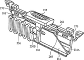
Fig. 5 shows the perspective view according to the preferred embodiment of utility of the present invention.In general, utility 200 comprises 206, one pocket clips 208 of capsule 204, one blade chambers of 202, one eye-catching marker capsules, and an insert cartridges 210, and this chuck has a knife-like switch 212 and two insert cartridges sheets 214.
Fig. 6 A shows the perspective view according to the preferred embodiment of utility of the present invention.Specifically, Fig. 6 A shows the more detailed figure of cutter chamber 206, and this chamber comprises insert cartridges 210.Cutter chamber 206 is generally cylindrical, and two ends 220,224 are arranged, and its medial end portions 220 comprises a blade slit 222, and end 224 holds an eye-catching marker capsule 204 and/or a capsule 202, as below will describing in detail.Should be noted that, also preferably the configuration of the end 220 of cutter chamber 206 is made and held a capsule 202 (not shown).As shown in Fig. 6 A, insert cartridges 210 comprises a blade 216, and this chuck preferably can be removed by utility 200, as below will discussing.By being fitted in the insert cartridges groove, insert cartridges 210 is connected on the cutter chamber 206, chuck groove 218 is defined as space in cutter chamber 206, this space is exposed on the outer surface of cutter chamber (Figure 12).Sheet 214 on two sides of insert cartridges 210 is pressed on the madial wall of insert cartridges groove 218, thereby insert cartridges 210 is fastened on the insert cartridges groove 218.Insert cartridges 210 also comprises a knife-like switch 212 that is connected on the blade 216, and blade 216 moves between the primary importance and the second place.As shown in Fig. 6 A, knife-like switch 212 is in a position, makes blade 216 be stretched out by blade slit 222.On the contrary, Fig. 5 shows knife-like switch 212 and is in a position, is not stretched out by blade slit 222 at this position blade 216.
Fig. 7 shows the perspective view according to a capsule 202 of the preferred embodiments of the present invention.This capsule 202 has top 226, and it can be withdrawn in the capsule 202.Though the discussion here preferably is called a capsule with capsule 202, should be understood that capsule 202 can alternatively be the writing implement of any other application type, this includes but not limited to marker, eye-catching marker, and pencil.In addition, a capsule 202 comprises a link 228, and this end engages with eye-catching marker capsule 204, as shown in Fig. 5 and the 6A-B.In addition, link 228 makes that a capsule 202 can engage (Fig. 6 B) with the end 220 or 224 of cutter chamber 206.The link 228 of capsule 202 is preferably realized the joint with eye-catching marker capsule 204 or end 220,224.Alternatively, link 228 can be by being fixed to the upper with key screw link 228 or any method that other has been known and eye-catching marker capsule 204 or end 220,224 joints.
Fig. 8 shows the perspective view of the eye-catching marker capsule 204 of the preferred embodiments of the present invention.Eye-catching marker capsule 204 preferably has an eye-catching mark writing implement top 232.Though the discussion here preferably is called capsule 204 eye-catching marker capsule, should be understood that, capsule 204 can alternatively be the instrument of any other application type.For example, capsule 204 can alternatively be another kind of writing implement, and this includes but not limited to pen or pencil.Alternatively, capsule 204 can be a kind of survey tool, such as retractible arrowband measurement mechanism, and torch, compass, level meter, bar-code scanner, perhaps other auxiliary equipment.In addition, eye-catching marker capsule 204 also comprises a link 233, and this end engages (Fig. 5) with a capsule 202.In addition, link 233 makes eye-catching marker capsule 204 engage with the end 224 of cutter chamber 206.The most handy screw is fastened to link 233 on the end 224, but also can use any other suitable jockey.
Fig. 9 A shows the perspective view of the insert cartridges 210 of the preferred embodiments of the present invention.Insert cartridges 210 preferably includes an insert cartridges body 234, and it has an orbital groove 238 and 252, one knife-like switches 212 of a guiding window, a blade 216 inside, a pair of 214 and guides 250.Alternatively, insert cartridges 210 ' (Figure 10 A) comprises above-mentioned parts and a safety spring 248, as below will discussing.
Comprise an insert cartridges body 234 in the insert cartridges 210 shown in Fig. 9 A, it has two body side 234A, 234B.With each body side 234A, 234B is joined to one another, and forms insert cartridges body 234, thereby makes body side 234A, and 234B is almost parallel each other.Form body side 234A by molded plastic parts, 234B, and with its punching press formation insert cartridges body 234.Alternatively, body side 234A, 234B can be parts separately, and they are joined to one another, and form insert cartridges body 234.Each body side 234A, 234B has top surface 242A separately, 242B, thus body side 234A, 234B is joined to one another, and forms a top surface that combines 242.
The top surface 242 of insert cartridges body 234 comprises an orbital groove 238, and it makes that knife-like switch 212 can move in the horizontal when insert cartridges 210 is in state of activation (active state) between the primary importance and the second place.The reason that the configuration of insert cartridges 210 is made for safety preferably is in a kind of state of activation and a kind of unactivated state (inactive state).When insert cartridges 210 was in state of activation, blade 216 can move between first and second position in the horizontal.On the contrary, when insert cartridges 210 was in unactivated state, blade 216 can not move between first and second position in the horizontal.The top surface 242 of insert cartridges body 234 preferably includes two protrusion 244 on each end that is arranged on insert cartridges body 234.These protrusion 244 make that as the block piece of knife-like switch 212 knife-like switch 212 can not move to crosses protrusion 244 when insert cartridges 210 is in state of activation.To discuss in more detail below about the state of activation of insert cartridges 210 and the details of unactivated state.
In addition, insert cartridges 210 preferably includes two sheets 214, and these two sheets are fastened on insert cartridges groove 218 with insert cartridges 210.Alternatively, insert cartridges 210 can have only a sheet 214.To make between the inwall of insert cartridges 210 and insert cartridges groove 218 in the configuration of each sheet 214 shown in Fig. 9 A and the 10A and realize snap fit engagement.Insert cartridges 210 is being injected in the process of insert cartridges grooves 218, each sheet 214 is fastened on its position with insert cartridges 210 buckles and with insert cartridges 210, as shown in Fig. 6 A-B.As shown in Fig. 6 A-B, the frictional fit between the inwall separately of sheet 214 and it is fastened to insert cartridges 210 on the insert cartridges groove 218.In the process that insert cartridges 210 is disengaged by insert cartridges groove 218, drive each sheet 214 toward each other, so that produce enough big gap, make the user insert cartridges 210 can be pulled out by insert cartridges groove 218.Each sheet 214 preferably by with insert cartridges body 234A, the 234B identical materials is made, and each sheet has the same feature of spring.Should be noted that, insert cartridges 210 is tightly got back to being not limited to top discussion on the insert cartridges groove 218, can alternatively comprise other assembling type.
The configuration of insert cartridges 210 made to be in a kind of state of activation and a kind of unactivated state.When the embodiment that substitutes was in unactivated state, knife-like switch 212 was positioned at locking groove, and what go out as shown in Fig. 10 A is such, and can not move in any direction in the horizontal.When insert cartridges 210 is not bonded in the insert cartridges groove 218 of cutter chamber 206 (Fig. 6 A), insert cartridges 210 preferably is in nonactivated state.Best, in case insert cartridges 210 is bonded in the insert cartridges groove 218 of cutter chamber 206 (Fig. 6 A), just make insert cartridges be in state of activation.When insert cartridges 210 was in state of activation, knife-like switch 212 can move along orbital groove 238, thereby knife-like switch 212 can advantageously drive blade 216, moves between retracted position and extended position.
To connect the state of activation of discussion insert cartridges 210 and the details of unactivated state with Fig. 9-13 now.Preferred embodiment in the insert cartridges shown in Fig. 9 A 210 is included in two projection 272B that integrally form in the insert cartridges body 234B.Though in Fig. 9 A, do not illustrate, preferably in insert cartridges body 234A, integrally form two projection 272A (not shown) yet.Specifically, projection 272A, the end of 272B (illustrating as the top in Fig. 9 A) is respectively installed to insert cartridges body 234A, on the 234B.With projection 272A, the configuration of the other end of 272B (illustrating as the bottom in Fig. 9 A) is made and is made the bottom face inwards towards each other.With projection 272A, the configuration of the bottom of 272B is made preferably and is pinned each other, thereby the breach of projection 273 (Figure 10 B) can limit blade 216 motion forward.Thereby when insert cartridges 210 was in unactivated state or be not bonded in the insert cartridges groove 218, the configuration of this pinning stoped blade 216 to move along insert cartridges 210 in any direction in the horizontal.Yet with projection 272A, the configuration of 272B is made when making in insert cartridges 210 is bonded on insert cartridges groove 218, and the bottom is separated from each other, and it is separated from each other to move, as shown in Fig. 9 B.
Fig. 9 B shows the exploded chart of one of insert cartridges projection 272 that the projection separating device 278 with the preferred embodiments of the present invention links together.As shown in Fig. 9 B, the inner surface of projection 272 comprises a projection breach 273 that is stretched out by it.Fig. 9 B also shows a projection separating device 278, and the configuration of this separating device is made in cutter chamber 206 (not shown).Cutter chamber of the present invention is preferably in and comprises a projection separating device 278 on each side, and with corresponding projection 272A, 272B engages.Projection separating device 278 has a branch recessing, illustrate with label 279 in Fig. 9 B, thereby projection breach 273 can be fitted in the separating device groove 279.When injecting insert cartridges 210 in the insert cartridges grooves 218, separating device groove 279 engages with projection breach 273, and projection 272 is applied active force makes it leave projection 272 on the another side that is positioned at insert cartridges.Projection 272A, 272B motion away from each other makes insert cartridges 210 be in state of activation, and this is because projection breach 273 no longer limits blade 216 motion forward.
The alternate embodiment of insert cartridges body 234 comprises a locking groove 240 (Figure 11), and this groove is arranged on the top surface 242 of insert cartridges body 234, and is arranged on the middle part along orbital groove 238.This locking groove 240 (Figure 11) has enough sizes, makes that knife-like switch 212 can be fitted into (Figure 11) in the locking groove 240 fully when insert cartridges 210 is in unactivated state.Figure 10 B shows the perspective view according to the incision of the insert cartridges of embodiments of the invention.Insert cartridges 210 comprises a guidance set or guide 250, and this mechanism makes insert cartridges 210 be in state of activation and unactivated state, and drives knife-like switch 212 and blade 216 moves between retracted position and extended position.This guide 250 is parts of knife-like switch 212 self, and comprises two projection piece 250A (Figure 10 A) and 250B (Figure 10 B).Alternatively, guide 250 can be a part that separates, and only includes only a projection piece, and guide 250 is connected on the knife-like switch 212.Projection piece 250A, any one among the 250B passed a blade aperture and stretched, and this hole gauge is decided to be the space of representing with label 254 in Figure 10.As shown in Fig. 10 A, the guiding window 252 that projection piece 250A preferably passes insert cartridges 210 stretches, thereby projection piece 250A can move along guiding window 252 in the horizontal in any direction when insert cartridges 210 is in state of activation.
As shown in Fig. 10 A, the function of the safety spring 248 ' in guiding window 252 is not make insert cartridges 10 be in unactivated state when insert cartridges 210 is connected on the insert cartridges 206.Two side 234A of insert cartridges 210,234B comprises a safety spring 248 '.Alternatively, an only side of insert cartridges 210 comprises a safety spring 248 '.In unactivated state, this safety spring 248 " on projection piece 250A, apply a downward damaged active force, make guide self 250 also be pressed downward.This makes knife-like switch 212 is limited in the locking groove 240 (Figure 11).In addition, guide 250 comprises a guide rod 266, and this guide rod shown in Figure 10 is below knife-like switch 212.In unactivated state, 266 of guide rods as shown in figure 10, and are accommodated between the ledge 268 of locking groove on the ledge 268 of locking groove.As a result, when being in unactivated state, stop knife-like switch 212 and blade 216 to move in the horizontal.Safety spring 248 ' is made by molded plastics, and the material of this material and insert cartridges 210 self is identical.Alternatively, safety spring 248 ' can be made by any other elastomeric material that the same feature of spring is arranged.
Figure 11 shows the perspective view of the incision of cutter chamber of the present invention.Figure 12 shows the perspective view of cutter chamber of the present invention.As shown in Figure 11, cutter chamber 206 comprises a guide spring 256 that is positioned at cutter chamber 206.This guide spring 256 has a fixing end 258 and an abutting end 260, stiff end permanently is installed on the inner surface 264 of cutter chamber 206, and abutting end and horizontal groove 262 matched togethers, as shown in Figure 11 and 12.As shown in Figure 11 and 12, in the side of cutter chamber 206, form this transverse concave groove 262, this groove makes the guide spring 256 transversely length of groove 262 motion in the horizontal.Guide 250 (Fig. 9) is connected on the guide spring 256, thereby guide spring 256 makes insert cartridges 210 be in activation/unactivated state, and realize the level and smooth transverse movement of guide 250, as illustrated in Figure 13 along orbital groove guiding piece 270.For the safety problem of solution instrument 200, guide spring 256 is automatically pressed to guide 250 first and retracted position, and therefore blade 216 is pressed to first and retracted position.Therefore, blade 216 will only just think that the user just rests on extended position to knife-like switch when the second place is pressed.Otherwise as user during not towards second place push broach switch 212, guide spring 256 makes its withdrawal cutter chamber 206 inside with push type broach sheet 216.Alternatively, guide spring 256 can be pressed onto retracted position without spring handle blade 216.
In the embodiment that substitutes, the abutting end 260 of guide spring 256 has the receiving device of " U " font, thereby makes projection piece 250B can be fitted in the receiving device of " U " font of abutting end 260, as illustrated in Figure 13.The configuration of guide spring 256 made rest on a position, in this position, when injecting insert cartridges 210 in the insert cartridges grooves 218 (Figure 12), projection piece 250B automatically is fitted in " U " font receiving device of abutting end 260 of guide spring 256.Also guide spring 256 is arranged on the cutter chamber 206 interior predetermined height, makes guide spring 256 be applied to an active force that makes progress on the guide 250.This upwards active force from guide spring 256 makes insert cartridges 210 enter state of activation by surpassing the opposite downward active force that is applied on the guide 250 by safety spring 248.
Figure 13 shows the cut-away, perspective view of the insert cartridges of alternate embodiment of the present invention.As discussed above, when the insert cartridges groove 218 (Figure 12) that insert cartridges 210 is injected cutter chamber 206 is middle, make insert cartridges 210 enter state of activation.Figure 13 has provided the internal work state of the insert cartridges 210 that is in state of activation.As discussed above, because safety spring 248 is applied to the active force on the guide 250, insert cartridges 210 is in unactivated state.Guide spring 256 is arranged on the cutter chamber 206 interior predetermined height illustrating among the embodiment that substitutes as top, an active force that makes progress is applied on the guide 250.This active force that makes progress enough overcomes the opposite downward active force that is applied by safety spring 248 in the embodiment that substitutes.As shown in Figure 13, in state of activation, locking groove ledge 268 is left in 266 risings of guide bar, and be communicated with orbital groove guiding piece 270.In addition, knife-like switch 212 is raise by locking groove 240, it can be moved in the horizontal along orbital groove 238.Therefore, guide bar 266 is fitted in the orbital groove guiding piece 270, and makes guide 250 to move between the primary importance and the second place.Should be noted that,, be not limited to active force upwards though guide 250 applies an active force that makes progress in alternate embodiment.Therefore, guide 250 can alternatively apply a downward active force, and it is opposite with the active force that makes progress that safety spring 248 is applied.
Insert cartridges 210 of the present invention is preferably disposable.As shown in Fig. 9 A, preferably the configuration of a thin rib 274 is made in the guiding window 252 of insert cartridges 210, and when initial, it is molded on the insert cartridges body 234B.As shown in Fig. 9 A, will approach rib 274 when initial and be installed on the insert cartridges body 234B, and towards the direction of " N " this rib will be set in the mode that makes progress for " new " position.The configuration of thin rib 274 is made when lead arm 276 is shifted thin rib 274 position of onto " U " by the position of the position that makes progress or " N ", and this rib can be disengaged with insert cartridges body 234.This situation is driving blade 216 for the first time and is occurring after the direction top sword sheet of thin rib 274.In other words, after using blade 216 for the first time, lead arm forces thin rib 274 to enter and used position 253.Guiding window 252 is preferably in and comprises a thin rib 274 on each end.Alternatively, can only be installed on the end that guides window 252 approaching rib 274.As top explanation was crossed, blade 216 preferably can move in insert cartridges 210 in the horizontal in any direction, and wherein blade 216 can stretch out in any direction of insert cartridges 210.Therefore, can use the two ends of insert cartridges 210 and blade 216.In case a side rust of blade 216 or no longer can use can be removed insert cartridges 210, and insert chuck again, the position that makes original cutter slit is for to be communicated with cutter slit 222.In case the opposite side of blade 216 is rust or no longer can use also, need to handle insert cartridges 210 because two thin ribs 274 are all moved to used position 253, user to know.
Alternatively, can cover the cutter slit 246 (Fig. 9) of insert cartridges 210 with a kind of thin-film material (not shown), thereby blade 216 can pierce through this film (not shown) after using for the first time blade 216.Cutter slit 246 on each side of insert cartridges body 234 comprises the thin-film material (not shown).Alternatively, thin-film material only can be arranged on one of cutter slit 246.As top explanation was crossed, blade 216 can move in insert cartridges 210 in the horizontal in any direction, and wherein blade 216 can stretch out in any direction of insert cartridges 210.Therefore, can use the two ends of insert cartridges 210 and blade 216.In case a side rust of blade 216 or no longer can use can be removed insert cartridges 210, and insert chuck again, make the position of original cutter slit for to be communicated with cutter slit 222.In case the opposite side of blade 216 is rust or no longer can use also, because two thin-film materials all are pierced, the user will know needs to handle insert cartridges 210.
The preferred assembling of instrument of the present invention will be discussed now.By being linked together, two sides of cutter chamber assemble cutter chamber 206.Subsequently the cap 204 of eye-catching marker is connected on the end 224 of cutter chamber 206.Being connected on the eye-catching marker cap 204 at the lid of the cap for brush shown in Fig. 5 202.Insert cartridges 210 is injected in the insert cartridges groove 218, thereby make sheet 214 can be implemented in the snap fit engagement in the insert cartridges groove 218.
The preferred operation of instrument of the present invention will be discussed now.The insert cartridges 210 that the user will be in unactivated state is arranged in the insert cartridges groove 218.In case insert cartridges 210 is bonded in the insert cartridges groove 218, guide 250 just is fitted in the U font receiving device 260 of guide spring 256.In addition, force projection 272A by engaging with corresponding projection separating device 278,272B is separated from each other, thereby insert cartridges 210 is arranged on state of activation.In order to remove insert cartridges 210, the user exerts pressure to sheet 214 toward each other, thereby produces enough big gap, can be pulled out insert cartridges 210 by the state that engages with cutter chamber 206.As top explanation is crossed, also the cap for brush can be covered 202 and be connected on the end 220 of cutter chamber 206.In case connect, the user can pen with rotary cap 202, is come out in the top of pen.
The present invention has been described, in order that make the principle of understanding structure of the present invention and operation become easy by means of the specific embodiment that comprises details.Do not wish scope for the appended claimed technical scheme of these description restrictions of specific embodiment and details thereof.A bit be tangible below for the people that are familiar with technology: can realize among selected these embodiment changing in order to illustrate, and without departing from the spirit and scope of the present invention.
Claims (45)
1. utility, it comprises:
A. body, it has first end and second end, and wherein, first end and second end are positioned on the opposite ends of body;
B. be positioned the insert cartridges of removing in the body, wherein, the blade in the insert cartridges that can remove is configured to slidably and is stretched out by first end; And
C. first instrument, it is configured on one of first end that optionally is connected to body and second end.
2. according to the described utility of claim 1, it is characterized in that the insert cartridges that can remove also comprises the knife-like switch that is connected on the blade, wherein, knife-like switch makes blade can slide between extended position and retracted position with respect to body.
3. according to the described utility of claim 2, it is characterized in that when only just thinking that insert cartridges is bonded in the body, knife-like switch just can make blade move to extended position by retracted position.
4. according to the described utility of claim 2, it is characterized in that described utility also comprises the spring mechanism that is connected on the knife-like switch, be used for blade is biased to retracted position.
5. according to the described utility of claim 1, it is characterized in that described utility also comprises second instrument, this second instrument is configured to and can optionally be connected on first instrument.
6. according to the described utility of claim 5, it is characterized in that second instrument also is configured on one of first end that optionally is connected to body and second end.
7. according to the described utility of claim 1, it is characterized in that first instrument is a writing implement.
8. according to the described utility of claim 5, it is characterized in that second instrument is a writing implement.
9. according to the described utility of claim 5, it is characterized in that second instrument is a measuring instrument.
10. according to the described utility of claim 9, it is characterized in that measuring instrument is to comprise a kind of in the group of following instrument: retractible arrowband measurement mechanism, level meter, compass, and bar-code scanner.
11., it is characterized in that second instrument is a lighting device according to the described utility of claim 5.
12., it is characterized in that body comprises the insert cartridges groove according to the described utility of claim 1, be used for holding the insert cartridges that to remove.
13. according to the described utility of claim 12, it is characterized in that insert cartridges comprises pieces of sheet, be used for engaging and make insert cartridges and insert cartridges groove to be disengaged insert cartridges and insert cartridges groove by being clasped.
14., it is characterized in that insert cartridges also comprises according to the described utility of claim 2:
A. the first blade body side; And
B. be communicated with the first blade body side and be positioned to basically the second blade body side with the first blade body parallel sided, wherein, recess is between the first blade body side and the second blade body side, be used for putting blade, insert cartridges comprises a kind of thin-film material, thin-film material is configured to and covers the cutter slit be communicated with recess, feasible when initially blade being moved to extended position by retracted position the blade punctures film.
15., it is characterized in that described utility also comprises the clip that is connected on the body according to the described utility of claim 1.
16., it is characterized in that described body is roughly cylindrical according to the described utility of claim 1, and in described body, comprise the insert cartridges groove.
17., it is characterized in that the insert cartridges that can remove comprises the knife-like switch that is connected on the blade according to the described utility of claim 16, wherein, when not using, knife-like switch makes blade automatically be withdrawn in the body.
18., it is characterized in that described utility also comprises second instrument according to the described utility of claim 16, this second instrument is configured to and is connected on first instrument.
19. according to the described utility of claim 18, it is characterized in that, on second instrument is configured to and one of optionally is connected in first end and second end.
20., it is characterized in that first instrument is a writing implement according to the described utility of claim 16.
21., it is characterized in that second instrument is a measuring instrument according to the described utility of claim 18.
22., it is characterized in that second instrument is a writing implement according to the described utility of claim 18.
23., it is characterized in that measuring instrument is to comprise a kind of in the group of following instrument: retractible arrowband measurement mechanism, level meter, compass, and bar-code scanner according to the described utility of claim 21.
24., it is characterized in that second instrument is a lighting device according to the described utility of claim 18.
Be fitted in the corresponding insert cartridges groove 25. the insert cartridges that can remove, this chuck are configured to, this insert cartridges comprises:
A. the insert cartridges body that can remove has recess in body, and this body has the cutter slit that is communicated with recess;
B. can be positioned on the blade in the recess, blade is configured to and can slides with respect to described insert cartridges body between open position and closed position;
C. the guidance set that is connected with blade, wherein, this guidance set drives blade and moves between closed position and open position; And
D. pieces of sheet is used for engaging and make insert cartridges and insert cartridges groove to be disengaged insert cartridges and insert cartridges groove.
26., it is characterized in that the body of insert cartridges also comprises according to the described insert cartridges of removing of claim 25:
A. the first blade body side; And
B. be communicated with the first blade body side and be positioned to basically the second blade body side with the first blade body parallel sided, wherein, recess is between the first blade body side and the second blade body side, the body of insert cartridges comprises a kind of thin-film material, thin-film material is configured on the cutter slit, makes blade punctures film when initially blade being moved to open position by the closed position.
27., it is characterized in that the insert cartridges groove also comprises guide spring according to the described utility of claim 25, wherein, guide spring forces blade to be withdrawn into the closed position.
28., it is characterized in that when only just thinking that insert cartridges is bonded in the insert cartridges groove, blade just can move according to the described insert cartridges of removing of claim 25 between closed position and open position.
29. according to the described insert cartridges of removing of claim 28, it is characterized in that, the described insert cartridges of removing also comprises safety spring, be used for when insert cartridges and insert cartridges groove are disengaged, guidance set being applied first active force, wherein, when first active force is applied on the guidance set, will stop blade movement.
30. a utility, it comprises:
A. body;
B. be connected to first housing on this body, wherein, first housing contains cutting tool, and this cutting tool is configured to slidably and is stretched out by first housing; And
C. be connected to second housing on the body, described second housing has first end and second end, wherein, first end and second end are reciprocally located, second housing is configured between the primary importance and the second place and rotates, and keeps connecting described body simultaneously, wherein, first end is positioned in the body at the primary importance place, and is positioned at second place place first end and leaves described body.
31., it is characterized in that described utility also comprises the knife-like switch that is connected on the cutting tool according to the described utility of claim 30, wherein, when not using, knife-like switch makes cutting tool automatically be withdrawn in the utility.
32., it is characterized in that second housing also comprises first instrument that is extended by first end according to the described utility of claim 30.
33., it is characterized in that second housing also comprises second instrument that is extended by second end according to the described utility of claim 32.
34., it is characterized in that first instrument is a writing implement according to the described utility of claim 32.
35., it is characterized in that second instrument is a measuring instrument according to the described utility of claim 33.
36., it is characterized in that measuring instrument is to comprise a kind of in the group of following instrument: retractible arrowband measurement mechanism, level meter, compass, and bar-code scanner according to the described utility of claim 35.
37., it is characterized in that second instrument is a lighting device according to the described utility of claim 33.
38., it is characterized in that described utility also is included in the container that integrally forms in this utility according to the described utility of claim 30, this container is used for putting an end of selecting in the end that is arranged on second housing in this utility.
39., it is characterized in that described utility also is included in the track that integrally forms in the body according to the described utility of claim 30, wherein, second housing is connected on this track, and second housing can be along this orbital motion.
40. according to the described utility of claim 30, it is characterized in that, described first housing comprises the cutter chamber, and described second housing comprises the chuck unit, there are first writing implement and second writing implement in this chuck unit, wherein, first writing implement and second writing implement are provided with relative to one another.
41., it is characterized in that described utility also comprises the knife-like switch that is connected on the cutting tool according to the described utility of claim 40, wherein, when not using, knife-like switch makes cutting tool automatically be withdrawn in the cutter chamber.
42., it is characterized in that first writing implement is a pen according to the described utility of claim 40.
43., it is characterized in that second writing implement is eye-catching marker according to the described utility of claim 40.
44., it is characterized in that described utility also is included in the container that integrally forms in the body according to the described utility of claim 40, this container is used for putting one of them end that is arranged on intrinsic chuck unit.
45., it is characterized in that described utility has the track that integrally forms according to the described utility of claim 40 in body, wherein, the chuck unit is connected on this track, and the chuck unit can be along this orbital motion.
Applications Claiming Priority (7)
| Application Number | Priority Date | Filing Date | Title |
|---|---|---|---|
| US31213101P | 2001-08-13 | 2001-08-13 | |
| US60/312,131 | 2001-08-13 | ||
| US10/184,303 | 2002-06-26 | ||
| US10/184,303 US7774941B2 (en) | 2001-08-13 | 2002-06-26 | Multi-tasking utility tool |
| US10/218,388 US6874188B2 (en) | 2001-08-13 | 2002-08-12 | Multi-tasking utility tool |
| US10/218,388 | 2002-08-12 | ||
| PCT/US2002/025753 WO2003015994A2 (en) | 2001-08-13 | 2002-08-13 | Multi-tasking utility tool |
Publications (2)
| Publication Number | Publication Date |
|---|---|
| CN1761555A CN1761555A (en) | 2006-04-19 |
| CN1761555B true CN1761555B (en) | 2010-06-16 |
Family
ID=46150185
Family Applications (1)
| Application Number | Title | Priority Date | Filing Date |
|---|---|---|---|
| CN028203038A Expired - Fee Related CN1761555B (en) | 2001-08-13 | 2002-08-13 | Practical tool and movable blade chuck |
Country Status (12)
| Country | Link |
|---|---|
| US (2) | US6874188B2 (en) |
| EP (2) | EP1417077B1 (en) |
| JP (2) | JP4528525B2 (en) |
| CN (1) | CN1761555B (en) |
| AT (2) | ATE507943T1 (en) |
| AU (1) | AU2002355959A1 (en) |
| CA (1) | CA2459173C (en) |
| DE (2) | DE60239969D1 (en) |
| ES (1) | ES2281532T3 (en) |
| HK (1) | HK1067582A1 (en) |
| MX (1) | MXPA04001336A (en) |
| WO (1) | WO2003015994A2 (en) |
Families Citing this family (26)
| Publication number | Priority date | Publication date | Assignee | Title |
|---|---|---|---|---|
| US7237340B2 (en) * | 2001-08-13 | 2007-07-03 | Wagic, Inc. | Multi-tasking utility tool |
| US6874188B2 (en) * | 2001-08-13 | 2005-04-05 | Wampum | Multi-tasking utility tool |
| US7774941B2 (en) * | 2001-08-13 | 2010-08-17 | Wampum Llc | Multi-tasking utility tool |
| AU2003274299A1 (en) * | 2003-07-02 | 2005-01-21 | Penife International Limited | Combined pen and knife implement |
| US7125186B1 (en) | 2003-08-15 | 2006-10-24 | Thomas Richard Stokes | Writing instrument with enclosing structure |
| US7278752B2 (en) * | 2005-03-09 | 2007-10-09 | Chemical Light Inc. | Device for providing internal illumination of live flowers and other products |
| US7316070B2 (en) * | 2005-11-15 | 2008-01-08 | Irwin Industrial Tool Company | Self-retracting utility knife |
| US8245753B2 (en) * | 2006-01-05 | 2012-08-21 | Haemerle Richard R | Hand tools for applying masking tape and the like to various surfaces |
| US20070223214A1 (en) * | 2006-03-26 | 2007-09-27 | Ming-Hsien Yen | Telescopic tool pen with an illumination device |
| US8191192B1 (en) | 2006-04-25 | 2012-06-05 | Barker Richard W | Modular tools |
| US20080086895A1 (en) * | 2006-10-17 | 2008-04-17 | Thomas Jerald Parks | Utility knife with integrated hole punch |
| US7494431B2 (en) * | 2007-05-07 | 2009-02-24 | Austin Wang | 3-in-1 divot tool |
| US20090016801A1 (en) * | 2007-07-09 | 2009-01-15 | Spark Gold Co. | Handy tool pen |
| US8069571B2 (en) * | 2008-04-29 | 2011-12-06 | Pacific Handy Cutter, Inc. | Spring back safety and film cutter |
| US8201336B2 (en) | 2008-05-02 | 2012-06-19 | Olympia Tools International, Inc. | Retractable utility knife |
| US7591037B1 (en) | 2008-06-13 | 2009-09-22 | Carmen Alvarado-Biswell | Four-in-one multi-component combination tool to facilitate forming and sealing cartons and boxes |
| US8695221B2 (en) | 2008-08-21 | 2014-04-15 | Wen Hao | Utility knife with extended travel carriage |
| US20100186175A1 (en) * | 2009-01-29 | 2010-07-29 | Brad Alan Watson | E.e.z.z. ultimate survival tool |
| CN201440247U (en) * | 2009-06-05 | 2010-04-21 | 健博贸易有限公司 | Writing pen |
| US9592599B2 (en) * | 2012-06-06 | 2017-03-14 | Adam Pauze | Drywall tool and method of using the same |
| CA2888196C (en) * | 2012-10-15 | 2021-07-27 | Michael Kildevaeld | Marking blade |
| ES2664333T3 (en) | 2012-12-05 | 2018-04-19 | PenBlade, Inc. | Safety cutting device |
| US9315067B2 (en) | 2014-04-14 | 2016-04-19 | II Curtis J. Chauvin | Combined writing utensil and light emitter assembly |
| USD867847S1 (en) | 2017-04-11 | 2019-11-26 | Pacific Handy Cutter, Inc. | Embedded blade cutter |
| USD867097S1 (en) | 2017-04-11 | 2019-11-19 | Pacific Handy Cutter, Inc. | Embedded blade cutter |
| US11090971B1 (en) * | 2020-11-05 | 2021-08-17 | Charles Yerry | Pen cap / low light adjustment tool for laser aiming devices |
Citations (6)
| Publication number | Priority date | Publication date | Assignee | Title |
|---|---|---|---|---|
| US1368944A (en) * | 1920-08-12 | 1921-02-15 | Kurose Kaemon | Combination instrument |
| US4635309A (en) * | 1985-05-17 | 1987-01-13 | Larsen Peter L | Multiple use hand tool |
| US5450775A (en) * | 1994-01-07 | 1995-09-19 | Kozak; Burton | Multi-function driving tool |
| US5809600A (en) * | 1996-01-05 | 1998-09-22 | Wenger Sa | Mutifunctional tool able to receive removable attachments |
| US5813121A (en) * | 1996-06-17 | 1998-09-29 | Allway Tools, Inc. | Automatically retractable utility knife |
| US5887306A (en) * | 1997-05-29 | 1999-03-30 | Huang; Yung Hsu | Tool combination having screw driver and knife |
Family Cites Families (82)
| Publication number | Priority date | Publication date | Assignee | Title |
|---|---|---|---|---|
| US1444155A (en) | 1922-05-11 | 1923-02-06 | Peter R Joecensen | Combined pen and blade holder |
| US2980996A (en) * | 1958-05-08 | 1961-04-25 | Rudolph F Beran | Sheathed tool with detachable blade |
| US3657812A (en) * | 1970-09-28 | 1972-04-25 | G & L Ind Inc | Retractible tool holder |
| US3660895A (en) | 1971-01-11 | 1972-05-09 | Stanley Works New Britain The | Retractable utility knife |
| JPS5218319Y2 (en) * | 1973-12-11 | 1977-04-25 | ||
| US4068375A (en) | 1976-12-08 | 1978-01-17 | The Stanley Works | Heavy duty retractable blade utility knife |
| JPS54136699U (en) * | 1978-03-16 | 1979-09-21 | ||
| JPS54136699A (en) | 1978-04-14 | 1979-10-23 | Matsushita Electric Ind Co Ltd | Preparing semiconductor porcelain element |
| JPS5753494Y2 (en) * | 1978-06-28 | 1982-11-19 | ||
| JPS56106162U (en) * | 1980-01-17 | 1981-08-18 | ||
| JPS57161965A (en) | 1981-03-30 | 1982-10-05 | Fujitsu Ltd | Pos terminal device |
| JPS57161965U (en) * | 1981-04-04 | 1982-10-12 | ||
| JPS5959970U (en) * | 1982-10-09 | 1984-04-19 | 株式会社貝印刃物開発センター | cutter knife |
| JPS59136663U (en) * | 1983-03-01 | 1984-09-12 | 初谷 秀雄 | A globe in which color filters inside the globe are rotated by a motor to represent the revolution of the earth. |
| US4602397A (en) | 1984-11-23 | 1986-07-29 | Chao Jui H | Writing instrument |
| US4854045A (en) | 1985-01-01 | 1989-08-08 | Wenger Sa | Modular pocketknife |
| JPS61124276U (en) * | 1985-01-24 | 1986-08-05 | ||
| US4744146A (en) | 1986-02-19 | 1988-05-17 | Pacific Handy Cutter, Inc. | Adjustable-blade safety knife with carton-cutting guide |
| DE3622342A1 (en) | 1986-07-03 | 1988-01-14 | Beermann Kg Martor Argentax | KNIFE |
| JPS6363497U (en) * | 1986-10-15 | 1988-04-26 | ||
| US4792883A (en) | 1987-07-20 | 1988-12-20 | Ackerman Archie W | Runners baton bat |
| JPH01128898A (en) * | 1987-11-13 | 1989-05-22 | Zebra Pen Corp | Composite stationery |
| IT214148Z2 (en) * | 1988-01-13 | 1990-04-02 | Rpr Righella Rosso W & C Sas | WRITING AND DRAWING TOOL |
| US4891881A (en) | 1988-04-12 | 1990-01-09 | Mills Norman T | Combined cutting tool and sharpener |
| US4890387A (en) * | 1989-03-10 | 1990-01-02 | Canino Serafino S | Drywall utility knife |
| JPH0320990U (en) * | 1989-07-06 | 1991-02-28 | ||
| US5025520A (en) * | 1989-07-18 | 1991-06-25 | Watkins William C | Combined tool and method for using same |
| JPH0335634U (en) * | 1989-08-17 | 1991-04-08 | ||
| JPH03116992U (en) * | 1990-03-15 | 1991-12-03 | ||
| US5059126A (en) | 1990-05-09 | 1991-10-22 | Kimball Dan V | Sound association and learning system |
| US6390370B1 (en) | 1990-11-15 | 2002-05-21 | Symbol Technologies, Inc. | Light beam scanning pen, scan module for the device and method of utilization |
| JPH08249Y2 (en) * | 1991-03-07 | 1996-01-10 | 株式会社錦味 | Container with drawer |
| JPH0588385A (en) | 1991-07-31 | 1993-04-09 | Fuji Xerox Co Ltd | Dip coating equipment |
| US5174028A (en) | 1991-10-30 | 1992-12-29 | Seltzer Jr Roger E | Utility knife |
| JPH0541884U (en) * | 1991-11-06 | 1993-06-08 | 未来工業株式会社 | A quick-drying writing instrument with a cutter |
| US5386632A (en) | 1993-01-12 | 1995-02-07 | Pacific Handy Cutter, Inc. | Ergonomic utility knife/box cutter and method of making |
| US5396820A (en) | 1993-01-15 | 1995-03-14 | Baker; David R. | Open end wrench with removable handle |
| US6119944A (en) | 1997-02-03 | 2000-09-19 | Symbol Technologies, Inc. | Down-loadable hand-held optical reader |
| US5315760A (en) | 1993-05-17 | 1994-05-31 | Emerson Stephen W | Razor knife with built-in pencil sharpener |
| US5342379A (en) | 1993-06-01 | 1994-08-30 | Volinsky Fredric G | Safety scalpel |
| US5402575A (en) * | 1994-05-23 | 1995-04-04 | Maxcy; Richard B. | Folding knife provided with an accessory |
| US5557818A (en) * | 1994-11-14 | 1996-09-24 | Leon; Michael | Utility pen-knife |
| US5711194A (en) * | 1995-05-26 | 1998-01-27 | Anderson; Wayne | Folding knife and interchangeable bit screwdriver |
| DE19623167A1 (en) | 1996-05-30 | 1996-11-21 | Gaul Markus Dipl Psych | General-purpose knife with writing function |
| JP3035634U (en) | 1996-09-10 | 1997-03-28 | 榮宗 呉 | Multifunctional pen |
| JPH1094683A (en) * | 1996-09-25 | 1998-04-14 | N T Kk | Cutter |
| US5945656A (en) | 1997-05-27 | 1999-08-31 | Lemelson; Jerome H. | Apparatus and method for stand-alone scanning and audio generation from printed material |
| US5870828A (en) * | 1997-06-04 | 1999-02-16 | Violex-Bic, S.A. | Utility knife system |
| DE29717194U1 (en) * | 1997-09-26 | 1998-02-05 | Mvg Vertrieb Gmbh | Multifunctional rescue device |
| US5939702A (en) | 1997-10-10 | 1999-08-17 | Motorola, Inc. | Writing implement having an integrated optical reader |
| TW341539B (en) | 1997-10-24 | 1998-10-01 | Allway Tools | Automatically retractable utility knife with plastic spring |
| US6050490A (en) | 1997-10-31 | 2000-04-18 | Hewlett-Packard Company | Handheld writing device and related data entry system |
| JPH11179072A (en) | 1997-12-18 | 1999-07-06 | Kds:Kk | Cutter knife |
| US5955719A (en) | 1997-12-19 | 1999-09-21 | A. T. Cross Company | Data/pen well |
| US6446871B1 (en) | 1997-12-19 | 2002-09-10 | A.T. Cross Company | Method and apparatus for storing reference codes in a writing instrument and for retrieving information identifed by the reference codes |
| US5957601A (en) * | 1998-02-23 | 1999-09-28 | Weiss; Marla | Multi-segment writing implement |
| US6330976B1 (en) | 1998-04-01 | 2001-12-18 | Xerox Corporation | Marking medium area with encoded identifier for producing action through network |
| US6273582B1 (en) | 1999-05-12 | 2001-08-14 | Swiss Army Brands, Inc. | Compact multiple function tool |
| US6263577B1 (en) | 1998-10-06 | 2001-07-24 | American Safety Razor | Automatic spring retractable utility knife |
| US6779425B2 (en) | 2000-11-27 | 2004-08-24 | Ctech Ag | Multipurpose handheld implement |
| CN2385375Y (en) | 1998-12-30 | 2000-06-28 | 王登福 | Electronic calculating pen |
| GB9909317D0 (en) * | 1999-04-23 | 1999-06-16 | Dymark Limited | Cutting tool |
| JP2001087569A (en) | 1999-09-20 | 2001-04-03 | Masato Yamamoto | Cutter knife with width cutting tool |
| US6363614B1 (en) * | 1999-10-12 | 2002-04-02 | George H. Umstead | Combination utility retractable saw and knife device |
| US6276014B1 (en) * | 2000-02-07 | 2001-08-21 | Shu-Chen Lee | Tool coupler/knife combination |
| US7075000B2 (en) | 2000-06-29 | 2006-07-11 | Musicgenome.Com Inc. | System and method for prediction of musical preferences |
| JP2002082973A (en) | 2000-09-08 | 2002-03-22 | Sony Corp | System and method for retrieving information, device and method for supplying retrieval information, device and method for displaying retrieval information, and recording medium recording the retrieval information displaying method |
| US6454427B1 (en) | 2000-11-27 | 2002-09-24 | Kun-Chen Chen | Illuminating utility knife with easy-access spare blade drawer |
| US7125145B2 (en) | 2000-12-26 | 2006-10-24 | Taylor Cutlery Llc | Multi-purpose equipment |
| US6487778B1 (en) | 2001-03-15 | 2002-12-03 | Allway Tools, Inc. | Utility knife with pressure reducing slot |
| US6481628B2 (en) | 2001-04-10 | 2002-11-19 | Kenneth Liou | Pen-type barcode scanner |
| US6966113B2 (en) | 2001-07-23 | 2005-11-22 | Repetto Llc | Utility knife |
| US6874188B2 (en) | 2001-08-13 | 2005-04-05 | Wampum | Multi-tasking utility tool |
| US7237340B2 (en) | 2001-08-13 | 2007-07-03 | Wagic, Inc. | Multi-tasking utility tool |
| US7774941B2 (en) | 2001-08-13 | 2010-08-17 | Wampum Llc | Multi-tasking utility tool |
| WO2004030352A1 (en) | 2002-09-26 | 2004-04-08 | Sharp Kabushiki Kaisha | Data output device for determining candidate of adequate data |
| US20060030289A1 (en) | 2002-10-24 | 2006-02-09 | Napc, Llc | Writing instrument with display module capable of receiving messages via radio |
| AT500390B1 (en) | 2002-10-30 | 2008-12-15 | Victorinox Ag | POCKET TOOL |
| US6868571B1 (en) | 2003-10-08 | 2005-03-22 | Credo Technology Corporation | Memo recorder/tape measuring module |
| AT500097B9 (en) | 2003-10-17 | 2007-08-15 | Victorinox Ag | POCKET TOOL |
| WO2006031808A2 (en) | 2004-09-14 | 2006-03-23 | Avello, Llc | Powered utility knife |
| US20060212058A1 (en) | 2005-03-18 | 2006-09-21 | Ilija Djordjevic | Disposable safety surgical blade |
-
2002
- 2002-08-12 US US10/218,388 patent/US6874188B2/en not_active Expired - Lifetime
- 2002-08-13 EP EP02752831A patent/EP1417077B1/en not_active Expired - Lifetime
- 2002-08-13 ES ES02752831T patent/ES2281532T3/en not_active Expired - Lifetime
- 2002-08-13 AU AU2002355959A patent/AU2002355959A1/en not_active Abandoned
- 2002-08-13 CA CA2459173A patent/CA2459173C/en not_active Expired - Fee Related
- 2002-08-13 DE DE60239969T patent/DE60239969D1/en not_active Expired - Lifetime
- 2002-08-13 EP EP07004527A patent/EP1834740B1/en not_active Expired - Lifetime
- 2002-08-13 DE DE60219483T patent/DE60219483T2/en not_active Expired - Lifetime
- 2002-08-13 WO PCT/US2002/025753 patent/WO2003015994A2/en active IP Right Grant
- 2002-08-13 JP JP2003520534A patent/JP4528525B2/en not_active Expired - Fee Related
- 2002-08-13 CN CN028203038A patent/CN1761555B/en not_active Expired - Fee Related
- 2002-08-13 AT AT07004527T patent/ATE507943T1/en not_active IP Right Cessation
- 2002-08-13 MX MXPA04001336A patent/MXPA04001336A/en active IP Right Grant
- 2002-08-13 AT AT02752831T patent/ATE359155T1/en not_active IP Right Cessation
-
2004
- 2004-06-29 US US10/881,776 patent/US8359754B2/en not_active Expired - Fee Related
- 2004-11-11 HK HK04108918A patent/HK1067582A1/en not_active IP Right Cessation
-
2008
- 2008-07-14 JP JP2008183136A patent/JP4970370B2/en not_active Expired - Lifetime
Patent Citations (6)
| Publication number | Priority date | Publication date | Assignee | Title |
|---|---|---|---|---|
| US1368944A (en) * | 1920-08-12 | 1921-02-15 | Kurose Kaemon | Combination instrument |
| US4635309A (en) * | 1985-05-17 | 1987-01-13 | Larsen Peter L | Multiple use hand tool |
| US5450775A (en) * | 1994-01-07 | 1995-09-19 | Kozak; Burton | Multi-function driving tool |
| US5809600A (en) * | 1996-01-05 | 1998-09-22 | Wenger Sa | Mutifunctional tool able to receive removable attachments |
| US5813121A (en) * | 1996-06-17 | 1998-09-29 | Allway Tools, Inc. | Automatically retractable utility knife |
| US5887306A (en) * | 1997-05-29 | 1999-03-30 | Huang; Yung Hsu | Tool combination having screw driver and knife |
Also Published As
| Publication number | Publication date |
|---|---|
| EP1834740A3 (en) | 2008-03-26 |
| JP2008296030A (en) | 2008-12-11 |
| DE60219483T2 (en) | 2007-12-20 |
| EP1834740A2 (en) | 2007-09-19 |
| JP4970370B2 (en) | 2012-07-04 |
| JP4528525B2 (en) | 2010-08-18 |
| EP1417077A2 (en) | 2004-05-12 |
| AU2002355959A1 (en) | 2003-03-03 |
| EP1834740B1 (en) | 2011-05-04 |
| CN1761555A (en) | 2006-04-19 |
| EP1417077B1 (en) | 2007-04-11 |
| ES2281532T3 (en) | 2007-10-01 |
| MXPA04001336A (en) | 2004-10-27 |
| EP1417077A4 (en) | 2005-03-09 |
| WO2003015994A2 (en) | 2003-02-27 |
| CA2459173C (en) | 2011-09-20 |
| WO2003015994A3 (en) | 2003-08-28 |
| US20040231162A1 (en) | 2004-11-25 |
| DE60239969D1 (en) | 2011-06-16 |
| HK1067582A1 (en) | 2005-04-15 |
| US8359754B2 (en) | 2013-01-29 |
| DE60219483D1 (en) | 2007-05-24 |
| US20030066137A1 (en) | 2003-04-10 |
| ATE507943T1 (en) | 2011-05-15 |
| WO2003015994A9 (en) | 2003-04-24 |
| JP2004538094A (en) | 2004-12-24 |
| ATE359155T1 (en) | 2007-05-15 |
| US6874188B2 (en) | 2005-04-05 |
| CA2459173A1 (en) | 2003-02-27 |
Similar Documents
| Publication | Publication Date | Title |
|---|---|---|
| CN1761555B (en) | Practical tool and movable blade chuck | |
| US20190015997A1 (en) | Multi-tasking utility tool | |
| CN202878425U (en) | Handsaw and saw blade used together with the handsaw | |
| KR19990036022A (en) | Multipurpose hand-held tool in the form of a pocket knife | |
| EP1872968B1 (en) | Slide pen | |
| US7774941B2 (en) | Multi-tasking utility tool | |
| EP2808175B1 (en) | Eraser | |
| JP5728991B2 (en) | stamp | |
| TWI386293B (en) | Handheld cutting tool and removable blade cartridge | |
| US2642039A (en) | Eyebrow pencil | |
| JP3134597U (en) | Adhesive cellophane tape holder | |
| JP3135565U (en) | Envelope opening tool | |
| JP3127268U (en) | Cutter with folding blade storage | |
| TWI273958B (en) | Handheld and cutting tools | |
| JP2022073256A (en) | Holder | |
| JP2006136395A (en) | Cutter knife for slush quilt |
Legal Events
| Date | Code | Title | Description |
|---|---|---|---|
| C06 | Publication | ||
| PB01 | Publication | ||
| C10 | Entry into substantive examination | ||
| SE01 | Entry into force of request for substantive examination | ||
| C14 | Grant of patent or utility model | ||
| GR01 | Patent grant | ||
| CF01 | Termination of patent right due to non-payment of annual fee |
Granted publication date: 20100616 Termination date: 20140813 |
|
| EXPY | Termination of patent right or utility model |