CN1865860B - Navigation apparatus - Google Patents
Navigation apparatus Download PDFInfo
- Publication number
- CN1865860B CN1865860B CN2006100930307A CN200610093030A CN1865860B CN 1865860 B CN1865860 B CN 1865860B CN 2006100930307 A CN2006100930307 A CN 2006100930307A CN 200610093030 A CN200610093030 A CN 200610093030A CN 1865860 B CN1865860 B CN 1865860B
- Authority
- CN
- China
- Prior art keywords
- operating rod
- map
- mentioned
- rotation
- road
- Prior art date
- Legal status (The legal status is an assumption and is not a legal conclusion. Google has not performed a legal analysis and makes no representation as to the accuracy of the status listed.)
- Expired - Fee Related
Links
Images


Classifications
-
- G—PHYSICS
- G01—MEASURING; TESTING
- G01C—MEASURING DISTANCES, LEVELS OR BEARINGS; SURVEYING; NAVIGATION; GYROSCOPIC INSTRUMENTS; PHOTOGRAMMETRY OR VIDEOGRAMMETRY
- G01C21/00—Navigation; Navigational instruments not provided for in groups G01C1/00 - G01C19/00
- G01C21/26—Navigation; Navigational instruments not provided for in groups G01C1/00 - G01C19/00 specially adapted for navigation in a road network
- G01C21/34—Route searching; Route guidance
- G01C21/36—Input/output arrangements for on-board computers
- G01C21/3664—Details of the user input interface, e.g. buttons, knobs or sliders, including those provided on a touch screen; remote controllers; input using gestures
-
- G—PHYSICS
- G01—MEASURING; TESTING
- G01C—MEASURING DISTANCES, LEVELS OR BEARINGS; SURVEYING; NAVIGATION; GYROSCOPIC INSTRUMENTS; PHOTOGRAMMETRY OR VIDEOGRAMMETRY
- G01C21/00—Navigation; Navigational instruments not provided for in groups G01C1/00 - G01C19/00
- G01C21/26—Navigation; Navigational instruments not provided for in groups G01C1/00 - G01C19/00 specially adapted for navigation in a road network
- G01C21/34—Route searching; Route guidance
- G01C21/36—Input/output arrangements for on-board computers
- G01C21/3667—Display of a road map
- G01C21/367—Details, e.g. road map scale, orientation, zooming, illumination, level of detail, scrolling of road map or positioning of current position marker
-
- G—PHYSICS
- G05—CONTROLLING; REGULATING
- G05G—CONTROL DEVICES OR SYSTEMS INSOFAR AS CHARACTERISED BY MECHANICAL FEATURES ONLY
- G05G9/00—Manually-actuated control mechanisms provided with one single controlling member co-operating with two or more controlled members, e.g. selectively, simultaneously
- G05G9/02—Manually-actuated control mechanisms provided with one single controlling member co-operating with two or more controlled members, e.g. selectively, simultaneously the controlling member being movable in different independent ways, movement in each individual way actuating one controlled member only
- G05G9/04—Manually-actuated control mechanisms provided with one single controlling member co-operating with two or more controlled members, e.g. selectively, simultaneously the controlling member being movable in different independent ways, movement in each individual way actuating one controlled member only in which movement in two or more ways can occur simultaneously
- G05G9/047—Manually-actuated control mechanisms provided with one single controlling member co-operating with two or more controlled members, e.g. selectively, simultaneously the controlling member being movable in different independent ways, movement in each individual way actuating one controlled member only in which movement in two or more ways can occur simultaneously the controlling member being movable by hand about orthogonal axes, e.g. joysticks
- G05G9/04785—Manually-actuated control mechanisms provided with one single controlling member co-operating with two or more controlled members, e.g. selectively, simultaneously the controlling member being movable in different independent ways, movement in each individual way actuating one controlled member only in which movement in two or more ways can occur simultaneously the controlling member being movable by hand about orthogonal axes, e.g. joysticks the controlling member being the operating part of a switch arrangement
- G05G9/04788—Manually-actuated control mechanisms provided with one single controlling member co-operating with two or more controlled members, e.g. selectively, simultaneously the controlling member being movable in different independent ways, movement in each individual way actuating one controlled member only in which movement in two or more ways can occur simultaneously the controlling member being movable by hand about orthogonal axes, e.g. joysticks the controlling member being the operating part of a switch arrangement comprising additional control elements
- G05G9/04792—Manually-actuated control mechanisms provided with one single controlling member co-operating with two or more controlled members, e.g. selectively, simultaneously the controlling member being movable in different independent ways, movement in each individual way actuating one controlled member only in which movement in two or more ways can occur simultaneously the controlling member being movable by hand about orthogonal axes, e.g. joysticks the controlling member being the operating part of a switch arrangement comprising additional control elements for rotary control around the axis of the controlling member
-
- G—PHYSICS
- G05—CONTROLLING; REGULATING
- G05G—CONTROL DEVICES OR SYSTEMS INSOFAR AS CHARACTERISED BY MECHANICAL FEATURES ONLY
- G05G9/00—Manually-actuated control mechanisms provided with one single controlling member co-operating with two or more controlled members, e.g. selectively, simultaneously
- G05G9/02—Manually-actuated control mechanisms provided with one single controlling member co-operating with two or more controlled members, e.g. selectively, simultaneously the controlling member being movable in different independent ways, movement in each individual way actuating one controlled member only
- G05G9/04—Manually-actuated control mechanisms provided with one single controlling member co-operating with two or more controlled members, e.g. selectively, simultaneously the controlling member being movable in different independent ways, movement in each individual way actuating one controlled member only in which movement in two or more ways can occur simultaneously
- G05G9/047—Manually-actuated control mechanisms provided with one single controlling member co-operating with two or more controlled members, e.g. selectively, simultaneously the controlling member being movable in different independent ways, movement in each individual way actuating one controlled member only in which movement in two or more ways can occur simultaneously the controlling member being movable by hand about orthogonal axes, e.g. joysticks
- G05G9/04785—Manually-actuated control mechanisms provided with one single controlling member co-operating with two or more controlled members, e.g. selectively, simultaneously the controlling member being movable in different independent ways, movement in each individual way actuating one controlled member only in which movement in two or more ways can occur simultaneously the controlling member being movable by hand about orthogonal axes, e.g. joysticks the controlling member being the operating part of a switch arrangement
- G05G9/04788—Manually-actuated control mechanisms provided with one single controlling member co-operating with two or more controlled members, e.g. selectively, simultaneously the controlling member being movable in different independent ways, movement in each individual way actuating one controlled member only in which movement in two or more ways can occur simultaneously the controlling member being movable by hand about orthogonal axes, e.g. joysticks the controlling member being the operating part of a switch arrangement comprising additional control elements
- G05G9/04796—Manually-actuated control mechanisms provided with one single controlling member co-operating with two or more controlled members, e.g. selectively, simultaneously the controlling member being movable in different independent ways, movement in each individual way actuating one controlled member only in which movement in two or more ways can occur simultaneously the controlling member being movable by hand about orthogonal axes, e.g. joysticks the controlling member being the operating part of a switch arrangement comprising additional control elements for rectilinear control along the axis of the controlling member
-
- G—PHYSICS
- G09—EDUCATION; CRYPTOGRAPHY; DISPLAY; ADVERTISING; SEALS
- G09B—EDUCATIONAL OR DEMONSTRATION APPLIANCES; APPLIANCES FOR TEACHING, OR COMMUNICATING WITH, THE BLIND, DEAF OR MUTE; MODELS; PLANETARIA; GLOBES; MAPS; DIAGRAMS
- G09B29/00—Maps; Plans; Charts; Diagrams, e.g. route diagram
- G09B29/10—Map spot or coordinate position indicators; Map reading aids
-
- G—PHYSICS
- G09—EDUCATION; CRYPTOGRAPHY; DISPLAY; ADVERTISING; SEALS
- G09B—EDUCATIONAL OR DEMONSTRATION APPLIANCES; APPLIANCES FOR TEACHING, OR COMMUNICATING WITH, THE BLIND, DEAF OR MUTE; MODELS; PLANETARIA; GLOBES; MAPS; DIAGRAMS
- G09B9/00—Simulators for teaching or training purposes
- G09B9/02—Simulators for teaching or training purposes for teaching control of vehicles or other craft
- G09B9/08—Simulators for teaching or training purposes for teaching control of vehicles or other craft for teaching control of aircraft, e.g. Link trainer
-
- G—PHYSICS
- G05—CONTROLLING; REGULATING
- G05G—CONTROL DEVICES OR SYSTEMS INSOFAR AS CHARACTERISED BY MECHANICAL FEATURES ONLY
- G05G9/00—Manually-actuated control mechanisms provided with one single controlling member co-operating with two or more controlled members, e.g. selectively, simultaneously
- G05G9/02—Manually-actuated control mechanisms provided with one single controlling member co-operating with two or more controlled members, e.g. selectively, simultaneously the controlling member being movable in different independent ways, movement in each individual way actuating one controlled member only
- G05G9/04—Manually-actuated control mechanisms provided with one single controlling member co-operating with two or more controlled members, e.g. selectively, simultaneously the controlling member being movable in different independent ways, movement in each individual way actuating one controlled member only in which movement in two or more ways can occur simultaneously
- G05G9/047—Manually-actuated control mechanisms provided with one single controlling member co-operating with two or more controlled members, e.g. selectively, simultaneously the controlling member being movable in different independent ways, movement in each individual way actuating one controlled member only in which movement in two or more ways can occur simultaneously the controlling member being movable by hand about orthogonal axes, e.g. joysticks
- G05G2009/04777—Manually-actuated control mechanisms provided with one single controlling member co-operating with two or more controlled members, e.g. selectively, simultaneously the controlling member being movable in different independent ways, movement in each individual way actuating one controlled member only in which movement in two or more ways can occur simultaneously the controlling member being movable by hand about orthogonal axes, e.g. joysticks with additional push or pull action on the handle
-
- G—PHYSICS
- G05—CONTROLLING; REGULATING
- G05G—CONTROL DEVICES OR SYSTEMS INSOFAR AS CHARACTERISED BY MECHANICAL FEATURES ONLY
- G05G9/00—Manually-actuated control mechanisms provided with one single controlling member co-operating with two or more controlled members, e.g. selectively, simultaneously
- G05G9/02—Manually-actuated control mechanisms provided with one single controlling member co-operating with two or more controlled members, e.g. selectively, simultaneously the controlling member being movable in different independent ways, movement in each individual way actuating one controlled member only
- G05G9/04—Manually-actuated control mechanisms provided with one single controlling member co-operating with two or more controlled members, e.g. selectively, simultaneously the controlling member being movable in different independent ways, movement in each individual way actuating one controlled member only in which movement in two or more ways can occur simultaneously
- G05G9/047—Manually-actuated control mechanisms provided with one single controlling member co-operating with two or more controlled members, e.g. selectively, simultaneously the controlling member being movable in different independent ways, movement in each individual way actuating one controlled member only in which movement in two or more ways can occur simultaneously the controlling member being movable by hand about orthogonal axes, e.g. joysticks
- G05G2009/04781—Manually-actuated control mechanisms provided with one single controlling member co-operating with two or more controlled members, e.g. selectively, simultaneously the controlling member being movable in different independent ways, movement in each individual way actuating one controlled member only in which movement in two or more ways can occur simultaneously the controlling member being movable by hand about orthogonal axes, e.g. joysticks with additional rotation of the controlling member
Abstract
A map display apparatus, comprises display means for displaying a map thereon; and input means for carrying out a first input for instruction of scrolling a display of the map displayed on said display means and a second input for instruction of an increase or decrease of a scale of the map in accordance with a rotation direction of a rotation operation of said input means while being pressed.
Description
The application is that application number is 02800501.5, the applying date is February 28 in 2002, denomination of invention is divided an application for the application for a patent for invention of " guider ".
Technical field
The present invention relates to on-vehicle navigation apparatus.
Background technology
Open flat 10-122876 communique and the special navigation device for vehicle that discloses prior art in the flat 10-197263 communique of opening the spy, this device also has the engineer's scale of destination setting, map, the multiple navigation features such as calculating in path except the present position and road-map on every side thereof that show vehicle.The guider of these prior arts has the control lever as operating equipment, and this control lever can be to a plurality of direction inclination shift actions and to the push action of axis direction.
In multi-functional guider,,, a plurality of switches are arranged in operation board portion perhaps so need on display device, show the icon of a plurality of each function owing on operating rod, can not distribute a lot of operations with the control lever that can only carry out these 2 actions.The guider of Gou Chenging so all must be confirmed the position of icon and switch, so very inconvenient when the user carries out various function.In addition, the component count of operation board and telepilot is also a lot.
Summary of the invention
Thereby, the object of the present invention is to provide the good guider of a kind of operability.
The present invention is vehicle-mounted guider, it is characterized in that comprising:
Display device;
Arrangement of levers can tilt to move in predetermined a plurality of directions, can rotate around predetermined axis, and can push on the direction of above-mentioned axis; And control device, according to the operation of above-mentioned operating rod, change the show state of above-mentioned display device.
According to the present invention, vehicle-mounted guider comprises: display device, be arranged on operating rod on operation board portion or the telepilot, and change the control device of display device show state according to the action of operating rod.This operating rod can carry out to predetermined a plurality of direction tilting actions, around the spinning movement of predetermined axis, and to 3 actions such as axis direction push action.Like this, because the operand of the navigation feature of distributing is many,, can reduce the number of icons that shows on the display device and the number of switches of operation board portion on this control lever so compare with look-ahead technique.
In addition, the invention is characterized in:
Displayed map on above-mentioned display device;
Above-mentioned control device makes above-mentioned operating rod make above-mentioned map rotation when above-mentioned axis rotates.
According to the present invention, on display device, can show the present position of vehicle and the road-map of vehicle periphery.As user during around the axis swivel lever, shown map rotation on display device.In look-ahead technique, because operating rod can not rotate, tilt to move by making operating rod, carry out the rotation of map, so the assurance of user's operation is very difficult.Compare with it, the present invention is because the rotation of the spinning movement of operating rod and map is corresponding, thus concerning the user processing ease.Thereby can eliminate doing not feel like oneself of map rotary manipulation.
In addition, the invention is characterized in:
Displayed map on above-mentioned display device;
Above-mentioned control device when axis rotates, changes the engineer's scale of above-mentioned map at the state that above-mentioned operating rod is pushed at above-mentioned axis direction.
In addition, the invention is characterized in:
Above-mentioned control device is at the state that above-mentioned operating rod is pushed at above-mentioned axis direction, during to a sideway swivel, above-mentioned map amplified around axis than the state of this demonstration;
At the state that above-mentioned operating rod is pushed at axis direction, when opposite side rotates, above-mentioned map is dwindled than the state of this demonstration around axis.
According to the present invention, owing to also can distribute the operation that changes map scale, so when map scale changes, do not need to contact operating rod other operating equipment in addition, for example switch etc. also needn't be sought in addition on operating rod.
In addition, the invention is characterized in:
Displayed map on above-mentioned display device;
Above-mentioned control device moves above-mentioned map scroll in that above-mentioned operating rod is tilted when mobile;
State making above-mentioned operating rod tilt to move when axis direction is pushed, changes the translational speed of above-mentioned map.
According to the present invention, because the user only just can change the rolling of map and the rolling speed of map with the operation of operating rod, so can improve operability.
In addition, the invention is characterized in:
Have a plurality of predetermined navigation features;
On above-mentioned display device, show project, and the purpose project selected the specified device of appointment corresponding to above-mentioned navigation feature;
Above-mentioned control device moves above-mentioned specified device in that above-mentioned operating rod is tilted when mobile, and at the state that makes above-mentioned operating rod tilt to move when axis direction is pushed, the translational speed of change specified device.
According to the present invention, because the user only uses the operation of operating rod, just can move the specified device of specifying each navigation feature project of expression, and can change the translational speed of specified device.So can improve operability.
In addition, the invention is characterized in:
Has numerical data input mode for input digital data;
The cursor that on above-mentioned display device, shows the above-mentioned numerical data of input;
Above-mentioned control device increases and decreases the numeral on the above-mentioned cursor making above-mentioned operating rod when axis rotates;
Above-mentioned operating rod is tilted when mobile, and the displacement of carrying out cursor is moving;
With above-mentioned operating rod when axis direction is pushed, determine the numerical data of input.
In addition, the invention is characterized in: above-mentioned numerical data is a telephone number.
In addition, the invention is characterized in: above-mentioned numerical data is a postcode.
In addition, the invention is characterized in: above-mentioned numerical data is latitude and longitude information.
In addition, the invention is characterized in: above-mentioned numerical data is the positional information that the position data of particular place is encoded.
In addition, the invention is characterized in:
Above-mentioned control device makes above-mentioned operating rod during to a sideway swivel, the numeral on the above-mentioned cursor be increased around above-mentioned axis;
Make above-mentioned operating rod around axis when opposite side rotates, the numeral on the cursor is reduced.
According to the present invention, guider has the numerical data input mode of input telephone number, postcode, latitude and numerical datas such as longitude or map code positions such as (registered trade marks) information, and shows the cursor of input digital data on display device.In this numerical data input mode, the user by make operating rod around axis to a side, for example turn clockwise, the numeral on the cursor is increased, and by around axis to opposite side, for example inhour rotation reduces the numeral of not putting on.In addition, the user is mobile by operating rod for example is tilted to the right, and cursor moves to next bit, and it is mobile to be tilted to the left, and cursor moves to last position.Above-mentioned inclination moved with rotary manipulation make up, after the input of end number data, the user just can determine the numerical data of importing by pushing operating rod at axis direction.Like this and since make alter operation, the position of numeral move operation, and definite operation of numerical data can be undertaken by 1 control lever, can improve operability, particularly operating speed.In addition, owing in everybody numeral input, do not need pressing operation, can prevent that mistake makes operating rod tilt to move the operating mistake that the cursor displacement is moving in the input of numeral.
A kind of guider, can be on display unit displayed map, it is characterized in that, comprise: operating rod, indicate the above-mentioned map of roll display by making this operating rod tilt to move, above-mentioned operating rod can carry out engineer's scale change input, and described engineer's scale change input is according to the sense of rotation of the state that is pressed rotary manipulation down, indicates the engineer's scale of above-mentioned map to become greatly or diminishes.
A kind of guider, can be on display unit displayed map, it is characterized in that, comprising: operating rod, indicate the above-mentioned map of roll display by making this operating rod tilt to move; Control module, this control module has the rotation test section that is used to detect the rotary manipulation of above-mentioned operating rod under the state of being pressed, under the situation of the rotary manipulation that detects above-mentioned operating rod by above-mentioned rotation test section, according to the sense of rotation of rotary manipulation, become the engineer's scale of big or the above-mentioned map that diminishes.
Description of drawings
These purposes of the present invention and purpose in addition, characteristic and advantage can be further clear and definite from following detailed description and accompanying drawing.
Fig. 1 is the block scheme of the guider of one embodiment of the invention.
Fig. 2 is the skeleton view of operating rod.
Fig. 3 is the planimetric map of operating rod.
Fig. 4 will be detected the planimetric map that carries out reduced representation that constitutes of operating rod sense of rotation by rotary encoder.
Fig. 5 is the figure of expression from the output signal of rotary encoder.
Fig. 6 is the figure that is illustrated in expression road-map state in the display frame of display.
Fig. 7 is the figure of expression with the road-map of 90 ° of the road-map counter rotations of Fig. 6.
Fig. 8 is the process flow diagram for the spinning movement of explanation road-map.
The figure of Fig. 9 road-map that to be expression dwindle the road-map of Fig. 6.
Figure 10 is the process flow diagram for the change action of explanation road-map engineer's scale.
Figure 11 is the figure that expression makes the road-map that the road-map of Fig. 6 roll to move.
Figure 12 is the process flow diagram for the scroll actions of explanation road-map.
The figure of display frame when Figure 13 is expression selection execution navigation feature.
Figure 14 is the process flow diagram of explanation cursor shift action.
Display frame figure when Figure 15 is expression input telephone number.
Figure 16 is the process flow diagram for explanation telephone number input action.
Embodiment
Most preferred embodiment to guider of the present invention describes with reference to the accompanying drawings.
Fig. 1 is the block scheme of the guider 1 of one embodiment of the invention, and Fig. 2 is the skeleton view of operating rod 2, and Fig. 3 is the planimetric map of operating rod 2.The formation of vehicle-mounted guider 1 comprises guider body 5 and display 3 (display device).
As shown in Fig. 2 and Fig. 3, operating rod 2 comprises: the outstanding axial regions 18 and be fixed on knob 19 on these axial region 18 1 ends from the surface of the operation board portion 4 of guider 1 or from telepilot 7 surfaces.This control lever 2 can carry out around the spinning movement of the axis 20 of axial region 18 (arrow 21a, 21b direction), with the connecting portion of the other end of axis 18 be the predetermined a plurality of direction inclination shift actions of middle mind-set (8 directions shown in arrow 22a~22h in the present embodiment), and along the direction of axis 20, promptly push 3 actions such as push action of direction (the paper inboard of arrow 23 directions, Fig. 3) to the other end of axis 20 directions from an end of axis 20 directions of axial region 18.
The user detects by operation detection part 10 operation of operation board portion 4 or telepilot 7.Particularly the operation of operating rod 2 detects by rotation test section 11, the mobile test section 12 of inclination and the pressing detection portion 13 of operation detection part 10.
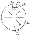
Rotation test section 11 for example comprises that the rotary encoder 24 that the anglec of rotation is carried out multistage detection realizes.Rotary encoder 24 comprises shadow shield 24a, reaches photoelectrical coupler 24b.Shadow shield 24a forms discoideus, has to the radial direction extension and separate certain intervals at circumferencial direction at its periphery a plurality of narrow slit 24c are set.Photoelectrical coupler 24b comprises: separate configuration at thickness direction both sides and shadow shield 24a corresponding to the periphery of shadow shield 24a, to the luminescent device 24d of shadow shield 24a irradiates light; And by the sensitive device 24e of narrow slit 24c from luminescent device 24d reception light.In the present embodiment, shadow shield 24a is to axial region 18 fixed installations.Rotary encoder 24 is by making the rotation of shadow shield 24a with axial region 18 rotation, by sensitive device 24c detect from luminescent device 24d send only by still blocking, passing through or interdict output pulse signal according to light.Count by umber of pulse, detect around the sense of rotation and the anglec of rotation of operating rod 2 around axis 20 to this pulse signal.
Detection to operating rod 2 sense of rotation of being undertaken by rotary encoder describes below.Fig. 4 is schematic representation is detected operating rod 2 sense of rotation by rotary encoder 24 the planimetric map that constitutes.Fig. 5 is the figure of expression from the output signal of rotary encoder 24.The output signal of Fig. 5 (a) expression the 1st photoelectrical coupler 24b1, the output signal of Fig. 5 (b) expression the 2nd photoelectrical coupler 24b2.Owing to detect the sense of rotation of operating rods 2, so the 1st photoelectrical coupler 24b1, and the 2nd photoelectrical coupler 24b2 are set on rotary encoder 24 by rotary encoder 24.These two photoelectrical coupler 24b1,24b2 are configured in the position of 90 ° of the phase phasic differences of its output signal.
The detection of operating rod 2 sense of rotation is undertaken by following.At first store the output signal level of 2 photoelectrical coupler 24b1,24b2 of present position, then along with the rotation of operating rod 2, which output signal level that detects photoelectrical coupler 24b1,24b2 changes earlier.Sense of rotation that like this can particular manipulation bar 2.Specifically, with reference to Fig. 5 (a), and Fig. 5 (b), the output signal level of supposing each photoelectrical coupler 24b1,24b2 of present position all is a low level.From the present position, when operating rod 2 during by the turning clockwise of Fig. 4, after the output signal level of the 2nd photoelectrical coupler 24b2 became high level, the output signal level of the 1st photoelectrical coupler 24b1 became high level.And from the present position, when operating rod 2 was pressed the inhour rotation of Fig. 4, after the output signal level of the 1st photoelectrical coupler 24b1 became high level, the output signal level of the 2nd photoelectrical coupler 24b2 became high level.At this moment, become high level than the output signal level of the 1st photoelectrical coupler 24b1 is first from low level, just can determine that operating rod 2 turns clockwise by the output signal level that detects the 2nd photoelectrical coupler 24b2.And become high level than the output signal level of the 2nd photoelectrical coupler 24b2 is first from low level by the output signal level that detects the 1st photoelectrical coupler 24b1, just can determine that operating rod 2 is rotated counterclockwise.Mobile test section 12 tilts, for example by inclination moving direction (arrow 22a~22h) upward realize from axis 20 a plurality of (being 8 in the present embodiment) limit switch 25a~25h by same radius distance configuration at operating rod 2, by pushing each limit switch 25a~25h, detect the inclination moving direction of operating rod 2.
Pressing detection portion 13 for example can realize by spring return formula limit switch 26.Can detect the push action of pushing direction 23 (Fig. 2's is right-hand) to operating rod 2 like this.
Like this, the guider 1 of present embodiment is owing to have the operating rod 2 of the action of can being rotated, inclination shift action and these 3 actions of push action, compare so only have the guider of 2 action operating rods with look-ahead technique, can distribute the operation of more navigation features operating rod 2.Thereby, compare with look-ahead technique, can reduce the switch number of operation board portion 4.In addition, the user confirms that the frequency of the position of the switch reduces when carrying out navigation feature, eliminated numerous and diverse.
Refer again to Fig. 1, the base map data that input is read by CD-ROM drive 8 in map depiction portion 9, and the user that detects by operation detection part 10 to the operational ton data of operating rod 2.Map depiction portion 9 is according to each data of being imported, makes map datum after the adjustment of adjusting to engineer's scale that the user wishes and position of rotation, and map datum after this adjustment that makes is exported to image RAM14.
Image RAM14 is a memory buffer, map datum after the adjustment that temporary transient storage is imported.Image transitions portion 15 reads out in data after the adjustment of being stored among the image RAM14, is converted into view data, exports to display 3.Display 3 shows according to the view data imported adjusts to the engineer's scale that the user wishes and the map of position of rotation.
Fig. 6 is illustrated in the figure that shows the state of road-map 28 in the display frame 31 of display 3.Fig. 7 is that expression is with the road-map 28 of Fig. 6 figure to the road-map 28a of 90 ° of counter rotations.Fig. 8 is the process flow diagram for 28 spinning movements of explanation road-map.The guider 1 of present embodiment can show road-map 28 in display frame 31.The road-map 28 of this demonstration can show around vertical axis rotation in display frame 31.The spinning movement of this road-map 28 can only be undertaken by the operation of operating rod 2.In display frame 31, can also show the vehicle icon of representing vehicle whereabouts and present position, the compass 41 that reaches expression road-map 28 upper positions.
The state that in display frame 31, shows road-map 28, by making operating rod 2 around axis 20 rotations, the road-map 28 that shows on can rotatingly displaying picture 31.At this moment, the sense of rotation of the operating rod of seeing from the user 2 and the sense of rotation of road-map 28 are consistent.That is, the user is by making operating rod 2 around axis 20 clockwises (arrow 21b) rotations, and the road-map 28 of display frame 31 is at the state that keeps with vehicle icon 40 relative position relations, sees from the user to turn clockwise.In addition, the user is by making operating rod 2 around axis 20 inhours (arrow 21a) rotation, and the road-map 28 of display frame 31 is seen the inhour rotation at the state of maintenance with vehicle icon 40 relative position relations from the user.Compass 41 itself does not rotate because of the spinning movement of operating rod 2, but needle 42 but is rotated with the rotation interlock of road-map 28.By such formation, owing to the relativeness between road-map 28 sense of rotation of operation that makes operating rod 2 and display frame 31 is clear and definite, so there is not the such imbalance sense of look-ahead technique.
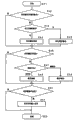
The spinning movement of road-map 28 is described below with reference to Fig. 8.On step S1, begin action, on step S2, judge by rotary encoder 24 whether detect rotation around the axis 20 of operating rod 2.When the rotation that detects around the axis 20 of operating rod 2, on step S3, judge its sense of rotation.When sense of rotation is inhour, on step S4, detect the rotation amount of operating rod 2.Then on step S5, road-map 28 inhour in display frame 31 is rotated the regulation rotation amount corresponding to the detection rotation amount, on step S8, and release.Be taken in sense of rotation when being clockwise at step S3, detect the rotation amount of operating rod 2 in step 36.Then on step S7, road-map 28 turns clockwise in display frame 31 corresponding to the regulation rotation amount of the rotation amount that is detected, release on step S8.If when not detecting operating rod 2 on the step S2 around axis 20 rotations, release on step S8.
In addition, the rotation amount of the road-map 28 of display frame 31 is corresponding to the rotation amount of operating rod 2.As mentioned above, the rotation amount of operating rod 2 detects by rotation test section 11.For example calculate by the umber of pulse of measuring rotary encoder 24.According to the rotation amount of this operating rod 2, the rotation amount of the road-map 28 of decision display frame 31.Illustrate in greater detail and be, the amount that multiply by the unit point of map depiction at the rotation amount that is detected by rotation test section 11 constitutes road-map 28 rotation amounts of display frame 31.This rotation amount of 28 rotations of road-map.Example state as shown in FIG. 6, when making operating rod 2 around axis 20 inhours (arrow 21a) half-twist, the road-map 28a of the counter-clockwise half-twist shown in Fig. 7 is presented in the display frame 31.
Fig. 9 is the road-map that expression is dwindled the road-map of Fig. 6.Figure 10 is the process flow diagram for explanation road-map engineer's scale change action.In the guider 1 of present embodiment, the engineer's scale of road-map shown in the display frame 31 28 can be changed in addition, the engineer's scale change of this road-map 28 can be only carried out by the operation of operating rod 2.
Below with reference to Figure 10, the change action of road 28 engineer's scales is described.On step S11, begin action, detecting operating rod 2 on step S12 pushes in axis 20 directions by limit switch 26, pass through rotary encoder 24 when axis 20 rotates at the fooled operating rod 2 that detects of step S13, on step S14, judge the sense of rotation of operating rod 2 around axis 20.When sense of rotation is the inhour rotation, on step S15, detect the rotation amount of operating rod 2.Then change ratio dipstick metering on step S16, the ormal weight that the road-map 28 of display frame 31 is dwindled corresponding to the rotation amount that is detected, tenth skill on step S19.When sense of rotation when being clockwise, on step S17, detect the rotation amount of operating rod 2.Then on step S18, the dipstick metering of change ratio makes the ormal weight of road-map 28 amplifications of display frame 31 corresponding to the rotation amount that is detected, tenth skill on step S19.On step S12, do not push to axis 20 directions if detect operating rod 2, do not detect operating rod 2 when axis 20 rotations, then tenth skill on step S19.
Yi Bian the state that shows road-map 28 in display frame 31 is by making operating rod 2 push to arrow 23 directions, Yi Bian around axis 20 rotations, can change the engineer's scale of road-map shown in the display frame 31 28.At this moment, Yi Bian the user is by pushing operating rod 2, Yi Bian around axis 20 clockwise (arrow 21b) rotation, the road-map 28 comparable shown states of display frame 31 amplify demonstration.In addition, Yi Bian the user is by pushing operating rod 2, Yi Bian around axis 20 inhours (arrow 21a) rotation, the road-map 28 comparable shown states of display frame 31 dwindle demonstration.The ratio dipstick metering of the road-map 28 of display frame 31 is corresponding to the rotation amount of operating rod 2.
Yi Bian example state as shown in FIG. 6 is when pushing operating rod 2, Yi Bian when axis 20 inhours (arrow 21a) were rotated, the road-map 28b that dwindles shown in Fig. 9 can be presented in the display frame 31.
Figure 11 is the figure that expression makes the road-map that the road-map of Fig. 6 roll to move.Figure 12 is the process flow diagram for explanation road-map scroll actions.In the guider 1 of present embodiment, road-map shown in the display frame 31 28 is rolled move, the rolling of can be only carrying out this road-map 28 by the operation of operating rod 2 is moved.
Below with reference to Figure 12, the scroll actions of road-map is described.On step S21, begin action, on step S22, detect the inclination of operating rod 2 moves by limit switch 25a~25h, on step S23, when detecting operating rod 2 by limit switch 26 when axis 20 directions are pushed, change rolling translational speed on step S24 is accelerated the rolling translational speed of road-map.In addition on step S23, if show by limit switch 26 and to detect operating rod 2 when axis 20 directions are pushed, then on step S25, it is constant that the rolling translational speed of road-map is kept the initial setting jogging speed.Then on step S26, the road-map 28 of display frame 31 rolls tenth skill on step S27 with the rolling translational speed that sets to the inclination moving direction of operating rod 2.On step S22, do not move if detect the inclination of operating rod 2, then tenth skill on step S27.
The state that shows road-map 28 in display frame 31 tilts to move by making operating rod 2, can make the road-map 28 of display frame 31 roll mobile.At this moment, the inclination moving direction of the operating rod of seeing from the user 2 and the rolling moving direction of road-map 28 are consistent.Promptly, when making operating rod 2, the user tilts when mobile to arrow 22b, see from the user road-map 28 of display frame 31 rolls upward and move, and when operating rod 2 is tilted when mobile to arrow 22f direction, it is mobile to see that from the user road-map 28 of display frame 31 rolls downwards.For example at the state of the road-map 28 of displayed map 6, when seeing operating rod 2 is tilted when mobile to left (arrow 22a) from the user, as shown in Figure 11, see in display frame 31 from the user to show the road-map 28c that rolls and move to left.
Make operating rod 2 tilt to move again, the road-map 28 of display frame 31 by operating rod 2 is pushed to arrow 23 directions, can change the rolling translational speed of road-map 28 in the moving process that rolls.At this, also can the rolling translational speed of road-map 28 be slowed down, but preferably accelerate the rolling translational speed by pushing operating rod 2.By accelerating the rolling translational speed, the road-map 28 of very fast demonstration destination locations improves usability.
In addition, the guider 1 of present embodiment has a plurality of navigation features.The figure of the display frame 31 when Figure 13 is each navigation feature of expression selection execution.Figure 14 is for the process flow diagram of cursor shift action is described.In display frame 31, can show indication carry out a plurality of icon 29a~29d of each navigation feature project, and for specifying specified devices such as the cursor 30 of carrying out this icon 29a~29d or pointer.In display frame 31, also show the exercise question of urgency navigation feature and the article 43 of project.The action of the cursor 30 of this demonstration can only be undertaken by the operation of operating rod 2.In Figure 13, two dot-and-dash lines just draw for convenience, do not show on actual displayed picture 31.
The shift action of cursor is described below with reference to Figure 14.On step S31, begin action, on step S32, move by the inclination of limit switch 25a~25h detection operating rod 2, on step S33, when detecting operating rod 2 by limit switch 26 when axis 20 directions are pushed, on step S34, change cursor moving speed, the translational speed of cursor 30 is accelerated.In addition, on step S33, if do not detect operating rod 2 when axis 20 directions are pushed by limit switch 26, then on step S35, it is constant that cursor moving speed is kept the initial setting jogging speed.Then on step S36, the cursor moving speed of cursor 30 to set of display frame 31 moves tenth skill on step S37 to the vergence direction of operating rod 2.On step S37, when the inclination that does not detect operating rod 2 is mobile, tenth skill on step 37.
The state of display highlighting 30 in display frame 31 tilts to move by making operating rod 2, cursor 30 that can mobile display frame 31.At this moment, see that from the user inclination moving direction of manipulation mark 2 and the moving direction of cursor 30 are consistent.Promptly operating rod 2 is tilted when mobile to arrow 22b direction as the user, the cursor of display frame 31 30 is seen from the user and is moved upward.In the example example as shown in Figure 13, the icon 29a of cursor 30 above icon 29b moves.In addition, tilt when mobile to arrow 22f direction when the user makes operating rod 2, the cursor 30 of display frame 31 is seen downwards from the user and to be moved.For example, in the example shown in Figure 13, cursor 30 moves to the icon 29c of icon 29b below.
Make operating rod 2 tilt to move again, the cursor 30 of display frame 31 by operating rod 2 is pushed to arrow 23 directions, can change the translational speed of cursor 30 in moving process.By pushing operating rod 2 translational speed of cursor 30 is slowed down at this, but preferably accelerate translational speed.Like this,, can make the icon of the project of the very fast arrival purpose of cursor 30, improve usability by accelerating the translational speed of cursor 30.
In addition, in guider 1 of the present invention, the map code (login trade mark) of the positional information that has telephone number, postcode, latitude and the longitude information according to the destination and the position data of particular place is encoded arrives the exploration function of the optimal path of destination.Numerical datas such as these telephone numbers, postcode, latitude and longitude information and map code can only be imported by operating the above-mentioned control lever 2 that carries out 3 actions.Display frame 31 when Figure 15 is the input of expression telephone number.Figure 16 is for the process flow diagram of telephone number input action is described.
In display frame 31, for example can show corresponding to everybody a plurality of 32a~32j of telephone number, and expression can input state cursor 33.In display frame 31, but the display reminding input is corresponding to the article 44 of the numerical data of item selected in the display frame 31 of Figure 13.In Figure 15, three dot-and-dash lines just are provided with for convenience, do not show in the display frame 31 of reality.
Below with reference to Figure 16, the input action of telephone number is described.On step S41, begin action, on step S42, when the inclination that detects operating rod 2 by limit switch 25a~25h is mobile, on step S43, judge it is that to the left and right which direction tilts to move.To be left move to the position that is equivalent to exist now left lateral of, the cursor 33 of then display frame 31 on step S44 if the inclination of operating rod 2 is moved.And the inclination of operating rod 2 to move be right, then on step S45, the cursor 33 of display frame 31 moves to the right lateral of position that is equivalent to exist now.
On step S42, when the inclination that does not detect operating rod 2 is mobile, perhaps after cursor 33 moves on step S44, the S45, on step S46, judge whether to have detected the rotation of operating rod 2 around axis 20 by rotary encoder 24.When detecting the rotation of operating rod 2, on step S47, judge the sense of rotation of operating rod 2.When sense of rotation is inhour, on step S48, deduct shown numeral on the piece 32 that has cursor 33.And when sense of rotation is inhour,, add shown numeral on the piece 32 that has cursor 33 at step S49.
When on step S46, not detecting the rotation of operating rod 42, perhaps the enterprising line number word of step S48, S49 subtract each other or addition after, be taken at step S50 and detect operating rod 2 when axis 20 directions are pushed by limit switch, on step S51, determine the input of telephone number, tenth skill on step 52.
Like this, under the state that shows each piece 32 and cursor 33,, the numeral on the cursor 33 is increased and decreased between 0~9 by making operating rod 2 around axis 20 rotations.At this moment whenever the user makes operating rod 2 when axis 20 clockwise (arrow 21b) rotates 36 °, be presented to add 1 numeral on the shown numeral.And whenever the user makes operating rod 2 when axis 20 inhours (arrow 21a) are rotated 36 °, be presented to subtract 1 numeral on the shown numeral.When the numeral on cursor 33 is " 9 ", when operating rod 2 when axis 20 turns clockwise, do not carry out on shown numeral, adding 1 processing, show " 9 " in the same old way or show " 0 ".When the numeral on cursor 33 is " 0 ",, do not carry out subtracting 1 processing from shown numeral, show " 0 " in the same old way or show " 9 " when operating rod 2 during around the rotation of axis 20 inhour.
, tilt to move during telephone number in input in addition, can carry out the moving of position of cursor 33 by making operating rod 2.At this moment, the moving direction of the inclination moving direction of operating rod 2 and cursor 33 is consistent.For example see operating rod 2 is tilted when mobile to right (arrow 22h direction), see that from the user cursor 33 piece 32f to the right moves from the user.And from the user see make operating rod 2 left direction (arrow 22d direction) tilt when mobile, see that from the user cursor 33 piece 32d to the left moves.When cursor 33 is present among the piece 32a of left end, if operating rod 2 more left direction tilt when mobile, then cursor 33 persists among the piece 32a, perhaps moves to piece 32j.And when cursor 33 was present among the piece 32j, if operating rod 2 tilts when mobile to right again, then cursor 33 persisted among the piece 32j, perhaps moves to piece 32a.
When the inclination of above-mentioned operating rod 2 being moved and rotary manipulation makes up, during the input of terminating telephone number,, determine the telephone number of being imported by operating rod 2 is pushed to pushing direction 23.Like this, when determining telephone number, can explore the path of the destination of this telephone number.
As mentioned above, owing to only just carrying out everybody digital alter operation of numerical data of telephone number, postcode, latitude and longitude information and map code etc., the moving definite operation operating, reach the numerical data of input of displacement of cursor 33, so can improve operating speed by the operation of operating rod 2.Also owing to the time do not need the pressing operation of look-ahead technique in everybody numeral input, thus the wrong mobile operating rod that tilts in the numeral input can be prevented, and make cursor carry out the moving operating mistake of displacement.
The present invention only otherwise break away from its spirit or principal character can be with other various forms enforcement.Thereby, the only individual in all respects example of above-mentioned first draft example, scope of the present invention is the scope of claim, is not subjected to any restriction in the instructions text.
In addition, distortion and the change that belongs in the impartial scope of claim all belongs in the scope of the invention.
The possibility of utilizing on the industry
According to the present invention, since have to predetermined a plurality of directions tilt mobile, around the rotation of axis, and press the control stick of 3 actions to axis direction, so the operation to this control stick can distribute multiple navigation feature, compare with look-ahead technique, can reduce the number of switches of remote controller and operation board section.
In addition, according to the present invention, because by control stick is rotated around axis, map shown on display unit rotates, so can eliminate the inharmonious sense of map rotary manipulation.
In addition, according to the present invention, owing on control stick, also can distribute the operation that changes map scale, thus need not contact control stick other operating equipments in addition, such as switch etc.
In addition, according to the present invention since only with the operation of control stick just can change map rolling, reach the rolling speed of map, so can improve operability.
In addition, according to the present invention, the user only just can move the specified device of specifying the project that represents each navigation feature with the operation of control stick, and can change the translational speed of specified device. Thereby can improve operability.
In addition, according to the present invention, owing to can carry out by 1 control stick move operation, and definite operation of numerical data of alter operation, the position of each bit digital of numerical data such as telephone number, postcode, latitude and longitude information or positional information, so can improve operability, particularly input speed. In addition, owing to when the input of each bit digital, do not need pressing operation, so can prevent wrong inclination mobile operating bar in the input of numeral, make cursor carry out the moving operating mistake of displacement.
Claims (6)
1. guider, can be on display unit displayed map, it is characterized in that, comprising:
Operating rod is indicated the above-mentioned map of roll display by making this operating rod tilt to move,
Above-mentioned operating rod can carry out engineer's scale change input, and described engineer's scale change input is according to the sense of rotation of the state that is pressed rotary manipulation down, indicates the engineer's scale of above-mentioned map to become greatly or diminishes.
2. guider, can be on display unit displayed map, it is characterized in that, comprising:
Operating rod is indicated the above-mentioned map of roll display by making this operating rod tilt to move;
Control module, this control module has the rotation test section that is used to detect the rotary manipulation of above-mentioned operating rod under the state of being pressed, under the situation of the rotary manipulation that detects above-mentioned operating rod by above-mentioned rotation test section, according to the sense of rotation of rotary manipulation, become the engineer's scale of big or the above-mentioned map that diminishes.
3. guider according to claim 1 and 2 is characterized in that:
To conterclockwise rotary manipulation, make the engineer's scale of above-mentioned map become big according to above-mentioned operating rod; To counterclockwise rotary manipulation, the engineer's scale of above-mentioned map is diminished according to above-mentioned operating rod.
4. guider according to claim 1 and 2 is characterized in that:
According to the rotation amount of above-mentioned rotary manipulation, determine the engineer's scale size of above-mentioned map.
5. guider according to claim 1 is characterized in that:
Tilt when mobile at the aforesaid operations bar, can make above-mentioned map continue to carry out rolling to prescribed direction.
6. guider according to claim 2 is characterized in that:
The rotation starting position of above-mentioned rotation test section is not fixed, and detects rotation according to the rotation change amount.
Applications Claiming Priority (2)
| Application Number | Priority Date | Filing Date | Title |
|---|---|---|---|
| JP2001058819A JP3814154B2 (en) | 2001-03-02 | 2001-03-02 | Navigation device |
| JP058819/2001 | 2001-03-02 |
Related Parent Applications (1)
| Application Number | Title | Priority Date | Filing Date |
|---|---|---|---|
| CNB028005015A Division CN1304820C (en) | 2001-03-02 | 2002-02-28 | Navigation device |
Publications (2)
| Publication Number | Publication Date |
|---|---|
| CN1865860A CN1865860A (en) | 2006-11-22 |
| CN1865860B true CN1865860B (en) | 2010-05-26 |
Family
ID=18918484
Family Applications (3)
| Application Number | Title | Priority Date | Filing Date |
|---|---|---|---|
| CN2006100930307A Expired - Fee Related CN1865860B (en) | 2001-03-02 | 2002-02-28 | Navigation apparatus |
| CNB2006100930345A Expired - Fee Related CN100549624C (en) | 2001-03-02 | 2002-02-28 | Guider |
| CNB028005015A Expired - Fee Related CN1304820C (en) | 2001-03-02 | 2002-02-28 | Navigation device |
Family Applications After (2)
| Application Number | Title | Priority Date | Filing Date |
|---|---|---|---|
| CNB2006100930345A Expired - Fee Related CN100549624C (en) | 2001-03-02 | 2002-02-28 | Guider |
| CNB028005015A Expired - Fee Related CN1304820C (en) | 2001-03-02 | 2002-02-28 | Navigation device |
Country Status (7)
| Country | Link |
|---|---|
| US (2) | US6862520B2 (en) |
| EP (2) | EP1696211B1 (en) |
| JP (1) | JP3814154B2 (en) |
| KR (2) | KR100554476B1 (en) |
| CN (3) | CN1865860B (en) |
| DE (1) | DE60231685D1 (en) |
| WO (1) | WO2002070991A1 (en) |
Families Citing this family (30)
| Publication number | Priority date | Publication date | Assignee | Title |
|---|---|---|---|---|
| CN100486782C (en) * | 2002-03-09 | 2009-05-13 | 燕山大学 | Spatially symmetrical and parallel robot mechanism with dual parallel lines and 3,4 and 5 freedoms |
| JP2003269984A (en) * | 2002-03-19 | 2003-09-25 | Honda Motor Co Ltd | Navigation device |
| US6631322B1 (en) * | 2002-12-06 | 2003-10-07 | General Electric Co. | Method and apparatus for vehicle management |
| JP4159420B2 (en) * | 2003-07-10 | 2008-10-01 | アルパイン株式会社 | Map scroll control device and navigation device |
| JP4214025B2 (en) | 2003-09-04 | 2009-01-28 | 株式会社東海理化電機製作所 | Monitor display control device |
| JP4158105B2 (en) | 2003-09-25 | 2008-10-01 | ソニー株式会社 | In-vehicle device and method for controlling in-vehicle device |
| JP2005165045A (en) * | 2003-12-03 | 2005-06-23 | Denso Corp | Electronic apparatus with map display function and program |
| US7880247B2 (en) * | 2003-12-29 | 2011-02-01 | Vladimir Vaganov | Semiconductor input control device |
| US7772657B2 (en) * | 2004-12-28 | 2010-08-10 | Vladimir Vaganov | Three-dimensional force input control device and fabrication |
| US7554167B2 (en) | 2003-12-29 | 2009-06-30 | Vladimir Vaganov | Three-dimensional analog input control device |
| US8350345B2 (en) | 2003-12-29 | 2013-01-08 | Vladimir Vaganov | Three-dimensional input control device |
| US9034666B2 (en) | 2003-12-29 | 2015-05-19 | Vladimir Vaganov | Method of testing of MEMS devices on a wafer level |
| KR100762565B1 (en) | 2005-01-14 | 2007-10-01 | 엘지전자 주식회사 | The jog dial typed menu searching method and apparatus thereof |
| US7461345B2 (en) * | 2005-03-11 | 2008-12-02 | Adobe Systems Incorporated | System and method for displaying information using a compass |
| DK1864204T3 (en) * | 2005-03-30 | 2012-10-22 | Gcoder Systems Ab | Control device |
| WO2007035988A1 (en) * | 2005-09-27 | 2007-04-05 | Spatial Freedom Holdings Pty Ltd | An interface for computer controllers |
| US7707516B2 (en) * | 2006-05-26 | 2010-04-27 | Google Inc. | Embedded navigation interface |
| EP1959238B1 (en) * | 2007-02-13 | 2018-05-23 | Harman Becker Automotive Systems GmbH | Method for inputting a destination in a navigation unit and nagivation system therefor |
| JP5102684B2 (en) * | 2008-04-09 | 2012-12-19 | 株式会社オートネットワーク技術研究所 | Operating device |
| JP2010115312A (en) * | 2008-11-12 | 2010-05-27 | Fujishoji Co Ltd | Pinball game machine |
| US9569066B2 (en) | 2011-10-03 | 2017-02-14 | Google Inc. | Interface for navigating imagery |
| CN102865871B (en) * | 2012-09-07 | 2015-08-05 | 广东好帮手电子科技股份有限公司 | A kind ofly realize the method for navigation map convergent-divergent, system and automobile based on code switch |
| USD757027S1 (en) * | 2013-03-15 | 2016-05-24 | Google Inc. | Display screen with graphical user interface |
| US10824328B2 (en) * | 2013-05-10 | 2020-11-03 | International Business Machines Corporation | Optimized non-grid based navigation |
| KR101657658B1 (en) * | 2015-08-13 | 2016-09-19 | 현대자동차주식회사 | Input apparatus, vehicle comprising the same and control method for the vehicle |
| JP2017059072A (en) * | 2015-09-18 | 2017-03-23 | 株式会社Jvcケンウッド | Display control device, display control method, and display control program |
| US10214933B2 (en) | 2017-05-11 | 2019-02-26 | Hayward Industries, Inc. | Pool cleaner power supply |
| CN107272926B (en) * | 2017-07-03 | 2020-11-03 | 京东方科技集团股份有限公司 | Touch panel controller, control information acquisition method and touch display device |
| CN110779541B (en) * | 2019-04-10 | 2021-11-23 | 北京嘀嘀无限科技发展有限公司 | Display method and system of steering arrow |
| KR20240019107A (en) * | 2021-06-08 | 2024-02-14 | 지에이치에스피, 아이엔씨. | User interface using a dial controller, including a rotary dial that can be manipulated along or around three axes |
Citations (4)
| Publication number | Priority date | Publication date | Assignee | Title |
|---|---|---|---|---|
| CN1127396A (en) * | 1995-01-20 | 1996-07-24 | 三菱电机株式会社 | Mobile navigation system |
| EP0841537A2 (en) * | 1996-11-07 | 1998-05-13 | Xanavi Informatics Corporation | Method and apparatus for displaying a navigation map |
| US5945927A (en) * | 1993-12-27 | 1999-08-31 | Nissan Motor Co., Ltd. | Apparatus and method for navigating vehicle to destination using display unit |
| CN1285517A (en) * | 1999-08-24 | 2001-02-28 | 日本电气株式会社 | Global positioning system terminal, positioning measurment system and map-indication method |
Family Cites Families (32)
| Publication number | Priority date | Publication date | Assignee | Title |
|---|---|---|---|---|
| US3688312A (en) * | 1970-01-07 | 1972-08-29 | Walter R Gustafson | Integrated display system for combat aircraft |
| JPH05241502A (en) * | 1992-03-02 | 1993-09-21 | Fujitsu Ten Ltd | Scrolling control method for display image in image display device |
| JPH07141598A (en) | 1993-11-19 | 1995-06-02 | Nissan Motor Co Ltd | Device for displaying for vehicle |
| JP3360403B2 (en) | 1994-03-31 | 2002-12-24 | 日産自動車株式会社 | Route guidance device for vehicles |
| JPH08128839A (en) | 1994-10-31 | 1996-05-21 | Sumitomo Electric Ind Ltd | Map display in navigation device |
| JP3401966B2 (en) | 1994-12-20 | 2003-04-28 | 日産自動車株式会社 | Route guidance device for vehicles |
| JP3235447B2 (en) | 1996-02-07 | 2001-12-04 | トヨタ自動車株式会社 | Image scaling adjustment device |
| EP0836167B1 (en) * | 1996-08-21 | 2006-05-17 | Aisin Aw Co., Ltd. | Device for displaying map and method |
| JPH10122876A (en) | 1996-10-17 | 1998-05-15 | Sumitomo Electric Ind Ltd | Navigator |
| JPH10197263A (en) | 1997-01-10 | 1998-07-31 | Sumitomo Electric Ind Ltd | Navigation display |
| JPH10214128A (en) | 1997-01-30 | 1998-08-11 | Yazaki Corp | Joy stick type multifuctional controller |
| JPH10268759A (en) * | 1997-03-21 | 1998-10-09 | Sony Corp | Electronic map display device |
| JPH10301485A (en) | 1997-05-01 | 1998-11-13 | Pioneer Electron Corp | Input-output controller in navigation system |
| EP0896315B1 (en) * | 1997-08-08 | 2005-06-22 | Alpine Electronics, Inc. | Display unit for navigation apparatus |
| JP3313632B2 (en) | 1997-11-18 | 2002-08-12 | 松下電器産業株式会社 | Navigation device operating device |
| JP3861273B2 (en) | 1997-12-18 | 2006-12-20 | ソニー株式会社 | Portable information terminal device and information display control method for portable information terminal device |
| JP3797405B2 (en) | 1998-03-23 | 2006-07-19 | アイシン・エィ・ダブリュ株式会社 | Vehicle navigation device and storage medium |
| JPH11304503A (en) | 1998-04-17 | 1999-11-05 | Matsushita Electric Ind Co Ltd | Information display device |
| JP3874924B2 (en) | 1998-04-21 | 2007-01-31 | アルパイン株式会社 | Car navigation system |
| US6196845B1 (en) * | 1998-06-29 | 2001-03-06 | Harold R. Streid | System and method for stimulating night vision goggles |
| JP4059408B2 (en) | 1998-08-21 | 2008-03-12 | 株式会社バンダイナムコゲームス | GAME DEVICE AND INFORMATION STORAGE MEDIUM |
| JP3559951B2 (en) | 1998-12-18 | 2004-09-02 | 株式会社ケンウッド | Navigation device |
| JP4134423B2 (en) | 1999-02-24 | 2008-08-20 | アイシン・エィ・ダブリュ株式会社 | Vehicle information display device and recording medium of the device |
| JP2000314633A (en) | 1999-04-28 | 2000-11-14 | To Be Life Institute Kk | Navigation system |
| JP2000347792A (en) | 1999-06-02 | 2000-12-15 | Sankyo Seiki Mfg Co Ltd | Device for inputting personal identification number |
| JP2000346669A (en) | 1999-06-09 | 2000-12-15 | Equos Research Co Ltd | Method and apparatus for retrieving telephone number, its navigator |
| DE19929587A1 (en) | 1999-06-29 | 2001-01-04 | Volkswagen Ag | Display device, in particular for a motor vehicle |
| JP2002081942A (en) | 2000-09-06 | 2002-03-22 | Kenwood Corp | Navigator |
| JP3982184B2 (en) | 2001-02-16 | 2007-09-26 | 三菱自動車工業株式会社 | Navigation device |
| JP4260383B2 (en) | 2001-07-06 | 2009-04-30 | アルパイン株式会社 | In-vehicle display device |
| US6640185B2 (en) * | 2001-07-21 | 2003-10-28 | Alpine Electronics, Inc. | Display method and apparatus for navigation system |
| JP3764473B2 (en) | 2005-04-21 | 2006-04-05 | 富士通テン株式会社 | Map display device |
-
2001
- 2001-03-02 JP JP2001058819A patent/JP3814154B2/en not_active Expired - Fee Related
-
2002
- 2002-02-28 US US10/275,045 patent/US6862520B2/en not_active Ceased
- 2002-02-28 US US11/372,451 patent/USRE42806E1/en not_active Expired - Fee Related
- 2002-02-28 EP EP06011657A patent/EP1696211B1/en not_active Expired - Fee Related
- 2002-02-28 KR KR1020027014567A patent/KR100554476B1/en not_active IP Right Cessation
- 2002-02-28 EP EP02701617A patent/EP1293756B1/en not_active Expired - Lifetime
- 2002-02-28 WO PCT/JP2002/001829 patent/WO2002070991A1/en not_active Application Discontinuation
- 2002-02-28 CN CN2006100930307A patent/CN1865860B/en not_active Expired - Fee Related
- 2002-02-28 CN CNB2006100930345A patent/CN100549624C/en not_active Expired - Fee Related
- 2002-02-28 KR KR1020057024529A patent/KR100597576B1/en not_active IP Right Cessation
- 2002-02-28 CN CNB028005015A patent/CN1304820C/en not_active Expired - Fee Related
- 2002-02-28 DE DE60231685T patent/DE60231685D1/en not_active Expired - Lifetime
Patent Citations (4)
| Publication number | Priority date | Publication date | Assignee | Title |
|---|---|---|---|---|
| US5945927A (en) * | 1993-12-27 | 1999-08-31 | Nissan Motor Co., Ltd. | Apparatus and method for navigating vehicle to destination using display unit |
| CN1127396A (en) * | 1995-01-20 | 1996-07-24 | 三菱电机株式会社 | Mobile navigation system |
| EP0841537A2 (en) * | 1996-11-07 | 1998-05-13 | Xanavi Informatics Corporation | Method and apparatus for displaying a navigation map |
| CN1285517A (en) * | 1999-08-24 | 2001-02-28 | 日本电气株式会社 | Global positioning system terminal, positioning measurment system and map-indication method |
Also Published As
| Publication number | Publication date |
|---|---|
| EP1293756A1 (en) | 2003-03-19 |
| US20030105576A1 (en) | 2003-06-05 |
| CN1865860A (en) | 2006-11-22 |
| EP1696211A1 (en) | 2006-08-30 |
| KR100554476B1 (en) | 2006-03-03 |
| EP1293756A4 (en) | 2006-08-23 |
| EP1293756B1 (en) | 2009-03-25 |
| USRE42806E1 (en) | 2011-10-04 |
| KR20060006106A (en) | 2006-01-18 |
| JP2002257558A (en) | 2002-09-11 |
| CN1457421A (en) | 2003-11-19 |
| CN1304820C (en) | 2007-03-14 |
| KR20030007561A (en) | 2003-01-23 |
| KR100597576B1 (en) | 2006-07-10 |
| US6862520B2 (en) | 2005-03-01 |
| JP3814154B2 (en) | 2006-08-23 |
| CN1865861A (en) | 2006-11-22 |
| CN100549624C (en) | 2009-10-14 |
| EP1696211B1 (en) | 2012-04-11 |
| WO2002070991A1 (en) | 2002-09-12 |
| DE60231685D1 (en) | 2009-05-07 |
Similar Documents
| Publication | Publication Date | Title |
|---|---|---|
| CN1865860B (en) | Navigation apparatus | |
| US5289572A (en) | Electronic map combined with user service information | |
| EP1887454A2 (en) | Remote input device and electronic apparatus using the same | |
| JP5259898B2 (en) | Display device and display processing method | |
| CN101589354A (en) | Orientation-sensitive signal output | |
| JP4609242B2 (en) | Operation control device | |
| US20070032944A1 (en) | Display device for car navigation system | |
| CN101852618A (en) | Guider | |
| CN101387940A (en) | Handheld electronic device with motion-controlled display | |
| CN102472626B (en) | Map display device | |
| CN101393509A (en) | Method of displaying planar image | |
| CN101726293A (en) | Navigation apparatus | |
| JP3559951B2 (en) | Navigation device | |
| CN101593427A (en) | The method that number plate restriction corresponding intrument and number plate restriction corresponding intrument are used | |
| JPH05313580A (en) | Navigation device and data input conrol method for the device | |
| JPH05346923A (en) | Display and input device | |
| CN102566898A (en) | Control device, control method of control device, and computer program | |
| JP2004271439A (en) | Operation system and cursor controller unit | |
| US20070195065A1 (en) | Jog-dial assisted character selection | |
| JP2000241170A (en) | Scrolling method and navigation device | |
| CN101813487A (en) | Navigation device and display method thereof | |
| JP3953729B2 (en) | Navigation device | |
| JP3764473B2 (en) | Map display device | |
| JPH01213685A (en) | Map scroll plotter | |
| JP2004077496A (en) | Navigation system |
Legal Events
| Date | Code | Title | Description |
|---|---|---|---|
| C06 | Publication | ||
| PB01 | Publication | ||
| C10 | Entry into substantive examination | ||
| SE01 | Entry into force of request for substantive examination | ||
| C14 | Grant of patent or utility model | ||
| GR01 | Patent grant | ||
| CF01 | Termination of patent right due to non-payment of annual fee |
Granted publication date: 20100526 Termination date: 20160228 |
|
| CF01 | Termination of patent right due to non-payment of annual fee |