DE102007030700A1 - Measuring system for a medium flowing in a process line - Google Patents
Measuring system for a medium flowing in a process line Download PDFInfo
- Publication number
- DE102007030700A1 DE102007030700A1 DE102007030700A DE102007030700A DE102007030700A1 DE 102007030700 A1 DE102007030700 A1 DE 102007030700A1 DE 102007030700 A DE102007030700 A DE 102007030700A DE 102007030700 A DE102007030700 A DE 102007030700A DE 102007030700 A1 DE102007030700 A1 DE 102007030700A1
- Authority
- DE
- Germany
- Prior art keywords
- measuring
- measuring system
- medium
- density
- pressure
- Prior art date
- Legal status (The legal status is an assumption and is not a legal conclusion. Google has not performed a legal analysis and makes no representation as to the accuracy of the status listed.)
- Withdrawn
Links
Classifications
-
- G—PHYSICS
- G01—MEASURING; TESTING
- G01N—INVESTIGATING OR ANALYSING MATERIALS BY DETERMINING THEIR CHEMICAL OR PHYSICAL PROPERTIES
- G01N9/00—Investigating density or specific gravity of materials; Analysing materials by determining density or specific gravity
- G01N9/26—Investigating density or specific gravity of materials; Analysing materials by determining density or specific gravity by measuring pressure differences
- G01N9/266—Investigating density or specific gravity of materials; Analysing materials by determining density or specific gravity by measuring pressure differences for determining gas density
-
- G—PHYSICS
- G01—MEASURING; TESTING
- G01F—MEASURING VOLUME, VOLUME FLOW, MASS FLOW OR LIQUID LEVEL; METERING BY VOLUME
- G01F1/00—Measuring the volume flow or mass flow of fluid or fluent solid material wherein the fluid passes through a meter in a continuous flow
- G01F1/05—Measuring the volume flow or mass flow of fluid or fluent solid material wherein the fluid passes through a meter in a continuous flow by using mechanical effects
- G01F1/20—Measuring the volume flow or mass flow of fluid or fluent solid material wherein the fluid passes through a meter in a continuous flow by using mechanical effects by detection of dynamic effects of the flow
- G01F1/32—Measuring the volume flow or mass flow of fluid or fluent solid material wherein the fluid passes through a meter in a continuous flow by using mechanical effects by detection of dynamic effects of the flow using swirl flowmeters
- G01F1/325—Means for detecting quantities used as proxy variables for swirl
- G01F1/3287—Means for detecting quantities used as proxy variables for swirl circuits therefor
-
- G—PHYSICS
- G01—MEASURING; TESTING
- G01F—MEASURING VOLUME, VOLUME FLOW, MASS FLOW OR LIQUID LEVEL; METERING BY VOLUME
- G01F1/00—Measuring the volume flow or mass flow of fluid or fluent solid material wherein the fluid passes through a meter in a continuous flow
- G01F1/76—Devices for measuring mass flow of a fluid or a fluent solid material
- G01F1/86—Indirect mass flowmeters, e.g. measuring volume flow and density, temperature or pressure
- G01F1/88—Indirect mass flowmeters, e.g. measuring volume flow and density, temperature or pressure with differential-pressure measurement to determine the volume flow
-
- G—PHYSICS
- G01—MEASURING; TESTING
- G01N—INVESTIGATING OR ANALYSING MATERIALS BY DETERMINING THEIR CHEMICAL OR PHYSICAL PROPERTIES
- G01N9/00—Investigating density or specific gravity of materials; Analysing materials by determining density or specific gravity
- G01N9/32—Investigating density or specific gravity of materials; Analysing materials by determining density or specific gravity by using flow properties of fluids, e.g. flow through tubes or apertures
Abstract
Das Meßsystem dient zum Messen einer Dichte eines in einer Prozeßleitung strömenden, entlang einer gedachten Strömungsachse des Meßsystems hinsichtlich eines thermodynamischen Zustandes veränderlichen, insbesondere zumindest anteilig kompressiblen Mediums. Das Meßsystem umfaßt dafür wenigstens einen an einer Temperaturmeßstelle platzierten, primär auf eine lokale Temperatur, theta, von vorbeiströmendem Medium reagierenden Temperatursensor, der wenigstens ein von der lokalen Temperatur des zu messenden Mediums beeinflußtes Temperaturmeßsignal liefert, wenigstens einen an einer Druckmeßstelle platzierten, primär auf einen lokalen, insbesondere statischen Druck, p, von vorbei strömendem Medium reagierenden Drucksensor, der wenigstens ein vom lokalen Druck, p, im zu messenden Medium beeinflußtes Druckmeßsignal liefert, sowie eine mit wenigstens dem Temperatursensor und dem Drucksensor jeweils zumindest zeitweise kommunizierende Meßelektronik. Die Meßelektronik ermittelt unter Verwendung sowohl des Temperaturmeßsignals als auch zumindest des Druckmeßsignals einen provisorischen Dichte-Meßwert, der eine Dichte repräsentiert, die das strömende Medium an einer insbesondere von der Druckmeßstelle und/oder der Temeperaturmeßstelle entlang der Strömungsachse vorgebbar beabstandeten, virtuellen Dichtemeßstelle lediglich scheinbar aufweist. Des weiteren erzeugt die Meßelektronik unter Verwendung des provisorischen Dichte-Meßwerts sowie wenigstens eines sowohl von einer ...The measuring system is used to measure a density of flowing in a process line, along an imaginary flow axis of the measuring system with respect to a thermodynamic state variable, in particular at least partially compressible medium. For this, the measuring system comprises at least one temperature sensor placed at a temperature measuring point and reacting primarily to a local temperature, theta, by a temperature measuring signal influenced by the local temperature of the medium to be measured, at least one placed at a pressure measuring point, primarily one local, in particular static pressure, p, by past flowing medium responsive pressure sensor which supplies at least one of the local pressure, p, in the medium to be measured influenced pressure, and at least at least temporarily with at least the temperature sensor and the pressure sensor at least temporarily communicating measuring electronics. Using both the temperature measurement signal and at least the pressure measurement signal, the measurement electronics determine a provisional density measurement which represents a density which the media only apparently has at a virtual density measurement location that is predeterminably spaced from the pressure measurement location and / or the temperature measurement location , Furthermore, the measuring electronics generates using the provisional density measured value as well as at least one of both a ...
Description
Die Erfindung betrifft ein Meßsystem zum Messen einer Dichte eines in einer Prozeßleitung strömenden, entlang einer gedachten Strömungsachse des Meßsystems hinsichtlich eines thermodynamischen Zustandes veränderlichen, insb. zumindest anteilig kompressiblen, Mediums mittels eines Temperatursensors, eines Drucksensors sowie einer mit Temperatur- und Drucksensor jeweils zumindest zeitweise kommunizierende Meßelektronik, die zumindest zeitweise wenigstens einen Dichte-Meßwert erzeugt, der eine lokale Dichte des strömenden Mediums möglichst genau repräsentiert.The The invention relates to a measuring system for measuring a density one in a process line flowing, along an imaginary flow axis of the measuring system variable with respect to a thermodynamic state, esp. At least proportionately compressible, medium by means of a temperature sensor, a Pressure sensor and one with temperature and pressure sensor respectively at least temporarily communicating measuring electronics, the at least temporarily produces at least one density reading, the local density of the flowing medium as possible exactly represented.
Zur Erfassung von prozeßbeschreibenden Meßgrößen strömender Medien, wie der thermodynamischen Zustandsgröße Dichte oder davon abgeleiteten Meßgrößen, und zur Erzeugung von die selbige Meßgröße entsprechend repräsentierenden Meßwerte werden in der industriellen Prozeß-Meßtechnik, insb. auch im Zusammenhang mit der Automatisierung chemischer oder verfahrenstechnischer Prozesse, prozeßnah installierte Meßsysteme verwendet, die oftmals mittels zweier oder mehrerer miteinander kommunizierenden, jeweils direkt an oder in einer von Medium durchströmten Prozeßleitung angebrachten eigenständiger Feldmeßgeräten gebildet sind. Die zu erfassenden Meßgrößen können neben der Dichte beispielsweise auch andere, insb. sensorisch erfaßbar und insoweit direkt meßbare, thermodynamischen Zustandsgrößen wie z. B. Druck oder Temperatur, direkt oder indirekt meßbare Strömungsparameter, wie z. B. eine Strömungsgeschwindigkeit, ein Volumendurchfluß oder ein Massendurchfluß, oder andere komplexe Transportgrößen, wie z. B. ein Wärmefluß, wie auch weitere mediumsspezifische Meßgrößen, wie z. B. eine Viskosität, von einem zumindest anteilig flüssigen, pulver-, oder gasförmigen Medium sein, das in einer, beispielsweise als Rohrleitung ausgebildeten, Prozeßleitung entsprechend geführt wird.to Acquisition of process-describing measured quantities flowing media, such as the thermodynamic state quantity Density or derived quantities, and for generating the selbige measured variable correspondingly representative measured values in the industrial process measuring technique, esp. also in connection with the automation of chemical or process engineering Processes, process-installed measuring systems used, often using two or more communicating, each directly on or in a medium flowed through Process line attached independent field meters are formed. The measured quantities to be recorded In addition to the density, for example, others, esp. sensory detectable and in this respect directly measurable, thermodynamic state variables such. B. pressure or Temperature, directly or indirectly measurable flow parameters, such as As a flow rate, a volume flow or a mass flow, or other complex transport sizes, such as As a heat flow, as well as other medium-specific Measured variables, such as. A viscosity, from an at least partly liquid, powdery or gaseous medium be in one, for example, designed as a pipeline, Process line is performed accordingly.
Besonders
für die indirekte – im folgenden daher auch als
virtuell bezeichnete – Messung der Dichte, basierend auf
mittels entsprechender Sensoren generierten Druck- und Temperatur-Meßsignalen,
wie auch allfällig davon abgeleiten Meßgrößen,
beispielsweise dem Massendurchfluß oder dem Volumendurchfluß,
haben sich zahlreiche industrielle Standards etabliert, die eine
weitgehend genormte, insoweit vergleichbare Berechnung empfehlen,
insb. auch unter Verwendung direkt erfaßter und insoweit
real gemessener Temperaturen und/oder Drücke, und die je
nach Anwendungsbereich und Medium ihre Anwendung finden. Als Beispiele für
solche Standards seien exemplarisch der Industrie-Standard
Oftmals dient die Ermittlung der Dichte weiterführend auch dazu, einen eher direkt gemessenen Massendurchfluß in einen – insoweit indirekt oder virtuell gemessenen – Volumendurchfluß umzurechnen oder umgekehrt. Zum direkten Messen der dafür als primäre Meßgröße dienenden Strömungsparametern, beispielsweise also einer lokalen Strömungsgeschwindigkeit, eines lokalen Volumendurchfluß bzw. eines lokalen Massendurchfluß, weisen Meßsysteme der in Rede stehenden Art wenigstens einen entsprechenden Strömungssensor auf, der – zumindest überwiegend auf einen primär zu erfassenden Strömungsparameter des strömenden Mediums oder auch Änderungen derselben reagierend – im Betrieb wenigstens ein von der primär erfaßten Meßgröße entsprechend beeinflußtes und diese möglichst genau repräsentierendes, insb. elektrisches, Meßsignal liefert. Der wenigstens eine Strömungssensor kann dabei als das Medium zumindest anteilig berührend, beispielsweise darin eintauchend, oder von außen durch die Wandung der Prozeßleitung oder eine Membran hindurch messend ausgebildet sein. Üblicherweise wird der Strömungssensor dabei mittels eines zumeist sehr komplexen Durchflußaufnehmers bereitgestellt, der unmittelbar in die Medium führende Prozeßleitung bzw. in einen Bypass entsprechend eingesetzt ist.often the determination of the density also serves to a rather directly measured mass flow in one - so far indirectly or virtually measured - to convert volume flow or the other way around. To directly measure the as primary Measured variable flow parameters, for example, a local flow velocity, a local volume flow or a local mass flow, have measuring systems of the type in question at least a corresponding flow sensor, the - at least predominantly to a primarily to be detected flow parameters of the flowing medium or changes thereof Reactive - in operation at least one of the primary detected measured quantity accordingly influenced and these as accurately as possible, esp. Electric, measuring signal supplies. The at least one Flow sensor can be at least proportionately as the medium touching, for example immersing in it, or from the outside through the wall of the process line or through a membrane be formed measuring. Usually, the flow sensor doing so by means of a mostly very complex Durchflußaufnehmers provided, which leads directly into the medium Process line or used in a bypass accordingly is.
Marktgängige
Durchflußaufnehmer sind üblicherweise als vorkonfektionierte
und vorab kalibrierte Baueinheit mit einem in den Verlauf der jeweiligen
Prozeßleitung einsetzbaren Trägerrohr sowie wenigstens einem
daran entsprechende vormontierten physikalisch-elektrische Geberelement
realisiert, welches letztlich, gegebenenfalls im Zusammenspiel mit
dem Trägerrohr selbst und/oder weiteren, insb. passiv-invasiven
Komponenten des Durchflußaufnehmers, wie z. B. in die Strömung
hineinragende Strömungshindernisse, und/oder aktiven Komponenten
des Durchflußaufnehmers, wie z. B. außen am Trägerrohr
plazierte, Magnetfeld erzeugende Spulenanordnung oder Schall generierende
Wandler, den wenigstens einen das Meßsignal liefernden Strömungssensor.
Als in der industriellen Meßtechnik weit verbreitet sind
im besonderen magnetisch-induktive Durchflußaufnehmer,
die Laufzeit von in strömendes Medium eingekoppelten Ultraschallwellen
auswertende Durchflußaufnehmer, Wirbel-Durchflußaufnehmer,
insb. Vortex-Durchflußaufnehmer, Durchflußaufnehmer mit schwingendem
Meßrohr, Druckdifferenzen auswertenden Durchflußaufnehmer
oder thermische Durchflußmeßaufnehmer zu nennen.
Der prinzipielle Aufbau und die Funktionsweise von magnetisch-induktiven
Durchflußaufnehmern ist z. B. in der
Bei
Strömungsparameter erfassenden industriellen Meßsystemen
handelt es sich oftmals um solche, bei denen wenigstens eine der
tatsächliche Meßsignale liefernde – im
folgenden daher als real bezeichnete – Meßstellen
mittels eines kompakten In-Line-Meßgerät mit einem
Durchflußaufnehmer der vorgenannten Art gebildet ist. Weiterführende
Beispiele für derartige, dem Fachmann an und für
sich bekannte, insb. mittels kompakter In-line-Meßgeräte
mit einem Durchflußaufnehmer gebildete, Meßsysteme
sind zudem u. a. in der
Zur Weiterverarbeitung oder Auswertung von im Meßsystem erzeugten Meßsignalen weist dieses ferner wenigstens eine entsprechende Meßelektronik auf. Die mit dem jeweiligen Meßaufnehmer, insb. auch dem wenigstens einen Geberelement, in geeigneter Weise kommunizierende Meßelektronik erzeugt im Betrieb unter Verwendung des wenigstens einen Meßsignals wiederholt wenigstens einen die Meßgröße momentan repräsentierenden Meßwert, beispielsweise also einen Massendurchfluß-Meßwert, Volumendurchfluß-Meßwert, einen Dichte-Meßwert, einen Viskositäts-Meßwert, einen Druck-Meßwert, einen Temperatur-Meßwert oder dergleichen. Die Meßwerte, insb. der indirekt oder auch virtuell gemessene Dichte-Meßwert, werden dabei oftmals mittels hoch komplexer Berechnungen nach einem der erwähnten Industriestandards ermittelt, beispielsweise "AGA 4", "AGA 8", "AGA-NX19", "IAWPS-IF97", "SGERG-88" oder dergleichen.to Further processing or evaluation of generated in the measuring system Measuring signals, this further has at least one corresponding Measuring electronics on. The with the respective transducer, esp. Also the at least one donor element, in a suitable manner communicating measuring electronics generated during operation under Use of the at least one measurement signal at least repeated a measure currently representing Measured value, for example a mass flow measured value, Volume flow rate, a density reading, a viscosity reading, a pressure reading, a temperature reading or the like. The measured values, in particular the indirectly or virtually measured density measured value, Often, these are calculated by means of highly complex calculations the mentioned industry standards, for example "AGA 4", "AGA 8", "AGA-NX19", "IAWPS-IF97", "SGERG-88" or the like.
Zur
Aufnahme der Meßelektronik umfassen solche Meßsysteme
zumeist ein entsprechendes Elektronik-Gehäuse, das, wie
z. B. in der
Bei Meßsystemen der beschriebenen Art ist die jeweilige Meßelektronik üblicherweise über entsprechende elektrische Leitungen und/oder drahtlos per Funk mit einem von der Meßelektronik zumeist räumlich entfernt angeordneten und zumeist auch räumlich verteilten übergeordneten elektronischen Datenverarbeitungssystem elektrisch verbunden, an das die vom jeweiligen Meßsystem erzeugten Meßwerte mittels eines diese entsprechend tragenden Meßwertesignals zeitnah weitergegeben werden. Meßsystem der beschriebenen Art sind zudem üblicherweise mittels eines innerhalb des übergeordneten Datenverarbeitungssystems vorgesehenen – leitungsgebundenen und/oder funkbasierten – Datenübertragungsnetzwerks miteinander und/oder mit entsprechenden elektronischen Prozeß-Steuerungen verbunden, beispielsweise vor Ort installierte Speicherprogrammierbare Steuerungen (SPS) oder in einer entfernten Leitwarte installierte Prozeß-Leitrechnern, wohin die mittels des Meßsystems erzeugten und in geeigneter Weise digitalisierten und entsprechend codierten Meßwerte weitergesendet werden. Mittels Prozeß-Leitrechner können, unter Verwendung entsprechend installierter Softwarekomponenten, die übertragenen Meßwerte weiterverarbeitet und als entsprechende Meßergebnisse z. B. auf Monitoren visualisiert und/oder in Steuersignale für andere als Stellgeräte ausgebildete Feldgeräte, wie z. B. Magnet-Ventile, Elektro-Motoren etc., umgewandelt werden. Dementsprechend dient das Datenverarbeitungssystem üblicherweise auch dazu, das von der Meßelektronik gelieferte Meßwertesignal entsprechend den Anforderungen nachgelagerter Datenübertragungsnetzwerke zu konditionieren, beispielsweise geeignet zu digitalisieren und gegebenenfalls in ein entsprechendes Telegramm umzusetzen, und/oder vor Ort auszuwerten. Dafür sind in solchen Datenverarbeitungssystemen mit den jeweiligen Verbindungsleitungen elektrisch gekoppelte Auswerteschaltungen vorgesehen, die die von der jeweiligen Meßelektronik empfangenen Meßwerte vor- und/oder weiterverarbeiten sowie, falls erforderliche, geeignet konvertieren. Zur Datenübertragung dienen in solchen industriellen Datenverarbeitungssystemen zumindest abschnittsweise, insb. serielle, Feldbusse, wie z. B. FOUNDATION FIELDBUS, CAN, CAN-OPEN RACKBUS-RS 485, PROFIBUS etc., oder beispielsweise auch Netzwerke auf Basis des ETHERNET-Standards sowie die entsprechenden, zumeist anwendungsübergreifend standardisierten Übertragungs-Protokolle.In measuring systems of the type described, the respective measuring electronics are usually electrically connected via corresponding electrical lines and / or wirelessly to a largely remote from the measuring electronics arranged and usually spatially distributed superordinate electronic data processing system to which the measured values generated by the respective measuring system by means of a these correspondingly bearing measured value signal are passed on in a timely manner. Measuring system of the type described are also usually by means of a within the parent data processing system provided - wired and / or radio-based - data transmission network with each other and / or associated with appropriate electronic process controls, such as locally installed programmable logic controllers (PLC) or installed in a remote control room process control computers, where the generated by means of the measuring system and in an appropriate manner digitized and appropriately coded measured values are sent on. By means of a process control computer, the transmitted measured values can be further processed using correspondingly installed software components and, as appropriate measurement results, z. B. visualized on monitors and / or in control signals for other trained as actuators field devices such. As solenoid valves, electric motors, etc., to be converted. Accordingly, the data processing system usually also serves to condition the measured value signal supplied by the measuring electronics in accordance with the requirements of downstream data transmission networks, for example suitably to digitize and optionally convert into a corresponding telegram, and / or evaluate it on site. For this purpose, electrically coupled evaluation circuits are provided in such data processing systems with the respective connection lines, which pre-process and / or further process the measured values received from the respective measuring electronics and, if necessary, convert them appropriately. For data transmission serve in such industrial data processing systems at least in sections, esp. Serial, field buses, such. B. FOUNDATION FIELDBUS, CAN, CAN-OPEN RACKBUS-RS 485, PROFIBUS, etc., or, for example, networks based on the ETHERNET standard and the corresponding, usually cross-application standardized transmission protocols.
Üblicherweise kann neben einer solchen Prozeßvisualisierung, -überwachung und -steuerung mittels Leitrechner zudem auch eine Fernbedienung, -parametrierung und/oder -überwachung der angeschlossenen Meßsystems realisiert werden. Dementsprechend erlauben Meßelektroniken moderner Feldmeßgeräte neben der eigentlichen Meßwertübertragung auch die Übertragung von verschiedenen, im Meßsystem verwendeten Einstellungs- und/oder Betriebsparmeter, wie z. B. Kalibrierdaten, Meßwertbereiche oder auch feldgerätintern ermittelte Diagnosewerte. Dem Rechnung tragend können über vorgenannte, zumeist hinsichtlich der Übertragungsphysik und/oder der Übertragungslogik hybride Datenübertragungsnetzwerke dem Meßsystem zugewiesene Betriebsdaten zumeist ebenfalls versendet werden.Usually in addition to such process visualization, monitoring and control by means of control computer also also a remote control, parameterization and / or monitoring of the connected measuring system will be realized. Accordingly, measuring electronics allow modern field gauges in addition to the actual Data transmission also the transmission different settings used in the measuring system and / or Betriebemarmeter such. B. calibration data, Meßwertbereiche or diagnostics values determined field-internally. the Accounting for the above, mostly in terms of transmission physics and / or transmission logic hybrid data transmission networks to the measuring system usually assigned operating data are also sent.
Neben den für die Verarbeitung und Konvertierung der von den jeweils angeschlossenen Meßelektroniken gelieferten Meßwerte erforderlichen Auswerteschaltungen weisen übergeordnete Datenverarbeitungssysteme der beschriebene Art zumeist auch der Versorgung der angeschlossenen Meßelektroniken und insowiet auch des jeweiligen Meßsystems mit elektrischer Energie dienende elektrische Versorgungsschaltungen auf, die eine entsprechende, ggf. direkt vom angeschlossenen Feldbus gespeiste, Versorgungsspannung für die jeweilige Meßgerät-Elektronik bereitstellen und die daran angeschlossenen elektrische Leitungen sowie die jeweiligen Meßelektroniken durchfließende elektrische Ströme treiben. Eine Versorgungsschaltung kann dabei beispielsweise genau einer Meßelektronik jeweils zugeordnet und zusammen mit der dem jeweiligen Meßgerät zugeordneten Auswerteschaltung – beispielsweise zu einem entsprechenden Feldbusadapter vereint – in einem gemeinsamen, z. B. als Hutschienen-Modul ausgebildeten, Gehäuse untergebracht sein. Es ist aber durchaus auch üblich, solche übergeordneten Auswerteschaltungen und Versorgungsschaltungen jeweils in separaten, ggf. voneinander räumlich entfernten Gehäusen unterzubringen und über externe Leitungen miteinander entsprechend zu verdrahten.Next for the processing and conversion of the each measured electronics supplied measured values required evaluation circuits have higher-level Data processing systems of the type described mostly the Supply of connected measuring electronics and in particular also the respective measuring system with electrical energy serving electrical supply circuits, which has a corresponding, if necessary directly supplied by the connected fieldbus, supply voltage for the respective measuring device electronics provide and the connected electrical lines as well as the respective measuring electronics flowing through drive electrical currents. A supply circuit can thereby For example, each associated with exactly one measuring electronics and together with the respective meter associated Evaluation circuit - for example, to a corresponding Fieldbus adapter united - in a common, z. B. as DIN rail module trained, housed housing be. But it is also quite common, such parent Evaluation circuits and supply circuits, each in separate, possibly from each other spatially distant housings accommodate and via external lines to each other accordingly to wire.
Bei industriellen Meßsystemen der in Rede stehenden Art handelt es sich oftmals insoweit um räumlich verteilte Meßsysteme, als an entlang einer durch die Prozeßleitung definierte Strömungsachse des Meßsystems voneinander beabstandeten realen Meßstellen jeweils mehrere Meßgrößen von gleicher und/oder verschiedener Art lokal sensorisch erfaßt und der gemeinsamen Meßelektronik inform entsprechender elektrischer Meßsignale leitungsgebunden, beispielsweise auch im sogenannten HART®-MULTIDROP-Verfahren oder auch im sogenannten Burst-Mode-Verfahren, und/oder drahtlos, insb. per Funk und/oder optisch, zugeführt werden, gegebenenfalls auch codiert in ein Digitalsignal oder in ein digital übertragenes Telegramm. Für den vorbeschriebenen Fall, daß solch ein Meßsystem mittels eines Durchflußaufnehmers gebildet ist, können so beispielsweise zusätzlich zu der wenigstens einen praktisch direkt erfaßten, als primäre Meßgröße dienenden Strömungsparameter, beispielsweise dem Volumendurchfluß, unter Verwendung auch weiter entfernt erfaßter Meßgrößen, beispielsweise einer entfernten lokalen Temperatur oder einem entfernten lokalen Druck im Medium, auch abgeleitete sekundäre Meßgrößen, wie z. B. ein Massendurchfluß und/oder eine Dichte, mittels derselben Meßelektronik zumindest indirekt ermittelt und insoweit zumindest virtuell gemessen werden.In industrial measuring systems of the type in question, it is often to the extent spatially distributed measuring systems, as at along a defined by the process line flow axis of the measuring system spaced apart real measuring points each several measured variables of the same and / or different types detected locally sensory and the common measuring electronics inform corresponding electrical measuring signals wired, for example, in the so-called HART ® -MULTIDROP method or in the so-called burst-mode method, and / or wireless, esp. By radio and / or optical, are supplied, optionally encoded in a digital signal or into a digitally transmitted telegram. For the above-described case that such a measuring system is formed by means of a Durchflußaufnehmers, so for example, in addition to the at least one practically directly detected, serving as a primary measurement variable flow parameters, for example, the volume flow, using more remote sensing variables, such as a remote local temperature or a remote local pressure in the medium, also derived secondary measures such. As a mass flow and / or density, at least indirectly determined by means of the same measuring electronics and so far at least be measured virtually.
Experimentelle
Untersuchungen an verteilten Meßsystemen der in Rede stehenden
Art, beispielsweise solchen, die – wie u. a. auch in
Weiterführende
Vergleichsuntersuchungen haben dabei ferner gezeigt, daß vorgenannte
Meßfehler u. a. eine gewisse Abhängigkeit von
der momentanen Reynolds-Zahl der Strömung wie auch vom
momentanen thermodynamischen Zustand des Mediums aufweisen können.
Allerdings hat es sich in diesem Zusammenhang auch gezeigt, daß in
zahlreichen industriellen Anwendungen, insb. solche mit kompressiblen
und/oder zumindest 2-phasigen Medien, die Reynolds-Zahl bzw. der
thermodynamische Zustand des Mediums nicht nur zeitlich sondern
in hohem Maße auch räumlich veränderlich
sein kann, vornehmlich in Richtung der Strömungsachse des
Meßsystems. Neben Anwendungen mit zumindest anteilig kompressiblen
Medien, zeigen zudem besonders auch solche Anwendungen eine erhebliche
Querempfindlichkeit auf räumliche Varianzen der Reynolds-Zahl
oder des thermodynamischen Zustands, bei denen die Messung zumindest
einer der Meßgrößen an einer Meßstelle
erfolgt – real oder virtuell –, an der die Prozeßleitung
ein von wenigstens einer der jeweils anderen – realen oder
virtuellen – Meßstellen abweichendes Kaliber aufweist.
Dies ist z. B. bei der Verwendung von den Leitungsquerschnitt reduzierenden
Strömungskonditionieren – wie z. B. als sogenannte
Reducer dienende Düsen – gegeben, die gelegentlich
im Einlaufbereich von Durchflußmeßaufnehmern Verwendung
finden, oder auch bei der Verwendung von den Leitungsquerschnitt
vergrößernden Strömungskonditionieren – sogenannten
Diffusoren – im Auslaufbereich von Durchflußmeßaufnehmern.
Meßsysteme mit solchen Reducern und/oder Diffusoren sind
beispielsweise in der
Ein weiterer Anwendungsfall mit einer für die angestrebte Meßgenauigkeit signifikanten Empfindlichkeit auf die vorgenannten Varianzen ist des weiteren auch durch solche Meßsysteme gegeben, die für die Durchflußmessung schwerer Gase, wie etwa Kohlendioxid oder auch Phosgen bzw. langkettige Kohlenstoffverbindungen, mit einem Molekulargewicht von über 30 g/mol vorgesehen sind.One Another application with a for the desired measurement accuracy significant sensitivity to the aforementioned variances Furthermore, given by such measuring systems, the for the flow measurement of heavy gases, such as Carbon dioxide or else phosgene or long-chain carbon compounds, provided with a molecular weight of over 30 g / mol are.
Die vorbeschriebene räumliche Varianz der Reynolds-Zahl wiederum kann nunmehr dazu führen, daß praktisch jede der vorgenannten, voneinander beabstandeten realen Meßstellen des verteilten Meßsystems im Betrieb eine lokale Reynoldszahl aufweist, die von den lokalen Reynoldszahlen der jeweils anderen der mitgenutzten Meßstellen in erheblichem Maße abweicht. Gleichermaßen würde auch besagte Varianz des thermodynamischen Zustands dazu führen, daß voneinander beabstandete Meßstellen des verteilten Meßsystems im Betrieb voneinander verschiedene thermodynamische Zustände aufweisen können. In Anbetracht dessen wäre also jede der verteilt gemessenen Meßgrößen eigentlich mit der jeweils zugehörige lokale Reynoldszahl und/oder dem jeweils zugehörigen lokalen thermodynamischen Zustands entsprechend zu relativieren, was in Ermangelung der dafür erforderlichen Information, nämlich die jeweils anderen, jedoch entfernt gemessen Zustandsgrößen, nicht ohne weiteres möglich ist. Würde beispielsweise die Dichte und/oder der Massendurchfluß basierend auf den gemessenen Zustandsgrößen Druck und Temperatur ohne Berücksichtigung der Varianz von Reynoldszahl bzw. thermodynamischem Zustand berechnet, ergäbe sich ein zusätzlicher Meßfehler, der im wesentlichen eine quadratische Abhängigkeit von der Strömungsgeschwindigkeit aufweist. Dementsprechend ist für die vorgenannte Konfiguration bei Strömungsgeschwindigkeiten von deutlich weniger als 10 m/s für die derzeit angestrebten Meßgenauigkeiten von etwa 0.1% bis 0.5% praktisch nicht mehr signifikant.The spatial variance of the Reynolds number as described above can now lead to virtually all of the aforementioned, spaced apart real measuring points the distributed measuring system in operation a local Reynolds number that of the local Reynolds numbers of each other the mitgenutzten measuring points to a considerable extent differs. Similarly, said variance of the thermodynamic state cause each other spaced measuring points of the distributed measuring system in operation different thermodynamic states can have. In view of that would be so each of the distributed measured quantities actually with the corresponding local Reynolds number and / or the respective associated local thermodynamic Condition accordingly, which, in the absence of it required information, namely the other, However, measured state variables are not removed is readily possible. For example the density and / or the mass flow rate based on the measured state variables pressure and temperature without consideration of the variance of Reynolds number or calculated thermodynamic state, there would be an additional measurement error, which is essentially a quadratic dependence of having the flow velocity. Accordingly is for the aforementioned configuration at flow rates significantly less than 10 m / s for the currently targeted Measuring accuracies of about 0.1% to 0.5% practically not more significantly.
Ausgehend von den zuvor beschriebenen Nachteilen von Meßsystemen der beschriebenen Art, insb. solchen die einen Massendurchfluß oder einen Volumendurchfluß ermitteln, besteht eine Aufgabe der Erfindung darin, die Meßgenauigkeit für solche sekundären Meßgrößen zu erhöhen, die unter Verwendung räumlich verteilt erfaßter thermodynamischer Zustandsgrößen, wie Druck und/oder Temperatur, ermittelt werden.outgoing from the above-described disadvantages of measuring systems the type described, esp. Such a mass flow or determine a volume flow, there is a task the invention therein, the measurement accuracy for such to increase secondary measurands those gathered using spatially dispersed thermodynamic state variables, such as pressure and / or Temperature, to be determined.
Zur
Lösung der Aufgabe besteht die Erfindung in einem Meßsystem
zum Messen einer Dichte eines in einer Prozeßleitung strömenden,
entlang einer gedachten Strömungsachse des Meßsystems
hinsichtlich eines thermodynamischen Zustandes veränderlichen,
insb. zumindest anteilig kompressiblen, Mediums. Das Meßsystem
umfaßt dafür wenigstens einen an einer Temperaturmeßstelle
plazierten, primär auf eine lokale Temperatur, ϑ,
von vorbei strömendem Medium reagierenden Temperatursensor,
der wenigstens ein von der lokalen Temperatur des zu messenden Mediums
beeinflußtes Temperaturmeßsignal liefert, wenigstens
einen an einer Druckmeßstelle plazierten, primär
auf einen lokalen, insb. statischen, Druck, p, von vorbei strömendem
Medium reagierenden Drucksensor, der wenigstens ein vom lokalen
Druck, p, im zu messenden Medium beeinflußtes Druckmeßsignal
liefert, sowie eine mit wenigstens dem Temperatursensor und dem
Drucksensor jeweils zumindest zeitweise kommunizierende Meßelektronik,
wobei die Meßelektronik unter Verwendung sowohl des Temperaturmeßsignals
als auch zumindest des Druckmeßsignals einen provisorischen
Dichte-Meßwert, insb. gemäß einem der
Industrie-Standards AGA 8, AGA NX-19, SGERG-88 IAWPS-IF97,
Nach einer ersten Ausgestaltung der Erfindung ist vorgesehen, daß der Dichte-Korrekturwert mit einer, insb. durch das aktuell zu messende Medium sowie eine momentane Einbausituation bedingten und/oder entlang der Strömungsachse des Meßsystems auftretenden, momentanen Ortsveränderlichkeit wenigstens einer thermodynamischen Zustandesgröße des Mediums und/oder der mit einer, insb. durch das Medium und/oder die Bauart des Meßsystems bedingten und/oder entlang der Strömungsachse des Meßsystems auftretenden, momentanen Ortsveränderlichkeit der Reynoldszahl des strömenden Mediums korrespondiert.To a first embodiment of the invention it is provided that the Density correction value with one, especially by the currently measured Medium and a current installation situation conditional and / or along the flow axis of the measuring system occurring, momentary spatial variability of at least one thermodynamic State size of the medium and / or the one with, esp. By the medium and / or the design of the measuring system conditional and / or along the flow axis of the measuring system occurring, momentary spatial variability of the Reynolds number of the flowing medium corresponds.
Nach einer zweiten Ausgestaltung der Erfindung ist vorgesehen, daß die Meßelektronik im Betrieb wiederkehrend einen Dichtefehler ermittelt, der mit einer, insb. relativen, Abweichung von provisorischem Dichte-Meßwert und Dichte-Meßwert korrespondiert, insb. auch inform eines numerischen Dichtefehler-Werts ausgibt. Diese Ausgestaltung der Erfindung weiterbildend ist ferner vorgesehen, daß die Meßelektronik den momentanen Dichtefehler inform eines numerischen Dichtefehler-Werts ausgibt und/oder mit wenigstens einem vorgegebenen Referenzwert vergleicht und basierend auf diesem Vergleich zeitweise einen Alarm generiert, der eine unerwünschte, insb. unzulässig hohe, Diskrepanz zwischen provisorischem Dichte-Meßwert und Dichte-Meßwert signalisiert.To a second embodiment of the invention it is provided that the Measuring electronics recurring during operation a density error determined with a, esp. relative, deviation from provisional Density measured value and density measured value correspond, in particular also inform a numeric density error value outputs. This embodiment of the invention is further provided, that the measuring electronics the current density error inform of a numeric density error value and / or with compares at least a predetermined reference value and based temporarily generate an alarm on this comparison, which is an unwanted, in particular impermissibly high, discrepancy between provisional Density measured value and density measured value signaled.
Nach einer dritten Ausgestaltung der Erfindung ist vorgesehen, daß die Meßelektronik den Dichte-Meßwert unter Verwendung sowohl des provisorische Dichte-Meßwerts als auch des Dichte-Korrekturwerts ermittelt.To A third embodiment of the invention provides that the Measuring electronics using the density measured value of both the provisional density measurement value and the density correction value.
Nach einer vierten Ausgestaltung der Erfindung ist vorgesehen, daß die Meßelektronik den Dichte-Meßwert unter Verwendung sowohl des provisorische Dichte-Meßwerts als auch des Dichte-Korrekturwerts ermittelt und daß die Meßelektronik den Dichte-Korrekturwert bei der Generierung des Dichte-Meßwerts lediglich dann verwendet, wenn er mindest eins beträgt, insb. in einem Bereich zwischen 1 und 1,2 liegt.To A fourth embodiment of the invention provides that the Measuring electronics using the density measured value of both the provisional density measurement value and the density correction value and that the measuring electronics the density correction value in the generation of the density measurement only then used if it is at least one, esp. in one Range is between 1 and 1.2.
Nach einer fünften Ausgestaltung der Erfindung ist vorgesehen, daß die Meßelektronik den Dichte-Meßwert unter Verwendung sowohl des provisorische Dichte-Meßwerts als auch des Dichte-Korrekturwerts ermittelt und daß die Meßelektronik den Dichte-Korrekturwert bei der Generierung des Dichte-Meßwerts lediglich dann verwendet, wenn er höchstens eins beträgt, insb. in einem Bereich zwischen 0,8 und 1 liegt.To a fifth embodiment of the invention is provided that the measuring electronics the density measured value using both the provisional density reading and the density correction value and that the Measuring electronics the density correction value during generation of the density reading is used only if it is at most is one, in particular in a range between 0.8 and 1 lies.
Nach einer sechsten Ausgestaltung der Erfindung ist vorgesehen, daß die Meßelektronik den Dichte-Korrekturwert im Betrieb wiederkehrend mit wenigstens einem vorgegebenen Referenzwert vergleicht.. Diese Ausgestaltung der Erfindung weiterbildend ist ferner vorgesehen, daß die Meßelektronik basierend auf dem Vergleich von Dichte-Korrekturwert und Referenzwert eine momentane Abweichung der Dichte-Korrekturwerts vom Referenzwert quantitativ signalisiert und/oder zeitweise einen Alarm generiert, der eine unerwünschte, insb. unzulässig hohe, Diskrepanz zwischen Dichte-Korrekturwerts und zugehörigem Referenzwert signalisiert.To A sixth embodiment of the invention provides that the Measuring electronics, the density correction value in operation recurring with at least one predetermined reference value compares .. This Refinement of the invention is further provided, that the measuring electronics based on the comparison of density correction value and reference value a momentary deviation the density correction value from the reference value quantitatively signaled and / or temporarily generates an alarm that an undesirable, esp. impermissibly high, discrepancy between density correction value and associated reference value.
Nach einer siebenten Ausgestaltung der Erfindung ist vorgesehen, daß die Meßelektronik einen, insb. nicht-flüchtigen, Datenspeicher aufweist, der wenigstens einen lediglich das aktuell zu messenden Medium spezifizierenden Meßsystemparameter, insb. eine spezifische Wärmekapazität, cp, des aktuell zu messenden Mediums, eine molare Masse, n, des Mediums und/oder die durch den molekularen Aufbau des Mediums bestimmte Anzahl, f, von Schwingungsfreiheitsgraden der Atome bzw. Moleküle des Mediums, zumindest zeitweise vorhält.According to a seventh embodiment of the invention, it is provided that the measuring electronics has a, in particular non-volatile, data memory which has at least one measuring system parameter specifying only the medium currently to be measured, in particular a specific heat capacity, c p , of the currently to be measured Medium, a molar mass, n, of the medium and / or determined by the molecular structure of the medium number, f, of vibrational degrees of freedom of the atoms or molecules of the medium, at least temporarily holds.
Nach einer achten Ausgestaltung der Erfindung ist vorgesehen, daß die Meßelektronik den Dichte-Meßwert unter Verwendung des zumindest einen lediglich das aktuell zu messenden Medium spezifizierenden Meßsystemparameters ermittelt.To an eighth embodiment of the invention it is provided that the Measuring electronics using the density measured value of at least one specifying only the currently measured medium Measuring system parameters determined.
Nach einer neunten Ausgestaltung der Erfindung ist vorgesehen, daß die Meßelektronik einen, insb. nicht-flüchtigen, Datenspeicher aufweist, der wenigstens einen sowohl das aktuell mittels des Meßsystems zu messenden Medium als auch eine momentane Einbausituation des Meßsystems spezifizierenden Meßsystemparameter zumindest zeitweise vorhält, wobei die Einbausituation durch die Anordnung von Druck-, Temperatur- und Dichtemeßstelle relativ zueinander sowie jeweils durch Form und Größe der Prozeßleitung im Bereich der Druck-, Dichte- und/oder Temperaturmeßstelle mitbestimmt ist. Nach einer Weiterbildung dieser Ausgestaltung der Erfindung ermittelt die Meßelektronik den Dichte-Meßwert unter Verwendung des wenigstens einen sowohl das aktuell mittels des Meßsystems zu messenden Medium als auch eine momentane Einbausituation des Meßsystems spezifizierenden Meßsystemparameter.To A ninth embodiment of the invention is provided that the Measuring electronics one, esp. Non-volatile, data memory comprising at least one of the currently by means of the measuring system medium to be measured as well as a current installation situation of the Measuring system specifying measuring system parameters at least temporarily holds, the installation situation by the arrangement of pressure, temperature and Dichtemeßstelle relative to each other and each by shape and size the process line in the field of pressure, density and / or Temperature measuring is mitbestimmimmt. After a training This embodiment of the invention determines the measuring electronics the density measurement using the at least one both the currently measured by the measuring system Medium as well as a current installation situation of the measuring system specifying measuring system parameters.
Nach einer zehnten Ausgestaltung der Erfindung ist vorgesehen, daß die Meßelektronik einen, insb. nicht-flüchtigen, Datenspeicher aufweist, der wenigstens einen das aktuell zu messenden Medium spezifizierenden Meßsystemparameter erster Art, insb. eine spezifische Wärmekapazität des aktuell zu messenden Mediums, eine molare Masse des Mediums und/oder die Anzahl von Freiheitsgraden des Mediums, und der wenigstens einen sowohl das aktuell zu messenden Medium als auch eine momentane Einbausituation des Meßsystems spezifizierenden Meßsystemparameter zweiter Art zumindest zeitweise vorhält, wobei die Einbausituation durch die Anordnung von Druck-, Temperatur- und Dichtemeßstelle relativ zueinander sowie jeweils durch Form und Größe der Prozeßleitung im Bereich der Druck-, Dichte- und/oder Temperaturmeßstelle mitbestimmt ist, und wobei die Meßelektronik den Dichte-Meßwert unter Verwendung zumindest des Meßsystemparameters erster Art und des Meßsystemparameters zweiter Art ermittelt.To A tenth embodiment of the invention is provided that the Measuring electronics one, esp. Non-volatile, data memory comprising at least one specifying the currently measured medium Measuring system parameters of the first kind, in particular a specific heat capacity of the currently measured medium, a molar mass of the medium and / or the number of degrees of freedom of the medium, and the at least a medium to be measured as well as a current one Installation situation of the measuring system specifying measuring system parameters second type holds at least temporarily, the installation situation by the arrangement of pressure, temperature and Dichtemeßstelle relative to each other and each by shape and size the process line in the field of pressure, density and / or Temperature measuring is co-determined, and wherein the measuring electronics the density measurement using at least the measurement system parameter first type and the measuring system parameter of the second type determined.
Nach einer elften Ausgestaltung der Erfindung ist vorgesehen, daß die Meßelektronik zumindest zeitweise, insb. extern des Meßsystems und/oder zeitnah ermittelte, numerische Parameterwerte für wenigstens einen zu messendes Medium und/oder eine momentane Einbausituation des Meßsystems spezifizierenden Meßsystemparameter, insb. eine Wärmekapazität, cp, für zu messendes Medium, empfängt, der eine vorab ermittelte und/oder von der Dichte-Meßstelle entfernt gemessene spezifische Wärmekapazität, cp, des zu messenden Mediums repräsentiert.According to an eleventh embodiment of the invention, it is provided that the measuring electronics at least temporarily, esp. Externally of the measuring system and / or timely determined, numerical parameter values for at least one medium to be measured and / or an instantaneous installation situation of the measuring system specifying Meßsystemparameter, esp. c p , for medium to be measured, receives, which represents a previously determined and / or measured from the density measuring point remotely measured specific heat capacity, c p , of the medium to be measured.
Nach einer zwölften Ausgestaltung der Erfindung ist vorgesehen, daß die Meßelektronik zumindest zeitweise, insb. leitungsgebunden und/oder per Funk, mit einem übergeordneten elektronischen Datenverarbeitungssystem kommuniziert, insb. via Feldbus. Nach einer Weiterbildung dieser Ausgestaltung der Erfindung ist ferner vorgesehn, daß die Meßelektronik den Dichte-Meßwert an das Datenverarbeitungssystem sendet und/oder wobei die Meßelektronik zumindest zeitweise numerische Parameterwerte für das zu aktuell messende Medium, insb. dessen thermodynamischen Eigenschaften und/oder dessen chemische Zusammensetzung, spezifizierende Meßsystemparameter, insb. eine spezifische Wärmekapazität, cp, des aktuell zu messenden Mediums, eine molare Masse, n, des aktuell zu messenden Mediums und/oder die Anzahl, f, von Schwingungsfreiheitsgraden der Atome bzw. Moleküle des aktuell zu messenden Mediums, vom Datenverarbeitungssystem empfängt und/oder daß die Meßelektronik mittels eines, insb. seriellen, Feldbusses mit dem übergeordneten elektronischen Datenverarbeitungssystem verbunden ist.According to a twelfth embodiment of the invention, it is provided that the measuring electronics at least temporarily, esp. Wired and / or by radio communicates with a superordinate electronic data processing system, esp. Via fieldbus. According to a development of this embodiment of the invention, it is further provided that the measuring electronics sends the density measured value to the data processing system and / or the measuring electronics at least temporarily numerical parameter values for the currently measured medium, esp. Its thermodynamic properties and / or its chemical composition , specifying measuring system parameters, in particular a specific heat capacity, c p , of the currently measured medium, a molar mass, n, of the currently measured medium and / or the number, f, of vibration degrees of freedom of the atoms or molecules of the currently measured medium , receives from the data processing system and / or that the measuring electronics by means of a, esp. Serial, field bus is connected to the parent electronic data processing system.
Nach
einer dreizehnten Ausgestaltung der Erfindung ist vorgesehen, daß die
Meßelektronik im Betrieb zumindest zeitweise eine spezifische
Wärmekapazität, cp, des
aktuell zu messenden Mediums ermittelt, insb. basierend auf der
Vorschrift:
Nach einer vierzehnten Ausgestaltung der Erfindung ist vorgesehen, daß die Meßelektronik basierend auf dem Temperaturrmeßsignal wiederkehrend einen, insb. digitalen, Temperatur-Meßwert generiert, der eine lokale Temperatur des Mediums, insb. die Temperatur des Mediums an der Temperaturmeßstelle, momentan repräsentiert.According to a fourteenth embodiment of the invention, it is provided that the measuring electronics generated on the basis of the Temperaturrmeßsignal recurring one, esp. Digital, temperature measurement, the one local temperature of the medium, in particular the temperature of the medium at the temperature measuring point, currently represented.
Nach einer fünfzehnten Ausgestaltung der Erfindung ist vorgesehen, daß die Meßelektronik basierend auf dem Druckrmeßsignal wiederkehrend einen, insb. digitalen, Druck-Meßwert generiert, der einen im Medium, insb. an der Druckmeßstelle, herrschenden Druck momentan repräsentiert.To a fifteenth embodiment of the invention is provided that the measuring electronics based on the Druckrmeßsignal recurring one, esp. Digital, pressure measurement generated, the one in the medium, esp. At the pressure measuring, ruling Pressure currently represented.
Nach
einer sechzehnten Ausgestaltung der Erfindung ist vorgesehen, daß das
Meßsystem weiters wenigstens einen an einer Strömungsmeßstelle
plazierten, primär auf einen lokale, insb. über
einen Querschnitt der Prozeßleitung gemittelten, Strömungsparameter,
insb. eine Strömungsgeschwindigkeit, eine Volumendurchfluß oder
einen Massendurchfluß, des zu messenden Mediums, insb.
auch Änderungen derselben, reagierenden Strömungssensor
umfaßt, der wenigstens ein von dem lokalen Strömungsparameter
beeinflußtes Strömungsmeßsignal liefert.
Diese Ausgestaltung der Erfindung weiterbildend ist ferner vorgesehen,
daß die
Meßelektronik zumindest zeitweise auch mit dem Strömungssensor
kommuniziert und wobei die Meßelektronik den Dichte-Meßwert
unter Verwendung auch des Strömungsmeßsignals
ermittelt; und/oder
daß das Medium an der virtuellen
Dichtemeßstelle einen thermodynamischen Zustand aufweist,
der einem thermodynamischen Zustand des Mediums an der Geschwindigkeitsmeßstelle
entspricht; und/oder
daß die virtuelle Dichtemeßstelle
und die Strömungsmeßstelle einander zumindest
teilweise überlappen, insb. koinzident sind; und/oder
daß die
Temperaturmeßstelle und die Strömungsmeßstelle
einander zumindest teilweise überlappen, insb. koinzident
sind; und/oder
daß die Druckmeßstelle und
die Strömungsmeßstelle einander zumindest teilweise überlappen;
und/oder
daß der Dichte-Meßwert, eine örtliche
Dichte des Mediums im Bereich des Strömungssensors repräsentiert; und/oder
daß die
Meßelektronik mittels eines, insb. seriellen, Feldbusses
und/oder drahtlos per Funk mit dem Strömungssensor kommuniziert;
und/oder
daß die Meßelektronik zumindest
zeitweise mit dem Strömungssensor kommuniziert, wobei die
Meßelektronik unter Verwendung zumindest des Strömungsmeßsignals
einen, insb. digitalen, Geschwindigkeits-Meßwert ermittelt,
der die Strömungsgeschwindigkeit des strömenden
Mediums momentan repräsentiert.According to a sixteenth embodiment of the invention, it is provided that the measuring system further at least one placed at a Strömungsmeßstelle, averaged primarily on a local, esp. Averaged over a cross section of the process line, flow parameters, esp. A flow rate, a volumetric flow or a mass flow, to be measured Medium, esp. Also changes of the same, reactive flow sensor comprises, which supplies at least one influenced by the local flow parameter Strömungsmeßsignal. This embodiment of the invention is further provided,
that the measuring electronics communicates at least at times also with the flow sensor and wherein the measuring electronics determines the density measured value using also the flow measuring signal; and or
that the medium at the virtual density measuring point has a thermodynamic state corresponding to a thermodynamic state of the medium at the speed measuring point; and or
that the virtual density measuring point and the flow measuring point overlap at least partially, in particular are coincident; and or
that the temperature measuring point and the flow measuring point overlap at least partially, in particular are coincident; and or
that the pressure measuring point and the flow measuring point overlap at least partially; and or
the density measurement value represents a local density of the medium in the area of the flow sensor; and or
the measuring electronics communicate with the flow sensor by means of a, in particular serial, field bus and / or wirelessly by radio; and or
in that the measuring electronics at least temporarily communicate with the flow sensor, the measuring electronics using at least the flow measuring signal determining a, in particular digital, speed measured value which currently represents the flow velocity of the flowing medium.
Nach einer siebzehnten Ausgestaltung der Erfindung ist vorgesehen, daß die Meßelektronik den Dichte-Meßwert auch unter Verwendung wenigstens eines, insb. digital gespeicherten, numerischen Kompensationsfaktors erzeugt, der mit einer, insb. vorab und/oder im Betrieb ermittelten, entlang der Strömungsachse des Meßsystems auftretenden Ortsveränderlichkeit wenigstens einer thermodynamischen Zustandsgröße des Mediums, insb. einer Temperatur, einem Druck oder einer Dichte, und/oder der mit einer, insb. vorab und/oder im Betrieb ermittelten, entlang der Strömungsachse des Meßsystems auftretenden Ortsveränderlichkeit der Reynoldszahl des strömenden Mediums korrespondiert.To a seventeenth embodiment of the invention is provided that the Measuring electronics, the density value also using at least one, in particular digitally stored, numerical compensation factor generated with a, especially in advance and / or in operation determined, occurring along the flow axis of the measuring system Locality at least one thermodynamic State variable of the medium, in particular a temperature, a pressure or a density, and / or the one with, esp. In advance and / or determined during operation, along the flow axis the location of the measuring system occurring the Reynolds number of the flowing medium corresponds.
Diese
Ausgestaltung der Erfindung weiterbildend ist ferner vorgesehen,
daß der
wenigstens eine Kompensationsfaktor unter Berücksichtigung
des tatsächlich zu messenden Mediums, insb. dessen Zusammensetzung
und/oder dessen thermodynamischen Eigenschaften, ermittelt wird, insb.
während einer Kalibrierung des Meßsystems mit
bekanntem Referenzmedium und/oder während der Inbetriebnahme
des Meßsystems vor Ort; und/oder
daß die
Meßelektronik den wenigstens einen Kompensationsfaktor
während der Inbetriebnahme des Meßsystems zumindest
einmal ermittelt; und/oder
daß die Meßelektronik
den Kompensationsfaktor während des Betriebs des Meßsystems
wiederkehrend ermittelt, insb. einhergehend mit einer Änderung
wenigstens einer chemischen Eigenschaft des zu messenden Mediums
oder mit einer Auswechselung desselben durch ein anderes; und/oder
daß die
Meßelektronik den wenigstens einen Kompensationsfaktor
anhand einer vorgegebenen, insb. im Dialog mit dem Anwender und/oder
extern der Meßelektronik ermittelten, spezifischen Wärmekapazität,
c, des aktuellen Mediums ermittelt; und/oder
daß die
Meßelektronik einen den wenigstens einen Kompensationsfaktor
vorhaltenden, insb. als Tabellenspeicher ausgebildeten und/oder
nicht-flüchtigen, Datenspeicher umfaßt; und/oder
daß der
Datenspeicher eine Vielzahl von vorab für verschiedene
Medien und/oder für verschiedene Einbausituationen ermittelten
Kompensationsfaktoren vorhält; und/oder
daß die
Meßelektronik den wenigstens einen Kompensationsfaktor
unter Berücksichtigung des aktuellen Mediums sowie der
aktuellen Einbausituation aus der Vielzahl von im Datenspeicher
vorgehaltenen Kompensationsfaktoren auswählt.This embodiment of the invention is further provided,
that the at least one compensation factor is determined taking into account the medium actually to be measured, in particular its composition and / or its thermodynamic properties, in particular during calibration of the measuring system with known reference medium and / or during commissioning of the measuring system on site; and or
that the measuring electronics determines the at least one compensation factor during commissioning of the measuring system at least once; and or
that the measuring electronics recurrently determines the compensation factor during operation of the measuring system, in particular accompanied by a change of at least one chemical property of the medium to be measured or with a replacement thereof by another; and or
that the measuring electronics determines the at least one compensation factor on the basis of a predetermined, in particular in dialogue with the user and / or externally of the measuring electronics, specific heat capacity, c, of the current medium; and or
that the measuring electronics comprise a data memory which reserves the at least one compensation factor, in particular as a table memory and / or non-volatile; and or
the data memory holds a plurality of compensation factors determined in advance for different media and / or for different installation situations; and or
that the measuring electronics selects the at least one compensation factor taking into account the current medium and the current installation situation from the plurality of compensation factors held in the data memory.
Nach
einer achtzehnten Ausgestaltung der Erfindung ist vorgesehen, daß die
Meßelektronik basierend auf dem Druckmeßsignal
sowie dem Temperaturmeßsignal einen provisorischen Dichte-Meßwert,
insb. gemäß einem der Industrie-Standards AGA
8, AGA NX-19, SGERG-88 IAWPS-IF97,
daß die
Meßelektronik im Betrieb wiederkehrend einen Dichtefehler
ermittelt, der mit einer, insb. relativen, Abweichung von provisorischem
Dichte-Meßwert und Dichte-Meßwert korrespondiert,
insb. auch inform eines numerischen Dichtefehler-Werts ausgibt;
und/oder
daß die Meßelektronik einen momentanen
Dichtefehler, der mit einer, insb. relativen, Abweichung von provisorischem
Dichte-Meßwert und Dichte-Meßwert korrespondiert,
inform eines numerischen Dichtefehler-Werts ausgibt und/oder mit
wenigstens einem vorgegebenen Referenzwert vergleicht und basierend
auf diesem Vergleich zeitweise einen Alarm generiert, der eine unerwünschte,
insb. unzulässig hohe, Diskrepanz zwischen provisorischem
Dichte-Meßwert und Dichte-Meßwert signalisiert.According to an eighteenth embodiment of the invention it is provided that the measuring electronics based on the pressure measuring signal and the temperature measuring signal, a provisional density measured value, esp. According to one of the industry standards AGA 8, AGA NX-19, SGERG-88 IAWPS-IF97,
that the measuring electronics recurrently determines a density error during operation, which corresponds to a, in particular relative, deviation from provisional density measured value and density measured value, in particular also inform a numerical density error value outputs; and or
in that the measuring electronics output a momentary density error which corresponds to a, in particular relative, deviation from provisional density measured value and density measured value inform a numerical density error value and / or compares with at least one predetermined reference value and based on this comparison at times Generates an alarm which signals an undesirable, in particular impermissibly high, discrepancy between the provisional density measured value and the density measured value.
Nach
einer neunzehnten Ausgestaltung der Erfindung ist vorgesehen, daß das
Meßsystem weiters wenigstens einen an einer Strömungsmeßstelle
plazierten, primär auf einen lokale, insb. über
einen Querschnitt der Prozeßleitung gemittelten, Strömungsparameter,
insb. eine Strömungsgeschwindigkeit, eine Volumendurchfluß oder
einen Massendurchfluß, des zu messenden Mediums, insb.
auch Änderungen derselben, reagierenden Strömungssensor
umfaßt, der wenigstens ein von dem lokalen Strömungsparameter
beeinflußtes Strömungsmeßsignal liefert
wobei
die Meßelektronik zumindest zeitweise mit dem Strömungssensor
kommuniziert und wobei die Meßelektronik unter Verwendung
zumindest des Strömungsmeßsignals einen, insb.
digitalen, Volumendurchfluß-Meßwert ermittelt,
der eine Volumendurchflußrate des strömenden Mediums
momentan repräsentiert; und/oder
wobei die Meßelektronik
unter Verwendung zumindest des Dichte-Meßwert und des Volumendurchfluß-Meßwert
einen, insb. digitalen, Massedurchfluß-Meßwert
ermittelt, der eine Massendurchflußrate des strömenden Mediums
momentan repräsentiert; und/oder
wobei die Meßelektronik
unter Verwendung zumindest des Temperatur-Meßsignals, des
Druck-Meßsignals und des Strömungsmeßsignals
einen, insb. digitalen, Massedurchfluß-Meßwert
ermittelt, der eine Massendurchflußrate des strömenden
Mediums momentan repräsentiert; und/oder
wobei die
Strömungsmeßstelle stromaufwärts der
Temperaturmeßstelle und/oder stromaufwärts der
Druckmeßstelle angeordnet ist; und/oder
wobei der
wenigstens eine Strömungssensor mittels wenigstens eines
piezoelektrischen und/oder mittels wenigstens eines piezoresistiven
Elements gebildet ist; und/oder
wobei der wenigstens eine Strömungssensor
mittels wenigstens eines elektrischen, insb. zumindest zeitweise von
einem Heizstrom durchflossenen, Widerstandselements gebildet ist;
und/oder
wobei der wenigstens eine Strömungssensor
mittels wenigstens einer, insb. strömendes Medium berührend, elektrische
Potentiale abgreifenden Meßelektrode gebildet ist; und/oder
wobei
der wenigstens eine Strömungssensor mittels wenigstens
eines auf Veränderungen des Strömungsparameters
reagierenden Meßkondensators gebildet ist; und/oder
wobei
der wenigstens eine Strömungssensor im Betrieb unter Einwirkung
des im Meßsystem strömenden Mediums wiederholt
mechanischen Verformungen unterworfen ist; und/oder
wobei der
wenigstens eine Strömungssensor im Betrieb unter Einwirkung
des im Meßrohr strömenden Mediums wiederholt relativ
zu einer statischen Ruhelage bewegt ist; und/oder
wobei der
wenigstens eine Strömungssensor mittels wenigstens eines
in den Verlauf der Prozeßleitung eingesetzten, im Betrieb
zumindest zeitweise vibrierenden Meßrohrs sowie wenigstens
eines Vibrationen des Meßrohrs, insb. elektrodynamsich
oder opto-elektronisch, erfassenden Schwingungssensors gebildet
ist; und/oder
wobei der wenigstens eine Strömungssensor
mittels wenigstens eines einen Querschnitt der Prozeßleitung verengenden
Strömungshindernisses, insb. einer Blende oder einer Düse,
sowie mittels wenigstens eines Differenzdrucksensors – der
anteilig mittels des an der Druckmeßstelle plazierten Drucksensors
gebildet sein kann -gebildet ist, der eine über dem Strömungshindernis
auftretende Druckdifferenz erfaßt und ein diese repräsentierendes
Druckdifferenzmeßsignal liefert; und/oder
wobei das
Meßsystem wenigstens einen in ein Lumen der Prozeßleitung
hineinragenden, in das Medium eintauchenden Staukörper
umfaßt; und/oder
wobei der wenigstens eine, insb.
zumindest anteilig in ein Lumen der Prozeßleitung hineinragende,
Strömungssensor stromabwärts wenigstens eines
in ein Lumen der Prozeßleitung hineinragenden, in das Medium eintauchenden
Staukörpers angeordnet ist.According to a nineteenth embodiment of the invention, it is provided that the measuring system further at least one placed at a Strömungsmeßstelle, averaged primarily on a local, esp. Averaged over a cross section of the process line, flow parameters, esp. A flow rate, a volumetric flow or a mass flow, to be measured Medium, esp. Also changes of the same, reactive flow sensor comprises, which supplies at least one influenced by the local flow parameter Strömungsmeßsignal
the measuring electronics communicating at least at times with the flow sensor and wherein the measuring electronics determine, using at least the flow measuring signal, a, in particular digital, volumetric flow measured value which currently represents a volume flow rate of the flowing medium; and or
the measurement electronics determining, using at least the density measurement value and the volume flow rate measurement value, in particular a digital, mass flow rate measurement value which currently represents a mass flow rate of the flowing medium; and or
wherein the measuring electronics using at least the temperature measuring signal, the pressure measuring signal and the Strömungsmeßsignals a, esp. Digital mass flow rate determined, which currently represents a mass flow rate of the flowing medium; and or
wherein the flow measuring point is arranged upstream of the temperature measuring point and / or upstream of the pressure measuring point; and or
wherein the at least one flow sensor is formed by means of at least one piezoelectric and / or by means of at least one piezoresistive element; and or
wherein the at least one flow sensor is formed by means of at least one electrical, esp. At least temporarily flowed through by a heating current, resistance element; and or
wherein the at least one flow sensor is formed by means of at least one, in particular flowing medium touching, electrical potentials tapping off measuring electrode; and or
wherein the at least one flow sensor is formed by means of at least one measuring capacitor reacting to changes in the flow parameter; and or
wherein the at least one flow sensor is repeatedly subjected to mechanical deformations during operation under the action of the medium flowing in the measuring system; and or
wherein the at least one flow sensor is repeatedly moved during operation under the action of the medium flowing in the measuring tube relative to a static rest position; and or
wherein the at least one flow sensor is formed by means of at least one measuring tube inserted in the course of the process line, at least temporarily vibrating during operation and at least one vibration of the measuring tube, in particular electrodynamically or optoelectronically, detecting vibration sensor; and or
wherein the at least one flow sensor by means of at least one constricting a cross-section of the process line flow obstacle, esp. A diaphragm or a nozzle, and by means of at least one differential pressure sensor - which may be proportionately formed by the pressure sensor placed at the pressure sensor is formed - the one above the flow obstacle detects occurring pressure difference and provides a pressure differential signal representing this; and or
wherein the measuring system comprises at least one baffle projecting into a lumen of the process line, immersed in the medium; and or
wherein the at least one, esp. At least partially projecting into a lumen of the process line, flow sensor downstream of at least one projecting into a lumen of the process line, immersed in the medium bluff body is arranged.
Nach einer zwanzigsten Ausgestaltung der Erfindung ist vorgesehen, daß die Meßelektronik mittels eines, insb. seriellen, Feldbusses und/oder drahtlos per Funk mit dem Temperatursensor kommuniziert.To A twentieth embodiment of the invention provides that the Measuring electronics by means of a, in particular serial, fieldbus and / or wirelessly communicates with the temperature sensor by radio.
Nach einer einundzwanzigsten Ausgestaltung der Erfindung ist vorgesehen, daß die Meßelektronik mittels eines, insb. seriellen, Feldbusses und/oder drahtlos per Funk mit dem Drucksensor kommuniziert.To a twenty-first embodiment of the invention is provided that the measuring electronics by means of a, esp. Serial, Fieldbus and / or wirelessly communicates by radio with the pressure sensor.
Nach einer zweiundzwanzigsten Ausgestaltung der Erfindung ist vorgesehen, daß sich das Medium an der Dichtemeßstelle in einem thermodynamischen Zustand befindet, der sich zumindest zeitweise hinsichtlich wenigstens einer lokalen thermodynamischen Zustandsgröße, insb. einer Temperatur und/oder einem Druck und/oder einer Dichte, von einem thermodynamischen Zustand des Mediums an der Temperaturmeßstelle und/oder von einem thermodynamischen Zustand des Mediums an der Druckmeßstelle signifikant, insb. in einem für eine angestrebte Meßgenauigkeit des Meßsystems erheblichen Maße, unterscheidet.To a twenty-second embodiment of the invention is provided that the medium at the Dichtemeßstelle in is a thermodynamic state, at least temporarily with regard to at least one local thermodynamic state variable, in particular a temperature and / or a pressure and / or a density, from a thermodynamic state of the medium at the temperature measuring point and / or from a thermodynamic state of the medium at the Pressure measuring point significantly, esp. In a for a desired measurement accuracy of the measuring system considerable dimensions, different.
Nach einer dreiundzwanzigsten Ausgestaltung der Erfindung ist vorgesehen, daß das strömende Medium eine Reynoldszahl aufweist, die größer als 1000 ist.To a twenty-third embodiment of the invention is provided that the flowing medium has a Reynolds number, which is greater than 1000.
Nach einer vierundzwanzigsten Ausgestaltung der Erfindung ist vorgesehen, daß das Medium kompressibel ist, insb. eine Kompressibilität κ = –1/V dV/dp aufweist, die größer als 10–6 bar–1, und/oder zumindest anteilig gasförmig ist. Bei dem Medium kann es dabei um ein mit Feststoffpartikeln und/oder Tröpfchen beladenes Gas handeln.According to a twenty-fourth embodiment of the invention, it is provided that the medium is compressible, esp. Has a compressibility κ = -1 / V dV / dp, which is greater than 10 -6 bar -1 , and / or at least partially gaseous. The medium may be a gas laden with solid particles and / or droplets.
Nach einer fünfundzwanzigsten Ausgestaltung der Erfindung ist vorgesehen, daß das Medium zwei oder mehrphasig ausgebildet ist. Eine Phase des Mediums kann dabei liquid sein und/oder es kann sich bei dem Medium um eine mit Gas und/oder mit Feststoffpartikeln beladene Flüssigkeit handeln.To a twenty-fifth embodiment of the invention provided that the medium formed two or more phases is. One phase of the medium can be liquid and / or it can be the medium is one with gas and / or with solid particles act loaded fluid.
Nach einer sechsundzwanzigsten Ausgestaltung der Erfindung ist vorgesehen, daß das Meßsystem weiters ein zumindest zeitweise mit der Meßelektronik kommunizierendes Anzeigeelement zum visuellen Signalisieren zumindest des Dichte-Meßwerts umfaßt.To a twenty-sixth embodiment of the invention is provided that the measuring system further at least temporarily communicating with the measuring electronics display element for visual signaling at least the density reading.
Nach einer siebenundzwanzigsten Ausgestaltung der Erfindung ist vorgesehen, daß die Prozeßleitung zumindest abschnittsweise, insb. im Bereich zumindest der Dichte-Meßstelle und/oder im Bereich zumindest der Druck-Meßstelle, als eine zumindest unter Betriebsdruck im wesentlichen formstabile, insb. starre und/oder im Querschnitt kreisförmige, Rohrleitung ausgebildet ist.To a twenty-seventh embodiment of the invention is provided that the process management at least partially, esp. In the range at least the density measuring point and / or in the range at least the pressure measuring point, as an at least Under operating pressure substantially dimensionally stable, esp. Rigid and / or in cross-section circular, pipe is formed.
Nach einer achtundzwanzigsten Ausgestaltung der Erfindung ist vorgesehen, daß die Prozeßleitung zumindest abschnittsweise, insb. im Bereich zwischen Dichte-Meßstelle und Druck-Meßstelle und/oder zwischen Dichte-Meßstelle und Temperatur-Meßstelle, als eine im wesentlichen gerade, insb. im Querschnitt kreisförmige, Rohrleitung ausgebildet ist.To a twenty-eighth embodiment of the invention is provided that the process management at least partially, esp. in the range between density measuring point and pressure measuring point and / or between the density measuring point and the temperature measuring point, as a substantially straight, esp. In cross-section circular, Pipe is formed.
Nach einer neunundzwanzigsten Ausgestaltung der Erfindung ist vorgesehen, daß die Prozeßleitung an der virtuellen Dichtemeßstelle ein Kaliber aufweist, das von einem Kaliber der Prozeßleitung an der Druck-Meßstelle verschieden ist. Diese Ausgestaltung der Erfindung weiterbildend ist ferner vorgesehen, daß das Kaliber der Prozeßleitung an der Druck-Meßstelle größer ist, als das Kaliber der Prozeßleitung an der virtuellen Dichtemeßstelle, insb. daß ein Kaliberverhältnis des Kalibers der Prozeßleitung an der Druck-Meßstelle zum Kaliber der Prozeßleitung an der virtuellen Dichtemeßstelle größer als 1.1 gehalten ist.To a twenty-ninth embodiment of the invention is provided that the process line at the virtual density measurement point a caliber made by a caliber of the process line at the pressure measuring point is different. This embodiment further developing the invention is further provided that the Caliber of the process line at the pressure measuring point is greater than the caliber of the process line at the virtual Dichtemeßstelle, esp. That a Caliber ratio of the caliber of the process line at the pressure measuring point to the caliber of the process line larger at the virtual density measurement point is kept as 1.1.
Nach einer dreißigsten Ausgestaltung der Erfindung ist vorgesehen, daß ein Kaliberverhältnis eines Kalibers der Prozeßleitung an der Druck-Meßstelle zu einem Kaliber der Prozeßleitung an der virtuellen Dichtemeßstelle kleiner als 5 gehalten ist.To a thirtieth embodiment of the invention is provided that a caliber ratio of a caliber of the process line at the pressure measuring point to a caliber of the process line kept smaller than 5 at the virtual density measurement point is.
Nach einer einunddreißigsten Ausgestaltung der Erfindung ist vorgesehen, daß ein Kaliberverhältnis eines Kalibers der Prozeßleitung an der Druck-Meßstelle zu einem Kaliber der Prozeßleitung an der virtuellen Dichtemeßstelle in einem Bereich zwischen 1.2 und 3.1 gehalten ist.To a thirty-first embodiment of the invention provided that a caliber ratio of a caliber the process line at the pressure measuring point to a Caliber of the process line at the virtual density measurement point is kept in a range between 1.2 and 3.1.
Nach einer zweiunddreißigsten Ausgestaltung der Erfindung ist vorgesehen, daß die Prozeßleitung zwischen der virtuellen Dichtemeßstelle und der Druck-Meßstelle ein Leitungssegment aufweist, das als ein, insb. trichterförmiger, Diffusor mit sich in Strömungsrichtung, insb. kontinuierlich, aufweitendem Lumen ausgebildet ist.To a thirty-second embodiment of the invention provided that the process line between the virtual density measuring point and the pressure measuring point having a line segment which is in the form of a funnel-shaped, in particular funnel-shaped, Diffuser with in the flow direction, esp. Continuously, is formed widening lumen.
Nach einer dreiunddreißigsten Ausgestaltung der Erfindung ist vorgesehen, daß die Prozeßleitung zwischen der virtuellen Dichtemeßstelle und der Druck-Meßstelle ein Leitungssegment aufweist, das als ein, insb. trichterförmiger, Düse mit sich in Strömungsrichtung, insb. kontinuierlich, verengendem Lumen ausgebildet ist.To a thirty-third embodiment of the invention provided that the process line between the virtual density measuring point and the pressure measuring point having a line segment which is in the form of a funnel-shaped, in particular funnel-shaped, Nozzle with itself in the flow direction, in particular continuously, narrowing lumen is formed.
Nach einer vierunddreißigsten Ausgestaltung der Erfindung ist vorgesehen, daß die Prozeßleitung an der virtuellen Dichtemeßstelle ein Kaliber aufweist, das im wesentlichen gleich einem Kaliber der Prozeßleitung an der Druck-Meßstelle ist.To a thirty-fourth embodiment of the invention provided that the process line to the virtual Dichtemeßstelle has a caliber, which is substantially equal to a caliber of the process line at the pressure measuring point is.
Nach einer fünfunddreißigsten Ausgestaltung der Erfindung ist vorgesehen, daß die Prozeßleitung an der virtuellen Dichtemeßstelle ein Kaliber aufweist, das von einem Kaliber der Prozeßleitung an der Temperatur-Meßstelle verschieden ist. Diese Ausgestaltung der Erfindung weiterbildend ist ferner vorgesehen, daß das Kaliber der Prozeßleitung an der Temperatur-Meßstelle größer, als das Kaliber an der virtuellen Dichtemeßstelle, insb. daß ein Kaliberverhältnis des Kalibers der Prozeßleitung an der Temperatur-Meßstelle zum Kaliber der Prozeßleitung an der virtuellen Dichtemeßstelle größer als 1.1 gehalten ist.To a thirty-fifth embodiment of the invention is provided that the process line to the virtual Dichtemeßstelle has a caliber, of a caliber the process line at the temperature measuring point is different. This embodiment of the invention further It is further contemplated that the caliber of the process line at the temperature measuring point greater than the caliber at the virtual Dichtemeßstelle, esp. That a Caliber ratio of the caliber of the process line at the temperature measuring point to the caliber of the process line larger at the virtual density measurement point is kept as 1.1.
Nach einer sechsunddreißigsten Ausgestaltung der Erfindung ist vorgesehen, daß ein Kaliberverhältnis des Kalibers der Prozeßleitung an der Temperatur-Meßstelle zum Kaliber der Prozeßleitung an der virtuellen Dichtemeßstelle kleiner als 5 gehalten ist.To a thirty-sixth embodiment of the invention provided that a caliber ratio of the caliber the process line at the temperature measuring point to the caliber of the process line at the virtual density measurement point less than 5 is kept.
Nach einer siebenunddreißigsten Ausgestaltung der Erfindung ist vorgesehen, daß ein Kaliberverhältnis des Kalibers der Prozeßleitung an der Temperatur-Meßstelle zum Kaliber der Prozeßleitung an der virtuellen Dichtemeßstelle in einem Bereich zwischen 1.2 und 3.1 gehalten ist.To a thirty-seventh embodiment of the invention is provided that a caliber ratio of Caliber of the process line at the temperature measuring point to the caliber of the process line at the virtual density measurement point is kept in a range between 1.2 and 3.1.
Nach einer achtunddreißigsten Ausgestaltung der Erfindung ist vorgesehen, daß die Prozeßleitung zwischen der virtuellen Dichtemeßstelle und der Temperatur-Meßstelle ein Leitungssegment aufweist, das als ein, insb. trichterförmiger, Diffusor mit sich in Strömungsrichtung, insb. kontinuierlich, aufweitendem Lumen ausgebildet ist.To a thirty-eighth embodiment of the invention provided that the process line between the virtual density measuring point and the temperature measuring point having a line segment which is in the form of a funnel-shaped, in particular funnel-shaped, Diffuser with in the flow direction, esp. Continuously, is formed widening lumen.
Nach einer neununddreißigsten Ausgestaltung der Erfindung ist vorgesehen, daß die Prozeßleitung zwischen der virtuellen Dichtemeßstelle und der Temperatur-Meßstelle ein Leitungssegment aufweist, das als ein, insb. trichterförmiger, Düse mit sich in Strömungsrichtung, insb. kontinuierlich, verengendem Lumen ausgebildet ist.To a thirty-ninth embodiment of the invention provided that the process line between the virtual density measuring point and the temperature measuring point having a line segment which is in the form of a funnel-shaped, in particular funnel-shaped, Nozzle with itself in the flow direction, in particular continuously, narrowing lumen is formed.
Nach einer vierzigsten Ausgestaltung der Erfindung ist vorgesehen, daß die Prozeßleitung an der virtuellen Dichtemeßstelle ein Kaliber aufweist, das im wesentlichen gleich einem Kaliber der Prozeßleitung an der Temperatur-Meßstelle ist.To a fortieth embodiment of the invention it is provided that the Process line at the virtual density measuring point a caliber substantially equal to a caliber of the Process line at the temperature measuring point is.
Nach einer einundvierzigsten Ausgestaltung der Erfindung ist vorgesehen, daß die virtuelle Dichte-Meßstelle stromaufwärts der Temperatur-Meßstelle und/oder stromaufwärts der Druck-Meßstelle festgelegt ist.To a forty-first embodiment of the invention is provided that the virtual density measuring point upstream the temperature measuring point and / or upstream the pressure measuring point is fixed.
Nach einer zweiundvierzigsten Ausgestaltung der Erfindung ist vorgesehen, daß die Druck-Meßstelle stromabwärts der Temperatur-Meßstelle angeordnet ist.To a forty-second embodiment of the invention is provided that the pressure measuring point downstream the temperature measuring point is arranged.
Nach einer dreiundvierzigsten Ausgestaltung der Erfindung ist vorgesehen, daß ein Abstand der Druckmeßstelle von der virtuellen Dichtemeßstelle verschieden ist von einem Abstand der Temperaturmeßstelle von der virtuellen Dichtemeßstelle.To a forty-third embodiment of the invention is provided that a distance of the pressure measuring point of the virtual Density measuring point is different from a distance of the temperature measuring point from the virtual density measurement point.
Nach einer vierundvierzigsten Ausgestaltung der Erfindung ist vorgesehen, daß ein Abstand der Druckmeßstelle von der virtuellen Dichtemeßstelle größer ist als ein Abstand der Temperaturmeßstelle von der virtuellen Dichtemeßstelle.To a forty-fourth embodiment of the invention is provided that a distance of the pressure measuring point of the virtual Density measuring point is greater than a distance the temperature measuring point of the virtual density measuring point.
Nach einer fünfundvierzigsten Ausgestaltung der Erfindung ist vorgesehen, daß ein Abstand der Druckmeßstelle von der virtuellen Dichtemeßstelle größer ist als ein Kaliber der Prozeßleitung an der Druck-Meßstelle und/oder wobei ein Abstand der Druckmeßstelle von der Temperaturmeßstelle größer ist als ein Kaliber der Prozeßleitung an der Druck-Meßstelle. Diese Ausgestaltung der Erfindung weiterbildend ist ferner vorgesehen, daß ein Abstand der Druckmeßstelle von der virtuellen Dichtemeßstelle wenigstens einem 3-fachen, insb. mehr als einem 5-fachen, eines Kalibers der Prozeßleitung an der Druck-Meßstelle entspricht und/oder daß ein Abstand der Druckmeßstelle von der Temperaturmeßstelle wenigstens einem 3-fachen, insb. mehr als einem 5-fachen, eines Kalibers der Prozeßleitung an der Druck-Meßstelle entspricht.To a forty-fifth embodiment of the invention provided that a distance of the pressure measuring point larger from the virtual density measurement point is as a caliber of process line at the pressure measuring point and / or wherein a distance of the pressure measuring point of the temperature measuring larger than a caliber of process control at the pressure measuring point. This embodiment of the invention further education is further provided that a distance of Pressure measuring point of the virtual density measuring point at least a 3-fold, especially more than a 5-fold, one Caliber of the process line at the pressure measuring point corresponds and / or that a distance of the pressure measuring point from the temperature measuring point at least a 3-fold, in particular more than 5 times, a caliber of the process management at the pressure measuring point corresponds.
Nach einer sechsundvierzigsten Ausgestaltung der Erfindung ist vorgesehen, daß die Meßelektronik einen Mikrocomputer aufweist. Diese Ausgestaltung der Erfindung weiterbildend ist ferner vorgesehen, daß die Meßelektronik zumindest den Dichte-Meßwert mittels des Mikrocomputers erzeugt.To a forty-sixth embodiment of the invention is provided that the measuring electronics has a microcomputer. This embodiment of the invention is further provided, that the measuring electronics at least the density measured value generated by means of the microcomputer.
Nach einer siebenundvierzigsten Ausgestaltung der Erfindung ist vorgesehen, daß das Meßsystem weiters wenigstens ein, insb. explosions- und/oder druck- und/oder schlag- und/oder wetterfestes, Elektronik-Gehäuse umfaßt, in dem die Meßelektronik zumindest anteilig untergebracht ist. Nach einer Weiterbildung dieser Ausgestaltung ist ferner vorgesehen, daß das wenigstens eine, insb. metallische, Elektronik-Gehäuse an der Prozeßleitung gehaltert und/oder in unmittelbarer Nähe der virtuellen Dichte-Meßstelle plaziert ist.To a forty-seventh embodiment of the invention is provided that the measuring system further at least one, esp. explosion and / or pressure and / or impact and / or weatherproof, Electronics housing includes, in which the measuring electronics at least proportionately housed. After a further development of this Embodiment is further provided that at least one, in particular metallic, electronic housing on the process line held and / or in the immediate vicinity of the virtual Density measuring point is placed.
Ein Grundgedanke der Erfindung besteht darin, die Meßgenauigkeit von Meßsystemen der beschriebenen Art dadurch zu verbessern, daß die in zahlreichen Anwendungen der industriellen Meßtechnik mit strömenden Medien als eine zentrale Meßgröße dienende, oftmals aber gezwungener Maßen von zwar real, jedoch räumlich verteilt gemessener Zustandsgrößen abgeleitete Dichte unter Berücksichtigung allfälliger räumlichen Varianzen, insb. auch deren Ausmaß, von Reynoldszahl und/oder thermodynamischem Zustand des strömenden Mediums mit verbesserter Genauigkeit zu ermitteln. Dies erfolgt bei dem erfindungsgemäßen Meßsystem in der Weise, daß die Dichte verläßlich, auf einen für das jeweilige Meßsystem zuvor definierte, als ortsfester gedachter Meßpunkt dienenden Referenzpunkt bezogen berechnet und insoweit virtuell gemessen wird. Diesen Grundgedanken weiterführend kann die Meßgenauigkeit, mit der das Meßsystem die lokale Dichte ermittelt, dadurch noch erheblich verbessert werden, daß das Meßsystem besagte Dichte auch unter Berücksichtigung einer gleichsam lokal gemessenen aktuellen Strömungsgeschwindigkeit ermittelt und somit eine weitere Kompensation des mit den erwähnten Varianzen von Reynoldszahl und/oder thermodynamischem Zustand des strömenden Mediums einhergenden Fehlers erreicht werden kann.One The basic idea of the invention is the measuring accuracy of measuring systems of the type described thereby to improve that in numerous applications of industrial metrology with flowing media as a central measure serving, but often forced dimensions of, indeed, but spatially distributed measured state variables derived density taking into account any spatial variances, especially their extent, of Reynolds number and / or thermodynamic state of the flowing Media with improved accuracy to determine. this happens in the inventive measuring system in the way that the density is reliable, to a previously defined for the respective measuring system, as stationary reference point serving reference point related calculated and thus measured virtually. This basic idea weiterführend can the accuracy of measurement, with the the measuring system determines the local density, thereby still be significantly improved that the measuring system said density also taking into account one as it were determined locally measured current flow velocity and thus a further compensation of the mentioned Variances of Reynolds number and / or thermodynamic state of the flowing error can be achieved can.
Die Erfindung basiert dabei auf der überraschenden Erkenntnis, daß räumliche Varianzen in der Reynoldszahl und/oder im thermodynamischem Zustand und die damit einhergehenden Meßfehler für konkrete Meßsysteme auf eine einzige, in Strömungsrichtung liegende und/oder mit der Strömungsachse des Meßsystems koinzidierende Dimension projiziert und somit in einen entsprechend vereinfachten Satz Meßsystemparameter abgebildet werden können, der zumindest überwiegend vorab- experimentell und/oder computergestützt ermittelt werden kann, beispielsweise im Zuge einer Kalibrierung des Meßsystem während der Fertigstellung und/oder während der Inbetriebnahme desselben. Besagte räumliche Varianzen bzw. deren Ausmaß und insoweit auch der Satz Geräteparameter mögen zwar für jedes konkrete Meßsystem und jedes konkrete Medium spezifisch und insoweit individuell zu kalibrieren sein, gleichwohl können sie aber bei dann unverändert belassenem Meßsystem mit hinsichtlich seiner chemischen Zusammensetzung im wesentlichen gleichbleibendem Medium selbst als invariant gegenüber im Betrieb allfällig auftretenden Änderungen von Reynoldszahl und/oder thermodynamischem Zustand angesehen werden. Anders gesagt, können für ein gegebenes verteiltes Meßsystem das Ausmaß von entlang der Strömungsachse auftretenden Änderungen des thermodynamischen Zustands vorherbestimmt und somit deren Einfluß mit für die Messungen ausreichenden Genauigkeit kalibrierte und insoweit auch kompensiert werden, wobei es sich überraschenderweise gezeigt hat, daß das Ausmaß der Änderung für ein gegebenes Meßsystem mit gleichbleibendem Medium weitgehend konstant ist somit in einen Satz zwar spezifischer, gleichwohl aber konstanter Geräteparameter abgebildet werden kann.The Invention is based on the surprising finding that spatial variances in the Reynolds number and / or in the thermodynamic state and the associated measurement errors for concrete measuring systems on a single, in the flow direction lying and / or with the flow axis of the measuring system coincident dimension projected and thus in a corresponding simplified set of measuring system parameters are mapped can, at least predominantly, be pre-experimental and / or computer-aided, for example in the course of a calibration of the measuring system during the completion and / or during commissioning thereof. Said spatial variances or their extent and so far the set of device parameters may indeed for every concrete measuring system and every concrete medium be calibrated individually and individually, however but you can leave it unchanged then Measuring system with regard to its chemical composition essentially constant medium itself as invariant Any changes occurring during operation Reynolds number and / or thermodynamic state. In other words, for a given distributed Measuring system the extent of along the flow axis occurring changes in the thermodynamic state Predetermined and thus their influence with for the measurements were calibrated with sufficient accuracy and to that extent also be compensated, which is surprisingly has shown that the extent of the change for a given measuring system with consistent Medium largely constant is thus more specific in a sentence, nevertheless, constant device parameters can be mapped.
Ein Vorteil der Erfindung ist zudem auch darin zusehen, daß das zugrunde liegende Verfahren nachträglich auch in zahlreiche bereits installierte Meßsysteme ohne weiteres implementiert werden kann, jedenfalls insofern als die Meßgerät-Elektronik eine Änderung der entsprechenden Verarbeitungssoftware zuläßt.One Advantage of the invention is also seen in the fact that the underlying method subsequently also in numerous already installed measuring systems readily implemented at least insofar as the meter electronics a change to the appropriate processing software allows.
Die Erfindung sowie weitere vorteilhafte Ausgestaltungen werden nachfolgend anhand Ausführungsbeispiels erläutert, gegebenenfalls auch unter Verweis auf die Figuren, wobeiThe Invention and further advantageous embodiments will be below explained with reference to embodiment, if necessary also with reference to the figures, where
In
der
Im besonderen dient das Meßsystem dazu, die Dichte des strömenden Mediums auch für den Fall sehr genau zu messen, bei dem dieses entlang einer Strömungsachse des Meßsystems hinsichtlich eines thermodynamischen Zustandes veränderlich ist, wie dies beispielsweise bei innerhalb der Prozeßleitung reagierenden Medien, bei abschnittsweise gekühlten Medien oder abschnittsweise erhitzten Medien, bei kompressiblen Medien und/oder bei Prozeßleitungen mit entlang der Strömungsachse variierendem Querschnitt auftreten kann. Das Meßsystem ist weiters dafür vorgesehen, die Dichte für strömende Medien mit einer Reynoldszahl, Re, die größer als 1000 ist, und/oder für kompressible Medien mit einer Kompressibilität, κ, von mehr als 10–6 bar–1 präzise zu ermitteln.In particular, the measuring system is used to measure the density of the flowing medium very precisely even in the case where this along a flow axis of the measuring system with respect to a thermodynamic state is variable, as for example in reacting within the process line media, in sections cooled media or sections heated media may occur in compressible media and / or process lines with varying along the flow axis cross section. The measuring system is further intended to determine the density for flowing media with a Reynolds number, Re, which is greater than 1000, and / or for compressible media with a compressibility, κ, of more than 10 -6 bar -1 precise.
Das Meßsystem umfaßt dafür wenigstens einen an einer Temperaturmeßstelle Mϑ plazierten, primär auf eine lokale Temperatur, ϑ, von vorbei strömendem Medium reagierenden Temperatursensor, der wenigstens ein von der lokalen Temperatur des zu messenden Mediums beeinflußtes Temperaturmeßsignal xϑ liefert, sowie wenigstens einen an einer Druckmeßstelle Mp plazierten, primär auf einen lokalen, z. B. statischen und/oder absoluten, Druck von vorbei strömendem Medium reagierenden Drucksensor, der wenigstens ein vom lokalen Druck, p, im zu messenden Medium beeinflußtes Druckmeßsignal xp liefert. Obwohl die Druck-Meßstelle im hier gezeigten Ausführungsbeispiel stromabwärts der Temperatur-Meßstelle angeordnet ist, kann sie, falls erforderlich, selbstverständlich auch stromaufwärts der Temperatur-Meßstelle angeordnet sein.For this purpose, the measuring system comprises at least one temperature sensor placed at a temperature measuring point M θ and reacting primarily to a local temperature, θ, of medium flowing past, which delivers at least one temperature measuring signal x θ influenced by the local temperature of the medium to be measured, and at least one at one Pressure measuring point M p placed, primarily on a local, z. B. static and / or absolute, pressure of past flowing medium pressure sensor which delivers at least one of the local pressure, p, in the medium to be measured influenced pressure measurement signal x p . Although the pressure measuring point is arranged downstream of the temperature measuring point in the embodiment shown here, if necessary, it can of course also be arranged upstream of the temperature measuring point.
Zusätzlich
zum Temperatursensor und Drucksensor weist das Meßsystem
ferner wenigstens eine mit dem Temperatursensor sowie dem Drucksensor
jeweils zumindest zeitweise kommunizierende – also drahtgebunden
und/oder drahtlos die gegebenenfalls entsprechend konvertierten
Meßsignale xϑ, xp vom Temperatursensor bzw. vom Drucksensor
empfangende – Meßelektronik
Als
Temperatursensor kann beispielsweise ein industrieller Temperatursensor,
wie z. B. ein Thermoelement oder ein Widerstandsthermometer vom
Typ Pt100 oder Pt 1000, dienen, während als Drucksensor
beispielsweise ein industrieller, insb. absolut und/oder relativ
messender, Drucksensor, z. B. mit kapazitiver Druckmeßzelle,
verwendet werden kann. Selbstverständlich können,
falls erforderlich, aber auch andere die vom Medium erfaßten
und übertragenen Drücke in entsprechende Meßsignale
umwandelnde Druckmeßzellen für die Drucksensoren
bzw. andere geeignete Temperatursensoren verwendet werden. Der Temperatursensor kann
des weiteren beispielsweise als Komponente eines eigenständigen,
industrietauglichen Temperatur-Meßgeräts mit eigener
Meßgerät-Elektronik sein. Solche dem Fachmann
an und für sich bekannten Temperatur-Meßgeräte
sind seit langem in der industriellen Prozeßmeßtechnik
etabliert und werden beispielsweise auch von der Firma Endress +
Hauser Wetzer GmbH + Co. KG unter der Bezeichnung "Easytemp TSM"
oder "Omnigrad T" angeboten. Alternativ oder in Ergänzung
dazu kann der Temperatursensor, wie weiter unten näher
erläutert, auch als ein integraler Bestandteil eines komplexen,
gegebenenfalls auch mehre Meßgrößen vom
strömenden Medium erfassenden In-Line-Meßgeräts
ausgebildet sein. Gleichermaßen kann auch der Drucksensor
integraler Bestandteil eines solchen komplexen In-Line-Meßgeräts
bzw. Komponente eines eigenständigen, industrietauglichen
Druck-Meßgeräts mit eigner Meßgerät-Elektronik
sein. Solche dem Fachmann ebenfall bekannten Druck-Meßgeräte
sind seit langem in der industriellen Prozeßmeßtechnik
etabliert und werden beispielsweise auch von der Firma Endress +
Hauser GmbH + Co. KG unter der Bezeichnung "Cerabar S", "Cerabar
M" oder "Cerabar T" angeboten. Wei Im übrigen können
der Drucksensor und der Temperatursensor aber auch durch ein einziges
Meßgerät für Druck und Temperatur-Messung
bereitgestellt sein, beispielsweise gemäß dem
in der
Wie
in der
Zur
meßsysteminternen Weiterverarbeitung des Druck- und des
Temepratur-Meßsignals ist gemäß einer
Ausgestaltung der Erfindung in der Meßelektronik ferner
ein Microcomputer μC vorgesehen, der im besonderen auch
dazu dient, den Dichte-Meßwert Xρ zu
erzeugen, und der beispielsweise mittels wenigstens eines Mikroprozessors
und/oder mittels wenigstens eines Signalprozessors gebildet sein
kann. Alternativ oder in Ergänzung können zur
Realsierung des Mikrocomputers μC auch anwendungsspezifische
integrierten ASIC-Schaltungen und/oder programmierbare logische
Bauelemente oder Systeme verwendet werden, wie z. B. sogenannte
FPGA (field programmable gate array und/oder, wie u. a. auch in
der
Nach einer weiteren Ausgestaltung der Erfindung ist ferner vorgesehen, daß die Meßelektronik basierend auf dem Temperaturmeßsignal, beispielsweise auch unter Verwendung des gegebenenfalls vorgesehenen Mikrocomputers, wiederkehrend einen, insb. digitalen, Temperatur-Meßwert Xϑ generiert, der eine lokale Temperatur des Mediums, insb. die Temperatur des Mediums an der Temperaturmeßstelle, momentan repräsentiert und/oder daß die Meßelektronik basierend auf dem Druckrmeßsignal xp, beispielsweise wiederum unter Verwendung des gegebenenfalls vorgesehenen Mikrocomputers, wiederkehrend einen, insb. digitalen, Druck-Meßwert Xp generiert, der einen im Medium, insb. an der Druckmeßstelle, herrschenden Druck momentan repräsentiert.According to a further embodiment of the invention it is further provided that the measuring electronics based on the Temperaturmeßsignal, for example, using the microcomputer optionally provided, recurring one, esp. Digital, temperature measurement X θ generated, the local temperature of the medium, esp. the temperature of the medium at the Temperaturmeßstelle, currently representing and / or that the measuring electronics based on the Druckrmeßsignal x p , for example, again using the microcomputer optionally provided, recurring one, esp. Digital, pressure reading X P generated, one in the medium , esp. At the pressure measuring point, prevailing pressure currently represented.
Zumindest für den vorbeschrieben Fall, daß das Meßsystem mittels zweier oder auch mehrerer eigenständiger Meßgeräte gebildet ist, kann beim erfindungsgemäßen Meßsystem auch die Meßelektronik selbst durch entsprechende Zusammenschaltung – drahtgebunden und/oder drahtlos – von einzelnen, insoweit Teil-Elektroniken der Meßelektronik bildende Meßgerät-Elektroniken realisiert und insoweit auch modular aufgebaut sein. Dabei kann die Meßelektronik beispielsweise mittels eines, insb. seriellen, Feldbusses und/oder drahtlos per Funk mit dem Temperatursensor und/oder mit dem Drucksensor kommunizieren. Alternativ zu einem verteilten Aufbau der Meßelektronik kann diese aber auch, falls erforderlich, als ein einziges Elektronikmodul ausgebildet sein, in das die von Druck- und/oder Temperatursensor erzeugten Meßsignale direkt eingespeist werden.At least for the case described above, that the measuring system by means of two or more independent measuring instruments is formed, can in the measuring system according to the invention even the measuring electronics themselves by appropriate interconnection - wired and / or wireless - of individual, as far as part electronics the measuring electronics forming measuring electronics realized and to this extent be modular. It can the measuring electronics, for example by means of a, esp. Serial, Fieldbus and / or wirelessly with the temperature sensor and / or communicate with the pressure sensor. Alternatively to a distributed Structure of the measuring electronics can this but also, if necessary, be formed as a single electronic module, in which the of Pressure and / or temperature sensor generated measurement signals directly be fed.
Die
gegebenenfalls im Meßsystem vorgesehen wenigstens zwei
Meßgerät- oder auch Teil-Elektroniken
Gemäß einer
weiteren vorteilhaften Ausgestaltung der Erfindung ist die wenigstens
eine Meß-Elektronik
Die
Meßelektronik und das von dieser räumlich, gegebenenfalls
beträchtlich, entfernte Datenverarbeitungssystem
Für
den vorbeschriebene Fall der modular der mittels separater Teil-Elektroniken
aufgebauten Meßelektronik kann beispielsweise jede der
verwendeten Teil-Elektroniken
Die
Meßelektronik ist gemäß einer weiteren
Ausgestaltung ferner so ausgebildet, daß die Meßsystem intern
generierten Meßwerte – seien es nun Meßwerte
von einer einzigen erfaßten Meßgrößen
oder Meßwerte von diversen erfaßten Meßgrößen,
wie z. B. die ermittelte Dichte und ein ermittelter Massendurchfluß – zumindest
teilweise über das wenigstens eine Leitungspaar 2L an das übergeordnete
Datenverarbeitungssystem
Die
Meßelektronik
Nach
einer weiteren Ausgestaltung der Erfindung ist vorgesehen, daß das
Meßsystem via Meßelektronik zumindest zeitweise
mit einer externen Bedien- und Kontroll-Einheit, beispielsweise
einem Handbediengerät oder einer im übergeordneten
Datenverarbeitungssystem vorgesehenen Programmiergerät,
gerätespezifische Daten, wie z. B. Meßgerät
interne Einstell-Parameter für die Meßelektronik
selbst und/oder Meßsystem interne Diagnose-Parameter, austauschen
kann. Dafür ist in der Meßelektronik
Beim
erfindungsgemäßen Meßsystem ist ferner
vorgesehen, daß die Meßelektronik im Betrieb den Dichte-Meßwert
Xρ unter Verwendung zumindest des
Temperaturmeßsignals xϑ sowie
des Druckmeßsignals xp in der Weise
erzeugt, daß er eine lokale Dichte momentan repräsentiert,
die das strömende Medium an einer innerhalb der Prozeßleitung
Beim in Rede stehenden Meßsystem ist dabei unterstellt, daß das strömende Medium wenigstens eine Zustandsgröße, beispielsweise eine Temperatur und/oder ein Druck und/oder einer Dichte, und/oder eine Reynoldszahl Re aufzeigt, die – einzeln oder zusammen – an der virtuellen Dichtemeßstelle M'ρ zumindest zeitweise, insb. in dem für die Erzeugung des Dichte-Meßwerts relevanten Zeitraum und/oder wiederkehrend, einen zumindest im Sinne einer für die Dichtemessung erwünschten Meßgenauigkeit signifikant anderen Betrag annehmen, als an wenigstens einer der tatsächliche Meßsignale liefernden realen Meßstellen, also der Temperatur-Meßstelle und/oder der Druckmeßstelle. Anders gesagt wird davon ausgegangen, daß sich das Medium an der virtuellen Dichtemeßstelle zumindest zeitweise in einem thermodynamischen Zustand und/oder in einem Strömungszustand befindet, der sich hinsichtlich wenigstens einer lokalen thermodynamischen Zustandsgröße-Temperatur, Druck, Dichte etc. – von einem thermodynamischen Zustand des Mediums an der Temperaturmeßstelle und/oder von einem thermodynamischen Zustand des Mediums an der Druckmeßstelle signifikant, insb. in einem für eine angestrebte Meßgenauigkeit des Meßsystems erheblichen Maße, unterscheidet. Diese räumlich Varianz von thermodynamischen Zustand und/oder Strömungszustand im strömenden Medium kann, wie bereits erwähnt, z. B. bei einem kompressiblen Medium, einem in der Prozeßleitung reagierenden Medium, einem zusätzlich gekühlten Medium oder einem zusätzlich erhitzten Medium auftreten. Darüber hinaus kann eine solche Varianz thermodynamischen Zustand und/oder Strömungszustand auch dadurch hervorgerufen sein, daß das Medium durch eine Prozeßleitung strömen gelassen ist, die sich entlang der Strömungsachse abschnittsweise verengt und/oder abschnittsweise aufweitet, wie dies beispielsweise bei der Verwendung von Düsen bzw. Diffusoren in der Prozeßleitung gegeben ist, und damit einhergehend beschleunigt bzw. verlangsamt wird, gegebenenfalls einhergehend mit einer Komprimierung oder Expandierung desselben.When measuring system in question is assumed that the flowing medium at least one state variable, for example, a temperature and / or pressure and / or density, and / or a Reynolds number Re shows that - individually or together - at the virtual Dichtemeßstelle M ' ρ at least temporarily, esp. In the relevant for the generation of the density measured value period and / or recurring, take a significantly different, at least in terms of a desired for the density measurement accuracy than at least one of the actual measuring signals supplying real measuring points, ie the temperature measuring point and / or the pressure measuring point. In other words, it is believed that the medium at the virtual density measurement site is at least temporarily in a thermodynamic state and / or in a flow state that is at least a local thermodynamic state quantity temperature, pressure, density, etc., from a thermodynamic state Mediums at the temperature measuring point and / or a thermodynamic state of the medium at the pressure measuring point significantly, esp. In a considerable measure for a desired measurement accuracy of the measuring system differs. This spatial variance of thermodynamic state and / or flow state in the flowing medium can, as already mentioned, for. B. in a compressible medium, a responsive in the process line medium, an additionally cooled medium or an additional heated medium occur. In addition, such a variance thermodynamic state and / or flow state may also be caused by the fact that the medium is allowed to flow through a process line which narrows along the flow axis in sections and / or widening in sections, as for example when using nozzles or Diffusers in the process line is given, and thus accelerated or slowed down, possibly accompanied by a compression or expansion of the same.
Gemäß einer
Ausgestaltung der Erfindung ist daher des weiteren vorgesehen, daß die
Meßelektronik basierend auf dem Druckmeßsignal
sowie dem Temperaturmeßsignal zunächst einen provisorischen
Dichte-Meßwert X'ρ, beispielsweise
gemäß einem der erwähnten Industrie-Standards
AGA 8, AGA NX-19, SGERG-88 IAWPS-IF97,
Die
Ermittlung des provisorischen Dichte-Meßwerts X'ρ kann dabei zumindest zeitweise,
insb. auch für zumindest anteilig gasförmige Medien
wie Erdgas, Luft, Methan, Phosgen etc., basierend auf der Vorschrift: ![]()
![]()
Alternativ
oder in Ergänzung dazu, kann die Meßelektronik
den provisorischen Dichte-Meßwert X'ρ, insb.
bei zumindest anteilig wasserdampfhaltigem Medium, zumindest zeitweise
auch basierend auf der Vorschrift: ![]()
![]()
Die
Auswahl der aktuell tatsächlich geeigneten Berechnungsvorschrift
für den provisorische Dichte-Meßwert X'ρ und insoweit letztlich auch für
den eigentlichen Dichte-Meßwert Xρ kann
dabei automatisch und/oder im Dialog mit dem Anwender vor Ort bzw.
via übergeordnetes Datenverarbeitungssystem halbautomatisch
erfolgen – gegebenenfalls auch unter Berücksichtigung
des aktuell gemessenen Drucks und der aktuell gemessenen Temperatur
und/oder gemäß dem in der eingangs erwähnten
Die vorgenannten Ortsveränderlichkeiten und insoweit der Kompensationsfaktors K können dabei zumindest für Meßsysteme mit gleichbleibenden Bedingungen vorab und/oder im Betrieb ermittelt werden, beispielsweise unter Berücksichtigung des tatsächlich zu messenden Mediums, insb. dessen chemische Zusammensetzung und/oder dessen thermodynamischen Eigenschaften. Die Ermittlung des Kompensationsfaktors K kann z. B. während einer Kalibrierung des Meßsystems mit bekanntem Referenzmedium und/oder während der Inbetriebnahme des Meßsystems vor Ort erfolgen. Für bestimmte Anwendungen, insb. mit Medien mit gleichbleibender chemischer Zusammensetzung und gleichbleibenden thermodynamischen Eigenschaften, kann es durchaus ausreichend sein den wenigstens einen Kompensationsfaktor K lediglich während der Inbetriebnahme des Meßsystems zumindest einmal zu ermitteln. Bei sich im Betrieb des Meßsystems hinsichtlich der Zusammensetzung und/oder den thermodynamischen Eigenschaften erheblich ändernden Medien, gegebenenfalls auch Zuge einer Auswechselung desselben, kann es aber durchaus von Vorteil sein, wenn die Meßelektronik den Kompensationsfaktor K auch nach der Inbetriebnahme während des Betriebs des Meßsystems wiederkehrend ermittelt. Die Ermittlung des wenigsten einen Kompensationsfaktors K kann dabei beispielsweise anhand einer vorgegebenen, gegebenenfalls im Dialog mit dem Anwender – vor Ort oder entfernt – und/oder extern der Meßelektronik ermittelten, spezifischen Wärmekapazität, cp, des aktuellen Mediums durchgeführt werden. Beispielsweise kann die Wärmekapazität, cp, oder auch andere für die Spezifizierung des aktuell zu messenden Mediums vom übergeordneten Datenverarbeitungssystem an die Meßelektronik gesendet und insoweit an das Meßsystem übermittelt werden.The above-mentioned local variations and thus the compensation factor K can be determined at least for measuring systems with constant conditions in advance and / or during operation, for example, taking into account the actually measured medium, esp. Its chemical composition and / or its thermodynamic properties. The determination of the compensation factor K can, for. B. during calibration of the measuring system with known reference medium and / or done during commissioning of the measuring system on site. For certain applications, in particular with media of constant chemical composition and constant thermodynamic properties, it may well be sufficient to determine the at least one compensation factor K at least once only during the commissioning of the measuring system. However, in the operation of the measuring system in terms of composition and / or thermodynamic properties significantly changing media, possibly also a change of the same, but it may well be advantageous if the measuring electronics recurring K the compensation factor after commissioning during operation of the measuring system determined. The determination of the least one compensation factor K can be carried out, for example, on the basis of a predetermined, possibly in dialogue with the user - locally or remotely - and / or externally determined by the measuring electronics, specific heat capacity, c p , of the current medium. For example, the heat capacity, c p , or others for the specification of the currently measured medium sent from the higher-level data processing system to the measuring electronics and so far transmitted to the measuring system.
Nach einer anderen Weiterbildung der Erfindung weist die Meßelektronik, insb. zur Vereinfachung der Ermittlung des Kompensationsfaktors K, wenigstens einen, insb. nicht-flüchtigen, Datenspeicher 16 zum Speichern von Meßsystemparametern auf, die für den Betrieb des Meßsystems, insb. zur Definition von dessen Meß- und Übertragungsfunktionalitäten, erforderlich sind. Im besonderen ist hierbei ferner vorgesehen, daß der, beispielsweise als Tabellenspeicher ausgebildete und/oder nicht-flüchtige, Datenspeicher den wenigstens einen Kompensationsfaktor K zumindest zeitweise vorhält, falls erforderlich auch bei abgeschalteter Meßelektronik. Beispielsweise kann der Datenspeicher hiefür auch eine Vielzahl von vorab für verschiedene Medien und/oder für verschiedene Einbausituationen ermittelten Kompensationsfaktoren vorhalten, so daß die Meßelektronik den wenigstens einen aktuell tatsächlich Kompensationsfaktor K unter Berücksichtigung des aktuellen Mediums sowie der aktuellen Einbausituation aus der Vielzahl von im Datenspeicher vorgehaltenen Kompensationsfaktoren auswählen kann.To another development of the invention, the measuring electronics, esp. To simplify the determination of the compensation factor K, at least one, esp. Non-volatile, data storage 16 for storing measurement system parameters that are for the operation of the measuring system, in particular for the definition of its measuring and transfer functionalities required are. In particular, it is further provided here that the For example, trained as a table memory and / or non-volatile, Data storage the at least one compensation factor K at least temporarily holds, if necessary even when switched off Measurement electronics. For example, the data store can do this Also a variety of advance for different media and / or Compensation factors determined for different installation situations hold, so that the measuring electronics the least a currently actual compensation factor K under consideration the current medium and the current installation situation from the Variety of stored in the data memory compensation factors can choose.
Insbesondere
auch zur Ermittlung des Kompensationsfaktor K ist gemäß einer
weiteren Ausgestaltung der Erfindung ferner vorgesehen, daß der
Datenspeicher wenigstens einen lediglich das aktuell zu messenden Medium
spezifizierenden Meßsystemparameter SPM erster
Art zumindest zeitweise vorhält und daß die Meßelektronik
den Dichte-Meßwert Xρ unter
Verwendung zumindest des wenigstens einen Meßsystemparameters SPM erster Art ermittelt. Bei dem Meßsystemparameter
SPM erster Art kann es sich beispielsweise
um eine spezifische Wärmekapazität, cp,
des aktuell zu messenden Mediums, eine molare Masse, n, des Mediums und/oder
die durch den molekularen Aufbau des Mediums bestimmte Anzahl, f,
von Schwingungsfreiheitsgraden der Atome bzw. Moleküle
des Mediums und/oder daraus abgeleitete Parameter, wie z. B. den,
gegebenenfalls auch gemäß einem der Industrie-Standards
AGA 8, AGA NX-19, SGERG-88 IAWPS-IF97,
Gemäß einer weiteren Ausgestaltung der Erfindung ist des weiteren vorgesehen, daß der Datenspeicher wenigstens einen sowohl das aktuell zu messenden Medium als auch eine momentane Einbausituation des Meßsystems spezifizierenden Meßsystemparameter SPME zweiter Art zumindest zeitweise vorhält, und daß die Meßelektronik den Dichte-Meßwert Xρ unter Verwendung zumindest des Meßsystemparameters SPME zweiter Art ermittelt, insb. aber auch unter Verwendung des Meßsystemparameters SPM erster Art. Die Einbausituation ist dabei – zumindest in einem für die Ermittlung des Dichte-Meßwerts erheblichen Maße – durch die Anordnung von Druck-, Temperatur- und Dichtemeßstelle relativ zueinander sowie jeweils durch Form und Größe der Prozeßleitung im Bereich der Druck-, Dichte- und/oder Temperaturmeßstelle bestimmt. Daher kann der Meßsystemparameter SPME zweiter Art beispielsweise ein Teil eines die Meßstellen hinsichtlich ihrer tatsächlichen Position und tasächliche Ausprägung der Prozeßleitung im Bereich der Meßstellen sowie auch die thermodynamischen Eigenschaften des aktuell zu messenden Mediums reflektierenden Parametersatzes oder auch der numerische Wert eines selbige Einflüsse entsprechend berücksichtigenden, beispielsweise experimentell und/oder empirisch, gegebenenfalls auch unter Verwendung Meßsystemparameters SPM erster Art erst im Betrieb des Meßsystems definitiv ermittelten, Komplexparameters sein.According to a further embodiment of the invention, it is furthermore provided that the data memory at least temporarily maintains at least one measuring system parameter SP ME of the second type specifying both the medium currently to be measured and an instantaneous installation situation of the measuring system, and that the measuring electronics suppress the density measured value X ρ The use of at least the measuring system parameter SP ME of the second type is determined, but in particular also using the measuring system parameter SP M of the first type. The installation situation is - at least in a considerable extent for the determination of the density measured value - by the arrangement of pressure, temperature and Dichtemeßstelle relative to each other and each determined by the shape and size of the process line in the region of the pressure, density and / or temperature. Therefore, the measuring system parameter SP ME of the second kind can, for example, take into account part of the parameter set reflecting the thermodynamic properties of the medium currently being measured, or the numerical value of a self-influencing factor, with regard to its actual position and physical characteristic of the process line in the region of the measuring points. For example, experimentally and / or empirically, possibly also using measuring system parameter SP M first type only definitely determined during operation of the measuring system, complex parameter.
Nach einer weiteren Ausgestaltung der Erfindung ist ferner vorgesehen, daß die Meßelektronik zumindest zeitweise, insb. vom übergeordneten Datenverarbeitungssystem telegraphierte und/oder zeitnah ermittelte, numerische Parameterwerte für wenigstens einen zu messendes Medium und/oder eine momentane Einbausituation des Meßsystems spezifizierenden Meßsystemparameter SPM, SPME empfängt, beispielsweise also die Wärmekapazität, cp, für aktuell und/oder künftig zu messendes Medium. Die Wärmekapazität, cp, oder auch ein gleichermaßen übertragener anderer Systemparameter SM erster Art kann dabei durch eine entsprechende, beispielsweise von der Dichte-Meßstelle und/oder auch extern des Meßsystems durchgeführte, Messung und/oder eine anwenderseitige Eingabe vorab ermittelt werden, gegebenenfalls auch unter Verwendung des übergeordneten Datenverarbeitungssystem. Ferner ist daher beim erfindungsgemäßen Meßsystem vorgesehen, daß die zumindest zeitweise – leitungsgebunden und/oder per Funk – mit dem übergeordneten elektronischen Datenverarbeitungssystem kommunizierende Meßelektronik den Dichte-Meßwert an das Datenverarbeitungssystem sendet und/oder daß die Meßelektronik zumindest zeitweise numerische, insb. inform eines standardisierten Telegramms, Parameterwerte für das zu aktuell messende Medium, beispielsweise also dessen thermodynamischen Eigenschaften und/oder dessen chemische Zusammensetzung, spezifizierende Meßsystemparameter SPM erster Art vom Datenverarbeitungssystem empfängt. Falls erforderlich kann ist es ferner auch möglich, Meßsystemparameter SPME zweiter Art mittels des Datenverarbeitungssystem zu ermitteln und inform numerischer Parameterwerte direkt an die Meßelektronik zu senden.According to a further embodiment of the invention it is further provided that the measuring electronics at least temporarily, esp. From the superordinate data processing system wired and / or timely determined numerical parameter values for at least one medium to be measured and / or a current installation situation of the measuring system specifying measuring system parameters SP M , SP ME receives, for example, the heat capacity, c p , for current and / or future medium to be measured. The heat capacity, c p , or a similarly transmitted other system parameters S M first type can be determined in advance by a corresponding, for example carried out by the density measuring point and / or external to the measuring system, measurement and / or a user input, if necessary also using the parent computing system. Furthermore, it is therefore provided in the measuring system according to the invention that the at least temporarily - wired and / or by radio - communicating with the parent electronic data processing system measuring electronics sends the density reading to the data processing system and / or that the measuring electronics at least temporarily numeric, esp. Inform a standardized Telegram, parameter values for the currently measured medium, for example, its thermodynamic properties and / or its chemical composition, specifying measuring system parameters SP M first type receives from the data processing system. If necessary, it is also possible to measure measuring system parameters SP ME of the second type by means of the data processing system to send information and numerical parameter values directly to the measuring electronics.
Für
den vorbeschriebenen Fall, daß die Meßelektronik
im Betrieb anhand von Systemparametern SM erster
Art zumindest zeitweise die spezifische Wärmekapazität,
cp, des aktuell zu messenden Mediums selbsttätig
ermitteln soll, kann dies beispielsweise basierend auf der Vorschrift:
Gemäß einer weiteren Ausgestaltung der Erfindung ist vorgesehen, den Kompensationsfaktor so zu bestimmen, daß er lediglich durch das aktuell zu messende Medium, insb. dessen chemische Zusammensetzung sowie den davon unmittelbar abgeleiteten physikalischen Eigenschaften, sowie die konkrete Ausführung des Meßsystems hinsichtlich der Einbaumaße und -positionen der einzelnen Meßstellen sowie Größe und Form der Prozeßleitung im Bereich der Meßstellen bestimmt ist, so daß er letztlich weitgehend unabhängig vom real gemessenen Meßgrößen Druck und Temperatur ist.According to one Another embodiment of the invention is provided, the compensation factor to be determined so that it only by the current Measuring medium, esp. Its chemical composition and the of which directly derived physical properties, as well the concrete execution of the measuring system in terms the mounting dimensions and positions of the individual measuring points as well as size and form of the process line is determined in the field of measuring points, so that he ultimately largely independent of the real measured quantities Pressure and temperature is.
Dem Rechnung tragend und in Anbetracht dessen, daß die in Rede stehend räumliche Varianz des thermodynamischen Zustand bzw. des Strömungszustands des strömenden Medium und damit einhergehnd die Meßgenauigkeit solcher Meßsysteme durchaus auch von der tatsächlichen Strömungsgeschwindigkeit des Mediums selbst mitbestimmt sein kann, ist gemäß einer weiteren Ausgestaltung der Erfindung ferner vorgesehen, daß die Meßelektronik den Dichte-Meßwert Xρ unter Verwendung wenigstens eines sowohl von einer Strömungsgeschwindigkeit des Mediums als auch von der an der Temperaturmeßstelle herrschenden lokalen Temperatur abhängigen, zur Laufzeit ermittelten Dichte-Korrekturwerts XK ermittelt. Dieser Dichte-Korrekturwert XK ist dabei so ausgebildet, daß er mit einer, insb. durch das aktuell zu messende Medium sowie eine momentane Einbausituation bedingten und/oder entlang der Strömungsachse des Meßsystems auftretenden, momentanen Ortsveränderlichkeit wenigstens einer thermodynamischen Zustandesgröße des Mediums und/oder der mit einer, insb. durch das Medium und/oder die Bauart des Meßsystems bedingten und/oder entlang der Strömungsachse des Meßsystems auftretenden, momentanen Ortsveränderlichkeit der Reynoldszahl des strömenden Mediums korrespondiert.Carrying the bill and bearing in mind that the spatial variance in question of the thermodynamic state or the flow state of the flowing medium and, concomitantly, the measurement accuracy of such measuring systems can certainly also be determined by the actual flow velocity of the medium itself, according to a further embodiment The invention further provides that the measuring electronics determines the density measured value X ρ using at least one density correction value X K determined at runtime, which is dependent both on a flow velocity of the medium and on the local temperature prevailing at the temperature measuring point. This density correction value X K is designed so that it with a, in particular by the currently measured medium and a current installation situation and / or along the flow axis of the measuring system occurring, instantaneous location variability of at least one thermodynamic state size of the medium and / or which corresponds to a, in particular by the medium and / or the design of the measuring system conditional and / or occurring along the flow axis of the measuring system, the instantaneous spatial variability of the Reynolds number of the flowing medium.
Dafür ist gemäß einer weiteren Ausgestaltung der Erfindung vorgesehen, daß in der Meßelektronik zumindest zeitweise ein entsprechender Geschwindigkeits-Meßwert Xv verfügbar ist, der eine möglichst aktuelle Strömungsgeschwindigkeit des im Meßsystem strömenden Mediums momentan repräsentiert.For this purpose, according to a further embodiment of the invention, it is provided in the measuring electronics, at least temporarily, that a corresponding speed measurement value X v is available, which momentarily represents a current flow rate of the medium flowing in the measuring system.
Unter
Verwendung des Geschwindigkeits-Meßwert Xv und
des Temperaturmeßwerts Xϑ sowie
des bereits erwähnten Kompensationsfaktors K kann dann
der Dichte-Korrekturwert XK mittels der
Meßelektronik basierend auf der Vorschrift: 
Dementsprechend
ist gemäß einer weiteren Ausgestaltung der Erfindung
die Meßelektronik so konfiguriert, daß sie den
Dichte-Meßwert Xρ unter
Anwendung der vorgenannten Berechnungsvorschriften (4), (5) sowie
(1) bzw. (2) zumindest zeitweise basierend auf der Vorschrift: 

Zur Prüfung der Plausibilität des momentan ermittelten Dichte-Meßwert, beispielsweise im Zuge einer Selbstvalidierung des Meßsystems, vergleicht die Meßelektronik gemäß einer weiteren vorteilhaften Ausgestaltung der Erfindung den Dichte-Korrekturwert XK im Betrieb wiederkehrend mit wenigstens einem vorgegebenenmeßsystemspezifischen Referenzwert. Weiterführend ist hierbei vorgesehen, daß die Meßelektronik basierend auf dem Vergleich von Dichte-Korrekturwert XK und Referenzwert eine momentane Abweichung der Dichte-Korrekturwerts XK vom Referenzwert quantitativ signalisiert und/oder zeitweise einen Alarm generiert, der eine unerwünschte, insb. unzulässig hohe, Diskrepanz zwischen Dichte-Korrekturwerts XK und zugehörigem Referenzwert signalisiert. Alternativ oder in Ergänzung dazu ist die Meßelektronik ferner so ausgebildet, daß sie im Betrieb wiederkehrend einen Dichtefehler ermittelt, der mit einer, insb. relativen, Abweichung von, insb. im obigen Sinne standardgemäß ermitteltem, provisorischem Dichte-Meßwert X'ρ und Dichte-Meßwert Xρ korrespondiert, auch inform eines numerischen Dichtefehler-Werts ausgibt. Eine unzulässige hohe Diskrepanz zwischen provisorischem Dichte-Meßwert X'ρ und Dichte-Meßwert Xρ bzw. zwischen Dichte-Korrekturwert XK und zugehörigem Referenzwert kann beispielsweise auf eine fehlerhaft parametrierte Meßelektronik bzw. einen unerwartete Veränderung des zu messenden Mediums und/oder eine Störung einer die Prozeßleitung umfassenden Anlage zurückzuführen sein. Dem Rechnung tragend ist gemäß einer Ausgestaltung der Erfindung vorgesehen, daß die Meßelektronik den Dichte-Korrekturwert XK bei der Generierung des Dichte-Meßwerts Xρ lediglich dann verwendet, wenn er mindest eins beträgt, insb. in einem Bereich zwischen 1 und 1,2 liegt. Gemäß einer dazu alternativen Ausgestaltung, ist die Meßelektronik so konfiguriert, daß sie den Dichte-Korrekturwert XK bei der Generierung des Dichte-Meßwerts Xρ lediglich dann verwendet, wenn er höchstens eins beträgt, insb. in einem Bereich zwischen 0,8 und 1 liegt. Zu dem kann es für den Anwender zu dem von Vorteil sein, wenn die Meßelektronik den momentanen Dichtefehler inform eines numerischen Dichtefehler-Werts ausgibt und/oder mit wenigstens einem vorgegebenen Referenzwert vergleicht und basierend auf diesem Vergleich zeitweise einen Alarm generiert, der eine unerwünschte, insb. unzulässig hohe, Diskrepanz zwischen provisorischem Dichte-Meßwert X'ρ und Dichte-Meßwert Xρ signalisiert, beispielsweise vor Ort mittels des Anzeigeelements HMI.In order to check the plausibility of the currently determined density measured value, for example in the course of a self-validation of the measuring system, the measuring electronics according to a further advantageous embodiment of the invention compares the density correction value X K recurring in operation with at least one reference measuring system specific reference value. In addition, it is provided that the measuring electronics quantitatively signal a momentary deviation of the density correction value X K from the reference value based on the comparison of the density correction value X K and the reference value and / or temporarily generate an alarm indicating an undesired, in particular impermissibly high, Discrepancy between the density correction value X K and the corresponding reference value signaled. Alternatively or in addition to this, the electronic measuring system is furthermore designed so that it recursively determines a density error during operation which results in a, especially relative, deviation from the provisional density measured value X ' ρ and density determined in standard manner in the above sense. Measured value X ρ corresponds, also inform a numeric density error value outputs. An impermissible high discrepancy between provisional density measured value X ' ρ and density measured value X ρ or between density correction value X K and associated reference value can be, for example, an incorrectly parameterized measuring electronics or an unexpected change in the medium to be measured and / or a fault be due to a system comprising the process line. Taking this into account, it is provided according to an embodiment of the invention that the measuring electronics only use the density correction value X K in the generation of the density measured value X ρ if it is at least one, in particular in a range between 1 and 1.2 lies. According to an alternative embodiment, the measuring electronics are configured such that they only use the density correction value X K when generating the density measured value X ρ if it is at most one, in particular in a range between 0.8 and 1 lies. In addition, it may be advantageous for the user if the measuring electronics outputs the instantaneous density error inform a numerical density error value and / or compares with at least one predetermined reference value and based on this comparison temporarily generates an alarm that an undesirable, esp an impermissibly high, discrepancy between provisional density measured value X ' ρ and density measured value X ρ is signaled, for example locally by means of the display element HMI.
Nach
einer Weiterbildung der Erfindung ist das Meßsystem ferner,
insb. auch zum Zwecke der selbsttätigen und zeitnahen Ermittlung
des Dichte-Korrekturwerts XK, mit wenigstens
einem an einer Geschwindigkeitsmeßstelle Mv plazierten
Strömungssensor ausgerüstet, der – primär
auf eine lokale, insb. über einen Querschnitt der Prozeßleitung
gemittelte, Strömungsgeschwindigkeit des zu messenden Mediums,
insb. auch Änderungen derselben, reagierend – wenigstens
ein von der lokalen Strömungsgeschwindigkeit beeinflußtes Strömungsmeßsignal
xv liefert. Im Betrieb kommunizieren Meßelektronik
Im hier gezeigten Ausführungsbeispiel ist zumindest der Strömungssensor, insb. aber auch eines der Elektronikmodule der Meßelektronik, mittels eines, beispielsweise als Kompaktgerät ausgebildeten, industrietauglichen In-Line-Meßgeräts für strömende Medien bereitgestellt. Das In-Line-Meßgerät umfaßt wenigstens ein im Betrieb vom zu messenden Medium durchströmtes, insb. unmittelbar in den Verlauf der Prozeßleitung eingesetztes und insoweit ein Leitungssegment derselben bildendes, im wesentlichen starres und ausreichend druckfestes Trägerrohr, an und/oder in dem der eigentliche Strömungssensor entsprechend angebracht ist. Je nach Anwendungsfall kann das Trägerrohr beispielsweise aus Metall, Kunststoff und/oder Keramik bestehen.In the embodiment shown here, at least the flow sensor, esp. But also one of the electronic modules of the measuring electronics, provided by means of, for example, designed as a compact device, industrial-grade in-line measuring device for flowing media. The in-line measuring device comprises at least one in the operation of the medium to be measured perfused, esp. Immediately in the course of the process line used and insofar a line segment of the same forming, substantially rigid and sufficiently pressure-resistant support tube, and / or in which the actual flow sensor is attached accordingly. ever according to application, the support tube may for example consist of metal, plastic and / or ceramic.
Bei dem hier exemplarisch gezeigten Ausführungsbeispiel wird der Strömungssensor von einem in den Verlauf der Prozeßleitung eingesetzten, als Wirbeldurchflußmesser ausgebildeten, kompakten In-Line-Meßgerät bereit gestellt. Solche Wirbeldurchflußmesser dienen herkömmlicherweise dazu, eine Strömungsgeschwindgkeit und/oder einen Volumendurchfluß von strömenden Medien, insb. von hoher Temperatur und/oder hohem Druck, als primäre physikalische Meßgröße hochgenau zu erfassen.at the exemplary embodiment shown here is the flow sensor of one in the course of the process line used, designed as a vortex flow meter, compact in-line measuring device provided. Such Vortex flowmeters are conventionally used to a flow rate and / or a volume flow of flowing media, esp. Of high temperature and / or high pressure, as a primary physical measure to record with high accuracy.
Die
in den
Im
Innerem des Trägerrohrs
Durch
das Anströmen des Mediums gegen die Prallfläche
Das
Geberelement
Der
Wirbelsensor
Zum
Wirbelsensor
Es sei an dieser Stelle erwähnt, daß anstelle des hier exemplarisch gezeigten Wirbeldurchflußmessers mit wenigstens einem in ein Lumen der Prozeßleitung hineinragenden, in das Medium eintauchenden Staukörper und wenigstens einem, insb. zumindest anteilig in ein Lumen der Prozeßleitung hineinragende, stromabwärts des wenigstens einen Staukörpers angeordneten Strömungssensor selbstverständlich auch andere, in der Prozeßautomatisierungstechnik gleichsam etablierte In-Line-Meßgeräte zur Bereitstellung des wenigstens einen besagtes Strömungsmeßsignal liefernden Strömungssensors und insofern zur Bildung der Strömungsmeßstelle als solche verwendet werden können, wie z. B. magnetisch-induktive Durchflußmesser, thermische Durchflußmesser, Differenzdruck-Durchflußmesser, Ultraschall-Durchflußmeßgeräte oder dergleichen. Der Strömungssensor selbst kann dabei, wie bei derartigen Meßgräten auch üblich und abhängig vom realisierten Meßprinzip, mittels wenigstens eines elektrischen, insb. zumindest zeitweise von einem Heizstrom durchflossenen, Widerstandselements, mittels wenigstens einer, insb. strömendes Medium berührend, elektrische Potentiale abgreifenden Meßelektrode, mittels wenigstens eines auf Veränderungen des Strömungsparameters reagierenden Meßkondensators und/oder mittels wenigstens eines piezoelektrischen und/oder mittels wenigstens eines piezoresistiven Elements gebildet sein. Bei dem Strömungssensor kann es sich, insb. bei Verwendung eines Meßkondensators und/oder eines piezoelektrischen bzw. piezoresistiven Elements zur Bildung des Strömungssensors, um einen solchen handeln, der zur Generierung des Meßsignals im Betrieb unter Einwirkung des im Meßsystem strömenden Mediums wiederholt mechanischen Verformungen unterworfen ist und/oder der im Betrieb unter Einwirkung des im Meßrohr strömenden Mediums wiederholt relativ zu einer statischen Ruhelage bewegt ist, wie dies neben vorgenannten den Strömungsparameter anhand von in der Strömung unter Bildung einer Karmánsche-Wirbelstraße mitschwimmenden Wirbeln messenden In-Line-Meßgeräten z. B. auch bei solchen In-Line-Meßgeräten üblicherweise der Falls ist, die Strömungsparameter der in rede stehenden Art anhand von Druckdifferenzen messen. Für letzteren Fall kann der wenigstens eine Strömungssensor beispielsweise mittels wenigstens eines einen Querschnitt der Prozeßleitung verengenden Strömungshindernisses, insb. einer Blende oder einer Düse, sowie mittels wenigstens eines Differenzdrucksensors gebildet ist, der eine über dem Strömungshindernis auftretende Druckdifferenz erfaßt und ein diese repräsentierendes Druckdifferenzmeßsignal liefert. Der wenigstens eine Differenzdrucksensor kann dabei z. B. anteilig mittels des an der Druckmeßstelle plazierten Drucksensors gebildet ist. Alternativ zu den vorgenannten Sensor- bzw. Meßgerättypen kann der wenigstens eine Strömungssensor darüber hinaus im Zusammenspiel mit einem Leitungssegment der Prozeßleitung auch gebildet sein, indem – mittels eines entsprechenden Schwingungserregers aktiv von außen und/oder passiv vom Medium selbst angeregte – Vibrationen selbigen Leitungssegments mittels wenigstens eines mechanische Schwingungen, beispielsweise elektrodynamisch oder opto-elektronisch, erfassenden Geberelements detektiert und in ein entsprechendes Schwingungssignal gewandelt werden, wie dies beispielsweise auch bei Coriolis-Massedurchflußmessern bekanntlich der Fall ist. Marktgängige Coriolis-Massedurchflußmesser sind üblicherweise als Kompakt-Meßgerät angebotene In-Line-Meßgeräten, bei denen wenigstens ein mittels Flanschen in den Verlauf der Prozeßleitung eingesetztes, außen mit Schwingungserregern und -sensoren bestücktes, Meßrohrs das im Betrieb zumindest zeitweise vibrierenden Leitungssegment bildet.It It should be mentioned at this point that instead of the here vortex flow meter shown here by way of example at least one projecting into a lumen of the process line, in the medium immersing bluff body and at least one, esp. At least proportionately in a lumen of the process line protruding, downstream of the at least one bluff body arranged flow sensor of course others, as it were in process automation technology Established in-line gauges for deployment the at least one said flow measurement signal supplying flow sensor and in so far the formation of the Flow measuring used as such can, such. B. magnetic-inductive flowmeters, thermal flow meters, differential pressure flow meters, Ultrasonic flowmeters or the like. The flow sensor itself can, as with such Burs also common and dependent from the realized measuring principle, by means of at least one electrical, esp. At least temporarily flowed through by a heating current, resistive element, by means of at least one, in particular flowing medium touching, electrical potentials measuring electrode, by means of at least one for changes in the flow parameter Reactive Meßkondensators and / or by means of at least a piezoelectric and / or by means of at least one piezoresistive Be formed element. It can be with the flow sensor itself, esp. When using a measuring capacitor and / or a piezoelectric or piezoresistive element for formation of the flow sensor to act such as the Generation of the measuring signal during operation under influence of the medium flowing in the measuring system repeated subjected to mechanical deformation and / or in operation under the action of the medium flowing in the measuring tube repeatedly moved relative to a static rest position, such as this in addition to the aforementioned flow parameters based on in the flow forming a Karmán vortex street floating countervailing measuring in-line gauges z. B. also in such in-line gauges usually the case is, the flow parameters of the one in question Measure species by means of pressure differences. For the latter case For example, the at least one flow sensor by means of at least one a cross-section of the process line constricting flow obstacle, in particular a diaphragm or a nozzle, as well as by means of at least one differential pressure sensor is formed, the one above the flow obstacle occurring pressure difference detected and a representing this Druckdifferenzmeßsignal delivers. The at least one differential pressure sensor can be z. B. proportionately by means of the pressure measuring point placed pressure sensor is formed. Alternative to the aforementioned Sensor or Meßgerättypen the least In addition, a flow sensor in interaction Also formed with a line segment of the process line be by - by means of a corresponding vibration exciter actively stimulated from the outside and / or passively by the medium itself - vibrations selbigen Line segments by means of at least one mechanical vibrations, for example, electrodynamic or opto-electronic, detecting Detected encoder element and in a corresponding vibration signal be converted, as for example, in Coriolis mass flow meters as is known, the case. Commercially available Coriolis mass flow meters are commonly used as a compact meter offered in-line measuring devices, where at least a flanges inserted into the course of the process line, externally equipped with vibration exciters and sensors, Measuring tube that vibrates during operation at least temporarily Line segment forms.
Die Verwendung von Meßsystem mit einem In-Line-Meßgerät der vorgenanten Art ermöglicht es somit zusätzlich zur virtuell gemessenen Dichte weitere Meßgröße, insb. eines Massedurchflusses, eines Volumendurchflusses, einer Strömungsgeschwindigkeit, einer Viskosität, eines Drucks, einer Temperatur und/oder dergleichen, des in der Prozeßleitung strömenden Mediums gleichermaßen hoch genau zu ermitteln, gegebenenfalls auch in Echtzeit.The Use of measuring system with an in-line measuring device The above-mentioned type thus makes it possible in addition for virtually measured density, further measured variable, esp. Of a mass flow, a volume flow, a Flow velocity, a viscosity, a Pressure, a temperature and / or the like, in the process line flowing medium equally accurate determine, if necessary, in real time.
Zumindest
bei der Verwendung auch eines Meßsystem internen Strömungssensors
kann darüber hinaus auch der oben erwähnte Kompensationsfaktor
K ohne weiteres vorab ermittelt, insb. auch naß kalibriert werden.
Beispielsweise Kompensationsfaktor K sehr einfach so gewählt
sein, daß die Vorschrift: ![]()
![]()
![]()
![]()
![]()
![]()
Nach einer weiteren Ausgestaltung der Erfindung ist zudem vorgesehen, daß die Meßelektronik unter Verwendung zumindest des Strömungsmeßsignals ferner auch einen, insb. digitalen, Geschwindigkeits-Meßwert Xv, der die Strömungsgeschwindigkeit des strömenden Mediums momentan repräsentiert, und/oder daß die Meßelektronik unter Verwendung zumindest des Strömungsmeßsignals auch einen, beispielsweise digitalen, Volumendurchfluß-Meßwert Xv, der eine Volumendurchflußrate des strömenden Mediums momentan repräsentiert, ermittelt. Alternativ oder in Ergänzung dazu kann die Meßelektronik unter Verwendung zumindest des Temperatur-Meßsignals und des Druck-Meßsignals bzw. des daraus abgeleiten Dichte-Meßwerts sowie des Strömungsmeßsignals bzw. des daraus abgeleiteten Volumendurchfluß-Meßwerts im Betrieb ferner einen, beispielsweise digitalen, Massedurchfluß-Meßwert Xm, der eine Massendurchflußrate des strömenden Mediums oder einen totalisierten Massendurchfluß momentan repräsentiert, ermitteln.According to a further embodiment of the invention is also provided that the measuring electronics using at least the Strömungsmeßsignals also also, esp. Digital, velocity measured value X v , which currently represents the flow rate of the flowing medium, and / or that the measuring electronics using at least the flow measurement signal is also a, for example, digital volume flow measurement X v , which currently represents a volumetric flow rate of the flowing medium determined. As an alternative or in addition to this, the measuring electronics can also use a, for example digital, mass flow measurement value during operation, using at least the temperature measuring signal and the pressure measuring signal or the density measured therefrom and the flow measuring signal or the volumetric flow measured value derived therefrom X m , which currently represents a mass flow rate of the flowing medium or a total mass flow rate, determine.
Zur
Vereinfachung des Aufbaus des Meßsystems und damit einhergehend
zur weiteren Verbesserung der Genauigkeit des Dichte-Meßwert
kann der Strömungssensor in vorteilhafter Weise so plazierte
werden, daß, wie beispielsweise auch in der
Gemäß einer
Weiterbildung der Erfindung ist ferner vorgesehen, den Temperatursensor
des Meßsystems und/oder den Drucksensor, wie beispielsweise
auch in der
Nach einer weiteren Ausgestaltung der Erfindung sind die virtuelle Dichte-Meßstelle und die Strömungsmeßstelle so gewählt, daß das Medium an der virtuellen Dichtemeßstelle einen thermodynamischen Zustand aufweist, der einem thermodynamischen Zustand des Mediums an der Geschwindigkeitsmeßstelle entspricht und/oder daß das Medium an der virtuellen Dichtemeßstelle und Geschwindigkeitsmeßstelle im wesentlichen gleiche Reynoldszahlen aufweist. Dies kann beispielsweise dadurch erreicht werden, daß die die virtuelle Dichtemeßstelle so definiert ist, daß sie und die Strömungsmeßstelle einander zumindest teilweise überlappen, insb. koinzident sind. Anders gesagt soll also der Dichte-Meßwert derart ermittelt werden, daß er eine örtliche Dichte des Mediums im Bereich des Strömungssensors und somit auch die lokale Dichte des Mediums an der Geschwindigkeitsmeßstelle genau repräsentiert.To Another embodiment of the invention is the virtual density measuring point and the flow measuring point chosen that the medium at the virtual Dichtemeßstelle has a thermodynamic state that is thermodynamic Condition of the medium at the Geschwindigkeitsmeßstelle corresponds and / or that the medium is at the virtual density measurement point and Velocity measuring point substantially the same Reynolds numbers having. This can be achieved, for example, that the the virtual density measurement point is defined to be and the flow measuring point at least one another partially overlap, esp. are coincident. In other words So should the density measurement be determined such that it is a local Density of the medium in the area of the flow sensor and thus also the local density of the medium at the Geschwindigkeitsmeßstelle exactly represented.
Zur weiteren Vereinfachung der Messung ist gemäß einer weiteren Ausgestaltung des Meßsystems ist vorgesehen, daß die Prozeßleitung zumindest abschnittsweise, insb. im Bereich zwischen Dichte-Meßstelle und Druck-Meßstelle und/oder zwischen Dichte-Meßstelle und Temperatur-Meßstelle, als eine, insb. im Querschnitt auch kreisförmige, im wesentlichen gerade – also keine Krümmer oder Bogen aufweisende – Rohrleitung ausgebildet ist. Darüberhinaus sollte die Prozeßleitung zumindest abschnittsweise, insb. im Bereich der Temperatur-Meßstelle und/oder im Bereich der Druck-Meßstelle, als eine zumindest unter Betriebsdruck im wesentlichen formstabile, insb. starre und/oder im Querschnitt kreisförmige, Rohrleitung ausgebildet sein.To further simplify the measurement is according to a further embodiment of the measuring system provided that the process line at least in sections, esp. In the range between density measuring point and pressure measuring point and / or between density measuring point and temperature measuring point, as a, esp. In cross-section and circular, substantially straight - so no manifold or Bow having - pipe is formed. In addition, the process line should be at least partially, esp. In the area of the temperature measuring point and / or in the region of the pressure measuring point, as at least under operating pressure substantially dimensionally stable, esp., Rigid and / or circular cross-section, pipe formed.
Gemäß einer
weiteren Ausgestaltung der Erfindung wir die vorgenannte Varianz
im Betrieb in weitegehend definierter Weise dadurch erzeugt, daß die
Prozeßleitung zumindest an der virtuellen Dichtemeßstelle ferner
ein Kaliber D1 aufweist, das von einem Kaliber D2 der Prozeßleitung
an der Druck-Meßstelle verschieden ist. Alternativ oder
in Ergänzung dazu ist nach einer anderen Ausgestaltung
der Erfindung ferner vorgesehen, daß die Prozeßleitung
an der virtuellen Dichtemeßstelle ein Kaliber D1 aufweist,
das von einem Kaliber D3 der Prozeßleitung an der Temperatur-Meßstelle
verschieden ist, und/oder daß das Kaliber D2 der Prozeßleitung
an der Druck-Meßstelle vom Kaliber D3 der Prozeßleitung
an der Temperatur-Meßstelle verschieden ist. Im Einzelnen
ergeben sich somit zahlreiche Kombinationsmöglichkeiten
hinsichtlich der Anordnung der einzelnen Meßstellen relativ
zueinander wie auch der Wahl des Kalibers der Prozeßleitung
an der jeweiligen Meßstelle. Eine Auswahl besonders geeigneter
Ausgestaltungsvarianten hierfür ist zudem auch in den
Wie darin gezeigt kann es von Vorteil sein, das Meßsystem so auszubilden, daß das Kaliber D2 der Prozeßleitung an der Druck-Meßstelle größer ist, als das Kaliber D3 der Prozeßleitung an der Temperatur-Meßstelle oder aber auch so, daß das Kaliber D3 der Prozeßleitung an der Temperatur-Meßstelle größer ist, als das Kaliber D2 der Prozeßleitung an der Druck-Meßstelle.As shown therein it may be advantageous to the measuring system so form that the caliber D2 of the process line at the pressure measuring point is greater than the caliber D3 of the process line at the temperature measuring point or else so that the caliber D3 of the process line larger at the temperature measuring point, as the caliber D2 of the process line at the pressure measuring point.
Alternativ oder in Ergänzung dazu kann das Kaliber D2 der Prozeßleitung an der Druck-Meßstelle auch so gewählt sein, daß es größer ist, als das Kaliber D1 der Prozeßleitung an der virtuellen Dichtemeßstelle und/oder kann das Kaliber D3 der Prozeßleitung an der Temperatur-Meßstelle so gewählt sein, daß es größer, als das Kaliber D1 an der virtuellen Dichtemeßstelle ist. Im besondern ist ferner vorgesehen, daß ein Kaliberverhältnis D3/D1 des Kalibers D3 der Prozeßleitung an der Temperatur-Meßstelle zum Kaliber D1 der Prozeßleitung an der virtuellen Dichtemeßstelle größer als 1.1 und/oder kleiner als 5 gehalten ist, beispielsweise also in einem Bereich zwischen 1.2 und 3.1 liegt. Ferner ist es zumindest für diesen Fall von Vorteil, wenn die Prozeßleitung an der virtuellen Dichtemeßstelle ein Kaliber D1 aufweist, das im wesentlichen gleich einem Kaliber D2 der Prozeßleitung an der Druck-Meßstelle ist. Nach einer andern Ausgestaltung der Erfindung ist vorgesehen, daß ein Kaliberverhältnis D2/D1 des Kalibers D2 der Prozeßleitung an der Druck-Meßstelle zum Kaliber D1 der Prozeßleitung an der virtuellen Dichtemeßstelle größer als 1.1 und/oder kleiner als 5 gehalten ist, beispielsweise also in einem Bereich zwischen 1.2 und 3.1 liegt. Für diesen Fall wiederum ist von Vorteil, wenn die Prozeßleitung an der virtuellen Dichtemeßstelle ein Kaliber D1 aufweist, das im wesentlichen gleich einem Kaliber D3 der Prozeßleitung an der Temperatur-Meßstelle ist.alternative or in addition, the caliber D2 of the process line at the pressure measuring point also be chosen so that it is greater than the caliber D1 of the process line at the virtual density measurement point and / or can the caliber D3 of the process line at the temperature measuring point be chosen so that it is greater than the caliber D1 is at the virtual density measurement point. in the special it is further provided that a caliber ratio D3 / D1 of caliber D3 of the process line at the temperature measuring point to the caliber D1 of the process line at the virtual density measurement point greater than 1.1 and / or less than 5 held is, for example, in a range between 1.2 and 3.1. Furthermore, it is at least in this case advantageous if the process line at the virtual density measurement point has a caliber D1, which is substantially equal to a caliber D2 the process line is at the pressure measuring point. According to another embodiment of the invention it is provided that a Caliber ratio D2 / D1 of caliber D2 of the process line at the pressure measuring point to the caliber D1 of the process line larger at the virtual density measurement point is kept as 1.1 and / or less than 5, for example so is in a range between 1.2 and 3.1. For this Case in turn is advantageous when the process line to the virtual density measurement point has a caliber D1, this is essentially equal to a caliber D3 of the process line at the temperature measuring point.
Die Unterschiede zwischen den Kalibern D1, D2 bzw. D3 können je nach erwünschter Konfiguration u. a. dadurch realisiert werden, daß die Prozeßleitung zwischen zumindest zwei der vorgenannten Meßstellen – beispielsweise also zwischen der virtuellen Dichtemeßstelle und der Temperatur-Meßstelle und/oder der Druck-Meßstelle oder auch zwischen der Temperatur-Meßstelle und der Druck-Meßstelle – ein Leitungssegment aufweist, das als ein, insb. trichterförmiger, Diffusor mit sich in Strömungsrichtung, insb. kontinuierlich, aufweitendem Lumen ausgebildet ist, bzw. ein Leitungssegment aufweist, das als ein, insb. trichterförmiger, Düse mit sich in Strömungsrichtung, insb. kontinuierlich, verengendem Lumen ausgebildet ist.The Differences between the calibers D1, D2 and D3 can depending on the desired configuration u. a. realized thereby be that the process line between at least two of the aforementioned measuring points - for example ie between the virtual density measuring point and the temperature measuring point and / or the pressure measuring point or between the temperature measuring point and the pressure measuring point - a line segment having, as a, esp. funnel-shaped, diffuser with in the flow direction, especially continuously, widening Lumen is formed, or has a line segment, as a, esp. funnel-shaped, nozzle with in Direction of flow, especially continuous, narrowing lumen is trained.
Experimentelle Untersuchungen haben ferner gezeigt, daß die Meßstellen in vorteilhafter Wiese so plaziert bzw. definiert sein sollten, daß ein Abstand L21 der Druckmeßstelle von der virtuellen Dichtemeßstelle verschieden ist von einem Abstand L31 der Temperaturmeßstelle von der virtuellen Dichtemeßstelle. Beispielsweise kann es für die Messung durchaus von Vorteil sein, wenn der Abstand L21 der Druckmeßstelle von der virtuellen Dichtemeßstelle größer ist als der Abstand L31 der Temperaturmeßstelle von der virtuellen Dichtemeßstelle und/oder wenn der Abstand L21 der Druckmeßstelle von der virtuellen Dichtemeßstelle und/oder ein Abstand L23 der Druckmeßstelle von der Temperaturmeßstelle größer sind als das Kaliber D2 der Prozeßleitung an der Druck-Meßstelle. Als für die Messung durchaus geeignet haben sich dabei ein Abstand L21 und/oder eine Abstand L23 von wenigstens einem 3-fachen, insb. mehr als einem 5-fachen, des Kalibers D2 gezeigt.Experimental studies have further shown that the measuring points should be placed or defined in an advantageous manner so that a distance L 21 of the pressure measuring point is different from the virtual Dichtemeßstelle of a distance L 31 of the temperature measuring point of the virtual Dichtemeßstelle. For example, it may well be advantageous for the measurement if the distance L21 of the pressure measuring point from the virtual density measuring point is greater than the distance L31 of the temperature measuring point from the virtual density measuring point and / or if the distance L21 of the pressure measuring point from the virtual density measuring point and / or a Distance L23 of the pressure measuring point of the temperature measuring are greater than the caliber D2 of the process line at the pressure measuring point. A distance L21 and / or a distance L23 of at least a 3-fold, in particular more than a 5-fold, of the caliber D2 have proven to be quite suitable for the measurement.
Für
weiterführende Informationen zur Auslegung und Dimensionierung
der Prozeßleitung des Meßsystems hinsichtlich
vorgenannter Einbaulängen und/oder Kaliberverhältnisse
bei Verwendung eines Reducers und/oder eines Diffusors wie auch
weitere Ausgestaltungen der Prozeßleitung stromaufwärts
des Strömungssensors und/oder stromabwärts des
Strömungssensors sei an dieser Stelle ergänzend
auf die eigenen, nicht vorveröffentlichten Anmeldungen
Weiterführende
Untersuchungen an Meßsystemen gemäß der
Erfindung, haben zudem für die in den
Darüberhinaus
sind nachfolgender Tabelle 1 ausgewählte, als für
ein Meßsystem mit einem Strömungssensor gemäß dem
Ausführungsbeispiel von
ZITATE ENTHALTEN IN DER BESCHREIBUNGQUOTES INCLUDE IN THE DESCRIPTION
Diese Liste der vom Anmelder aufgeführten Dokumente wurde automatisiert erzeugt und ist ausschließlich zur besseren Information des Lesers aufgenommen. Die Liste ist nicht Bestandteil der deutschen Patent- bzw. Gebrauchsmusteranmeldung. Das DPMA übernimmt keinerlei Haftung für etwaige Fehler oder Auslassungen.This list The documents listed by the applicant have been automated generated and is solely for better information recorded by the reader. The list is not part of the German Patent or utility model application. The DPMA takes over no liability for any errors or omissions.
Zitierte PatentliteraturCited patent literature
- - EP 1039269 A [0005] - EP 1039269 A [0005]
- - US 6031740 A [0005] - US 6031740 A [0005]
- - US 5540103 A [0005] US 5540103 A [0005]
- - US 5351554 A [0005] - US 5351554 A [0005]
- - US 4563904 A [0005] - US 4563904 A [0005]
- - US 6397683 B [0005, 0006] - US 6397683 B [0005, 0006]
- - US 6330831 B [0005] US 6330831 B [0005]
- - US 6293156 B [0005] - US 6293156 B [0005]
- - US 6189389 B [0005] - US 6189389 B [0005]
- - US 5531124 A [0005] US 5531124 A [0005]
- - US 5463905 A [0005] - US 5463905 A [0005]
- - US 5131279 A [0005, 0006] - US 5131279 A [0005, 0006]
- - US 4787252 A [0005] - US 4787252 A [0005]
- - EP 605944 A [0006] - EP 605944 A [0006]
- - EP 984248 A [0006, 0008] - EP 984248 A [0006, 0008]
- - EP 1767908 A [0006] - EP 1767908 A [0006]
- - GB 2142725 A [0006, 0014] - GB 2142725 A [0006, 0014]
- - US 4308754 A [0006] - US 4308754 A [0006]
- - US 4420983 A [0006] US 4420983 A [0006]
- - US 4468971 A [0006] US 4468971A [0006]
- - US 4524610 A [0006] - US 4524610 A [0006]
- - US 4716770 A [0006, 0008] US 4716770 A [0006, 0008]
- - US 4768384 A [0006] US 4768384 A [0006]
- - US 5052229 A [0006, 0014] - US 5052229 A [0006, 0014]
- - US 5052230 A [0006] - US 5052230 A [0006]
- - US 5231884 A [0006] - US 5231884 A [0006]
- - US 5359881 A [0006] - US 5359881 A [0006]
- - US 5458005 A [0006] - US 5458005 A [0006]
- - US 5469748 A [0006] - US 5469748 A [0006]
- - US 5687100 A [0006] - US 5687100 A [0006]
- - US 5796011 A [0006] US 5796011 A [0006]
- - US 5808209 A [0006, 0014] US 5808209 A [0006, 0014]
- - US 6003384 A [0006, 0112, 0116] - US 6003384 A [0006, 0112, 0116]
- - US 6053054 A [0006, 0014] - US 6053054 A [0006, 0014]
- - US 6006609 A [0006] - US 6006609 A [0006]
- - US 6352000 B [0006, 0008] US 6352000 B [0006, 0008]
- - US 6513393 B [0006, 0014] US 6513393 B [0006, 0014]
- - US 6644132 B [0006, 0014, 0014] - US 6644132 B [0006, 0014, 0014]
- - US 6651513 B [0006] US 6651513 B [0006]
- - US 6651512 B [0006, 0013, 0123] - US 6651512 B [0006, 0013, 0123]
- - US 6880410 B [0006, 0014] US 6880410 B [0006, 0014]
- - US 6910387 B [0006, 0116, 0122, 0123] US 6910387 B [0006, 0116, 0122, 0123]
- - US 6938496 B [0006] - US 6938496 B [0006]
- - US 6988418 B [0006, 0116, 0122, 0123] US 6988418 B [0006, 0116, 0122, 0123]
- - US 7007556 B [0006, 0122] US 7007556 B [0006, 0122]
- - US 7010366 B [0006] US 7010366 B [0006]
- - US 2002/0096208 A [0006] US 2002/0096208 A [0006]
- - US 2004/0255695 A [0006] - US 2004/0255695 A [0006]
- - US 2005/0092101 A [0006, 0014] - US 2005/0092101 A [0006, 0014]
- - US 2006/0266127 A [0006] US 2006/0266127 A [0006]
- - WO 88/02476 A [0006] WO 88/02476 A [0006]
- - WO 88/02853 A [0006] WO 88/02853 A [0006]
- - WO 95/08758 A [0006] WO 95/08758 A [0006]
- - WO 95/16897 A [0006] WO 95/16897 A [0006]
- - WO 97/25595 A [0006] WO 97/25595 A [0006]
- - WO 97/46851 A [0006] WO 97/46851 A [0006]
- - WO 98/43051 A [0006] WO 98/43051 A [0006]
- - WO 00/36379 A [0006, 0008] WO 00/36379 A [0006, 0008]
- - WO 00/14485 A [0006] WO 00/14485 A [0006]
- - WO 01/02816 A [0006] WO 01/02816 A [0006]
- - WO 02/086426 A [0006] WO 02/086426 A [0006]
- - WO 04/023081 A [0006] WO 04/023081 A [0006]
- - WO 04/081500 A [0006] WO 04/081500 A [0006]
- - WO 05/095902 A [0006] WO 05/095902 A [0006]
- - DE 102006034296 [0006, 0131] - DE 102006034296 [0006, 0131]
- - DE 102006047815 [0006, 0131] - DE 102006047815 [0006, 0131]
- - US 6397683 A [0008] - US 6397683 A [0008]
- - EP 903651 A [0008] - EP 903651 A [0008]
- - EP 1008836 A [0008] - EP 1008836 A [0008]
- - US 6352000 A [0008] - US 6352000 A [0008]
- - WO 97/48970 A [0079] WO 97/48970 A [0079]
- - WO 03/098154 A [0081] WO 03/098154 A [0081]
- - WO 2004/023081 A [0096] WO 2004/023081 A [0096]
Zitierte Nicht-PatentliteraturCited non-patent literature
- - "IAWPS Industrial Formulation 1997 for the Thermodynamic Properties of Water and Steam", International Association for the Properties of Water and Steam (IAWPS-IF97), "A. G. A. Manual for the Determination of Supercompressibility Factors for Natural Gas – PAR Research Project NX-19", Amercian Gas Association (AGA-NX19, Library of Congress No. 63-23358) [0003] - "IAWPS Industrial Formulation 1997 for the Thermodynamic Properties of Water and Steam", International Association for the Properties of Water and Steam (IAWPS-IF97), "AGA Manual for the Determination of Supercompressibility Factors for Natural Gas - PAR Research Project NX-19 Amercian Gas Association (AGA-NX19, Library of Congress No. 63-23358) [0003]
- - ISO 12213: 2006, Part 1–3 "Natural gas – Calculation of compressin factor" [0003] - ISO 12213: 2006, Part 1-3 "Natural gas - Calculation of compressin factor" [0003]
- - A. G. A. Compressibility Factors for Natural Gas and Other Related Hydrocarbon Gases", Amercian Gas Association Transmission Measurement Committee Report No. 8 (AGA-8) [0003] - AGA Compressibility Factors for Natural Gas and Other Related Hydrocarbon Gases ", Amercian Gas Association Transmission Measurement Committee Report No. 8 (AGA-8) [0003]
- - "High Accuracy Compressibility Factor Calculation for Natural Gases and Similar Mixtures by Use of a Truncated Viral Equation", GERG Technical Monograph TM2 1998 & Fortschritt-Berichte VDI, Series 6, No. 231 1989 (SGERG-88) [0003] - "High Accuracy Compressibility Factor Calculation for Natural Gases and Similar Mixtures by Use of a Truncated Viral Equation", GERG Technical Monograph TM2 1998 & Progress Reports VDI, Series 6, no. 231 1989 (SGERG-88) [0003]
- - ISO 12213:2006 [0018] - ISO 12213: 2006 [0018]
- - ISO 12213:2006 [0037] - ISO 12213: 2006 [0037]
- - ISO 12213:2006 [0093] - ISO 12213: 2006 [0093]
- - ISO 12213:2006 [0094] - ISO 12213: 2006 [0094]
- - ISO 12213:2006 [0099] - ISO 12213: 2006 [0099]
Claims (99)
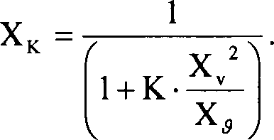


Priority Applications (9)
| Application Number | Priority Date | Filing Date | Title |
|---|---|---|---|
| DE102007030700A DE102007030700A1 (en) | 2007-06-30 | 2007-06-30 | Measuring system for a medium flowing in a process line |
| PCT/EP2008/058321 WO2009003963A2 (en) | 2007-06-30 | 2008-06-27 | Measuring system for a medium flowing in a process line |
| CA2691176A CA2691176C (en) | 2007-06-30 | 2008-06-27 | Measuring system for a medium flowing in a process line |
| EP08774480.1A EP2162724B1 (en) | 2007-06-30 | 2008-06-27 | Measuring system for a medium flowing in a process line |
| CN2008800219026A CN101711351B (en) | 2007-06-30 | 2008-06-27 | Measuring system for a medium flowing in a process line |
| US12/216,101 US8200450B2 (en) | 2007-06-30 | 2008-06-30 | Medium density measuring system |
| US12/216,100 US8010312B2 (en) | 2007-06-30 | 2008-06-30 | Medium density measuring system |
| US12/216,102 US8370098B2 (en) | 2007-06-30 | 2008-06-30 | Measuring system for a medium flowing in a process line |
| US12/216,103 US8447536B2 (en) | 2007-06-30 | 2008-06-30 | Medium density measuring system |
Applications Claiming Priority (1)
| Application Number | Priority Date | Filing Date | Title |
|---|---|---|---|
| DE102007030700A DE102007030700A1 (en) | 2007-06-30 | 2007-06-30 | Measuring system for a medium flowing in a process line |
Publications (1)
| Publication Number | Publication Date |
|---|---|
| DE102007030700A1 true DE102007030700A1 (en) | 2009-05-07 |
Family
ID=39865758
Family Applications (1)
| Application Number | Title | Priority Date | Filing Date |
|---|---|---|---|
| DE102007030700A Withdrawn DE102007030700A1 (en) | 2007-06-30 | 2007-06-30 | Measuring system for a medium flowing in a process line |
Country Status (5)
| Country | Link |
|---|---|
| EP (1) | EP2162724B1 (en) |
| CN (1) | CN101711351B (en) |
| CA (1) | CA2691176C (en) |
| DE (1) | DE102007030700A1 (en) |
| WO (1) | WO2009003963A2 (en) |
Cited By (8)
| Publication number | Priority date | Publication date | Assignee | Title |
|---|---|---|---|---|
| DE102010000760A1 (en) * | 2010-01-11 | 2011-07-14 | Endress + Hauser Flowtec Ag | Measuring system i.e. measuring device and/or Coriolis or mass flow measuring device for medium e.g. gas and/or liquid, flowing in pipeline, has transmitter electronics generating measured value |
| DE102010000761A1 (en) * | 2010-01-11 | 2011-07-28 | Endress + Hauser Flowtec Ag | Measuring system i.e. measuring device and/or Coriolis or mass flow measuring device for medium e.g. gas and/or liquid, flowing in pipeline, has transmitter electronics generating measured value |
| DE102010038573A1 (en) * | 2010-07-28 | 2012-02-02 | Endress + Hauser Gmbh + Co. Kg | Measuring method for a measured variable dependent on auxiliary measured variables |
| US8671776B2 (en) | 2009-12-31 | 2014-03-18 | Endress + Hauser Flowtec Ag | Measuring medium flow with a measuring transducer of the vibration type |
| WO2014067591A1 (en) * | 2012-10-31 | 2014-05-08 | Krohne Messtechnik Gmbh | Measuring device, measuring arrangement, and method for determining a measured variable |
| DE102015110050A1 (en) * | 2015-06-23 | 2016-12-29 | Endress + Hauser Flowtec Ag | Field device with compensation circuit for the elimination of environmental influences |
| DE102017012066A1 (en) * | 2017-12-29 | 2019-07-04 | Endress+Hauser Flowtec Ag | Flow meter according to the vortex meter principle, measuring tube therefor and method for measuring the flow or the flow velocity of a medium |
| DE102018130067A1 (en) * | 2018-11-28 | 2020-05-28 | Volkswagen Aktiengesellschaft | Process for measuring and regulating technical gas flows, device for measuring and regulating technical gas flows |
Families Citing this family (13)
| Publication number | Priority date | Publication date | Assignee | Title |
|---|---|---|---|---|
| DE102009001526A1 (en) | 2009-03-12 | 2010-09-16 | Endress + Hauser Flowtec Ag | A vortex flow meter for monitoring and / or measuring a distributed particle and / or droplet flow |
| PL2667176T3 (en) * | 2012-05-24 | 2015-07-31 | Air Prod & Chem | Apparatus for measuring the true contents of a cylinder of gas under pressure |
| US9612229B2 (en) * | 2013-05-24 | 2017-04-04 | Mems Ag | Method and measuring apparatus for determining physical properties of gas |
| DE102014113898A1 (en) | 2014-09-25 | 2016-03-31 | Endress+Hauser Flowtec Ag | measuring arrangement |
| DE102017126128A1 (en) | 2017-11-08 | 2019-05-09 | Endress+Hauser SE+Co. KG | System and method for the spatially resolved determination of at least one physical or chemical process variable |
| JP7069812B2 (en) * | 2018-02-22 | 2022-05-18 | 株式会社島津製作所 | Analytical liquid monitoring device |
| CN108758329A (en) * | 2018-06-19 | 2018-11-06 | 沈阳科汇生产力促进中心有限公司 | Filling machine, aerating statistical method, tax control filling machine and aerating tax control method |
| DE102018116640A1 (en) * | 2018-07-10 | 2020-01-16 | SIKA Dr. Siebert & Kühn GmbH & Co. KG | flowmeter |
| DE102018122014A1 (en) * | 2018-09-10 | 2020-03-12 | Endress + Hauser Flowtec Ag | Measuring system and measuring arrangement thus formed |
| WO2021050033A1 (en) * | 2019-09-09 | 2021-03-18 | Micro Motion, Inc. | Systems and methods for live determination of fluid energy content |
| CN110793579B (en) * | 2019-09-30 | 2020-10-02 | 天津市迅尔仪表科技有限公司 | Balance flowmeter |
| CN110940390B (en) * | 2019-12-03 | 2021-09-21 | 曹妃甸新天液化天然气有限公司 | Intelligent natural gas flow detection equipment |
| CN114689460B (en) * | 2022-06-01 | 2022-08-23 | 西北大学 | Crude oil density value correction method for online density automatic measurement |
Citations (71)
| Publication number | Priority date | Publication date | Assignee | Title |
|---|---|---|---|---|
| US4308754A (en) | 1979-10-19 | 1982-01-05 | Panametrics, Inc. | Ultrasonic flowmeter |
| US4420983A (en) | 1980-02-28 | 1983-12-20 | The Marconi Company Limited | Mass flow measurement device |
| US4468971A (en) | 1982-07-16 | 1984-09-04 | Fischer And Porter Company | Ultrasonic flowmeter for clean and dirty fluids |
| GB2142725A (en) | 1983-06-21 | 1985-01-23 | United Gas Industries Ltd | Fluid flow meter |
| US4524610A (en) | 1983-09-02 | 1985-06-25 | National Metal And Refining Company, Ltd. | In-line vibratory viscometer-densitometer |
| US4563904A (en) | 1984-09-12 | 1986-01-14 | Fischer & Porter Company | Excitation circuit for electromagnetic flowmeter |
| US4716770A (en) | 1985-12-13 | 1988-01-05 | Flowtec Ag | Vortex flow meter |
| WO1988002476A1 (en) | 1986-10-03 | 1988-04-07 | Micro Motion, Inc. | Custody transfer meter |
| WO1988002853A1 (en) | 1986-10-09 | 1988-04-21 | Micro Motion, Inc. | Apparatus and methods for measuring the density of an unknown fluid using a coriolis meter |
| US4768384A (en) | 1986-09-26 | 1988-09-06 | Flowtec Ag | Mass flow meter operating by the Coriolis principle |
| US4787252A (en) | 1987-09-30 | 1988-11-29 | Panametrics, Inc. | Differential correlation analyzer |
| US5052229A (en) | 1989-05-23 | 1991-10-01 | Mitsubishi Jidosha Kogyo Kabushiki Kaisha | Vortex flowmeter |
| US5052230A (en) | 1988-07-08 | 1991-10-01 | Flowtec Ag | Method and arrangement for flow rate measurement by means of ultrasonic waves |
| US5131279A (en) | 1990-05-19 | 1992-07-21 | Flowtec Ag | Sensing element for an ultrasonic volumetric flowmeter |
| US5231884A (en) | 1991-07-11 | 1993-08-03 | Micro Motion, Inc. | Technique for substantially eliminating temperature induced measurement errors from a coriolis meter |
| EP0605944A2 (en) | 1992-10-06 | 1994-07-13 | Caldon, Inc. | Apparatus for determining fluid flow |
| US5351554A (en) | 1991-06-08 | 1994-10-04 | Endress + Hauser Flowtec Ag | Magnetoinductive flowmeter |
| US5359881A (en) | 1992-03-20 | 1994-11-01 | Micro Motion, Incorporated | Viscometer for sanitary applications |
| WO1995008758A1 (en) | 1993-09-20 | 1995-03-30 | Rosemount Inc. | Differential pressure measurement arrangement utilizing dual transmitters |
| WO1995016897A2 (en) | 1993-12-15 | 1995-06-22 | Direct Measurement Corp. | Single path radial mode coriolis mass flow rate meter |
| US5458005A (en) | 1992-07-15 | 1995-10-17 | Abbk-Flow Inc. | Fluid mass flow meters |
| US5463905A (en) | 1993-02-23 | 1995-11-07 | Baird; James D. | Portable non-invasive flowmeter for partially filled pipe |
| US5469748A (en) | 1994-07-20 | 1995-11-28 | Micro Motion, Inc. | Noise reduction filter system for a coriolis flowmeter |
| US5531124A (en) | 1993-08-25 | 1996-07-02 | Changmin Technology Co., Ltd. | Ultrasonic flow measuring method and apparatus thereof |
| US5540103A (en) | 1993-10-14 | 1996-07-30 | Endress+Hauser Flowtec Ag | Electromagnetic flow sensor |
| WO1997025595A1 (en) | 1996-01-04 | 1997-07-17 | Rosemount Inc. | Flowmeter with pitot tube with average pressure |
| US5687100A (en) | 1996-07-16 | 1997-11-11 | Micro Motion, Inc. | Vibrating tube densimeter |
| WO1997046851A2 (en) | 1996-05-17 | 1997-12-11 | Dieterich Technology Holding Corp. | Method for calibrating a flow measuring system |
| WO1997048970A2 (en) | 1996-06-04 | 1997-12-24 | Dieterich Technology Holding Corp. | Flow meter pitot tube with temperature sensor |
| US5796011A (en) | 1993-07-20 | 1998-08-18 | Endress + Hauser Flowtech Ag | Coriolis-type mass flow sensor |
| US5808209A (en) | 1994-03-23 | 1998-09-15 | Schlumberger Industries, S.A. | Vortex fluid meter including a profiled pipe |
| WO1998043051A2 (en) | 1997-03-27 | 1998-10-01 | Rosemount Inc. | Vortex flowmeter with signal processing |
| EP0903651A1 (en) | 1997-09-18 | 1999-03-24 | Endress + Hauser Gmbh + Co. | Measuring device / bus system interface and adapter therefor |
| US6003384A (en) | 1996-11-08 | 1999-12-21 | Endress +Hauser Flowtec Ag | Vortex flow sensor with a capacitive sensing element |
| US6006609A (en) | 1996-12-11 | 1999-12-28 | Endress + Hauser Flowtec Ag | Coriolis mass flow/density sensor with a single straight measuring tube |
| US6031740A (en) | 1998-07-03 | 2000-02-29 | Endress + Hauser Flowtec Ag | Method of regulating the coil current of electromagnetic flow sensors |
| EP0984248A1 (en) | 1998-09-02 | 2000-03-08 | Endress + Hauser GmbH + Co. | Measurement detector |
| WO2000014485A1 (en) | 1998-09-08 | 2000-03-16 | Krohne Messtechnik Gmbh & Co. Kg | Straight coriolis-type mass flowmeter with compensation cylinder |
| US6053054A (en) | 1997-09-26 | 2000-04-25 | Fti Flow Technology, Inc. | Gas flow rate measurement apparatus and method |
| EP1008836A1 (en) | 1998-12-11 | 2000-06-14 | Endress + Hauser GmbH + Co. | Transmitter housing |
| WO2000036379A1 (en) | 1998-12-11 | 2000-06-22 | Endress + Hauser Flowtec Ag | Coriolis-type mass flowmeter/densimeter |
| EP1039269A1 (en) | 1999-03-26 | 2000-09-27 | Endress + Hauser Flowtec AG | Electromagnetic flow sensor and method of manufacturing the same |
| WO2001002816A2 (en) | 1999-06-30 | 2001-01-11 | Micro Motion, Inc. | Temperature compensation for straight tube coriolis flowmeter |
| US6189389B1 (en) | 1996-05-28 | 2001-02-20 | Krohne A.G. | Ultrasonic flowmeter |
| US6293156B1 (en) | 1999-01-22 | 2001-09-25 | Panametrics, Inc. | Coherent multi-path flow measurement system |
| US6330831B1 (en) | 1998-10-20 | 2001-12-18 | Panametrics, Inc. | Stream-cleaned differential reflection coefficient sensor |
| US6352000B1 (en) | 1998-08-12 | 2002-03-05 | Flowtec Ag | Vortex flow sensor |
| US6397683B1 (en) | 1998-07-22 | 2002-06-04 | Flowtec Ag | Clamp-on ultrasonic flowmeter |
| US20020096208A1 (en) | 2000-12-06 | 2002-07-25 | Haldor Topsoe A/S | Method for determination of mass flow and density of a process stream |
| WO2002086426A1 (en) | 2001-04-24 | 2002-10-31 | Endress + Hauser Flowtec Ag | Vibration-type measuring transformer |
| US6513393B1 (en) | 1998-12-11 | 2003-02-04 | Flowtec Ag | Coriolis mass/flow density meter |
| US6644132B1 (en) | 1999-05-06 | 2003-11-11 | Joseph Baumoel | Flow profile conditioner for pipe flow systems |
| US6651513B2 (en) | 2000-04-27 | 2003-11-25 | Endress + Hauser Flowtec Ag | Vibration meter and method of measuring a viscosity of a fluid |
| WO2003098154A1 (en) | 2002-05-15 | 2003-11-27 | Endress + Hauser Flowtec Ag | Variable field device for process automation |
| US6681189B1 (en) * | 2001-08-22 | 2004-01-20 | The Texas A&M University System | Method and system for determining flow rates and/or fluid density in single and multiple-phase flows utilizing discharge coefficient relationships |
| WO2004023081A2 (en) | 2002-09-06 | 2004-03-18 | Invensys Systems, Inc. | Multi-measurement vortex flow meter |
| WO2004081500A2 (en) | 2003-03-12 | 2004-09-23 | Rosemount, Inc. | Flowmeter with multisensors |
| US20040255695A1 (en) | 2002-11-15 | 2004-12-23 | Gysling Daniel L. | Apparatus and method for providing a flow measurement compensated for entrained gas |
| US20050043900A1 (en) * | 2003-08-21 | 2005-02-24 | Franda Robert Josef | Apparatus and method for real time determination of density and related parameters in manufacturing processes |
| US6880410B2 (en) | 2002-03-14 | 2005-04-19 | Endress + Hauser Flowtec Ag | Transducer and method for measuring a fluid flowing in a pipe |
| US20050092101A1 (en) | 2003-11-03 | 2005-05-05 | Rosemount Inc. | Flanged vortex flowmeter with unitary tapered expanders |
| US6910387B2 (en) | 2002-09-04 | 2005-06-28 | Endress + Hausser Flowtec Ag | Vortex flow sensor for measuring fluid flow through a flow tube |
| US6938496B2 (en) | 2001-09-04 | 2005-09-06 | Endress + Hauser Flowtec Ag | Vortex flow pickup |
| WO2005095902A1 (en) | 2004-03-25 | 2005-10-13 | Rosemount Inc. | Simplified fluid property measurement |
| US20060025955A1 (en) * | 2004-07-29 | 2006-02-02 | Kurtz Anthony D | Gas density transducer |
| US7010366B2 (en) | 2001-07-06 | 2006-03-07 | Endress & Hauser Wetzer Gmbh & Co. Kg | Field device with display |
| US7007556B2 (en) | 2002-08-28 | 2006-03-07 | Endress + Hauser Flowtec Ag | Method for determining a mass flow of a fluid flowing in a pipe |
| US20060266127A1 (en) | 2005-05-27 | 2006-11-30 | Gysling Daniel L | Apparatus and method for fiscal measuring of an aerated fluid |
| EP1767908A1 (en) | 2004-07-15 | 2007-03-28 | Oval Corporation | Multi-vortex flow meter |
| DE102006034296A1 (en) | 2006-07-21 | 2008-01-24 | Endress + Hauser Flowtec Ag | Measuring system for detecting measured variable, particularly mass flow, volume flow, flow rate, density, viscosity, has measuring sensor, with particularly straight measuring tube, which serves to guide medium which is to be measured |
| DE102006047815A1 (en) | 2006-10-06 | 2008-04-10 | Endress + Hauser Flowtec Ag | Measuring system e.g. magnetic-inductive flow measuring system, for detecting measurement variable e.g. mass flow of medium, has flow conditioner with inner edge that is provided upstream of outlet end of conditioner and projects into lumen |
Family Cites Families (9)
| Publication number | Priority date | Publication date | Assignee | Title |
|---|---|---|---|---|
| US3701280A (en) * | 1970-03-18 | 1972-10-31 | Daniel Ind Inc | Method and apparatus for determining the supercompressibility factor of natural gas |
| GB2079465B (en) * | 1980-07-02 | 1984-06-27 | Nat Res Dev | Measurement of true density |
| DE3624093A1 (en) * | 1986-07-17 | 1988-01-21 | Piller Gmbh Co Kg Anton | Device for measuring the density of flowing gases |
| US4893496A (en) * | 1988-10-14 | 1990-01-16 | Panametrics, Inc. | Torsional wave fluid sensor and system |
| US5132917A (en) * | 1990-04-23 | 1992-07-21 | Shell Oil Company | Method and apparatus for the combined use of dual density measurements to achieve a fast and accurate density measurement in pneumatically transported solids |
| US5447073A (en) * | 1994-02-04 | 1995-09-05 | The Foxboro Company | Multimeasurement replaceable vortex sensor |
| DE69900979T2 (en) * | 1998-04-23 | 2002-09-12 | Lattice Intellectual Property | MEASUREMENT OF A GAS MASS BREAKAGE PART |
| DE10044491A1 (en) * | 2000-09-08 | 2002-04-04 | Komponenten Maschb Gmbh 2 | Density measurement equipment for gas charged, pressurized fluid plastic comprises pressure sensor, density measuring cell and control unit to determine fluid density under standard conditions |
| CN100405047C (en) * | 2005-05-11 | 2008-07-23 | 中国科学院力学研究所 | Apparatus and method for measuring conducting fluid density |
-
2007
- 2007-06-30 DE DE102007030700A patent/DE102007030700A1/en not_active Withdrawn
-
2008
- 2008-06-27 CA CA2691176A patent/CA2691176C/en active Active
- 2008-06-27 CN CN2008800219026A patent/CN101711351B/en active Active
- 2008-06-27 EP EP08774480.1A patent/EP2162724B1/en active Active
- 2008-06-27 WO PCT/EP2008/058321 patent/WO2009003963A2/en active Application Filing
Patent Citations (73)
| Publication number | Priority date | Publication date | Assignee | Title |
|---|---|---|---|---|
| US4308754A (en) | 1979-10-19 | 1982-01-05 | Panametrics, Inc. | Ultrasonic flowmeter |
| US4420983A (en) | 1980-02-28 | 1983-12-20 | The Marconi Company Limited | Mass flow measurement device |
| US4468971A (en) | 1982-07-16 | 1984-09-04 | Fischer And Porter Company | Ultrasonic flowmeter for clean and dirty fluids |
| GB2142725A (en) | 1983-06-21 | 1985-01-23 | United Gas Industries Ltd | Fluid flow meter |
| US4524610A (en) | 1983-09-02 | 1985-06-25 | National Metal And Refining Company, Ltd. | In-line vibratory viscometer-densitometer |
| US4563904A (en) | 1984-09-12 | 1986-01-14 | Fischer & Porter Company | Excitation circuit for electromagnetic flowmeter |
| US4716770A (en) | 1985-12-13 | 1988-01-05 | Flowtec Ag | Vortex flow meter |
| US4768384A (en) | 1986-09-26 | 1988-09-06 | Flowtec Ag | Mass flow meter operating by the Coriolis principle |
| WO1988002476A1 (en) | 1986-10-03 | 1988-04-07 | Micro Motion, Inc. | Custody transfer meter |
| WO1988002853A1 (en) | 1986-10-09 | 1988-04-21 | Micro Motion, Inc. | Apparatus and methods for measuring the density of an unknown fluid using a coriolis meter |
| US4787252A (en) | 1987-09-30 | 1988-11-29 | Panametrics, Inc. | Differential correlation analyzer |
| US5052230A (en) | 1988-07-08 | 1991-10-01 | Flowtec Ag | Method and arrangement for flow rate measurement by means of ultrasonic waves |
| US5052229A (en) | 1989-05-23 | 1991-10-01 | Mitsubishi Jidosha Kogyo Kabushiki Kaisha | Vortex flowmeter |
| US5131279A (en) | 1990-05-19 | 1992-07-21 | Flowtec Ag | Sensing element for an ultrasonic volumetric flowmeter |
| US5351554A (en) | 1991-06-08 | 1994-10-04 | Endress + Hauser Flowtec Ag | Magnetoinductive flowmeter |
| US5231884A (en) | 1991-07-11 | 1993-08-03 | Micro Motion, Inc. | Technique for substantially eliminating temperature induced measurement errors from a coriolis meter |
| US5359881A (en) | 1992-03-20 | 1994-11-01 | Micro Motion, Incorporated | Viscometer for sanitary applications |
| US5458005A (en) | 1992-07-15 | 1995-10-17 | Abbk-Flow Inc. | Fluid mass flow meters |
| EP0605944A2 (en) | 1992-10-06 | 1994-07-13 | Caldon, Inc. | Apparatus for determining fluid flow |
| US5463905A (en) | 1993-02-23 | 1995-11-07 | Baird; James D. | Portable non-invasive flowmeter for partially filled pipe |
| US5796011A (en) | 1993-07-20 | 1998-08-18 | Endress + Hauser Flowtech Ag | Coriolis-type mass flow sensor |
| US5531124A (en) | 1993-08-25 | 1996-07-02 | Changmin Technology Co., Ltd. | Ultrasonic flow measuring method and apparatus thereof |
| WO1995008758A1 (en) | 1993-09-20 | 1995-03-30 | Rosemount Inc. | Differential pressure measurement arrangement utilizing dual transmitters |
| US5540103A (en) | 1993-10-14 | 1996-07-30 | Endress+Hauser Flowtec Ag | Electromagnetic flow sensor |
| WO1995016897A2 (en) | 1993-12-15 | 1995-06-22 | Direct Measurement Corp. | Single path radial mode coriolis mass flow rate meter |
| US5808209A (en) | 1994-03-23 | 1998-09-15 | Schlumberger Industries, S.A. | Vortex fluid meter including a profiled pipe |
| US5469748A (en) | 1994-07-20 | 1995-11-28 | Micro Motion, Inc. | Noise reduction filter system for a coriolis flowmeter |
| WO1997025595A1 (en) | 1996-01-04 | 1997-07-17 | Rosemount Inc. | Flowmeter with pitot tube with average pressure |
| WO1997046851A2 (en) | 1996-05-17 | 1997-12-11 | Dieterich Technology Holding Corp. | Method for calibrating a flow measuring system |
| US6189389B1 (en) | 1996-05-28 | 2001-02-20 | Krohne A.G. | Ultrasonic flowmeter |
| WO1997048970A2 (en) | 1996-06-04 | 1997-12-24 | Dieterich Technology Holding Corp. | Flow meter pitot tube with temperature sensor |
| US5687100A (en) | 1996-07-16 | 1997-11-11 | Micro Motion, Inc. | Vibrating tube densimeter |
| US6003384A (en) | 1996-11-08 | 1999-12-21 | Endress +Hauser Flowtec Ag | Vortex flow sensor with a capacitive sensing element |
| US6006609A (en) | 1996-12-11 | 1999-12-28 | Endress + Hauser Flowtec Ag | Coriolis mass flow/density sensor with a single straight measuring tube |
| WO1998043051A2 (en) | 1997-03-27 | 1998-10-01 | Rosemount Inc. | Vortex flowmeter with signal processing |
| US6651512B1 (en) | 1997-03-27 | 2003-11-25 | Rosemount, Inc. | Ancillary process outputs of a vortex flowmeter |
| EP0903651A1 (en) | 1997-09-18 | 1999-03-24 | Endress + Hauser Gmbh + Co. | Measuring device / bus system interface and adapter therefor |
| US6053054A (en) | 1997-09-26 | 2000-04-25 | Fti Flow Technology, Inc. | Gas flow rate measurement apparatus and method |
| US6031740A (en) | 1998-07-03 | 2000-02-29 | Endress + Hauser Flowtec Ag | Method of regulating the coil current of electromagnetic flow sensors |
| US6397683B1 (en) | 1998-07-22 | 2002-06-04 | Flowtec Ag | Clamp-on ultrasonic flowmeter |
| US6352000B1 (en) | 1998-08-12 | 2002-03-05 | Flowtec Ag | Vortex flow sensor |
| EP0984248A1 (en) | 1998-09-02 | 2000-03-08 | Endress + Hauser GmbH + Co. | Measurement detector |
| WO2000014485A1 (en) | 1998-09-08 | 2000-03-16 | Krohne Messtechnik Gmbh & Co. Kg | Straight coriolis-type mass flowmeter with compensation cylinder |
| US6330831B1 (en) | 1998-10-20 | 2001-12-18 | Panametrics, Inc. | Stream-cleaned differential reflection coefficient sensor |
| US6513393B1 (en) | 1998-12-11 | 2003-02-04 | Flowtec Ag | Coriolis mass/flow density meter |
| WO2000036379A1 (en) | 1998-12-11 | 2000-06-22 | Endress + Hauser Flowtec Ag | Coriolis-type mass flowmeter/densimeter |
| EP1008836A1 (en) | 1998-12-11 | 2000-06-14 | Endress + Hauser GmbH + Co. | Transmitter housing |
| US6293156B1 (en) | 1999-01-22 | 2001-09-25 | Panametrics, Inc. | Coherent multi-path flow measurement system |
| EP1039269A1 (en) | 1999-03-26 | 2000-09-27 | Endress + Hauser Flowtec AG | Electromagnetic flow sensor and method of manufacturing the same |
| US6644132B1 (en) | 1999-05-06 | 2003-11-11 | Joseph Baumoel | Flow profile conditioner for pipe flow systems |
| WO2001002816A2 (en) | 1999-06-30 | 2001-01-11 | Micro Motion, Inc. | Temperature compensation for straight tube coriolis flowmeter |
| US6651513B2 (en) | 2000-04-27 | 2003-11-25 | Endress + Hauser Flowtec Ag | Vibration meter and method of measuring a viscosity of a fluid |
| US20020096208A1 (en) | 2000-12-06 | 2002-07-25 | Haldor Topsoe A/S | Method for determination of mass flow and density of a process stream |
| WO2002086426A1 (en) | 2001-04-24 | 2002-10-31 | Endress + Hauser Flowtec Ag | Vibration-type measuring transformer |
| US7010366B2 (en) | 2001-07-06 | 2006-03-07 | Endress & Hauser Wetzer Gmbh & Co. Kg | Field device with display |
| US6681189B1 (en) * | 2001-08-22 | 2004-01-20 | The Texas A&M University System | Method and system for determining flow rates and/or fluid density in single and multiple-phase flows utilizing discharge coefficient relationships |
| US6938496B2 (en) | 2001-09-04 | 2005-09-06 | Endress + Hauser Flowtec Ag | Vortex flow pickup |
| US6988418B2 (en) | 2001-09-04 | 2006-01-24 | Endress + Hauser Flowtec Ag | Vortex flow pickup |
| US6880410B2 (en) | 2002-03-14 | 2005-04-19 | Endress + Hauser Flowtec Ag | Transducer and method for measuring a fluid flowing in a pipe |
| WO2003098154A1 (en) | 2002-05-15 | 2003-11-27 | Endress + Hauser Flowtec Ag | Variable field device for process automation |
| US7007556B2 (en) | 2002-08-28 | 2006-03-07 | Endress + Hauser Flowtec Ag | Method for determining a mass flow of a fluid flowing in a pipe |
| US6910387B2 (en) | 2002-09-04 | 2005-06-28 | Endress + Hausser Flowtec Ag | Vortex flow sensor for measuring fluid flow through a flow tube |
| WO2004023081A2 (en) | 2002-09-06 | 2004-03-18 | Invensys Systems, Inc. | Multi-measurement vortex flow meter |
| US20040255695A1 (en) | 2002-11-15 | 2004-12-23 | Gysling Daniel L. | Apparatus and method for providing a flow measurement compensated for entrained gas |
| WO2004081500A2 (en) | 2003-03-12 | 2004-09-23 | Rosemount, Inc. | Flowmeter with multisensors |
| US20050043900A1 (en) * | 2003-08-21 | 2005-02-24 | Franda Robert Josef | Apparatus and method for real time determination of density and related parameters in manufacturing processes |
| US20050092101A1 (en) | 2003-11-03 | 2005-05-05 | Rosemount Inc. | Flanged vortex flowmeter with unitary tapered expanders |
| WO2005095902A1 (en) | 2004-03-25 | 2005-10-13 | Rosemount Inc. | Simplified fluid property measurement |
| EP1767908A1 (en) | 2004-07-15 | 2007-03-28 | Oval Corporation | Multi-vortex flow meter |
| US20060025955A1 (en) * | 2004-07-29 | 2006-02-02 | Kurtz Anthony D | Gas density transducer |
| US20060266127A1 (en) | 2005-05-27 | 2006-11-30 | Gysling Daniel L | Apparatus and method for fiscal measuring of an aerated fluid |
| DE102006034296A1 (en) | 2006-07-21 | 2008-01-24 | Endress + Hauser Flowtec Ag | Measuring system for detecting measured variable, particularly mass flow, volume flow, flow rate, density, viscosity, has measuring sensor, with particularly straight measuring tube, which serves to guide medium which is to be measured |
| DE102006047815A1 (en) | 2006-10-06 | 2008-04-10 | Endress + Hauser Flowtec Ag | Measuring system e.g. magnetic-inductive flow measuring system, for detecting measurement variable e.g. mass flow of medium, has flow conditioner with inner edge that is provided upstream of outlet end of conditioner and projects into lumen |
Non-Patent Citations (4)
| Title |
|---|
| "High Accuracy Compressibility Factor Calculation for Natural Gases and Similar Mixtures by Use of a Truncated Viral Equation", GERG Technical Monograph TM2 1998 & Fortschritt-Berichte VDI, Series 6, No. 231 1989 (SGERG-88) |
| "IAWPS Industrial Formulation 1997 for the Thermodynamic Properties of Water and Steam", International Association for the Properties of Water and Steam (IAWPS-IF97), "A. G. A. Manual for the Determination of Supercompressibility Factors for Natural Gas - PAR Research Project NX-19", Amercian Gas Association (AGA-NX19, Library of Congress No. 63-23358) |
| A. G. A. Compressibility Factors for Natural Gas and Other Related Hydrocarbon Gases", Amercian Gas Association Transmission Measurement Committee Report No. 8 (AGA-8) |
| ISO 12213: 2006, Part 1-3 "Natural gas - Calculation of compressin factor" |
Cited By (15)
| Publication number | Priority date | Publication date | Assignee | Title |
|---|---|---|---|---|
| US8671776B2 (en) | 2009-12-31 | 2014-03-18 | Endress + Hauser Flowtec Ag | Measuring medium flow with a measuring transducer of the vibration type |
| DE102010000761A1 (en) * | 2010-01-11 | 2011-07-28 | Endress + Hauser Flowtec Ag | Measuring system i.e. measuring device and/or Coriolis or mass flow measuring device for medium e.g. gas and/or liquid, flowing in pipeline, has transmitter electronics generating measured value |
| DE102010000760A1 (en) * | 2010-01-11 | 2011-07-14 | Endress + Hauser Flowtec Ag | Measuring system i.e. measuring device and/or Coriolis or mass flow measuring device for medium e.g. gas and/or liquid, flowing in pipeline, has transmitter electronics generating measured value |
| DE102010038573B4 (en) | 2010-07-28 | 2023-08-31 | Endress+Hauser SE+Co. KG | Measurement method for a measurand dependent on auxiliary measurands |
| DE102010038573A1 (en) * | 2010-07-28 | 2012-02-02 | Endress + Hauser Gmbh + Co. Kg | Measuring method for a measured variable dependent on auxiliary measured variables |
| US9689708B2 (en) | 2010-07-28 | 2017-06-27 | Endress + Hauser Gmbh + Co. Kg | Measuring method for a measured variable dependent on auxiliary measured variables |
| WO2014067591A1 (en) * | 2012-10-31 | 2014-05-08 | Krohne Messtechnik Gmbh | Measuring device, measuring arrangement, and method for determining a measured variable |
| DE102012021312B4 (en) * | 2012-10-31 | 2015-05-07 | Krohne Messtechnik Gmbh | Measuring device, measuring arrangement and method for determining a measured variable |
| RU2641512C2 (en) * | 2012-10-31 | 2018-01-17 | Кроне Месстехник Гмбх | Measuring system and method of determining the measuring value |
| DE102015110050A1 (en) * | 2015-06-23 | 2016-12-29 | Endress + Hauser Flowtec Ag | Field device with compensation circuit for the elimination of environmental influences |
| US10746581B2 (en) | 2015-06-23 | 2020-08-18 | Endress + Hauser Flowtec Ag | Field device with compensation circuit for eliminating environmental influences |
| CN111566453A (en) * | 2017-12-29 | 2020-08-21 | 恩德斯+豪斯流量技术股份有限公司 | Flowmeter arrangement according to the vortex measurement principle, measuring tube therefor and method for measuring the flow or velocity of a medium |
| US11408757B2 (en) | 2017-12-29 | 2022-08-09 | Endress+Hauser Flowtec Ag | Flow meter device according to the vortex measuring principle, measuring tube for same, and method for measuring the flow rate or the flow speed of a medium |
| DE102017012066A1 (en) * | 2017-12-29 | 2019-07-04 | Endress+Hauser Flowtec Ag | Flow meter according to the vortex meter principle, measuring tube therefor and method for measuring the flow or the flow velocity of a medium |
| DE102018130067A1 (en) * | 2018-11-28 | 2020-05-28 | Volkswagen Aktiengesellschaft | Process for measuring and regulating technical gas flows, device for measuring and regulating technical gas flows |
Also Published As
| Publication number | Publication date |
|---|---|
| EP2162724A2 (en) | 2010-03-17 |
| WO2009003963A3 (en) | 2009-03-05 |
| WO2009003963A2 (en) | 2009-01-08 |
| CA2691176A1 (en) | 2009-01-08 |
| CN101711351A (en) | 2010-05-19 |
| CA2691176C (en) | 2015-12-08 |
| CN101711351B (en) | 2012-04-11 |
| EP2162724B1 (en) | 2019-06-05 |
Similar Documents
| Publication | Publication Date | Title |
|---|---|---|
| EP2162724B1 (en) | Measuring system for a medium flowing in a process line | |
| EP2162707B1 (en) | Measuring system for a medium flowing in a process line | |
| EP2162706B1 (en) | Measuring system for a medium flowing in a process line | |
| DE102007030691A1 (en) | Measuring system for a medium flowing in a process line | |
| EP2519805B1 (en) | Measuring system comprising a vibration-type transducer and method for measuring a pressure difference | |
| EP2795287B1 (en) | Method and measurement system for determining a density of a fluid | |
| EP2715542B1 (en) | Electronic circuit for a measuring apparatus and method of checking the apparatus | |
| EP2606319B1 (en) | Measuring system with a measuring transducer of a vibration type | |
| EP2227677B1 (en) | Measuring system for a medium flowing in a process line | |
| WO2012062551A1 (en) | Measuring system having a vibration-type measuring transducer | |
| EP2519806B1 (en) | Measuring system with vibration type transducer | |
| WO2008009720A2 (en) | Measuring system for a medium flowing in a process line | |
| DE102006034296A1 (en) | Measuring system for detecting measured variable, particularly mass flow, volume flow, flow rate, density, viscosity, has measuring sensor, with particularly straight measuring tube, which serves to guide medium which is to be measured | |
| EP2457066A1 (en) | Vibration-type transducer and measurement device comprising said transducer | |
| DE102005046319A1 (en) | Two or multi-phase medium e.g. fluid`s, physical flow parameter e.g. flow rate, measuring method, involves producing measurement values representing parameter by considering pressure difference of medium and by usage of transfer function | |
| EP2742325A1 (en) | Sensor module for measuring and/or monitoring parameters of media flowing in pipelines and measuring system formed therewith | |
| WO2019211074A1 (en) | Measuring system and method for measuring a measurement variable of a flowing fluid | |
| EP3894798B1 (en) | Measurement system for measuring a parameter of a fluid in a pipe | |
| EP2519804B1 (en) | Measuring system comprising a vibration-type transducer | |
| EP3241011B1 (en) | Method for measuring the density of a fluid | |
| DE102014019396A1 (en) | Method for measuring a density of a fluid | |
| DE10321003B4 (en) | Method for measuring flow rates, as well as flow meters | |
| DE102010000761A1 (en) | Measuring system i.e. measuring device and/or Coriolis or mass flow measuring device for medium e.g. gas and/or liquid, flowing in pipeline, has transmitter electronics generating measured value |
Legal Events
| Date | Code | Title | Description |
|---|---|---|---|
| OM8 | Search report available as to paragraph 43 lit. 1 sentence 1 patent law | ||
| 8139 | Disposal/non-payment of the annual fee |