DE102010003421A1 - Energy storage device operating method for e.g. hybrid car, involves determining initial sizes of energy storage voltage and current, determining two state of charge, and determining state of charge loss dependent on two state of charge - Google Patents
Energy storage device operating method for e.g. hybrid car, involves determining initial sizes of energy storage voltage and current, determining two state of charge, and determining state of charge loss dependent on two state of charge Download PDFInfo
- Publication number
- DE102010003421A1 DE102010003421A1 DE102010003421A DE102010003421A DE102010003421A1 DE 102010003421 A1 DE102010003421 A1 DE 102010003421A1 DE 102010003421 A DE102010003421 A DE 102010003421A DE 102010003421 A DE102010003421 A DE 102010003421A DE 102010003421 A1 DE102010003421 A1 DE 102010003421A1
- Authority
- DE
- Germany
- Prior art keywords
- state
- charge
- energy storage
- determined
- operating
- Prior art date
- Legal status (The legal status is an assumption and is not a legal conclusion. Google has not performed a legal analysis and makes no representation as to the accuracy of the status listed.)
- Granted
Links
Images


Classifications
-
- H—ELECTRICITY
- H01—ELECTRIC ELEMENTS
- H01M—PROCESSES OR MEANS, e.g. BATTERIES, FOR THE DIRECT CONVERSION OF CHEMICAL ENERGY INTO ELECTRICAL ENERGY
- H01M10/00—Secondary cells; Manufacture thereof
- H01M10/42—Methods or arrangements for servicing or maintenance of secondary cells or secondary half-cells
- H01M10/44—Methods for charging or discharging
-
- B—PERFORMING OPERATIONS; TRANSPORTING
- B60—VEHICLES IN GENERAL
- B60L—PROPULSION OF ELECTRICALLY-PROPELLED VEHICLES; SUPPLYING ELECTRIC POWER FOR AUXILIARY EQUIPMENT OF ELECTRICALLY-PROPELLED VEHICLES; ELECTRODYNAMIC BRAKE SYSTEMS FOR VEHICLES IN GENERAL; MAGNETIC SUSPENSION OR LEVITATION FOR VEHICLES; MONITORING OPERATING VARIABLES OF ELECTRICALLY-PROPELLED VEHICLES; ELECTRIC SAFETY DEVICES FOR ELECTRICALLY-PROPELLED VEHICLES
- B60L58/00—Methods or circuit arrangements for monitoring or controlling batteries or fuel cells, specially adapted for electric vehicles
- B60L58/10—Methods or circuit arrangements for monitoring or controlling batteries or fuel cells, specially adapted for electric vehicles for monitoring or controlling batteries
- B60L58/12—Methods or circuit arrangements for monitoring or controlling batteries or fuel cells, specially adapted for electric vehicles for monitoring or controlling batteries responding to state of charge [SoC]
-
- G—PHYSICS
- G01—MEASURING; TESTING
- G01R—MEASURING ELECTRIC VARIABLES; MEASURING MAGNETIC VARIABLES
- G01R31/00—Arrangements for testing electric properties; Arrangements for locating electric faults; Arrangements for electrical testing characterised by what is being tested not provided for elsewhere
- G01R31/36—Arrangements for testing, measuring or monitoring the electrical condition of accumulators or electric batteries, e.g. capacity or state of charge [SoC]
- G01R31/382—Arrangements for monitoring battery or accumulator variables, e.g. SoC
- G01R31/3842—Arrangements for monitoring battery or accumulator variables, e.g. SoC combining voltage and current measurements
-
- H—ELECTRICITY
- H01—ELECTRIC ELEMENTS
- H01M—PROCESSES OR MEANS, e.g. BATTERIES, FOR THE DIRECT CONVERSION OF CHEMICAL ENERGY INTO ELECTRICAL ENERGY
- H01M10/00—Secondary cells; Manufacture thereof
- H01M10/42—Methods or arrangements for servicing or maintenance of secondary cells or secondary half-cells
- H01M10/48—Accumulators combined with arrangements for measuring, testing or indicating the condition of cells, e.g. the level or density of the electrolyte
-
- Y—GENERAL TAGGING OF NEW TECHNOLOGICAL DEVELOPMENTS; GENERAL TAGGING OF CROSS-SECTIONAL TECHNOLOGIES SPANNING OVER SEVERAL SECTIONS OF THE IPC; TECHNICAL SUBJECTS COVERED BY FORMER USPC CROSS-REFERENCE ART COLLECTIONS [XRACs] AND DIGESTS
- Y02—TECHNOLOGIES OR APPLICATIONS FOR MITIGATION OR ADAPTATION AGAINST CLIMATE CHANGE
- Y02E—REDUCTION OF GREENHOUSE GAS [GHG] EMISSIONS, RELATED TO ENERGY GENERATION, TRANSMISSION OR DISTRIBUTION
- Y02E60/00—Enabling technologies; Technologies with a potential or indirect contribution to GHG emissions mitigation
- Y02E60/10—Energy storage using batteries
-
- Y—GENERAL TAGGING OF NEW TECHNOLOGICAL DEVELOPMENTS; GENERAL TAGGING OF CROSS-SECTIONAL TECHNOLOGIES SPANNING OVER SEVERAL SECTIONS OF THE IPC; TECHNICAL SUBJECTS COVERED BY FORMER USPC CROSS-REFERENCE ART COLLECTIONS [XRACs] AND DIGESTS
- Y02—TECHNOLOGIES OR APPLICATIONS FOR MITIGATION OR ADAPTATION AGAINST CLIMATE CHANGE
- Y02T—CLIMATE CHANGE MITIGATION TECHNOLOGIES RELATED TO TRANSPORTATION
- Y02T10/00—Road transport of goods or passengers
- Y02T10/60—Other road transportation technologies with climate change mitigation effect
- Y02T10/70—Energy storage systems for electromobility, e.g. batteries
Abstract
Description
Die Erfindung betrifft ein Verfahren und eine Vorrichtung zum Betreiben eines Energiespeichers, bei dem beziehungsweise bei der ein erster Ladezustand und ein zweiter Ladezustand eines Energiespeichers ermittelt werden.The invention relates to a method and a device for operating an energy store, in which or in which a first state of charge and a second state of charge of an energy store are determined.
Aufgrund einer geringen CO2-Emission nimmt das Interesse an batteriebetriebenen Fahrzeugen, insbesondere an Fahrzeugen mit Hybridantrieb, sehr stark zu. Fahrzeuge mit Hybridantrieb weisen im Vergleich zu konventionellen Fahrzeugen einen zusätzlichen Energiespeicher auf, in welchem zurückgewonnene Energie abgespeichert werden kann. Für die Funktion von batteriebetriebenen Fahrzeugen und Hybridfahrzeugen spielt die Leistungsfähigkeit des Energiespeichers eine wesentliche Rolle. Viele moderne Energiespeichersysteme, die beispielsweise in Hybridfahrzeugen und Batteriefahrzeugen eingesetzt werden, verfügen über eine Überwachungs- und Batteriemanagementelektronik.Due to low CO 2 emissions, interest in battery-powered vehicles, especially hybrid-powered vehicles, is growing rapidly. Vehicles with hybrid drive have in comparison to conventional vehicles on an additional energy storage in which recovered energy can be stored. For the function of battery-powered vehicles and hybrid vehicles, the performance of the energy storage plays an essential role. Many modern energy storage systems used in hybrid vehicles and battery vehicles, for example, have monitoring and battery management electronics.
Die Aufgabe, die der Erfindung zugrunde liegt, ist, ein Verfahren und eine Vorrichtung zum Betreiben eines Energiespeichers zu schaffen, das beziehungsweise die einen Beitrag leistet, den Energiespeicher zuverlässig zu betreiben.The object on which the invention is based is to provide a method and a device for operating an energy store which makes a contribution to operating the energy store reliably.
Die Aufgabe wird gelöst durch die Merkmale der unabhängigen Patentansprüche. Vorteilhafte Ausgestaltungen sind in den Unteransprüchen gekennzeichnet.The object is solved by the features of the independent claims. Advantageous embodiments are characterized in the subclaims.
Die Erfindung zeichnet sich aus durch ein Verfahren und eine entsprechende Vorrichtung zum Betreiben eines Energiespeichers. Während einer aktuellen Betriebsphase des Energiespeichers wird eine erste Betriebsgröße ermittelt, die repräsentativ ist für eine erfasste Energiespeicherspannung, und eine zweite Betriebsgröße, die repräsentativ ist für einen erfassten Energiespeicherstrom. Während der aktuellen Betriebsphase des Energiespeichers wird abhängig von zumindest der ersten Betriebsgröße ein erster Ladezustand des Energiespeichers ermittelt. Des Weiteren wird abhängig von einem vorgegebenen ersten Anfangswert und zumindest der zweiten Betriebsgröße, jedoch unabhängig von der ersten Betriebsgröße, ein zweiter Ladezustand des Energiespeichers ermittelt, wobei der erste Anfangswert repräsentativ ist für den ersten Ladezustand des Energiespeichers am Ende einer vorangegangenen Betriebsphase. Dabei sind die vorangegangene Betriebsphase und die aktuelle Betriebsphase durch eine Ruhephase getrennt. Abhängig von dem ersten Ladezustand und dem zweiten Ladezustand wird ein Ladezustandsverlust ermittelt.The invention is characterized by a method and a corresponding device for operating an energy store. During a current operating phase of the energy store, a first operating variable representative of a sensed energy storage voltage and a second operating variable representative of a sensed energy storage current are determined. During the current operating phase of the energy store, a first state of charge of the energy store is determined as a function of at least the first operating variable. Furthermore, depending on a predetermined first initial value and at least the second operating variable, but independent of the first operating variable, a second state of charge of the energy store is determined, wherein the first initial value is representative of the first state of charge of the energy store at the end of a previous operating phase. The previous operating phase and the current operating phase are separated by a rest phase. Depending on the first state of charge and the second state of charge, a state of charge loss is determined.
Vorzugsweise wird der erste Ladezustand auch abhängig von der zweiten Betriebsgröße ermittelt. Die erste Betriebsgröße ist beispielsweise die analog-digital gewandelte Energiespeicherspannung und die zweite Betriebsgröße der analog-digital gewandelte Energiespeicherstrom. Es ist auch möglich, dass die erfasste Energiespeicherspannung und der erfasste Energiespeicherstrom mittels einer Signalaufbereitungseinheit weiterverarbeitet werden, beispielsweise gefiltert werden. Durch ein Berücksichtigen der ersten Betriebsgröße beim Ermitteln des ersten Ladezustands und ein Nichtberücksichtigen der ersten Betriebsgröße beim Ermitteln des zweiten Ladezustands kann ein Ladezustandsverlust bestimmt werden unter Nutzung der Erkenntnis, dass der zweite Ladezustand Ladeverluste während der Ruhephase nicht berücksichtigt. Durch einen Vergleich des ersten Ladezustands mit dem zweiten Ladezustand kann so vorteilhafterweise der Ladezustandsverlust des Energiespeichers während der Ruhephase, die zwischen der vorangegangenen und der aktuellen Betriebsphase liegt, nahezu fehlerfrei bestimmt werden. Beispielsweise überwiegt im Laufe einer Fahrzeuglebensdauer eine Gesamtdauer der Ruhephasen deutlich eine Gesamtdauer der Betriebsphasen. Ein Großteil einer Selbstentladung des Energiespeichers findet somit in den Ruhephasen statt. Während der Betriebsphase ist beispielsweise eine Energiespeicherelektronik aktiv und ein Energiespeicherstromkreis über eine an den Energiespeicher angeschlossene Last geschlossen. Während der Ruhephase ist dagegen der Energiespeicherstromkreis über eine an den Energiespeicher angeschlossene Last nicht geschlossen.Preferably, the first state of charge is also determined depending on the second operating variable. The first operating variable is, for example, the analog-digitally converted energy storage voltage and the second operating variable the analog-digitally converted energy storage current. It is also possible for the detected energy storage voltage and the detected energy storage current to be processed further by means of a signal conditioning unit, for example by being filtered. By taking into account the first operating variable when determining the first state of charge and disregarding the first operating variable when determining the second state of charge, a state of charge loss can be determined using the knowledge that the second state of charge does not take account of charging losses during the idle phase. By comparing the first state of charge with the second state of charge, the charge state loss of the energy store during the idle phase, which lies between the preceding and the current operating phase, can thus advantageously be determined virtually without errors. For example, in the course of a vehicle life a total duration of the rest periods clearly outweighs a total duration of the operating phases. A large part of a self-discharge of the energy storage thus takes place in the resting phases. During the operating phase, for example, energy storage electronics are active and an energy storage circuit is closed via a load connected to the energy store. During the resting phase, however, the energy storage circuit is not closed via a load connected to the energy storage.
Gemäß einer vorteilhaften Ausgestaltung der Erfindung wird frühestens nach einer vorgegebenen ersten Zeitdauer ab Beginn der aktuellen Betriebsphase abhängig von dem ersten Ladezustand und dem zweiten Ladezustand der Ladezustandsverlust ermittelt. Dies ermöglicht den Ladezustandsverlust unter Berücksichtigung von möglichen Einschwingzeiten zu ermitteln.According to an advantageous embodiment of the invention, the state of charge state is determined at the earliest after a predetermined first period of time from the beginning of the current operating phase as a function of the first state of charge and the second state of charge. This allows to determine the state of charge loss taking into account possible settling times.
Gemäß einer weiteren vorteilhaften Ausgestaltung der Erfindung wird der erste Ladezustand ermittelt mittels eines Zustandsschätzers abhängig von der ersten Betriebsgröße. Bei der Zustandsschätzung wird angenommen, dass zumindest die erste Betriebsgröße Rauschanteile aufweist und der erste Ladezustand geschätzt und nicht deterministisch ermittelt wird. Die Zustandsschätzung weist eine Einschwingzeit auf. Vorteilhafterweise wird die erste Zeitdauer gleich der Einschwingzeit der Zustandsschätzung gewählt. According to a further advantageous embodiment of the invention, the first state of charge is determined by means of a state estimator depending on the first operating variable. In the state estimation, it is assumed that at least the first operating variable has noise components and the first state of charge is estimated and determined non-deterministically. The state estimation has a settling time. Advantageously, the first time duration is selected equal to the settling time of the state estimate.
Gemäß einer weiteren vorteilhaften Ausgestaltung der Erfindung umfasst der Zustandsschätzer ein Kalman-Filter. Das Kalman-Filter ist ein lineares Filter und ermöglicht eine einfache Realisierung.According to a further advantageous embodiment of the invention, the state estimator comprises a Kalman filter. The Kalman filter is a linear filter and allows for easy implementation.
Gemäß einer weiteren vorteilhaften Ausgestaltung der Erfindung wird der zweite Ladezustand ermittelt abhängig von einer Integration der zweiten Betriebsgröße. Das Ermitteln des zweiten Ladezustands abhängig von der Integration der zweiten Betriebsgröße hat den Vorteil, dass eine Ladezustandsänderung durch Laden oder Entladen des Energiespeichers während der Betriebsphase unter Berücksichtigung des vorgegebenen ersten Anfangswerts einfach ermittelt werden kann.According to a further advantageous embodiment of the invention, the second state of charge is determined depending on an integration of the second operating variable. The determination of the second state of charge as a function of the integration of the second operating variable has the advantage that a state of charge change can be easily determined by charging or discharging the energy store during the operating phase taking into account the predetermined first initial value.
Gemäß einer weiteren vorteilhaften Ausgestaltung der Erfindung wird ein mittlerer Selbstentladungsstrom ermittelt abhängig von dem Ladezustandsverlust und einer Ruhephasendauer, die repräsentativ ist für eine Zeitdauer zwischen der aktuellen und der vorangegangenen Betriebsphase.According to a further advantageous embodiment of the invention, a mean self-discharge current is determined as a function of the state of charge loss and a resting phase duration, which is representative of a period of time between the current and the preceding operating phase.
Vorteilhafterweise kann mit Hilfe des ermittelten mittleren Selbstentladungsstroms abgeschätzt werden, wie lange eine mögliche Ruhephase des Energiespeichers maximal zeitlich andauern darf, bis der Energiespeicher einen kritischen Ladezustand unterschreitet. Der kritische Ladezustand kann beispielsweise charakterisiert werden als ein Ladezustand, bei dem zumindest eine Funktionalität des Energiespeichers beeinträchtigt ist, beispielsweise bei dem ein Zustart eines Verbrennungsmotors durch einen Elektromotor eines Hybridfahrzeugs nicht mehr möglich ist. Des Weiteren kann mit Hilfe des ermittelten mittleren Selbstentladungsstroms eine Abschätzung eines Alterungszustands des Energiespeichers durchgeführt werden, beispielsweise unter Zuhilfenahme von energiespeicherspezifischen Alterungskennlinien.Advantageously, it can be estimated with the aid of the determined average self-discharge current, how long a possible rest phase of the energy store may last at most until the energy store falls below a critical state of charge. The critical state of charge can be characterized, for example, as a state of charge, in which at least one functionality of the energy store is impaired, for example, in which it is no longer possible to start an internal combustion engine by an electric motor of a hybrid vehicle. Furthermore, an estimate of an aging state of the energy store can be carried out with the aid of the determined average self-discharge current, for example with the aid of energy storage-specific aging characteristics.
Gemäß einer weiteren vorteilhaften Ausgestaltung der Erfindung wird der erste Ladezustand abhängig von einer weiteren Betriebsgröße ermittelt. Beispielsweise kann die weitere Betriebsgröße repräsentativ sein für eine gemessene Energiespeichertemperatur. Die Nutzung einer weiteren Betriebsgröße kann einen Beitrag leisten, Fehlschätzungen des ersten Ladezustands durch den Zustandsschätzer zu verringern.According to a further advantageous embodiment of the invention, the first state of charge is determined depending on a further operating variable. For example, the further operating variable may be representative of a measured energy storage temperature. The use of a further operating variable may contribute to reducing mis estimates of the first state of charge by the state estimator.
Gemäß einer weiteren vorteilhaften Ausgestaltung der Erfindung wird der zweite Ladezustand abhängig von der weiteren Betriebsgröße ermittelt. Beispielsweise kann die weitere Betriebsgröße repräsentativ sein für eine gemessene Energiespeichertemperatur. Dadurch kann beispielsweise ein Beitrag geleistet werden, den zweiten Ladezustand des Energiespeichers genauer zu bestimmen.According to a further advantageous embodiment of the invention, the second state of charge is determined depending on the further operating variable. For example, the further operating variable may be representative of a measured energy storage temperature. As a result, for example, a contribution can be made to more accurately determine the second state of charge of the energy store.
Gemäß einer weiteren vorteilhaften Ausgestaltung der Erfindung wird in vorgegebenen Zeitabschnitten eine Energiespeichertemperatur ermittelt sowie während zumindest einer Betriebsphase jeweils zu dem vorgegebenen ersten Zeitpunkt der Ladezustandsverlust ermittelt und abhängig von den jeweiligen Energiespeichertemperaturen und den jeweiligen Ladezustandsverlusten temperaturabhängige Selbstentladungsströme ermittelt. Mit Hilfe der ermittelten Energiespeichertemperaturen kann ein Temperaturhistogramm erstellt werden, insbesondere für die Ruhephasen des Energiespeichers. Das Temperaturhistogramm weist beispielsweise für spezifische Temperaturbereiche jeweils eine kumulierte zeitliche Dauer auf, während derer der Energiespeicher jeweils den spezifischen Temperaturbereich aufweist. Vorteilhafterweise wird zu Beginn der jeweiligen Betriebsphase das Temperaturhistogramm aktualisiert. Eine Anzahl der spezifischen Temperaturbereiche und eine Anzahl der kumulierten Ruhephasen kann jeweils anwendungsspezifisch festgelegt werden. Das Temperaturhistogramm weist beispielsweise minimal drei bis maximal sieben spezifische Temperaturbereiche auf und beispielsweise wird das Temperaturhistogramm jeweils für minimal drei bis maximal sieben Ruhephasen ermittelt. Vorteilhafterweise kann so eine Temperaturabhängigkeit der jeweiligen Selbstentladungsströme des Energiespeichers während einer oder mehrerer Ruhephasen ermittelt werden. Wird die Anzahl der Ruhephasen und die Anzahl der spezifischen Temperaturbereiche gleich gewählt, ist die Berechnung der temperaturabhängigen Selbstentladungsströme sehr einfach möglich. Durch die Kenntnis der Temperaturabhängigkeit der Selbstentladung des Energiespeichers während der Ruhephasen ist es möglich, den Alterungszustand und eine maximale Ruhephasendauer des Energiespeichers abhängig von den Energiespeichertemperaturen und beispielsweise zusätzlich oder alternativ unter Berücksichtigung der jeweiligen Umgebungstemperatur zu ermitteln.According to a further advantageous embodiment of the invention, an energy storage temperature is determined at predetermined periods and determined during at least one operating phase in each case at the predetermined first time of state of charge loss and determined depending on the respective energy storage temperatures and the respective state of charge loss temperature-dependent self-discharge. With the help of the determined energy storage temperatures, a temperature histogram can be created, in particular for the resting phases of the energy storage. The temperature histogram has, for example for specific temperature ranges, in each case a cumulative time duration during which the energy store in each case has the specific temperature range. Advantageously, the temperature histogram is updated at the beginning of the respective operating phase. A number of the specific temperature ranges and a number of cumulative dwell phases may be specified for each application. The temperature histogram has, for example, a minimum of three to a maximum of seven specific temperature ranges and, for example, the temperature histogram is determined in each case for a minimum of three to a maximum of seven rest periods. Advantageously, such a temperature dependence of the respective self-discharge currents of the energy store can be determined during one or more rest periods. If the number of rest periods and the number of specific temperature ranges are chosen to be the same, it is very easy to calculate the temperature-dependent self-discharge currents. By knowing the temperature dependence of the self-discharge of the energy store during the rest phases, it is possible to determine the aging state and a maximum rest period of the energy storage depending on the energy storage temperatures and, for example, additionally or alternatively taking into account the respective ambient temperature.
Ausführungsbeispiele von Ausgestaltungen der Erfindung sind im Folgenden anhand schematischer Zeichnungen näher erläutert. Es zeigen: Embodiments of embodiments of the invention are explained in more detail below with reference to schematic drawings. Show it:
Die Vorrichtung
Die Signalaufbereitungseinheit
Die Ladezustandseinheit
Der Zustandsschätzer
Die Integrationseinheit
Die Summationseinheit
Die Zeitgebereinheit
Die erste Auswerteeinheit
Die Vorrichtung
Die Temperaturmesseinheit
Das in
Die zweite Auswerteeinheit weist beispielsweise eine Histogrammeinheit
Die Histogrammeinheit 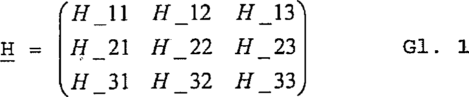
Die Vektoreinheit
Die Stromeinheit

Ist die Anzahl der zu berücksichtigenden spezifischen Temperaturbereiche und die Anzahl der zu berücksichtigenden Ruhephasen gleich und kann somit das Temperaturhistogramm mittels einer quadratischen Matrix dargestellt werden, kann der temperaturabhängige Selbstentladungsstrom ISD kann nach Gleichung Gl. 2 ermittelt werden. Kann das Temperaturhistogramm nicht mittels einer quadratischen Matrix dargestellt werden, da die Anzahl der spezifischen Temperaturbereiche und die Anzahl der Ruhephasen verschieden sind, kann der temperaturabhängige Selbstentladungsstrom ISD beispielsweise numerisch berechnet werden.If the number of specific temperature ranges to be considered and the number of quiescent phases to be taken into account are the same, and thus the temperature histogram can be represented by means of a square matrix, the temperature-dependent self-discharge current ISD can be calculated according to Eq. 2 are determined. If the temperature histogram can not be represented by means of a square matrix, since the number of specific temperature ranges and the number of rest periods are different, the temperature-dependent self-discharge current ISD can be numerically calculated, for example.
BezugszeichenlisteLIST OF REFERENCE NUMBERS
- 1010
- Energiespeicherenergy storage
- 100100
- Vorrichtung zum Betreiben eines EnergiespeichersDevice for operating an energy store
- 105105
- SignalaufbereitungseinheitSignal conditioning unit
- 110110
- LadezustandseinheitSOC unit
- 120120
- ZeitgebereinheitTimer unit
- 130130
- LadezustandsschätzerCharge state estimator
- 140140
- Integrationseinheitintegration unit
- 150150
- SummationseinheitSummation unit
- 160160
- erste Auswerteeinheitfirst evaluation unit
- 163163
- StromberechungseinheitStromberechungseinheit
- 190190
- zweite Auswerteeinheitsecond evaluation unit
- 191191
- Histogrammeinheithistogram unit
- 193193
- Vektoreinheitvector unit
- 195195
- Stromeinheitpower unit
- 200200
- Messeinheitmeasuring unit
- 300300
- TemperaturmesseinheitTemperature measurement unit
- HH
- Temperaturhistogramm-MatrixTemperature histogram matrix
- II
- zweite Betriebsgrößesecond farm size
- ISEISE
- SelbstentladungsstromSelf-discharge current
- ISDISD
- temperaturabhängiger Selbstentladungsstromtemperature-dependent self-discharge current
- SS
- Ladezustandsverlust-VektorSOC loss vector
- SOCSOC
- erster Ladezustandfirst charge state
- SOCiSoci
- zweiter Ladezustandsecond charge state
- tt
- RuhephasendauerDormancy period
- TempTemp
- EnergiespeichertemperaturEnergy storage temperature
- UU
- erste Betriebsgrößefirst farm size
- ΔSOC.DELTA.SOC
- LadezustandsverlustSOC loss
ZITATE ENTHALTEN IN DER BESCHREIBUNG QUOTES INCLUDE IN THE DESCRIPTION
Diese Liste der vom Anmelder aufgeführten Dokumente wurde automatisiert erzeugt und ist ausschließlich zur besseren Information des Lesers aufgenommen. Die Liste ist nicht Bestandteil der deutschen Patent- bzw. Gebrauchsmusteranmeldung. Das DPMA übernimmt keinerlei Haftung für etwaige Fehler oder Auslassungen.This list of the documents listed by the applicant has been generated automatically and is included solely for the better information of the reader. The list is not part of the German patent or utility model application. The DPMA assumes no liability for any errors or omissions.
Zitierte Nicht-PatentliteraturCited non-patent literature
- S. H. Choi, J. Kim, Y. Yoon, Self-discharge analysis of LiCoCO2 for lithium batteries, Journal of Power Sources 138 (2004), Seite 283 bis 287 [0003] SH Choi, J. Kim, Y. Yoon, Self-discharge analysis of LiCoCO 2 for lithium batteries, Journal of Power Sources 138 (2004), pages 283 to 287 [0003]
Claims (10)
Priority Applications (1)
| Application Number | Priority Date | Filing Date | Title |
|---|---|---|---|
| DE102010003421.5A DE102010003421B4 (en) | 2010-03-30 | 2010-03-30 | Method and device for operating an energy store |
Applications Claiming Priority (1)
| Application Number | Priority Date | Filing Date | Title |
|---|---|---|---|
| DE102010003421.5A DE102010003421B4 (en) | 2010-03-30 | 2010-03-30 | Method and device for operating an energy store |
Publications (2)
| Publication Number | Publication Date |
|---|---|
| DE102010003421A1 true DE102010003421A1 (en) | 2011-10-06 |
| DE102010003421B4 DE102010003421B4 (en) | 2021-09-02 |
Family
ID=44649878
Family Applications (1)
| Application Number | Title | Priority Date | Filing Date |
|---|---|---|---|
| DE102010003421.5A Active DE102010003421B4 (en) | 2010-03-30 | 2010-03-30 | Method and device for operating an energy store |
Country Status (1)
| Country | Link |
|---|---|
| DE (1) | DE102010003421B4 (en) |
Cited By (3)
| Publication number | Priority date | Publication date | Assignee | Title |
|---|---|---|---|---|
| WO2017137317A1 (en) * | 2016-02-09 | 2017-08-17 | EKU Power Drives GmbH | Method for controlling a stationary hydraulic pump system, and corresponding controller and pump system |
| DE102017009448A1 (en) | 2017-10-11 | 2018-04-19 | Daimler Ag | Method for determining a self-discharge of a battery with at least one battery cell |
| CN110888074A (en) * | 2018-08-15 | 2020-03-17 | 上海汽车集团股份有限公司 | Voltage determination method and device for SOC initial value calculation |
Citations (3)
| Publication number | Priority date | Publication date | Assignee | Title |
|---|---|---|---|---|
| US5541489A (en) * | 1994-12-15 | 1996-07-30 | Intel Corporation | Smart battery power availability feature based on battery-specific characteristics |
| US5561362A (en) * | 1993-11-04 | 1996-10-01 | Mitsubishi Jidosha Kogyo Kabushiki Kaisha | Remaining capacity meter and detection method for electric vehicle battery |
| US6441586B1 (en) * | 2001-03-23 | 2002-08-27 | General Motors Corporation | State of charge prediction method and apparatus for a battery |
Family Cites Families (1)
| Publication number | Priority date | Publication date | Assignee | Title |
|---|---|---|---|---|
| US6789026B2 (en) | 2002-12-29 | 2004-09-07 | Texas Instruments Incorporated | Circuit and method for monitoring battery state of charge |
-
2010
- 2010-03-30 DE DE102010003421.5A patent/DE102010003421B4/en active Active
Patent Citations (3)
| Publication number | Priority date | Publication date | Assignee | Title |
|---|---|---|---|---|
| US5561362A (en) * | 1993-11-04 | 1996-10-01 | Mitsubishi Jidosha Kogyo Kabushiki Kaisha | Remaining capacity meter and detection method for electric vehicle battery |
| US5541489A (en) * | 1994-12-15 | 1996-07-30 | Intel Corporation | Smart battery power availability feature based on battery-specific characteristics |
| US6441586B1 (en) * | 2001-03-23 | 2002-08-27 | General Motors Corporation | State of charge prediction method and apparatus for a battery |
Non-Patent Citations (1)
| Title |
|---|
| S. H. Choi, J. Kim, Y. Yoon, Self-discharge analysis of LiCoCO2 for lithium batteries, Journal of Power Sources 138 (2004), Seite 283 bis 287 |
Cited By (5)
| Publication number | Priority date | Publication date | Assignee | Title |
|---|---|---|---|---|
| WO2017137317A1 (en) * | 2016-02-09 | 2017-08-17 | EKU Power Drives GmbH | Method for controlling a stationary hydraulic pump system, and corresponding controller and pump system |
| US10358989B2 (en) | 2016-02-09 | 2019-07-23 | EKU Power Drives GmbH | Method for controlling a hydraulic pumping system, and corresponding control device and pumping system |
| DE102017009448A1 (en) | 2017-10-11 | 2018-04-19 | Daimler Ag | Method for determining a self-discharge of a battery with at least one battery cell |
| CN110888074A (en) * | 2018-08-15 | 2020-03-17 | 上海汽车集团股份有限公司 | Voltage determination method and device for SOC initial value calculation |
| CN110888074B (en) * | 2018-08-15 | 2022-02-01 | 上海汽车集团股份有限公司 | Voltage determination method and device for SOC initial value calculation |
Also Published As
| Publication number | Publication date |
|---|---|
| DE102010003421B4 (en) | 2021-09-02 |
Similar Documents
| Publication | Publication Date | Title |
|---|---|---|
| DE102008037270B4 (en) | Method and device for managing the power flow of an electric power storage device | |
| DE102007061130B4 (en) | Method and device for monitoring an electrical energy storage device | |
| DE102005062148B4 (en) | Method for determining the operating state of an energy store for electrical energy | |
| DE112009001553T5 (en) | Method for battery capacity estimation | |
| DE102011119060A1 (en) | Dynamic estimation of battery capacity | |
| DE102009045526A1 (en) | Method for initialization and operation of a battery management system | |
| DE102015203461A1 (en) | SYSTEM AND METHOD FOR THE ASSESSMENT OF HEALTH CONDITION ON THE BASIS OF BATTERY MODEL PARAMETERS | |
| EP3610277B1 (en) | System and method for determining a status of a vehicle battery | |
| DE102018212545A1 (en) | Method for monitoring a state of a battery, monitoring device and motor vehicle | |
| DE102012010486A1 (en) | Method and device for evaluating a state of aging of a battery | |
| WO2015055400A1 (en) | Method and device for determining an open-circuit voltage profile of a vehicle battery, dependent on a state of charge | |
| DE102014220914B4 (en) | Method and device for determining an operating point-dependent resistance change factor and vehicle | |
| DE102010019128B4 (en) | Capacity determination of automotive batteries | |
| DE102013018405A1 (en) | Determination of the condition of a battery characteristic estimation parameters | |
| DE102010003421A1 (en) | Energy storage device operating method for e.g. hybrid car, involves determining initial sizes of energy storage voltage and current, determining two state of charge, and determining state of charge loss dependent on two state of charge | |
| DE102010044230A1 (en) | Direct current internal resistance determining method for lithium ion phosphate battery for vehicle, involves determining time period, where time points for determining resistance are provided apart from each other around determined period | |
| DE10316638A1 (en) | Method for recognizing acid coating in battery, determines first charge state value in battery load phase, based on estimation of rest voltage, followed by determining second charge state after load phase, based on measured rest voltage | |
| DE102018115284A1 (en) | METHOD FOR ESTIMATING A STATE OF AN ELECTRICAL ENERGY STORAGE SYSTEM, AND SYSTEM FOR DETERMINING A REMAINING CAPACITY OF AN ELECTRICAL ENERGY STORAGE SYSTEM | |
| DE102015015743B4 (en) | Method for determining a driving range of a motor vehicle and motor vehicle | |
| DE102010031050A1 (en) | Method for operating energy storage e.g. lithium ions battery, in e.g. motor car, involves determining prognosis error based on energy and model energy storage voltages, and determining current energy storage capacitance dependent on error | |
| DE102019126245A1 (en) | System and method for determining the functional status and / or health status of an electric battery | |
| DE112018004450T5 (en) | Deterioration amount estimator, energy storage system, deterioration amount estimation method, and computer program | |
| DE102016121630B4 (en) | METHOD AND DEVICE FOR STATE MONITORING OF A STARTER BATTERY OF A MOTOR VEHICLE | |
| DE102008062205A1 (en) | Battery state of charge identifying method for motor vehicle, involves determining current state of charge under consideration of impedance of battery, and using transient internal resistance of battery as impedance of battery | |
| DE102009058893A1 (en) | Method for monitoring charging condition of rechargeable battery in e.g. electric vehicle, involves determining charging condition value, and determining maximum value, minimum value or reference value from determined value |
Legal Events
| Date | Code | Title | Description |
|---|---|---|---|
| R163 | Identified publications notified | ||
| R012 | Request for examination validly filed | ||
| R012 | Request for examination validly filed |
Effective date: 20150127 |
|
| R016 | Response to examination communication | ||
| R018 | Grant decision by examination section/examining division | ||
| R020 | Patent grant now final |