DE102010015813A1 - Sensor arrangement for a calorimetric mass flowmeter - Google Patents
Sensor arrangement for a calorimetric mass flowmeter Download PDFInfo
- Publication number
- DE102010015813A1 DE102010015813A1 DE102010015813A DE102010015813A DE102010015813A1 DE 102010015813 A1 DE102010015813 A1 DE 102010015813A1 DE 102010015813 A DE102010015813 A DE 102010015813A DE 102010015813 A DE102010015813 A DE 102010015813A DE 102010015813 A1 DE102010015813 A1 DE 102010015813A1
- Authority
- DE
- Germany
- Prior art keywords
- probe
- measuring tube
- holder
- sensor arrangement
- probes
- Prior art date
- Legal status (The legal status is an assumption and is not a legal conclusion. Google has not performed a legal analysis and makes no representation as to the accuracy of the status listed.)
- Withdrawn
Links
Images


Classifications
-
- G—PHYSICS
- G01—MEASURING; TESTING
- G01F—MEASURING VOLUME, VOLUME FLOW, MASS FLOW OR LIQUID LEVEL; METERING BY VOLUME
- G01F1/00—Measuring the volume flow or mass flow of fluid or fluent solid material wherein the fluid passes through a meter in a continuous flow
- G01F1/68—Measuring the volume flow or mass flow of fluid or fluent solid material wherein the fluid passes through a meter in a continuous flow by using thermal effects
- G01F1/684—Structural arrangements; Mounting of elements, e.g. in relation to fluid flow
Abstract
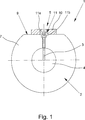
Beschrieben und dargestellt ist eine Sensoranordnung (1) für ein kalorimetrisches Massedurchflussmessgerät, zur Messung des Massedurchflusses in einem Messrohr (2), umfassend mindestens eine Sonde (3), wobei die Sonde (3) im Strömungsquerschnitt (4) des Messrohrs (2) positionierbar ist. Eine Sensoranordnung für ein kalorimetrisches Massedurchflussmessgerät, die zum einen eine gesteigerte Messgenauigkeit gewährleistet und zum anderen eine gesteigerte Flexibilität im Betrieb aufweist, wird realisiert, indem ein Halter (5) vorgesehen ist, wobei die Sonde (3) derart in dem Halter (5) befestigt ist, dass die Sonde (3) im Einbauzustand im Messrohr (2) im Wesentlichen berührungsfrei mit einem radialen Abstand durch mindestens eine Sondenausnehmung (6) in der Wand (7) des Messrohrs (2) in den Strömungsquerschnitt (3) des Messrohrs (2) geführt ist und wobei der Halter (5) derart ausgestaltet ist, dass die Sonde (3) von dem Messrohr (2) thermisch entkoppelt ist.A sensor arrangement (1) for a calorimetric mass flow meter, for measuring the mass flow in a measuring tube (2), is described and illustrated, comprising at least one probe (3), the probe (3) being positionable in the flow cross section (4) of the measuring tube (2) is. A sensor arrangement for a calorimetric mass flow meter, which on the one hand ensures increased measurement accuracy and on the other hand has increased flexibility in operation, is realized by providing a holder (5), the probe (3) being fastened in this way in the holder (5) is that the probe (3) in the installed state in the measuring tube (2) is essentially contact-free with a radial distance through at least one probe recess (6) in the wall (7) of the measuring tube (2) into the flow cross-section (3) of the measuring tube (2 ) and the holder (5) is designed in such a way that the probe (3) is thermally decoupled from the measuring tube (2).
Description
Die Erfindung betrifft eine Sensoranordnung für ein kalorimetrisches Massedurchflussmessgerät, zur Messung des Massedurchflusses in einem Messrohr, umfassend mindestens eine Sonde, wobei die Sonde im Strömungsquerschnitt des Messrohrs positionierbar ist.The invention relates to a sensor arrangement for a calorimetric mass flowmeter for measuring the mass flow in a measuring tube, comprising at least one probe, wherein the probe can be positioned in the flow cross section of the measuring tube.
Anordnungen zur kalorimetrischen Durchflussmessung sind in einer Vielzahl von Ausgestaltungen im Stand der Technik bekannt. Kalorimetrische Durchflussmesser dienen zur Bestimmung des Durchflusses von Fluiden, z. B. Flüssigkeiten oder Gase, in Rohrleitungen und eignen sich vorteilhaft zur Messung bei kleineren Strömungsgeschwindigkeiten. Die kalorimetrische Durchflussmessung eignet sich bevorzugt zur Bestimmung des Massedurchflusses, da dieser unmittelbar proportional zu dem Messsignal ist. Eine für die Bestimmung des Massendurchflusses wesentliche Messgröße ist der Wärmestrom Q ., der von einem geheizten Sensor an das strömende Fluid abgegeben und von dem Fluid abtransportiert wird. Dieser abtransportierte Wärmestrom entspricht der aufgewendeten elektrischen Heizleistung, die dann beispielsweise als Messgröße herangezogen wird. In der Praxis werden üblicherweise zwei Messmethoden unterschieden.Calorimetric flow measurement arrangements are known in a variety of prior art designs. Calorimetric flowmeters are used to determine the flow of fluids, eg. As liquids or gases, in pipelines and are advantageous for the measurement at lower flow rates. The calorimetric flow measurement is preferably suitable for determining the mass flow, since this is directly proportional to the measurement signal. One measure of importance for the determination of the mass flow rate is the heat flow Q., Which is emitted by a heated sensor to the flowing fluid and transported away from the fluid. This removed heat flow corresponds to the spent electric heating power, which is then used for example as a measured variable. In practice, two methods of measurement are usually distinguished.
Eine erste Methode ist die sogenannte Abkühlmethode, bei der das strömende Fluid die in den Strömungsquerschnitt des Messrohrs eingeführte geheizte Sonde abkühlt, wobei die Temperaturdifferenz zwischen der Temperatur des Fluids und der Sondentemperatur konstant gehalten wird. Bei der Abkühlmethode ist die für die konstante Temperaturdifferenz erforderliche Heizleistung das Maß zur Bestimmung des Massedurchflusses.A first method is the so-called cooling method, in which the flowing fluid cools the heated probe inserted into the flow cross-section of the measuring tube, the temperature difference between the temperature of the fluid and the probe temperature being kept constant. In the cooling method, the heating power required for the constant temperature difference is the measure for determining the mass flow.
Eine zweite Methode ist die sogenannte Aufwärmmethode, bei der der von der geheizten Sonde abgeführte Wärmestrom die Temperatur des Fluids an einer zweiten, stromabwärts positionierten Sonde erhöht, wobei die Temperaturerhöhung ΔT bei konstanter Heizleistung ein Maß zur Bestimmung des Massedurchflusses ist. Auch bei der zweiten Methode kann alternativ die Temperaturerhöhung ΔT durch Nachregeln der Heizleistung konstant gehalten werden, so dass dann die erforderliche Heizleistung als Messgröße für den Massestrom herangezogen werden kann.A second method is the so-called warm-up method in which the heat flow dissipated by the heated probe increases the temperature of the fluid at a second, downstream positioned probe, the temperature increase ΔT at constant heat output being a measure of mass flow. Also in the second method, alternatively, the temperature increase .DELTA.T be kept constant by readjusting the heating power, so that then the required heating power can be used as a measure of the mass flow.
Ein weiteres Unterscheidungsmerkmal für aus dem Stand der Technik bekannte kalorimetrische Massedurchflussmessgeräte ist die Positionierung der Sonde bzw. die Positionierung der Sonden. Je nach Messmethode sind beispielsweise zwei Sonden nebeneinander, orthogonal zur Strömungsrichtung angeordnet, wobei eine der beiden Sonden geheizt ist und die andere eine Referenztemperatur misst. Eine zweite Möglichkeit, die insbesondere für die Aufwärmmethode angewandt wird, beinhaltet, dass eine Sonde stromaufwärts und eine Sonde etwas weiter stromabwärts positioniert wird, wobei insbesondere die stromaufwärts positionierte Sonde geheizt wird und die stromabwärts positionierte Sonde die Temperaturerhöhung des strömenden Fluids misst. Alternativ dazu kann die Anordnung der geheizten und ungeheizten Sonde im Bezug auf die Strömungsrichtung auch umgekehrt sein, wobei dann die stromaufwärts angeordnete Sonde die Referenztemperatur misst und die stromabwärts positionierte Sonde eine Heizleistung an das strömende Medium abgibt.Another distinguishing feature of calorimetric mass flowmeters known from the prior art is the positioning of the probe or the positioning of the probes. Depending on the measuring method, for example, two probes are arranged side by side, orthogonal to the flow direction, wherein one of the two probes is heated and the other measures a reference temperature. A second option, which is particularly applied to the warm-up method, involves positioning a probe upstream and a probe slightly further downstream, in particular heating the upstream positioned probe and the downstream positioned probe measuring the temperature increase of the flowing fluid. Alternatively, the arrangement of the heated and unheated probes with respect to the flow direction may also be reversed, in which case the upstream probe measures the reference temperature and the downstream positioned probe emits a heating power to the flowing medium.
Im Stand der Technik ist bekannt, dass die Befestigung der Sonden am Messrohr durch Gewindestutzen erfolgt, in die die Sonden einschraubbar sind und so im Strömungsquerschnitt positioniert werden. Das Einschrauben der Sonden in die üblicherweise stoffschlüssig mit dem Messrohr verbundenen Stutzen bietet den Vorteil, dass die Sonden beispielweise zu Wartungszwecken einfach entfernt werden können. Nachteilig ist allerdings, dass die Sonden und der Stutzen unmittelbar aufeinander abgestimmt sein müssen, wodurch die Flexibilität im Betrieb, beispielweise beim Auswechseln einer Sonde, eingeschränkt ist. Die aus dem Stand der Technik bekannten Sensoranordnungen weisen ferner den Nachteil auf, dass durch Wärmeübergang zwischen den Sonden und dein Messrohr eine Beeinflussung des abgegebenen Wärmestroms bzw. der gemessenen Temperatur erfolgt, wodurch die Messergebnisse verfälscht werden und die Qualität der Messergebnisse reduziert wird.It is known in the prior art that the attachment of the probes to the measuring tube is effected by threaded connectors into which the probes can be screwed and thus positioned in the flow cross-section. The screwing of the probes in the usually materially connected to the measuring tube connecting piece has the advantage that the probes can be easily removed, for example, for maintenance purposes. The disadvantage, however, that the probes and the nozzle must be matched directly to each other, whereby the flexibility in operation, for example, when replacing a probe is limited. The known from the prior art sensor arrangements also have the disadvantage that effected by heat transfer between the probes and your measuring tube influencing the heat flow or the measured temperature, whereby the measurement results are falsified and the quality of the measurement results is reduced.
Ausgehend von den aus dem Stand der Technik bekannten Problemen, liegt der vorliegenden Erfindung die Aufgabe zugrunde, eine Sensoranordnung für ein kalorimetrisches Massedurchflussmessgerät anzugeben, die zum einen gesteigerte Messgenauigkeit gewährleistet und zum anderen eine gesteigerte Flexibilität im Betrieb aufweist.Based on the known from the prior art problems, the present invention has for its object to provide a sensor arrangement for a calorimetric mass flowmeter, which ensures on the one hand increased accuracy and on the other hand has increased flexibility in operation.
Die vorgenannte Aufgabe ist bei einer gattungsgemäßen Sensoranordnung dadurch gelöst, dass ein Halter vorgesehen ist, wobei die Sonde derart in dem Halter befestigt ist, dass die Sonde im Einbauzustand im Messrohr im Wesentlichen berührungsfrei mit einem radialen Abstand durch mindestens eine Sondenausnehmung in der Wand des Messrohrs in den Strömungsquerschnitt des Messrohrs geführt ist und wobei der Halter derart ausgestaltet ist, dass die Sonde von dem Messrohr thermisch entkoppelt ist.The above object is achieved in a generic sensor arrangement in that a holder is provided, wherein the probe is mounted in the holder such that the probe in the installed state in the measuring tube substantially non-contact with a radial distance by at least one probe recess in the wall of the measuring tube is guided in the flow cross-section of the measuring tube and wherein the holder is configured such that the probe is thermally decoupled from the measuring tube.
Die erfindungsgemäße Sensoranordnung weist den Vorteil auf, dass kein oder nur ein sehr geringer Wärmefluss von der Sonde auf die Wand des Messrohrs bzw. von der Wand des Messrohrs auf die Sonde erfolgen kann, da die Sonde von der Wand des Messrohres thermisch entkoppelt ist. Die Sonde ist auf der Außenseite des Messrohrs in dem Halter befestigt und ist durch eine Sondenausnehmung in der Wand des Messrohres in den Strömungsquerschnitt des Messrohrs hineingeführt. Die Sonde ist dabei derart in der Sondenausnehmung positioniert, dass sie die Wand des Messrohrs nicht berührt und keinerlei direkten Kontakt hat, wobei der radiale Abstand zwischen der Sonde und der Wand des Messrohrs sehr gering sein kann. Die Sonde ist vorzugsweise durch den Halter in ihrer Längsrichtung so angeordnet, dass ihre Spitze exakt in der Mittelachse des Strömungsquerschnitts des Messrohrs positioniert ist, wodurch sich ein optimales Messergebnis erzielen lässt.The sensor arrangement according to the invention has the advantage that no or only a very small heat flow from the probe to the wall of the measuring tube or from the wall of the measuring tube on the Probe can be made because the probe is thermally decoupled from the wall of the measuring tube. The probe is mounted on the outside of the measuring tube in the holder and is guided through a probe recess in the wall of the measuring tube in the flow cross-section of the measuring tube. The probe is positioned in the probe recess so that it does not touch the wall of the measuring tube and has no direct contact, wherein the radial distance between the probe and the wall of the measuring tube can be very small. The probe is preferably arranged by the holder in its longitudinal direction so that its tip is positioned exactly in the central axis of the flow cross section of the measuring tube, whereby an optimal measurement result can be achieved.
Durch unterschiedlich ausgestaltete Halter, also beispielsweise durch Halter mit unterschiedlicher Dicke oder geometrischer Ausgestaltung, lässt sich die Positionierung der Sonde beeinflussen bzw. an unterschiedliche Betriebsbedingungen anpassen. So können beispielsweise Sonden mit unterschiedlicher Länge bei einem Messrohr mit konstantem Durchmesser verwendet werden, indem eine Positionierung über die Geometrie des Halters erfolgt. In Abhängigkeit vom Durchmesser der Sondenausnehmung lassen sich mit entsprechenden Haltern auch Sonden mit variierenden Durchmessern an dem Messrohr befestigen. Die Sonde ist ausschließlich in dem Halter befestigt, der eine thermische Entkopplung der Sonde gewährleistet, folglich einen Wärmefluss zwischen Sonde und der Wand des Messrohrs unterbindet bzw. minimiert.By differently configured holder, so for example by holders with different thickness or geometric design, the positioning of the probe can be influenced or adapted to different operating conditions. For example, probes of different lengths may be used on a constant diameter measuring tube by positioning over the geometry of the holder. Depending on the diameter of the probe recess, probes with varying diameters can also be fastened to the measuring tube with appropriate holders. The probe is fixed exclusively in the holder, which ensures thermal decoupling of the probe, thus suppressing or minimizing heat flow between the probe and the wall of the measuring tube.
Um ein Austreten des in dem Strömungsquerschnitt fließenden Mediums durch die Sondenausnehmung, insbesondere durch den Ringspalt, zu unterbinden, ist zwischen dem Halter und der Wand des Messrohrs vorzugsweise wenigstens eine Dichtung angeordnet.In order to prevent leakage of the medium flowing in the flow cross-section through the probe recess, in particular through the annular gap, preferably at least one seal is arranged between the holder and the wall of the measuring tube.
Um eine Messung der Referenztemperatur bei gleichen Randbedingungen zu gewährleisten, ist gemäß einer ersten Ausgestaltung vorgesehen, dass mindestens zwei Sonden in dem Halter befestigt sind, wobei eine erste Sonde zumindest in einem Kopfbereich aufheizbar ist und eine zweite Sonde zur Messung einer Temperatur geeignet ist. Die beiden Sonden sind dabei in Abhängigkeit der gewählten Auswertemethode entweder nebeneinander oder hintereinander im Strömungskanal angeordnet, wobei die aufheizbare Sonde wiederum in Abhängigkeit von der Messmethode entweder stromabwärts oder stromaufwärts zur messenden Sonde angeordnet ist.In order to ensure a measurement of the reference temperature under the same boundary conditions, it is provided according to a first embodiment that at least two probes are mounted in the holder, wherein a first probe is heatable at least in a head region and a second probe is suitable for measuring a temperature. The two probes are arranged either side by side or one behind the other in the flow channel depending on the selected evaluation method, wherein the heatable probe is again arranged depending on the measuring method, either downstream or upstream of the measuring probe.
Für jede Sonde ist im Messrohr eine separate Sondenausnehmung vorgesehen, durch die die jeweilige Sonde in den Strömungsquerschnitt des Messrohrs hineingeführt ist, ohne dass die Sonde die Wand der Sondenausnehmung bzw. des Messrohrs dabei berührt. Beide Sonden sind in einem einzigen gemeinsamen Halter befestigt, so dass durch den Halter bzw. auch durch die Sondenausnehmungen die Relativposition der beiden Sonden im Strömungskanal festgelegt ist. Der Halter entkoppelt die beiden Sonden thermisch untereinander und entkoppelt auch die beiden Sonden thermisch von dem Messrohr.For each probe, a separate probe recess is provided in the measuring tube, through which the respective probe is guided into the flow cross-section of the measuring tube without the probe touching the wall of the probe recess or of the measuring tube. Both probes are mounted in a single common holder, so that the relative position of the two probes in the flow channel is determined by the holder or by the probe recesses. The holder thermally decouples the two probes from one another and also thermally decouples the two probes from the measuring tube.
Eine erste der beiden Sonden ist zumindest in einem Kopfbereich aufheizbar, so dass die Sonde im Kopfbereich einen Wärmestrom an das sie umströmende Fluid abgibt. Je nach Anwendungsfall ist allerdings auch vorgesehen, dass die Sonde nicht nur lediglich in ihrem Kopfbereich aufheizbar ist, sondern in einem größeren Teilbereich oder sogar über die gesamte Länge aufheizbar ist.A first of the two probes can be heated at least in a head region, so that the probe emits a heat flow in the head region to the fluid flowing around it. Depending on the application, however, it is also provided that the probe is not only heatable only in its head area, but is heatable in a larger portion or even over the entire length.
Die zweite der beiden Sonden dient zur Messung einer Referenztemperatur, beispielsweise der Fluidtemperatur, und ist beispielsweise mit einem Temperaturmesswiderstand oder einem Thermoelement ausgestattet.The second of the two probes is used to measure a reference temperature, for example, the fluid temperature, and is equipped for example with a temperature measuring resistor or a thermocouple.
Üblicherweise haben die erste und die zweite Sonde jeweils die gleiche Länge, so dass sie eine gleiche Eindringtiefe in den Strömungsquerschnitt, vorzugsweise bis unmittelbar auf die Ebene der Mittelachse des Strömungsquerschnitts aufweisen. Die Wärmeleiteigenschaften der Sonden sind beispielsweise über ihre gesamte Länge im Wesentlichen homogen, wobei alternativ auch unterschiedliche Wärmeleiteigenschaften über die Längserstreckung der Sonden vorgesehen sind.Usually, the first and the second probe each have the same length, so that they have an equal penetration depth in the flow cross-section, preferably to directly on the plane of the central axis of the flow cross-section. The heat-conducting properties of the probes are substantially homogeneous over their entire length, for example, and alternatively different thermal conduction properties over the longitudinal extent of the probes are provided.
Zur dauerhaften Positionierung des Halters an dem Messrohr hat sich als vorteilhaft herausgestellt, wenn gemäß einer weiteren Ausgestaltung der Halter an der Außenfläche des Messrohrs befestigbar ist, insbesondere das Messrohr in einem Befestigungsbereich zur Befestigung des Halters eine Abflachung aufweist. Der Halter wird dazu beispielsweise mit Schrauben an der Wand des Messrohrs festgeschraubt, so dass eine stabile und zuverlässige Befestigung des Halters und eine sichere Positionierung der Sonden gewährleistet ist. Alternativ ist auch vorgesehen, dass der Halter selbst nicht unmittelbar an dem Messrohr befestigt ist, sondern durch ein Befestigungselement, das seinerseits an dem Messrohr befestigt ist, kraft- oder formschlüssig gehalten ist.For permanent positioning of the holder on the measuring tube has been found to be advantageous if, according to a further embodiment, the holder can be fastened to the outer surface of the measuring tube, in particular the measuring tube has a flattening in a fastening region for fastening the holder. The holder is screwed for example with screws to the wall of the measuring tube, so that a stable and reliable attachment of the holder and secure positioning of the probes is ensured. Alternatively, it is also provided that the holder itself is not directly attached to the measuring tube, but held by a fastening element, which in turn is attached to the measuring tube, non-positively or positively.
Da eine Befestigung des Halters auf der gewölbten Oberfläche des Messrohrs aufwendig ist, ist bevorzugt, wenn das Messrohr in einem Befestigungsbereich zur Befestigung des Halters abgeflacht ist, so dass eine ebene Fläche zur Befestigung des Halters zur Verfügung steht. Von dieser Befestigungsfläche erstreckt sich die Sondenausnehmung durch die Wand des Messrohrs in den Strömungsquerschnitt hinein, wobei die Sondenausnehmung vorzugsweise orthogonal zur ebenen Fläche des Befestigungsbereichs ausgerichtet ist. Durch den Befestigungsbereich wird die Wandstärke des Messrohrs partiell reduziert, wobei darauf zu achten ist, dass eine ausreichende Wandstärke für einen sicheren Betrieb des Massedurchflussmessgeräts verbleibt.Since an attachment of the holder on the curved surface of the measuring tube is expensive, it is preferred if the measuring tube is flattened in a mounting region for attachment of the holder, so that a flat surface for fixing the holder is available. From this mounting surface, the probe recess extends through the wall of the measuring tube in the Flow cross section into it, wherein the probe recess is preferably aligned orthogonal to the flat surface of the mounting portion. The mounting area will partially reduce the wall thickness of the meter tube, taking care to maintain sufficient wall thickness for safe operation of the mass flow meter.
Der Halter liegt vorzugsweise im Wesentlichen flächig auf der Befestigungsfläche auf und ist derart mit dem Messrohr in Kontakt, dass durch die Sondenausnehmung kein Fluid aus dem Messrohr nach außen treten kann. Als vorteilhaft hat sich dabei eine dichtende Verbindung herausgestellt.The holder is preferably substantially flat on the mounting surface and is in such contact with the measuring tube, that no fluid can pass out of the measuring tube through the probe recess to the outside. As advantageous while a sealing connection has been found.
Um die Positionierung der Sonde in der Sondenausnehmung zu vereinfachen, ist gemäß einer Weiterbildung vorgesehen, dass im Einbauzustand zumindest ein Teil des Halters teilweise in die Wand des Messrohrs hineinragt. Der Halter weist dazu eine Ausformung, z. B. eine zylindrische Ausformung, auf, die in eine korrespondierende Ausnehmung in der Wand des Messrohrs hineinragt. Vorzugsweise verläuft zentral in der Ausnehmung auch eine Durchgangsbohrung in dem Halter für die Sonde, wobei die Ausnehmung in der Wand des Messrohrs sich dabei vorzugsweise als Sondenausnehmung fortsetzt, so dass die Sonde im Bereich der Ausformung im Halter gehalten ist und durch die exakte Positionierung der Ausformung in der korrespondierenden Ausnehmung in der Wand des Messrohrs eine exakte Positionierung der Sonde innerhalb der Sondenausnehmung sichergestellt ist.In order to simplify the positioning of the probe in the probe recess, it is provided according to a development that, in the installed state, at least part of the holder projects partially into the wall of the measuring tube. The holder has a shaping, z. B. a cylindrical shape, which projects into a corresponding recess in the wall of the measuring tube. Preferably, a through hole in the holder for the probe also runs centrally in the recess, wherein the recess in the wall of the measuring tube preferably continues as a probe recess, so that the probe is held in the holder in the region of the molding and by the exact positioning of the molding in the corresponding recess in the wall of the measuring tube exact positioning of the probe is ensured within the probe recess.
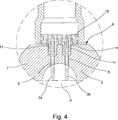
Gemäß einer weiteren vorteilhaften Ausgestaltung der Sensoranordnung ist vorgesehen, dass der Halter mehrteilig ausgestaltet ist, nämlich eine Basisplatte und eine der Anzahl der Sonden entsprechende Anzahl an Buchsen umfasst, insbesondere wobei die Buchsen zumindest teilweise formschlüssig in korrespondierende Buchsenausnehmungen in der Basisplatte einbringbar sind. Die Sonden sind dabei in den Buchsen befestigt, so dass die Buchsen mit den darin befestigten Sonden an der Basisplatte befestigbar sind. Vorzugsweise sind die Buchsen rotationssymmetrisch ausgestaltet, so dass sie in eine einfache kreisrunde Buchsenausnehmung in der Basisplatte einsteckbar sind. Vorzugsweise ist auch vorgesehen, dass die Außenkontur der Basisplatte rotationssymmetrisch ausgestaltet ist. Die Buchsen dienen folglich der Befestigung und Halterung der Sonde, wobei durch einen Austausch der Buchsen verschiedene Sonden mit unterschiedlichen Durchmessern in einer Basisplatte einsetzbar sind, wodurch die Sensoranordnung sehr variabel ist.According to a further advantageous embodiment of the sensor arrangement is provided that the holder is designed in several parts, namely a base plate and a number of probes corresponding number of sockets comprises, in particular wherein the sockets are at least partially positively inserted into corresponding Buchsenausnehmungen in the base plate. The probes are fastened in the bushings, so that the bushes with the probes fastened therein can be fastened to the base plate. Preferably, the sockets are designed rotationally symmetrical, so that they can be inserted into a simple circular Buchsenausnehmung in the base plate. Preferably, it is also provided that the outer contour of the base plate is configured rotationally symmetrical. The sockets thus serve to attach and hold the probe, whereby different probes with different diameters can be used in a base plate by replacing the sockets, whereby the sensor arrangement is very variable.
Um die Befestigung der Sonden noch zuverlässiger auszugestalten, insbesondere um durch die Strömung entstehende Vibrationen zu dämpfen, ist gemäß einer weiteren Ausgestaltung vorgesehen, dass die Buchsen zumindest teilweise in korrespondierende Ausnehmungen sowohl in der Basisplatte als auch in der Wand des Messrohrs einbringbar sind, so dass die Buchsen ein Verbindungsglied zwischen Basisplatte und der Wand des Messrohrs darstellen. Die Buchsen weisen dazu eine Durchgangsbohrung auf, die dem Außendurchmesser der verwendeten Sonden entspricht, so dass die Sonden zuverlässig in der Buchse fixiert werden können. Die zu der jeweiligen Buchse korrespondierende Ausnehmung in der Wand des Messrohres ist dabei vorzugsweise exakt koaxial zu der Sondenausnehmung positioniert bzw. setzt sich als Sondenausnehmung fort, so dass die Buchse eine exakte Positionierung der Sonde in der Sondenausnehmung gewährleistet.In order to make the attachment of the probes even more reliable, in particular to damp vibrations caused by the flow, it is provided according to a further embodiment that the bushes can be at least partially introduced into corresponding recesses in both the base plate and in the wall of the measuring tube, so that the bushes represent a link between the base plate and the wall of the measuring tube. The bushes have for this purpose a through hole, which corresponds to the outer diameter of the probes used, so that the probes can be reliably fixed in the socket. The corresponding recess in the wall of the measuring tube to the respective socket is preferably positioned exactly coaxial with the probe recess or continues as a probe recess, so that the sleeve ensures an exact positioning of the probe in the probe recess.
Die Buchse mit der darin befestigten Sonde ragt im Einbauzustand über die – vorzugsweise partiell abgeflachte – Außenkontur des Messrohrs hinaus, so dass auf die Buchse bzw. die Buchsen eine Basisplatte aufsetzbar ist, wodurch eine Fixierung der Buchsen durch die Basisplatte erfolgt. Die Buchse ragt dazu zumindest teilweise in eine korrespondierende Ausnehmung in der Basisplatte – eine Buchsenausnehmung – hinein, so dass eine formschlüssige Verbindung entsteht. Die Basisplatte selbst wird dabei beispielsweise mit einer Verschraubung an der Wand des Messrohrs befestigt oder durch ein Befestigungselement gehalten und liegt flächig an der – vorzugsweise abgeflachten – Außenfläche des Messrohrs an. Auch hier können durch einen Austausch der Buchsen unterschiedliche Sonden verwendet werden.The socket with the probe mounted therein protrudes in the installed state over the - preferably partially flattened - outer contour of the measuring tube, so that a base plate can be placed on the socket or sockets, whereby a fixation of the sockets is carried out by the base plate. The bush projects at least partially into a corresponding recess in the base plate - a Buchsenausnehmung - into, so that a positive connection is formed. In this case, the base plate itself is fastened to the wall of the measuring tube by means of a screw connection, for example, or held by a fastening element and rests flat against the outer surface of the measuring tube, which is preferably flattened. Again, different probes can be used by replacing the sockets.
Zur Gewährleistung einer thermischen Entkopplung der Sonden von der Wand des Messrohrs ist vorzugsweise vorgesehen, dass der Halter aus einem schlecht wärmeleitenden Material besteht, bevorzugt aus einem Kunststoff besteht, besonders bevorzugt aus Polyetheretherketon (PEEK) besteht. Ein Halter ist aus Kunststoff auf einfache Weise herzustellen und stellt aufgrund seiner schlechten Wärmeleitungseigenschaften eine optimale Isolierung der Sonde von der Wand des Messrohrs dar. Kunststoff hat zudem die vorteilhafte Eigenschaft, dass es schwingungsdämpfend wirkt, so dass der Halter die durch das strömende Medium entstehende Schwingung der Sonde dämpft. Der Halter kann beispielsweise als Spritzgussteil oder als im Wesentlichen rotationssymmetrisches Drehteil gefertigt werden. Als besonders vorteilhafter Kunststoff hat sich dabei Polyetheretherketon erwiesen. Als weitere Materialien für den Halter können aber beispielsweise auch Keramiken verwendet werden.To ensure thermal decoupling of the probes from the wall of the measuring tube, it is preferably provided that the holder consists of a poorly heat-conducting material, preferably consists of a plastic, particularly preferably consists of polyetheretherketone (PEEK). A holder is made of plastic in a simple manner and is due to its poor heat conduction properties optimal isolation of the probe from the wall of the measuring tube. Plastic also has the advantageous property that it acts vibration damping, so that the holder, the vibration generated by the flowing medium the probe attenuates. The holder can be made, for example, as an injection molded part or as a substantially rotationally symmetrical rotary part. In this case, polyetheretherketone has proven to be a particularly advantageous plastic. As further materials for the holder but also ceramics can be used for example.
Für eine explosionsgeschützte Variante der Sensoranordnung hat es sich als vorteilhaft herausgestellt, wenn der Halter aus einem elektrisch leitfähigen Material besteht, insbesondere aus einem leitfähigen Kunststoff besteht. Diese Ausgestaltung hat den Vorteil, dass zum einen keine unterschiedlichen elektrischen Potentiale zwischen dem Halter und der Wand des Messrohrs entstehen können, zum anderen hat die Verwendung von Kunststoff den Vorteil, dass gleichzeitig eine Schwingungsdämpfung erzielt wird. Elektrisch leitfähige Kunststoffe sind beispielsweise Kunststoffe, die mit leitenden Substanzen dotiert sind.For an explosion-proof variant of the sensor arrangement, it has proved to be advantageous if the holder consists of an electrically conductive material, in particular of a conductive plastic. This embodiment has the advantage that on the one hand no different electrical potentials between the holder and the wall of the measuring tube can arise, on the other hand, the use of plastic has the advantage that at the same time a vibration damping is achieved. Electrically conductive plastics are, for example, plastics doped with conductive substances.
Für eine zuverlässige Befestigung der Sonde an dem Halter ist bevorzugt vorgesehen, dass die Sonde in den Halter eingeklebt ist, insbesondere in die zu der jeweiligen Sonde korrespondierende Buchse eingeklebt ist. Die Sonde ist dadurch unverlierbar mit der Buchse verbunden und zuverlässig in dem Halter gehalten.For a reliable attachment of the probe to the holder is preferably provided that the probe is glued into the holder, in particular in the corresponding to the respective probe socket is glued. The probe is thereby captively connected to the socket and reliably held in the holder.
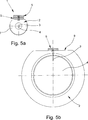
Gemäß einer letzten bevorzugten Ausgestaltung der Sensoranordnung ist vorgesehen, dass der Halter geometrisch derart ausgestaltet ist, dass eine Mehrzahl von Haltern übereinander formschlüssig stapelbar ist. Diese Ausgestaltung hat den Vorteil, dass ein einziger Sensortyp und ein einziger Haltertyp für unterschiedliche Messrohre mit verschiedenen Messrohrdurchmessern einsetzbar sind. Bei einem Messrohr mit einem großen Durchmesser wird beispielsweise nur ein einziger Halter benötigt, um den Sensor in dem Strömungskanal des Messrohrs zu positionieren. Bei einem Messrohr mit einem geringeren Durchmesser ist es dahingegen beispielsweise notwendig, dass eine Mehrzahl von Haltern übereinander gestapelt wird, so dass die Halter als Distanzstücke wirken und die Sonde mit einer einheitlichen Länge auch bei geringeren Messrohrdurchmessern verwendbar ist. Die Halter sind dabei derart ausgestaltet, dass die eigentlich für den Eingriff in die korrespondierende Ausnehmung in der Wand des Messrohrs vorgesehene Ausformung an dem Halter beim Stapeln exakt in eine dafür vorgesehene Ausnehmung eines zweiten Halters eingreifen kann, so dass eine beliebige Anzahl an Haltern übereinander stapelbar ist. Vorzugsweise werden jedoch zwei bis maximal drei Halter übereinander gestapelt.According to a last preferred embodiment of the sensor arrangement is provided that the holder is geometrically designed such that a plurality of holders one above the other is positively stackable. This embodiment has the advantage that a single sensor type and a single holder type can be used for different measuring tubes with different measuring tube diameters. For example, in the case of a measuring tube with a large diameter, only a single holder is required in order to position the sensor in the flow channel of the measuring tube. By contrast, in the case of a measuring tube with a smaller diameter, for example, it is necessary for a plurality of holders to be stacked on top of one another, so that the holders act as spacers and the probe with a uniform length can also be used with smaller measuring tube diameters. The holders are designed such that the actually intended for engagement in the corresponding recess in the wall of the measuring tube molding on the holder when stacking can engage exactly in a designated recess of a second holder, so that any number of holders stacked is. Preferably, however, two to a maximum of three holders are stacked on top of each other.
Im Einzelnen gibt es nun eine Vielzahl von Möglichkeiten, die erfindungsgemäße Sensoranordnung auszugestalten und weiterzubilden. Dazu wird verwiesen auf die dem Patentanspruch 1 nachgeordneten Patentansprüche sowie auf die Beschreibung von bevorzugten Ausführungsbeispielen in Verbindung mit der Zeichnung. In der Zeichnung zeigen:In particular, there are a variety of ways to design and further develop the sensor arrangement according to the invention. Reference is made to the claims subordinate to claim 1 and to the description of preferred embodiments in conjunction with the drawings. In the drawing show:
Eine Sensoranordnung gemäß der
Das Messrohr
Claims (11)
Priority Applications (5)
| Application Number | Priority Date | Filing Date | Title |
|---|---|---|---|
| DE102010015813A DE102010015813A1 (en) | 2010-04-20 | 2010-04-20 | Sensor arrangement for a calorimetric mass flowmeter |
| US12/956,346 US8544352B2 (en) | 2010-04-20 | 2010-11-30 | Sensor arrangement including a bracket for mounting a probe |
| EP11002965A EP2395329A3 (en) | 2010-04-20 | 2011-04-08 | Sensor assembly for a calorimetric throughput measuring device |
| JP2011094139A JP2011227083A (en) | 2010-04-20 | 2011-04-20 | Sensor arrangement for a calorimetric mass flowmeter |
| CN201110121424XA CN102288237A (en) | 2010-04-20 | 2011-04-20 | Sensor arrangement for a calorimetric mass flowmeter |
Applications Claiming Priority (1)
| Application Number | Priority Date | Filing Date | Title |
|---|---|---|---|
| DE102010015813A DE102010015813A1 (en) | 2010-04-20 | 2010-04-20 | Sensor arrangement for a calorimetric mass flowmeter |
Publications (1)
| Publication Number | Publication Date |
|---|---|
| DE102010015813A1 true DE102010015813A1 (en) | 2011-10-20 |
Family
ID=44358229
Family Applications (1)
| Application Number | Title | Priority Date | Filing Date |
|---|---|---|---|
| DE102010015813A Withdrawn DE102010015813A1 (en) | 2010-04-20 | 2010-04-20 | Sensor arrangement for a calorimetric mass flowmeter |
Country Status (5)
| Country | Link |
|---|---|
| US (1) | US8544352B2 (en) |
| EP (1) | EP2395329A3 (en) |
| JP (1) | JP2011227083A (en) |
| CN (1) | CN102288237A (en) |
| DE (1) | DE102010015813A1 (en) |
Cited By (3)
| Publication number | Priority date | Publication date | Assignee | Title |
|---|---|---|---|---|
| EP2887028A1 (en) | 2013-12-19 | 2015-06-24 | Krohne Messtechnik GmbH | Circuitry for temperature monitoring and calorimetric throughput measuring device |
| DE202016107242U1 (en) * | 2016-12-21 | 2018-03-22 | Nordson Corp. | Sensor device for determining a mass flow of a liquid hot melt adhesive |
| US11920984B2 (en) * | 2016-07-14 | 2024-03-05 | Mastrad | Wireless temperature probe |
Families Citing this family (11)
| Publication number | Priority date | Publication date | Assignee | Title |
|---|---|---|---|---|
| US8235592B2 (en) * | 2009-10-07 | 2012-08-07 | Wika Alexander Wiegand Se & Co. Kg | Gauge on a pipe section |
| KR101775257B1 (en) * | 2013-03-08 | 2017-09-05 | 가부시키가이샤 후지킨 | Fluid control device and structure for installing thermal sensor at fluid control device |
| US11181496B2 (en) | 2013-12-06 | 2021-11-23 | Pendotech | Sensor fitting for biotech process bag |
| US10041896B2 (en) | 2013-12-06 | 2018-08-07 | Pendo TECH | Sensor fitting for biotech process bag |
| US10557811B2 (en) | 2013-12-06 | 2020-02-11 | Pendotech | Sensor fitting for biotech process bag |
| US9874464B2 (en) | 2014-12-18 | 2018-01-23 | Wastequip, Llc | Sensor mount |
| DE102015116676A1 (en) * | 2015-01-20 | 2016-07-21 | Krohne Ag | Magnetic-inductive flowmeter and method for producing a measuring electrode |
| US20170108361A1 (en) * | 2015-10-18 | 2017-04-20 | Cdi Meters, Inc. | Target Flowmeter |
| DE102015118120A1 (en) * | 2015-10-23 | 2017-04-27 | Endress + Hauser Flowtec Ag | Thermal flow meter and assembly with a tube and the thermal flow meter |
| JP6793107B2 (en) * | 2017-11-27 | 2020-12-02 | 日立オートモティブシステムズ株式会社 | Flowmeter |
| US11067417B2 (en) | 2019-06-14 | 2021-07-20 | Rosemount Inc. | Averaging pitot tube having an adjustable resonant frequency |
Citations (6)
| Publication number | Priority date | Publication date | Assignee | Title |
|---|---|---|---|---|
| GB1219710A (en) * | 1969-06-18 | 1971-01-20 | Standard Telephones Cables Ltd | A fluid flowmeter |
| DE69410061T2 (en) * | 1993-11-10 | 1999-01-28 | Ksb Sa | Liquid measuring device |
| US5880365A (en) * | 1993-10-29 | 1999-03-09 | Sierra Instruments, Inc. | Thermal mass flow sensor |
| EP1074825A1 (en) * | 1999-08-06 | 2001-02-07 | Pgi International, Ltd | Temperature sensing device for metering fluids |
| US20030010808A1 (en) * | 2001-06-28 | 2003-01-16 | Uhland Scott A. | Methods for hermetically sealing microchip reservoir devices |
| DE202005013904U1 (en) * | 2005-09-02 | 2006-02-09 | Elb-Form Ges.m.b.H. | Pipe and sensor combination comprises pipe with flattened upper section, in which there is aperture with slots forming part of bayonet fitting, flange being mounted on sensor which carries male part of bayonet fitting |
Family Cites Families (17)
| Publication number | Priority date | Publication date | Assignee | Title |
|---|---|---|---|---|
| FR1419811A (en) | 1963-10-19 | 1965-12-03 | Device intended for automatically releasing automobile seat belts | |
| FR1410911A (en) * | 1964-10-09 | 1965-09-10 | Nat Inst For Res In Nuclear Sc | Apparatus for measuring mass flow |
| JPS601566B2 (en) * | 1979-10-17 | 1985-01-16 | 日産自動車株式会社 | Karman vortex flowmeter |
| DE3243098A1 (en) * | 1982-11-22 | 1984-05-24 | Rheinische Braunkohlenwerke AG, 5000 Köln | PROBE TUBLED INTO A REACTION CONTAINER FOR DETERMINING THE OPERATING CONDITION OF A MEDIUM |
| US4480467A (en) | 1982-11-29 | 1984-11-06 | Hyperion, Inc. | Flow monitoring device |
| DE3302080A1 (en) | 1983-01-22 | 1984-07-26 | Leybold-Heraeus GmbH, 5000 Köln | THERMAL MASS FLOW METER, ESPECIALLY FOR GASES |
| US4568874A (en) * | 1983-02-17 | 1986-02-04 | Drexelbrook Controls, Inc. | RF Admittance apparatus and method for monitoring the contents of a pipe |
| US4624146A (en) * | 1985-03-05 | 1986-11-25 | Onoda Cement Company, Ltd. | Flow rate measurement apparatus |
| US5437194A (en) * | 1991-03-18 | 1995-08-01 | Panametrics, Inc. | Ultrasonic transducer system with temporal crosstalk isolation |
| US5257532A (en) * | 1992-06-29 | 1993-11-02 | Rutgers, The State University Of New Jersey | Method and apparatus for measuring moisture content as a function of thermal response |
| TW416003B (en) * | 1999-08-20 | 2000-12-21 | Inst Of Nuclear Energy Res Roc | Method and device for void fraction measurement and adverse output signal mitigation on pressure-base instruments |
| US6508134B1 (en) * | 1999-09-01 | 2003-01-21 | Murray F. Feller | Transit-time flow sensor-frequency mode |
| US6802217B2 (en) * | 2001-12-05 | 2004-10-12 | Cdi Meters, Inc. | Flowmeter for compressed-air distribution systems |
| DE10249543A1 (en) * | 2002-10-23 | 2004-05-06 | Endress + Hauser Flowtec Ag, Reinach | vortex |
| US6883389B2 (en) * | 2003-08-21 | 2005-04-26 | Eldridge Products, Inc. | Flow averaging tube and method of using same |
| DE202008011995U1 (en) | 2008-09-09 | 2008-11-13 | E.L.B. Füllstandsgeräte Bundschuh GmbH & Co. | Level measuring device |
| US20110048564A1 (en) * | 2009-08-25 | 2011-03-03 | Fluid Components International Llc | Fluid flow conditioner |
-
2010
- 2010-04-20 DE DE102010015813A patent/DE102010015813A1/en not_active Withdrawn
- 2010-11-30 US US12/956,346 patent/US8544352B2/en not_active Expired - Fee Related
-
2011
- 2011-04-08 EP EP11002965A patent/EP2395329A3/en not_active Withdrawn
- 2011-04-20 JP JP2011094139A patent/JP2011227083A/en not_active Withdrawn
- 2011-04-20 CN CN201110121424XA patent/CN102288237A/en active Pending
Patent Citations (6)
| Publication number | Priority date | Publication date | Assignee | Title |
|---|---|---|---|---|
| GB1219710A (en) * | 1969-06-18 | 1971-01-20 | Standard Telephones Cables Ltd | A fluid flowmeter |
| US5880365A (en) * | 1993-10-29 | 1999-03-09 | Sierra Instruments, Inc. | Thermal mass flow sensor |
| DE69410061T2 (en) * | 1993-11-10 | 1999-01-28 | Ksb Sa | Liquid measuring device |
| EP1074825A1 (en) * | 1999-08-06 | 2001-02-07 | Pgi International, Ltd | Temperature sensing device for metering fluids |
| US20030010808A1 (en) * | 2001-06-28 | 2003-01-16 | Uhland Scott A. | Methods for hermetically sealing microchip reservoir devices |
| DE202005013904U1 (en) * | 2005-09-02 | 2006-02-09 | Elb-Form Ges.m.b.H. | Pipe and sensor combination comprises pipe with flattened upper section, in which there is aperture with slots forming part of bayonet fitting, flange being mounted on sensor which carries male part of bayonet fitting |
Cited By (4)
| Publication number | Priority date | Publication date | Assignee | Title |
|---|---|---|---|---|
| EP2887028A1 (en) | 2013-12-19 | 2015-06-24 | Krohne Messtechnik GmbH | Circuitry for temperature monitoring and calorimetric throughput measuring device |
| US11920984B2 (en) * | 2016-07-14 | 2024-03-05 | Mastrad | Wireless temperature probe |
| DE202016107242U1 (en) * | 2016-12-21 | 2018-03-22 | Nordson Corp. | Sensor device for determining a mass flow of a liquid hot melt adhesive |
| US10337898B2 (en) | 2016-12-21 | 2019-07-02 | Nordson Corporation | Sensor unit for measuring a mass flow rate of a liquid hot-melt adhesive |
Also Published As
| Publication number | Publication date |
|---|---|
| US8544352B2 (en) | 2013-10-01 |
| JP2011227083A (en) | 2011-11-10 |
| US20110252881A1 (en) | 2011-10-20 |
| CN102288237A (en) | 2011-12-21 |
| EP2395329A3 (en) | 2012-05-02 |
| EP2395329A2 (en) | 2011-12-14 |
Similar Documents
| Publication | Publication Date | Title |
|---|---|---|
| DE102010015813A1 (en) | Sensor arrangement for a calorimetric mass flowmeter | |
| DE102015114047B4 (en) | Heated flow conditioning systems and methods of use | |
| DE102008015359A1 (en) | Temperature sensor and method for its production | |
| EP2000787B1 (en) | Device for attaching a sensor to a tube | |
| EP3237851B1 (en) | Thermal type flowmeter | |
| EP2491353B1 (en) | Method for detecting the flow rate and flow direction of a fluid, and thermal-type flow meter | |
| DE3341860A1 (en) | MEASURING COUPLING FOR FLUIDIC SYSTEMS | |
| DE102010040285A1 (en) | Thermal flowmeter | |
| EP2553413B1 (en) | Measuring probe having a housing | |
| CH665286A5 (en) | HEAT METER. | |
| EP3899440B1 (en) | Magnetic inductive flow sensor and measurement point | |
| EP2378255B1 (en) | Calibration device for flow meters | |
| DE102012111058A1 (en) | Sensor and flowmeter | |
| DE19512111A1 (en) | Heat transfer control and / or measuring device | |
| DE102017128953B4 (en) | Measuring unit for recording dynamic parameters and / or physical properties of flowing media, preferably of flowing fluids | |
| EP2132533B1 (en) | Thermal mass flow rate device with sound elimination | |
| DE202010013086U1 (en) | Calibrator insert and calibrator with calibrator insert | |
| DE102008002871B4 (en) | measuring arrangement | |
| EP0309738A1 (en) | Electrically regulated mixing valve | |
| DE102012019433A1 (en) | Device for determining a characteristic of a medium | |
| DE102013006397A1 (en) | Method for operating thermal flow meter for determining flow of fluid medium through pipeline, involves combining media independent measurement of volume flow of fluid medium and time-dependent thermal conductivity measurement | |
| EP4052004A1 (en) | Non-invasive thermometer | |
| DE102013109217B4 (en) | Measuring probe for measuring electrical conductivity in low-conductivity liquids | |
| DE102011089942A1 (en) | Receiving device for measuring insert, has mold portion for fastening receiving device to pipeline, where mold portion has bore, in which component is inserted from end of bore | |
| DE102007027252B4 (en) | Device for determining mass flows of gaseous media through a radiator of a motor vehicle |
Legal Events
| Date | Code | Title | Description |
|---|---|---|---|
| R016 | Response to examination communication | ||
| R016 | Response to examination communication | ||
| R120 | Application withdrawn or ip right abandoned | ||
| R120 | Application withdrawn or ip right abandoned |
Effective date: 20140131 |