DE102010044746A1 - Implant for influencing the blood flow in arteriovenous malformations - Google Patents
Implant for influencing the blood flow in arteriovenous malformations Download PDFInfo
- Publication number
- DE102010044746A1 DE102010044746A1 DE102010044746A DE102010044746A DE102010044746A1 DE 102010044746 A1 DE102010044746 A1 DE 102010044746A1 DE 102010044746 A DE102010044746 A DE 102010044746A DE 102010044746 A DE102010044746 A DE 102010044746A DE 102010044746 A1 DE102010044746 A1 DE 102010044746A1
- Authority
- DE
- Germany
- Prior art keywords
- implant
- filaments
- proximal
- proximal end
- filament
- Prior art date
- Legal status (The legal status is an assumption and is not a legal conclusion. Google has not performed a legal analysis and makes no representation as to the accuracy of the status listed.)
- Pending
Links
Images


Classifications
-
- A—HUMAN NECESSITIES
- A61—MEDICAL OR VETERINARY SCIENCE; HYGIENE
- A61F—FILTERS IMPLANTABLE INTO BLOOD VESSELS; PROSTHESES; DEVICES PROVIDING PATENCY TO, OR PREVENTING COLLAPSING OF, TUBULAR STRUCTURES OF THE BODY, e.g. STENTS; ORTHOPAEDIC, NURSING OR CONTRACEPTIVE DEVICES; FOMENTATION; TREATMENT OR PROTECTION OF EYES OR EARS; BANDAGES, DRESSINGS OR ABSORBENT PADS; FIRST-AID KITS
- A61F2/00—Filters implantable into blood vessels; Prostheses, i.e. artificial substitutes or replacements for parts of the body; Appliances for connecting them with the body; Devices providing patency to, or preventing collapsing of, tubular structures of the body, e.g. stents
- A61F2/02—Prostheses implantable into the body
- A61F2/04—Hollow or tubular parts of organs, e.g. bladders, tracheae, bronchi or bile ducts
- A61F2/06—Blood vessels
- A61F2/07—Stent-grafts
-
- A—HUMAN NECESSITIES
- A61—MEDICAL OR VETERINARY SCIENCE; HYGIENE
- A61F—FILTERS IMPLANTABLE INTO BLOOD VESSELS; PROSTHESES; DEVICES PROVIDING PATENCY TO, OR PREVENTING COLLAPSING OF, TUBULAR STRUCTURES OF THE BODY, e.g. STENTS; ORTHOPAEDIC, NURSING OR CONTRACEPTIVE DEVICES; FOMENTATION; TREATMENT OR PROTECTION OF EYES OR EARS; BANDAGES, DRESSINGS OR ABSORBENT PADS; FIRST-AID KITS
- A61F2/00—Filters implantable into blood vessels; Prostheses, i.e. artificial substitutes or replacements for parts of the body; Appliances for connecting them with the body; Devices providing patency to, or preventing collapsing of, tubular structures of the body, e.g. stents
- A61F2/82—Devices providing patency to, or preventing collapsing of, tubular structures of the body, e.g. stents
- A61F2/86—Stents in a form characterised by the wire-like elements; Stents in the form characterised by a net-like or mesh-like structure
- A61F2/90—Stents in a form characterised by the wire-like elements; Stents in the form characterised by a net-like or mesh-like structure characterised by a net-like or mesh-like structure
-
- A—HUMAN NECESSITIES
- A61—MEDICAL OR VETERINARY SCIENCE; HYGIENE
- A61F—FILTERS IMPLANTABLE INTO BLOOD VESSELS; PROSTHESES; DEVICES PROVIDING PATENCY TO, OR PREVENTING COLLAPSING OF, TUBULAR STRUCTURES OF THE BODY, e.g. STENTS; ORTHOPAEDIC, NURSING OR CONTRACEPTIVE DEVICES; FOMENTATION; TREATMENT OR PROTECTION OF EYES OR EARS; BANDAGES, DRESSINGS OR ABSORBENT PADS; FIRST-AID KITS
- A61F2/00—Filters implantable into blood vessels; Prostheses, i.e. artificial substitutes or replacements for parts of the body; Appliances for connecting them with the body; Devices providing patency to, or preventing collapsing of, tubular structures of the body, e.g. stents
- A61F2/95—Instruments specially adapted for placement or removal of stents or stent-grafts
-
- D—TEXTILES; PAPER
- D04—BRAIDING; LACE-MAKING; KNITTING; TRIMMINGS; NON-WOVEN FABRICS
- D04C—BRAIDING OR MANUFACTURE OF LACE, INCLUDING BOBBIN-NET OR CARBONISED LACE; BRAIDING MACHINES; BRAID; LACE
- D04C1/00—Braid or lace, e.g. pillow-lace; Processes for the manufacture thereof
- D04C1/06—Braid or lace serving particular purposes
-
- A—HUMAN NECESSITIES
- A61—MEDICAL OR VETERINARY SCIENCE; HYGIENE
- A61F—FILTERS IMPLANTABLE INTO BLOOD VESSELS; PROSTHESES; DEVICES PROVIDING PATENCY TO, OR PREVENTING COLLAPSING OF, TUBULAR STRUCTURES OF THE BODY, e.g. STENTS; ORTHOPAEDIC, NURSING OR CONTRACEPTIVE DEVICES; FOMENTATION; TREATMENT OR PROTECTION OF EYES OR EARS; BANDAGES, DRESSINGS OR ABSORBENT PADS; FIRST-AID KITS
- A61F2/00—Filters implantable into blood vessels; Prostheses, i.e. artificial substitutes or replacements for parts of the body; Appliances for connecting them with the body; Devices providing patency to, or preventing collapsing of, tubular structures of the body, e.g. stents
- A61F2/82—Devices providing patency to, or preventing collapsing of, tubular structures of the body, e.g. stents
- A61F2002/823—Stents, different from stent-grafts, adapted to cover an aneurysm
-
- A—HUMAN NECESSITIES
- A61—MEDICAL OR VETERINARY SCIENCE; HYGIENE
- A61F—FILTERS IMPLANTABLE INTO BLOOD VESSELS; PROSTHESES; DEVICES PROVIDING PATENCY TO, OR PREVENTING COLLAPSING OF, TUBULAR STRUCTURES OF THE BODY, e.g. STENTS; ORTHOPAEDIC, NURSING OR CONTRACEPTIVE DEVICES; FOMENTATION; TREATMENT OR PROTECTION OF EYES OR EARS; BANDAGES, DRESSINGS OR ABSORBENT PADS; FIRST-AID KITS
- A61F2/00—Filters implantable into blood vessels; Prostheses, i.e. artificial substitutes or replacements for parts of the body; Appliances for connecting them with the body; Devices providing patency to, or preventing collapsing of, tubular structures of the body, e.g. stents
- A61F2/95—Instruments specially adapted for placement or removal of stents or stent-grafts
- A61F2002/9505—Instruments specially adapted for placement or removal of stents or stent-grafts having retaining means other than an outer sleeve, e.g. male-female connector between stent and instrument
-
- A—HUMAN NECESSITIES
- A61—MEDICAL OR VETERINARY SCIENCE; HYGIENE
- A61F—FILTERS IMPLANTABLE INTO BLOOD VESSELS; PROSTHESES; DEVICES PROVIDING PATENCY TO, OR PREVENTING COLLAPSING OF, TUBULAR STRUCTURES OF THE BODY, e.g. STENTS; ORTHOPAEDIC, NURSING OR CONTRACEPTIVE DEVICES; FOMENTATION; TREATMENT OR PROTECTION OF EYES OR EARS; BANDAGES, DRESSINGS OR ABSORBENT PADS; FIRST-AID KITS
- A61F2/00—Filters implantable into blood vessels; Prostheses, i.e. artificial substitutes or replacements for parts of the body; Appliances for connecting them with the body; Devices providing patency to, or preventing collapsing of, tubular structures of the body, e.g. stents
- A61F2/95—Instruments specially adapted for placement or removal of stents or stent-grafts
- A61F2/962—Instruments specially adapted for placement or removal of stents or stent-grafts having an outer sleeve
- A61F2/966—Instruments specially adapted for placement or removal of stents or stent-grafts having an outer sleeve with relative longitudinal movement between outer sleeve and prosthesis, e.g. using a push rod
- A61F2002/9665—Instruments specially adapted for placement or removal of stents or stent-grafts having an outer sleeve with relative longitudinal movement between outer sleeve and prosthesis, e.g. using a push rod with additional retaining means
-
- A—HUMAN NECESSITIES
- A61—MEDICAL OR VETERINARY SCIENCE; HYGIENE
- A61F—FILTERS IMPLANTABLE INTO BLOOD VESSELS; PROSTHESES; DEVICES PROVIDING PATENCY TO, OR PREVENTING COLLAPSING OF, TUBULAR STRUCTURES OF THE BODY, e.g. STENTS; ORTHOPAEDIC, NURSING OR CONTRACEPTIVE DEVICES; FOMENTATION; TREATMENT OR PROTECTION OF EYES OR EARS; BANDAGES, DRESSINGS OR ABSORBENT PADS; FIRST-AID KITS
- A61F2220/00—Fixations or connections for prostheses classified in groups A61F2/00 - A61F2/26 or A61F2/82 or A61F9/00 or A61F11/00 or subgroups thereof
- A61F2220/0025—Connections or couplings between prosthetic parts, e.g. between modular parts; Connecting elements
- A61F2220/005—Connections or couplings between prosthetic parts, e.g. between modular parts; Connecting elements using adhesives
-
- A—HUMAN NECESSITIES
- A61—MEDICAL OR VETERINARY SCIENCE; HYGIENE
- A61F—FILTERS IMPLANTABLE INTO BLOOD VESSELS; PROSTHESES; DEVICES PROVIDING PATENCY TO, OR PREVENTING COLLAPSING OF, TUBULAR STRUCTURES OF THE BODY, e.g. STENTS; ORTHOPAEDIC, NURSING OR CONTRACEPTIVE DEVICES; FOMENTATION; TREATMENT OR PROTECTION OF EYES OR EARS; BANDAGES, DRESSINGS OR ABSORBENT PADS; FIRST-AID KITS
- A61F2220/00—Fixations or connections for prostheses classified in groups A61F2/00 - A61F2/26 or A61F2/82 or A61F9/00 or A61F11/00 or subgroups thereof
- A61F2220/0025—Connections or couplings between prosthetic parts, e.g. between modular parts; Connecting elements
- A61F2220/0058—Connections or couplings between prosthetic parts, e.g. between modular parts; Connecting elements soldered or brazed or welded
-
- A—HUMAN NECESSITIES
- A61—MEDICAL OR VETERINARY SCIENCE; HYGIENE
- A61F—FILTERS IMPLANTABLE INTO BLOOD VESSELS; PROSTHESES; DEVICES PROVIDING PATENCY TO, OR PREVENTING COLLAPSING OF, TUBULAR STRUCTURES OF THE BODY, e.g. STENTS; ORTHOPAEDIC, NURSING OR CONTRACEPTIVE DEVICES; FOMENTATION; TREATMENT OR PROTECTION OF EYES OR EARS; BANDAGES, DRESSINGS OR ABSORBENT PADS; FIRST-AID KITS
- A61F2250/00—Special features of prostheses classified in groups A61F2/00 - A61F2/26 or A61F2/82 or A61F9/00 or A61F11/00 or subgroups thereof
- A61F2250/0014—Special features of prostheses classified in groups A61F2/00 - A61F2/26 or A61F2/82 or A61F9/00 or A61F11/00 or subgroups thereof having different values of a given property or geometrical feature, e.g. mechanical property or material property, at different locations within the same prosthesis
- A61F2250/0043—Special features of prostheses classified in groups A61F2/00 - A61F2/26 or A61F2/82 or A61F9/00 or A61F11/00 or subgroups thereof having different values of a given property or geometrical feature, e.g. mechanical property or material property, at different locations within the same prosthesis differing in electric properties, e.g. in electrical conductivity, in galvanic properties
-
- D—TEXTILES; PAPER
- D10—INDEXING SCHEME ASSOCIATED WITH SUBLASSES OF SECTION D, RELATING TO TEXTILES
- D10B—INDEXING SCHEME ASSOCIATED WITH SUBLASSES OF SECTION D, RELATING TO TEXTILES
- D10B2509/00—Medical; Hygiene
- D10B2509/06—Vascular grafts; stents
Abstract
Die Erfindung betrifft ein Implantat (1) für Blutgefäße, insbesondere zur Beeinflussung des Blutflusses im Bereich arteriovenöser Fehlbildungen, mit einer Wandung aus einzelnen Filamenten (2), die zu einem im Wesentlichen röhrenförmigen Geflecht zusammengefasst sind, das sich in axialer Richtung von proximal nach distal erstreckt, wobei die einzelnen Filamente (2) sich gegenseitig kreuzen und miteinander Kreuzungspunkte (3) bilden, das Implantat (1) in der Weise verformbar ist, dass es in einem Einführungskatheter eine Form mit vermindertem Durchmesser annimmt und am Ort der Implantation unter Anpassung an den Blutgefäßdurchmesser expandiert, am proximalen und/oder distalen Ende des Geflechts die Filamentenden jeweils mindestens paarweise zusammengeführt und miteinander dauerhaft verbunden sind, wobei die miteinander verbundenen Filamentenden atraumatisch geformt sind, und wobei die sich kreuzenden Filamente (2) an den distal der Filamentenden liegenden Kreuzungspunkten (3) am proximalen Ende (10) des Implantats (1) jeweils direkt oder indirekt miteinander verbunden sind. Auf diese Weise wird gewährleistet, dass sich das Implantat (1) nach Freisetzung auch am proximalen Ende bis zu den Gefäßwänden hin ausdehnt und die Filamentenden nicht in das Gefäßlumen hineinstehen.The invention relates to an implant (1) for blood vessels, in particular for influencing the blood flow in the area of arteriovenous malformations, with a wall made of individual filaments (2), which are combined to form an essentially tubular braid that extends in the axial direction from proximal to distal extends, the individual filaments (2) crossing each other and forming points of intersection (3) with one another, the implant (1) being deformable in such a way that it takes on a shape with a reduced diameter in an insertion catheter and adjusts at the site of the implantation the blood vessel diameter expands, at the proximal and / or distal end of the braid the filament ends are each brought together at least in pairs and are permanently connected to one another, the connected filament ends being atraumatically shaped, and the crossing filaments (2) at the points of intersection located distal to the filament ends (3) a m proximal end (10) of the implant (1) are each directly or indirectly connected to each other. In this way it is ensured that the implant (1) also expands to the vessel walls at the proximal end after release and that the filament ends do not protrude into the vessel lumen.
Description
Die Erfindung betrifft ein Implantat für Blutgefäße, insbesondere zur Beeinflussung des Blutflusses im Bereich arteriovenöser Fehlbildungen, mit einer Wandung aus einzelnen Filamenten, die zu einem im Wesentlichen röhrenförmigen Geflecht zusammengefasst sind, das sich in axialer Richtung von proximal nach distal erstreckt, wobei die einzelnen Filamente sich gegenseitig kreuzen und miteinander Kreuzungspunkte bilden, das Implantat in der Weise verformbar ist, dass es in einem Einführungskatheter eine Form mit vermindertem Durchmesser annimmt und am Ort der Implantation unter Anpassung an den Blutgefäßdurchmesser expandiert, und am proximalen und/oder distalen Ende des Geflechts die Filamentenden jeweils mindestens paarweise zusammengeführt und miteinander dauerhaft verbunden sind, wobei die miteinander verbundenen Filamentenden atraumatisch geformt sind. Das Implantat ist insbesondere dazu bestimmt, den Blutfluss im Bereich von arteriovenösen Fehlbildungen, etwa Fisteln und Aneurysmen, zu beeinflussen. Es kann ferner auch zur Behandlung des ischämischen Schlaganfalls eingesetzt werden, etwa zur Wiederherstellung, Erhöhung oder Aufrechterhaltung des Blutflusses. Das Implantat kann rückholbar ausgelegt sein.The invention relates to an implant for blood vessels, in particular for influencing the blood flow in the region of arteriovenous malformations, with a wall of individual filaments, which are combined into a substantially tubular braid extending in the axial direction from proximal to distal, wherein the individual filaments cross each other and intersect with each other, the implant is deformable in such a way that it assumes a reduced diameter diameter in an insertion catheter and expands at the site of implantation in adaptation to the blood vessel diameter, and at the proximal and / or distal end of the mesh Filament ends are each brought together at least in pairs and permanently connected to each other, wherein the interconnected filament ends are atraumatisch. Specifically, the implant is designed to influence blood flow in the area of arteriovenous malformations, such as fistulas and aneurysms. It may also be used to treat ischemic stroke, such as to restore, increase or maintain blood flow. The implant can be designed to be retrievable.
Arteriovenöse Fehlbildungen können in einem Patienten zu erheblichen Beeinträchtigungen und Gefährdungen bis hin zum Tode führen. Dies gilt insbesondere auch für arteriovenöse Fisteln und Aneurysmen, insbesondere dann, wenn sie im zerebralen Bereich auftreten. In der Regel versucht man derartige Fehlbildungen durch Implantate zu verschließen. Derartige Implantate werden in der Regel auf endovaskulärem Weg mit Hilfe von Kathetern gesetzt.Arteriovenous malformations in a patient can lead to significant impairments and threats, including death. This is especially true for arteriovenous fistulas and aneurysms, especially if they occur in the cerebral area. As a rule, attempts are made to close such malformations by implants. Such implants are usually placed on the endovascular route with the help of catheters.
Insbesondere bei Aneurysmen hat sich die Implantierung von Platinspiralen bewährt, die das Aneurysma mehr oder weniger vollständig ausfüllen, den Bluteinstrom weitgehend blockieren und dazu führen, dass sich ein lokaler Thrombus ausbildet, der das Aneurysma ausfüllt und letztlich verschließt. Diese Behandlungsmethode ist allerdings nur bei Aneurysmen geeignet, die über einen relativ engen Zugang zum Gefäßsystem verfügen, sogenannte Beerenaneurysmen. Bei Aussackungen von Blutgefäßen, die über einen weiten Zugang zum Gefäß verfügen, drohen die implantierten Spiralen wieder ausgeschwemmt zu werden und Schäden in anderen Bereichen des Gefäßsystems herbeizuführen.Particularly in aneurysms, the implantation of platinum spirals has proved successful, which fill the aneurysm more or less completely, largely block the influx of blood and lead to the formation of a local thrombus, which fills the aneurysm and ultimately closes. However, this treatment method is only suitable for aneurysms that have a relatively narrow access to the vascular system, so-called berry aneurysms. In the case of bagging of blood vessels that have wide access to the vessel, the implanted coils may be flushed out again and cause damage in other areas of the vascular system.
In solchen Fällen wurde bereits vorgeschlagen, eine Art Stent zu setzen, der die Öffnung des Aneurysmas „vergittert” und dadurch die Ausschwemmung der Okklusionsspiralen verhindert. Derartige Stents, die über eine relativ weitmaschige Wandung verfügen, haben aber eine Reihe von Nachteilen.In such cases it has already been proposed to place a type of stent which "bars" the opening of the aneurysm and thereby prevents flushing out of the occlusion coils. Such stents, which have a relatively wide-meshed wall, but have a number of disadvantages.
Zum einen ist dies die weitmaschige Struktur, die den Blutzutritt in das Aneurysma unbeeinträchtigt zulässt. Ist das Aneurysma aber nicht hinreichend mit dem Okklusionsmittel ausgefüllt, bleibt der Druck auf die Gefäßwandung unvermindert bestehen. Eine Nachbehandlung ist aber unter diesen Umständen nur schwer möglich, da der Stent den Zugang zum Aneurysma beeinträchtigt und die Einbringung weiterer Okklusionsmittel behindert.On the one hand, this is the wide-meshed structure that allows blood access into the aneurysm unimpaired. However, if the aneurysm is not sufficiently filled with the occlusive agent, the pressure on the vessel wall remains undiminished. Postoperative care is difficult in these circumstances, as the stent impairs access to the aneurysm and obstructs the insertion of other occlusive agents.
Ein weiterer Nachteil ist die fehlende Anpassbarkeit des Stents an seinen Einsatzort. Für eine optimale Funktion sollte sich der Stent dicht an die Gefäßwandung anlegen, ohne jedoch einen übermäßigen Druck auf die Wandung auszuüben. Im Gegensatz zu Stents, die eine Aufweitung des Gefäßes bei Stenosen bewirken sollen, sind diese Stents eher als eine Art Manschette zu verstehen, die das Gefäßlumen und die Endothelwand des Gefäßes möglichst wenig beeinflussen soll. In der Folge sind diese Stents, selbst wenn sie für den Einsatzzweck speziell ausgewählt wurden, nur eingeschränkt an die Anforderungen angepasst.Another disadvantage is the lack of adaptability of the stent to its place of use. For optimal function, the stent should attach tightly to the vessel wall without exerting excessive pressure on the wall. In contrast to stents, which are intended to cause an expansion of the vessel in stenoses, these stents are to be understood rather as a kind of cuff, which should influence the vascular lumen and the endothelial wall of the vessel as little as possible. As a result, these stents, even if they have been specially selected for the purpose, are adapted only to a limited extent to the requirements.
Aus Drahtgeflecht bestehende Stents sind insbesondere für den Einsatz im koronaren Bereich seit langem bekannt. Diese Stents werden in der Regel als Rundgeflecht gefertigt, wobei die einzelnen Drahtfilamente in gegenläufigen spiralförmigen bzw. helixförmigen Lagen die Stentwandung ausbilden. Es entsteht ein Maschengeflecht, das in radialer Richtung sowohl abstützt als auch für Blut durchlässig ist.Made of wire mesh stents have long been known, especially for use in the coronary area. These stents are usually made as a round braid, wherein the individual wire filaments in opposing spiral or helical layers form the stent wall. The result is a mesh that is both supported in the radial direction and permeable to blood.
Ein Problem dieser als Rundgeflecht ausgebildeten Stents sind die an den freien Enden bestehenden losen Enden, die aufgrund ihres geringen Durchmessers, traumatisch wirken können.One problem with these round-brained stents is the loose ends at the free ends, which, because of their small diameter, can be traumatic.
Gemäß
Gemäß
Derartige als Rundgeflecht aus Filamenten bestehende Stents werden beim Einsatz zur Behandlung von Stenosen mit Hilfe eines Ballons am Einsatzort hydraulisch aufgeweitet und an der Gefäßwandung fixiert. Während der Einbringung dient der an einem Einführdraht befestigte Ballon als Transportvehikel, auf das der Stent aufgecrimpt ist. Ein solches Transportvehikel sollte aber für Implantate, die zur Beeinflussung bzw. Kanalisierung des Blutflusses im zerebralen Bereich dienen, nicht eingesetzt werden; vielmehr ist hier ein Implantat, das sich selbständig an den Gefäßdurchmesser anpasst und an die Gefäßwandung anlegt, von Vorteil. Such existing as a round braid of filaments stents are hydraulically expanded when used for the treatment of stenoses with the help of a balloon at the site and fixed to the vessel wall. During insertion, the balloon attached to an introducer wire serves as a delivery vehicle to which the stent is crimped. However, such a transport vehicle should not be used for implants that serve to influence or channel blood flow in the cerebral area; Rather, here is an implant that adapts itself to the vessel diameter and applies to the vessel wall, an advantage.
Ein weiteres Problem der aus Drahtgeflecht bestehenden Stents oder Implantate ist die Fertigung. Vorteilhaft ist die Fertigung als geflochtener Endlosschlauch, der auf die gewünschte Dimension abgelängt wird. Hierbei entstehen im Bereich der beiden Enden des abgelängten Schlauches lose Drahtenden, die aufwändig entschärft werden müssen, beispielsweise durch die oben erwähnten Verbindungsglieder.Another problem of the existing wire mesh stents or implants is the production. The production is advantageous as a braided endless tube, which is cut to the desired dimension. In the process, loose wire ends are created in the region of the two ends of the cut-to-length hose, which must be effortlessly defused, for example by the above-mentioned connecting links.
In der
Aus der
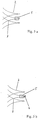
Bei all diesen Implantaten hat sich jedoch als Problem herausgestellt, dass sich die Filamentenden am proximalen Ende bei der Freisetzung des Implantats manchmal nicht in ausreichendem Maße zu den Gefäßwänden hin aufweiten. Dieser Effekt wird in der Literatur auch teilweise als „Fischmauleffekt” bezeichnet und ist u. a. darauf zurückzuführen, dass am proximalen Ende des Implantats geringere Radialkräfte wirken als am distalen Ende. Bei der Freisetzung wird zunächst die über dem Implantat liegende Abdeckung entfernt, so dass sich das distale Ende aufweiten kann, während das proximale Ende weiterhin mit dem Ablösemechanismus in Verbindung steht. Erst nach Freisetzung vom Ablösemechanismus kann auch das proximale Ende expandieren. Die Kräfte, die das proximale Ende radial nach außen drücken, sind hier jedoch geringer als am distalen Ende und im mittleren Bereich, weil die Expansion ohne zusätzliche Unterstützung erfolgen muss.In all of these implants, however, it has been found to be a problem that sometimes the filament ends at the proximal end do not expand sufficiently to the vessel walls upon release of the implant. This effect is also referred to in the literature as "fishmouth effect" and is u. a. due to the fact that lower radial forces act at the proximal end of the implant than at the distal end. Upon release, the cover overlying the implant is first removed so that the distal end can expand while the proximal end continues to communicate with the release mechanism. Only after release of the release mechanism, the proximal end can expand. However, the forces that press the proximal end radially outward are less here than at the distal end and in the middle region, because the expansion must be done without additional support.
Der Fischmauleffekt hat zur Folge, dass Filamentenden am proximalen Ende in das Gefäßlumen hineinragen und für eine Behinderung des Blutflusses sorgen. Das Implantat ist somit unter Umständen nicht in ausreichendem Maße atraumatisch. Weitere Interventionen, bei denen z. B. ein Katheter das Implantat passieren muss, werden erschwert oder behindert.The result of the fishmouth effect is that filament ends protrude into the vessel lumen at the proximal end and obstruct the blood flow. The implant may not be sufficiently atraumatic under certain circumstances. Further interventions, in which z. B. a catheter must pass the implant are difficult or hindered.
Die Erfindung hat sich zur Aufgabe gesetzt, ein Implantat der eingangs genannten Art zur Verfügung zu stellen, bei dem die radiale Aufweitung des Implantats am proximalen Ende sichergestellt ist.The invention has set itself the task of providing an implant of the type mentioned, in which the radial expansion of the implant is ensured at the proximal end.
Diese Aufgabe wird erfindungsgemäß gelöst durch ein Implantat für Blutgefäße, insbesondere zur Beeinflussung des Blutflusses im Bereich arteriovenöser Fehlbildungen, mit einer Wandung aus einzelnen Filamenten, die zu einem im Wesentlichen röhrenförmigen Geflecht zusammengefasst sind, das sich in axialer Richtung von proximal nach distal erstreckt, wobei die einzelnen Filamente sich gegenseitig kreuzen und miteinander Kreuzungspunkte bilden, das Implantat in der Weise verformbar ist, dass es in einem Einführungskatheter eine Form mit vermindertem Durchmesser annimmt und am Ort der Implantation unter Anpassung an den Blutgefäßdurchmesser expandiert, am proximalen und/oder distalen Ende des Geflechts die Filamentenden jeweils mindestens paarweise zusammengeführt und miteinander dauerhaft verbunden sind, wobei die miteinander verbundenen Filamentenden atraumatisch geformt sind, und wobei die sich kreuzenden Filamente an den distal der Filamentenden liegenden Kreuzungspunkten am proximalen Ende des Implantats jeweils direkt oder indirekt miteinander verbunden sind.This object is achieved by an implant for blood vessels, in particular for influencing the blood flow in the area of arteriovenöser malformations, with a wall of individual filaments, which are combined into a substantially tubular braid extending in the axial direction from proximal to distal, wherein the individual filaments cross each other and intersect each other, the implant is deformable in such a way that it assumes a reduced diameter diameter in an insertion catheter and expands at the site of implantation to accommodate the blood vessel diameter at the proximal and / or distal end of the implant Braid, the filament ends are each brought together at least in pairs and permanently connected to each other, wherein the interconnected filament ends are atraumatic, and wherein the intersecting filaments at the distal ends of the filament ends crossing points a m proximal end of the implant are each connected directly or indirectly.
Es hat sich herausgestellt, dass die gegenseitige Fixierung der Filamente aneinander im Bereich der Kreuzungspunkte am proximalen Ende dazu führt, dass sich das Implantat auch an diesem Ende in ausreichendem Maße radial aufweitet, so dass die Filamentenden eng an der Gefäßwand anliegen. Die mangelnde radiale Aufweitung der Filamente bei den beschriebenen Implantaten aus dem Stand der Technik wird u. a. darauf zurückgeführt, dass an den Kreuzungspunkten zwischen den Filamenten eine Reibung entsteht, die die Aufweitung behindert. Diese Reibung wird durch die gegenseitige Fixierung der Filamente im Bereich der Kreuzungspunkte unterbunden. Die Kreuzungspunkte werden vielmehr in einer bestimmten axialen Position relativ zum proximalen Ende des Implantats gehalten, so dass keine Verlagerung einzelner Kreuzungspunkte verbunden mit einer gegenseitigen Behinderung der Filamente bei der Aufweitung mehr auftritt.It has been found that the mutual fixation of the filaments to each other in the region of the crossing points at the proximal end results in the implant also expanding radially enough at this end, so that the filament ends fit snugly against the vessel wall. The lack of radial expansion of the filaments in the described implants of the prior art is u. a. attributed to the fact that at the intersections between the filaments a friction arises, which impedes the expansion. This friction is prevented by the mutual fixation of the filaments in the region of the crossing points. Rather, the points of intersection are held in a specific axial position relative to the proximal end of the implant, so that no displacement of individual intersection points associated with a mutual obstruction of the filaments in the expansion occurs more.
Unter den Kreuzungspunkten am proximalen Ende des Implantats werden die Kreuzungspunkte verstanden, an denen sich die Filamente zwar kreuzen, nicht aber die Filamentenden selbst, an denen die Filamente dauerhaft miteinander verbunden sind. Die proximal gelegenen Kreuzungspunkte liegen somit vom proximalen Filamentende aus gesehen geringfügig in Richtung distal. Erfindungsgemäß werden unter Kreuzungspunkten am proximalen Ende des Implantats die Kreuzungspunkte in den ersten drei orthogonal zur Längsrichtung des Implantats liegenden Kreuzungspunktebenen verstanden, d. h. die am weitesten proximal liegenden Kreuzungspunkte, die am zweitweitesten proximal liegenden Kreuzungspunkte und die am drittweitesten proximal liegenden Kreuzungspunkte. Bevorzugt sind zumindest die sich kreuzenden Filamente an den am weitesten proximal liegenden Kreuzungspunkten miteinander verbunden, es kann jedoch sinnvoll sein, auch die sich kreuzenden Filamente an den etwas weiter distal liegenden Kreuzungspunkten zu verbinden. Denkbar ist auch eine Verbindung von sich kreuzenden Filamenten an Kreuzungspunkten im distalen Bereich des Implantats. The crossing points at the proximal end of the implant are to be understood as meaning the crossing points at which the filaments intersect, but not the filament ends themselves, on which the filaments are permanently connected to one another. The proximal crossing points are thus slightly distal in direction from the proximal filament end. According to the invention, crossing points at the proximal end of the implant mean the crossing points in the first three crossing points lying orthogonal to the longitudinal direction of the implant, ie the most proximal crossing points, the second closest crossing points and the third most proximal crossing points. Preferably, at least the intersecting filaments are connected to each other at the most proximal crossing points, but it may be useful to connect the intersecting filaments at the crossing points located somewhat further distal. It is also conceivable to connect filaments crossing at intersection points in the distal region of the implant.
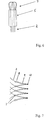
Die Verbindung der Filamente untereinander an den proximal gelegenen Kreuzungspunkten kann auf unterschiedliche Weise erfolgen. Eine Möglichkeit besteht darin, die Filamente durch Schlaufen zu führen, die durch separate Drähte gebildet werden. Diese Drähte sind am Implantat festgelegt, vorzugsweise am proximalen Ende des Implantats. Die sich im Kreuzungspunkt überschneidenden Filamente werden durch die Schlaufen geführt, so dass der Kreuzungspunkt in seiner axialen Lage weitgehend fixiert ist und die Filamente nicht aneinander vorbeigleiten können. Reibung zwischen den Filamenten wird somit unterbunden. Andererseits haben die Filamente einander gegenüber noch eine, wenn auch stark eingeschränkte, Bewegungsfreiheit, so dass die Aufweitung des Implantats nicht behindert wird.The connection of the filaments to each other at the proximal crossing points can be done in different ways. One possibility is to pass the filaments through loops formed by separate wires. These wires are fixed to the implant, preferably at the proximal end of the implant. The intersecting filaments at the point of intersection are guided through the loops, so that the crossing point is largely fixed in its axial position and the filaments can not slide past each other. Friction between the filaments is thus prevented. On the other hand, the filaments still have one another, albeit severely limited, freedom of movement, so that the expansion of the implant is not hindered.
Die die Schlaufen bildenden Drähte können insbesondere von den Punkten ausgehen, an denen die Filamente am proximalen Ende zusammengeführt sind. Eine Verbindung ist bspw. mittels Laserschweißen, Hartlöten, Kleben o. ä. möglich. Die einzelnen Drähte erstrecken sich vom proximalen Festlegungspunkt in Richtung distal und werden um die proximalen Kreuzungspunkte der Filamente herumgelegt.The wires forming the loops may originate in particular from the points at which the filaments are brought together at the proximal end. A connection is, for example, by means of laser welding, brazing, gluing o. Ä. Possible. The individual wires extend distally from the proximal locating point and are wrapped around the proximal crossing points of the filaments.
Alternativ können auch zumindest einige der Filamente selbst an den am weitesten proximal liegenden Kreuzungspunkten Ösen bilden, durch die jeweils ein oder mehrere andere Filamente verlaufen, die sich an diesem Kreuzungspunkt mit dem eine Öse aufweisenden Filament kreuzen. Dieses weitere Filament kann wiederum selbst an dieser Stelle eine Öse aufweisen, um die gegenseitige Fixierung zu gewährleisten. Bei dieser Ausführungsform ist ein separater Draht zur Fixierung der Filamente entbehrlich.Alternatively, at least some of the filaments may form eyelets even at the most proximal crossing points, through which pass one or more other filaments intersecting with the filament having an eyelet at this point of intersection. This further filament may in turn have an eyelet at this point to ensure mutual fixation. In this embodiment, a separate wire for fixing the filaments is dispensable.
Weitere alternative Möglichkeiten der Verbindung der Filamente im Bereich der proximalen Kreuzungspunkte sind möglich. Insbesondere können die Filamente hier miteinander verknotet oder miteinander verklebt, verlötet oder verschweißt sein. Auch sonstige form- oder stoffschlüssige Arten der Verbindung sind denkbar. Die Verbindung sollte allerdings über ein gewisses Maß an Flexibilität verfügen, damit eine Änderung des Winkels, in dem sich die Filamente an den Kreuzungspunkten schneiden, weiterhin möglich ist.Other alternative ways of connecting the filaments in the region of the proximal crossing points are possible. In particular, the filaments can be knotted together here or glued together, soldered or welded. Other types or cohesive types of connection are conceivable. However, the connection should have some flexibility so that a change in the angle at which the filaments intersect at the crossing points is still possible.
Das erfindungsgemäße röhrenförmige Geflecht ist zumeist ein Rundgeflecht und hat einen vom proximalen oder distalen Ende aus betrachtet kreisförmigen Querschnitt. Grundsätzlich sind jedoch auch Abweichungen von der Kreisform möglich, beispielsweise ein ovaler Querschnitt.The tubular braid according to the invention is usually a round braid and has a circular cross section viewed from the proximal or distal end. In principle, however, deviations from the circular shape are possible, for example, an oval cross-section.
Bei den Filamenten, die die Geflechtstruktur bilden, kann es sich um einzelne Drähte aus Metall handeln, möglich ist aber auch das Vorsehen von Litzen, d. h. mehreren Drähte geringen Durchmessers, die zusammen ein Filament bilden und vorzugsweise miteinander verdrillt sind.The filaments forming the braid structure may be single metal wires, but it is also possible to provide strands, ie. H. a plurality of wires of small diameter, which together form a filament and are preferably twisted together.
Die erfindungsgemäßen Implantate sind in der Lage, den Blutfluss in einem Gefäß zu beeinflussen, dergestalt, dass arteriovenöse Fehlbildungen soweit wie möglich vom Blutfluss abgeschottet werden. Entsprechendes gilt für den Verschluss von Gefäßen, die beispielsweise vom Blutkreislauf abgekoppelt werden sollen, weil sie etwa Tumore versorgen. Das Implantat soll bei optimaler Auswahl von Implantatdurchmesser zu Gefäßdurchmesser dabei in der Lage sein, sich an den jeweiligen Gefäßdurchmesser anzupassen. Im Bereich von Erweiterungen und Aussackungen soll es maximal seinen Nenndurchmesser annehmen.The implants according to the invention are capable of influencing the blood flow in a vessel, such that arteriovenous malformations are as far as possible shunted off from the blood flow. The same applies to the closure of vessels that are to be disconnected from the bloodstream, for example, because they provide tumors about. With optimal selection of implant diameter to vessel diameter, the implant should be able to adapt to the respective vessel diameter. In the area of extensions and Aussackungen it should assume at most its nominal diameter.
Das Implantat kann des Weiteren auf eine atraumatische Art und Weise platziert werden, d. h. ohne die Hilfe eines Ballons. Eine Platzierungsvorrichtung muss das Implantat bis zur endgültigen Freisetzung aus dem Katheter zuverlässig festhalten und sollte insbesondere auch das Zurückziehen des Implantates in den Katheter ermöglichen, solange noch keine vollständige Freisetzung erfolgt ist.The implant may further be placed in an atraumatic manner, i. H. without the help of a balloon. A placement device must reliably hold the implant until final release from the catheter and, in particular, should allow retraction of the implant into the catheter as long as complete release has not yet occurred.
Als Material für das erfindungsgemäße Implantat kommen insbesondere Materialien mit hoher Rückstellkraft bzw. Federwirkung in Frage. Dies sind insbesondere Materialien mit superelastischen oder Formgedächtniseigenschaften, beispielsweise Nitinol. Dabei können für die einzelnen Filamente auch Drähte mit unterschiedlichem Durchmesser verwendet werden. Die Drähte mit größerem Durchmesser sorgen für eine ausreichende Radialkraft, die Drähte mit kleinerem Durchmesser bewirken eine ausreichend hohe Maschendichte. Die Vor- und Nachteile von Drähten mit unterschiedlichem Querschnitt können auf diese Weise kombiniert bzw. kompensiert werden. Der Querschnitt der Drähte ist in den meisten Fällen rund, möglich sind aber auch Drähte mit ovalem oder eckigem Querschnitt oder Kombinationen hieraus.As material for the implant according to the invention in particular materials with high restoring force or spring action come into question. These are in particular materials with superelastic or shape memory properties, for example nitinol. In this case, wires with different diameters can be used for the individual filaments. The wires with larger Diameters ensure a sufficient radial force, the wires with a smaller diameter cause a sufficiently high mesh density. The advantages and disadvantages of wires with different cross sections can be combined or compensated in this way. The cross section of the wires is in most cases round, but are also possible wires with an oval or square cross section or combinations thereof.
Im Rahmen der Beschreibung wird unter dem Begriff proximales Ende das Ende verstanden, dass dem behandelnden Arzt zugewandt ist, d. h. das proximale Ende weist in Richtung Körperäußeres. Umgekehrt ist das distale Ende dem Arzt abgewandt, geht also in Richtung Körperinneres. Entsprechend lässt sich proximal und distal als dem Einführdraht des Platzierungssystems zugewandt bzw. abgewandt verstehen.In the context of the description, the term proximal end is understood to mean the end that faces the attending physician, i. H. the proximal end points towards the body. Conversely, the distal end is turned away from the doctor, so goes in the direction of the body. Accordingly, proximal and distal can be understood as facing or facing away from the insertion wire of the placement system.
Die erfindungsgemäßen Implantate werden anhand eines Geflechts zur Abschottung eines Aneurysmas beschrieben. Es versteht sich, dass derartige Geflechte für verschiedene Zwecke eingesetzt werden können, insbesondere für andere Formen von arteriovenösen Fehlbildungen.The implants according to the invention are described on the basis of a braiding for the separation of an aneurysm. It is understood that such braids can be used for various purposes, especially for other forms of arteriovenous malformations.
Die erfindungsgemäßen Implantate müssen nicht unbedingt, wie es bei üblichen Stents der Fall ist, eine Stützfunktion ausüben. Sie dienen vielmehr in erster Linie zur Kanalisierung des Blutflusses im Bereich der Fehlbildungen. Sie sollen beispielsweise auch in einem Aneurysma platzierte Okklusionsmittel daran hindern, in die Gefäßbahn ausgeschwemmt zu werden. Darüber hinaus kann der Ein- und/oder Ausfluss von Blut in ein Aneurysma verhindert werden. Es handelt sich um eine Art Inliner, innere Manschette oder auch Flow Diverter. Grundsätzlich ist aber auch mit den erfindungsgemäßen Implantaten die Herbeiführung einer Stützfunktion im Sinne herkömmlicher Stents möglich.The implants according to the invention do not necessarily have to exercise a support function, as is the case with conventional stents. Rather, they serve primarily to channel the blood flow in the area of malformations. For example, they should also prevent occlusion agents placed in an aneurysm from being flushed out into the vessel pathway. In addition, the inflow and / or outflow of blood into an aneurysm can be prevented. It is a kind of inliner, inner cuff or flow diverter. In principle, however, it is also possible with the implants according to the invention to bring about a support function in the sense of conventional stents.
Die erfindungsgemäßen Implantate werden als Geflecht aus einer Mehrzahl von Filamenten gefertigt, wobei das Geflecht im Prinzip einen Endlosschlauch bildet. Die jeweils benötigte Implantatlänge kann dann aus diesem Endlosschlauch abgelängt werden. Die einzelnen Filamente sind dazu spiral- oder helixförmig aufgewickelt, wobei die einzelnen Filamente als Flechtwerk, d. h. einander kreuzend untereinander und übereinander eingebracht werden. In der Regel sind die einzelnen Filamente dabei in zwei einander in einem konstanten Winkel kreuzenden Richtungen gewickelt, die sich beispielsweise in einem Winkel von 90° schneiden. Erfindungsgemäß bevorzugt sind – im spannungsfreien Normalzustand – Winkel von mehr als 90°, insbesondere von 90 bis 160°, wobei die zu den axialen Enden des Implantats hin offenen Winkel gemeint sind. Eine solche steile Wicklung der Einzelfilamente kann, wenn sie hinreichend dicht ist, zu einem Geflecht mit hoher Oberflächendichte führen, das bei axialer Streckung zu erheblich geringeren Durchmessern auseinandergezogen werden kann. Bei Wegfall der Streckkräfte und hinreichender Rückstellkraft des Filamentmaterials nähert sich das Geflecht dem Nenndurchmesser, d. h. dem ursprünglich spannungsfreien Zustand, wieder an und dehnt sich aus, was zu einer engen Anschmiegung an die Gefäßwand am Implantationsort und zu einer Verdichtung der Maschenstruktur an der Wandung führt. Dies gilt insbesondere auch im Bereich von Gefäßerweiterungen. Zusätzlich kann die Oberflächendichte des Geflechts auch durch die angewandte Flechttechnik variiert werden. Beispielsweise kann das Implantat im mittleren Bereich, in dem typischerweise das Aneurysma abgedeckt wird, dichter geflochten sein als in den Endbereichen, so dass eine weitgehende Abdeckung des Aneurysmahalses gewährleistet ist. Auf der anderen Seite wird durch eine geringere Oberflächendichte in den Endbereichen eine hinreichende Flexibilität gewährleistet.The implants according to the invention are made as a braid of a plurality of filaments, wherein the braid forms in principle an endless tube. The required implant length can then be cut to length from this endless tube. The individual filaments are spirally or helically wound, the individual filaments as wicker, d. H. intersecting with each other and placed one above the other. As a rule, the individual filaments are wound in two directions crossing each other at a constant angle, which intersect, for example, at an angle of 90 °. According to the invention, in the stress-free normal state, angles of more than 90 °, in particular of 90 to 160 °, are preferred, the angles open towards the axial ends of the implant being meant. Such a steep winding of the single filaments, if sufficiently dense, can result in a high surface density braid that can be pulled apart at axially elongated to significantly smaller diameters. In the absence of stretching forces and sufficient restoring force of the filament material, the braid approaches the nominal diameter, d. H. the originally tension-free state, again and expands, which leads to a close fitting to the vessel wall at the implantation site and to a compaction of the mesh structure on the wall. This is especially true in the field of vascular dilation. In addition, the surface density of the braid can also be varied by the braiding technique used. For example, the implant in the middle region, in which typically the aneurysm is covered, be denser braided than in the end regions, so that a substantial coverage of the Aneurysmahalses is ensured. On the other hand, a lower surface density in the end regions ensures sufficient flexibility.
In dem erfindungsgemäßen Geflecht werden die an den Implantatenden herausstehenden Filamentenden zumindest paarweise zusammengeführt und miteinander dauerhaft verbunden. Dies kann beispielsweise durch Verschweißen erfolgen, aber auch durch mechanisches Verklammern, Verdrillen, Verlöten oder Verkleben. Eine Verbindung der Filamentenden kann auch mittels einer aufgesetzten Hülse erfolgen. Diese Hülse kann mit den Filamentenden eine stoffschlüssige Verbindung eingehen, beispielsweise verschweißt oder auch vercrimpt sein. Eine Alternative besteht darin, dass die Hülse so dimensioniert ist, dass an den Filamentenden befindliche Verdickungen daran gehindert sind, durch die Hülse hindurchzurutschen. Die Hülse ist somit relativ zu den Filamenten in axialer Richtung verschiebbar, sie kann aber nicht vollständig abgezogen werden. Des Weiteren ist es vorteilhaft, wenn die Hülsen in axialer Richtung gegeneinander versetzt sind. Auf diese Weise wird erreicht, dass die Hülsen beim Komprimieren des Implantats nicht unmittelbar übereinander zu liegen kommen, so dass das Implantat insgesamt einen geringeren Durchmesser aufweist.In the braid according to the invention, the protruding at the implant ends filament ends are brought together at least in pairs and permanently connected to each other. This can be done for example by welding, but also by mechanical stapling, twisting, soldering or gluing. A compound of the filament ends can also be done by means of an attached sleeve. This sleeve can enter into a cohesive connection with the filament ends, for example, be welded or crimped. An alternative is that the sleeve is dimensioned so that thickenings located at the filament ends are prevented from slipping through the sleeve. The sleeve is thus displaceable relative to the filaments in the axial direction, but it can not be completely removed. Furthermore, it is advantageous if the sleeves are offset from each other in the axial direction. In this way it is achieved that the sleeves do not come to rest directly upon one another when compressing the implant, so that the implant as a whole has a smaller diameter.
Möglich ist auch eine Zusammenführung der Filamente zu ersten Geflechtenden, die wiederum zu zweiten Geflechtenden verbunden sind, wie in der
Eine weitere Möglichkeit besteht darin, an den Filamentenden Schlaufen vorzusehen, d. h. die Filamentenden werden am proximalen/distalen Ende zusammengeführt und um 180° zurückgebogen. Auf diese Weise werden die Filamentenden atraumatisch. Sie können über aufgestülpte Hülsen oder aufgesteckte Coils zusammengehalten werden. Die Verbindung erfolgt über vercrimpen, verkleben o. ä.Another possibility is to provide loops at the filament ends, d. H. the filament ends are brought together at the proximal / distal end and bent back through 180 °. In this way the filament ends become atraumatic. They can be held together by slipped sleeves or attached coils. The connection is made by crimping, gluing o. Ä.
Dabei oder zusätzlich werden die verbundenen Filamentenden atraumatisch umgeformt. Insbesondere können die Filamentenden distal und proximal eine atraumatische Verdickung aufweisen, die z. B. ungefähr kugelförmig ist. Die Verdickung kann durch Laserschweißen, Hartlöten, Verkleben, Aufcrimpen o. ä. aus dem Filamentende ausgeformt oder am Filamentende angebracht werden. In this or additionally, the connected filament ends are atraumatisch reshaped. In particular, the filament ends distally and proximally may have an atraumatic thickening, the z. B. is approximately spherical. The thickening can be formed by laser welding, brazing, gluing, crimping or the like from the end of the filament or attached to the filament end.
Die Platzierung der erfindungsgemäßen Implantate wird in der Praxis unter Röntgenkontrolle erfolgen. Aus diesem Grund sollte das Implantat ein röntgendichtes Markermaterial aufweisen, sofern es nicht aus einem röntgendichten Material selbst gefertigt ist. Solche röntgendichten Materialien sind insbesondere Tantal, Gold, Wolfram und Platinmetalle, etwa Pt-Ir-Legierungen, wobei letztere bevorzugt sind. Diese Marker können beispielsweise als Markerelemente in bekannter Weise an die Filamentenden angeheftet werden, aber auch als Markerfilamente in die Geflechtstruktur des Implantates eingeflochten werden. Die Ummantelung einzelner Filamente mit einer Helix oder Draht aus einem röntgendichten Material wie Platin ist ebenfalls möglich. Die Helix bzw. der Draht kann mit den Filamenten verschweißt, verklebt o. ä. sein. Eine weitere Möglichkeit besteht in der Beschichtung oder Füllung der Filamente mit einem röntgendichten Material.The placement of the implants according to the invention will take place in practice under X-ray control. For this reason, the implant should have a radiopaque marker material unless it is made from a radiopaque material itself. Such radiopaque materials are, in particular, tantalum, gold, tungsten and platinum metals, such as Pt-Ir alloys, the latter being preferred. These markers can be attached, for example, as marker elements in a known manner to the filament ends, but also be woven into the braid structure of the implant as marker filaments. The sheathing of individual filaments with a helix or wire of a radiopaque material such as platinum is also possible. The helix or the wire can be welded to the filaments, glued or the like. Another possibility is to coat or fill the filaments with a radiopaque material.
Eine weitere Alternative sind röntgendichte Markierungen in Form von Hülsen, die die zusammengeführten Filamente umschließen. Diese Hülsen können ebenfalls mit den Filamentenden verschweißt oder auch vercrimpt sein. Die röntgendichten Hülsen können mit den oben erwähnten Hülsen zum Zusammenhalten der Filamentenden identisch sein und somit eine Doppelfunktion erfüllen.Another alternative is radiopaque markers in the form of sheaths surrounding the merged filaments. These sleeves may also be welded or crimped to the filament ends. The radiopaque sleeves can be identical to the above-mentioned sleeves for holding the ends of the filaments and thus fulfill a dual function.
Die erfindungsgemäßen Implantate werden in der Regel nicht mit Hilfe eines Ballons hydraulisch geweitet und platziert. Gleichwohl ist es notwendig, die Implantate mit einem Einführdraht so zu verbinden, dass sie zuverlässig geführt werden können. Dies erfolgt erfindungsgemäß über Verbindungselemente, die mit einem Halteelement des zur Platzierung erforderlichen Einführdrahtes zusammenwirken. Als solche Verbindungselemente können die miteinander verbundenen Filamentenden des Geflechts vorgesehen sein.As a rule, the implants according to the invention are not widened and placed hydraulically with the aid of a balloon. However, it is necessary to connect the implants with an insertion wire so that they can be reliably guided. This is done according to the invention via connecting elements which cooperate with a holding element of the insertion wire required for placement. As such connecting elements, the interconnected filament ends of the braid may be provided.
Gefäßabzweigungen (Bifurkationen) können bei den erfindungsgemäßen Implantaten beispielsweise durch Bereiche einer geringeren Maschendichte berücksichtigt werden.Vascular branches (bifurcations) can be considered in the implants according to the invention, for example, by areas of a lower mesh density.
Das Geflecht kann im Prinzip auf jede bekannte Art und Weise geflochten werden. Es liegt ein- und/oder mehrflechtig vor. Eine enge Flechtigkeit führt insbesondere bei einem dichten Flechtwerk zu einer hohen Beanspruchung der einzelnen Filamente. Insoweit ist die mehrflechtige Ausführung geeignet, Spannung aus dem Flechtwerk zu nehmen, wobei aber eine zu hohe Flechtigkeit zu einem schlechten Verbund im Geflecht führt. Die Flechtigkeit gibt an, an wie vielen sich mit dem Filament kreuzenden Filamenten ein bestimmtes Filament auf derselben Seite vorbeigeführt wird, bevor es die Seite wechselt, um anschließend an einer entsprechenden Zahl von kreuzenden Filamenten auf der anderen Seite vorbeigeführt zu werden. Bei einer zweiflechtigen Ausführung z. B. wird ein Filament nacheinander oberhalb von zwei das Filament kreuzenden Filamenten, dann nacheinander unterhalb von zwei kreuzenden Filamenten geführt.The braid can in principle be braided in any known manner. It is one and / or mehrflechtig before. A close weave leads in particular to a dense weaving to a high stress of the individual filaments. In that regard, the mehrflechtige execution is suitable to take tension from the wickerwork, but too high a weave leads to a poor bond in the braid. The braiding indicates how many filaments intersecting the filament pass a particular filament on the same side before changing sides, and subsequently passing an appropriate number of intersecting filaments on the other side. In a doppellechtigen execution z. For example, a filament is passed successively above two filaments intersecting the filament, then successively below two crossing filaments.
Die Filamente können insbesondere auch mehrfach gefacht sein. Die Fachung gibt die Anzahl der zusammengefassten, parallellaufenden Einzelfilamente an. Möglich ist eine Einfach- oder Mehrfachfachung, bei der jeweils ein oder mehrere Einzelfilamente parallel laufen. Da bei der Fertigung des Geflechts die Filamente von Spulen zugeführt werden, bedeutet dies, dass von der entsprechenden Spule ein bzw. mehrere Einzelfilamente gleichzeitig dem Dorn, auf dem das Geflecht gefertigt wird, zugeführt werden. Jedes Einzelfilament kann aus einem einzelnen Draht oder auch aus einer Litze von mehreren zusammengefassten und vorzugsweise miteinander verdrillten Einzeldrähten bestehen.The filaments can in particular also be multiply plied. The subject specifies the number of combined, parallel running individual filaments. It is possible a single or multiple, in which one or more individual filaments run in parallel. Since in the manufacture of the braid, the filaments of coils are supplied, this means that one or more individual filaments of the corresponding coil simultaneously the mandrel on which the braid is made, are supplied. Each individual filament can consist of a single wire or else of a strand of several bundled and preferably twisted individual wires.
Die Einzeldrähte können den gleichen Durchmesser sowie auch unterschiedliche Durchmesser aufweisen. Auch können die Drähte aus unterschiedlichen Materialien (Nitinol, Cobalt-Chrom-Legierungen, Platin-Legierungen) bestehen. Drähte aus einem röntgendichten Material beispielsweise, sorgen für die Röntgensichtbarkeit des Implantats.The individual wires can have the same diameter as well as different diameters. Also, the wires can be made of different materials (nitinol, cobalt-chromium alloys, platinum alloys). Wires made of a radiopaque material, for example, provide the radiopacity of the implant.
Erfindungsgemäß sind die Filamentenden insbesondere paarweise miteinander verbunden, wobei bei Mehrfachfilamenten paarweise bedeutet, dass jeweils zwei Bündel aus mehreren Einzelfilamenten zusammengeführt werden. Diese Bündelung kann dabei kompakt erfolgen, dergestalt, dass alle Drähte zu einem im Wesentlichen runden Bündel zusammengefasst werden und die Stirnseiten aller Drähte gemeinsam aufgeschmolzen werden, so dass eine einheitliche Kuppel entsteht. Dadurch wird eine stoffschlüssige Verbindung der Drähte untereinander hergestellt und das Bündelende atraumatisch hergerichtet.According to the invention, the filament ends are in particular connected in pairs, wherein in multiple filaments in pairs means that two bundles of several individual filaments are merged. This bundling can be made compact, such that all wires are combined into a substantially round bundle and the end faces of all wires are melted together, so that a uniform dome is formed. As a result, a cohesive connection of the wires is made with each other and the bundle end prepared atraumatic.
Alternativ können die Drähte parallel geführt und als Fächer an den Stirnseiten miteinander verschmolzen werden. Der Vorteil dieser Ausführung ist der relativ geringe Durchmesser im Anbindungsbereich im Vergleich zur Bündelung der Filamente.Alternatively, the wires can be guided in parallel and fused together as fans at the end faces. The advantage of this design is the relatively small diameter in the connection area compared to the bundling of the filaments.
Schließlich ist als weitere Variante die Staffelung der einzelnen Filamente möglich, d. h. die Drähte werden versetzt abgelängt. Jeder Draht wird über seine Stirnfläche mit dem danebenliegenden Draht verbunden. Der längste Draht kann dann die Funktion des Verbinders übernehmen. Die Staffelung kann sowohl mit einer gefächerten als auch mit einer kompakten Führung der Einzeldrähte einhergehen.Finally, as a further variant, the staggering of the individual filaments is possible, ie the Wires are staggered offset. Each wire is connected over its face with the adjacent wire. The longest wire can then take over the function of the connector. The staggering can go hand in hand with both a fanfold and a compact guidance of the individual wires.
Wie vorstehend beschrieben, kommt es bei der spannungsfreien Anordnung der Einzelfilamente im Geflecht darauf an, die Implantatoberfläche möglichst dicht zu gestalten. Da die Flexibilität des Geflechts erhalten bleiben muss, ist eine 100%ige Oberflächenabdeckung durch die Filamente allerdings allenfalls annähernd möglich. Je nach Anwendung können sich aber auch geringere Oberflächenabdeckungen ergeben bzw. haben sich auch geringere Oberflächenabdeckungen als ausreichend herausgestellt.As described above, in the tension-free arrangement of the individual filaments in the braid, it is important to make the implant surface as dense as possible. However, since the flexibility of the braid must be maintained, a 100% surface coverage by the filaments is at best approximately possible. Depending on the application, however, lower surface coverings may also result or even lower surface coverings have proven to be sufficient.
Zur Verbesserung der Oberflächenabdeckung kann das Geflecht mit einer Folie ummantelt werden, beispielsweise aus Teflon, Silikon oder einem anderen körperverträglichen Kunststoff. Zur Erhöhung der Flexibilität und Dehnbarkeit kann eine solche Kunststofffolie geschlitzt sein, wobei die Schlitzanordnung gestaffelt ist und die Längsrichtung der Schlitze entlang der Umfangslinie des Implantates verläuft. Eine solche Folie kann beispielsweise durch Eintauchen des Implantates in ein entsprechendes flüssiges Folienmaterial (Dispersion oder Lösung) und anschließende Einfügung der Schlitze, beispielsweise mit einem Laser erzielt werden. Durch Eintauchen kann beispielsweise auch eine ganze oder teilweise Füllung der Maschen erreicht werden.To improve the surface coverage, the mesh can be coated with a film, for example made of Teflon, silicone or other biocompatible plastic. To increase the flexibility and stretchability, such a plastic film can be slit, wherein the slot arrangement is staggered and the longitudinal direction of the slots runs along the circumferential line of the implant. Such a film can be achieved for example by immersing the implant in a corresponding liquid film material (dispersion or solution) and then inserting the slots, for example with a laser. By dipping, for example, a whole or partial filling of the mesh can be achieved.
Alternativ ist es möglich, die einzelnen Filamente des Implantats durch Eintauchen in eine Kunststoffdispersion oder Lösung mit einem solchen Kunststoff zu ummanteln und dadurch den Filamentquerschnitt zu erhöhen. In diesem Fall bleiben offene Maschen, jedoch wird die Maschengröße deutlich vermindert.Alternatively, it is possible to coat the individual filaments of the implant by immersion in a plastic dispersion or solution with such a plastic and thereby increase the filament cross-section. In this case, open mesh remains, but the mesh size is significantly reduced.
Das Implantat gemäß der Erfindung wird aus üblichen Implantatmaterialien mit Rückstelleigenschaften hergestellt, vorzugsweise aus medizinischem Stahl mit Federeigenschaften, Cobalt-Chrom-Legierungen oder einem Material mit Formgedächtniseigenschaften. In letzterem Fall kommt insbesondere Nitinol in Frage. Wichtig ist in jedem Fall, dass das Implantat einerseits in der Lage ist, eine komprimierte Form zwecks Durchführung durch den Einführungskatheter einzunehmen, sich andererseits aber bei Befreiung vom äußeren Zwang des Einführungskatheters automatisch aufweitet und sich am Implantationsort an die Gefäßinnenwandung anlegt. Möglich ist auch die Fertigung des Implantats aus Verbundmaterialien, beispielsweise aus mit Nitinol ummantelten Platindrähten. Auf diese Weise werden die Formgedächtniseigenschaften des Nitinols mit der Röntgensichtbarkeit des Platins kombiniert.The implant according to the invention is made from conventional implant materials having recovery properties, preferably medical grade spring steel, cobalt-chromium alloys or a shape memory material. Nitinol is particularly suitable in the latter case. It is important in any case that the implant on the one hand is able to take a compressed form for the purpose of implementation by the delivery catheter, but on the other hand automatically expands when released from the external constraint of the delivery catheter and applies to the vessel inner wall at the implantation. It is also possible to manufacture the implant from composite materials, for example from nitinol-coated platinum wires. In this way, the shape memory properties of nitinol are combined with the radiopacity of platinum.
Das Implantat kann auf an und für sich bekannte Weise beschichtet sein. Als Beschichtungsmaterialien kommen insbesondere solche in Frage, wie sie für Stents beschrieben sind, etwa mit antiproliferativen, entzündungshemmenden, antithrombogenen, das Einwachsen fördernden und/oder die Anlagerung hindernden, hämokompatiblen Eigenschaften. Bevorzugt ist eine Beschichtung, die das Einwachsen des Implantats und die Neointimabildung fördert. Es kann sinnvoll sein, das Implantat außen derart zu beschichten und innen mit einem Mittel, das die Anhaftung mindert, etwa Heparin oder einem Derivat, ASS oder dazu geeigneten Oligosacchariden und Chitinderivaten. Hier geeignet sind ferner Schichten aus Nano-Partikeln, etwa ultradünnen Schichten aus polymerem SiO2, die die Anhaftung mindern.The implant may be coated in a manner known per se. Suitable coating materials are, in particular, those which are described for stents, for example antiproliferative, antiinflammatory, antithrombogenic, hemoglobin-promoting properties which inhibit ingrowth and / or inhibit attachment. Preferred is a coating that promotes implant ingrowth and neointima formation. It may be useful to coat the implant externally in such a way and internally with a means that reduces the attachment, such as heparin or a derivative, ASS or suitable oligosaccharides and chitin derivatives. Also suitable here are layers of nano-particles, such as ultrathin layers of polymeric SiO 2 , which reduce the adhesion.
Erfindungsgemäß können die miteinander verbundenen Filamentenden als Verbindungselemente ausgebildet sein. Dies kann beispielsweise dadurch erfolgen, dass an diesen Verbindungselementen Verdickungen mit definiertem Durchmesser angeordnet sind, wobei diese durch Umschmelzen mit Hilfe eines Lasers erzeugt werden können. Die Verdickungen können eine kugelige, ovale, rechteckige, quadratische o. ä. Form aufweisen und sind dafür vorgesehen von einem mit einem Einführdraht in Verbindung stehenden Halteelement vor Ablösung des Implantats formschlüssig gehalten zu werden.According to the invention, the interconnected filament ends may be formed as connecting elements. This can be done, for example, by arranging thickenings of a defined diameter at these connecting elements, which can be produced by remelting with the aid of a laser. The thickenings may have a spherical, oval, rectangular, square or similar shape and are intended to be held in a form-fitting manner by a holding element which is in connection with an insertion wire before detachment of the implant.
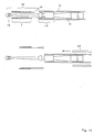
An den proximalen und/oder distalen Filamentenden können auch Verbindungselemente angebracht sein, die sich weiter in Richtung proximal/distal erstrecken und an deren Enden sich Verdickungen befinden. Das Verbindungselement kann bspw. ein Draht sein, der am Verknüpfungspunkt von zwei oder mehr Filamentenden angebracht ist und weiter in axialer Richtung verläuft. Besondere Bedeutung haben die Verdickungen am proximalen Ende, wo die Verdickungen dazu vorgesehen sind, von einem Halteelement formschlüssig gehalten zu werden. Über das Halteelement ist das Implantat an eine Einführhilfe, insbesondere einen Einführ- oder Führungsdraht gekoppelt. Bei Ablösung des Implantats wird der Formschluss zwischen Verdickungen und Halteelement aufgehoben und das Implantat wird freigesetzt. Möglich ist aber auch das zusätzliche Vorsehen eines Halteelements am distalen Ende des Implantats.At the proximal and / or distal ends of the filament also connecting elements may be attached, which extend further in the direction of proximal / distal and at the ends of which are thickenings. The connecting element may, for example, be a wire which is attached at the point of connection of two or more filament ends and extends further in the axial direction. Of particular importance are the thickenings at the proximal end, where the thickenings are intended to be held in a form-fitting manner by a holding element. The implant is coupled to an insertion aid, in particular an insertion or guide wire, via the retaining element. When replacing the implant, the positive connection between thickening and holding element is released and the implant is released. However, it is also possible to additionally provide a holding element at the distal end of the implant.
Eine Ausgestaltung der Verbindungselemente in anderer als Kugelform ist ebenfalls möglich, beispielsweise in Form von Ankern, Rechtecken oder anderen Formteilen. Die Verbindungselemente funktionieren nach dem Schlüssel/Schloss-Prinzip, d. h. sie wirken mit einem Halteelement zusammen, das peripher entsprechende Ausnehmungen oder Aufnahmen aufweist. Solange Halteelement mit angefügtem Implantat in gestreckter und im Durchmesser verkleinerter Form innerhalb eines Katheters geführt werden, werden beide durch die Katheterwand zwangsweise im Verbund gehalten; nach Austritt des Halteelements aus dem Katheter weitet sich das Implantat zu seinem Enddurchmesser auf und befreit sich dadurch aus den Aufnahmen des Halteelements. Festlegung und Ablösung der Verbindungselemente vom Halteelement ist aber auch auf andere Weise möglich. In der Regel ist das Halteelement rotationssymmetrisch und kann z. B. aus Edelstahl oder Nitinol hergestellt sein.An embodiment of the connecting elements in other than spherical shape is also possible, for example in the form of anchors, rectangles or other shaped parts. The connecting elements work according to the key / lock principle, ie they cooperate with a holding element having peripherally corresponding recesses or receptacles. Solange holding element with attached implant in an elongated and reduced in diameter form within a catheter guided, both are forcibly held together by the catheter wall; after the outlet of the retaining element from the catheter, the implant expands to its final diameter and thereby frees itself from the receptacles of the retaining element. Fixing and detachment of the connecting elements from the retaining element is also possible in other ways. In general, the holding element is rotationally symmetric and z. B. made of stainless steel or nitinol.
Die Fixierung des Implantats in den Ausnehmungen oder Aufnahmen des Halteelements kann auch durch eine separate schlauchartige Abdeckung erfolgen, die formschlüssig über das Halteelement mit eingepassten Verbindungselementen bzw. Verbindern gezogen ist. Die Abdeckung wird nach Erreichen der Endposition des Implantats zurückgezogen und setzt damit das Implantat frei. Anschließend können Halteelement mit Einführdraht, Abdeckung und Katheter zurückgezogen werden. Bei der Abdeckung kann es sich um einen Schlauch aus Kunststoff, eine Hülse aus Kunststoff oder Metall, eine Spiralwendel aus Metall oder auch aus Kombinationen hieraus handeln. Eine Fixierung der Abdeckung am Einführdraht gegen unbeabsichtigtes Verschieben ist mit einer Klemmvorrichtung möglich, beispielsweise mit Hilfe eines Torquers. Die Abdeckung muss nicht den gesamten Einführdraht abdecken, ausreichend ist eine Erstreckung der Abdeckung über das Halteelement und den distalen Teil des Einführdrahtes. Der Rückzug der Abdeckung erfolgt in diesem Fall über einen zweiten Draht oder Faden, der parallel zum Einführdraht von der Abdeckung aus in Richtung proximal verläuft.The fixation of the implant in the recesses or receptacles of the retaining element can also be effected by a separate tubular cover, which is positively drawn over the retaining element with fitted connecting elements or connectors. The cover is withdrawn after reaching the end position of the implant, thus exposing the implant. Subsequently, retaining element with insertion wire, cover and catheter can be withdrawn. The cover can be a hose made of plastic, a sleeve made of plastic or metal, a spiral spiral made of metal or combinations thereof. A fixation of the cover on the insertion against unintentional displacement is possible with a clamping device, for example by means of a Torquers. The cover does not have to cover the entire insertion wire, sufficient is an extension of the cover over the retaining element and the distal part of the insertion wire. The withdrawal of the cover takes place in this case via a second wire or thread which extends parallel to the insertion wire from the cover in the proximal direction.
Entsprechend betrifft die Erfindung auch die Kombination aus einem Implantat der vorbezeichneten Art und einem Einführdraht, an den das Implantat über das Halteelement gekoppelt ist.Accordingly, the invention also relates to the combination of an implant of the aforementioned type and an insertion wire to which the implant is coupled via the retaining element.
Wie schon vorstehend erwähnt, wird die Kombination aus Halteelement und Implantat durch einen endovaskulären Katheter geführt. Dazu kann das Halteelement an seiner Peripherie mit Ausnehmungen zur Aufnahme der Verbindungselemente des Implantats versehen sein. Dabei ist der Durchmesser des Halteelements so bemessen, dass er ohne Weiteres durch einen üblichen Katheter geführt werden kann, die Verbindungselemente aber von der Innenwand des Katheters in den Ausnehmungen gehalten werden. Insoweit ist eine kugelförmige Ausbildung der Verbindungselemente von Vorteil, da die Kontaktfläche mit der Innenwandung eines üblichen Katheters und damit die Reibung und der Führungswiderstand gering gehalten werden können.As already mentioned above, the combination of holding element and implant is guided through an endovascular catheter. For this purpose, the retaining element may be provided on its periphery with recesses for receiving the connecting elements of the implant. In this case, the diameter of the holding element is dimensioned so that it can be easily guided by a conventional catheter, but the connecting elements are held by the inner wall of the catheter in the recesses. In that regard, a spherical design of the connecting elements of advantage, since the contact surface with the inner wall of a conventional catheter, and thus the friction and the guide resistance can be kept low.
Gemäß einer bevorzugten Ausführungsform befinden sich am proximalen Ende des Implantats Verdickungen, die vom Halteelement formschlüssig gehalten werden, wobei ein Abschnitt des Halteelements elektrolytisch korrodierbar ausgebildet ist, so dass nach elektrolytischer Auflösung des Abschnitts das proximale Ende des Implantats freigegeben wird. In diesem Fall wird die Ablösung des Implantats nicht lediglich durch Ausschieben aus dem Katheter bzw. Zurückziehen einer Abdeckung herbeigeführt, stattdessen ist zumindest auch die elektrolytische Korrosion eines Abschnitts des Halteelements notwendig. Der korrodierbare Abschnitt ist dabei so angeordnet, dass er den Austritt der in das Halteelement hineinragenden Verdickungen verhindert. Es kann sich z. B. um einen Stift handeln, der zwischen den Verdickungen angeordnet ist und diese auseinanderhält, so dass der Durchmesser des Implantats am proximalen Ende für einen Austritt aus dem Halteelement zu groß ist. Die Festlegung des Implantats am Halteelement über Formschluss, der über die elektrolytische Ablösbarkeit eines Abschnitts des Halteelements kontrolliert wird, ist im Hinblick auf die sichere Steuerbarkeit der Platzierung und ggf. auch die Repositionierung oder das Zurückziehen des Implantats besonders vorteilhaft. Selbstverständlich ist aber auch eine reine elektrolytische Ablösbarkeit des Implantats vom Halteelement denkbar, wie sie im Stand der Technik für Stents und Coils bekannt ist.According to a preferred embodiment, thickenings are held on the proximal end of the implant, which are held in a form-fitting manner by the holding element, wherein a portion of the holding element is electrolytically corrodible, so that after electrolytic dissolution of the section, the proximal end of the implant is released. In this case, the detachment of the implant is not brought about merely by pushing out of the catheter or retraction of a cover, instead at least the electrolytic corrosion of a portion of the holding element is necessary. The corrodible section is arranged so that it prevents the escape of the protruding into the holding element thickenings. It can be z. Example, act around a pin which is arranged between the thickenings and this apart, so that the diameter of the implant at the proximal end for a discharge from the holding element is too large. The determination of the implant on the holding element via positive engagement, which is controlled by the electrolytic detachability of a portion of the holding element, is particularly advantageous with regard to the secure controllability of the placement and possibly also the repositioning or retraction of the implant. Of course, however, a pure electrolytic detachability of the implant from the holding element is conceivable, as is known in the prior art for stents and coils.
Eine weitere Möglichkeit besteht darin, als korrodierbar ausgebildeten Abschnitt des Halteelements eine Scheibe mit einer Öffnung zu verwenden, wobei sich die am proximalen Ende des Implantats befindlichen Verdickungen durch die Öffnung erstrecken und wobei der Durchmesser der Öffnung so auf die Verdickungen abgestimmt ist, dass ein Durchtreten der Verdickungen durch die Öffnung bei intakter Scheibe ausgeschlossen ist. Erst wenn sich die Scheibe durch Anlegen einer Spannung zumindest teilweise auflöst, können die Verdickungen des Implantats aus dem Halteelement austreten.Another possibility is to use as a corrodible formed portion of the holding member, a disc having an opening, wherein the proximal end of the implant located thickenings extend through the opening and wherein the diameter of the opening is adapted to the thickenings that a passage the thickening is excluded by the opening with intact disc. Only when the disc at least partially dissolves by applying a voltage, the thickening of the implant can escape from the holding element.
Für den elektrolytisch korrodierbaren Abschnitt können verschiedene Materialien verwendet werden, die eine rasche Ablösbarkeit gewährleisten und darüber hinaus medizinisch verträglich sind. Beispiele sind Edelstahl, Magnesium, Magnesiumlegierungen oder Cobalt-Chrom-Legierungen.For the electrolytically corrodible section, various materials can be used which ensure rapid peelability and are also medically acceptable. Examples are stainless steel, magnesium, magnesium alloys or cobalt-chromium alloys.
Die oben beschriebene Kombination aus formschlüssiger Festlegung des Implantats am Halteelement mit elektrolytischer Auflösung eines Abschnitts des Halteelements, die zur Freisetzung des Implantats führt, ist auch unabhängig von der hier beschriebenen Erfindung der Verbindung der sich kreuzenden Filamente an den proximalen Kreuzungspunkten möglich, d. h. bei einem Implantat gemäß dem Oberbegriff von Anspruch 1. Auch diese Variante ist Gegenstand der Anmeldung.The above-described combination of positive fixing of the implant on the holding member with electrolytic dissolution of a portion of the holding member, which leads to the release of the implant is also possible, independent of the invention described here, the connection of the crossing filaments at the proximal crossing points, d. H. in an implant according to the preamble of
Das Halteelement kann aus zwei zueinander beabstandeten Fixierelementen bestehen, die das Implantat zwischen sich gespannt aufnehmen. In diesem Fall weisen beide Fixierelemente die entsprechenden Aufnahmen für die Verbindungselemente des Implantats und das Implantat entsprechende Verbindungselemente sowohl an seinem proximalen wie auch an seinem distalen Ende auf.The holding element may consist of two mutually spaced fixing elements, the Pick up the implant between them. In this case, both fixing elements have the corresponding receptacles for the connection elements of the implant and the implant-corresponding connecting elements both at its proximal and at its distal end.
Ein entsprechend ausgebildetes Halteelement mit zwei Fixierelementen kann die beiden Fixierelemente in einem definierten Abstand an ein und demselben Einführdraht aufweisen, wodurch das Implantat bei vorgegebener Länge auch eine definierte Streckung und Spannung erfährt. Auf diese Art und Weise ist sichergestellt, dass keine Überdehnung stattfindet und die Rückstellkräfte nach der Freisetzung im Gefäß voll wirksam werden können. Alternativ ist aber auch eine Fixierung der Fixierelemente an zwei separaten Einführdrähten möglich, die eine Einstellung oder Streckung des Implantats durch den behandelnden Arzt oder über eine entsprechende Feststellvorrichtung ermöglicht. Der zweite Einführdraht kann auch als Führungsrohr ausgebildet sein.A correspondingly formed holding element with two fixing elements can have the two fixing elements at a defined distance on one and the same insertion wire, as a result of which the implant also experiences a defined extension and tension for a given length. In this way it is ensured that no overstretching takes place and the restoring forces can become fully effective after release in the vessel. Alternatively, however, a fixation of the fixing elements on two separate insertion wires is possible, which allows adjustment or extension of the implant by the attending physician or a corresponding locking device. The second insertion wire can also be designed as a guide tube.
Gemäß einer weiteren vorteilhaften Ausführungsform verfügt der Einführdraht über eine Führungsdrahtspitze, die sich vom distalen Ende des Einführdrahtes weiter in Richtung distal in den Innenraum des Implantats erstreckt, insbesondere bis zum distalen Ende des Implantats oder darüber hinaus. Auf diese Weise wird bewirkt, dass auch nach Freisetzung des Implantats zunächst noch ein Objekt durch das Innere des Implantats verläuft, solange der Einführdraht nicht zurückgezogen wird. Dies ermöglicht die erneute Sondierung des Gefäßes bzw. Implantates, beispielsweise indem ein Katheter über den Einführdraht und daran anschließend die Führungsdrahtspitze geführt wird. Der Katheter wird auf diese Weise durch das freigesetzte und expandierte Implantat bewegt. Die Führungsdrahtspitze wird erst durch das endgültige Zurückziehen des Einführdrahtes entfernt.According to a further advantageous embodiment, the insertion wire has a guide wire tip which extends further from distal end of the insertion wire in the direction of the interior of the implant, in particular to the distal end of the implant or beyond. In this way, even after the release of the implant, an object still first passes through the interior of the implant, as long as the insertion wire is not retracted. This makes it possible to re-probe the vessel or implant, for example by guiding a catheter over the insertion wire and subsequently the guidewire tip. The catheter is thus moved through the released and expanded implant. The guidewire tip is removed only by the final retraction of the introducer wire.
Die Führungsdrahtspitze kann ein rotationssymmetrisches Design haben. Der Querschnitt kann rund, oval, rechteckig oder auf grundsätzlich beliebige andere Art geformt sein. Sinnvoll ist es darüber hinaus, die Führungsdrahtspitze visualisierbar zu machen, z. B. indem die Führungsdrahtspitze selbst zumindest teilweise aus einem röntgensichtbaren Material gefertigt wird oder indem die Führungsdrahtspitze an ihrem distalen Ende einen röntgendichten Marker aufweist. Hergestellt werden kann die Führungsdrahtspitze aus Edelstahl, Nitinol oder anderen Metallen.The guidewire tip may have a rotationally symmetric design. The cross section may be round, oval, rectangular or basically any other type. It makes sense, moreover, to make the guidewire tip visualizable, z. B. by the guidewire tip itself is at least partially made of a radiopaque material or in that the guidewire tip has a radiopaque marker at its distal end. The guidewire tip can be made of stainless steel, Nitinol or other metals.
Die Führungsdrahtspitze und der eigentliche Einführdraht können einstückig gefertigt sein, d. h. es handelt es sich letztlich um einen durchgehenden Draht. Möglich ist es aber auch, Führungsdrahtspitze und Einführdraht getrennt zu fertigen und erst nachträglich miteinander zu verbinden. Zumeist wird die Führungsdrahtspitze einen kleineren Durchmesser aufweisen als der Führungsdraht, d. h. der Querschnitt verringert sich vom Einführdraht zur Führungsdrahtspitze hin. Weiter vorteilhaft ist es darüber hinaus, wenn die Führungsdrahtspitze leicht konisch gestaltet ist, d. h. ihr Durchmesser in Richtung distal abnimmt, so dass sich die Flexibilität in Richtung distal erhöht.The guidewire tip and the actual insertion wire may be made in one piece, d. H. it is ultimately a continuous wire. It is also possible, however, to manufacture guidewire tip and insertion wire separately and to subsequently connect them together. In most cases, the guidewire tip will have a smaller diameter than the guidewire, i. H. the cross-section decreases from the insertion wire to the guidewire tip. It is also advantageous if the guide wire tip is slightly conical, d. H. their diameter decreases distally so that the flexibility increases distally.
Die beschriebene Variante mit Führungsdrahtspitze ist auch unabhängig von der hier beschriebenen Erfindung der Verbindung der sich kreuzenden Filamente an den proximalen Kreuzungspunkten ausführbar, d. h. bei einem Implantat gemäß dem Oberbegriff von Anspruch 1. Auch diese Variante ist Gegenstand der Anmeldung.The described variant with guidewire tip is also independent of the invention described here, the connection of the intersecting filaments at the proximal crossing points executable, d. H. in an implant according to the preamble of
Der Erfindung wird durch die nachfolgenden Darstellungen näher erläutert. Es zeigt:The invention is explained in more detail by the following illustrations. It shows:
Der Winkel Theta bezeichnet den Geflechtswinkel zur Längsachse, der im entspannten Zustand beim Nenndurchmesser bis zu 80° betragen kann. Bei der Längung des Geflechts im Katheter kann der Winkel Theta bis auf ca. 7° abnehmen.The angle theta designates the braid angle to the longitudinal axis, which can be up to 80 ° in the relaxed state at the nominal diameter. When stretching the braid in the catheter, the angle theta can decrease to about 7 °.
Es versteht sich, dass der Nenndurchmesser des Geflechts auf das Lumen des Zielgefäßes an der zu behandelnden Stelle abgestimmt ist.It is understood that the nominal diameter of the braid is tuned to the lumen of the target vessel at the site to be treated.
Das Geflecht wird auf einer konventionellen Flechtmaschine hergestellt und liegt als Endlosgeflecht vor. Geflochten wird auf einem Dorn, dessen äußere Abmessungen dem Innendurchmesser der späteren Produkte entsprechen.The braid is made on a conventional braiding machine and is available as an endless braid. Braiding is done on a mandrel whose external dimensions correspond to the inside diameter of the later products.
Die Flechtmaschine und deren Besetzung bestimmt die Struktur des Geflechts, z. B. die Anzahl der Fäden, den Fadenverlauf und die Anzahl der Kreuzungspunkte am Umfang und per Schlaglänge. Die Anzahl der Fäden ist abhängig von der Zahl der Klöppel, wobei die Klöppel je zur Hälfte in beide Richtungen um den Flechtkern laufen.The braiding machine and its occupation determines the structure of the braid, z. As the number of threads, the thread shape and the number of crossing points on the perimeter and per stroke length. The number of threads depends on the number of bobbins, with the bobbins half running in both directions around the batt core.
Die Filamente bestehen in der Regel aus Metall, beispielsweise aus Stahldraht, röntgendichten Platinmetallen oder -legierungen oder Nitinol. Es können auch Kunststofffäden, die über die nötige Flexibilität verfügen, verwendet werden. Die Filamentstärke beträgt idealerweise 0,01 bis 0,2 mm, insbesondere 0,02 bis 0,1 mm. Um eine hohe Abdeckung der Wandfläche zu erzielen, kann anstelle von Drahtmaterial auch ein Flachbandmaterial verwandt werden, beispielsweise mit einer Breite von 0,05 bis 0,5 mm, vorzugsweise bis 0,1 mm, bei den oben angegebenen Stärken.The filaments are usually made of metal, such as steel wire, radiopaque platinum metals or alloys or Nitinol. Plastic threads that have the necessary flexibility can also be used. The filament thickness is ideally 0.01 to 0.2 mm, in particular 0.02 to 0.1 mm. In order to achieve a high coverage of the wall surface, instead of wire material and a flat strip material can be used, for example, with a width of 0.05 to 0.5 mm, preferably to 0.1 mm, with the above strengths.
Das erfindungsgemäße Geflecht kann aus Einzelfilamenten hergestellt werden (Fachung 1) oder auch aus zwei (Fachung 2) oder mehr Einzelfilamenten.The braid according to the invention can be produced from single filaments (compartment 1) or also from two (compartment 2) or more single filaments.
Eine Fachung von zwei oder eine noch höhere Fachung bringt eine höhere Oberflächendichte des Geflechts mit sich, bei gleichzeitiger Verringerung der Längenausdehnung während der Komprimierung des Geflechts. Diese höhere Oberflächendichte geht allerdings auf Kosten der Flexibilität, auch durch Erhöhung der Reibung und Spannung. Dem kann durch eine Erhöhung der Flechtigkeit entgegengewirkt werden, d. h. eine zwei oder höherflechtige Struktur bringt eine Erhöhung der Flexibilität mit sich. Erfindungsgemäß ist eine Flechtigkeit von 2 und eine Fachung von 2 bevorzugt.A two or more compartmentalization brings with it a higher surface density of the mesh, while reducing elongation during compression of the mesh. However, this higher surface density is at the expense of flexibility, also by increasing the friction and stress. This can be counteracted by increasing the weave, i. H. a two or more lofty structure brings with it an increase in flexibility. According to the invention, a weave of 2 and a shelf of 2 are preferred.
Nach der Auftrennung in für das Produkt spezifische Einheiten muss das Geflecht an den Enden geschlossen werden. Dies ist notwendig, um die Formstabilität des Flechtkörpers zu gewährleisten und um Gefäßverletzungen zu vermeiden. Hierfür ist auch die Ordnung der Struktur an den Enden des Geflechts notwendig.After separation into units specific to the product, the braid must be closed at the ends. This is necessary to ensure the dimensional stability of the braided body and to avoid vessel injuries. For this, the order of the structure at the ends of the mesh is necessary.
In
Wie in
In
In
Zusätzlich zeigt die
In
In
Die
In
Eine weitere Möglichkeit der elektrolytischen Ablösbarkeit ist in
In
Durch Zurückziehen der Abdeckung
ZITATE ENTHALTEN IN DER BESCHREIBUNG QUOTES INCLUDE IN THE DESCRIPTION
Diese Liste der vom Anmelder aufgeführten Dokumente wurde automatisiert erzeugt und ist ausschließlich zur besseren Information des Lesers aufgenommen. Die Liste ist nicht Bestandteil der deutschen Patent- bzw. Gebrauchsmusteranmeldung. Das DPMA übernimmt keinerlei Haftung für etwaige Fehler oder Auslassungen.This list of the documents listed by the applicant has been generated automatically and is included solely for the better information of the reader. The list is not part of the German patent or utility model application. The DPMA assumes no liability for any errors or omissions.
Zitierte PatentliteraturCited patent literature
- US 4655771 A [0009] US 4655771A [0009]
- US 5061275 A [0010] US 5061275 A [0010]
- WO 2008/107172 A1 [0013] WO 2008/107172 A1 [0013]
- DE 102009006180 A1 [0014, 0035] DE 102009006180 A1 [0014, 0035]
Claims (15)
Priority Applications (14)
| Application Number | Priority Date | Filing Date | Title |
|---|---|---|---|
| DE102010044746A DE102010044746A1 (en) | 2010-09-08 | 2010-09-08 | Implant for influencing the blood flow in arteriovenous malformations |
| ES15189454T ES2959263T3 (en) | 2010-09-08 | 2011-09-07 | Implant to influence blood circulation in arteriovenous malformations |
| JP2013527492A JP5889902B2 (en) | 2010-09-08 | 2011-09-07 | Implants affecting blood flow in areas of arteriovenous malformations |
| CN201180053870.XA CN103200884B (en) | 2010-09-08 | 2011-09-07 | For affecting the implant of the blood flow in arteriovenous malformotion |
| PCT/EP2011/004498 WO2012031748A2 (en) | 2010-09-08 | 2011-09-07 | Implant for influencing the blood flow in arteriovenous defects |
| KR1020137008912A KR101877586B1 (en) | 2010-09-08 | 2011-09-07 | Implant for influencing the blood flow in arteriovenous malformations |
| US13/821,350 US10265154B2 (en) | 2010-09-08 | 2011-09-07 | Implant for influencing the blood flow in arteriovenous defects |
| BR112013005678-9A BR112013005678B1 (en) | 2010-09-08 | 2011-09-07 | blood vessel implant and combination of an implant |
| EP11764675.2A EP2613743B1 (en) | 2010-09-08 | 2011-09-07 | Implant for influencing the blood flow in arteriovenous defects |
| CN201610131653.2A CN105902330B (en) | 2010-09-08 | 2011-09-07 | Implantation material for influencing the blood flow in arteriovenous malformation |
| ES11764675.2T ES2561531T3 (en) | 2010-09-08 | 2011-09-07 | Implant for the influence of blood flow in arteriovenous malformations |
| EP15189454.0A EP3000445B1 (en) | 2010-09-08 | 2011-09-07 | Implant for influencing the blood flow related to arteriovenous defects |
| JP2016028048A JP2016116906A (en) | 2010-09-08 | 2016-02-17 | Implant for influencing blood flow in area of arteriovenous malformations |
| JP2018089462A JP6682571B2 (en) | 2010-09-08 | 2018-05-07 | Implants that affect blood flow in the area of arteriovenous malformations |
Applications Claiming Priority (1)
| Application Number | Priority Date | Filing Date | Title |
|---|---|---|---|
| DE102010044746A DE102010044746A1 (en) | 2010-09-08 | 2010-09-08 | Implant for influencing the blood flow in arteriovenous malformations |
Publications (1)
| Publication Number | Publication Date |
|---|---|
| DE102010044746A1 true DE102010044746A1 (en) | 2012-03-08 |
Family
ID=44759640
Family Applications (1)
| Application Number | Title | Priority Date | Filing Date |
|---|---|---|---|
| DE102010044746A Pending DE102010044746A1 (en) | 2010-09-08 | 2010-09-08 | Implant for influencing the blood flow in arteriovenous malformations |
Country Status (9)
| Country | Link |
|---|---|
| US (1) | US10265154B2 (en) |
| EP (2) | EP2613743B1 (en) |
| JP (3) | JP5889902B2 (en) |
| KR (1) | KR101877586B1 (en) |
| CN (2) | CN103200884B (en) |
| BR (1) | BR112013005678B1 (en) |
| DE (1) | DE102010044746A1 (en) |
| ES (2) | ES2561531T3 (en) |
| WO (1) | WO2012031748A2 (en) |
Cited By (3)
| Publication number | Priority date | Publication date | Assignee | Title |
|---|---|---|---|---|
| WO2014062448A1 (en) * | 2012-10-19 | 2014-04-24 | Boston Scientific Scimed, Inc. | Anti-thrombus feature for implanted medical devices |
| WO2014064181A1 (en) * | 2012-10-24 | 2014-05-01 | Joline Gmbh & Co. Kg | Braided stent and method for producing same |
| US10463377B2 (en) | 2014-01-16 | 2019-11-05 | Boston Scientific Scimed, Inc. | Retrieval wire centering device |
Families Citing this family (54)
| Publication number | Priority date | Publication date | Assignee | Title |
|---|---|---|---|---|
| US10716573B2 (en) | 2008-05-01 | 2020-07-21 | Aneuclose | Janjua aneurysm net with a resilient neck-bridging portion for occluding a cerebral aneurysm |
| US10028747B2 (en) | 2008-05-01 | 2018-07-24 | Aneuclose Llc | Coils with a series of proximally-and-distally-connected loops for occluding a cerebral aneurysm |
| DE202008009604U1 (en) | 2008-07-17 | 2008-11-27 | Sahl, Harald, Dr. | Membrane implant for the treatment of cerebral artery aneurysms |
| US9358140B1 (en) | 2009-11-18 | 2016-06-07 | Aneuclose Llc | Stent with outer member to embolize an aneurysm |
| DE102010051740A1 (en) | 2010-11-19 | 2012-05-24 | Phenox Gmbh | thrombectomy |
| DE102011011869A1 (en) | 2011-02-22 | 2012-08-23 | Phenox Gmbh | implant |
| DE102011012501A1 (en) | 2011-02-25 | 2012-08-30 | Phenox Gmbh | Implant with fiber fleece |
| DE102011101522A1 (en) | 2011-05-13 | 2012-11-15 | Phenox Gmbh | thrombectomy |
| US9326774B2 (en) | 2012-08-03 | 2016-05-03 | Covidien Lp | Device for implantation of medical devices |
| US10561509B2 (en) | 2013-03-13 | 2020-02-18 | DePuy Synthes Products, Inc. | Braided stent with expansion ring and method of delivery |
| WO2014171183A1 (en) * | 2013-04-16 | 2014-10-23 | 株式会社カネカ | Medical tubular body |
| JP6689605B2 (en) * | 2013-04-16 | 2020-04-28 | 株式会社カネカ | Medical tubular body |
| BR112015032164A2 (en) | 2013-06-25 | 2020-03-31 | Nike Innovate Cv | footwear with braided upper |
| US10863794B2 (en) | 2013-06-25 | 2020-12-15 | Nike, Inc. | Article of footwear having multiple braided structures |
| DE102013014523A1 (en) * | 2013-09-03 | 2015-03-05 | Phenox Gmbh | Insertion and detachment system for implants |
| US9814466B2 (en) | 2014-08-08 | 2017-11-14 | Covidien Lp | Electrolytic and mechanical detachment for implant delivery systems |
| US9808256B2 (en) | 2014-08-08 | 2017-11-07 | Covidien Lp | Electrolytic detachment elements for implant delivery systems |
| US10206796B2 (en) * | 2014-08-27 | 2019-02-19 | DePuy Synthes Products, Inc. | Multi-strand implant with enhanced radiopacity |
| JP6425981B2 (en) * | 2014-11-26 | 2018-11-21 | 株式会社Pentas | Self-expanding stent |
| US10674791B2 (en) | 2014-12-10 | 2020-06-09 | Nike, Inc. | Braided article with internal midsole structure |
| US9668544B2 (en) | 2014-12-10 | 2017-06-06 | Nike, Inc. | Last system for articles with braided components |
| DE102015103240A1 (en) * | 2015-03-05 | 2016-09-08 | Phenox Gmbh | implant delivery |
| US9717503B2 (en) | 2015-05-11 | 2017-08-01 | Covidien Lp | Electrolytic detachment for implant delivery systems |
| US20160345675A1 (en) | 2015-05-26 | 2016-12-01 | Nike, Inc. | Hybrid Braided Article |
| US10555581B2 (en) * | 2015-05-26 | 2020-02-11 | Nike, Inc. | Braided upper with multiple materials |
| US11103028B2 (en) | 2015-08-07 | 2021-08-31 | Nike, Inc. | Multi-layered braided article and method of making |
| EP3346947A4 (en) * | 2015-09-10 | 2019-07-24 | Ikonano Venture Partners, LLC | Polymeric electrospun embolization device and methods of use |
| EP3349670B1 (en) | 2015-09-18 | 2020-09-09 | Microvention, Inc. | Releasable delivery system |
| US10335299B2 (en) * | 2015-09-18 | 2019-07-02 | Terumo Corporation | Vessel prosthesis |
| US10004617B2 (en) | 2015-10-20 | 2018-06-26 | Cook Medical Technologies Llc | Woven stent device and manufacturing method |
| US10953097B2 (en) | 2015-11-02 | 2021-03-23 | Nanofiber Solutions. Llc | Electrospun fibers having contrast agents and methods of making the same |
| JP6607586B2 (en) | 2016-02-16 | 2019-11-20 | 株式会社Pentas | Stent |
| US10828037B2 (en) | 2016-06-27 | 2020-11-10 | Covidien Lp | Electrolytic detachment with fluid electrical connection |
| US10828039B2 (en) | 2016-06-27 | 2020-11-10 | Covidien Lp | Electrolytic detachment for implantable devices |
| US11051822B2 (en) | 2016-06-28 | 2021-07-06 | Covidien Lp | Implant detachment with thermal activation |
| CN106063735A (en) * | 2016-07-14 | 2016-11-02 | 杨牟 | A kind of artificial blood vessel bracket and carrier thereof |
| US10292851B2 (en) | 2016-09-30 | 2019-05-21 | DePuy Synthes Products, Inc. | Self-expanding device delivery apparatus with dual function bump |
| WO2018204106A1 (en) * | 2017-05-03 | 2018-11-08 | St. Jude Medical, Cardiology Division, Inc. | Collapsible medical device having an open lumen |
| US11051573B2 (en) | 2017-05-31 | 2021-07-06 | Nike, Inc. | Braided articles and methods for their manufacture |
| US10806210B2 (en) | 2017-05-31 | 2020-10-20 | Nike, Inc. | Braided articles and methods for their manufacture |
| US11202483B2 (en) | 2017-05-31 | 2021-12-21 | Nike, Inc. | Braided articles and methods for their manufacture |
| CN107028682B (en) * | 2017-06-08 | 2019-05-24 | 有研医疗器械(北京)有限公司 | A kind of film-coated vascular bracket of the submissive type of high intensity |
| CN107714243B (en) * | 2017-09-29 | 2021-05-07 | 依奈德医疗技术(上海)有限公司 | Self-expansion type nasal stent |
| AU2019204522A1 (en) | 2018-07-30 | 2020-02-13 | DePuy Synthes Products, Inc. | Systems and methods of manufacturing and using an expansion ring |
| US10456280B1 (en) | 2018-08-06 | 2019-10-29 | DePuy Synthes Products, Inc. | Systems and methods of using a braided implant |
| EP3763339B1 (en) * | 2018-09-26 | 2023-05-10 | Japan Lifeline Co., Ltd. | Stent and stent graft |
| US11039944B2 (en) | 2018-12-27 | 2021-06-22 | DePuy Synthes Products, Inc. | Braided stent system with one or more expansion rings |
| CN110037839B (en) * | 2019-05-28 | 2024-03-12 | 南微医学科技股份有限公司 | Endoluminal stent and preparation method thereof |
| EP3998962A1 (en) | 2019-07-17 | 2022-05-25 | Boston Scientific Scimed, Inc. | Left atrial appendage implant with continuous covering |
| CN114340516A (en) | 2019-08-30 | 2022-04-12 | 波士顿科学医学有限公司 | Left atrial appendage implant with sealing disk |
| EP3827762B1 (en) * | 2019-11-28 | 2023-06-07 | Acandis GmbH | Medical device for intravascular treatment and method of manufacturing the same |
| US11932976B2 (en) * | 2020-03-11 | 2024-03-19 | KA Medical, LLC | Braided medical device and method |
| WO2021195085A1 (en) | 2020-03-24 | 2021-09-30 | Boston Scientific Scimed, Inc. | Medical system for treating a left atrial appendage |
| DE102022114379A1 (en) | 2022-06-08 | 2023-12-14 | Acandis Gmbh | Medical device and manufacturing process |
Citations (4)
| Publication number | Priority date | Publication date | Assignee | Title |
|---|---|---|---|---|
| US4655771A (en) | 1982-04-30 | 1987-04-07 | Shepherd Patents S.A. | Prosthesis comprising an expansible or contractile tubular body |
| US5061275A (en) | 1986-04-21 | 1991-10-29 | Medinvent S.A. | Self-expanding prosthesis |
| WO2008107172A1 (en) | 2007-03-06 | 2008-09-12 | Phenox Gmbh | Implant for influencing blood flow |
| DE102009006180A1 (en) | 2008-10-29 | 2010-05-06 | Acandis Gmbh & Co. Kg | Medical implant and method for manufacturing an implant |
Family Cites Families (37)
| Publication number | Priority date | Publication date | Assignee | Title |
|---|---|---|---|---|
| US4441215A (en) * | 1980-11-17 | 1984-04-10 | Kaster Robert L | Vascular graft |
| US4733665C2 (en) * | 1985-11-07 | 2002-01-29 | Expandable Grafts Partnership | Expandable intraluminal graft and method and apparatus for implanting an expandable intraluminal graft |
| US5064435A (en) * | 1990-06-28 | 1991-11-12 | Schneider (Usa) Inc. | Self-expanding prosthesis having stable axial length |
| US5405377A (en) * | 1992-02-21 | 1995-04-11 | Endotech Ltd. | Intraluminal stent |
| US6336938B1 (en) * | 1992-08-06 | 2002-01-08 | William Cook Europe A/S | Implantable self expanding prosthetic device |
| DE9318988U1 (en) * | 1993-12-10 | 1994-02-03 | Mann & Hummel Filter | Fastener |
| US5476508A (en) * | 1994-05-26 | 1995-12-19 | Tfx Medical | Stent with mutually interlocking filaments |
| DE4424242A1 (en) * | 1994-07-09 | 1996-01-11 | Ernst Peter Prof Dr M Strecker | Endoprosthesis implantable percutaneously in a patient's body |
| US5630829A (en) | 1994-12-09 | 1997-05-20 | Intervascular, Inc. | High hoop strength intraluminal stent |
| GB9522332D0 (en) * | 1995-11-01 | 1996-01-03 | Biocompatibles Ltd | Braided stent |
| JP3815622B2 (en) | 1996-03-07 | 2006-08-30 | エム イー ディー インスティチュート,インク | Inflatable stent |
| DE19703482A1 (en) * | 1997-01-31 | 1998-08-06 | Ernst Peter Prof Dr M Strecker | Stent |
| US6174330B1 (en) * | 1997-08-01 | 2001-01-16 | Schneider (Usa) Inc | Bioabsorbable marker having radiopaque constituents |
| US6264689B1 (en) * | 1998-03-31 | 2001-07-24 | Scimed Life Systems, Incorporated | Low profile medical stent |
| US7018401B1 (en) * | 1999-02-01 | 2006-03-28 | Board Of Regents, The University Of Texas System | Woven intravascular devices and methods for making the same and apparatus for delivery of the same |
| US6364895B1 (en) * | 1999-10-07 | 2002-04-02 | Prodesco, Inc. | Intraluminal filter |
| US6585758B1 (en) * | 1999-11-16 | 2003-07-01 | Scimed Life Systems, Inc. | Multi-section filamentary endoluminal stent |
| JP2002272855A (en) * | 2001-03-14 | 2002-09-24 | Piolax Medical Device:Kk | Stent |
| US6716238B2 (en) * | 2001-05-10 | 2004-04-06 | Scimed Life Systems, Inc. | Stent with detachable tethers and method of using same |
| DE10127602A1 (en) | 2001-05-31 | 2002-12-05 | Impag Gmbh Medizintechnik | Stent consists of hollow cylindrical main part of intersecting filaments forming mesh with cells, and at least pairs of free ends |
| US7001422B2 (en) * | 2002-09-23 | 2006-02-21 | Cordis Neurovascular, Inc | Expandable stent and delivery system |
| US7473271B2 (en) * | 2003-04-11 | 2009-01-06 | Boston Scientific Scimed, Inc. | Stent delivery system with securement and deployment accuracy |
| FR2858208B1 (en) | 2003-07-28 | 2006-04-14 | Perouse Laboratoires | ENDOPROSTHESIS COMPRISING A TUBULAR TRELLIS. |
| FR2865926B1 (en) * | 2004-02-11 | 2006-05-12 | Perouse Laboratoires | TUBULAR PROSTHESIS. |
| US7993387B2 (en) * | 2004-05-14 | 2011-08-09 | Boston Scientific Scimed, Inc. | Stent with reduced weld profiles and a closed-end wire configuration |
| AU2005247490B2 (en) * | 2004-05-25 | 2011-05-19 | Covidien Lp | Flexible vascular occluding device |
| CN2741534Y (en) * | 2004-10-12 | 2005-11-23 | 微创医疗器械(上海)有限公司 | Anti internal leakage film coated rack |
| DE102005019782A1 (en) * | 2005-04-28 | 2006-11-09 | Dendron Gmbh | Device for implantation of occlusion coils with internal securing means |
| EP2666508B1 (en) * | 2005-05-13 | 2019-07-24 | Boston Scientific Limited | Integrated stent repositioning and retrieval loop |
| US7486937B2 (en) * | 2005-05-17 | 2009-02-03 | Cirrus Logic, Inc. | Efficient RF amplifier topologies |
| US20060271097A1 (en) * | 2005-05-31 | 2006-11-30 | Kamal Ramzipoor | Electrolytically detachable implantable devices |
| US20070100414A1 (en) * | 2005-11-02 | 2007-05-03 | Cardiomind, Inc. | Indirect-release electrolytic implant delivery systems |
| US20080221666A1 (en) * | 2006-12-15 | 2008-09-11 | Cardiomind, Inc. | Stent systems |
| AU2008276344A1 (en) * | 2007-07-13 | 2009-01-22 | Stryker Corporation | Hybrid and portable power supplies for electrolytically detaching implantable medical devices |
| JP5366974B2 (en) * | 2007-12-21 | 2013-12-11 | マイクロベンション インコーポレイテッド | System and method for determining the position of a separation zone of a separable implant |
| AU2009217354B2 (en) * | 2008-02-22 | 2013-10-10 | Covidien Lp | Methods and apparatus for flow restoration |
| CN101606869A (en) * | 2009-07-13 | 2009-12-23 | 成正辉 | Cerebral aneurysm endovascular plastic repair bracket and conveyer device thereof |
-
2010
- 2010-09-08 DE DE102010044746A patent/DE102010044746A1/en active Pending
-
2011
- 2011-09-07 EP EP11764675.2A patent/EP2613743B1/en active Active
- 2011-09-07 EP EP15189454.0A patent/EP3000445B1/en active Active
- 2011-09-07 JP JP2013527492A patent/JP5889902B2/en active Active
- 2011-09-07 ES ES11764675.2T patent/ES2561531T3/en active Active
- 2011-09-07 US US13/821,350 patent/US10265154B2/en active Active
- 2011-09-07 CN CN201180053870.XA patent/CN103200884B/en active Active
- 2011-09-07 BR BR112013005678-9A patent/BR112013005678B1/en active IP Right Grant
- 2011-09-07 WO PCT/EP2011/004498 patent/WO2012031748A2/en active Application Filing
- 2011-09-07 ES ES15189454T patent/ES2959263T3/en active Active
- 2011-09-07 KR KR1020137008912A patent/KR101877586B1/en active IP Right Grant
- 2011-09-07 CN CN201610131653.2A patent/CN105902330B/en active Active
-
2016
- 2016-02-17 JP JP2016028048A patent/JP2016116906A/en active Pending
-
2018
- 2018-05-07 JP JP2018089462A patent/JP6682571B2/en active Active
Patent Citations (5)
| Publication number | Priority date | Publication date | Assignee | Title |
|---|---|---|---|---|
| US4655771A (en) | 1982-04-30 | 1987-04-07 | Shepherd Patents S.A. | Prosthesis comprising an expansible or contractile tubular body |
| US4655771B1 (en) | 1982-04-30 | 1996-09-10 | Medinvent Ams Sa | Prosthesis comprising an expansible or contractile tubular body |
| US5061275A (en) | 1986-04-21 | 1991-10-29 | Medinvent S.A. | Self-expanding prosthesis |
| WO2008107172A1 (en) | 2007-03-06 | 2008-09-12 | Phenox Gmbh | Implant for influencing blood flow |
| DE102009006180A1 (en) | 2008-10-29 | 2010-05-06 | Acandis Gmbh & Co. Kg | Medical implant and method for manufacturing an implant |
Cited By (5)
| Publication number | Priority date | Publication date | Assignee | Title |
|---|---|---|---|---|
| WO2014062448A1 (en) * | 2012-10-19 | 2014-04-24 | Boston Scientific Scimed, Inc. | Anti-thrombus feature for implanted medical devices |
| WO2014064181A1 (en) * | 2012-10-24 | 2014-05-01 | Joline Gmbh & Co. Kg | Braided stent and method for producing same |
| DE102012020849B4 (en) | 2012-10-24 | 2023-10-19 | Joline Gmbh & Co. Kg | Process and endless braid for producing stents |
| US10463377B2 (en) | 2014-01-16 | 2019-11-05 | Boston Scientific Scimed, Inc. | Retrieval wire centering device |
| US11413047B2 (en) | 2014-01-16 | 2022-08-16 | Cardiac Pacemakers, Inc. | Occlusive medical implant |
Also Published As
| Publication number | Publication date |
|---|---|
| EP2613743B1 (en) | 2015-11-04 |
| JP2018134477A (en) | 2018-08-30 |
| EP2613743A2 (en) | 2013-07-17 |
| JP5889902B2 (en) | 2016-03-22 |
| ES2561531T3 (en) | 2016-02-26 |
| KR20140019286A (en) | 2014-02-14 |
| US20130211492A1 (en) | 2013-08-15 |
| JP2016116906A (en) | 2016-06-30 |
| JP2013541358A (en) | 2013-11-14 |
| ES2959263T3 (en) | 2024-02-22 |
| BR112013005678A2 (en) | 2016-05-03 |
| EP3000445A2 (en) | 2016-03-30 |
| WO2012031748A3 (en) | 2012-06-07 |
| CN103200884B (en) | 2016-03-30 |
| CN105902330B (en) | 2018-08-14 |
| US10265154B2 (en) | 2019-04-23 |
| JP6682571B2 (en) | 2020-04-15 |
| BR112013005678B1 (en) | 2021-01-05 |
| CN105902330A (en) | 2016-08-31 |
| EP3000445A3 (en) | 2016-08-17 |
| EP3000445B1 (en) | 2023-08-02 |
| KR101877586B1 (en) | 2018-08-09 |
| CN103200884A (en) | 2013-07-10 |
| WO2012031748A2 (en) | 2012-03-15 |
Similar Documents
| Publication | Publication Date | Title |
|---|---|---|
| EP2613743B1 (en) | Implant for influencing the blood flow in arteriovenous defects | |
| EP2799035B1 (en) | Implant for influencing blood flow | |
| DE60117983T2 (en) | BRAIDED, BRANCHED STENT AND MANUFACTURING METHOD | |
| EP1793743B1 (en) | Micro-spiral implantation device | |
| DE69632844T2 (en) | Self-expanding stent for introducing a medical device into a body cavity and manufacturing process | |
| DE60313736T2 (en) | PROSTHESIS IMPLANTABLE IN CARTRIDGE | |
| EP1542617A1 (en) | Medical implant | |
| EP3265038A1 (en) | Implant insertion system | |
| DE202008018523U1 (en) | Braided vascular devices without end clamps | |
| DE102014115337A1 (en) | Stent for splinting a vein and system for placing a stent | |
| EP3041439B1 (en) | Insertion and release system for implants | |
| EP3389511B1 (en) | Implant | |
| DE102016111568A1 (en) | Implant with detachment mechanism | |
| DE10301850B4 (en) | stent | |
| DE10301600A1 (en) | Combination stent, for implantation into blood vessels, has an outer stent with a grid/mesh structure and an inner stent to increase the mantle density for insertion into very small intracranial blood vessels | |
| DE102007025466B4 (en) | Fiber implant and combination with a fiber implant | |
| DE102020115605A1 (en) | Implant for the treatment of aneurysms | |
| WO2019174991A1 (en) | Temporary sealing of aneurysm necks | |
| WO2021250282A2 (en) | Insertion system for implants for treatment of bifurcation aneurysms | |
| DE102021132725A1 (en) | Implant for the treatment of aneurysms in the area of bifurcations |
Legal Events
| Date | Code | Title | Description |
|---|---|---|---|
| R012 | Request for examination validly filed |