DE102010056223A1 - Exhaust system for a vehicle engine with spark ignition - Google Patents
Exhaust system for a vehicle engine with spark ignition Download PDFInfo
- Publication number
- DE102010056223A1 DE102010056223A1 DE102010056223A DE102010056223A DE102010056223A1 DE 102010056223 A1 DE102010056223 A1 DE 102010056223A1 DE 102010056223 A DE102010056223 A DE 102010056223A DE 102010056223 A DE102010056223 A DE 102010056223A DE 102010056223 A1 DE102010056223 A1 DE 102010056223A1
- Authority
- DE
- Germany
- Prior art keywords
- washcoat
- filter
- exhaust system
- pore size
- substrate
- Prior art date
- Legal status (The legal status is an assumption and is not a legal conclusion. Google has not performed a legal analysis and makes no representation as to the accuracy of the status listed.)
- Ceased
Links
- 239000011148 porous material Substances 0.000 claims abstract description 143
- 239000000758 substrate Substances 0.000 claims abstract description 142
- 239000003054 catalyst Substances 0.000 claims abstract description 90
- 239000002245 particle Substances 0.000 claims abstract description 85
- 239000013618 particulate matter Substances 0.000 claims abstract description 80
- 238000002485 combustion reaction Methods 0.000 claims abstract description 44
- 238000011144 upstream manufacturing Methods 0.000 claims abstract description 36
- 238000001914 filtration Methods 0.000 claims abstract description 23
- 239000007787 solid Substances 0.000 claims abstract description 18
- 238000011068 loading method Methods 0.000 claims description 63
- 238000000034 method Methods 0.000 claims description 24
- 229910052751 metal Inorganic materials 0.000 claims description 17
- 239000002184 metal Substances 0.000 claims description 17
- 239000000919 ceramic Substances 0.000 claims description 10
- 238000011118 depth filtration Methods 0.000 claims description 7
- 239000006260 foam Substances 0.000 claims description 3
- 229930195733 hydrocarbon Natural products 0.000 description 58
- 150000002430 hydrocarbons Chemical class 0.000 description 53
- 239000007789 gas Substances 0.000 description 51
- UGFAIRIUMAVXCW-UHFFFAOYSA-N Carbon monoxide Chemical compound [O+]#[C-] UGFAIRIUMAVXCW-UHFFFAOYSA-N 0.000 description 34
- 238000006243 chemical reaction Methods 0.000 description 34
- 229910002091 carbon monoxide Inorganic materials 0.000 description 33
- 230000009467 reduction Effects 0.000 description 33
- 238000006722 reduction reaction Methods 0.000 description 33
- 239000003502 gasoline Substances 0.000 description 30
- 239000000203 mixture Substances 0.000 description 29
- MWUXSHHQAYIFBG-UHFFFAOYSA-N nitrogen oxide Inorganic materials O=[N] MWUXSHHQAYIFBG-UHFFFAOYSA-N 0.000 description 27
- KDLHZDBZIXYQEI-UHFFFAOYSA-N Palladium Chemical compound [Pd] KDLHZDBZIXYQEI-UHFFFAOYSA-N 0.000 description 26
- 239000010410 layer Substances 0.000 description 24
- 239000000446 fuel Substances 0.000 description 23
- BASFCYQUMIYNBI-UHFFFAOYSA-N platinum Chemical compound [Pt] BASFCYQUMIYNBI-UHFFFAOYSA-N 0.000 description 23
- 239000004215 Carbon black (E152) Substances 0.000 description 22
- 238000000576 coating method Methods 0.000 description 22
- 239000011248 coating agent Substances 0.000 description 20
- 229910052760 oxygen Inorganic materials 0.000 description 20
- 239000003570 air Substances 0.000 description 19
- QVGXLLKOCUKJST-UHFFFAOYSA-N atomic oxygen Chemical compound [O] QVGXLLKOCUKJST-UHFFFAOYSA-N 0.000 description 19
- 239000001301 oxygen Substances 0.000 description 19
- 230000000694 effects Effects 0.000 description 18
- 239000010948 rhodium Substances 0.000 description 18
- 230000003197 catalytic effect Effects 0.000 description 17
- 239000002808 molecular sieve Substances 0.000 description 17
- URGAHOPLAPQHLN-UHFFFAOYSA-N sodium aluminosilicate Chemical compound [Na+].[Al+3].[O-][Si]([O-])=O.[O-][Si]([O-])=O URGAHOPLAPQHLN-UHFFFAOYSA-N 0.000 description 17
- 210000004027 cell Anatomy 0.000 description 15
- 229910000510 noble metal Inorganic materials 0.000 description 13
- -1 platinum group metals Chemical class 0.000 description 13
- 238000009826 distribution Methods 0.000 description 12
- 238000002347 injection Methods 0.000 description 12
- 239000007924 injection Substances 0.000 description 12
- 230000003647 oxidation Effects 0.000 description 12
- 238000007254 oxidation reaction Methods 0.000 description 12
- 229910052697 platinum Inorganic materials 0.000 description 11
- CURLTUGMZLYLDI-UHFFFAOYSA-N Carbon dioxide Chemical compound O=C=O CURLTUGMZLYLDI-UHFFFAOYSA-N 0.000 description 10
- 239000000463 material Substances 0.000 description 10
- 229910052763 palladium Inorganic materials 0.000 description 10
- 239000003638 chemical reducing agent Substances 0.000 description 9
- 229910052878 cordierite Inorganic materials 0.000 description 9
- JSKIRARMQDRGJZ-UHFFFAOYSA-N dimagnesium dioxido-bis[(1-oxido-3-oxo-2,4,6,8,9-pentaoxa-1,3-disila-5,7-dialuminabicyclo[3.3.1]nonan-7-yl)oxy]silane Chemical compound [Mg++].[Mg++].[O-][Si]([O-])(O[Al]1O[Al]2O[Si](=O)O[Si]([O-])(O1)O2)O[Al]1O[Al]2O[Si](=O)O[Si]([O-])(O1)O2 JSKIRARMQDRGJZ-UHFFFAOYSA-N 0.000 description 9
- 239000003344 environmental pollutant Substances 0.000 description 9
- VNWKTOKETHGBQD-UHFFFAOYSA-N methane Chemical compound C VNWKTOKETHGBQD-UHFFFAOYSA-N 0.000 description 9
- 231100000719 pollutant Toxicity 0.000 description 9
- QGZKDVFQNNGYKY-UHFFFAOYSA-N Ammonia Chemical compound N QGZKDVFQNNGYKY-UHFFFAOYSA-N 0.000 description 8
- 230000008901 benefit Effects 0.000 description 8
- 229910052703 rhodium Inorganic materials 0.000 description 8
- 238000003860 storage Methods 0.000 description 8
- 238000012360 testing method Methods 0.000 description 8
- 238000009825 accumulation Methods 0.000 description 7
- 210000002421 cell wall Anatomy 0.000 description 7
- 238000006073 displacement reaction Methods 0.000 description 7
- MHOVAHRLVXNVSD-UHFFFAOYSA-N rhodium atom Chemical compound [Rh] MHOVAHRLVXNVSD-UHFFFAOYSA-N 0.000 description 7
- IJGRMHOSHXDMSA-UHFFFAOYSA-N Atomic nitrogen Chemical compound N#N IJGRMHOSHXDMSA-UHFFFAOYSA-N 0.000 description 6
- OKKJLVBELUTLKV-UHFFFAOYSA-N Methanol Chemical compound OC OKKJLVBELUTLKV-UHFFFAOYSA-N 0.000 description 6
- QAOWNCQODCNURD-UHFFFAOYSA-N Sulfuric acid Chemical compound OS(O)(=O)=O QAOWNCQODCNURD-UHFFFAOYSA-N 0.000 description 6
- 239000002105 nanoparticle Substances 0.000 description 6
- 230000008569 process Effects 0.000 description 6
- 239000002344 surface layer Substances 0.000 description 6
- 229910018072 Al 2 O 3 Inorganic materials 0.000 description 5
- 229910052788 barium Inorganic materials 0.000 description 5
- DSAJWYNOEDNPEQ-UHFFFAOYSA-N barium atom Chemical compound [Ba] DSAJWYNOEDNPEQ-UHFFFAOYSA-N 0.000 description 5
- 230000015572 biosynthetic process Effects 0.000 description 5
- 229910002092 carbon dioxide Inorganic materials 0.000 description 5
- 239000001569 carbon dioxide Substances 0.000 description 5
- 238000013461 design Methods 0.000 description 5
- 238000011161 development Methods 0.000 description 5
- 230000018109 developmental process Effects 0.000 description 5
- 238000009472 formulation Methods 0.000 description 5
- XLYOFNOQVPJJNP-UHFFFAOYSA-N water Substances O XLYOFNOQVPJJNP-UHFFFAOYSA-N 0.000 description 5
- 229910052684 Cerium Inorganic materials 0.000 description 4
- LFQSCWFLJHTTHZ-UHFFFAOYSA-N Ethanol Chemical compound CCO LFQSCWFLJHTTHZ-UHFFFAOYSA-N 0.000 description 4
- 229910052783 alkali metal Inorganic materials 0.000 description 4
- 150000001340 alkali metals Chemical class 0.000 description 4
- 229910021529 ammonia Inorganic materials 0.000 description 4
- 239000002585 base Substances 0.000 description 4
- 238000010531 catalytic reduction reaction Methods 0.000 description 4
- 229910052802 copper Inorganic materials 0.000 description 4
- 238000010790 dilution Methods 0.000 description 4
- 239000012895 dilution Substances 0.000 description 4
- 239000010419 fine particle Substances 0.000 description 4
- 229910052742 iron Inorganic materials 0.000 description 4
- 230000007246 mechanism Effects 0.000 description 4
- 229910052757 nitrogen Inorganic materials 0.000 description 4
- 239000002243 precursor Substances 0.000 description 4
- 239000004071 soot Substances 0.000 description 4
- 241000894007 species Species 0.000 description 4
- 239000011882 ultra-fine particle Substances 0.000 description 4
- OKTJSMMVPCPJKN-UHFFFAOYSA-N Carbon Chemical compound [C] OKTJSMMVPCPJKN-UHFFFAOYSA-N 0.000 description 3
- 239000006096 absorbing agent Substances 0.000 description 3
- 229910052784 alkaline earth metal Inorganic materials 0.000 description 3
- 150000001342 alkaline earth metals Chemical class 0.000 description 3
- 230000004323 axial length Effects 0.000 description 3
- 238000001354 calcination Methods 0.000 description 3
- 229910052799 carbon Inorganic materials 0.000 description 3
- GWXLDORMOJMVQZ-UHFFFAOYSA-N cerium Chemical compound [Ce] GWXLDORMOJMVQZ-UHFFFAOYSA-N 0.000 description 3
- 230000008021 deposition Effects 0.000 description 3
- 238000010586 diagram Methods 0.000 description 3
- 239000011159 matrix material Substances 0.000 description 3
- QSHDDOUJBYECFT-UHFFFAOYSA-N mercury Chemical compound [Hg] QSHDDOUJBYECFT-UHFFFAOYSA-N 0.000 description 3
- 229910052753 mercury Inorganic materials 0.000 description 3
- 150000002739 metals Chemical class 0.000 description 3
- VUZPPFZMUPKLLV-UHFFFAOYSA-N methane;hydrate Chemical compound C.O VUZPPFZMUPKLLV-UHFFFAOYSA-N 0.000 description 3
- 229910052759 nickel Inorganic materials 0.000 description 3
- QJGQUHMNIGDVPM-UHFFFAOYSA-N nitrogen group Chemical group [N] QJGQUHMNIGDVPM-UHFFFAOYSA-N 0.000 description 3
- 230000001590 oxidative effect Effects 0.000 description 3
- 229920000642 polymer Polymers 0.000 description 3
- 230000001105 regulatory effect Effects 0.000 description 3
- 230000004044 response Effects 0.000 description 3
- 239000010457 zeolite Substances 0.000 description 3
- 230000005653 Brownian motion process Effects 0.000 description 2
- 239000004372 Polyvinyl alcohol Substances 0.000 description 2
- QQONPFPTGQHPMA-UHFFFAOYSA-N Propene Chemical compound CC=C QQONPFPTGQHPMA-UHFFFAOYSA-N 0.000 description 2
- 229910010413 TiO 2 Inorganic materials 0.000 description 2
- QCWXUUIWCKQGHC-UHFFFAOYSA-N Zirconium Chemical compound [Zr] QCWXUUIWCKQGHC-UHFFFAOYSA-N 0.000 description 2
- PNEYBMLMFCGWSK-UHFFFAOYSA-N aluminium oxide Inorganic materials [O-2].[O-2].[O-2].[Al+3].[Al+3] PNEYBMLMFCGWSK-UHFFFAOYSA-N 0.000 description 2
- 239000012080 ambient air Substances 0.000 description 2
- 238000005537 brownian motion Methods 0.000 description 2
- 239000006229 carbon black Substances 0.000 description 2
- 238000006555 catalytic reaction Methods 0.000 description 2
- 230000007423 decrease Effects 0.000 description 2
- HNPSIPDUKPIQMN-UHFFFAOYSA-N dioxosilane;oxo(oxoalumanyloxy)alumane Chemical compound O=[Si]=O.O=[Al]O[Al]=O HNPSIPDUKPIQMN-UHFFFAOYSA-N 0.000 description 2
- KZHJGOXRZJKJNY-UHFFFAOYSA-N dioxosilane;oxo(oxoalumanyloxy)alumane Chemical compound O=[Si]=O.O=[Si]=O.O=[Al]O[Al]=O.O=[Al]O[Al]=O.O=[Al]O[Al]=O KZHJGOXRZJKJNY-UHFFFAOYSA-N 0.000 description 2
- 238000001035 drying Methods 0.000 description 2
- 239000000428 dust Substances 0.000 description 2
- 230000007613 environmental effect Effects 0.000 description 2
- 239000012065 filter cake Substances 0.000 description 2
- 229910052733 gallium Inorganic materials 0.000 description 2
- 230000036541 health Effects 0.000 description 2
- 238000011065 in-situ storage Methods 0.000 description 2
- 229910052738 indium Inorganic materials 0.000 description 2
- 239000003915 liquefied petroleum gas Substances 0.000 description 2
- 239000007788 liquid Substances 0.000 description 2
- 229910052748 manganese Inorganic materials 0.000 description 2
- 238000005259 measurement Methods 0.000 description 2
- 229910052863 mullite Inorganic materials 0.000 description 2
- 239000003345 natural gas Substances 0.000 description 2
- 230000006911 nucleation Effects 0.000 description 2
- 238000010899 nucleation Methods 0.000 description 2
- 229920002451 polyvinyl alcohol Polymers 0.000 description 2
- 238000002459 porosimetry Methods 0.000 description 2
- 239000000047 product Substances 0.000 description 2
- 230000008929 regeneration Effects 0.000 description 2
- 238000011069 regeneration method Methods 0.000 description 2
- 239000002356 single layer Substances 0.000 description 2
- 238000001179 sorption measurement Methods 0.000 description 2
- 229910052720 vanadium Inorganic materials 0.000 description 2
- 238000009736 wetting Methods 0.000 description 2
- 229910052725 zinc Inorganic materials 0.000 description 2
- 229910052726 zirconium Inorganic materials 0.000 description 2
- BUHVIAUBTBOHAG-FOYDDCNASA-N (2r,3r,4s,5r)-2-[6-[[2-(3,5-dimethoxyphenyl)-2-(2-methylphenyl)ethyl]amino]purin-9-yl]-5-(hydroxymethyl)oxolane-3,4-diol Chemical compound COC1=CC(OC)=CC(C(CNC=2C=3N=CN(C=3N=CN=2)[C@H]2[C@@H]([C@H](O)[C@@H](CO)O2)O)C=2C(=CC=CC=2)C)=C1 BUHVIAUBTBOHAG-FOYDDCNASA-N 0.000 description 1
- 229910000505 Al2TiO5 Inorganic materials 0.000 description 1
- 241000269350 Anura Species 0.000 description 1
- BVKZGUZCCUSVTD-UHFFFAOYSA-L Carbonate Chemical compound [O-]C([O-])=O BVKZGUZCCUSVTD-UHFFFAOYSA-L 0.000 description 1
- 229910020203 CeO Inorganic materials 0.000 description 1
- 229920000742 Cotton Polymers 0.000 description 1
- UFHFLCQGNIYNRP-UHFFFAOYSA-N Hydrogen Chemical compound [H][H] UFHFLCQGNIYNRP-UHFFFAOYSA-N 0.000 description 1
- 101001094044 Mus musculus Solute carrier family 26 member 6 Proteins 0.000 description 1
- 229910002651 NO3 Inorganic materials 0.000 description 1
- NHNBFGGVMKEFGY-UHFFFAOYSA-N Nitrate Chemical compound [O-][N+]([O-])=O NHNBFGGVMKEFGY-UHFFFAOYSA-N 0.000 description 1
- GRYLNZFGIOXLOG-UHFFFAOYSA-N Nitric acid Chemical compound O[N+]([O-])=O GRYLNZFGIOXLOG-UHFFFAOYSA-N 0.000 description 1
- 229910052581 Si3N4 Inorganic materials 0.000 description 1
- 229910004298 SiO 2 Inorganic materials 0.000 description 1
- NINIDFKCEFEMDL-UHFFFAOYSA-N Sulfur Chemical compound [S] NINIDFKCEFEMDL-UHFFFAOYSA-N 0.000 description 1
- XSQUKJJJFZCRTK-UHFFFAOYSA-N Urea Chemical compound NC(N)=O XSQUKJJJFZCRTK-UHFFFAOYSA-N 0.000 description 1
- 229910021536 Zeolite Inorganic materials 0.000 description 1
- 238000010521 absorption reaction Methods 0.000 description 1
- 238000005054 agglomeration Methods 0.000 description 1
- 230000002776 aggregation Effects 0.000 description 1
- 229910000323 aluminium silicate Inorganic materials 0.000 description 1
- BVCZEBOGSOYJJT-UHFFFAOYSA-N ammonium carbamate Chemical compound [NH4+].NC([O-])=O BVCZEBOGSOYJJT-UHFFFAOYSA-N 0.000 description 1
- VZTDIZULWFCMLS-UHFFFAOYSA-N ammonium formate Chemical compound [NH4+].[O-]C=O VZTDIZULWFCMLS-UHFFFAOYSA-N 0.000 description 1
- 230000004888 barrier function Effects 0.000 description 1
- 230000002902 bimodal effect Effects 0.000 description 1
- 230000033228 biological regulation Effects 0.000 description 1
- 239000006227 byproduct Substances 0.000 description 1
- 239000004202 carbamide Substances 0.000 description 1
- 229910002090 carbon oxide Inorganic materials 0.000 description 1
- KXDHJXZQYSOELW-UHFFFAOYSA-N carbonic acid monoamide Natural products NC(O)=O KXDHJXZQYSOELW-UHFFFAOYSA-N 0.000 description 1
- 229910010293 ceramic material Inorganic materials 0.000 description 1
- CETPSERCERDGAM-UHFFFAOYSA-N ceric oxide Chemical compound O=[Ce]=O CETPSERCERDGAM-UHFFFAOYSA-N 0.000 description 1
- 229910000422 cerium(IV) oxide Inorganic materials 0.000 description 1
- 230000008859 change Effects 0.000 description 1
- 229910052804 chromium Inorganic materials 0.000 description 1
- 239000002131 composite material Substances 0.000 description 1
- 238000005094 computer simulation Methods 0.000 description 1
- 238000010276 construction Methods 0.000 description 1
- PMHQVHHXPFUNSP-UHFFFAOYSA-M copper(1+);methylsulfanylmethane;bromide Chemical compound Br[Cu].CSC PMHQVHHXPFUNSP-UHFFFAOYSA-M 0.000 description 1
- 239000007771 core particle Substances 0.000 description 1
- 230000001351 cycling effect Effects 0.000 description 1
- 238000000354 decomposition reaction Methods 0.000 description 1
- 230000002939 deleterious effect Effects 0.000 description 1
- 238000009792 diffusion process Methods 0.000 description 1
- 238000002474 experimental method Methods 0.000 description 1
- 238000013213 extrapolation Methods 0.000 description 1
- 229910001657 ferrierite group Inorganic materials 0.000 description 1
- 238000010304 firing Methods 0.000 description 1
- 230000002431 foraging effect Effects 0.000 description 1
- 229910052737 gold Inorganic materials 0.000 description 1
- 239000010931 gold Substances 0.000 description 1
- 229910052735 hafnium Inorganic materials 0.000 description 1
- 231100001261 hazardous Toxicity 0.000 description 1
- 239000001257 hydrogen Substances 0.000 description 1
- 229910052739 hydrogen Inorganic materials 0.000 description 1
- 230000007062 hydrolysis Effects 0.000 description 1
- 238000006460 hydrolysis reaction Methods 0.000 description 1
- XLYOFNOQVPJJNP-UHFFFAOYSA-M hydroxide Chemical compound [OH-] XLYOFNOQVPJJNP-UHFFFAOYSA-M 0.000 description 1
- 230000003116 impacting effect Effects 0.000 description 1
- 229910001959 inorganic nitrate Inorganic materials 0.000 description 1
- 230000003993 interaction Effects 0.000 description 1
- 238000009533 lab test Methods 0.000 description 1
- 229910052747 lanthanoid Inorganic materials 0.000 description 1
- 150000002602 lanthanoids Chemical class 0.000 description 1
- 229910052746 lanthanum Inorganic materials 0.000 description 1
- 210000004072 lung Anatomy 0.000 description 1
- 238000000691 measurement method Methods 0.000 description 1
- 229910044991 metal oxide Inorganic materials 0.000 description 1
- 150000004706 metal oxides Chemical class 0.000 description 1
- 239000006262 metallic foam Substances 0.000 description 1
- 229910052680 mordenite Inorganic materials 0.000 description 1
- 229910017604 nitric acid Inorganic materials 0.000 description 1
- QGLKJKCYBOYXKC-UHFFFAOYSA-N nonaoxidotritungsten Chemical compound O=[W]1(=O)O[W](=O)(=O)O[W](=O)(=O)O1 QGLKJKCYBOYXKC-UHFFFAOYSA-N 0.000 description 1
- TVMXDCGIABBOFY-UHFFFAOYSA-N octane Chemical compound CCCCCCCC TVMXDCGIABBOFY-UHFFFAOYSA-N 0.000 description 1
- 230000035515 penetration Effects 0.000 description 1
- 230000000737 periodic effect Effects 0.000 description 1
- 229910001744 pollucite Inorganic materials 0.000 description 1
- AABBHSMFGKYLKE-SNAWJCMRSA-N propan-2-yl (e)-but-2-enoate Chemical compound C\C=C\C(=O)OC(C)C AABBHSMFGKYLKE-SNAWJCMRSA-N 0.000 description 1
- 239000000376 reactant Substances 0.000 description 1
- 238000011084 recovery Methods 0.000 description 1
- 239000012266 salt solution Substances 0.000 description 1
- 238000005070 sampling Methods 0.000 description 1
- 229920006395 saturated elastomer Polymers 0.000 description 1
- 238000000926 separation method Methods 0.000 description 1
- 238000007873 sieving Methods 0.000 description 1
- 229910010271 silicon carbide Inorganic materials 0.000 description 1
- HBMJWWWQQXIZIP-UHFFFAOYSA-N silicon carbide Chemical compound [Si+]#[C-] HBMJWWWQQXIZIP-UHFFFAOYSA-N 0.000 description 1
- HQVNEWCFYHHQES-UHFFFAOYSA-N silicon nitride Chemical compound N12[Si]34N5[Si]62N3[Si]51N64 HQVNEWCFYHHQES-UHFFFAOYSA-N 0.000 description 1
- 229910052709 silver Inorganic materials 0.000 description 1
- 239000010944 silver (metal) Substances 0.000 description 1
- 239000011343 solid material Substances 0.000 description 1
- 239000000243 solution Substances 0.000 description 1
- 239000011232 storage material Substances 0.000 description 1
- 230000035882 stress Effects 0.000 description 1
- 229910052712 strontium Inorganic materials 0.000 description 1
- CIOAGBVUUVVLOB-UHFFFAOYSA-N strontium atom Chemical compound [Sr] CIOAGBVUUVVLOB-UHFFFAOYSA-N 0.000 description 1
- 229910052717 sulfur Inorganic materials 0.000 description 1
- 239000011593 sulfur Substances 0.000 description 1
- 239000013589 supplement Substances 0.000 description 1
- 238000010998 test method Methods 0.000 description 1
- 239000003832 thermite Substances 0.000 description 1
- 229910052723 transition metal Inorganic materials 0.000 description 1
- 150000003624 transition metals Chemical class 0.000 description 1
- 230000017105 transposition Effects 0.000 description 1
- 229910001930 tungsten oxide Inorganic materials 0.000 description 1
- 239000011800 void material Substances 0.000 description 1
Images


Classifications
-
- B—PERFORMING OPERATIONS; TRANSPORTING
- B01—PHYSICAL OR CHEMICAL PROCESSES OR APPARATUS IN GENERAL
- B01D—SEPARATION
- B01D53/00—Separation of gases or vapours; Recovering vapours of volatile solvents from gases; Chemical or biological purification of waste gases, e.g. engine exhaust gases, smoke, fumes, flue gases, aerosols
- B01D53/34—Chemical or biological purification of waste gases
- B01D53/92—Chemical or biological purification of waste gases of engine exhaust gases
- B01D53/94—Chemical or biological purification of waste gases of engine exhaust gases by catalytic processes
- B01D53/944—Simultaneously removing carbon monoxide, hydrocarbons or carbon making use of oxidation catalysts
-
- B—PERFORMING OPERATIONS; TRANSPORTING
- B01—PHYSICAL OR CHEMICAL PROCESSES OR APPARATUS IN GENERAL
- B01D—SEPARATION
- B01D53/00—Separation of gases or vapours; Recovering vapours of volatile solvents from gases; Chemical or biological purification of waste gases, e.g. engine exhaust gases, smoke, fumes, flue gases, aerosols
- B01D53/34—Chemical or biological purification of waste gases
- B01D53/92—Chemical or biological purification of waste gases of engine exhaust gases
- B01D53/94—Chemical or biological purification of waste gases of engine exhaust gases by catalytic processes
- B01D53/9445—Simultaneously removing carbon monoxide, hydrocarbons or nitrogen oxides making use of three-way catalysts [TWC] or four-way-catalysts [FWC]
- B01D53/9454—Simultaneously removing carbon monoxide, hydrocarbons or nitrogen oxides making use of three-way catalysts [TWC] or four-way-catalysts [FWC] characterised by a specific device
-
- B—PERFORMING OPERATIONS; TRANSPORTING
- B01—PHYSICAL OR CHEMICAL PROCESSES OR APPARATUS IN GENERAL
- B01J—CHEMICAL OR PHYSICAL PROCESSES, e.g. CATALYSIS OR COLLOID CHEMISTRY; THEIR RELEVANT APPARATUS
- B01J23/00—Catalysts comprising metals or metal oxides or hydroxides, not provided for in group B01J21/00
- B01J23/38—Catalysts comprising metals or metal oxides or hydroxides, not provided for in group B01J21/00 of noble metals
- B01J23/40—Catalysts comprising metals or metal oxides or hydroxides, not provided for in group B01J21/00 of noble metals of the platinum group metals
- B01J23/46—Ruthenium, rhodium, osmium or iridium
- B01J23/464—Rhodium
-
- B—PERFORMING OPERATIONS; TRANSPORTING
- B01—PHYSICAL OR CHEMICAL PROCESSES OR APPARATUS IN GENERAL
- B01J—CHEMICAL OR PHYSICAL PROCESSES, e.g. CATALYSIS OR COLLOID CHEMISTRY; THEIR RELEVANT APPARATUS
- B01J29/00—Catalysts comprising molecular sieves
-
- B—PERFORMING OPERATIONS; TRANSPORTING
- B01—PHYSICAL OR CHEMICAL PROCESSES OR APPARATUS IN GENERAL
- B01J—CHEMICAL OR PHYSICAL PROCESSES, e.g. CATALYSIS OR COLLOID CHEMISTRY; THEIR RELEVANT APPARATUS
- B01J29/00—Catalysts comprising molecular sieves
- B01J29/04—Catalysts comprising molecular sieves having base-exchange properties, e.g. crystalline zeolites
- B01J29/06—Crystalline aluminosilicate zeolites; Isomorphous compounds thereof
- B01J29/061—Crystalline aluminosilicate zeolites; Isomorphous compounds thereof containing metallic elements added to the zeolite
-
- B—PERFORMING OPERATIONS; TRANSPORTING
- B01—PHYSICAL OR CHEMICAL PROCESSES OR APPARATUS IN GENERAL
- B01J—CHEMICAL OR PHYSICAL PROCESSES, e.g. CATALYSIS OR COLLOID CHEMISTRY; THEIR RELEVANT APPARATUS
- B01J29/00—Catalysts comprising molecular sieves
- B01J29/04—Catalysts comprising molecular sieves having base-exchange properties, e.g. crystalline zeolites
- B01J29/06—Crystalline aluminosilicate zeolites; Isomorphous compounds thereof
- B01J29/08—Crystalline aluminosilicate zeolites; Isomorphous compounds thereof of the faujasite type, e.g. type X or Y
- B01J29/082—X-type faujasite
-
- B—PERFORMING OPERATIONS; TRANSPORTING
- B01—PHYSICAL OR CHEMICAL PROCESSES OR APPARATUS IN GENERAL
- B01J—CHEMICAL OR PHYSICAL PROCESSES, e.g. CATALYSIS OR COLLOID CHEMISTRY; THEIR RELEVANT APPARATUS
- B01J29/00—Catalysts comprising molecular sieves
- B01J29/04—Catalysts comprising molecular sieves having base-exchange properties, e.g. crystalline zeolites
- B01J29/06—Crystalline aluminosilicate zeolites; Isomorphous compounds thereof
- B01J29/08—Crystalline aluminosilicate zeolites; Isomorphous compounds thereof of the faujasite type, e.g. type X or Y
- B01J29/085—Crystalline aluminosilicate zeolites; Isomorphous compounds thereof of the faujasite type, e.g. type X or Y containing rare earth elements, titanium, zirconium, hafnium, zinc, cadmium, mercury, gallium, indium, thallium, tin or lead
- B01J29/088—Y-type faujasite
-
- B—PERFORMING OPERATIONS; TRANSPORTING
- B01—PHYSICAL OR CHEMICAL PROCESSES OR APPARATUS IN GENERAL
- B01J—CHEMICAL OR PHYSICAL PROCESSES, e.g. CATALYSIS OR COLLOID CHEMISTRY; THEIR RELEVANT APPARATUS
- B01J29/00—Catalysts comprising molecular sieves
- B01J29/04—Catalysts comprising molecular sieves having base-exchange properties, e.g. crystalline zeolites
- B01J29/06—Crystalline aluminosilicate zeolites; Isomorphous compounds thereof
- B01J29/08—Crystalline aluminosilicate zeolites; Isomorphous compounds thereof of the faujasite type, e.g. type X or Y
- B01J29/10—Crystalline aluminosilicate zeolites; Isomorphous compounds thereof of the faujasite type, e.g. type X or Y containing iron group metals, noble metals or copper
- B01J29/12—Noble metals
- B01J29/126—Y-type faujasite
-
- B—PERFORMING OPERATIONS; TRANSPORTING
- B01—PHYSICAL OR CHEMICAL PROCESSES OR APPARATUS IN GENERAL
- B01J—CHEMICAL OR PHYSICAL PROCESSES, e.g. CATALYSIS OR COLLOID CHEMISTRY; THEIR RELEVANT APPARATUS
- B01J29/00—Catalysts comprising molecular sieves
- B01J29/04—Catalysts comprising molecular sieves having base-exchange properties, e.g. crystalline zeolites
- B01J29/06—Crystalline aluminosilicate zeolites; Isomorphous compounds thereof
- B01J29/08—Crystalline aluminosilicate zeolites; Isomorphous compounds thereof of the faujasite type, e.g. type X or Y
- B01J29/10—Crystalline aluminosilicate zeolites; Isomorphous compounds thereof of the faujasite type, e.g. type X or Y containing iron group metals, noble metals or copper
- B01J29/14—Iron group metals or copper
- B01J29/146—Y-type faujasite
-
- B—PERFORMING OPERATIONS; TRANSPORTING
- B01—PHYSICAL OR CHEMICAL PROCESSES OR APPARATUS IN GENERAL
- B01J—CHEMICAL OR PHYSICAL PROCESSES, e.g. CATALYSIS OR COLLOID CHEMISTRY; THEIR RELEVANT APPARATUS
- B01J29/00—Catalysts comprising molecular sieves
- B01J29/04—Catalysts comprising molecular sieves having base-exchange properties, e.g. crystalline zeolites
- B01J29/06—Crystalline aluminosilicate zeolites; Isomorphous compounds thereof
- B01J29/08—Crystalline aluminosilicate zeolites; Isomorphous compounds thereof of the faujasite type, e.g. type X or Y
- B01J29/16—Crystalline aluminosilicate zeolites; Isomorphous compounds thereof of the faujasite type, e.g. type X or Y containing arsenic, antimony, bismuth, vanadium, niobium, tantalum, polonium, chromium, molybdenum, tungsten, manganese, technetium or rhenium
- B01J29/166—Y-type faujasite
-
- B—PERFORMING OPERATIONS; TRANSPORTING
- B01—PHYSICAL OR CHEMICAL PROCESSES OR APPARATUS IN GENERAL
- B01J—CHEMICAL OR PHYSICAL PROCESSES, e.g. CATALYSIS OR COLLOID CHEMISTRY; THEIR RELEVANT APPARATUS
- B01J29/00—Catalysts comprising molecular sieves
- B01J29/04—Catalysts comprising molecular sieves having base-exchange properties, e.g. crystalline zeolites
- B01J29/06—Crystalline aluminosilicate zeolites; Isomorphous compounds thereof
- B01J29/40—Crystalline aluminosilicate zeolites; Isomorphous compounds thereof of the pentasil type, e.g. types ZSM-5, ZSM-8 or ZSM-11, as exemplified by patent documents US3702886, GB1334243 and US3709979, respectively
- B01J29/405—Crystalline aluminosilicate zeolites; Isomorphous compounds thereof of the pentasil type, e.g. types ZSM-5, ZSM-8 or ZSM-11, as exemplified by patent documents US3702886, GB1334243 and US3709979, respectively containing rare earth elements, titanium, zirconium, hafnium, zinc, cadmium, mercury, gallium, indium, thallium, tin or lead
-
- B—PERFORMING OPERATIONS; TRANSPORTING
- B01—PHYSICAL OR CHEMICAL PROCESSES OR APPARATUS IN GENERAL
- B01J—CHEMICAL OR PHYSICAL PROCESSES, e.g. CATALYSIS OR COLLOID CHEMISTRY; THEIR RELEVANT APPARATUS
- B01J29/00—Catalysts comprising molecular sieves
- B01J29/04—Catalysts comprising molecular sieves having base-exchange properties, e.g. crystalline zeolites
- B01J29/06—Crystalline aluminosilicate zeolites; Isomorphous compounds thereof
- B01J29/40—Crystalline aluminosilicate zeolites; Isomorphous compounds thereof of the pentasil type, e.g. types ZSM-5, ZSM-8 or ZSM-11, as exemplified by patent documents US3702886, GB1334243 and US3709979, respectively
- B01J29/42—Crystalline aluminosilicate zeolites; Isomorphous compounds thereof of the pentasil type, e.g. types ZSM-5, ZSM-8 or ZSM-11, as exemplified by patent documents US3702886, GB1334243 and US3709979, respectively containing iron group metals, noble metals or copper
- B01J29/44—Noble metals
-
- B—PERFORMING OPERATIONS; TRANSPORTING
- B01—PHYSICAL OR CHEMICAL PROCESSES OR APPARATUS IN GENERAL
- B01J—CHEMICAL OR PHYSICAL PROCESSES, e.g. CATALYSIS OR COLLOID CHEMISTRY; THEIR RELEVANT APPARATUS
- B01J29/00—Catalysts comprising molecular sieves
- B01J29/04—Catalysts comprising molecular sieves having base-exchange properties, e.g. crystalline zeolites
- B01J29/06—Crystalline aluminosilicate zeolites; Isomorphous compounds thereof
- B01J29/40—Crystalline aluminosilicate zeolites; Isomorphous compounds thereof of the pentasil type, e.g. types ZSM-5, ZSM-8 or ZSM-11, as exemplified by patent documents US3702886, GB1334243 and US3709979, respectively
- B01J29/42—Crystalline aluminosilicate zeolites; Isomorphous compounds thereof of the pentasil type, e.g. types ZSM-5, ZSM-8 or ZSM-11, as exemplified by patent documents US3702886, GB1334243 and US3709979, respectively containing iron group metals, noble metals or copper
- B01J29/46—Iron group metals or copper
-
- B—PERFORMING OPERATIONS; TRANSPORTING
- B01—PHYSICAL OR CHEMICAL PROCESSES OR APPARATUS IN GENERAL
- B01J—CHEMICAL OR PHYSICAL PROCESSES, e.g. CATALYSIS OR COLLOID CHEMISTRY; THEIR RELEVANT APPARATUS
- B01J29/00—Catalysts comprising molecular sieves
- B01J29/04—Catalysts comprising molecular sieves having base-exchange properties, e.g. crystalline zeolites
- B01J29/06—Crystalline aluminosilicate zeolites; Isomorphous compounds thereof
- B01J29/50—Crystalline aluminosilicate zeolites; Isomorphous compounds thereof of the erionite or offretite type, e.g. zeolite T, as exemplified by patent document US2950952
- B01J29/505—Crystalline aluminosilicate zeolites; Isomorphous compounds thereof of the erionite or offretite type, e.g. zeolite T, as exemplified by patent document US2950952 containing rare earth elements, titanium, zirconium, hafnium, zinc, cadmium, mercury, gallium, indium, thallium, tin or lead
-
- B—PERFORMING OPERATIONS; TRANSPORTING
- B01—PHYSICAL OR CHEMICAL PROCESSES OR APPARATUS IN GENERAL
- B01J—CHEMICAL OR PHYSICAL PROCESSES, e.g. CATALYSIS OR COLLOID CHEMISTRY; THEIR RELEVANT APPARATUS
- B01J29/00—Catalysts comprising molecular sieves
- B01J29/04—Catalysts comprising molecular sieves having base-exchange properties, e.g. crystalline zeolites
- B01J29/06—Crystalline aluminosilicate zeolites; Isomorphous compounds thereof
- B01J29/50—Crystalline aluminosilicate zeolites; Isomorphous compounds thereof of the erionite or offretite type, e.g. zeolite T, as exemplified by patent document US2950952
- B01J29/52—Crystalline aluminosilicate zeolites; Isomorphous compounds thereof of the erionite or offretite type, e.g. zeolite T, as exemplified by patent document US2950952 containing iron group metals, noble metals or copper
- B01J29/54—Noble metals
-
- B—PERFORMING OPERATIONS; TRANSPORTING
- B01—PHYSICAL OR CHEMICAL PROCESSES OR APPARATUS IN GENERAL
- B01J—CHEMICAL OR PHYSICAL PROCESSES, e.g. CATALYSIS OR COLLOID CHEMISTRY; THEIR RELEVANT APPARATUS
- B01J29/00—Catalysts comprising molecular sieves
- B01J29/04—Catalysts comprising molecular sieves having base-exchange properties, e.g. crystalline zeolites
- B01J29/06—Crystalline aluminosilicate zeolites; Isomorphous compounds thereof
- B01J29/50—Crystalline aluminosilicate zeolites; Isomorphous compounds thereof of the erionite or offretite type, e.g. zeolite T, as exemplified by patent document US2950952
- B01J29/52—Crystalline aluminosilicate zeolites; Isomorphous compounds thereof of the erionite or offretite type, e.g. zeolite T, as exemplified by patent document US2950952 containing iron group metals, noble metals or copper
- B01J29/56—Iron group metals or copper
-
- B—PERFORMING OPERATIONS; TRANSPORTING
- B01—PHYSICAL OR CHEMICAL PROCESSES OR APPARATUS IN GENERAL
- B01J—CHEMICAL OR PHYSICAL PROCESSES, e.g. CATALYSIS OR COLLOID CHEMISTRY; THEIR RELEVANT APPARATUS
- B01J29/00—Catalysts comprising molecular sieves
- B01J29/04—Catalysts comprising molecular sieves having base-exchange properties, e.g. crystalline zeolites
- B01J29/06—Crystalline aluminosilicate zeolites; Isomorphous compounds thereof
- B01J29/70—Crystalline aluminosilicate zeolites; Isomorphous compounds thereof of types characterised by their specific structure not provided for in groups B01J29/08 - B01J29/65
- B01J29/7007—Zeolite Beta
-
- B—PERFORMING OPERATIONS; TRANSPORTING
- B01—PHYSICAL OR CHEMICAL PROCESSES OR APPARATUS IN GENERAL
- B01J—CHEMICAL OR PHYSICAL PROCESSES, e.g. CATALYSIS OR COLLOID CHEMISTRY; THEIR RELEVANT APPARATUS
- B01J29/00—Catalysts comprising molecular sieves
- B01J29/04—Catalysts comprising molecular sieves having base-exchange properties, e.g. crystalline zeolites
- B01J29/06—Crystalline aluminosilicate zeolites; Isomorphous compounds thereof
- B01J29/70—Crystalline aluminosilicate zeolites; Isomorphous compounds thereof of types characterised by their specific structure not provided for in groups B01J29/08 - B01J29/65
- B01J29/7049—Crystalline aluminosilicate zeolites; Isomorphous compounds thereof of types characterised by their specific structure not provided for in groups B01J29/08 - B01J29/65 containing rare earth elements, titanium, zirconium, hafnium, zinc, cadmium, mercury, gallium, indium, thallium, tin or lead
- B01J29/7057—Zeolite Beta
-
- B—PERFORMING OPERATIONS; TRANSPORTING
- B01—PHYSICAL OR CHEMICAL PROCESSES OR APPARATUS IN GENERAL
- B01J—CHEMICAL OR PHYSICAL PROCESSES, e.g. CATALYSIS OR COLLOID CHEMISTRY; THEIR RELEVANT APPARATUS
- B01J29/00—Catalysts comprising molecular sieves
- B01J29/04—Catalysts comprising molecular sieves having base-exchange properties, e.g. crystalline zeolites
- B01J29/06—Crystalline aluminosilicate zeolites; Isomorphous compounds thereof
- B01J29/70—Crystalline aluminosilicate zeolites; Isomorphous compounds thereof of types characterised by their specific structure not provided for in groups B01J29/08 - B01J29/65
- B01J29/72—Crystalline aluminosilicate zeolites; Isomorphous compounds thereof of types characterised by their specific structure not provided for in groups B01J29/08 - B01J29/65 containing iron group metals, noble metals or copper
- B01J29/7215—Zeolite Beta
-
- B—PERFORMING OPERATIONS; TRANSPORTING
- B01—PHYSICAL OR CHEMICAL PROCESSES OR APPARATUS IN GENERAL
- B01J—CHEMICAL OR PHYSICAL PROCESSES, e.g. CATALYSIS OR COLLOID CHEMISTRY; THEIR RELEVANT APPARATUS
- B01J29/00—Catalysts comprising molecular sieves
- B01J29/04—Catalysts comprising molecular sieves having base-exchange properties, e.g. crystalline zeolites
- B01J29/06—Crystalline aluminosilicate zeolites; Isomorphous compounds thereof
- B01J29/70—Crystalline aluminosilicate zeolites; Isomorphous compounds thereof of types characterised by their specific structure not provided for in groups B01J29/08 - B01J29/65
- B01J29/72—Crystalline aluminosilicate zeolites; Isomorphous compounds thereof of types characterised by their specific structure not provided for in groups B01J29/08 - B01J29/65 containing iron group metals, noble metals or copper
- B01J29/74—Noble metals
- B01J29/7415—Zeolite Beta
-
- B—PERFORMING OPERATIONS; TRANSPORTING
- B01—PHYSICAL OR CHEMICAL PROCESSES OR APPARATUS IN GENERAL
- B01J—CHEMICAL OR PHYSICAL PROCESSES, e.g. CATALYSIS OR COLLOID CHEMISTRY; THEIR RELEVANT APPARATUS
- B01J29/00—Catalysts comprising molecular sieves
- B01J29/04—Catalysts comprising molecular sieves having base-exchange properties, e.g. crystalline zeolites
- B01J29/06—Crystalline aluminosilicate zeolites; Isomorphous compounds thereof
- B01J29/70—Crystalline aluminosilicate zeolites; Isomorphous compounds thereof of types characterised by their specific structure not provided for in groups B01J29/08 - B01J29/65
- B01J29/72—Crystalline aluminosilicate zeolites; Isomorphous compounds thereof of types characterised by their specific structure not provided for in groups B01J29/08 - B01J29/65 containing iron group metals, noble metals or copper
- B01J29/76—Iron group metals or copper
- B01J29/7615—Zeolite Beta
-
- B—PERFORMING OPERATIONS; TRANSPORTING
- B01—PHYSICAL OR CHEMICAL PROCESSES OR APPARATUS IN GENERAL
- B01J—CHEMICAL OR PHYSICAL PROCESSES, e.g. CATALYSIS OR COLLOID CHEMISTRY; THEIR RELEVANT APPARATUS
- B01J29/00—Catalysts comprising molecular sieves
- B01J29/04—Catalysts comprising molecular sieves having base-exchange properties, e.g. crystalline zeolites
- B01J29/06—Crystalline aluminosilicate zeolites; Isomorphous compounds thereof
- B01J29/70—Crystalline aluminosilicate zeolites; Isomorphous compounds thereof of types characterised by their specific structure not provided for in groups B01J29/08 - B01J29/65
- B01J29/78—Crystalline aluminosilicate zeolites; Isomorphous compounds thereof of types characterised by their specific structure not provided for in groups B01J29/08 - B01J29/65 containing arsenic, antimony, bismuth, vanadium, niobium, tantalum, polonium, chromium, molybdenum, tungsten, manganese, technetium or rhenium
- B01J29/7815—Zeolite Beta
-
- B01J35/40—
-
- B01J35/56—
-
- B01J35/60—
-
- B—PERFORMING OPERATIONS; TRANSPORTING
- B01—PHYSICAL OR CHEMICAL PROCESSES OR APPARATUS IN GENERAL
- B01J—CHEMICAL OR PHYSICAL PROCESSES, e.g. CATALYSIS OR COLLOID CHEMISTRY; THEIR RELEVANT APPARATUS
- B01J37/00—Processes, in general, for preparing catalysts; Processes, in general, for activation of catalysts
- B01J37/0009—Use of binding agents; Moulding; Pressing; Powdering; Granulating; Addition of materials ameliorating the mechanical properties of the product catalyst
- B01J37/0027—Powdering
- B01J37/0036—Grinding
-
- B—PERFORMING OPERATIONS; TRANSPORTING
- B01—PHYSICAL OR CHEMICAL PROCESSES OR APPARATUS IN GENERAL
- B01J—CHEMICAL OR PHYSICAL PROCESSES, e.g. CATALYSIS OR COLLOID CHEMISTRY; THEIR RELEVANT APPARATUS
- B01J37/00—Processes, in general, for preparing catalysts; Processes, in general, for activation of catalysts
- B01J37/02—Impregnation, coating or precipitation
- B01J37/0215—Coating
- B01J37/0217—Pretreatment of the substrate before coating
-
- B—PERFORMING OPERATIONS; TRANSPORTING
- B01—PHYSICAL OR CHEMICAL PROCESSES OR APPARATUS IN GENERAL
- B01J—CHEMICAL OR PHYSICAL PROCESSES, e.g. CATALYSIS OR COLLOID CHEMISTRY; THEIR RELEVANT APPARATUS
- B01J37/00—Processes, in general, for preparing catalysts; Processes, in general, for activation of catalysts
- B01J37/02—Impregnation, coating or precipitation
- B01J37/024—Multiple impregnation or coating
- B01J37/0246—Coatings comprising a zeolite
-
- F—MECHANICAL ENGINEERING; LIGHTING; HEATING; WEAPONS; BLASTING
- F01—MACHINES OR ENGINES IN GENERAL; ENGINE PLANTS IN GENERAL; STEAM ENGINES
- F01N—GAS-FLOW SILENCERS OR EXHAUST APPARATUS FOR MACHINES OR ENGINES IN GENERAL; GAS-FLOW SILENCERS OR EXHAUST APPARATUS FOR INTERNAL COMBUSTION ENGINES
- F01N13/00—Exhaust or silencing apparatus characterised by constructional features ; Exhaust or silencing apparatus, or parts thereof, having pertinent characteristics not provided for in, or of interest apart from, groups F01N1/00 - F01N5/00, F01N9/00, F01N11/00
- F01N13/009—Exhaust or silencing apparatus characterised by constructional features ; Exhaust or silencing apparatus, or parts thereof, having pertinent characteristics not provided for in, or of interest apart from, groups F01N1/00 - F01N5/00, F01N9/00, F01N11/00 having two or more separate purifying devices arranged in series
-
- F—MECHANICAL ENGINEERING; LIGHTING; HEATING; WEAPONS; BLASTING
- F01—MACHINES OR ENGINES IN GENERAL; ENGINE PLANTS IN GENERAL; STEAM ENGINES
- F01N—GAS-FLOW SILENCERS OR EXHAUST APPARATUS FOR MACHINES OR ENGINES IN GENERAL; GAS-FLOW SILENCERS OR EXHAUST APPARATUS FOR INTERNAL COMBUSTION ENGINES
- F01N3/00—Exhaust or silencing apparatus having means for purifying, rendering innocuous, or otherwise treating exhaust
- F01N3/02—Exhaust or silencing apparatus having means for purifying, rendering innocuous, or otherwise treating exhaust for cooling, or for removing solid constituents of, exhaust
- F01N3/021—Exhaust or silencing apparatus having means for purifying, rendering innocuous, or otherwise treating exhaust for cooling, or for removing solid constituents of, exhaust by means of filters
- F01N3/033—Exhaust or silencing apparatus having means for purifying, rendering innocuous, or otherwise treating exhaust for cooling, or for removing solid constituents of, exhaust by means of filters in combination with other devices
- F01N3/035—Exhaust or silencing apparatus having means for purifying, rendering innocuous, or otherwise treating exhaust for cooling, or for removing solid constituents of, exhaust by means of filters in combination with other devices with catalytic reactors, e.g. catalysed diesel particulate filters
-
- F—MECHANICAL ENGINEERING; LIGHTING; HEATING; WEAPONS; BLASTING
- F01—MACHINES OR ENGINES IN GENERAL; ENGINE PLANTS IN GENERAL; STEAM ENGINES
- F01N—GAS-FLOW SILENCERS OR EXHAUST APPARATUS FOR MACHINES OR ENGINES IN GENERAL; GAS-FLOW SILENCERS OR EXHAUST APPARATUS FOR INTERNAL COMBUSTION ENGINES
- F01N3/00—Exhaust or silencing apparatus having means for purifying, rendering innocuous, or otherwise treating exhaust
- F01N3/08—Exhaust or silencing apparatus having means for purifying, rendering innocuous, or otherwise treating exhaust for rendering innocuous
- F01N3/0807—Exhaust or silencing apparatus having means for purifying, rendering innocuous, or otherwise treating exhaust for rendering innocuous by using absorbents or adsorbents
- F01N3/0821—Exhaust or silencing apparatus having means for purifying, rendering innocuous, or otherwise treating exhaust for rendering innocuous by using absorbents or adsorbents combined with particulate filters
-
- F—MECHANICAL ENGINEERING; LIGHTING; HEATING; WEAPONS; BLASTING
- F01—MACHINES OR ENGINES IN GENERAL; ENGINE PLANTS IN GENERAL; STEAM ENGINES
- F01N—GAS-FLOW SILENCERS OR EXHAUST APPARATUS FOR MACHINES OR ENGINES IN GENERAL; GAS-FLOW SILENCERS OR EXHAUST APPARATUS FOR INTERNAL COMBUSTION ENGINES
- F01N3/00—Exhaust or silencing apparatus having means for purifying, rendering innocuous, or otherwise treating exhaust
- F01N3/08—Exhaust or silencing apparatus having means for purifying, rendering innocuous, or otherwise treating exhaust for rendering innocuous
- F01N3/10—Exhaust or silencing apparatus having means for purifying, rendering innocuous, or otherwise treating exhaust for rendering innocuous by thermal or catalytic conversion of noxious components of exhaust
- F01N3/101—Three-way catalysts
-
- B—PERFORMING OPERATIONS; TRANSPORTING
- B01—PHYSICAL OR CHEMICAL PROCESSES OR APPARATUS IN GENERAL
- B01D—SEPARATION
- B01D2255/00—Catalysts
- B01D2255/20—Metals or compounds thereof
- B01D2255/206—Rare earth metals
-
- B—PERFORMING OPERATIONS; TRANSPORTING
- B01—PHYSICAL OR CHEMICAL PROCESSES OR APPARATUS IN GENERAL
- B01D—SEPARATION
- B01D2255/00—Catalysts
- B01D2255/20—Metals or compounds thereof
- B01D2255/207—Transition metals
- B01D2255/20738—Iron
-
- B—PERFORMING OPERATIONS; TRANSPORTING
- B01—PHYSICAL OR CHEMICAL PROCESSES OR APPARATUS IN GENERAL
- B01D—SEPARATION
- B01D2255/00—Catalysts
- B01D2255/20—Metals or compounds thereof
- B01D2255/207—Transition metals
- B01D2255/20761—Copper
-
- B—PERFORMING OPERATIONS; TRANSPORTING
- B01—PHYSICAL OR CHEMICAL PROCESSES OR APPARATUS IN GENERAL
- B01D—SEPARATION
- B01D2255/00—Catalysts
- B01D2255/50—Zeolites
-
- B—PERFORMING OPERATIONS; TRANSPORTING
- B01—PHYSICAL OR CHEMICAL PROCESSES OR APPARATUS IN GENERAL
- B01D—SEPARATION
- B01D2255/00—Catalysts
- B01D2255/90—Physical characteristics of catalysts
- B01D2255/92—Dimensions
-
- B—PERFORMING OPERATIONS; TRANSPORTING
- B01—PHYSICAL OR CHEMICAL PROCESSES OR APPARATUS IN GENERAL
- B01D—SEPARATION
- B01D2258/00—Sources of waste gases
- B01D2258/01—Engine exhaust gases
- B01D2258/012—Diesel engines and lean burn gasoline engines
-
- B—PERFORMING OPERATIONS; TRANSPORTING
- B01—PHYSICAL OR CHEMICAL PROCESSES OR APPARATUS IN GENERAL
- B01D—SEPARATION
- B01D2258/00—Sources of waste gases
- B01D2258/01—Engine exhaust gases
- B01D2258/014—Stoichiometric gasoline engines
-
- B—PERFORMING OPERATIONS; TRANSPORTING
- B01—PHYSICAL OR CHEMICAL PROCESSES OR APPARATUS IN GENERAL
- B01D—SEPARATION
- B01D2275/00—Filter media structures for filters specially adapted for separating dispersed particles from gases or vapours
- B01D2275/30—Porosity of filtering material
-
- B—PERFORMING OPERATIONS; TRANSPORTING
- B01—PHYSICAL OR CHEMICAL PROCESSES OR APPARATUS IN GENERAL
- B01D—SEPARATION
- B01D2279/00—Filters adapted for separating dispersed particles from gases or vapours specially modified for specific uses
- B01D2279/30—Filters adapted for separating dispersed particles from gases or vapours specially modified for specific uses for treatment of exhaust gases from IC Engines
-
- F—MECHANICAL ENGINEERING; LIGHTING; HEATING; WEAPONS; BLASTING
- F01—MACHINES OR ENGINES IN GENERAL; ENGINE PLANTS IN GENERAL; STEAM ENGINES
- F01N—GAS-FLOW SILENCERS OR EXHAUST APPARATUS FOR MACHINES OR ENGINES IN GENERAL; GAS-FLOW SILENCERS OR EXHAUST APPARATUS FOR INTERNAL COMBUSTION ENGINES
- F01N2310/00—Selection of sound absorbing or insulating material
- F01N2310/06—Porous ceramics
-
- F—MECHANICAL ENGINEERING; LIGHTING; HEATING; WEAPONS; BLASTING
- F01—MACHINES OR ENGINES IN GENERAL; ENGINE PLANTS IN GENERAL; STEAM ENGINES
- F01N—GAS-FLOW SILENCERS OR EXHAUST APPARATUS FOR MACHINES OR ENGINES IN GENERAL; GAS-FLOW SILENCERS OR EXHAUST APPARATUS FOR INTERNAL COMBUSTION ENGINES
- F01N2510/00—Surface coverings
- F01N2510/06—Surface coverings for exhaust purification, e.g. catalytic reaction
- F01N2510/068—Surface coverings for exhaust purification, e.g. catalytic reaction characterised by the distribution of the catalytic coatings
- F01N2510/0682—Surface coverings for exhaust purification, e.g. catalytic reaction characterised by the distribution of the catalytic coatings having a discontinuous, uneven or partially overlapping coating of catalytic material, e.g. higher amount of material upstream than downstream or vice versa
-
- Y—GENERAL TAGGING OF NEW TECHNOLOGICAL DEVELOPMENTS; GENERAL TAGGING OF CROSS-SECTIONAL TECHNOLOGIES SPANNING OVER SEVERAL SECTIONS OF THE IPC; TECHNICAL SUBJECTS COVERED BY FORMER USPC CROSS-REFERENCE ART COLLECTIONS [XRACs] AND DIGESTS
- Y02—TECHNOLOGIES OR APPLICATIONS FOR MITIGATION OR ADAPTATION AGAINST CLIMATE CHANGE
- Y02A—TECHNOLOGIES FOR ADAPTATION TO CLIMATE CHANGE
- Y02A50/00—TECHNOLOGIES FOR ADAPTATION TO CLIMATE CHANGE in human health protection, e.g. against extreme weather
- Y02A50/20—Air quality improvement or preservation, e.g. vehicle emission control or emission reduction by using catalytic converters
-
- Y—GENERAL TAGGING OF NEW TECHNOLOGICAL DEVELOPMENTS; GENERAL TAGGING OF CROSS-SECTIONAL TECHNOLOGIES SPANNING OVER SEVERAL SECTIONS OF THE IPC; TECHNICAL SUBJECTS COVERED BY FORMER USPC CROSS-REFERENCE ART COLLECTIONS [XRACs] AND DIGESTS
- Y02—TECHNOLOGIES OR APPLICATIONS FOR MITIGATION OR ADAPTATION AGAINST CLIMATE CHANGE
- Y02T—CLIMATE CHANGE MITIGATION TECHNOLOGIES RELATED TO TRANSPORTATION
- Y02T10/00—Road transport of goods or passengers
- Y02T10/10—Internal combustion engine [ICE] based vehicles
- Y02T10/12—Improving ICE efficiencies
Abstract
Ein Abgassystem 10 für einen Fahrzeugverbrennungsmotor mit Fremdzündung 12 umfasst ein Filter zum Filtern von Feinstaub aus einem von dem Motor emittierten Abgas, wobei das Filter ein poröses Substrat umfasst, das Einlassoberflächen und Auslassoberflächen aufweist, wobei die Einlassoberflächen von den Auslassoberflächen durch eine poröse Struktur getrennt sind, die Poren einer ersten mittleren Porengröße enthält, wobei das poröse Substrat mit einem Drei-Wege-Katalysator-Washcoat beschichtet ist, der eine Vielzahl von festen Teilchen umfasst, wobei die poröse Struktur des washcoatbeschichteten porösen Substrats Poren einer zweiten mittleren Porengröße enthält und wobei die zweite mittlere Porengröße kleiner als die erste mittlere Porengröße ist und ein Drei-Wege-Katalysator-Washcoat auf einem separaten Substratmonolith 18 angeordnet ist, der stromauf des Filters angeordnet ist, wobei die Masse des Drei-Wege-Katalysator-Washcoats auf dem stromaufseitigen Substratmonolith ≤ 75% der Gesamtmasse des Drei-Wege-Katalysator-Washcoats in dem Abgassystem ist.An exhaust system 10 for a spark ignition vehicle internal combustion engine 12 includes a filter for filtering particulate matter from an exhaust gas emitted by the engine, the filter comprising a porous substrate having inlet surfaces and outlet surfaces, the inlet surfaces being separated from the outlet surfaces by a porous structure , the pores of a first mean pore size, wherein the porous substrate is coated with a three-way catalyst washcoat comprising a plurality of solid particles, the porous structure of the washcoat-coated porous substrate contains pores of a second mean pore size and wherein the The second mean pore size is smaller than the first mean pore size and a three-way catalyst washcoat is arranged on a separate substrate monolith 18 which is arranged upstream of the filter, the mass of the three-way catalyst washcoat on the upstream substrate monolith ≤ 75% of the total mass of the three-way catalyst washcoat in the exhaust system.
Description
Die vorliegende Erfindung bezieht sich auf ein Abgassystem zur Behandlung von Feinstaub (PM) in Abgasen eines Fahrzeugverbrennungsmotors mit Fremdzündung, insbesondere für einen stöchiometrisch betriebenen Verbrennungsmotor mit Fremdzündung, das jedoch auch für einen mager verbrennenden Verbrennungsmotor mit Fremdzündung geeignet ist, wobei das System ein Filter zur Verwendung bei der Behandlung von Feinstaub umfasst. Verbrennungsmotoren mit Fremdzündung bewirken eine Verbrennung eines Kohlenwasserstoff- und Luftgemisches durch Verwendung von Funkenzündung. Demgegenüber bewirken Verbrennungsmotoren mit Selbstzündung eine Verbrennung von Kohlenwasserstoff durch Injektion des Kohlenwasserstoffs in komprimierte Luft. Verbrennungsmotoren mit Fremdzündung können mit Benzinkraftstoff, Benzinkraftstoff im Gemisch mit Sauerstoffverbindungen einschließlich Methanol und/oder Ethanol, verflüssigtem Erdölgas oder komprimiertem Erdgas betankt werden.The present invention relates to an exhaust system for treating particulate matter (PM) in exhaust gases of a spark-ignition vehicle engine, particularly for a stoichiometric spark-ignition internal combustion engine, but which is also suitable for a spark-ignition spark-ignition internal combustion engine, the system being a filter for Use in the treatment of fine dust includes. Combustion engines with spark ignition cause combustion of a hydrocarbon and air mixture by using spark ignition. On the other hand, auto-ignition engines cause combustion of hydrocarbon by injecting the hydrocarbon into compressed air. Spark-ignition internal combustion engines may be fueled with gasoline fuel, gasoline fuel mixed with oxygenates including methanol and / or ethanol, liquefied petroleum gas, or compressed natural gas.
Ein Drei-Wege-Katalysator (TWC) enthält typsicherweise ein oder mehrere Platingruppenmetalle, insbesondere solche, die ausgewählt sind aus der Gruppe die aus Platin, Palladium und Rhodium besteht.A three-way catalyst (TWC) typically contains one or more platinum group metals, especially those selected from the group consisting of platinum, palladium and rhodium.
TWCs sind vorgesehen, um drei simultane Reaktionen zu katalysieren: (i) Oxidation von Kohlenstoffmonoxid zu Kohlendioxid, (ii) Oxidation von unverbrannten Kohlenwasserstoffen zu Kohlendioxid und Wasser, und (iii) Reduktion von Stickstoffoxiden zu Stickstoff und Sauerstoff. Sie sind nicht ausgebildet, um NOx aus einem mageren Abgas zu adsorbieren. Die Reaktionen (i) bis einschließlich (iii) laufen am effizientesten ab, wenn der TWC Abgas von einem Motor erhält, der am oder um den stöchiometrischen Punkt läuft. Wie aus dem Stand der Technik bekannt, wird die Menge an Kohlenstoffmonoxid (CO), unverbrannten Kohlenwasserstoffen (HC) und Stickstoffoxiden (NOx), die emittiert werden, wenn Benzin in einem fremdgezündeten (z. B. funkengezündeten) Verbrennungsmotor verbrannt wird, vorwiegend durch das Luft/Kraftstoffverhältnis in dem Verbrennungszylinder beeinflusst. Ein Abgas, das eine stöchiometrisch ausgeglichene Zusammensetzung hat, ist eines, in dem die Konzentrationen der oxidierenden Gase (NOx und O2) und der reduzierenden Gase (HC und CO) im Wesentlichen ausgeglichen sind. Das Luft/Kraftstoffverhältnis, dass diese stöchiometrisch ausgeglichene Abgaszusammensetzung produziert, ist typischerweise mit 14,7:1 gegeben.TWCs are designed to catalyze three simultaneous reactions: (i) oxidation of carbon monoxide to carbon dioxide, (ii) oxidation of unburned hydrocarbons to carbon dioxide and water, and (iii) reduction of nitrogen oxides to nitrogen and oxygen. They are not designed to adsorb NOx from a lean exhaust gas. Reactions (i) through (iii) proceed most efficiently when the TWC receives exhaust gas from an engine running at or around the stoichiometric point. As known in the art, the amount of carbon monoxide (CO), unburned hydrocarbons (HC), and nitrogen oxides (NO x ) emitted when gasoline is burned in a spark-ignited (eg, spark-ignited) internal combustion engine becomes predominant influenced by the air / fuel ratio in the combustion cylinder. An exhaust gas having a stoichiometrically balanced composition is one in which the concentrations of the oxidizing gases (NO x and O 2 ) and the reducing gases (HC and CO) are substantially balanced. The air / fuel ratio that produces this stoichiometrically balanced exhaust composition is typically 14.7: 1.
Theoretisch sollte es möglich sein, eine komplette Umwandlung von O2, NOx, CO und HC in einer stöchiometrisch ausgeglichen Abgaszusammensetzung zu CO2, H2O und N2 (sowie einem Rest O2) zu erreichen, und dies ist die Aufgabe des TWC. Idealerweise sollte der Motor auf eine solche Weise betrieben werden, dass das Luft/Kraftstoffverhältnis der Verbrennungsmischung die stöchiometrisch ausgeglichene Abgaszusammensetzung liefert.Theoretically, it should be possible to achieve a complete conversion of O 2 , NO x , CO and HC in a stoichiometrically balanced exhaust gas composition to CO 2 , H 2 O and N 2 (and a radical O 2 ), and this is the object of TWC. Ideally, the engine should be operated in such a manner that the air / fuel ratio of the combustion mixture provides the stoichiometrically balanced exhaust gas composition.
Eine Möglichkeit ein Zusammensetzungsgleichgewicht zwischen den oxidierenden Gasen und den reduzierenden Gasen des Abgases zu definieren, ist der Lambda (λ)-Wert des Abgases, der gemäß Gleichung (1) wie folgt definiert werden kann:
Tatsächliches Luft/Kraftstoffverhältnis im Motor/stöchiometrisches Luft/Kraftstoffverhältnis im Motor (1),
wobei ein Lambda-Wert von 1 eine stöchiometrisch ausgeglichene (oder stöchiometrische) Abgaszusammensetzung darstellt, wobei ein Lambda-Wert von > 1 einen Überschuss von O2 und NOx darstellt und die Zusammensetzung als ”mager” beschrieben wird und wobei ein Lambda-Wert von < 1 einen Überschuss von HC und CO darstellt und die Zusammensetzung als fett beschrieben wird. Es ist auch auf dem einschlägigen Fachgebiet üblich, das Luft/Kraftstoffverhältnis, bei dem der Motor betrieben wird, abhängig von der Abgaszusammensetzung, welche das Luft/Kraftstoffverhältnis erzeugt, als ”stöchiometrisch”, ”mager” oder ”fett” zu bezeichnen: somit stöchiometrisch betriebener Benzinmotor oder mager verbrennender Benzinmotor.One way to define a compositional balance between the oxidizing gases and the reducing gases of the exhaust gas is the lambda (λ) value of the exhaust gas, which can be defined according to equation (1) as follows:
Actual air / fuel ratio in the engine / stoichiometric air / fuel ratio in the engine (1),
wherein a lambda value of 1 represents a stoichiometrically balanced (or stoichiometric) exhaust gas composition, wherein a lambda value of> 1 represents an excess of O 2 and NO x and the composition is described as "lean" and wherein a lambda value of <1 represents an excess of HC and CO and the composition is described as rich. It is also common in the art to refer to the air / fuel ratio at which the engine is operated as "stoichiometric", "lean" or "rich" depending on the exhaust gas composition that produces the air / fuel ratio: thus stoichiometric powered gasoline engine or lean-burn gasoline engine.
Es sollte anerkannt werden, dass die Reduktion von NOx zu N2 unter Verwendung eines TWC weniger effizient ist, wenn die Abgaszusammensetzung mager hinsichtlich des stöchiometrischen Werts ist. Gleichermaßen ist der TWC weniger in der Lage CO und HC zu oxidieren, wenn die Abgaszusammensetzung fett ist. Die Herausforderung ist daher, die Zusammensetzung des Abgases, das in den TWC fließt, so dicht wie möglich an der stöchiometrischen Zusammensetzung zu halten.It should be appreciated that the reduction of NO x to N 2 using a TWC is less efficient when the exhaust gas composition is lean in stoichiometric value. Likewise, the TWC is less able to oxidize CO and HC when the exhaust gas composition is rich. The challenge therefore is to keep the composition of the exhaust gas flowing into the TWC as close as possible to the stoichiometric composition.
Selbstverständlich ist es relativ einfach sicherzustellen, dass das Luft/Kraftstoffverhältnis stöchiometrisch ist, wenn der Motor in einem stationären Zustand ist. Wenn jedoch der Motor verwendet wird, um ein Fahrzeug anzutreiben, ändert sich die Menge des Kraftstoffs, die benötigt wird, vorübergehend in Abhängigkeit von der Lastanforderung, die von dem Fahrer an den Motor gestellt wird. Dies macht die Steuerung des Luft/Kraftstoffverhältnisses, so dass ein stöchiometrisches Abgas erzeugt wird, bei einer Dreiwege-Umwandlung besonders schwierig. In der Praxis wird das Luft/Kraftstoffverhältnis durch eine Motorkontrolleinheit gesteuert, die Informationen über die Abgaszusammensetzung von einem Abgas-Sauerstoff (EGO) (oder Lambda)-Sensor, einem so genannten geschlossenen rückgekoppelten Regelsystem, empfängt. Ein Merkmal eines solchen Systems ist, dass das Luft/Kraftstoffverhältnis zwischen leicht fett hinsichtlich des stöchiometrischen (oder Kontrollsoll-)Wertes und leicht mager oszilliert (oder perturbiert), da eine Zeitverschiebung in Verbindung mit dem Einstellen des Luft/Kraftstoffverhältnisses vorliegt. Diese Perturbation ist durch die Amplitude des Luft/Kraftstoffverhältnisses und die Ansprechfrequenz (Hz) gekennzeichnet.Of course, it is relatively easy to ensure that the air / fuel ratio is stoichiometric when the engine is in a steady state. However, when the engine is used to power a vehicle, the amount of fuel needed changes temporarily in response to the load request made by the driver to the engine. This makes the control of the air-fuel ratio to produce a stoichiometric exhaust particularly difficult in a three-way conversion. In practice, the air / fuel ratio is controlled by an engine control unit that provides information about the exhaust gas composition of an exhaust gas oxygen (EGO) (or lambda). Sensor, a so-called closed feedback control system receives. A feature of such a system is that the air / fuel ratio oscillates (or perturbates) between slightly rich in stoichiometric (or control target) value and slightly lean because there is a time lag associated with adjusting the air / fuel ratio. This perturbation is characterized by the amplitude of the air / fuel ratio and the response frequency (Hz).
Die aktiven Komponenten in einem typischen TWC umfassen Platin und/oder Palladium in Kombination mit Rhodium, oder auch nur Palladium (kein Rhodium), die auf ein Oxid mit hoher spezifischer Oberfläche aufgetragen sind, und eine sauerstoffspeichernde Komponente.The active components in a typical TWC include platinum and / or palladium in combination with rhodium, or even just palladium (not rhodium) coated on a high surface area oxide and an oxygen storage component.
Wenn die Abgaszusammensetzung leicht fett hinsichtlich des Sollwerts ist, wird eine kleine Menge Sauerstoff benötigt, um das nicht umgesetzte CO und HC zu verbrauchen, d. h. um die Reaktion mehr stöchiometrisch zu machen. Umgekehrt, wenn das Abgas leicht mager wird, ist es erforderlich, dass der Sauerstoffüberschuss verbraucht wird. Dies wurde durch die Entwicklung einer Sauerstoffspeicherkomponente erreicht, die Sauerstoff während der Perturbationen freisetzt oder absorbiert. Die am häufigsten verwendete Sauerstoffspeicherkomponente (OSC) in modernen TWCs ist Ceroxid (CeO2) oder ein Mischoxid, das Cerium enthält z. B. ein Ce/Zr-Mischoxid.When the exhaust gas composition is slightly rich in the target value, a small amount of oxygen is needed to consume the unreacted CO and HC, ie, to make the reaction more stoichiometric. Conversely, when the exhaust gas becomes slightly lean, it is required that the oxygen excess be consumed. This has been achieved by the development of an oxygen storage component that releases or absorbs oxygen during perturbations. The most commonly used oxygen storage component (OSC) in modern TWCs is ceria (CeO 2 ) or a mixed oxide containing cerium, e.g. As a Ce / Zr mixed oxide.
Umgebungsfeinstaub wird von den meisten Autoren in die folgenden Kategorien eingeteilt, die auf dem aerodynamischen Durchmessern desselben basieren (der aerodynamische Durchmesser ist als der Durchmesser einer Kugel mit einer Dichte von 1 g/cm3 mit der gleichen Absetzgeschwindigkeit in der Luft wie der des gemessenen Teilchens definiert):
- (i) PM-10-Teilchen mit einem aerodynamischen Durchmesser von weniger als 10 μm;
- (ii) Feine Teilchen mit einem Durchmesser unter 2,5 μm (PM-2,5);
- (iii) Ultrafeine Teilchen mit einem Durchmesser unter 0,1 μm (oder 100 nm); und
- (iv) Nanoteilchen, gekennzeichnet durch einen Durchmesser von weniger als 50 nm.
- (i) PM-10 particles having an aerodynamic diameter of less than 10 μm;
- (ii) fine particles less than 2.5 μm in diameter (PM-2.5);
- (iii) Ultrafine particles less than 0.1 μm (or 100 nm) in diameter; and
- (iv) nanoparticles characterized by a diameter of less than 50 nm.
Seite Mitte der 90er Jahre haben Teilchengrößenverteilungen von Teilchen, die von Verbrennungsmotoren ausgestoßen werden, aufgrund möglicher gesundheitsschädigender Wirkungen von feinen und ultrafeinen Teilchen zunehmend Aufmerksamkeit erhalten. Die Konzentrationen von PM-10-Teilchen in der Umgebungsluft werden in den USA durch Gesetze geregelt. Ein neuer zusätzlicher Umgebungsluft-Qualitätstandard für PM-2,5 wurde 1997 in den USA als Ergebnis von Gesundheitsstudien eingeführt, die einen starken Zusammenhang zwischen humaner Sterblichkeit und der Konzentration von feinen Teilchen unter 2,5 μm zeigten.Since the mid-1990s, particle size distributions of particles ejected from internal combustion engines have received increasing attention due to possible deleterious effects of fine and ultrafine particles. The concentrations of PM-10 particles in the ambient air are regulated by laws in the USA. A new additional ambient air quality standard for PM-2.5 was introduced in the US in 1997 as a result of health studies demonstrating a strong association between human mortality and the concentration of fine particles below 2.5 microns.
Das Interesse hat sich nun in Richtung der Nanoteilchen verschoben, die durch Diesel- und Benzinmotoren erzeugt werden, da davon ausgegangen wird, dass sie tiefer in die menschliche Lunge eindringen als Teilchen einer größeren Größe, wobei folglich aufgrund einer Extrapolation der Ergebnisse von Studien über Teilchen in dem Bereich von 2,5–10 μm vermutet wird, dass sie gesundheitsgefährdender als größere Teilchen sind.The interest has now shifted towards the nanoparticles produced by diesel and gasoline engines, which are considered to penetrate deeper into the human lung than larger-sized particles, thus resulting from extrapolation of the results of studies on particles in the range of 2.5-10 microns is believed to be more hazardous to health than larger particles.
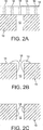
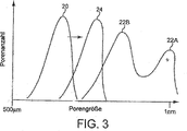
Größenverteilungen von Dieselteilchen haben einen gut ermittelten biomodalen Charakter, der den Teilchenkernbildungs- und Teilchenagglomerationsmechanismen entspricht, wobei die entsprechenden Teilchentypen als Kernmodus bzw. Akkumulationsmodus bezeichnet werden (siehe
Es wird angenommen, dass Kernmodusteilchen hauptsächlich aus flüchtigen Kondensaten (Kohlenwasserstoffen, Schwefelsäure, Salpetersäure usw.) bestehen und wenig festes Material wie Asche und Kohlenstoff enthalten. Akkumulationsmodusteilchen sollen Feststoffe (Kohlenstoff, Metallasche usw.) im Gemisch mit Kondensaten und adsorbiertem Material (schwere Kohlenwasserstoffe, Schwefelspezies, Stickoxidderivate usw.) umfassen. Es wird nicht davon ausgegangen, dass Grobmodusteilchen während des Dieselverbrennungsprozesses erzeugt werden und durch Mechanismen, wie zum Beispiel Ablagerung und anschließendes Wiedermitreißen von Teilchenmaterial von den Wänden eines Motorzylinders, Abgassystems oder des Teilchensammelsystems gebildet werden können. Die Beziehung zwischen diesen Modi ist in
Die Zusammensetzung von Kernteilchen kann sich mit Motorbetriebsbedingungen, Umweltbedingungen (insbesondere Temperatur und Luftfeuchtigkeit), Verdünnungs- und Probennahmesystembedingungen ändern. Laborarbeit und Theorie haben gezeigt, dass der Großteil der Kernmodus-Bildung und des Kernmodus-Wachstums in einem niedrigen Verdünnungsverhältnisbereich auftritt. In diesem Bereich führt die Gas-zu-Teilchen-Umwandlung von flüchtigen Teilchen-Vorläufern, wie schweren Kohlenwasserstoffen und Schwefelsäure, zu einer gleichzeitigen Kernbildung und einem Wachstum des Kernmodus und einer Adsorption an existierende Teilchen im Akkumulationsmodus. Labortests (siehe z. B.
Generell begünstigen eine geringe Temperatur, niedrige Verdünnungsverhältnisse, hohe Luftfeuchtigkeit und lange Verweilzeiten eine Nanoteilchen-Bildung und ein Nanoteilchen-Wachstum. Studien haben gezeigt, dass Nanoteilchen hauptsächlich aus flüchtigem Material bestehen, wie schweren Kohlenwasserstoffen und Schwefelsäure, bestehen, wobei eine feste Fraktion nur bei sehr hohen Belastungen nachgewiesen wird.In general, low temperature, low dilution ratios, high humidity and long residence times promote nanoparticle formation and nanoparticle growth. Studies have shown that nanoparticles consist mainly of volatile material, such as heavy hydrocarbons and sulfuric acid, with a solid fraction being detected only at very high levels of stress.
Dagegen zeigen die Größenverteilungen von Benzinteilchen beim Austritt aus dem Motor bei Betrieb in einem stationären Zustand eine unimodale Verteilung mit einem Peak bei ungefähr 60–80 nm (siehe z. B.
Eine Teilchenansammlung von Dieselteilchen in einem Dieselteilchenfilter basiert auf dem Prinzip des Abtrennens von gasgetragenen Teilchen aus der Gasphase durch Verwendung einer porösen Barriere. Dieselfilter können definiert werden als Tiefenfilter und/oder Oberflächenfilter. In Tiefenfiltern ist die mittlere Porengröße des Filtermediums größer als der mittlere Durchmesser der gesammelten Teilchen. Die Teilchen werden durch eine Kombination von Tiefenfiltrationsmechanismen einschließlich Diffusionsablagerung (Brownsche Molekularbewegung), Trägheitsablagerung (Aufprall) und Strömungslinienabfangen (Brownsche Molekularbewegung oder Trägheit) auf dem Medium abgeschieden.Particulate accumulation of diesel particulates in a diesel particulate filter is based on the principle of separating gas borne gas phase particles by using a porous barrier. Diesel filters can be defined as depth filters and / or surface filters. In depth filters, the mean pore size of the filter media is greater than the mean diameter of the collected particles. The particles are deposited on the medium by a combination of depth filtration mechanisms including diffusion deposition (Brownian motion), inertial deposition (impact) and flow line interception (Brownian motion or inertia).
Bei Oberflächenfiltern ist der Porendurchmesser des Filtermediums geringer als der Durchmesser des PM, so dass PM durch Sieben abgetrennt wird. Das Abtrennen erfolgt durch eine Anhäufung von gesammeltem Diesel-PM an sich, wobei die Anhäufung im Allgemeinen als ”Filterkuchen” und das Verfahren als ”Kuchenfiltration” bezeichnet werden.For surface filters, the pore diameter of the filter medium is less than the diameter of the PM, so that PM is separated by sieving. The separation is accomplished by an accumulation of collected diesel PM per se, the aggregate generally being referred to as "filter cake" and the process as "cake filtration".
Es ist selbstverständlich, dass Dieselteilchenfilter, wie zum Beispiel keramische Wandstrommonolithen, durch eine Kombination von Tiefenfiltration und Oberflächenfiltration arbeiten können: ein Filterkuchen entwickelt sich bei höheren Rußbeladungen, wenn die Tiefenfiltrationskapazität gesättigt ist und eine teilchenförmige Schicht beginnt, die Filtrationsoberfläche zu bedecken. Die Tiefenfiltration ist durch eine etwas geringere Filtrationseffizienz und einen geringeren Druckabfall als bei der Kuchenfiltration gekennzeichnet.It is understood that diesel particulate filters, such as ceramic wall-flow monoliths, can operate by a combination of depth filtration and surface filtration: a filter cake develops at higher carbon black loadings when the depth filtration capacity is saturated and a particulate layer begins to cover the filtration surface. The depth filtration is characterized by a slightly lower filtration efficiency and a lower pressure drop than cake filtration.
Andere im Stand der Technik vorgeschlagene Techniken zum Abtrennen von Benzin-PM aus der Gasphase umfassen eine Wirbelrückgewinnung.Other techniques proposed in the art for separating gasoline gas PM include vortex recovery.
Die Emmissionsgesetzgebung in Europa vom 1. September 2014 (Euro 6) erfordert eine Kontrolle der Teilchenanzahl, die sowohl von Diesel- als auch von Benzin(fremdgezündet)-Passagierfahrzeugen emittiert werden. Für Benzin-EU-Leichtlastfahrzeuge sind die erlaubten Grenzen die folgenden: 1000 mg/km Kohlenmonoxid; 60 mg/km Stickoxide (NOx); 100 mg/km gesamte Kohlenwasserstoffe (von denen ≤ 68 mg/km Nichtmethankohlenwasserstoffe sind); und 4,5 mg/km Feinstaub ((PM) nur für Direkteinspritzmotoren). Obwohl die Behörden den PM-Anzahlstandard für Euro 6 noch nicht festgesetzt haben, wird weithin davon ausgegangen, dass er auf 6,0 × 10¹¹ pro km festgesetzt wird. Die gegenwärtige Spezifikation basiert auf der Annahme, dass diese Zahl zu gegebener Zeit angenommen wird. The emission legislation in Europe of 1 September 2014 (Euro 6) requires a control of the number of particles emitted by both diesel and gasoline (spark-ignited) passenger vehicles. For gasoline EU light commercial vehicles, the permitted limits are as follows: 1000 mg / km carbon monoxide; 60 mg / km nitrogen oxides (NO x ); 100 mg / km of total hydrocarbons (of which ≤ 68 mg / km are non-methane hydrocarbons); and 4.5 mg / km particulate matter ((PM) only for direct injection engines). Although the authorities have not yet set the PM number standard for Euro 6, it is widely assumed that it will be set at 6.0 × 10 11 per km. The current specification is based on the assumption that this number will be adopted in due course.
In den Vereinigten Staaten wurden keine ähnlichen Emissionsstandards festgesetzt. Jedoch hat das Air Resources Board des Staates von Kalifornien (CARS) kürzlich ein Papier veröffentlicht mit dem Titel ”Preliminary Discussion Paper – Amendments to California's Low-Emission Vehicle (LEV) Regulations for Criteria Pollutants – LEV III” (Voläufiges Disskussionspapier – Änderungen zu den kalifornischen Niedrig-Emissions-Fahrzeug(LEV)-Regelungen für kritische Schadstoffe – LEV III) (Freigabedatum: 8. Februar 2010), in dem ein neuer PM-Standard von zwischen 2 und 4 mg PM/Meile (1,25–2,5 mg PM/km (derzeit 10 mg PM/Meile (6,25 mg PM/km))) vorgeschlagen ist. Das Papier kommentiert das wie folgt: ”Mitarbeiter haben Eingaben von einer Reihe von Herstellern erhalten, die vorschlagen, dass ein Standard von 3 mg PM/Meile (1,88 mg PM/km) von Benzin-Direkteinspritzmotoren erfüllt werden kann, ohne dass die Verwendung von Teilchenfiltern erforderlich ist.” Zusätzlich führt das Papier an, da es scheinbar eine Korrelation zwischen der emittierten PM-Masse und und der emittierten PM-Anzahl gibt: ”Obwohl ein zwingender Anzahlstandard derzeit nicht in Betracht gezogen wird, wird ein optionaler PM-Anzahlstandard von ungefähr 1012 Teilchen/Meile (6,2511 Teilchen/km) in Betracht gezogen (der durch die Hersteller anstelle des PM-Massenstandards gewählt werden kann)”. Da jedoch, da weder der PM-Standard noch der PM-Anzahlstandard bis jetzt durch das CARB festgesetzt worden ist, ist es zu früh, um zu sagen, ob eine Teilchenfiltration für den kalifornischen Fahrzeugmarkt oder den US-Fahrzeugmarkt im Allgemeinen erforderlich ist. Trotzdem ist es möglich, dass bestimmte Fahrzeughersteller Filter wählen werden, um einen Sicherheitsspielraum bei beliebigen Entwicklungsoptionen bei fremdgezündeten Verbrennungsmotoren bieten zu können, die so gewählt sind, dass sie jedweden Standard, der letztendlich festgesetzt wird, erfüllen.In the United States, no similar emission standards were set. However, the Air Resources Board of the State of California (CARS) has recently published a paper entitled "Preliminary Discussion Paper - Amendments to California's Low-Emission Vehicle (LEV) Regulations for Criteria Pollutants - LEV III" (Amended Dissertation Paper - Amendments to the Californian Low Emission Vehicle (LEV) Critical Pollutant Control - LEV III) (Released: 8 February 2010), which introduces a new PM standard of between 2 and 4 mg PM / mile (1,25-2, 5 mg PM / km (currently 10 mg PM / mile (6.25 mg PM / km))). The paper commented as follows: "Employees have received input from a number of manufacturers who suggest that a standard of 3 mg PM / mile (1.88 mg PM / km) can be met by gasoline direct injection engines without the Use of particulate filters. "Additionally, the paper cites as there appears to be a correlation between the emitted PM mass and the emitted PM count:" Although a mandatory number standard is currently not considered, an optional PM Considering the number standard of about 10 12 particles / mile (6.25 11 particles / km) (which can be chosen by the manufacturers instead of the PM mass standard) ". However, since neither the PM standard nor the PM number standard has been set by the CARB so far, it is too early to say whether particulate filtration is generally required for the California vehicle market or the US vehicle market. Nevertheless, it is possible that certain vehicle manufacturers will choose filters to provide safety margin in any development options for spark-ignition internal combustion engines that are chosen to meet any standard ultimately set.
Der neue EURO 6-Emissionsstandard stellt eine Anzahl von herausfordernden Entwicklungsproblemen dar, um die Benzin-Emissionsstandards zu erfüllen. Vor allem, wie ein Filter oder ein Abgassystem mit einem Filter entwickelt werden kann, das die Anzahl der PM-Benzin (Fremdgezündung)-Emissionen reduziert und noch dazu gleichzeitig die Emissionsstandards für Nicht-PM-Schadstoffe, wie z. B. ein oder mehrere Stickstoffoxide (NOx), Kohlenmonoxid (CO) und unverbrannten Kohlenwasserstoff (HCl), alle bei einem akzeptablen Gegendruck, beispielsweise gemäß Messung des maximalen Gegendrucks im Zyklus bei dem EU-Fahrzyklus, erfüllt.The new EURO 6 emissions standard represents a number of challenging development issues to meet gasoline emission standards. In particular, how to develop a filter or an exhaust system with a filter that reduces the number of PM (spark-ignition) emissions and, at the same time, the emission standards for non-PM pollutants, such as. One or more nitrogen oxides (NO x ), carbon monoxide (CO) and unburned hydrocarbon (HCl), all at an acceptable backpressure, for example, as measured by the maximum backpressure in the cycle in the EU drive cycle.
Es ist angedacht, dass das Minimum der Teilchenreduktion für einen Drei-Wege-katalysierten Teilchenfilter, um den Euro 6 PM-Anzahlstandard zu erfüllen, in Relation zu einem äquivalenten Durchflusskatalysator ≥ 50% ist. Zusätzlich sollte gemäß unseren Erfahrungen der Peakgegendruck über den MVEG-B-Fahrzyklus (Mittelwert über drei Tests von ”frisch”) für die Mehrzahl von Passagierfahrzeugen auf < 200 mbar, wie < 180 mbar, < 150 mbar und vorzugsweise < 120 mbar, z. B. < 100 mbar begrenzt sein, da eine gewisse Erhöhung des Gegendrucks für einen Drei-Wege-katalysierten Wandstromfilter in Relation zu einem äquivalenten Durchflusskatalysator unvermeidlich ist.It is envisaged that the minimum of particle reduction for a three-way catalyzed particulate filter to meet the Euro 6 PM number standard is ≥ 50% in relation to an equivalent flow catalyst. In addition, according to our experience, the peak backpressure over the MVEG-B drive cycle (average over three tests of "fresh") for the majority of passenger vehicles should be <200 mbar, such as <180 mbar, <150 mbar, and preferably <120 mbar, e.g. <100 mbar, since some increase in back pressure is unavoidable for a three-way catalyzed wall-flow filter in relation to an equivalent flow-through catalyst.
Wie bereits erwähnt, weist PM, erzeugt durch fremdgezündete Verbrennungsmotoren, einen signifikant höheren Anteil an ultrafeinen Teilchen, bei vernachlässigbarem Akkumulations- und Grobmodus auf, verglichen mit dem durch Diesel(selbstgezündete)-Motoren erzeugten PM und dies stellt Herausforderungen dar, PM aus Abgas von fremdgezündeten Verbrennungsmotoren zu entfernen, um seine Emission in die Atmosphäre zu verhindern. Da insbesondere ein Großteil des PM aus einem Verbrennungsmotor mit Fremdzündung relativ klein ist im Vergleich zu der Größenverteilung für Diesel-PM, ist es praktisch nicht möglich, ein Filtersubstrat zu verwenden, das eine oberflächenartige Kuchenfiltration von PM aus fremdgezündeten Motoren fördert, da die relativ kleine mittlere Porengröße des Filtersubstrats, die erforderlich wäre, einen unpraktisch hohen Gegendruck im System erzeugen würde.As already mentioned, PM produced by spark-ignited internal combustion engines has a significantly higher proportion of ultrafine particles in negligible accumulation and coarse mode compared to PM produced by diesel (self-ignited) engines, and this presents challenges to PM from exhaust gas to remove spark-ignition internal combustion engines to prevent its emission into the atmosphere. In particular, since a majority of the PM from a spark-ignition internal combustion engine is relatively small compared to the size distribution for diesel PM, it is practically not possible to use a filter substrate that promotes surface-like cake filtration of PM from spark-ignition engines since the relatively small average pore size of the filter substrate that would be required would produce an impractically high back pressure in the system.
Weiterhin ist es generell nicht möglich, ein konventionelles Wandstromfilter, das für das Einfangen von Dieselfeinstaub entwickelt wurde, zum Fördern einer Oberflächenfiltration von PM aus einem fremdgezündeten Verbrennungsmotor zu verwenden, um die relevanten Emissionsstandards zu erfüllen, da generell weniger Feinstaub in fremdgezündeten Verbrennungsmotoren ist, so dass eine Bildung eines Rußkuchens weniger wahrscheinlich ist. Ferner sind die Temperaturen von Abgasen fremdgezündeter Verbrennungsmotoren generell höher, was zu einer schnelleren Entfernung von PM durch Oxidation führen kann, wodurch eine erhöhte PM-Entfernung durch Kuchenfiltration verhindert wird. Eine Tiefenfiltration von fremdgezündetem PM in einem konventionellen Diesel-Wandstromfilter ist auch schwierig, da der PM signifikant kleiner ist als die Porengröße des Filtermediums. Somit wird bei Normalbetrieb ein unbeschichtetes konventionelles Dieselwandstromfilter eine geringere Filtrationseffizienz haben, wenn es bei einem fremdgezündeten Verbrennungsmotor statt bei einem selbstzündenden Verbrennungsmotor verwendet wird.Furthermore, it is generally not possible to use a conventional wall-flow filter developed for trapping diesel particulate matter to promote surface filtration of PM from a spark-ignited internal combustion engine to meet the relevant emissions standards, since there is generally less particulate matter in spark-ignition internal combustion engines that formation of a soot cake is less likely. Furthermore, the temperatures of exhaust gases of spark-ignited internal combustion engines generally higher, which can result in faster removal of PM by oxidation, thereby preventing increased PM removal by cake filtration. Depth filtration of spark-ignited PM in a conventional diesel wall-flow filter is also difficult because the PM is significantly smaller than the pore size of the filter medium. Thus, in normal operation, an uncoated conventional diesel wallflow filter will have lower filtration efficiency when used in a spark-ignited internal combustion engine rather than a self-igniting internal combustion engine.
Eine weitere Schwierigkeit ist das Kombinieren von Filtrationseffizienz mit einer Washcoat-Beladung, z. B. eines Katalysators zum Erfüllen von Emissionsstandards für Nicht-PM-Schadstoffe, bei akzeptablem Gegendruck. Dieselwandstrompartikelfilter in kommerziell verfügbaren Fahrzeugen haben derzeit eine mittlere Porengröße von ungefähr 13 μm. Allerdings haben wir festgestellt, dass das Beschichten eines Filters dieses Typs mit einem Washcoat bei einer ausreichenden Katalysatorbeladung, wie sie zum Beispiel in
Es ist möglich, die Länge des Substrats zu reduzieren, um den Filtergegendruck zu reduzieren. Allerdings gibt es ein endliches Niveau, unter dem der Gegendruck ansteigt, wenn die Filterlänge reduziert wird. Geeignete Filterlängen für Filter gemäß der vorliegenden Erfindung sind von 2–12 Zoll lang; vorzugsweise 3–6 Zoll lang. Querschnitte können rund sein. Bei unserer Entwicklungsarbeit haben wir Filter mit einem Durchmesser von 4,66 und 5,66 Zoll verwendet. Jedoch kann der Querschnitt auch durch den Raum im Fahrzeug vorgegeben sein, in den das Filter passen soll. Für Filter, die in der sogenannten direkt gekoppelten Position, z. B. innerhalb von 50 cm von dem Motorabgaskrümmer entfernt, angeordnet sind, wo der Raum begrenzt ist, können elliptische oder ovale Filterquerschnitte in Erwägung gezogen werden. Wie man annehmen würde, nimmt der Gegendruck auch mit der Washcoat-Beladung und Ruß-Beladung zu.It is possible to reduce the length of the substrate to reduce the filter back pressure. However, there is a finite level below which the backpressure increases as the filter length is reduced. Suitable filter lengths for filters according to the present invention are from 2 to 12 inches long; preferably 3-6 inches long. Cross sections can be round. In our development work, we have used filters with a diameter of 4.66 and 5.66 inches. However, the cross section can also be determined by the space in the vehicle in which the filter should fit. For filters that are in the so-called directly coupled position, z. B. are located within 50 cm of the engine exhaust manifold, where the space is limited, elliptical or oval filter cross-sections can be considered. As one would expect, backpressure also increases with washcoat loading and carbon black loading.
Es hat eine Anzahl von jüngsten Bemühungen zur Kombination von TWCs mit Filtern gegeben, um die Euro 6 Emissionsstandards zu erfüllen.There have been a number of recent efforts to combine TWCs with filters to meet Euro 6 emissions standards.
Unsere
Eine praktische Schwierigkeit mit Filtern zur Filterung von Feinstaub aus fremdgezündeten Verbrennungsmotoren besteht darin, dass der Raum in einem Passagierfahrzeug limitiert sein kann und das Filter in einer kühleren so genannten ”Unterboden”-Anordnung in geschlungener Form unter dem Fahrzeugunterkörper angeordnet sein müsste. Oftmals gibt es nicht ausreichend Raum in einem Fahrzeug, um ein Filter an einem wärmeren Ort etwas näher an dem Motorkrümmer (die sogenannte direkt gekoppelte Anordnung) anzuordnen, und auf jeden Fall kann die relativ hohe thermische Masse des Filters verhindern, dass der Katalysator ausreichend rasch nach einem Kaltstart des Motors anspringt. Dies ist wichtig, da die Gesetzgebung Fahrzeugemissionen über einen definierten Fahrzyklus bestimmt. Die meisten Schadstoffemissionen eines Fahrzeugs mit fremdgezündetem Verbrennungsmotor entstehen bei dem Testzyklus in den ersten zehn Sekunden nach dem Kaltstart. Ist ein TWC nicht schnell genug nach einem Kaltstart aktiv, kann dies den Unterschied zwischen Bestehen und Durchfallen bei dem relevanten Emissionsstandard über einen Fahrzyklus als Ganzes bedeuten.A practical difficulty with filters for filtering particulate matter from spark-ignited internal combustion engines is that the space in a passenger vehicle may be limited and the filter in a cooler so-called "underbody" arrangement in a looped form should be located below the vehicle body. Often, there is not enough room in a vehicle to place a filter in a warmer location a little closer to the engine manifold (the so-called direct coupled arrangement), and in any event, the relatively high thermal mass of the filter can prevent the catalyst from accelerating sufficiently quickly after a cold start of the engine starts. This is important because the legislation determines vehicle emissions over a defined driving cycle. Most pollutant emissions of a spark-ignition internal combustion engine occur during the test cycle in the first ten seconds after the cold start. If a TWC is not fast enough after a cold start, this can mean the difference between passing and failing at the relevant emission standard over a drive cycle as a whole.
Anspringen kann definiert werden als die Temperatur, bei der ein Katalysator eine Reaktion mit einer gewünschten Umwandlungsaktivität katalysiert. Zum Beispiel ist „CO T50” eine Temperatur, bei der ein bestimmter Katalysator die Umwandlung von Kohlenmonoxid in einem Zufuhrgas mit einer Effizienz von mindestens 50% beispielsweise in CO2 bewirkt. In ähnlicher Weise ist „HC T80” die Temperatur, bei der Kohlenwasserstoff, zum Beispiel ein bestimmter Kohlenwasserstoff wie Oktan oder Propen, mit einer Effizienz von 80% oder mehr z. B. in Wasserdampf und CO2 umgewandelt wird.Popping can be defined as the temperature at which a catalyst catalyzes a reaction having a desired conversion activity. For example, "CO T 50 " is a temperature at which a particular catalyst causes the conversion of carbon monoxide in a feed gas with an efficiency of at least 50%, for example, in CO 2 . Similarly, "HC T 80 " is the temperature at which hydrocarbons, for example, a particular hydrocarbon such as octane or propene, have an efficiency of 80% or more, e.g. B. is converted into water vapor and CO 2 .
In der Praxis enthalten daher Abgassysteme für Fahrzeugverbrennungsmotoren mit Fremdzündung, die derzeit auf dem Markt sind, einen TWC mit einer relativ geringen thermische Masse, der ein Durchflussmonolithsubstrat umfasst, das in einer direkt gekoppelten Position angeordnet ist.In practice, therefore, exhaust systems for spark-ignition vehicle combustion engines currently on the market include a relatively low thermal mass TWC comprising a flow-through monolith substrate disposed in a directly coupled position.
Wir haben jedoch festgestellt, dass, wenn ein mit einem TWC katalysiertes Filter an einem Fahrzeugunterboden und stromab zu einem kommerziell erhältlichen direkt gekoppelten (Durchfluss-)TWC angeordnet ist, die Temperatur in dem Filter unzureichend zuverlässig ist, um Feinstaub in Testzyklen oder bei realen Fahrbedingungen zu verbrennen. Erste Hinweise lassen vermuten, dass Fremdzündungs-PM in Sauerstoff bei geringeren Temperaturen als Diesel-PM zu verbrennt. Nun haben wir jdeoch festgestellt, dass Filtertemperaturen von > 500°C erforderlich sind, um Feinstaub von fremdgezündeten Verbrennungsmotoren zu verbrennen. Es ist möglich, intermittierend zusätzlichen Kohlenwasserstoff in das Abgas zu injizieren, entweder über ein Motormanagement von im Zylinder befindlichen Kraftstoffinjektoren oder direkt in das Abgas, um die Temperatur in dem Filter zu erhöhen oder um andere Mittel, wie einen elektrisch beheizten Katalysator in dem Filter zu verwenden. Jedoch sind solche Lösungen teuer, technisch kompliziert und führen letztlich zu einer Kraftstoffeinbuße für den Fahrer, d. h. zu einem erhöhten Kraftstoffverbrauch.However, we have found that when a TWC catalyzed filter is placed on a vehicle underbody and downstream of a commercially available direct coupled (flow) TWC, the temperature in the filter is insufficiently reliable to allow particulate matter in test cycles or in real driving conditions to burn. Initial evidence suggests that spark ignition PM burns in oxygen at lower temperatures than diesel PM. However, we have now found that filter temperatures of> 500 ° C are required to burn particulate matter from spark-ignition internal combustion engines. It is possible to inject additional hydrocarbon intermittently into the exhaust gas either via engine management of in-cylinder fuel injectors or directly into the exhaust to increase the temperature in the filter or by other means such as an electrically heated catalyst in the filter use. However, such solutions are expensive, technically complicated and ultimately lead to a fuel penalty for the driver, d. H. to an increased fuel consumption.
Wir haben nun sehr überraschend festgestellt, dass es möglich ist, ein Abgassystem für einen Fahrzeugverbrennungsmotor mit Fremdzündung zu entwickeln, bei dem die Filtertemperatur Temperaturen erreicht, die ausreichen, um Feinstaub passiv während wenigstens eines Teils eines gesetzgeberischen Fahrzyklus zu verbrennen oder um wenigstens die Frequenz von aktiven Interventionen zur Erhöhung der Filtertemperatur, z. B. durch Injizieren von zusätzlichem Kohlenwasserstoff, signifikant zu reduzieren.We have now found, quite surprisingly, that it is possible to develop an exhaust system for a spark-ignition vehicle engine, wherein the filter temperature reaches temperatures sufficient to burn particulate matter passively during at least part of a legislative drive cycle, or at least the frequency of active interventions to increase the filter temperature, z. B. by injecting additional hydrocarbon, to reduce significantly.
Gemäß einem Aspekt liefert die Erfindung ein Abgassystem für einen Fahrzeugverbrennungsmotor mit Fremdzündung, das ein Filter zum Filtern von Feinstaub aus von dem Motor emittierten Abgas, wobei das Filter ein poröses Substrat enthält, das Einlassoberflächen und Auslassoberflächen aufweist, wobei die Einlassoberflächen von den Auslassoberflächen durch eine poröse Struktur getrennt sind, die Poren einer ersten mittleren Porengröße enthält, wobei das poröse Substrat mit einem Drei-Wege-Katalysator-Washcoat beschichtet ist, der eine Vielzahl von festen Partikeln umfasst, wobei die poröse Struktur des washcoatbeschichteten porösen Substrats Poren einer zweiten mittleren Porengröße enthält und wobei die zweite mittlere Porengröße kleiner als die erste mittlere Porengröße ist, und einen Drei-Wege-Katalysator-Washcoat, der auf einem separaten Substratmonolithen stromauf des Filters angeordnet ist, umfasst, wobei eine Masse des Drei-Wege-Katalysator-Washcoats auf dem stromaufseitigen Substratmonolithen ≤ 75% der Gesamtmasse des Drei-Wege-Katalysator-Washcoats in dem System ist.In one aspect, the invention provides an exhaust system for a spark-ignited vehicle engine that includes a filter for filtering particulate matter from exhaust emitted from the engine, the filter including a porous substrate having inlet surfaces and outlet surfaces, wherein the inlet surfaces are separated from the outlet surfaces porous structure having pores of a first average pore size, wherein the porous substrate is coated with a three-way catalyst washcoat comprising a plurality of solid particles, wherein the porous structure of the washcoat-coated porous substrate having pores of a second average pore size and wherein the second average pore size is smaller than the first average pore size, and a three-way catalyst washcoat disposed on a separate substrate monolith upstream of the filter, wherein a mass of the three-way catalyst washcoat on the st Römemseitigen substrate monoliths ≤ 75% of the total mass of the three-way catalyst washcoat in the system.
Die drei Wege, auf denen die Erfindung in die Praxis umgesetzt werden kann, umfassen erstens die Verwendung eines Substratmonolithen mit einem kleineren Volumen als das, das normalerweise für einen stromaufseitigen Substratmonolithen in einem Abgassystem für einen Fahrzeugverbrennungsmotor mit Funkenzündung benutzt wird, wobei die gleiche TWC-Washcoat-Beladung verwendet wird, die normalerweise verwendet wird, d. h. größer als insgesamt ungefähr 3 gin–3, entweder in einer Ausgestaltung als einzelne Schicht oder als mehrere Schichten. Gegenwärtig weisen die verwendeten stromaufseitigen Substratmonolithen etwa 60–100% des Motorhubraums oder mehr auf, so dass Substratmonolithen von < 60% des Motorhubraums, wie z. B. < 55%, 50% oder 45% des Motorhubraums, die mit einer Washcoat-Beladung von mehr als etwa 3 gin–3 beschichtet sind, anschauliche Beispiele für katalytisierte stromaufseitige Substratmonolithen sind, die in der vorliegenden Erfindung Anwendung finden. Es ist ebenfalls möglich, dass der stromaufseitige Substratmonolith zwei Teile umfasst, einen stromaufseitigen Teil und einen stromabseitigen Teil, wobei jeder Teil eine unterschiedliche Washcoat-Beladung, Edelmetallbeladung und/oder Volumen aufweist. Das letztere Zwei-Teile-Konzept fällt ebenfalls unter den Umfang der vorliegenden Erfindung.Firstly, the three ways in which the invention can be practiced involve the use of a substrate monolith having a smaller volume than that normally used for an upstream substrate monolith in an exhaust system for a spark ignition vehicle engine, the same TWC being used. Washcoat loading is used normally greater than a total of about 3 gin -3 , either in one embodiment as a single layer or as multiple layers. At present, the used upstream substrate monoliths have about 60-100% of the engine displacement or more, so that substrate monoliths of <60% of the engine displacement such. <55%, 50% or 45% of engine displacement coated with a washcoat loading of greater than about 3 gin -3, are illustrative examples of catalyzed upstream substrate monoliths useful in the present invention. It is also possible that the upstream substrate monolith comprises two parts, an upstream part and a downstream part, each part having a different washcoat loading, noble metal loading and / or volume. The latter two part concept is also within the scope of the present invention.
In einer ersten Anordnung kann die axiale Länge des stromaufseitigen Substratmonolithen kürzer sein als bei kommerziell erhältlichen direkt gekoppelten Substratmonolithen (manchmal im Stand der Technik als „Slice” bezeichnet) in Kombination mit einer relativ hohen Washcoat-Beladung auf dem Drei-Wege-Katalysator-Filtersubstrat.In a first arrangement, the axial length of the upstream substrate monolith may be shorter than commercially available directly coupled substrate monoliths (sometimes referred to in the art as a "slice") in combination with a relatively high washcoat loading on the three-way catalyst filter substrate ,
Zweitens kann der stromaufseitige Substratmonolith die gleiche Größe oder eine ähnliche Größe bezogen auf eine Größe des stromaufseitigen Substratmonolithen, die normalerweise in einem Abgassystem für einen Fahrzeugmotor mit Funkenzündung verwendet wird, aufweisen, d. h. etwa 60–100% des Motorhubraumes oder mehr ausmachen, jedoch ist die verwendete Washcoat-Beladung geringer als die, die in einem normalen stromaufseitigen Substratmonolithen verwendet wird, d. h. insgesamt < 3 g in–3, beispielsweise < 2,75 g in–3, < 2,5 g in–3 oder < 2 g in–3, entweder in einer Konfiguration in Form einer einzelnen Schicht oder in Konfiguration mehrerer Schichten.Second, the upstream-side substrate monolith may have the same size or a similar size with respect to a size of the upstream-side substrate monolith normally used in an exhaust system for a spark-ignition vehicle engine, that is, about 60-100% of the engine displacement or more, however washcoat loading used less than that used in a normal upstream monolith substrate, ie a total of <3 g in -3, for example <2.75 g in -3, <2.5 g in -3 or <2 g in - 3 , either in a single layer configuration or in multiple layer configuration.
Drittens kann der TWC zur Verwendung in dem stromaufseitigen Substratmonolithen ein inhärent weniger aktiver Washcoat als der typischerweise in einem Abgassystem für einen Fahrzeugmotor mit Funkenzündung verwendete sein, z. B. eine geringere Gesamt-Platingruppenmetallbeladung aufweisen oder, wenn zwei oder mehr Platingruppenmetalle verwendet werden, kann das Gewichtsverhältnis des einen oder der mehreren der vorhandenen Platingruppenmetalle niedriger sein relativ zu dem einen oder den mehreren anderen vorhandenen Platingruppenmetallen und/oder die Zusammensetzung kann eine geringere sauerstoffspeichernde Aktivität, beispielsweise eine geringere Beladung an Mischoxid auf der Basis von Cer und Zirkonium aufweisen.Third, the TWC for use in the upstream substrate monolith may be an inherently less active washcoat than that typically used in an exhaust system for a spark ignition vehicle engine, e.g. For example, if lower total platinum group metal loading is used, or if two or more platinum group metals are used, the weight ratio of one or more of the platinum group metals present may be lower relative to the one or more other platinum group metals present and / or the composition may have lower oxygen storage Activity, for example, have a lower loading of mixed oxide based on cerium and zirconium.
Selbstverständlich ist die Verwendung einiger Variationen von zwei oder mehr der obigen drei Optionen möglich.Of course, it is possible to use some variations of two or more of the above three options.
In Ausführungsformen ist die Masse des TWC-Washcoats auf dem stromaufseitigen Substratmonolithen ≤ 70%, wie z. B. ≤ 65%, ≤ 60% oder ≤ 55% der Gesamtmasse des TWC-Washcoats in dem System.In embodiments, the mass of the TWC washcoat on the upstream substrate monolith is ≤ 70%, such as. ≤ 65%, ≤ 60% or ≤ 55% of the total weight of the TWC washcoat in the system.
Die Erfindung basiert auf der Feststellung, dass durch Herstellung eines weniger effizienten stromaufseitigen TWC genügend Schadstoffe (CO, unverbrannte Kohlenwasserstoffe, NOx etc.) durchschlüpfen können, um mit dem Drei-Wege-katalysierten Filter in Kontakt zu gelangen. Die katalytische Umwandlung der verbleibenden Schadstoffe auf dem Drei-Wege-katalysierten Filter erzeugen eine Wärme, die die Filtertemperatur erhöht, wodurch die Filtertemperatur ausreichend erhöht wird, so dass Feinstaub auf oder in dem Filter verbrennt. Es wird aus der vorhergehenden Diskussion deutlich, dass eine derartige Anordnung industriellen Normen in diesem technischen Gebiet intuitiv widerspricht, da ein direkt gekoppelter TWC dafür vorgesehen ist, Schadstoffe nach einem Kaltstart so schnell und effektiv wie möglich zu behandeln. Die Wirksamkeit dieses Prinzips kann durch Computermodelle veranschaulicht werden (siehe Beispiel 8).The invention is based on the discovery that sufficient pollutants can be prepared by producing a less efficient upstream TWC (CO, unburned hydrocarbons, NO x, etc.) by slip to go with the three-way catalyzed filter in contact. Catalytic conversion of the remaining pollutants on the three-way catalyzed filter generates heat that increases the filter temperature, thereby increasing the filter temperature sufficiently to cause particulate matter to burn on or in the filter. It will be apparent from the foregoing discussion that such an arrangement is intuitively contrary to industrial standards in this technical field because a directly coupled TWC is intended to treat pollutants as quickly and effectively as possible after a cold start. The effectiveness of this principle can be illustrated by computer modeling (see Example 8).
Die Erfindung kann auch funktionell definiert werden, wie durch Definieren des stromaufseitigen Substratmonolithen dahingehend, dass er so ausgestaltet ist, dass ausreichend Reaktionsteilnehmergas durchschlüpfen kann, dass das Drei-Wege-katalysierte Filter, das stromabseitig angeordnet ist, die Filtertemperatur um z. B. > 50°C bei einer Filtereinlassgastemperatur von 400°C, relativ zu einem normal ausgebildeten direkt gekoppelten TWC erhöht; oder wobei der TWC auf dem stromaufseitigen Substratmonolithen so ausgebildet ist, dass Schadstoffe mit einer Effizienz von < 80%, beispielsweise < 75%, < 70%, < 65% oder < 60% umgewandelt werden. Es ist davon auszugehen, dass eine oder alle der obigen alternativen Definitionen die beanspruchte Definition ergänzen können, um eine explizitere Unterscheidung zum Stand der Technik zu liefern.The invention may also be functionally defined, such as by defining the upstream substrate monolith to be such that sufficient reactant gas can pass through, such that the three-way catalyzed filter disposed downstream reduces the filter temperature by e.g. B.> 50 ° C at a filter inlet gas temperature of 400 ° C, relative to a normally formed directly coupled TWC increases; or wherein the TWC on the upstream substrate monolith is configured to convert pollutants having an efficiency of <80%, for example <75%, <70%, <65% or <60%. It is to be understood that any or all of the above alternative definitions may supplement the claimed definition to provide a more explicit distinction from the prior art.
Es wird davon ausgegangen, dass der separate, stromauf des Filters angeordnete Substratmonolith vorzugsweise ein Durchflusssubstratmonolith ist, z. B. eines keramischen oder metallischen Aufbaus. Jedoch können, wenn gewünscht, auch andere Substratmonolithen als Durchflussmonolithen verwendet werden, z. B. partielle Filter (siehe z. B.
Es wird davon ausgegangen, dass die Masse des TWC-Washcoats auf dem stromaufseitigen Substratmonolith relativ zu der Gesamtmasse des TWC-Washcoats in dem System definiert ist. Dies ist beabsichtigt, um Anordnungen zu umfassen, bei denen mehr als ein Substratmonolith zusätzlich zu dem Filter einen TWC-Washcoat trägt.. Allerdings ist in bevorzugten Ausführungsformen die Masse des TWC-Washcoats auf dem stromaufseitigen Substratmonolith bezogen auf die Gesamtmasse des TWC-Washcoats in dem Filter plus dem stromaufseitigen Substratmonolith definiert. It is believed that the mass of the TWC washcoat on the upstream substrate monolith is defined relative to the total mass of the TWC washcoat in the system. This is intended to include arrangements in which more than one substrate monolith carries a TWC washcoat in addition to the filter. However, in preferred embodiments, the weight of the TWC washcoat on the upstream substrate monolith is based on the total weight of the TWC washcoat the filter plus the upstream substrate monolith.
Fremdgezündete Verbrennungsmotoren zur Verwendung gemäß diesem Aspekt der Erfindung können mit Benzin, Benzin im Gemisch mit Sauerstoffverbindungen einschließlich Methanol und/oder Ethanol, flüssigem Erdölgas oder verdichtetem Erdgas betankt werden.Foreign-fired internal combustion engines for use in this aspect of the invention may be fueled with gasoline, gasoline mixed with oxygenates including methanol and / or ethanol, liquid petroleum gas, or compressed natural gas.
Frühe Hinweise sind, dass die vorliegende Erfindung fähig ist, die Teilchenzahlemissionen von fremdgezündeten Verbrennungsmotoren um > 30%, beispielsweise > 50%, z. B. > 80% oder auch > 90% bei einem akzeptablen Gegendruck zu reduzieren.Early indications are that the present invention is able to reduce the particle count emissions of spark-ignition internal combustion engines by> 30%, for example> 50%, e.g. B.> 80% or> 90% at an acceptable back pressure to reduce.
Die mittlere Porengröße kann mittels Quecksilber-Porosimetrie bestimmt werden.The mean pore size can be determined by means of mercury porosimetry.
Es wird davon ausgegangen, dass der Nutzen von Filtern zur Verwendung in der Erfindung im Wesentlichen unabhängig von der Porosität des Substrates ist. Die Porosität ist ein Maß des Prozentsatzes des Hohlraums in einem porösen Substrat und steht in Verbindung mit dem Gegendruck in einem Abgassystem. Generell gilt, je geringer die Porosität ist, desto höher ist der Gegendruck. Dennoch ist die Porosität der Filter zur Verwendung in der vorliegenden Erfindung typischerweise > 40% oder > 50% und Porositäten von 45–75%, beispielsweise 50–65% oder 55–60%, können mit Vorteilen verwendet werden. Die mittlere Porengröße des washcoatbeschichteten porösen Substrates ist für die Filtration wichtig. So ist es möglich, ein poröses Substrat mit einer relativ hohen Porosität zu haben, das ein schlechtes Filter ist, da die mittlere Porengröße ebenfalls relativ groß ist.It is believed that the benefit of filters for use in the invention is substantially independent of the porosity of the substrate. The porosity is a measure of the percentage of the void in a porous substrate and is related to the back pressure in an exhaust system. In general, the lower the porosity, the higher the back pressure. Nevertheless, the porosity of the filters for use in the present invention is typically> 40% or> 50% and porosities of 45-75%, for example 50-65% or 55-60%, can be used to advantage. The average pore size of the washcoat-coated porous substrate is important for filtration. Thus, it is possible to have a porous substrate having a relatively high porosity, which is a poor filter, since the average pore size is also relatively large.
Das poröse Substrat kann ein Metall sein, wie zum Beispiel ein gesintertes Metall, oder eine Keramik, z. B. Siliicumcarbid, Cordierit, Aluminiumnitrid, Siliciumnitrid, Aluminiumtitanat, Aluminiumoxid, Mullit, zum Beispiel nadelförmiges Mullit (siehe z. B.
Gründe, die zum Beschichten eines Wandstromfilters für eine Dieselanwendung anregen, sind typischerweise unterschiedlich von denen der vorliegenden Erfindung. Bei Dieselanwendungen ist ein Washcoat verwendet, um katalytische Komponenten in das Filtersubstrat einzuführen, z. B. Katalysatoren für ein Oxidieren von NO in NO2, wobei ein signifikantes Problem auch darin besteht, Gegendruck zu vermeiden, wenn Ruß akkumuliert. Folglich wird ein Ausgleich zwischen der gewünschten katalytischen Aktivität und einem akzeptablen Gegendruck gehalten. Dagegen besteht ein hauptsächlicher Motivationsfaktor für das Beschichten eines porösen Substrats mit einem Washcoat zur Verwendung in der vorliegenden Erfindung darin, sowohl eine gewünschte Filtrationseffizienz als auch eine katalytische Aktivität zu erreichen.Reasons which encourage the coating of a wall-flow filter for a diesel application are typically different from those of the present invention. In diesel applications, a washcoat is used to introduce catalytic components into the filter substrate, e.g. For example, catalysts for oxidizing NO to NO 2 , where a significant problem is also to avoid back pressure as carbon accumulates. Consequently, a balance is maintained between the desired catalytic activity and an acceptable backpressure. In contrast, a major motivating factor for coating a porous washcoat substrate for use in the present invention is to achieve both desired filtration efficiency and catalytic activity.
In einer Ausführungsform beträgt eine erste mittlere Porengröße beispielsweise der Oberflächenporen der porösen Struktur des porösen Filtersubstrats 8 bis 45 μm, zum Beispiel 8 bis 25 μm, 10 bis 20 μm oder 10 bis 15 μm. In besonderen Ausführungsformen ist die erste mittlere Porengröße > 18 μm, wie z. B. von 15 bis 45 μm, 20 bis 45 μm, z. B. 20 bis 30 μm oder 25 bis 45 μm.In one embodiment, a first average pore size, for example, of the surface pores of the porous structure of the porous filter substrate is 8 to 45 μm, for example, 8 to 25 μm, 10 to 20 μm, or 10 to 15 μm. In particular embodiments, the first average pore size is> 18 microns, such as. B. from 15 to 45 microns, 20 to 45 microns, z. B. 20 to 30 microns or 25 to 45 microns.
In Ausführungsformen hat das Filter eine Washcoat-Beladung von > 0,25 g in–3, beispielsweise > 0,5 g in–3) oder ≥ 0,80 g in–3, z. B. 0,80 bis 3,00 g in–3. In bevorzugten Ausführungsformen ist die Washcoat-Beladung > 1,00 g in–3, beispielsweise ≥ 1,2 g in–3, > 1,5 g in–3, > 1,6 g in–3 oder > 2,00 g in–3, oder zum Beispiel 1,6 bis 2,4 g in–3. In speziellen Kombinationen von mittlerer Filterporengröße und Washcoat-Beladungen kombiniert das Filter ein wünschenswertes Niveau an Teilchenfiltration und katalytischer Aktivität bei akzeptablem Gegendruck.In embodiments, the filter has a washcoat loading of> 0.25 g in -3 , for example> 0.5 g in -3 ) or ≥0.80 g in -3 , e.g. B. 0.80 to 3.00 g in -3 . In preferred embodiments, the washcoat loading is> 1.00 g in -3 , for example ≥ 1.2 g in -3 ,> 1.5 g in -3 ,> 1.6 g in -3 or> 2.00 g in -3 , or for example 1.6 to 2.4 g in -3 . In specific combinations of mean filter pore size and washcoat loadings, the filter combines a desirable level of particle filtration and catalytic activity with acceptable backpressure.
In einer ersten bevorzugten Ausführungsform umfasst das Filter einen Oberflächen-Washcoat, wobei eine Washcoat-Schicht die Oberflächenporen der porösen Struktur im Wesentlichen bedeckt und die Poren des washcoatbeschichteten porösen Substrats teilweise durch Räume zwischen den Teilchen (interpartikuläre Poren) in dem Washcoat definiert sind. Das heißt, im Wesentlichen kein Washcoat dringt in die poröse Struktur des porösen Substrats ein. Verfahren zur Herstellung von oberflächenbeschichteten porösen Filtersubstraten umfassen ein Einführen eines Polymers, z. B. von Polyvinylalkohol (PVA), in die poröse Struktur, ein Appliziern eines Washcoats auf das poröse Filtersubstrat einschließlich des Polymers und ein Trocknen, anschließendes Kalzinieren des beschichteten Substrats, um das Polymer auszubrennen. Eine schematische Darstellung der ersten Ausführungsform ist in der
Verfahren zum Beschichten von porösen Filtersubstraten sind einem Fachmann bekannt und schließen ohne Einschränkung das in der
In dieser ersten Ausführungsform beträgt eine mittlere interpartikuläre Porengröße des porösen Washcoats 5,0 nm bis 5,0 μm, wie z. B. 0,1–1,0 μm.In this first embodiment, a mean interparticle pore size of the porous washcoat is 5.0 nm to 5.0 μm, such as. B. 0.1-1.0 microns.
Ein D90 von festen Washcoat-Teilchen in dieser ersten Oberflächenbeschichtungsausführungsform kann größer sein als die mittlere Porengröße des porösen Filtersubstrats und kann in einem Bereich von 10 bis 40 μm, beispielsweise 15 bis 30 μm oder 12 bis 25 μm liegen. ”D90”, wie hier verwendet, definiert eine Teilchengrößenverteilung in einem Washcoat, wobei 90% der vorhandenen Teilchen einen Durchmesser in dem angegebenen Bereich haben. Alternativ liegt in Ausführungsformen die mittlere Größe der festen Washcoat-Teilchen in einem Bereich von 1 bis 20 μm. Es wird davon ausgegangen, dass je breiter der Bereich der Teilchengrößen in dem Washcoat ist, es umso wahrscheinlicher ist, das der Washcoat in die poröse Struktur des porösen Substrats eindringen kann. Der Begriff ”im Wesentlichen dringt kein Washcoat in die poröse Struktur des Substrats ein” sollte daher demgemäß interpretiert werden.A D90 of solid washcoat particles in this first surface coating embodiment may be larger than the average pore size of the porous filter substrate and may be in a range of 10 to 40 μm, for example 15 to 30 μm or 12 to 25 μm. "D90" as used herein defines a particle size distribution in a washcoat wherein 90% of the particles present have a diameter in the indicated range. Alternatively, in embodiments, the average size of the solid washcoat particles ranges from 1 to 20 microns. It is believed that the broader the range of particle sizes in the washcoat, the more likely the washcoat can penetrate into the porous structure of the porous substrate. The term "substantially no washcoat penetrates into the porous structure of the substrate" should therefore be interpreted accordingly.
Gemäß einer zweiten Ausführungsform kann der Washcoat auf die Einlassoberflächen und/oder die Auslassoberflächen und auch innerhalb der porösen Struktur des porösen Substrats aufgetragen sein. Wir glauben, dass eine Oberflächenbeschichtung um eine Porenöffnung bei Einlass- und/oder Auslassoberflächen, wodurch z. B. die Oberflächenporengröße eines blanken Filtersubstrates verengt wird, die Interaktion mit der Feinstaub umfassenden Gasfhase fördert, ohne dass das Porenvolumen wesentlich verringert wird, so dass der Gegendruck nicht signifikant erhöht wird. Das heißt, dass die Poren an einer Oberfläche der porösen Struktur eine Porenöffnung umfassen und der Washcoat eine Verengung von im Wesentlichen allen Porenöffnungen bewirkt. Eine schematische Darstellung der zweiten Ausführungsform ist in der
Verfahren zur Herstellung eines Filters gemäß der zweiten Ausführungsform können eine geeignete Formulierung des Washcoats umfassen, der einem Fachmann bekannt ist, einschließlich einem Einstellen der Viskosität und der Oberflächenbenetzungseigenschaften und einem Anlegen eines geeigneten Vakuums nach einem Beschichten des porösen Substrats (siehe auch
In den ersten und zweiten Ausführungsformen, wobei wenigstens ein Teil des Washcoats auf die Einlass- und/oder Auslassoberflächen des porösen Substrats aufgetragen ist, kann der Washcoat auf die Einlassoberflächen, die Auslassoberflächen oder sowohl auf die Einlass- als auch auf die Auslassoberflächen aufgetragen werden. Zusätzlich kann entweder eines oder sowohl die Einlass- als auch die Auslassoberflächen eine Vielzahl von Washcoat-Schichten umfassen, wobei jede Washcoat-Schicht innerhalb der Vielzahl der Schichten gleich oder unterschiedlich sein kann, z. B. kann die mittlere Porengröße in einer ersten Schicht unterschiedlich zu der einer zweiten Schicht sein. In Ausführungsformen ist der Washcoat, der für die Beschichtung der Auslassoberflächen vorgesehen ist, nicht unbedingt der gleiche wie der für die Einlassoberflächen.In the first and second embodiments wherein at least a portion of the washcoat is applied to the inlet and / or outlet surfaces of the porous substrate, the washcoat may be applied to the inlet surfaces, the outlet surfaces, or both the inlet and outlet surfaces. Additionally, either or both of the inlet and outlet surfaces may comprise a plurality of washcoat layers, wherein each washcoat layer within the plurality of layers may be the same or different, e.g. For example, the average pore size in a first layer may be different than that of a second layer. In embodiments, the washcoat intended for the coating of the outlet surfaces is not necessarily the same as that for the inlet surfaces.
Wenn sowohl Einlass- als auch Auslassoberflächen beschichtet werden, können die Washcoatformulierungen gleich oder verschieden sein. Wenn sowohl die Einlass- als auch die Auslassoberflächen mit Washcoat beschichtet sind, kann die mittlere Porengröße des Washcoats auf den Einlassoberflächen von der mittleren Porengröße des Washcoats auf den Auslassoberflächen verschieden sein. Zum Beispiel kann die mittlere Porengröße des Washcoats auf den Einlassoberflächen kleiner sein als die mittlere Porengröße des Washcoats auf den Auslassoberflächen. Im letzteren Fall kann die mittlere Porengröße des Washcoats auf den Auslassoberflächen größer sein als die mittlere Porengröße des porösen Substrats.If both inlet and outlet surfaces are coated, the washcoat formulations may be the same or different. If both the inlet and outlet surfaces are washcoated, the Average pore size of the washcoat on the inlet surfaces may be different from the average pore size of the washcoat on the outlet surfaces. For example, the average pore size of the washcoat on the inlet surfaces may be less than the average pore size of the washcoat on the outlet surfaces. In the latter case, the average pore size of the washcoat on the outlet surfaces may be greater than the average pore size of the porous substrate.
Obwohl es möglich ist, dass die mittlere Porengröße eines auf die Einlassoberflächen aufgetragenen Washcoats größer ist als die mittlere Porengröße des porösen Substrats, ist es vorteilhaft, einen Washcoat zu haben, der kleinere Poren als das poröse Substrat im Washcoat au Einlassoberflächen aufweist, um jegliche Verbrennungsasche oder jeden Schmutz, der in das poröse Substrat eindringt, zu verhindern oder zu reduzieren.Although it is possible for the average pore size of a washcoat applied to the inlet surfaces to be greater than the average pore size of the porous substrate, it is advantageous to have a washcoat having smaller pores than the porous substrate in the washcoat on inlet surfaces to remove any combustion ash or to prevent or reduce any dirt that enters the porous substrate.
Gemäß einer dritten Ausführungsform sitzt der Washcoat im Wesentlichen im Inneren der porösen Struktur des porösen Substrats, d. h. er durchdringt die poröse Struktur des porösen Substrats. Eine schematische Darstellung dieser dritten Ausführungsform ist in der
In der zweiten und dritten Ausführungsform, wobei wenigstens ein Teil des Washcoats sich in der porösen Struktur befindet, kann die Größe, z. B. die mittlere Größe, der festen Washcoat-Teilchen kleiner sein als die mittlere Porengröße des porösen Filtersubstrats, zum Beispiel im Bereich von 0,1 bis 20 μm, z. B. von 1 bis 18 μm, 1 bis 16 μm, 2 bis 15 μm oder 3 bis 12 μm liegen. In besonderen Ausführungsformen ist die oben genannte Größe der festen Washcoat-Teilchen eine D90 anstelle einer mittleren Größe.In the second and third embodiments, wherein at least a portion of the washcoat is in the porous structure, the size, e.g. Example, the average size, the solid washcoat particles smaller than the average pore size of the porous filter substrate, for example in the range of 0.1 to 20 microns, z. B. from 1 to 18 microns, 1 to 16 microns, 2 to 15 microns or 3 to 12 microns. In particular embodiments, the above size of the solid washcoat particles is a D90 instead of an average size.
In weiteren besonderen Ausführungsformen ist die Oberflächenporosität des Washcoats durch Einschließen von Hohlräumen darin erhöht. Abgaskatalysatoren, die solche Merkmale aufweisen, sind z. B. in unserer
Unter Hohlräumen in der Washcoat-Schicht wird hier verstanden, dass ein Raum in der Schicht existiert, der durch festes Washcoat-Material definiert ist. Hohlräume können beliebige freie Stellen, feine Poren, Tunnelarten (Zylinder, prismatische Säulen), Schlitze etc. umfassen und können durch Einarbeiten eines Materials in eine Washcoat-Zusammensetzung zum Beschichten eines Filtersubstrates, das während des Kalzinierens eines beschichteten Filtersubstrats verbrannt wird, z. B. zerkleinerte Baumwolle oder Materialien, die Poren hervorrufen, die durch Bildung von Gas durch Zersetzung oder Verbrennung hergestellt werden, eingeführt werden. Dort wo Hohlräume vorhanden sind, können die Hohlräume von der mittleren interpartikulären Porengröße die porösen Washcoats verschieden sein, und sollten daher bei der Bestimmung der mittleren interpartikulären Porengröße des porösen Washcoats nicht mitgezählt werden.Hollow spaces in the washcoat layer are understood here to mean that a space exists in the layer which is defined by solid washcoat material. Voids may include any vacancies, fine pores, tunnel types (cylinders, prismatic columns), slots, etc., and may be formed by incorporating a material into a washcoat composition for coating a filter substrate which is burned during calcination of a coated filter substrate, e.g. As crushed cotton or materials that cause pores, which are produced by formation of gas by decomposition or combustion, are introduced. Where voids are present, the voids may differ from the mean interparticle pore size of the porous washcoats and, therefore, should not be counted in determining the mean interparticle pore size of the porous washcoat.
Das mittlere Hohlraumverhältnis des Washcoats kann 5–80% betragen, wohingegen der mittlere Durchmesser der Hohlräume 0,2 bis 500 μm, wie z. B. 10 bis 250 μm betragen kann.The average voids ratio of the washcoat may be 5-80%, whereas the average diameter of the voids is 0.2 to 500 μm, such as e.g. B. may be 10 to 250 microns.
Der Washcoat zur Verwendung in dem Filter der Erfindung ist ein Drei-Wege-katalytischer Washcoat, der in Kombination mit anderen katalytischen Washcoats verwendet werden kann, die aus der Gruppe ausgewählt sind, die aus einer Kohlenwasserstofffalle, einem NOx-Absorber, einem Oxidationskatalysator, einem selektiven katalytischen Reduktions(SCR)-Katalysator, einem mageren NOx-Katalysator und Kombinationen von beliebigen zwei oder mehr davon bestehen. Zum Beispiel sind in bevorzugten Ausführungsformen Einlassoberflächen mit einem TWC-Washcoat beschichtet und die Auslassoberflächen sind mit einem SCR-Washcoat beschichtet. In dieser Anordnung kann ein intermittierendes fettes Laufen des Motors Ammoniak in situ auf dem TWC zur Verwendung bei der Reduzierung von NOx auf dem SCR-Kataysator, der auf den Auslassoberflächen angeordnet ist, erzeugen. Ähnlich kann ein Oxidationskatalysator eine Kohlenwasserstofffallen-Funktionalität umfassen.The washcoat for use in the filter of the invention is a three-way catalytic washcoat, which can be used in combination with other catalytic washcoat selected from the group consisting of a hydrocarbon trap, a NOx absorber, an oxidation catalyst a selective catalytic reduction (SCR) catalyst, a lean NO x catalyst, and combinations of any two or more thereof. For example, in preferred embodiments, inlet surfaces are coated with a TWC washcoat and the outlet surfaces are coated with an SCR washcoat. In this arrangement, intermittent rich running of the engine may generate ammonia in situ on the TWC for use in reducing NO x on the SCR catalyst disposed on the outlet surfaces. Similarly, an oxidation catalyst may include a hydrocarbon trap functionality.
Der katalytische Washcoat, beispielsweise der NOx-Absorber, Oxidationskatalysator, die Kohlenwasserstofffalle und der magere NOx-Katalysator, kann einen oder mehrere Platingruppenmetalle enthalten, insbesondere solche, die aus der Gruppe ausgewählt sind, die aus Platin, Palladium und Rhodium besteht.The catalytic washcoat, such as the NO x absorber, oxidation catalyst, hydrocarbon trap, and lean NO x catalyst, may contain one or more platinum group metals, particularly those selected from the group consisting of platinum, palladium, and rhodium.
NOx-Absorber-Katalysatoren (NACs) sind bekannt, z. B. aus dem
Eine typische NAC-Formulierung umfasst eine katalytische Oxidationskomponente, wie z. B. Platin, eine signifikante Menge, d. h. wesentlich mehr als zur Verwendung als Promotor, beispielsweise als Promotor in einem TWC benötigt wird, einer NOx-Speicherkomponente, wie z. B. Barium, und einen Reduktionskatalysator, z. B. Rhodium. Ein Mechanismus, der allgemein für eine NOx-Speicherung aus einem mageren Abgas für diese Formulierung angegeben ist, ist:
Bei geringeren Sauerstoffkonzentrationen und/oder bei erhöhten Temperaturen werden die Nitratspezies thermodynamisch instabil und zerfallen, wobei NO oder NO2 gemäß der unten aufgeführten Reaktion (4) gebildet wird. In Gegenwart eines passenden Reduktionsmittels werden diese Stickstoffoxide nachfolgend reduziert durch Kohlenmonoxid, Wasserstoff und Kohlenwasserstoffe zu N2 reduziert, was auf dem Reduktionskatalysator stattfinden kann (siehe Reaktion (5)).
In den Reaktionen (2)–(5) oben ist die reaktive Bariumspezies als Oxid gegeben. Dennoch kann davon ausgegangen werden, dass in Gegenwart von Luft das meiste des Bariums in der Form des Carbonats oder möglicherweise des Hydroxids vorliegt. Der Fachmann kann die obigen Reaktionsschemata für die von dem Oxid verschiedenen Bariumspezies entsprechend anpassen.In Reactions (2) - (5) above, the reactive barium species is given as an oxide. Nevertheless, it can be assumed that in the presence of air most of the barium is in the form of the carbonate or possibly of the hydroxide. The person skilled in the art can adapt the above reaction schemes accordingly for the barium species other than the oxide.
Oxidationskatalysatoren fördern die Oxidation von Kohlenmonoxid zu Kohlendioxid und von unverbrannten Kohlenwasserstoffen zu Kohlendioxid und Wasser. Typische Oxidationskatalysatoren umfassen Platin und/oder Palladium auf einem Trägermaterial mit einer hohen spezifischen Oberfläche.Oxidation catalysts promote the oxidation of carbon monoxide to carbon dioxide and unburned hydrocarbons to carbon dioxide and water. Typical oxidation catalysts include platinum and / or palladium on a high specific surface area support material.
Kohlenwasserstofffallen umfassen typischerweise Molekularsiebe und können auch katalysiert sein, z. B. mit einem Platingruppenmetall, wie z. B. Platin oder einer Kombination aus sowohl Platin als auch Palladium.Hydrocarbon traps typically include molecular sieves and may also be catalyzed, e.g. B. with a platinum group metal, such as. Platinum or a combination of both platinum and palladium.
SCR-Katalysatoren können aus einer Gruppe ausgewählt sein, die aus wenigstens einem von Cu, Hf, La, Au, In, V, Lanthaniden und Gruppe-VIII-Übergangsmetallen, wie Fe, aufgetragen auf ein feuerfestes Oxid oder Molekularsieb, besteht. Passende feuerfeste Oxide umfassen Al2O3, TiO2, CeO2, SiO2, ZrO2 und Mischoxide, die zwei oder mehrere davon enthalten. Der nicht-zeolithische Katalysator kann auch Wolframoxid umfassen, z. B. V2O5/WO3/TiO2.SCR catalysts may be selected from the group consisting of at least one of Cu, Hf, La, Au, In, V, lanthanides, and Group VIII transition metals such as Fe applied to a refractory oxide or molecular sieve. Suitable refractory oxides include Al 2 O 3 , TiO 2 , CeO 2 , SiO 2 , ZrO 2 and mixed oxides containing two or more thereof. The non-zeolitic catalyst may also comprise tungsten oxide, e.g. B. V 2 O 5 / WO 3 / TiO 2 .
Magere NOx-Katalysatoren, die manchmal auch als Kohlenwasserstoff-SCR-Katalysatoren bezeichnet werden, DeNOx-Katalysatoren oder gar nicht selektiv katalytische Reduktionskatalysatoren umfassen Pt/Al2O3, Cu-, Pt-, Fe-, Co- oder Ir-ausgetauschtes ZSM-5, protonierte Zeolite wie z. B. H-ZSM-5 oder H-Y Zeolite, Perovskite und Ag/Al2O3. In selektiven katalytischen Reduktionen (SCR) durch Kohlenwasserstoffe (HC) reagiert der HC mit NOx statt mit O2, um gemäß Gleichung (6) Stickstoff, CO2 und Wasser zu bilden:
Die konkurrierende, nicht-selektive Reaktion mit Sauerstoff ist durch Gleichung (7) gegeben:
Daher sind gute HC-SCR-Katalysatoren selektiver für Reaktion (6) als für Reaktion (7). In besonderen Ausführungsformen enthalten die SCR-, Kohlenwasserstofffallen- und mageren NOx-Katalysator-Washcoats wenigstens ein Molekularsieb, wie einen Alumosilikat-Zeolit oder ein SAPO, zum Einfangen von Fremdzündungs-PM. Das wenigstens eine Molekularsieb kann beispielsweise ein klein-, mittel- oder großporiges Molekularsieb sein. Unter einem ”kleinporigen Molekualrsieb” meinen wir hier Molekularsiebe, die eine maximale Ringgröße von 8 enthalten, wie z. B. CHA; unter einem ”mittelporigen Molekularsieb” meinen wir hier ein Molekularsieb, das eine maximale Ringgröße von 10 enthält, wie z. B. ZSM-5; und unter einem ”großporigen Molekularsieb” meinen wir hier ein Molekularsieb, das eine maximale Ringgröße von 12 enthält, wie z. B. Beta. Kleinporige Molekularsiebe sind möglicherweise vorteilhaft zur Verwendung in SCR-Katalysatoren – siehe z. B.
Besondere Molekularsiebe mit Anwendung in der vorliegenden Erfindung sind aus einer Gruppe ausgewählt, die aus AEI, ZSM-5, ZSM-20, ERI einschließlich ZSM-34, Mordenit, Ferrierit, BEA einschließlich Beta, Y, CHA, LEV einschließlich Nu-3, MCM-22 und EU-1 besteht.Particular molecular sieves used in the present invention are selected from the group consisting of AEI, ZSM-5, ZSM-20, ERI including ZSM-34, mordenite, ferrierite, BEA including beta, Y, CHA, LEV including Nu-3, MCM-22 and EU-1 exists.
In Ausführungsformen können die Molekularsiebe unmetallisiert oder mit wenigstens einem Metall, ausgewählt aus einer Gruppe bestehend aus den Gruppen IB, IIB, IIIA, IIIB, VB, VIB, VIB und VIII des Periodensystems, metallisiert sein. Wenn metallisiert, kann das Metall aus der Gruppe ausgewählt sein, die aus Cr, Co, Cu, Fe, Hf, La, Ce, In, V, Mn, Ni, Zn, Ga und den Edelmetallen Ag, Au, Pt, Pd und Rh besteht. Solche metallisierten Molekularsiebe können in einem Prozess zum selektiven Katalysieren der Reduktion von Stickstoffoxiden in Fremdzündungsabgasen unter Verwendung eines Reduktionsmittels verwendet werden. Unter „metallisiert” meinen wir hier, dass Molekularsiebe umfasst sind, die ein oder mehrere Metalle umfassen, die in das Gerüst des Molekularsiebs eingearbeitet sind, z. B. Fe in das Gerüst Beta und Cu in das Gerüst CHA. Wie oben angegeben, wird der Prozess manchmal, wenn das Reduktionsmittel ein Kohlenwasserstoff ist, als ”Kohlenwasserstoff-selektive katalytische Reduktion” (HC-SCR), ”magere NOx-Katalyse” oder ”DeNOx-Katalyse” bezeichnet und spezielle Metalle für diese Anwendung umfassen Cu, Pt, Mn, Fe, Co, Ni, Zn, Ag, Ce, Ga. Kohlenwasserstoff-Reduktionsmittel können auf einem von 2 Wegen in das Abgas über Motormanagementtechniken eingeführt werden, z. B. durch späte Nachinjektion oder durch frühe Nachinjektion (so genannte „Nach-Injektion”).In embodiments, the molecular sieves may be metallized, or metallized with at least one metal selected from the group consisting of Groups IB, IIB, IIIA, IIIB, VB, VIB, VIB and VIII of the Periodic Table. When metallized, the metal may be selected from the group consisting of Cr, Co, Cu, Fe, Hf, La, Ce, In, V, Mn, Ni, Zn, Ga and the noble metals Ag, Au, Pt, Pd and Rh exists. Such metallized molecular sieves may be used in a process for selectively catalyzing the reduction of nitrogen oxides in spark ignition exhaust gases using a reducing agent. By "metallized" we mean here that molecular sieves are included comprising one or more metals incorporated in the framework of the molecular sieve, e.g. For example, Fe in the framework beta and Cu in the framework CHA. As noted above, when the reducing agent is a hydrocarbon, the process is sometimes referred to as "hydrocarbon-selective catalytic reduction" (HC-SCR), "lean NO x catalysis" or "DeNO x catalysis" and special metals for these Applications include Cu, Pt, Mn, Fe, Co, Ni, Zn, Ag, Ce, Ga. Hydrocarbon reductants may be introduced into the exhaust in one of two ways via engine management techniques, e.g. As by late Nachinjektion or by early Nachinjektion (so-called "post-injection").
Ist das Reduktionsmittel ein stickstoffhaltiges Reduktionsmittel (ein so genanntes ”NH3-SCR”), sind Metalle von besonderem Interesse aus einer Gruppe ausgewählt, die aus Ce, Fe und Cu besteht. Passende stickstoffhaltige Reduktionsmittel umfassen Ammoniak. Ammoniak kann in situ beispielsweise während der fetten Regeneration eines stromaufseitig zu einem Filter angeordneten NAC oder durch Kontaktieren eines TWC mit aus dem Motor stammendem fettem Abgas (siehe die Alternativen zu den Reaktionen (4) und (5) oben) erzeugt werden. Alternativ kann das stickstoffhaltige Reduktionsmittel oder ein Vorläufer davon direkt in das Abgas injiziert werden. Passende Vorläufer umfassen Ammoniumformiat, Harnstoff und Ammoniumcarbamat. Ein Zerfallen des Vorläufers zu Ammoniak und anderen Nebenprodukten kann durch hydrothermale oder katalytische Hydrolyse erfolgen.When the reducing agent is a nitrogen-containing reducing agent (a so-called "NH 3 -SCR"), metals of particular interest are selected from a group consisting of Ce, Fe and Cu. Suitable nitrogenous reducing agents include ammonia. For example, ammonia can be generated in situ during rich regeneration of a NAC disposed upstream of a filter or by contacting a TWC with engine-derived rich exhaust (see the alternatives to reactions (4) and (5) above). Alternatively, the nitrogen-containing reducing agent or a precursor thereof may be injected directly into the exhaust gas. Suitable precursors include ammonium formate, urea and ammonium carbamate. Disintegration of the precursor to ammonia and other by-products may be by hydrothermal or catalytic hydrolysis.
Die Zelldichte von Diesel-Wandstromfiltern bei der praktischen Verwendung kann sich von der der Wandstromfilter zur Verwendung in der vorliegenden Erfindung dahingehend unterscheiden, dass die Zelldichte eines Diesel-Wandstromfilters im Allgemeinen 300 Zellen pro Quadratzoll (cpsi) oder weniger, z. B. 100 oder 200 cpsi beträgt, so dass die relativ größeren Diesel-PM-Komponenten in die Einlasskanäle des Filters eindringen können ohne dass sie auf dem festen Frontbereich des Diesel-Teilchenfilters aufprallen, wobei sie zusammenbacken und den Zugang zu den offenen Kanäleverschmutzen, während Wandstromfilter zur Verwendung in der vorliegenden Erfindung bis zu 300 cpsi oder mehr, wie z. B. 350 cpsi, 400 cpsi, 600 cpsi, 900 cpsi oder gar 1200 cpsi aufweisen könnenThe cell density of diesel wall-flow filters in practical use may differ from that of the wall-flow filters for use in the present invention in that the cell density of a diesel wall-flow filter is generally 300 cells per square inch (cpsi) or less, e.g. 100 or 200 cpsi, so that the relatively larger diesel PM components can penetrate into the inlet ports of the filter without impacting the solid front portion of the diesel particulate filter, thereby caking and contaminating access to the open channels Wandstromfilter for use in the present invention up to 300 cpsi or more, such as. 350 cpsi, 400 cpsi, 600 cpsi, 900 cpsi or even 1200 cpsi
Ein Vorteil der Verwendung von höheren Zelldichten ist, dass das Filter einen reduzierten Querschnitt, z. B. Durchmesser, als das Dieselpartikelfilter haben kann, was ein hilfreicher, praktischer Vorteil ist, der die Entwicklungsoptionen für die Anordnung von Abgassystemen im Fahrzeug erhöht. An advantage of using higher cell densities is that the filter has a reduced cross-section, e.g. B. diameter, than the diesel particulate filter may have, which is a helpful, practical advantage that increases the development options for the arrangement of exhaust systems in the vehicle.
Gemäß einem anderen Aspekt liefert die Erfindung einen Verbrennungsmotor mit Fremdzündung mit einem Abgassystem gemäß der Erfindung und ein Fahrzeug, das einen solchen fremdgezündeten Verbrennungsmotor umfasst. In einer bevorzugten Ausführungsform ist der fremdgezündete Verbrennungsmotor ein fremdgezündeter Verbrennungsmotor mit Direkteinspritzung.In another aspect, the invention provides a spark-ignition internal combustion engine having an exhaust system according to the invention and a vehicle including such a spark-ignition internal combustion engine. In a preferred embodiment, the spark-ignited internal combustion engine is a spark-ignition internal combustion engine with direct injection.
In einem weiteren Aspekt liefert die Erfindung ein Verfahren zum Einfangen und Verbrennen von Feinstaub (PM) aus Abgas, das aus einem Verbrennungsmotor mit Fremdzündung emittiert wird, durch Tiefenfiltration, wobei das Verfahren ein Lenken des PM enthaltenden Abgases in ein Abgassystem, ein Kontaktieren des PM enthaltenden Abgases mit einem Drei-Wege-Katalysator-Washcoat, der auf einem Substratmonolith angeordnet ist, in dem Abgassystem, ein Kontaktieren des PM enthaltenden Abgases mit einem Filter in dem Abgassystem stromabseitig des Drei-Wege-Katalysator-Substratmonolithen, wobei das Filter ein poröses Substrat umfasst, das Einlass- und Auslassoberflächen aufweist, wobei die Einlassoberflächen von den Auslassoberflächen durch eine poröse Struktur getrennt sind, die Poren einer ersten mittleren Porengröße aufweist, wobei das poröse Substrat mit einem Drei-Wege-Katalysator-Washcoat beschichtet ist, der eine Vielzahl von festen Teilchen umfasst, wobei die poröse Struktur des washcoatbeschichteten porösen Substrats Poren einer zweiten mittleren Porengröße enthält und wobei die zweite mittlere Porengröße kleiner ist als die erste mittlere Porengröße, wobei die Masse des Drei-Wege-Katalysator-Washcoats auf dem Substratmonolithen ≤ 75% der Gesamtmasse des Drei-Wege-Katalysator-Washcoats in dem Abgassystem ist.In another aspect, the invention provides a method for capturing and combusting particulate matter (PM) from exhaust emitted from a spark-ignition internal combustion engine by depth filtration, the method comprising directing the PM-containing exhaust gas into an exhaust system, contacting the PM containing exhaust gas having a three-way catalyst washcoat disposed on a substrate monolith in the exhaust system, contacting the PM-containing exhaust gas with a filter in the exhaust system downstream of the three-way catalyst substrate monolith, the filter being a porous one Substrate having inlet and outlet surfaces, the inlet surfaces being separated from the outlet surfaces by a porous structure having pores of a first average pore size, the porous substrate being coated with a three-way catalyst washcoat comprising a plurality of of solid particles, the porous structure of the w ashcoated porous substrate contains pores of a second average pore size and wherein the second average pore size is smaller than the first average pore size, wherein the mass of the three-way catalyst washcoat on the substrate monolith is ≤75% of the total mass of the three-way catalyst washcoat in the exhaust system.
Zum besseren Verständnis der Erfindung wird auf die beigefügten Zeichnungen verwiesen, worin zeigen:For a better understanding of the invention reference is made to the accompanying drawings, in which:
Die
Bei der Verwendung profitiert das System von der Niedrig-Temperatur-Anspring-Aktivität des direkt gekoppelten TWC
Ein Übertragen dieser Matrix auf eine TWC-Verwendung bedeutet jedoch, dass Washcoat-Beladungen von ≥ 1,6 gin–3 für eine akzeptable TWC-Aktivität in einem Einzelprodukt bevorzugt sind. Die Erfindung ermöglicht das Erreichen einer Kombination einer ausreichenden TWC-Aktivität und PM-Filtration ohne eine signifikante Erhöhung des Gegendrucks. Höhere Washcoat-Beladungen auf Wandstromfiltersubstraten mit kleineren mittleren Porengrößen können nur bei Anwendungen verwendet werden, die einen erhöhten Gegendruck tolerieren. Während unter Bezugnahme auf
Das Filter gemäß der Erfindung kann in naheliegender Weise in Kombination mit anderen Abgassystem-Nachbehandlungskomponenten verwendet werden, um eine Gesamt-Abgassystem-Nachbehandlungsvorrichtung bereitzustellen, z. B. einem eine geringe thermische Masse aufweisenden TWC stromauf des Filters und/oder stromab gelegenen katalytischen Elementen, z. B. einem Substratmonolithen, der eine NOx-Falle oder einen SCR-Katalysator enthält, gemäß speziellen Erfordernissen. Daher ziehen wir bei Anwendungen eines Fahrzeugverbrennungsmotors mit Fremdzündung, der relativ kalte on-drive-Zyklus-Abgastemperaturen produziert, die Verwendung eines eine geringe thermische Masse aufweisenden TWC, der stromauf des Filters gemäß der Erfindung angeordnet ist, in Betracht. Für Anwendungen von mager verbrennenden Fahrzeugverbrennungsmotoren mit Fremdzündung können wir uns vorstellen, ein Filter gemäß der Erfindung zu verwenden, das stromauf oder stromab von einem Substratmonolith, der eine NOx-Falle umfasst, angeordnet ist.The filter according to the invention may obviously be used in combination with other exhaust system aftertreatment components to provide an overall exhaust system aftertreatment device, e.g. B. a low thermal mass having TWC upstream of the filter and / or downstream catalytic elements, for. A substrate monolith containing a NO x trap or an SCR catalyst according to specific requirements. That's why we prefer applications a spark-ignition vehicle engine that produces relatively cold on-drive cycle exhaust temperatures, contemplates the use of a low thermal mass TWC disposed upstream of the filter of the invention. For applications of spark-ignited vehicle combustion engines with spark ignition, we can imagine using a filter according to the invention located upstream or downstream of a substrate monolith comprising a NO x trap.
Eine zusätzliche neue Anforderung an einen TWC ist das Erfordernis, eine Diagnosefunktion bzgl. seiner Nutzungsdauer, eine sogenannte „bordeigene Diagnose” oder OBD, bereitzustellen. Ein Problem mit OBD entsteht, wenn eine unzureichende Sauerstoffspeicherkapazität in dem TWC vorhanden ist, da OBD-Prozesse für TWCs die verbleibende Sauerstoffspeicherkapazität verwenden, um die verbleibende Katalysatorfunktion zu ermitteln. Wenn jedoch das Filter mit nicht ausreichendem Washcoat beladen ist, wie in den speziellen Beispielen, die in der
Damit die Erfindung besser verstanden werden kann, sind die nachfolgenden Beispiele zur Veranschaulichung beigefügt. Die Washcoat-Beladungen, die in den Beispielen angegeben sind, wurden durch Verwendung des in der oben beschriebenen
Beispiel 1example 1
Zwei TWC-Beschichtungen mit einer Washcoat-Beladung von 2,4 g/in3 und einer Edelmetallbeladung von 85 g/ft3 (Pd:Rh 16:1) wurden hergestellt; Eine wurde zu einer kleinen Teilchengröße (D90 < 5 μm) vermahlen, bei der erwartet wurde, dass sie in die Porenstruktur eines Wandstromfilters („in-wall”) eindringen kann, wohingegen die andere weniger stark gemahlen wurde (D90 < 17 μm), so dass erwartet wurde, das sich bevorzugt mehr an der Oberfläche des Wandstromfilters („on-wall”) anordnet. Die Beschichtungen wurden auf 4,66 × 4,5 Zoll große, 300 Zellen pro Quadratzoll aufweisende Cordierit-Wandstromfiltersubstrate aufgetragen, die eine Wanddicke von einem 12-tausendstel eines Zolls (”300/12”) mit einer nominalen mittleren Porengröße von 20 Mikrometer (im folgenden μm) (62% Porosität) aufweisen. Jedes der Filter wurde hydrothermal im Ofen bei 980°C für 4 Stunden gealtert und in einer direkt gekoppelten Position in einem Euro 5 Passagierauto mit einem 1,4 l Benzinmotor mit Direkteinspritzung installiert. Jedes Filter wurde über ein Minimum von drei MVEG-B-Fahrzyklen bewertet, wobei die Reduzierung der Teilchenzahlemissionen relativ zu einem Referenzkatalysator gemessen wurde, wobei das Filter gegen einen auf einen Durchflusssubstratmonolith mit den gleichen Washcoat- und Edelmetallbeladungen aufgetragenen TWC ausgetauscht wurde – und der Gegendruckunterschied wurde zwischen Sensoren bestimmt, die stromauf und stromab des Filters (oder Referenzkatalysators) montiert waren.Two TWC coatings with a washcoat loading of 2.4 g / in 3 and a noble metal loading of 85 g / ft 3 (Pd: Rh 16: 1) were prepared; One was ground to a small particle size (D90 <5 μm), which was expected to penetrate into the pore structure of an in-wall filter, whereas the other was ground less (D90 <17 μm), so that it was expected that preferably arranges more on the surface of the wall-flow filter ("on-wall"). The coatings were applied to 4.66 x 4.5 inch 300 cell per square inch cordierite wall-flow filter substrates having a wall thickness of one thousandth of an inch ("300/12") with a nominal mean pore size of 20 microns (FIG. in the following μm) (62% porosity). Each of the filters was hydrothermally oven aged at 980 ° C for 4 hours and installed in a directly coupled position in a Euro 5 passenger car with a 1.4 liter gasoline engine with direct injection. Each filter was evaluated for a minimum of three MVEG-B driving cycles by measuring the reduction in particle number emissions relative to a reference catalyst, replacing the filter with a TWC applied to a flow substrate monolith with the same washcoat and noble metal loadings - and the backpressure differential was determined between sensors mounted upstream and downstream of the filter (or reference catalyst).
Seit dem Jahr 2000 (Euro 3 Emissionsstandard) werden in Europa Emissionen über den neuen europäischen Fahrzyklus (NEDC) getestet. Dieser besteht aus 4 Wiederholungen des vorherigen
Die Euro 5/6 Umsetzungsgesetzgebung führt eine neue PM-Massen-Emissions-Messungsmethode ein, die durch die UN/ECE Feinstaubmessprogramme (PMP) entwickelt wurde, die die PM-Massen-Emissionsgrenzen anpasst, um die Unterschiede in den Ergebnissen durch Verwendung der alten und der neuen Methoden zu berücksichtigen. Die Euro 5/6-Gesetzgebung führt auch eine Teilchenanzahlemissionsgrenze (PMP Methode) ein, zusätzlich zu den massebasierten Grenzen.The Euro 5/6 transposition legislation introduces a new PM mass emission measurement method developed by the UN / ECE Particulate Matter Measurement (PMP) program that adapts the PM mass emission limits to the differences in results through the use of the old ones and new methods. The Euro 5/6 legislation also introduces a particle number emission limit (PMP method), in addition to the mass-based limits.
Die Ergebnisse in der Tabelle 1 demonstrieren, dass die mit dem größere-Teilchengröße-„on-wall”-Washcoat hergestellten Filter eine signifikant verbesserte Teilchenanzahl-Reduktion als die Filter, die mit dem kleinere-Teilchengröße-„in-wall”-Washcoat hergestellt wurden, mit einer kleinen, aber akzeptablen Erhöhung des Peakgegendrucks zeigen.
Beispiel 2Example 2
5,66 × 3 Zoll große Cordierit-Wandstromfiltersubstrate mit einer Zelldichte von 300 Zellen pro Quadratzoll und einer Wanddicke von 12-tausendstel eines Zolls (ungefähr 0,3 mm) wurden mit einer TWC-Beschichtung bei einer Washcoat-Beladung von 0,8 g/in3 und einer Palladium-Beladung von 80 g/ft3 beschichtet. Drei Porenstrukturen wurden verglichen: eine nominale mittlere Porengröße von 38 μm bei 65% Porosität, eine nominale mittlere Porengröße von 20 μm bei 62% Porosität und eine nominale mittlere Porengröße von 15 μm bei 52% Porosität. Jedes Filter wurde hydrothermisch im Ofen bei 980°C 4 Stunden gealtert und in der Unterbodenposition in einem Euro 4-Passagierauto mit 1,4 l Benzinmotor mit Direkteinspritzung installiert, wobei ein vollständig vollformulierter TWC auf einen Durchflusssubstratmonolithen aufgetragen ist, der in einer direkt gekoppelten Position angeordnet ist, d. h. stromaufseitig des Filters. Jedes Filter wurde über ein Minimum von drei MVEG-B Fahrzyklen bewertet, wobei die Reduktion der Teilchenanzahlemissionen relativ zu einem Referenzsystem gemessen wurde, wobei das Unterbodenfilter ausgetauscht wurde gegen einen TWC, der auf einen Durchflusssubstratmonolithen bei identischen Washcoat- und Palladium-Beladungen aufgetragen war, wobei die Gegendruckdifferenzen zwischen Sensoren ermittelt wurden, die stromauf des direkt gekoppelten TWC und stromab des Filters (oder Referenzkatalysators) montiert waren. Die in Tabelle 2 angegebenen Peakgegendruckergebnisse sind die Gegendrücke, die bei der dritten Wiederholung des MVEG-B-Zyklus abgelesen wurden.5.66 x 3 inch cordierite wall-flow filter substrates having a cell density of 300 cells per square inch and a wall thickness of 12 mils of an inch (about 0.3 mm) were coated with a TWC coating at a washcoat loading of 0.8 g / in 3 and a palladium loading of 80 g / ft 3 coated. Three pore structures were compared: a nominal mean pore size of 38 μm at 65% porosity, a nominal mean pore size of 20 μm at 62% porosity, and a nominal mean pore size of 15 μm at 52% porosity. Each filter was hydrothermally oven aged at 980 ° C for 4 hours and installed in the underfloor position in a Euro 4 passenger car with 1.4 liter direct injected gasoline engine, with a fully-packaged TWC applied to a flow-through substrate monolith in a directly coupled position is arranged, ie upstream of the filter. Each filter was evaluated for a minimum of three MVEG-B driving cycles, measuring the reduction in particle number emissions relative to a reference system, replacing the underbody filter with a TWC applied to a flow-through substrate monolith at identical washcoat and palladium loadings. the backpressure differences were determined between sensors mounted upstream of the directly coupled TWC and downstream of the filter (or reference catalyst). The peak backpressure results shown in Table 2 are the backpressures read at the third repetition of the MVEG-B cycle.
Die Ergebnisse in Tabelle 2 demonstrieren, dass das 38 μm Filter signifikant geringere Niveaus der Teilchenanzahlentfernung (unzureichend für die Fahrzeuganwendung), obgleich bei dem geringsten Gegendruck aufwies. Das 20 μm Filter lieferte akzeptable Niveaus bei der Teilchenanzahlreduktion bei einem moderat erhöhten Gegendruck. Das 15 μm Filter war am effektivsten bei der Reduzierung der Teilchenanzahlemissionen, wies aber einen signifikant höheren Gegendruck als die Ausführungsform mit dem 20 μm Filter auf.
Beispiel 3Example 3
4,66 × 4,5 Zoll große 300/12 Cordierit-Wandstromfiltersubstrate mit einer nominalen mittleren Porengröße von 20 μm und einer Porosität von 62% wurden mit einer TWC-Beschichtung mit Washcoat-Beladungen von 0,8, 1,6 bzw. 2,4 g/in3 beschichtet. Jede Probe hatte eine Edelmetallbeladung von 85 g/ft3 (Pd:Rh 16:1). Jedes Filter wurde hydrothermal im Ofen bei 980°C 4 Stunden gealtert und in der direkt gekoppelten Position in einem Euro 4-Passagierauto mit 1,4 l Benzinmotor mit Direktinjektion installiert. Jedes Filter wurde über ein Minimum von drei MVEG-B-Fahrzyklen bewertet, wobei die Reduktion der Teilchenanzahlemissionen relativ zu einem Referenzkatalysator gemessen wurde, wobei das direkt gekoppelte Filter gegen einen auf einen Durchflusssubstratmonolith bei einer identischen Washcoat- und Edelmetallbeladung aufgetragenen TWC ausgetauscht wurde, wobei die Gegendruckdifferenz und die Umwandlungseffizienz für die gasförmigen HC-, CO- und NOx-Emissionen zwischen Sensoren bestimmt wurden, die stromauf und stromab des Filters (oder Referenzkatalysators) montiert waren. Eine Umwandlung lediglich der Nichtmethan-Kohlenwasserstoffe (NMHC) ist in der Tabelle 3 angegeben (der NMHC für EURO 6 beträgt 68 mg/km innerhalb einer Gesamtkohlenwasserstoffemissiongrenze von 100 mg/km).4.66 x 4.5 inch cordierite wall-flow filter substrates having a nominal mean pore size of 20 microns and a porosity of 62% were coated with a TWC coating having washcoat loadings of 0.8, 1.6 and 2, respectively , 4 g / in 3 coated. Each sample had a noble metal loading of 85 g / ft 3 (Pd: Rh 16: 1). Each filter was aged hydrothermally in the oven at 980 ° C for 4 hours and installed in the direct coupled position in a Euro 4 passenger car with 1.4 liter direct injector gasoline engine. Each filter was evaluated for a minimum of three MVEG-B driving cycles, measuring the reduction in particle number emissions relative to a reference catalyst, with the direct coupled filter coated against a flow substrate monolith with identical washcoat and noble metal loading TWC, the backpressure difference and the conversion efficiency for the gaseous HC, CO and NO x emissions being determined between sensors mounted upstream and downstream of the filter (or reference catalyst). A conversion of only non-methane hydrocarbons (NMHC) is given in Table 3 (the NMHC for EURO 6 is 68 mg / km within a total hydrocarbon emission limit of 100 mg / km).
Die Ergebnisse in der Tabelle 3 demonstrieren, dass das mit einer Washcoat-Beladung von 0,8 g/in3 hergestellte Filter signifikant geringere Niveaus der Teilchenanzahlentfernung und die geringste NMHC-Umwandlungseffizienz aufweist. Eine derartige TWC-Leistung wäre nicht ausreichend, um die Euro 6 Gasemissionsgrenzen für ein typisches Passagierfahrzeug zu erfüllen. Ein Erhöhen der Washcoat-Beladung auf 1,6 und 2,4 g/in3 lieferte größere Reduktionen der Teilchenanzahlemissionen, wenn auch bei steigendem, aber akzeptablem Gegendruck. Die TWC-Aktivität (gemäß Darstellung in Tabelle 3 durch die NMHC-Leistung) war ebenfalls signifikant verbessert mit einer höheren Washcoat-Beladung.
- * Das ”Konstruktionsziel” wird oftmals von den Fahrzeugherstellern verwendet und stellt den Prozentsatz von gesetzlich geregelten Emissionen dar. Für die Zwecke dieser Beispiele haben wir ein Konstruktionsziel von 80% verwendet. Da der Euro 6-NMHC-Standards bei 68 mg/km liegt, beträgt das Konstruktionsziel 54 mg/km. Der kalkulierte Prozentsatz dieser Zahl wird verwendet, um die Reduktion der NMHC-Ergebnisse, die über den MVEG-B Fahrzyklus erreicht werden, zu bewerten, Dies ergibt Werte über und unter 100%, die gut mit den akzeptablen TWC-Aktivitäten in Beziehung stehen.
- * The "design goal" is often used by vehicle manufacturers and represents the percentage of emissions regulated by law. For purposes of these examples, we have used a design goal of 80%. Since the Euro 6 NMHC standard is 68 mg / km, the design target is 54 mg / km. The calculated percentage of this figure is used to evaluate the reduction in NMHC results achieved through the MVEG-B drive cycle. This gives values above and below 100%, which are well related to the acceptable TWC activities.
Beispiel 4Example 4
4,66 × 4,5 Zoll große 300/12 Cordierit-Wandstromfiltersubstrate mit einer Zelldichte von 300 Zellen pro Quadratzoll und einer Wanddicke von ungefähr 0,3 mm wurden mit einer TWC-Beschichtung bei einer Washcoat-Beladung von 1,6 g/in3 und einer Edelmetallbeladung von 85 g/ft3 (Pd:Rh 16:1) beschichtet. Zwei Porenstrukturen wurden verglichen: eine nominale mittlere Porengröße von 38 μm bei 65% Porosität und eine nominale mittlere Porengröße von 20 μm bei 62% Porosität. Eine Probe mit kleineren Poren wurde nicht bewertet, da aus den aus Beispiel 2 erhaltenen Ergebnissen angenommen wurde, dass der Gegendruck zu groß für das Euro 4 Passagierfahrzeug in diesem Test sein würde. Jedes Filter wurde hydrothermal im Ofen bei 980°C 4 Stunden gealtert und in einer direkt gekoppelten Position in einem Euro 4 Passagier-Fahrzeug mit einem 1,4 l Verbrennungsmotor mit Direkteinspritzung installiert. Jedes Filter wurde über ein Minimum von drei MVEG-B-Fahrzyklen bewertet, wobei die Reduktion der Teilchenanzahlemissionen relativ zu einem Referenzkatalysator gemessen wurde, wobei das direkt gekoppelte Filter gegen einen auf einen Durchflusssubstratmonolithen mit einer identischen Washcoat- und Edelmetallbeladung aufgetragenen TWC ausgetauscht wurde, wobei die Gegendruckunterschiede und die Umwandlungseffizienz von gasförmigen HC-, CO- und NOx-Emissionen zwischen Sensoren bestimmt wurden, die stromauf und stromab des Filters (oder Referenzkatalysators) montiert waren. Lediglich die Umwandlung der Nichtmethan-Kohlenwasserstoffe (NMHC) ist in der Tabelle 4 dargelegt.4.66 x 4.5 inch 300/12 cordierite wall-flow filter substrates having a cell density of 300 cells per square inch and a wall thickness of approximately 0.3 mm were coated with a TWC coating at a washcoat loading of 1.6 g / in 3 and a noble metal loading of 85 g / ft 3 (Pd: Rh 16: 1). Two pore structures were compared: a nominal mean pore size of 38 μm at 65% porosity and a nominal mean pore size of 20 μm at 62% porosity. A smaller pore sample was not scored because it was assumed from the results obtained from Example 2 that the back pressure would be too great for the Euro 4 passenger vehicle in this test. Each filter was hydrothermally oven aged at 980 ° C for 4 hours and installed in a direct coupled position in a Euro 4 passenger vehicle with a 1.4 liter direct injection internal combustion engine. Each filter was evaluated for a minimum of three MVEG-B driving cycles, measuring the reduction in particle number emissions relative to a reference catalyst, replacing the direct coupled filter with a TWC applied to a flow-through substrate monolith having an identical washcoat and noble metal loading the backpressure differences and the conversion efficiency of HC, CO, and NO x gaseous emissions were determined between sensors mounted upstream and downstream of the filter (or reference catalyst). Only the conversion of non-methane hydrocarbons (NMHC) is set forth in Table 4.
Die Ergebnisse in Tabelle 4 demonstrieren, dass das 38 μm Filter signifikant geringere Niveaus der Teilchenanzahlentfernung (unzureichend für diese Fahrzeuganwendung) und einen geringeren Gegendruck, was in anderen Fahrzeuganwendungen akzeptabel sein könnte, aufwies. Das 20 μm Filter lieferte gute Niveaus der Teilchenanzahlreduktion bei einer moderaten Erhöhung des Gegendrucks. Beide Proben wiese eine gute TWC-Aktivität bei einer Washcoat-Beladung von 1,6 g/in3 auf.
- * Siehe Fußnote zu Tabelle 3
- * See footnote to Table 3
Beispiel 5Example 5
4,66 × 4,5 Zoll große 300/12 Cordierit-Wandstromfiltersubstrate mit einer Zelldichte von 300 Zellen pro Quadratzoll und einer Wanddicke von ungefähr 0,3 mm wurden mit einer TWC-Beschichtung bei einer Washcoat-Beladung von 2,4 g/in3 und einer Edelmetallbeladung von 85 g/ft3 (Pd:Rh 16:1) beschichtet. Zwei Porenstrukturen wurden verglichen: eine nominale mittlere Porengröße von 38 μm bei 65 Porosität und eine nominale mittlere Porengröße von 20 μm bei 62% Porosität. Eine Probe mit kleineren Poren wurde nicht bewertet, da aus den aus Beispiel 2 erhaltenen Ergebnissen angenommen wurde, dass der Gegendruck zu groß für das Euro 5-Passagierfahrzeug in diesem Test sein würde. Jedes Filter wurde hydrothermal im Ofen bei 980°C 4 Stunden gealtert und in einer direkt gekoppelten Position in einem Euro 5 Passagier-Fahrzeug mit einem 1,4 l Verbrennungsmotor mit Direkteinspritzung installiert.4.66 x 4.5 inch 300/12 cordierite wall-flow filter substrates having a cell density of 300 cells per square inch and a wall thickness of approximately 0.3 mm were coated with a TWC coating at a washcoat loading of 2.4 g / in 3 and a noble metal loading of 85 g / ft 3 (Pd: Rh 16: 1). Two pore structures were compared: a nominal mean pore size of 38 μm at 65 porosity and a nominal mean pore size of 20 μm at 62% porosity. A smaller pore sample was not scored because it was assumed from the results obtained from Example 2 that the back pressure would be too great for the Euro 5 passenger vehicle in this test. Each filter was hydrothermally oven aged at 980 ° C for 4 hours and installed in a direct coupled position in a Euro 5 passenger vehicle with a 1.4 liter direct injection internal combustion engine.
Die Filter wurden über ein Minimum von drei MVEG-B-Fahrzyklen bewertet, wobei die Reduktion der Teilchenanzahlemissionen relativ zu einem Referenzkatalysator gemessen wurde, wobei das direkt gekoppelte Filter gegen einen auf einen Durchflusssubstratmonolithen mit einer identischen Washcoat- und Edelmetallbeladung aufgetragenen TWC ausgetauscht wurde, wobei die Gegendruckunterschiede und die Umwandlungseffizienz für gasförmige HC-, CO- und NOx-Emissionen zwischen Sensoren bestimmt wurde, die stromauf und stromab vom Filter (oder Referenzkatalysator) montiert waren. Lediglich die Umwandlung von Nichtmethan-Kohlenwasserstoffen (NMHC) ist in der Tabelle 5 dargelegt.The filters were evaluated for a minimum of three MVEG-B driving cycles, measuring the reduction in particle number emissions relative to a reference catalyst, replacing the direct coupled filter with a TWC applied to a flow-through substrate monolith having an identical washcoat and noble metal loading determining backpressure differences and conversion efficiency for gaseous HC, CO, and NO x emissions between sensors mounted upstream and downstream of the filter (or reference catalyst). Only the conversion of non-methane hydrocarbons (NMHC) is set forth in Table 5.
Die Ergebnisse in Tabelle 5 demonstrieren, dass das 38 μm-Filter signifikant niedrigere Niveaus der Teilchenanzahlentfernung (Grenze für diese Fahrzeuganwendung) und einen geringeren Gegendruck als die 20 μm Filter-Ausführungsform aufwies. Das 20 μm-Filter lieferte gute Niveaus der Teilchenanzahlreduktion bei einer moderaten Erhöhung des Gegendrucks. Beide Proben hatten eine gute TWC-Aktivität bei einer Washcoat-Beladung von 2,4 g/in3. Beide Proben zeigten eine bessere Teilchenanzahlreduktion und einen erhöhten Gegendruck im Vergleich zu den in Beispiel 4 beschriebenen 1,6 g/in3-Probe.
- * Siehe Fußnote zu Tabelle 3
- * See footnote to Table 3
Beispiel 6 Example 6
118 × 60 mm große 360 Zellen pro Quadratzoll aufweisende Cordierit-Wandstromfiltersubstrate mit einer Zellwanddicke von 5-tausendstel Zoll (360/5) mit einer nominalen mittleren Porengröße von 13 μm und einer Porosität von 48% wurden mit einer TWC-Beschichtung bei einer Washcoat-Beladung von 0,4 und 0,8 g/in3 beschichtet. Jede Probe wies eine Edelmetallbeladung von 85 g/ft3 (Pd:Rh 16:1) auf. Höhere Washcoat-Beladungen wurden nicht bewertet, da erwartet wurde, dass der resultierende Gegendruck für ein Euro 4 Passagier-Fahrzeug in diesem Test zu hoch war. Ein frisches (d. h. ein nicht gealtertes) Filter wurde in einer direkt gekoppelten Position in einem Euro 4 Passagierfahrzeug mit einem 1,4 l Benzin-Verbrennungsmotor mit Direkteinspritzung installiert. Jedes Filter wurde über ein Minimum von drei MVEG-B-Fahrzyklen bewertet, wobei die Reduktion der Teilchenanzahlemissionen relativ zu einem Referenzkatalysator gemessen wurde, wobei das direkt gekoppelte Filter gegen einen auf einen Durchflusssubstratmonolithen mit einer identischen Washcoat- und Edelmetallbeladung aufgetragenen TWC ausgetauscht wurde und die Gegendruckunterschiede und die Umwandlungseffizienz für gasförmige HC, CO- und NOx-Emissionen zwischen Sensoren bestimmt wurden, die stromauf und stromab des Filters (oder Referenzkatalysators) montiert waren. Lediglich die Umwandlung von Nichtmethan-Kohlenwasserstoffen (NMHC) ist in der Tabelle 6 dargelegt.118 × 60 mm 360 cell per square inch cordierite wall-flow filter substrates having a cell wall thickness of 5 mils (360/5) with a nominal mean pore size of 13 μm and a porosity of 48% were coated with a TWC coating on a washcoat. Loading of 0.4 and 0.8 g / in 3 coated. Each sample had a noble metal loading of 85 g / ft 3 (Pd: Rh 16: 1). Higher washcoat loadings were not rated because it was expected that the resulting back pressure for a Euro 4 passenger vehicle was too high in this test. A fresh (ie, non-aged) filter was installed in a direct coupled position in a Euro 4 passenger vehicle with a 1.4 liter direct injection gasoline engine. Each filter was evaluated for a minimum of three MVEG-B driving cycles, measuring the reduction in particle number emissions relative to a reference catalyst, replacing the direct coupled filter with a TWC applied to a flow-through substrate monolith having an identical washcoat and noble metal loading, and the Counterpressure differences and the conversion efficiency for gaseous HC, CO and NO x emissions were determined between sensors mounted upstream and downstream of the filter (or reference catalyst). Only the conversion of non-methane hydrocarbons (NMHC) is set forth in Table 6.
Die Ergebnisse in Tabelle 6 demonstrieren, dass das 13 μm-Filter, hergestellt mit einer Washcoat-Beladung von 0,8 g/in3 hergestellt wurde, mäßige Niveaus für Teilchenanzahlreduktion (Grenze für diese Fahrzeuganwendung), jedoch einen extrem hohen Gegendruck aufwies. Ein Reduzieren der Washcoat-Beladung auf 0,4 g/in3 lieferte einen akzeptableren Gegendruck, jedoch eine geringere Reduktion der Teilchenanzahlemissionen. Man würde nicht erwarten, dass solche geringen Washcoat-Niveaus eine ausreichende TWC-Aktivität liefern, um die Euro 6-Emissionsstandards zu erfüllen.
Beispiel 7Example 7
Ein Euro 5 Passagierfahrzeug mit einem 2,0 l Benzinverbrennungsmotor mit Direkteinspritzung mit einem vollständig formulierten TWC, der auf einen Durchflusssubstratmonolithen aufgetragen ist, in der direkt gekoppelten Position wurde über den MVEG-B-Fahrzyklus und FTP(Federal Test Procedure)-75-Fahrzyklus getestet. Die Anzahl der über den MVEG-B-Fahrzylus emittierten Teilchen wurde gemäß der PMP-Methodik gemessen. Die Masse des Feinstaubs, die während des FTP-75-Fahrzyklus emittiert wurde, wurde gemäß Standard-Protokollen gemessen. Ein 125 × 120 mm großer 300/12 Cordierit-Wandstromfilter mit einer nominalen mittleren Porengröße von 12 m und einer Porosität von 55%, der mit einer TWC-Beschichtung bei einer Washcoat-Beladung von 0,8 g/in3 und einer Edelmetallbeladung von 20 g/ft3 (Pd:Rh 3:1) beschichtet war, wurde dann in die Unterbodenposition eingepasst, d. h stromab des Durchflusssubstratmonliths. Messungen der emittierten Teilchenmasse und -anzahl wurden wiederholt.A Euro 5 passenger vehicle with a 2.0 liter direct injection gasoline engine with a fully worded TWC plotted on a flow-through substrate monolith was in the direct-coupled position via the MVEG-B drive cycle and FTP (Federal Test Procedure) -75 drive cycle tested. The number of particles emitted via the MVEG-B cycle was measured according to the PMP methodology. The mass of particulate matter emitted during the FTP-75 drive cycle was measured according to standard protocols. A 125x120 mm 300/12 cordierite wall-flow filter with a nominal mean pore size of 12 m and a porosity of 55%, coated with a TWC coating at a washcoat loading of 0.8 g / in 3 and a noble metal loading of 20 g / ft 3 (Pd: Rh 3: 1) was then fitted into the underfloor position, i. h downstream of the flow-through substrate monolith. Measurements of the emitted particle mass and number were repeated.
Die Ergebnisse in der Tabelle 7 demonstrieren, dass der Verbau von zusätzlichem beschichtetem Filter die Teilchenanzahlemissionen über den MVEG-B-Zyklus um ~99% reduzierte und die Teilchenmasse, die über den FTP-75-Zykus ermittelt wird, relativ zu dem Durchfluss-nur TWX-System um ~75% reduzierte. Abhängig davon, was für ein CARS PM Emissionsstandard angewandt wird, kann die Zahl von 2,7 mg PM/Meile den Standard nicht erfüllen.
Beispiel 8Example 8
Die Erfindung wurde unter Verwendung eines geschützten kinetischen Drei-Wege-Katalysators und von Filtermodellen dargelegt. Die Modelle verwenden kinetische Reaktionskoeffizienten, Substrat- und Washcoat-Spezifikationen und empirisch gemessene Motoraustrittabgastemperaturen und Abgaskomponentenkonzentrationen aus dem europäischen MVEG-B-Emissions-Testzyklus, um Katalysatortemperaturen und Auspuffemissionen eines Fahrzeugs vorherzusagen. Für dieses Experiment wurden Motoraustrittemissionen und Temperaturen aus einem Euro 5-konformen 1,4 l Benzinfahrzeug mit Direkteinspritzung als Eingabedaten verwendet, um Modelle für Alterungssysteme zu schaffen, die einen direkt gekoppelten Durchfluss-Drei-Wege-Katalysator, gefolgt von einem im Unterboden befindlichen, mit Drei-Wege-Katalysator beschichteten Benzinfilter (keramischer Wandstromfilter mit 300 Zellen pro Quadratzoll, 20 μm mittlerer Porendurchmesser, 64% Porosität; runder Querschnitt, 118,4 mm Durchmesser und 114,3 mm Länge; 2,4 gin–3 Washcoat-Beladung; 16 Pd:Rh bei 85 g/ft3) umfassen. Ein System, das einen kommerziell erhältlichen 1,25 l (400 Zellen pro Quadratzoll, runder Querschnitt mit einem Durchmesser von 118,4 mm und einer axialen Länge von 114,3 mm) direkt gekoppelten Drei-Wege-Katalysator (90% Motorhubraum; auch 19Pd:Rh bei 60 g/ft3; 3,5 g in–3 Washcoat-Beladung) umfasst, wurde mit einem 0,625 l Katalysator (45% Motorhubraum) mit der gleichen Platinguppenmetall-Zusammensetzung und -Beladung und Substratzellendichte und Durchmesser, jedoch lediglich der halben Länge (57,15 mm) des 1,25 l Katalysators verglichen (im Wesentlichen wurde der 1,25 l direkt gekoppelte Drei-Wege-Katalysator auf die Hälfte seiner axialen Länge abgeschnitten).The invention has been set forth using a protected kinetic three-way catalyst and filter models. The models use kinetic reaction coefficients, substrate and washcoat specifications, and empirically measured engine outlet exhaust temperatures and exhaust gas component concentrations from the European MVEG-B emission test cycle to predict catalyst temperatures and vehicle exhaust emissions. For this experiment, engine leak emissions and temperatures from a Euro 5 compliant 1.4 liter Direct Injected gasoline vehicle were used as input data to provide models for aging systems employing a directly coupled three-way flow-through catalytic converter followed by one in the underbody. three-way catalyst coated gasoline filter (ceramic wall-flow filter with 300 cells per square inch, 20 μm mean pore diameter, 64% porosity, circular cross-section, 118.4 mm diameter and 114.3 mm length, 2.4 gin -3 washcoat loading 16 Pd: Rh at 85 g / ft 3 ). A system employing a commercially available 1.25L (400 cells per square inch, circular diameter 118.4mm diameter and 114.3mm axial length) directly coupled three-way catalyst (90% engine displacement; 19Pd: Rh at 60g / ft 3 ; 3.5g in -3 washcoat loading) was charged with a 0.625L catalyst (45% engine displacement) having the same platinum group metal composition and loading and substrate cell density and diameter, but only of the half length (57.15 mm) of the 1.25 L catalyst (essentially, the 1.25 L directly coupled three way catalyst was cut to half of its axial length).
Während des außerstädtischen Abschnitts des europäischen Fahrzyklus (EUDC, ab 1000 Sekunden aufwärts) lässt der halbvolumige TWC mehr als 5-mal mehr Kohlenwasserstoffe durchschlüpfen als der kommerziell erhältliche TWC (siehe Tabelle 8). Das Model sagte voraus, dass die zusätzlichen Kohlenwasserstoffe, die aus dem halbvolumigen TWC durchschlüpfen eine größere Wärme erzeugen würden, wenn sie im stromabseitigen Filter umgewandelt werden, wobei die Peakbetttemperaturen von 515°C (für den kommerziell erhältlichen 1,25 l direkt gekoppelten TWC) auf 540°C (siehe Tabelle 8) ansteigen. Die Erfinder schlossen daraus, dass diese Temperaturerhöhung einen geeigneten Vorteil bei der passiven Regeneration von in dem Filter gesammelten Ruß unter sauerstoffreichen Bedingungen liefern würde, beispielsweise eine Kraftstoffkürzung.During the extra-urban section of the European Driving Cycle (EUDC, from 1000 seconds upwards), the semi-volume TWC will slip more than 5 times more hydrocarbons than the commercially available TWC (see Table 8). The model predicted that the additional hydrocarbons that would slip out of the semi-voluminous TWC would produce greater heat when converted in the downstream filter, with peak bed temperatures of 515 ° C (for the commercially available 1.25 L directly coupled TWC). rise to 540 ° C (see Table 8). The inventors concluded that this temperature increase would provide a suitable advantage in the passive regeneration of soot collected in the filter under oxygen-rich conditions, such as a fuel cut.
Der kommerziell erhältliche direkt gekoppelte TWC (1,25 l) umfasste 59% der Gesamtmasse des TWC-Washcoats in dem Abgassystem, d. h. lag innerhalb des beanspruchten Bereichs, während die Washcoat-Masse des halbvolumigen direkt gekoppelten TWC 42% der Gesamtmasse des TWC-Washcoats in dem Abgassystemumfasste. Es kann dem Trend der angegebenen Peak-Unterboden-Temperatur für diese beiden Filter (siehe Tabelle 8) entnommen werden, dass die Erhöhung der Masse des TWC-Washcoats in dem direkt gekoppelten TWC relativ zu der Gesamt-TWC-Washcoat-Masse in dem Abgassystem die Peak-Unterboden-Filtertemperatur reduziert. Diese Daten lassen stark vermuten, dass, wenn die Masse des Drei-Wege-Katalytisator-Washcoats auf dem stromaufseitigen Substratmonolith > 75% der Gesamtmasse des Drei-Wege-Katalytisator-Washcoats in dem Abgassystem ist, die Peak-Unterboden-Filtertemperatur noch geringer sein würde als für den kommerziellen 1,25 l TWC.
Zur Vermeidung jeden Zweifels wird der gesamte Inhalt der Dokumente des Standes der Technik, die hierin benannt sind, durch Bezugnahme hier aufgenommen. To avoid any doubt, the entire contents of the prior art documents identified herein are hereby incorporated by reference.
ZITATE ENTHALTEN IN DER BESCHREIBUNG QUOTES INCLUDE IN THE DESCRIPTION
Diese Liste der vom Anmelder aufgeführten Dokumente wurde automatisiert erzeugt und ist ausschließlich zur besseren Information des Lesers aufgenommen. Die Liste ist nicht Bestandteil der deutschen Patent- bzw. Gebrauchsmusteranmeldung. Das DPMA übernimmt keinerlei Haftung für etwaige Fehler oder Auslassungen.This list of the documents listed by the applicant has been generated automatically and is included solely for the better information of the reader. The list is not part of the German patent or utility model application. The DPMA assumes no liability for any errors or omissions.
Zitierte PatentliteraturCited patent literature
- WO 03/011437 A [0021] WO 03/011437 A [0021]
- GB 2350804 A [0021] GB 2350804 A [0021]
- WO 2008/136232 A1 [0022] WO 2008/136232 A1 [0022]
- US 2006/01333969 [0030] US 2006/01333969 [0030]
- US 2009/0193796 [0033, 0108] US 2009/0193796 [0033, 0108]
- WO 2009/043390 [0034, 0108] WO 2009/043390 [0034, 0108]
- GB 2468210 [0035] GB 2468210 [0035]
- WO 01/080978 [0050, 0056] WO 01/080978 [0050, 0056]
- EP 1057519 [0050, 0056] EP 1057519 [0050, 0056]
- WO 01/16050 [0056] WO 01/16050 [0056]
- WO 99/47260 [0061, 0065, 0069, 0109] WO 99/47260 [0061, 0065, 0069, 0109]
- WO 2006/040842 [0071] WO 2006/040842 [0071]
- WO 2007/116881 [0071] WO 2007/116881 [0071]
- US 5473887 [0076] US 5473887 [0076]
- WO 2008/132452 [0085] WO 2008/132452 [0085]
Zitierte Nicht-PatentliteraturCited non-patent literature
- SAE 980525 [0015] SAE 980525 [0015]
- SAE 2001-01-0201 [0015] SAE 2001-01-0201 [0015]
- SAE 199-01-3530 [0017] SAE 199-01-3530 [0017]
- SAE-Papier Nr.: 2009-01-0292 [0022] SAE Paper No .: 2009-01-0292 [0022]
- SAE 810114 [0056] SAE 810114 [0056]
- SAE 1999-01-3530 [0094] SAE 1999-01-3530 [0094]
- ECE 15 [0111] ECE 15 [0111]
Claims (17)
Applications Claiming Priority (6)
| Application Number | Priority Date | Filing Date | Title |
|---|---|---|---|
| GBGB0922612.7A GB0922612D0 (en) | 2009-02-26 | 2009-12-24 | Filter |
| GB0922612.7 | 2009-12-24 | ||
| GB1003244.9 | 2010-02-26 | ||
| GB1003244.9A GB2468210B (en) | 2009-02-26 | 2010-02-26 | Catalysed filter for a positive ignition engine |
| GB1014027.5 | 2010-08-23 | ||
| GBGB1014027.5A GB201014027D0 (en) | 2009-02-26 | 2010-08-23 | Exhaust system for a vehicular positive ignition internal combustion engine |
Publications (1)
| Publication Number | Publication Date |
|---|---|
| DE102010056223A1 true DE102010056223A1 (en) | 2011-07-28 |
Family
ID=43606400
Family Applications (1)
| Application Number | Title | Priority Date | Filing Date |
|---|---|---|---|
| DE102010056223A Ceased DE102010056223A1 (en) | 2009-12-24 | 2010-12-24 | Exhaust system for a vehicle engine with spark ignition |
Country Status (9)
| Country | Link |
|---|---|
| EP (2) | EP2516044B1 (en) |
| JP (2) | JP2013515902A (en) |
| KR (1) | KR101718574B1 (en) |
| CN (3) | CN110030064A (en) |
| BR (1) | BR112012015467B1 (en) |
| DE (1) | DE102010056223A1 (en) |
| GB (1) | GB2476585B (en) |
| RU (1) | RU2548997C2 (en) |
| WO (1) | WO2011077168A1 (en) |
Families Citing this family (17)
| Publication number | Priority date | Publication date | Assignee | Title |
|---|---|---|---|---|
| GB0903262D0 (en) * | 2009-02-26 | 2009-04-08 | Johnson Matthey Plc | Filter |
| EP2650042B2 (en) * | 2012-04-13 | 2020-09-02 | Umicore AG & Co. KG | Pollutant abatement system for gasoline vehicles |
| GB201207313D0 (en) | 2012-04-24 | 2012-06-13 | Johnson Matthey Plc | Filter substrate comprising three-way catalyst |
| GB2503243A (en) * | 2012-06-18 | 2013-12-25 | Johnson Matthey Plc | Combined particulate filter and hydrocarbon trap |
| CN104968415B (en) * | 2013-02-04 | 2017-03-22 | 庄信万丰股份有限公司 | Exhaust system with a reformer catalyst |
| GB201302686D0 (en) * | 2013-02-15 | 2013-04-03 | Johnson Matthey Plc | Filter comprising three-way catalyst |
| GB2512648B (en) | 2013-04-05 | 2018-06-20 | Johnson Matthey Plc | Filter substrate comprising three-way catalyst |
| GB2513364B (en) | 2013-04-24 | 2019-06-19 | Johnson Matthey Plc | Positive ignition engine and exhaust system comprising catalysed zone-coated filter substrate |
| WO2016201276A1 (en) * | 2015-06-12 | 2016-12-15 | Basf Corporation | Exhaust gas treatment system |
| RU2696654C1 (en) * | 2015-08-27 | 2019-08-05 | Сканиа Св Аб | Method and system for purifying an exhaust gas stream |
| WO2017209083A1 (en) * | 2016-06-02 | 2017-12-07 | Cataler Corporation | Exhaust gas purification filter |
| JP6934311B2 (en) | 2016-06-02 | 2021-09-15 | 株式会社キャタラー | Exhaust gas purification filter |
| US9951669B2 (en) * | 2016-09-29 | 2018-04-24 | Ford Global Technologies, Llc | Method and system for a HC trap |
| GB2557673A (en) * | 2016-12-15 | 2018-06-27 | Johnson Matthey Plc | NOx adsorber catalyst |
| DE102019101487A1 (en) | 2019-01-22 | 2020-07-23 | Volkswagen Aktiengesellschaft | Arrangement of at least two exhaust system components close to the engine for an internal combustion engine of a motor vehicle and motor vehicle |
| WO2021023741A1 (en) * | 2019-08-08 | 2021-02-11 | Johnson Matthey Public Limited Company | System comprising vehicular compression ignition engine and an emissions control device comprising an electrically heatable element |
| CN114588900A (en) * | 2022-02-19 | 2022-06-07 | 中自环保科技股份有限公司 | Gasoline engine particle trapping catalyst and preparation method thereof |
Citations (15)
| Publication number | Priority date | Publication date | Assignee | Title |
|---|---|---|---|---|
| US5473887A (en) | 1991-10-03 | 1995-12-12 | Toyota Jidosha Kabushiki Kaisha | Exhaust purification device of internal combustion engine |
| WO1999047260A1 (en) | 1998-03-19 | 1999-09-23 | Johnson Matthey Public Limited Company | Monolith coating apparatus and method therefor |
| EP1057519A1 (en) | 1999-05-18 | 2000-12-06 | Kemira Metalkat Oy | Purification system for diesel engine exhaust gases |
| GB2350804A (en) | 1999-06-12 | 2000-12-13 | Johnson Matthey Plc | Removing particulate matter from gas by thermophoresis and combustion |
| WO2001016050A1 (en) | 1999-08-27 | 2001-03-08 | The Dow Chemical Company | Mullite bodies and methods of forming mullite bodies |
| WO2001080978A1 (en) | 2000-04-25 | 2001-11-01 | Emitec Gesellschaft Für Emissionstechnologie Mbh | Method for removing soot particles from an exhaust gas and corresponding collecting element |
| WO2003011437A1 (en) | 2001-08-01 | 2003-02-13 | Johnson Matthey Public Limited Company | Gasoline engine with an exhaust system for combusting particulate matter |
| WO2006040842A1 (en) | 2004-10-15 | 2006-04-20 | Johnson Matthey Japan Incorporated | Catalyst for treating exhaust gas and device for treating exhaust gas using the same |
| US20060133969A1 (en) | 2001-10-27 | 2006-06-22 | Chiffey Andrew F | Exhaust system for a lean burn internal combustion engine |
| WO2007116881A1 (en) | 2006-04-03 | 2007-10-18 | Johnson Matthey Japan Incorporated | Exhaust gas catalyst and exhaust gas processing apparatus using the same |
| WO2008132452A2 (en) | 2007-04-26 | 2008-11-06 | Johnson Matthey Public Limited Company | Transition metal/zeolite scr catalysts |
| WO2008136232A1 (en) | 2007-04-27 | 2008-11-13 | Ngk Insulators, Ltd. | Honeycomb filter |
| WO2009043390A2 (en) | 2007-09-28 | 2009-04-09 | Umicore Ag & Co. Kg | Removal of particles from the exhaust gas of combustion engines operated with a predominantly stoichiometric air/fuel mixture |
| US20090193796A1 (en) | 2008-02-05 | 2009-08-06 | Basf Catalysts Llc | Gasoline engine emissions treatment systems having particulate traps |
| GB2468210A (en) | 2009-02-26 | 2010-09-01 | Johnson Matthey Plc | Filtering particulate matter from exhaust gas |
Family Cites Families (14)
| Publication number | Priority date | Publication date | Assignee | Title |
|---|---|---|---|---|
| JP2001221038A (en) * | 1999-12-13 | 2001-08-17 | Ford Global Technol Inc | Muffling type exhaust converter |
| JP4333160B2 (en) * | 2003-02-24 | 2009-09-16 | トヨタ自動車株式会社 | Exhaust gas purification system for internal combustion engine |
| JP2004346877A (en) * | 2003-05-23 | 2004-12-09 | Toyota Motor Corp | Exhaust emission control device of internal combustion engine |
| KR101117039B1 (en) * | 2003-08-29 | 2012-03-15 | 다우 글로벌 테크놀로지스 엘엘씨 | Improved diesel exhaust filter |
| JP4239864B2 (en) * | 2004-03-19 | 2009-03-18 | トヨタ自動車株式会社 | Diesel exhaust gas purification device |
| KR100860327B1 (en) * | 2004-04-12 | 2008-09-25 | 도요다 지도샤 가부시끼가이샤 | Exhaust gas purifying apparatus |
| FR2906483B1 (en) * | 2006-09-29 | 2009-06-05 | Peugeot Citroen Automobiles Sa | MONOLITHIC SUPPORT FOR OXIDATION CATALYST ELEMENT, OXIDATION CATALYST ELEMENT COMPRISING IT, EXHAUST LINE EQUIPPED AND VEHICLE COMPRISING IT. |
| EP2009265B1 (en) * | 2007-06-05 | 2018-10-03 | Delphi International Operations Luxembourg S.à r.l. | Compression-ignition internal combustion engine system |
| JP2009074426A (en) * | 2007-09-20 | 2009-04-09 | Toyota Motor Corp | Controller of internal combustion engine |
| DE102007046158B4 (en) * | 2007-09-27 | 2014-02-13 | Umicore Ag & Co. Kg | Use of a catalytically active particulate filter for the removal of particles from the exhaust gas of combustion engines operated with predominantly stoichiometric air / fuel mixture |
| US20090173063A1 (en) * | 2008-01-07 | 2009-07-09 | Boorse R Samuel | Mitigation of Particulates and NOx in Engine Exhaust |
| JP2009226375A (en) * | 2008-03-25 | 2009-10-08 | Ngk Insulators Ltd | Catalyst carrying filter |
| JP5291966B2 (en) * | 2008-03-25 | 2013-09-18 | 日本碍子株式会社 | Catalyst support filter |
| JP5139146B2 (en) * | 2008-05-14 | 2013-02-06 | 本田技研工業株式会社 | Exhaust gas purification device for internal combustion engine |
-
2010
- 2010-12-23 CN CN201910124626.6A patent/CN110030064A/en active Pending
- 2010-12-23 KR KR1020127019411A patent/KR101718574B1/en active IP Right Grant
- 2010-12-23 CN CN2010800646729A patent/CN102762283A/en active Pending
- 2010-12-23 EP EP10801695.7A patent/EP2516044B1/en active Active
- 2010-12-23 WO PCT/GB2010/052209 patent/WO2011077168A1/en active Application Filing
- 2010-12-23 EP EP18169129.6A patent/EP3372301A1/en not_active Withdrawn
- 2010-12-23 JP JP2012545454A patent/JP2013515902A/en active Pending
- 2010-12-23 RU RU2012131517/06A patent/RU2548997C2/en active
- 2010-12-23 BR BR112012015467-2A patent/BR112012015467B1/en active IP Right Grant
- 2010-12-23 CN CN201910124188.3A patent/CN110043350A/en active Pending
- 2010-12-24 GB GB1021957.4A patent/GB2476585B/en active Active
- 2010-12-24 DE DE102010056223A patent/DE102010056223A1/en not_active Ceased
-
2016
- 2016-03-28 JP JP2016063917A patent/JP2017006904A/en active Pending
Patent Citations (15)
| Publication number | Priority date | Publication date | Assignee | Title |
|---|---|---|---|---|
| US5473887A (en) | 1991-10-03 | 1995-12-12 | Toyota Jidosha Kabushiki Kaisha | Exhaust purification device of internal combustion engine |
| WO1999047260A1 (en) | 1998-03-19 | 1999-09-23 | Johnson Matthey Public Limited Company | Monolith coating apparatus and method therefor |
| EP1057519A1 (en) | 1999-05-18 | 2000-12-06 | Kemira Metalkat Oy | Purification system for diesel engine exhaust gases |
| GB2350804A (en) | 1999-06-12 | 2000-12-13 | Johnson Matthey Plc | Removing particulate matter from gas by thermophoresis and combustion |
| WO2001016050A1 (en) | 1999-08-27 | 2001-03-08 | The Dow Chemical Company | Mullite bodies and methods of forming mullite bodies |
| WO2001080978A1 (en) | 2000-04-25 | 2001-11-01 | Emitec Gesellschaft Für Emissionstechnologie Mbh | Method for removing soot particles from an exhaust gas and corresponding collecting element |
| WO2003011437A1 (en) | 2001-08-01 | 2003-02-13 | Johnson Matthey Public Limited Company | Gasoline engine with an exhaust system for combusting particulate matter |
| US20060133969A1 (en) | 2001-10-27 | 2006-06-22 | Chiffey Andrew F | Exhaust system for a lean burn internal combustion engine |
| WO2006040842A1 (en) | 2004-10-15 | 2006-04-20 | Johnson Matthey Japan Incorporated | Catalyst for treating exhaust gas and device for treating exhaust gas using the same |
| WO2007116881A1 (en) | 2006-04-03 | 2007-10-18 | Johnson Matthey Japan Incorporated | Exhaust gas catalyst and exhaust gas processing apparatus using the same |
| WO2008132452A2 (en) | 2007-04-26 | 2008-11-06 | Johnson Matthey Public Limited Company | Transition metal/zeolite scr catalysts |
| WO2008136232A1 (en) | 2007-04-27 | 2008-11-13 | Ngk Insulators, Ltd. | Honeycomb filter |
| WO2009043390A2 (en) | 2007-09-28 | 2009-04-09 | Umicore Ag & Co. Kg | Removal of particles from the exhaust gas of combustion engines operated with a predominantly stoichiometric air/fuel mixture |
| US20090193796A1 (en) | 2008-02-05 | 2009-08-06 | Basf Catalysts Llc | Gasoline engine emissions treatment systems having particulate traps |
| GB2468210A (en) | 2009-02-26 | 2010-09-01 | Johnson Matthey Plc | Filtering particulate matter from exhaust gas |
Non-Patent Citations (7)
| Title |
|---|
| ECE 15 |
| SAE 199-01-3530 |
| SAE 1999-01-3530 |
| SAE 2001-01-0201 |
| SAE 810114 |
| SAE 980525 |
| SAE-Papier Nr.: 2009-01-0292 |
Also Published As
| Publication number | Publication date |
|---|---|
| JP2017006904A (en) | 2017-01-12 |
| RU2548997C2 (en) | 2015-04-20 |
| BR112012015467B1 (en) | 2020-09-29 |
| CN110030064A (en) | 2019-07-19 |
| EP2516044A1 (en) | 2012-10-31 |
| JP2013515902A (en) | 2013-05-09 |
| GB201021957D0 (en) | 2011-02-02 |
| RU2012131517A (en) | 2014-01-27 |
| EP3372301A1 (en) | 2018-09-12 |
| GB2476585B (en) | 2014-04-09 |
| KR20120113234A (en) | 2012-10-12 |
| BR112012015467A2 (en) | 2016-03-15 |
| CN110043350A (en) | 2019-07-23 |
| WO2011077168A1 (en) | 2011-06-30 |
| GB2476585A (en) | 2011-06-29 |
| EP2516044B1 (en) | 2018-04-25 |
| KR101718574B1 (en) | 2017-04-04 |
| CN102762283A (en) | 2012-10-31 |
Similar Documents
| Publication | Publication Date | Title |
|---|---|---|
| DE102010002425B4 (en) | filter | |
| DE102010056223A1 (en) | Exhaust system for a vehicle engine with spark ignition | |
| DE102014105736A1 (en) | A spark-ignition engine and exhaust system comprising a catalyzed zoned filter substrate | |
| DE102014104748B4 (en) | EXHAUST SYSTEM INCLUDING A CATALYZED FILTER | |
| DE102012222801B4 (en) | Exhaust system and use of a washcoat | |
| DE102010014468B4 (en) | Process for the reduction of nitrous oxide in the exhaust aftertreatment of lean burn engines | |
| DE112016004452T5 (en) | gasoline particulate filter | |
| DE112016005997T5 (en) | gasoline particulate filter | |
| DE102013207415A1 (en) | Filter substrate comprising a three-way catalyst | |
| DE102015100985A1 (en) | Diesel oxidation catalyst and exhaust system | |
| DE102012025751A1 (en) | An exhaust system for a lean-burn internal combustion engine comprising a PGM component and an SCR catalyst | |
| DE102012222807A1 (en) | Exhaust system for a lean-burn internal combustion engine comprising an SCR catalyst | |
| DE102014117672A1 (en) | WALL CURRENT FILTER CONTAINING A CATALYTIC WASHCOAT | |
| DE102012222804A1 (en) | Substrate monolith comprising an SCR catalyst | |
| EP3126646B1 (en) | Regeneration method for exhaust-gas aftertreatment systems | |
| WO2009043390A2 (en) | Removal of particles from the exhaust gas of combustion engines operated with a predominantly stoichiometric air/fuel mixture | |
| EP3116630A1 (en) | Catalyst system for gasoline combustion engines, having three-way catalysts and scr catalyst | |
| DE102017116461A1 (en) | CATALYST BINDER FOR FILTER SUBSTRATES | |
| DE102016118808A1 (en) | PASSIVE NOx ADSORBER | |
| DE102013211387A1 (en) | Combination of particle filter and hydrocarbon trap | |
| DE102017109408A1 (en) | NOx ADSORBER CATALYST | |
| DE102017100518A1 (en) | System and process for exhaust gas purification while avoiding nitrous oxide | |
| DE60205036T2 (en) | EXHAUST GAS FOR INTERNAL COMBUSTION ENGINE | |
| WO2023198577A1 (en) | Exhaust gas system for predominantly stoichiometrically operated internal combustion engines, comprising a catalyst for reducing ammonia emissions | |
| DE102023101779A1 (en) | Exhaust system for predominantly stoichiometrically operated internal combustion engines, having a catalytic converter to reduce ammonia emissions |
Legal Events
| Date | Code | Title | Description |
|---|---|---|---|
| R082 | Change of representative |
Representative=s name: DR. SCHOEN, NEYMEYR & PARTNER MBB, DE |
|
| R016 | Response to examination communication | ||
| R002 | Refusal decision in examination/registration proceedings | ||
| R003 | Refusal decision now final |