DE102012100040A1 - Electrosurgical instrument and jaw part for this - Google Patents
Electrosurgical instrument and jaw part for this Download PDFInfo
- Publication number
- DE102012100040A1 DE102012100040A1 DE102012100040A DE102012100040A DE102012100040A1 DE 102012100040 A1 DE102012100040 A1 DE 102012100040A1 DE 102012100040 A DE102012100040 A DE 102012100040A DE 102012100040 A DE102012100040 A DE 102012100040A DE 102012100040 A1 DE102012100040 A1 DE 102012100040A1
- Authority
- DE
- Germany
- Prior art keywords
- instrument
- spacer
- electrode
- branches
- spacers
- Prior art date
- Legal status (The legal status is an assumption and is not a legal conclusion. Google has not performed a legal analysis and makes no representation as to the accuracy of the status listed.)
- Ceased
Links
Images


Classifications
-
- A—HUMAN NECESSITIES
- A61—MEDICAL OR VETERINARY SCIENCE; HYGIENE
- A61B—DIAGNOSIS; SURGERY; IDENTIFICATION
- A61B18/00—Surgical instruments, devices or methods for transferring non-mechanical forms of energy to or from the body
- A61B18/04—Surgical instruments, devices or methods for transferring non-mechanical forms of energy to or from the body by heating
- A61B18/12—Surgical instruments, devices or methods for transferring non-mechanical forms of energy to or from the body by heating by passing a current through the tissue to be heated, e.g. high-frequency current
- A61B18/14—Probes or electrodes therefor
- A61B18/1442—Probes having pivoting end effectors, e.g. forceps
- A61B18/1445—Probes having pivoting end effectors, e.g. forceps at the distal end of a shaft, e.g. forceps or scissors at the end of a rigid rod
-
- A—HUMAN NECESSITIES
- A61—MEDICAL OR VETERINARY SCIENCE; HYGIENE
- A61B—DIAGNOSIS; SURGERY; IDENTIFICATION
- A61B18/00—Surgical instruments, devices or methods for transferring non-mechanical forms of energy to or from the body
- A61B18/04—Surgical instruments, devices or methods for transferring non-mechanical forms of energy to or from the body by heating
- A61B18/12—Surgical instruments, devices or methods for transferring non-mechanical forms of energy to or from the body by heating by passing a current through the tissue to be heated, e.g. high-frequency current
- A61B18/14—Probes or electrodes therefor
- A61B18/1442—Probes having pivoting end effectors, e.g. forceps
-
- A—HUMAN NECESSITIES
- A61—MEDICAL OR VETERINARY SCIENCE; HYGIENE
- A61B—DIAGNOSIS; SURGERY; IDENTIFICATION
- A61B18/00—Surgical instruments, devices or methods for transferring non-mechanical forms of energy to or from the body
- A61B2018/00053—Mechanical features of the instrument of device
- A61B2018/00059—Material properties
- A61B2018/00071—Electrical conductivity
- A61B2018/00083—Electrical conductivity low, i.e. electrically insulating
-
- A—HUMAN NECESSITIES
- A61—MEDICAL OR VETERINARY SCIENCE; HYGIENE
- A61B—DIAGNOSIS; SURGERY; IDENTIFICATION
- A61B18/00—Surgical instruments, devices or methods for transferring non-mechanical forms of energy to or from the body
- A61B2018/00053—Mechanical features of the instrument of device
- A61B2018/0016—Energy applicators arranged in a two- or three dimensional array
-
- A—HUMAN NECESSITIES
- A61—MEDICAL OR VETERINARY SCIENCE; HYGIENE
- A61B—DIAGNOSIS; SURGERY; IDENTIFICATION
- A61B18/00—Surgical instruments, devices or methods for transferring non-mechanical forms of energy to or from the body
- A61B2018/00315—Surgical instruments, devices or methods for transferring non-mechanical forms of energy to or from the body for treatment of particular body parts
- A61B2018/00482—Digestive system
- A61B2018/00494—Stomach, intestines or bowel
-
- A—HUMAN NECESSITIES
- A61—MEDICAL OR VETERINARY SCIENCE; HYGIENE
- A61B—DIAGNOSIS; SURGERY; IDENTIFICATION
- A61B90/00—Instruments, implements or accessories specially adapted for surgery or diagnosis and not covered by any of the groups A61B1/00 - A61B50/00, e.g. for luxation treatment or for protecting wound edges
- A61B90/03—Automatic limiting or abutting means, e.g. for safety
- A61B2090/033—Abutting means, stops, e.g. abutting on tissue or skin
Abstract
Offenbart wird ein Elektrochirurgisches Instrument mit einem Maulteil aus gegeneinander bewegbaren Instrumentenbranchen, an deren einander zugewandte Seiten jeweils eine oder mehrere Elektrodenflächen angeordnet/ausgebildet sind, wobei die Bewegung der Instrumentenbranchen relativ zueinander durch zumindest einen auf proximale Endabschnitte der Instrumentenbranchen wirkenden ersten Abstandshalter und zumindest einen auf distale Endabschnitte der Instrumentenbranchen wirkenden zweiten Abstandshalter begrenzbar ist. Erfindungsgemäß ist zumindest einer der Abstandshalter auf zumindest einer Elektrode aus einem elektrisch leitenden Material gefertigt sowie elektrisch leitend mit der Elektrode verbunden. Des weiteren wirkt der Abstandshalter mit einer lokalen Abstandshalter-Aufstandsfläche aus einem nicht leitenden Material zusammen, die in elektrisch isolierender Weise auf zumindest einer gegenüberliegenden Elektrode angeordnet ist.Disclosed is an electrosurgical instrument having a jaw part of mutually movable instrument branches, on whose mutually facing sides each one or more electrode surfaces are arranged / formed, the movement of the instrument industries relative to each other by at least one acting on proximal end portions of the instrument industries first spacer and at least one Distal end portions of the instrument industry acting second spacer is limited. According to the invention, at least one of the spacers is manufactured on at least one electrode from an electrically conductive material and connected in an electrically conductive manner to the electrode. Furthermore, the spacer cooperates with a local spacer footprint of a non-conductive material disposed in an electrically insulating manner on at least one opposing electrode.
Description
Die vorliegende Erfindung betrifft ein elektrochirurgisches Instrument, insbesondere für laparaskopische Eingriffe, gemäß dem Oberbegriff des Anspruchs 1.The present invention relates to an electrosurgical instrument, in particular for laparoscopic interventions, according to the preamble of claim 1.
Nach chirurgischer Entfernung eines Hohlgefäßabschnitts, z.B. bei einer Darmresektion aufgrund eines mit einem Tumor befallenen Darmteils, müssen die zwei Hohlgefäßschnitte an ihren eröffneten Enden wieder so miteinander verbunden werden, dass ein kontinuierlicher Verlauf entsteht. Man spricht hierbei von einer End-zu-End-Anastomose. Standardmäßig werden hierbei die beiden eröffneten Enden z.B. mit Klammernahtgeräten wieder aneinander genäht.After surgical removal of a hollow vessel section, e.g. in a bowel resection due to a tumor-affected part of the intestine, the two hollow vessel sections must be reconnected at their open ends so that a continuous course is formed. This is called an end-to-end anastomosis. By default, the two opened ends are e.g. sewn together with staplers again.
Insbesondere bei Dünn- und Dickdarmeingriffen kommt es zuweilen zu undichten Nahtverbindungen (Nahtinsuffizienz), welche mit einem schweren Krankheitsverlauf und auch einer hohen Sterberate verbunden ist. In particular with thin and Dickdarmeingiffen it comes sometimes to leaky seams (seam insufficiency), which is connected with a heavy illness course and also a high death rate.
Eine Alternative zum Zusammennähen der Hohlgefäßabschnitte stellt die Thermofusions-Technik (TFT) dar. Die Thermofusion mittels Hochfrequenztechnik (HF) beruht auf der Denaturierung von Proteinen, die in vielen Geweben enthalten sind. Hierdurch ist es möglich, kollagenhaltige Gewebe zu verschweißen. Das Gewebe wird während des Schweißvorganges auf Temperaturen oberhalb der Eiweißdenaturierungstemperatur erhitzt und zusammen mit der intra- und extrazellulären Matrix in einen gelartigen Zustand gebracht. Nach Zusammendrücken der Gewebeflächen kühlt das verflüssigte Gewebe zu einer fusionierten Masse ab, was eine sichere Verbindung der Gewebe bewirkt. An alternative to sewing the vessel sections together is the Thermofusion Technique (TFT). High Frequency (RF) Thermofusion is based on the denaturation of proteins contained in many tissues. This makes it possible to weld collagen-containing tissue. The tissue is heated during the welding process to temperatures above the protein denaturation temperature and brought into a gel-like state together with the intracellular and extracellular matrix. Upon compression of the tissue surfaces, the liquefied tissue cools to a fused mass, causing a secure connection of the tissues.
Zum Verschweißen der Hohlgefäßschnitte wird das zwischen zwei Klemmbacken gefasste Gewebe mit einem Strom beaufschlagt, der zwischen Elektroden an den beiden Klemmbacken fließt. To weld the hollow vessel sections, the tissue gripped between two clamping jaws is subjected to a current which flows between electrodes on the two clamping jaws.
Damit es nicht zum Versagen der Versiegelung bzw. der Verschweißung kommt, müssen die auf das Gewebe einwirkenden Parameter erfasst und geregelt werden. Um dies zu gewährleisten, benötigt man eine genaue Kontrolle von Temperatur, Druck, Gewebeimpedanz, Abstand und Lage.To prevent failure of the seal or weld, the parameters affecting the tissue must be recorded and controlled. To ensure this you need precise control of temperature, pressure, tissue impedance, distance and position.
Es ist wünschenswert, das zwischen den Klemmbacken gehaltene Gewebe gleichmäßig zu behandeln, so dass alle Bereiche zuverlässig erreicht wird und kein Bereich mit einem zu hohen Strom beaufschlagt wird. Dazu muss sichergestellt werden, dass die HF-Elektroden gleichmäßig voneinander beanstandet sind bzw. parallel zueinander ausgerichtet sind.It is desirable to uniformly treat the tissue held between the jaws so that all areas are reliably reached and no area is over-currented. For this purpose, it must be ensured that the HF electrodes are evenly spaced from each other or are aligned parallel to each other.
Aus dem Stand der Technik sind keine Instrumente geeigneter Größenordnung für die Anwendung an den oben genannten Hohlgefäßen und Gewebearten bekannt. Bei Koagulationsinstrumenten kleinerer Bauart, wie z.B. in
Der Abstand zwischen den Elektroden kann durch an den Klemmbacken angebrachte Abstandshalter eingehalten werden. Wenn jedoch auf den Klemmbacken eine größere Anzahl von Abstandshaltern vorgesehen ist, wie dies z.B. in
Wenn der Anpressdruck der Klemmbacken reduziert wird, um eine Perforation des Gewebes zu vermeiden, und das Gewebe unter den Abstandshaltern lediglich eingeklemmt wird, führt dies zu einer winkligen Auslenkung der Klemmbacken.If the pressure of the jaws is reduced to avoid perforation of the tissue and the tissue is merely pinched under the spacers, this leads to an angular deflection of the jaws.
Da die Abstandshalter ferner aus elektrisch nicht leitendem Material sind, um einen Kurzschluss zwischen den HF-Elektroden zu vermeiden, entsteht im Bereich dieser Abstandshalter ein sog. Koagulationsschatten, d.h. dass die Gewebeabschnitte im Bereich der oder unter den Abstandshaltern abgekapselt sind, somit nicht oder nur ungenügend mit Strom beaufschlagt werden und es dort zu keiner zufriedenstellenden Verschweißung der Gefäßabschnitte kommt. Außerdem hat es sich gezeigt, dass derartige, elektrisch nichtleitende Abstandshalter insbesondere dann, wenn sie auf der Elektrode beispielsweise durch Kleben befestigt werden, leicht abplatzen können, um dann in den Patientenkörper ggf. unbemerkt zu gelangen. Darüber hinaus ist dann der vordefinierte Elektrodenabstand nicht mehr gewährleistet.Further, because the spacers are of electrically nonconductive material to avoid shorting between the RF electrodes, a so-called coagulation shadow occurs in the region of these spacers. that the tissue sections are encapsulated in the region of or below the spacers, thus are not or only insufficiently supplied with current and there is no satisfactory welding of the vessel sections. In addition, it has been found that such, electrically non-conductive spacers, in particular when they are attached to the electrode, for example by gluing, can easily flake off, in order to then possibly go unnoticed in the patient's body. In addition, the predefined electrode spacing is no longer guaranteed.
Vor diesem Hintergrund liegt der vorliegenden Erfindung die Aufgabe zugrunde, ein Instrument bereitzustellen, das mittels Thermofusions-Technik das Ergebnis einer End-zu-End-Anastomose von Hohlgefäßen wie Dünn- und Dickdarm bzw. allgemein bei Gewebeverbindungen verbessert, insbesondere eine parallele Ausrichtung der HF-Elektroden ohne Schädigung des Gewebes sicherstellt sowie eine erhöhte Funktionssicherheit hat.Against this background, the object of the present invention is to provide an instrument which improves the result of an end-to-end anastomosis of hollow vessels such as small and large intestine or tissue connections in general by means of a thermofusion technique, in particular a parallel alignment of the HF -Electrodes without damage to the tissue ensures and has increased reliability.
Zusammenfassung der ErfindungSummary of the invention
Die Aufgabe wird durch ein gattungsgemäßes medizinisches Instrument mit den Merkmalen gemäß dem Anspruch 1 gelöst. Vorteilhafte Weiterbildungen sind Gegenstand der Unteransprüche.The object is achieved by a generic medical instrument with the features solved according to claim 1. Advantageous developments are the subject of the dependent claims.
Die vorliegende Erfindung beruht auf der zuvor kurz angedeuteten neuen Erkenntnis, dass auf den Elektrodenflächen unmittelbar angeordnete bzw. darauf fixierte Abstandshalter, welche notwendiger Weise bisher aus einem elektrisch nicht leitenden Material bestehen müssen, den Stromfluss in das eingeklemmte Gewebe lokal einschränken/behindern, sodass keine durchgehende Gewebeschweißnaht gewährleistet ist. Um diese negativen Auswirkungen zu verringern wäre es grundsätzlich möglich, die Abstandshalter möglichst klein zu dimensionieren, z.B. dorn- oder nadelförmig. Es zeigt sich jedoch, dass derart geformte Abstandshalter den Klemmkräften zwischen den Branchen nicht standhalten und daher der Branchenabstand in geschlossener Stellung nicht stabil aufrechterhalten können. Außerdem besteht die Gefahr, dass derart nichtleitende, noppenförmige Vorsprünge in Gebrauch leicht abbrechen können und dann beispielsweise während einer Operation im Gewebe eines Patienten unbemerkt verbleiben. Aus diesem Grund schlägt die vorliegende Erfindung grundsätzlich vor, die auf den Elektrodenflächen unmittelbar angeordneten bzw. darauf fixierten, vorzugsweise noppenförmigen Abstandshalter aus einem elektrisch leitenden Material beispielsweise einstückig/angelötet/angeschweißt mit der betreffenden Elektrode zu fertigen/zu verbinden und statt dessen auf der jeweils gegenüberliegenden Elektrode nichtleitende Abstandshalter-Aufstandsflächen zu schaffen, auf denen die elektrisch leitenden Abstandshalter in Stützeingriff kommen. Da die elektrisch nichtleitenden Abstandshalter-Aufstandsflächen beispielsweise in Form von aufgeklebten, aufgetragenen, eingesetzten oder eingefüllten Pads/Plättchen/Pins im wesentlichen eben zu der Elektrodenfläche sind, also keinen oder einen nur geringen Überstand zu der betreffenden Elektrodenfläche aufweisen, können diese nicht oder nur schwer von der Elektrodenfläche abgelöst/abgerissen werden. Demnach kann jede der Abstandshalter-Aufstandsflächen gegenüber einem bisher bekannten elektrisch nichtleitenden Abstandshalter hinsichtlich der Flächenmaße kleiner dimensioniert sein, da von der Abstandshalter-Aufstandsfläche infolge geringen bis fehlenden Überstands keine Scherkräfte in die Elektrode eingeleitet werden müssen. Auch die Abstandshalter selbst können aus einem Material wie beispielsweise Metall bestehen, das hohen Scherkräften Stand hält, sodass diese ebenfalls klein dimensioniert sein können. Dies trägt insgesamt dazu bei, Koagulationsschatten zu vermeiden und gleichzeitig die Funktionssicherheit zu erhöhen.The present invention is based on the previously briefly indicated new knowledge that on the electrode surfaces directly arranged or fixed thereon spacers, which must necessarily be made of an electrically non-conductive material, locally restrict the flow of current into the trapped tissue / obstruct, so no continuous fabric weld is guaranteed. In order to reduce these negative effects, it would basically be possible to dimension the spacers as small as possible, e.g. thorn or needle-shaped. It turns out, however, that such shaped spacers can not withstand the clamping forces between the branches and therefore the sector spacing in the closed position can not be maintained stable. In addition, there is a risk that such non-conductive, knobbed protrusions may easily break off in use and then remain unnoticed, for example, during surgery in the tissue of a patient. For this reason, the present invention basically proposes to manufacture / connect the electrode pads, which are directly arranged or fixed thereon, preferably knob-shaped spacers made of an electrically conductive material, for example, in one piece / soldered / welded to the relevant electrode and instead to the respective one to provide non-conductive spacer pads on which the electrically conductive spacers come in supporting engagement. Since the electrically non-conductive spacer contact areas, for example in the form of glued, applied, inserted or filled pads / plates / pins are substantially flat to the electrode surface, so have little or no protrusion to the respective electrode surface, they can not or only with difficulty detached / demolished from the electrode surface. Accordingly, each of the spacer footprints may be sized smaller than a previously known electrically nonconductive spacer in terms of the surface dimensions, since no shearing forces must be introduced into the electrode of the spacer footprint due to small to missing supernatant. The spacers themselves may be made of a material such as metal, which holds high shear forces, so they can also be small in size. This contributes overall to avoid coagulation and at the same time to increase the reliability.
Vorteilhaft ist es, wenn die Abstandshalter-Aufstandsflächen in Form von pads oder pins in entsprechende Vertiefungen oder Ausnehmungen (Mulden) an der Oberfläche der jeweiligen Elektrode eingesetzt sind, sodass diese eine im Wesentlichen ebene Oberfläche mit der Elektrode (ohne Überstand) ausbilden. Auch ist es vorteilhaft, wenn jede Abstandshalter-Aufstandsfläche in Form eines pin ausgebildet ist mit einem flachen Tellerabschnitt, an dessen Unterseite ein Dornfortsatz angefügt ist. Dieser Dornfortsatz steckt in einer entsprechenden Bohrung innerhalb der Elektrode und bewirkt so einen noch festeren Sitz/Halt der Abstandshalter-Aufstandsfläche in der Elektrodenausnehmung.It is advantageous if the spacer contact surfaces in the form of pads or pins are inserted into corresponding depressions or recesses (depressions) on the surface of the respective electrode, so that they form a substantially planar surface with the electrode (without projection). It is also advantageous if each spacer footprint is formed in the form of a pin with a flat plate portion, on the underside of a spinous process is added. This spinous process is located in a corresponding bore within the electrode and thus causes an even tighter fit / hold of the spacer footprint in the Elektrodenausnehmung.
Zusätzlich zu den vorstehend beschriebenen Maßnahmen kann es vorgesehen sein, die Zahl an auf der jeweiligen Elektrodenfläche fixierten Elektroden und damit an eingesetzten nichtleitenden Abstandshalter-Aufstandsflächen möglichst klein zu halten, um die Auswirkungen von Koagulationsschatten zu reduzieren.In addition to the measures described above, it may be provided to minimize the number of electrodes fixed on the respective electrode surface and therefore to non-conductive spacer contact surfaces used in order to reduce the effects of coagulation shadows.
Ein erfindungsgemäßes Koagulationsinstrument für chirurgische Zwecke der einschlägigen Gattung weist demnach im Konkreten gegeneinander (vorzugsweise scheren- oder maulartig) bewegbare Instrumentenbranchen mit jeweils einer oder mehreren Elektrodenflächen an den jeweils zugewandten Branchenseiten auf, zwischen welchen ein Gewebe eingeklemmt und elektrothermisch behandelt werden kann. Die Bewegung der Instrumentenbranchen relativ zueinander wird durch zumindest einen auf proximale Endabschnitte der Instrumentenbranchen wirkenden ersten Abstandshalter bestehend aus einem elektrisch leitenden Material und einer pad- oder pinförmigen Abstandshalter-Aufstandsfläche aus elektrisch nichtleitendem Material sowie zumindest einen auf distale Endabschnitte der Instrumentenbranchen wirkenden zweiten Abstandshalter vorzugsweise aus einem elektrisch nicht leitenden Material begrenzt. Erfindungsgemäß ist auf jeder Elektrodenfläche maximal ein als Abstandshalter wirkender Vorsprung aus elektrisch leitendem Material vorzugsweise einstückig mit der Elektrode beispielsweise durch Prägen oder Stanzen unmittelbar vorgesehen bzw. ausgebildet oder darauf beispielsweise durch Schweißen oder Löten fixiert. Auf der gegenüberliegenden Elektrode ist der pad oder pin aus elektrisch nichtleitendem Material in eine entsprechende Vertiefung eingesetzt oder darauf aufgesetzt/aufgeklebt, um die Abstandshalter-Aufstandsfläche für den einen Vorsprung zu bilden.An inventive coagulation instrument for surgical purposes of the pertinent genus therefore has in concrete against each other (preferably scissor or mouth-like) movable instrument industries, each with one or more electrode surfaces on the respective facing industry sides, between which a tissue can be trapped and treated electrothermally. The movement of the instrument branches relative to one another is preferably made by at least one first spacer acting on proximal end sections of the instrument branches consisting of an electrically conductive material and a pad-shaped or pin-shaped spacer footprint of electrically non-conductive material and at least one second spacer acting on distal end sections of the instrument branches limited to an electrically non-conductive material. According to the invention, on each electrode surface a maximum of a projection of electrically conductive material acting as a spacer is preferably provided or formed directly integrally with the electrode, for example by embossing or stamping, or fixed thereon, for example by welding or soldering. On the opposite electrode, the pad or pin of electrically nonconducting material is inserted into or placed on a corresponding recess to form the spacer footprint for the one protrusion.
Durch das Vorsehen eines Abstandshalters und einer zugehörigen Abstandshalter-Aufstandsfläche, die auf die proximalen Endabschnitte der Instrumentenbranchen wirken, und das Vorsehen eines vorzugsweise elektrisch nicht leitenden Abstandshalters oder Abstandshalter-Aufstandsflächenkombination, der/die auf die distalen Endabschnitte der Instrumentenbranchen wirkt, wird grundsätzlich sichergestellt, dass die Elektroden über ihre gesamte Länge einen vorbestimmten Abstand zueinander haben und somit vorzugsweise parallel zueinander verlaufen. Aufgrund des großen Abstands der Abstandshalter bzw. deren Einwirkstellen in Branchenlängsrichtung wird die Parallelität der Instrumentenbranchen und der daran angebrachten Elektrodenflächen verbessert, da dadurch mögliche Fertigungstoleranzen bei der Ausbildung der Abstandshalter nur noch geringe Auswirkungen auf die Parallelität der Branchen in Schließstellung haben. Durch den so einstellbaren, im Wesentlichen gleichmäßigen Elektrodenabstand zwischen den beiden Branchen in Schließstellung kommt es zu einer gleichmäßigen Durchdringung des Gewebes mit HF-Energie und zu einer gleichmäßigen Stromdichte im Gewebe.By providing a spacer and associated spacer footprint, which act on the proximal end portions of the instrumental industries, and providing a preferably electrically non-conductive spacer or spacer footprint combination that acts on the distal end portions of the instrumental industries, it is generally ensured that that the electrodes have a predetermined distance from each other over their entire length and thus preferably parallel to each other. Due to the large distance of the spacers or their Einwirkstellen in industry longitudinal direction, the parallelism of the instrument industries and the attached electrode surfaces is improved, as this possible manufacturing tolerances in the formation of the spacers have only minor impact on the parallelism of the industries in the closed position. The thus adjustable, substantially uniform electrode spacing between the two sectors in the closed position results in a uniform penetration of the tissue with RF energy and a uniform current density in the tissue.
Wie eingangs bereits erwähnt, würde bei einer zu großen Anzahl von Abstandshaltern, insbesondere wenn diese auf den Elektrodenflächen unmittelbar angeordnet/fixiert sind, das zu versiegelnde Gewebe zu stark vorgeschädigt. Ferner entstünden entsprechend viele Koagulationsschatten.As already mentioned, if the number of spacers is too large, in particular if they are directly arranged / fixed on the electrode surfaces, the tissue to be sealed would be over-damaged. Furthermore, correspondingly many coagulation shadows would result.
Erfindungsgemäß wird die Schädigung des Gewebes und die inhomogene Durchdringung des Gewebes mit HF-Energie dadurch weiter minimiert, dass auf jeder Elektrodenfläche maximal ein Abstandshalter aufgebracht ist, was auch bedeutet, dass ausgewählte Elektrodenflächen überhaupt keinen einzigen Abstandshalter in Form eines darauf fixierten oder daran ausgeformten (noppenförmigen) Vorsprungs (aus elektrisch leitendem Material) aufweisen und der/die Abstandshalter stattdessen an anderer Stelle (d.h. außerhalb der Elektrodenflächen) auf der Instrumentenbranche oder mit anderen Mitteln (z.B. nicht fixiert sondern lose) realisiert wird, wodurch das Gewebe weniger geschädigt und die Ausbildung von Koagulationsschatten weiter reduziert wird.In accordance with the invention, damage to the tissue and inhomogeneous penetration of the tissue with RF energy is further minimized by the use of a maximum of one spacer on each electrode surface, which also means that selected electrode surfaces do not have a single spacer in the form of or fixed to it. nippled) protrusions (of electrically conductive material) and the spacer (s) is instead realized elsewhere (ie outside the electrode surfaces) on the instrument industry or by other means (eg, not fixed but loose), thereby less damaging the tissue and the formation of coagulation is further reduced.
Die erfindungsgemäße Koagulationsklemme bzw. die erfindungsgemäßen Instrumentenbranchen einer solchen Koagulationsklemme schaffen somit einen optimalen Kompromiss zwischen maximaler paralleler Ausrichtung der HF-Elektroden in Schließstellung der Branchen einerseits und homogener Gewebefusion bei minimaler Gewebeschädigung anderseits. Daher werden durch die Abstandshalter verursachte Gewebeschäden in Folge überhöhter Krafteinwirkung auf das eingespannte Gewebe verhindert und eine sichere Fusion der einzelnen Gewebebestandteile durch gleich bleibende Kraftverhältnisse, durch die parallele Anordnung der Elektroden, durch den klar definierten Abstand der Elektroden und durch die homogene Stromverteilung im Gewebe längs der Elektroden gewährleistet. Außerdem werden durch die spezielle Anordnung zumindest einer Teilanzahl an Abstandshaltern außerhalb der Elektrodenflächen Kurzschlüsse zwischen den Elektroden und Leckagen an den versiegelten Gewebeschichten vermieden, auch dann, wenn diese speziellen Abstandshalter aus einem leitenden Material bestehen. Dadurch werden gleich bleibende Voraussetzungen für die HF-Chirurgie insbesondere im Hinblick auf die Gewebeimpedanz geschaffen, sodass die Qualität der versiegelten Gewebebereiche besser elektrisch kontrolliert werden kann. The coagulation clamp according to the invention or the instrument industries of such a coagulation clamp thus provide an optimal compromise between maximum parallel alignment of the RF electrodes in the closed position of the branches on the one hand and homogenous tissue fusion with minimal tissue damage on the other hand. Therefore, caused by the spacers tissue damage as a result of excessive force on the clamped tissue prevented and a secure fusion of the individual tissue components by constant force ratios, by the parallel arrangement of the electrodes, by the well-defined spacing of the electrodes and by the homogeneous current distribution in the tissue along ensures the electrodes. In addition, the special arrangement of at least a part number of spacers outside the electrode surfaces prevents short circuits between the electrodes and leaks on the sealed fabric layers, even if these special spacers consist of a conductive material. As a result, uniform prerequisites are created for HF surgery, in particular with regard to the tissue impedance, so that the quality of the sealed tissue areas can be better controlled electrically.
Gemäß einem anderen oder zusätzlichen Aspekt der Erfindung sind die (alle) Abstandshalter ausschließlich außerhalb eines für die Behandlung des Gewebes vorgesehenen Bereichs vorzugsweise nur am proximalen und distalen Ende der Branchen angeordnet. Wenn die Abstandshalter lediglich auf die proximalen und distalen Endabschnitte der Instrumentenbranchen wirken und in dem medialen Bereich der Instrumentenbranchen, der in der Regel den eigentlichen bzw. wesentlichen Behandlungsbereich des Gewebes darstellt, frei von Abstandshaltern ist, werden jegliche Schädigung des Gewebes durch die Abstandshalter und die durch die Abstandshalter verursachten Koagulationsschatten in diesem Hauptbereich vermieden.According to another or additional aspect of the invention, the (all) spacers are preferably arranged only outside a region intended for the treatment of the tissue, preferably only at the proximal and distal ends of the branches. If the spacers act only on the proximal and distal end portions of the instrument branches and are free of spacers in the medial area of the instrument branches, which is typically the actual treatment area of the tissue, then any damage to the tissue by the spacers and the spacers will occur Coagulation shadows caused by the spacers are avoided in this main area.
Gemäß einem weiteren oder anderen Aspekt der vorliegenden Erfindung ist ein Abstandshalter, z.B. der auf die proximalen Endabschnitte der Instrumentenbranchen wirkende Abstandshalter, ein separat von den Instrumentenbranchen ausgebildetes Abstandshaltermodul, das zumindest eine elektrisch nichtleitende Materialzunge aufweist, welche in einer Schließstellung der Instrumentenbranchen zwischen diesen einklemmt wird. Die Höhe der Materialzunge entspricht daher einem vorbestimmten einzustellenden (Parallel-) Abstand zwischen den Instrumentenbranchen.According to another or another aspect of the present invention, a spacer, e.g. the spacer acting on the proximal end portions of the instrument branches, a spacer module formed separately from the instrument branches and having at least one electrically non-conductive material tongue which is clamped between them in a closed position of the instrument branches. The height of the material tongue therefore corresponds to a predetermined (parallel) distance to be set between the instrument branches.
Ein separates Abstandshaltermodul dieser Bauart hat mehrere Vorteile. Zum einen lässt sich dieses auf einfache Weise und unabhängig von den jeweiligen Instrumentenbranchen bzw. der Koagulationsklemme, für die es verwendet werden soll, herstellen. Zum anderen kann dieses jederzeit ausgetauscht werden, sei es aus Verschleißgründen oder zum Ersetzen durch ein anderes Abstandshaltermodul mit höheren oder niedrigeren Materialzungen. Dadurch kann der Abstand der Instrumentenbranchen in der Schließstellung variiert werden. Die körperliche Trennung von Instrumentenbranchen und Abstandshaltern hat somit den Vorteil, dass dasselbe Abstandshaltermodul für unterschiedliche Instrumentenbranchen oder dass für dieselben Instrumentenbranchen unterschiedliche Abstandshaltermodule bereitgestellt werden können. Auch zeigt sich der Koagulationsschatteneffekt im Fall einer lose gehaltenen sowie zwischen den Elektrodenflächen in Schließstellung der Branchen eingespannten Materialzunge geringer, als im Fall eines auf den Elektrodenflächen fixierten Abstandshalters, auch dann wenn der Abstandshalter aus elektrisch leitendem Material besteht und mit einer Abstandshalter-Aufstandsfläche aus elektrisch nicht leitendem Material zusammenwirkt.A separate spacer module of this type has several advantages. On the one hand, this can be produced in a simple manner and independently of the respective instrument branches or the coagulation clamp for which it is to be used. On the other hand, this can be replaced at any time, either for reasons of wear or to replace it with another spacer module with higher or lower material tongues. As a result, the distance of the instrument industries in the closed position can be varied. The physical separation of instrument branches and spacers thus has the advantage that the same spacer module can be provided for different instrument branches or different spacer modules for the same instrument branches. Also, in the case of a loosely held material tongue clamped between the electrode surfaces in the closed position of the branches, the coagulation shadow effect is less pronounced than in the case of a spacer fixed on the electrode surfaces, even if the spacer consists of electrically conductive material and has a spacer. Contact surface of electrically non-conductive material cooperates.
Das Abstandshaltermodul kann mehrere seitlich bzw. in Querrichtung der Branchen voneinander beabstandete Materialzungen (aus nicht leitendem Material) aufweisen, um z.B. einen zwischen zwei Koagulationselektrodenflächen vorgesehenen elektrischen Schneideabschnitt auszusparen.The spacer module may have a plurality of material tongues (of non-conductive material) spaced laterally from one another in the transverse direction of the branches, for example in order to produce e.g. to save a provided between two Koagulationselektrodenflächen electrical cutting section.
Zum Öffnen und Schließen der Instrumentenbranchen kann zumindest eine der Instrumentenbranchen schwenkbar beispielsweise an einem Instrumentenschaft oder an der gegenüberliegenden Branche gelagert und über einen (im Instrumentenschaft und/oder im Griffstück gelagerten) Handhabungsmechanismus betätigbar sein, um die Instrumentenbranchen gegen- und voneinander zu bewegen. Das Abstandshaltermodul kann dabei drehbar in einem Schwenkgelenk der betätigbaren (gelagerten) Instrumentenbranche gelagert sein, insbesondere dabei von Gelenkabschnitten der betätigbaren Instrumentenbranche gehäuseartig umgriffen sein.For opening and closing the instrument industries, at least one of the instrument branches can be pivotally mounted, for example, on an instrument shaft or on the opposite branch and can be actuated via a handling mechanism (mounted in the instrument shaft and / or in the grip) in order to move the instrument sectors counter to and away from each other. The spacer module can be rotatably mounted in a pivot joint of the actuated (stored) instrument industry, in particular case-like encompassed by hinge sections of the actuatable instrument industry.
Durch die Integration des Abstandhaltermoduls in das Schwenkgelenk einer oder beider Instrumentenbranchen ist dieses nicht nur platzsparend im Inneren des Instruments bzw. des Maulteils untergebracht, sondern übt seine Abstandshalterfunktion ohne zusätzliche Betätigung durch den Chirurgen von selbst aus, wenn die Instrumentenbranchen geschlossen werden.By integrating the spacer module into the pivot joint of one or both instrument branches, this not only saves space inside the instrument or jaw member, but also performs its spacer function without additional manipulation by the surgeon when the instrument branches are closed.
Alternativ oder zusätzlich zu dem oben erwähnten separaten Abstandshaltermodul kann zumindest eine der Instrumentenbranchen, vorzugsweise die schwenkbare Branche einen in einer Kulisse auf Seiten der anderen Branche geführten Drehbegrenzungsstift aufweisen, wobei das Zusammenspiel von Drehbegrenzungsstift und Kulisse eine Art Abstandshalter, insbesondere den auf die proximalen Endabschnitte der Instrumentenbranchen wirkenden Abstandshalter simuliert bzw. bildet und die Instrumentenbranchen zueinander einen vorbestimmten Abstand einnehmen, wenn der zumindest eine Drehbegrenzungsstift einen Endabschnitt der Kulisse erreicht. Für den Fall, dass beide Instrumentenbranchen schwenkbar oder anderweitig bewegbar (z.B. verschiebbar) gelagert sind, kann der Freiheitsgrad beider Instrumentenbranchen jeweils durch einen in einer jeweiligen Kulisse geführten Drehbegrenzungsstift begrenzt werden.As an alternative or in addition to the above-mentioned separate spacer module, at least one of the instrument branches, preferably the pivoting branch, may have a rotation limiting pin guided in a gate on the other branch, the interaction of the rotation limiting pin and the link forming a kind of spacer, in particular that on the proximal end sections of the Instrument industry acting spacers simulated or forms and the instrument industries to each other occupy a predetermined distance when the at least one rotation limiting pin reaches an end portion of the backdrop. In the event that both instrument branches are pivotally or otherwise movably mounted (e.g., slidably), the degree of freedom of both instrument branches may be limited by a rotation limiting pin guided in a respective link.
Diese Lösung hat insbesondere den Vorteil, dass der Abstandshalter zumindest im proximalen Endabschnitt der Branchen vollständig außerhalb des Klemmbereichs der Instrumentenbranchen, d.h. außerhalb des Gewebebehandlungsbereichs (Elektrodenflächen) angeordnet werden kann und es zu keinerlei Kontakt zwischen Abstandshalter und dem zu behandelnden Gewebe kommt. Auf diese Weise kann eine Schädigung des Gewebes sicher verhindert werden.In particular, this solution has the advantage that the spacer, at least in the proximal end portion of the branches, is completely outside the clamping area of the instrument branches, i. can be arranged outside the tissue treatment area (electrode surfaces) and there is no contact between the spacer and the tissue to be treated. In this way damage to the tissue can be safely prevented.
Ein Abstandshalter, z.B. der auf die distalen Endabschnitte der Instrumentenbranchen wirkende Abstandhalter, kann durch einen zwischen zwei Elektrodenflächen angeordneten und zur anderen Instrumentenbranche hin weisenden (noppenförmigen) Vorsprung gebildet werden. Wenn der Abstandshalter demzufolge nicht auf den Elektrodenflächen angeordnet ist, sondern daneben oder dazwischen, entstehen in diesem Bereich keine Koagulationsschatten, insbesondere auch deshalb, weil dann der/die Abstandshalter nicht aus isolierendem Material sein muss/müssen. Wenn der Abstandshalter zwischen den Elektrodenflächen angeordnet ist, insbesondere wenn er auf der Mittelachse einer der Instrumentenbranchen angeordnet ist und zwar ohne direkten Kontakt mit den Elektrodenflächen, kommt es zu keinem elektrischen Kurzschluss zwischen den Elektrodenflächen. Außerdem ergibt sich keine Torsionsbeanspruchung der Instrumentenbranchen, wenn diese in der Schließstellung gegeneinander gepresst und lediglich durch den Abstandshalter auseinander gehalten werden. Dadurch kann die Anzahl der Abstandshalter insgesamt weiter reduziert werden.A spacer, e.g. the spacers acting on the distal end portions of the instrument branches can be formed by a protrusion (knob-shaped) arranged between two electrode surfaces and facing the other instrument branch. Consequently, if the spacer is not arranged on the electrode surfaces, but next to or in between, no coagulation shadows are produced in this region, in particular because then the spacer (s) need not be made of insulating material. If the spacer is disposed between the electrode surfaces, in particular if it is arranged on the central axis of one of the instrument branches and without direct contact with the electrode surfaces, there is no electrical short circuit between the electrode surfaces. In addition, there is no torsional stress on the instrument industries when they are pressed against each other in the closed position and held apart only by the spacer. As a result, the number of spacers can be further reduced overall.
Alternativ oder zusätzlich kann ein oder mehrere Abstandshalter, insbesondere die auf die proximalen und/oder distalen Endabschnitte der Instrumentenbranchen einwirkenden Abstandshalter durch nur einen auf einer Elektrodenfläche oder durch mehrere auf jeweils unterschiedlichen Elektrodenflächen unmittelbar vorgesehene/fixierte Vorsprünge gebildet werden. Dadurch wird einerseits eine parallele Ausrichtung der Elektroden in Längsrichtung sichergestellt und andererseits die Anzahl der Abstandshalter fixiert auf den Elektrodenflächen gering gehalten, wodurch eine optimale Behandlung, insbesondere eine homogene Fusion des Gewebes ermöglicht wird.Alternatively or additionally, one or more spacers, in particular the spacers acting on the proximal and / or distal end sections of the instrument branches, can be formed by only one projection directly provided / fixed on one electrode surface or by a plurality of respectively different electrode surfaces. As a result, on the one hand, a parallel alignment of the electrodes in the longitudinal direction is ensured and, on the other hand, the number of spacers kept fixed on the electrode surfaces is kept low, whereby an optimal treatment, in particular a homogeneous fusion of the tissue, is made possible.
Insbesondere bei besonders langen Instrumentenbranchen oder solchen, die nach Art einer Wippe mittig beispielsweise am Ende eines Instrumentenschafts gelagert sind, muss sichergestellt werden, dass die Elektrodenflächen im medialen Bereich den gewünschten Abstand halten und dieser aufgrund von Biegebeanspruchung (dann nämlich, wenn die beiden Branchen an ihren Endabschnitten aufeinander gepresst werden) nicht unterschritten wird. Deshalb kann neben dem ersten und zweiten Abstandshalter, der auf proximale bzw. distale Endabschnitte der Instrumentenbranchen wirkt, zumindest ein dritter Abstandshalter gemäß der Erfindung vorgesehen sein, der auf mediale Abschnitte der Instrumentenbranchen wirkt, wobei die zumindest drei Abstandshalter grundsätzlich so angeordnet sind, dass auf jeder Elektrodenfläche einer Branche maximal nur ein Abstandshalter fixiert/ausgebildet ist. Im konkreten Fall wäre demnach der dritte Abstandshalter auf einer anderen Elektrodenfläche als der erste und/oder zweite Abstandshalter oder zwischen den Elektrodenflächen angeordnet. Auch wenn in diesem Fall der medial wirkende Abstandshalter in Kontakt mit dem Gewebe kommen kann, so wird dennoch durch die spezifische Anordnung und Anzahl der Abstandshalter gemäß vorstehender Definition dafür Sorge getragen, dass die Auswirkungen auf das Gewebe einerseits minimal gehalten werden und andererseits ein gleichmäßiger Abstand zwischen den Elektroden über die gesamt Länge der HF-Elektroden, bzw. der Branchen sichergestellt wird.Particularly in the case of particularly long instrument industries or those which are mounted centrally in the manner of a rocker, for example, at the end of an instrument shaft, it must be ensured that the electrode surfaces in the medial area maintain the desired spacing and this due to bending stress (then, if the two industries their end sections are pressed against each other) is not undershot. Therefore, in addition to the first and second spacers acting on proximal and distal end portions of the instrument branches, at least a third spacer according to the invention may be provided which acts on medial portions of the instrument branches, the at least three spacers being generally arranged so that fixes only one spacer at a time for each electrode surface of an industry is trained. In the specific case, therefore, the third spacer would be arranged on a different electrode surface than the first and / or second spacer or between the electrode surfaces. Although in this case the medial-acting spacer may come into contact with the tissue, the specific arrangement and number of spacers as defined above ensure that the effects on the tissue are minimized on the one hand and uniform spacing on the other hand between the electrodes across the entire length of the RF electrodes, or the industries is ensured.
Zwischen dem proximalen und dem distalen Endabschnitt zumindest einer Instrumentenbranche können zusätzlich ein oder mehrere zur anderen Instrumentenbranche hin weisende (noppenförmige) Erhöhungen ausgebildet sind, deren Höhe geringer als die Höhe der Abstandshalter ist, insbesondere 10% bis 75% der Höhe der Abstandhalter beträgt.Between the proximal and the distal end portion of at least one instrument industry, one or more (knob-shaped) elevations pointing towards the other instrument industry may be additionally formed whose height is less than the height of the spacers, in particular 10% to 75% of the height of the spacers.
Durch die zusätzlich auf der Instrumentenbranche, insbesondere auf einer oder beiden Elektrodenflächen einer oder beider Branchen, angebrachten Erhöhungen oder Zähne kann das Gewebe besser gehalten werden, um zu verhindern, dass das zu behandelnde Gewebe oder die zu behandelnden Gewebeabschnitte aus den Instrumentenbranchen herausrutschen, bevor diese miteinander fusioniert sind. Additionally, due to the ridges or teeth attached to the instrument industry, particularly one or both electrode surfaces of one or both branches, the tissue can be better held to prevent the tissue or tissue sections being treated from slipping out of the instrument industry before it are fused together.
Da diese Erhöhung niedriger als der durch die Abstandshalter definierte Minimalabstand der beiden Instrumentenbranchen in der Schließstellung ist, z.B. 10%–75% des Abstands, kommen diese nie in Anlage mit der gegenüberliegende Instrumentenbranche. Deshalb wird das Gewebe zwischen der Erhöhung und der gegenüberliegenden Instrumentenbranche nicht perforiert und somit nicht dauerhaft geschädigt. Ferner entstehen durch diese Erhöhungen auch keine Koagulationsschatten, da das zwischen der Erhöhung und der gegenüberliegenden Instrumentenbranche eingeklemmte Gewebe nicht wesentlich abdeckt wird. Die Koagulationsschatten, die durch die herkömmlichen Instrumente entstehen, werden so vermieden. Da diese Erhöhungen ohnehin nicht in Anlage mit der gegenüberliegenden Instrumentenbranche kommen, können diese ebenfalls auch aus elektrisch leitendem Material sein, wobei in diesem Fall auf gegenüberliegende pads/pins aus elektrisch nichtleitendem material verzichtet werden kann. Es können natürlich pro Elektrodenfläche mehrere solcher Erhöhungen angeordnet sein. Diese können in gleichmäßigen Abständen angeordnet sein.Since this increase is lower than the minimum distance of the two instrument branches defined by the spacers in the closed position, e.g. 10% -75% of the gap, these never come into contact with the opposite instrument industry. Therefore, the tissue between the elevation and the opposite instrument industry is not perforated and thus not permanently damaged. Furthermore, no coagulation shadows are produced by these elevations, since the tissue clamped between the elevation and the opposing instrument industry is not substantially covered. The coagulation shadows created by the conventional instruments are thus avoided. Since these increases do not come into contact with the opposite instrument industry anyway, they can also be made of electrically conductive material, in which case can be dispensed with opposite pads / pins of electrically non-conductive material. Of course, several such elevations can be arranged per electrode surface. These can be arranged at regular intervals.
Wie bereits vorstehend zum Teil angedeutet wurde, können die Instrumentenbranchen zwei oder mehrere einander gegenüberliegende, z.B. parallel verlaufende, Elektrodenflächenpaare aufweisen, wobei die Vorsprünge und/oder Erhöhungen an unterschiedlichen Elektrodenflächenpaaren ausgebildet sind. Insbesondere die nicht betätigbare Instrumentenbranche kann etwa mittig und zu einem gewissen Grad nach Art einer Wippe schwenkbar beispielsweise am Endabschnitt eines Instrumentenschafts gelagert sein, um etwaige Winkelabweichungen bezüglich der betätigbaren Instrumentenbranche in Schließstellung ausgleichen zu können. Selbstverständlich kann die Koagulationsklemme bzw. das Maulteil auch zwei voneinander trennbare oder zwei zueinander translatorisch verschiebbare Branchen aufweisen.As already indicated in part above, the instrument industries may have two or more opposed, e.g. parallel extending, electrode surface pairs, wherein the projections and / or elevations are formed on different electrode surface pairs. In particular, the non-actuable instrument industry may be mounted approximately centrally and to a certain extent in the manner of a rocker pivotally, for example, at the end portion of an instrument shaft to compensate for any angular deviations with respect to the actuatable instrument industry in the closed position. Of course, the coagulation clamp or the jaw part can also have two sectors which can be separated from one another or two sectors which can be displaced in a translational manner relative to one another.
Es ist zu beachten, dass die zuvor genannten Aspekte und Merkmale sowohl einzeln, als auch zu mehreren miteinander kombiniert werden können.It should be noted that the aforementioned aspects and features can be combined individually as well as with several others.
Kurze Beschreibung der ZeichnungenBrief description of the drawings
Detaillierte Beschreibung bevorzugter AusführungsformenDetailed description of preferred embodiments
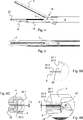
Hinsichtlich der grundsätzlichen Funktionsweise und des mechanischen Aufbaus des Instruments
Die zweite, gemäß
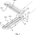
Jede der Instrumentenbranchen
Um einen Kurzschluss zwischen den Elektrodenflächen
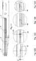
Die
In der
Wie vorstehend ausgeführt wurde, ist der (noppenförmige) Vorsprung
Bei der zweiten Ausführungsform befinden sich anstelle des zwischen den Elektrodenflächen
Aus der
An dieser Stelle sei darauf hingewiesen, dass die vorliegende Erfindung nicht auf die zuvor beschriebene Ausführungsformen beschränkt ist. Diverse Modifikationen innerhalb des Schutzbereichs der beigefügten Ansprüche sind möglich.It should be noted that the present invention is not limited to the embodiments described above. Various modifications are possible within the scope of the appended claims.
So kann beispielsweise in der dritten Ausführungsform anstelle des Vorsprungs
Ferner können bei sämtlichen Ausführungsformen die Vorsprünge bzw. Erhöhungen auf anderen Elektrodenflächen angeordnet werden, solange auf jeder Elektrodenfläche gemäß dem vorliegenden bevorzugten Ausführungsbeispiel nur maximal ein Vorsprung aufgebracht (fixiert) ist.Further, in all embodiments, the protrusions may be disposed on other electrode surfaces as long as only a maximum of one protrusion is applied (fixed) on each electrode surface according to the present preferred embodiment.
Ferner sind Form und Größe der Anstandshalter variierbar, solange alle Abstandshalter so aufeinander abgestimmt sind, dass der Abstand zwischen den Elektrodenflächen an allen Stellen immer gleich ist. So kann der Abstandshalter beispielsweise auch pyramiden-(stumpf)-, zylinder- oder würfelförmig sein. Das Abstandshaltermodul kann schließlich in mehrere nebeneinander angeordnete Einzelmodule mit jeweils nur einer Materialzunge aufgeteilt werden.Furthermore, the shape and size of the chewers can be varied, as long as all spacers are coordinated so that the distance between the electrode surfaces is always the same at all points. For example, the spacer can also be pyramid (dull), cylindrical or cube-shaped. The spacer module can finally be divided into several juxtaposed individual modules, each with only one material tongue.
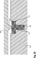
Nachfolgend werden ein Abstandshalter
Wie bereits angeführt wurde, sind die Abstandshalter oder Vorsprünge
Auf einer gegenüberliegenden Elektrode
In diese Vertiefung ist ein Pin / Pad oder Stopfen
Gemäß der
Die
Abschließend sei darauf hingewiesen, dass die Abstandshalter-Aufstandsfläche prinzipiell auch eine andere Form als den gezeigten Stopfen
ZITATE ENTHALTEN IN DER BESCHREIBUNG QUOTES INCLUDE IN THE DESCRIPTION
Diese Liste der vom Anmelder aufgeführten Dokumente wurde automatisiert erzeugt und ist ausschließlich zur besseren Information des Lesers aufgenommen. Die Liste ist nicht Bestandteil der deutschen Patent- bzw. Gebrauchsmusteranmeldung. Das DPMA übernimmt keinerlei Haftung für etwaige Fehler oder Auslassungen.This list of the documents listed by the applicant has been generated automatically and is included solely for the better information of the reader. The list is not part of the German patent or utility model application. The DPMA assumes no liability for any errors or omissions.
Zitierte PatentliteraturCited patent literature
- EP 1747762 A2 [0008] EP 1747762 A2 [0008]
- EP 1656901 B1 [0009] EP 1656901 B1 [0009]
- EP 1952777 A1 [0009] EP 1952777 A1 [0009]
- EP 1372507 A1 [0009] EP 1372507 A1 [0009]
- US 2004/122423 A1 [0009] US 2004/122423 Al [0009]
- WO 2011/097469 A2 [0059, 0061] WO 2011/097469 A2 [0059, 0061]
Claims (11)
Priority Applications (6)
| Application Number | Priority Date | Filing Date | Title |
|---|---|---|---|
| DE102012100040A DE102012100040A1 (en) | 2012-01-04 | 2012-01-04 | Electrosurgical instrument and jaw part for this |
| PCT/EP2012/076945 WO2013102602A2 (en) | 2012-01-04 | 2012-12-27 | Electrosurgical instrument and jaw part therefor |
| US14/370,553 US10092350B2 (en) | 2012-01-04 | 2012-12-27 | Electrosurgical instrument and jaw part therefor |
| ES12813879T ES2729552T3 (en) | 2012-01-04 | 2012-12-27 | Electrosurgical instrument and jaw part for it |
| EP12813879.9A EP2800533B1 (en) | 2012-01-04 | 2012-12-27 | Electrosurgical instrument and jaw part therefor |
| JP2014550685A JP6167111B2 (en) | 2012-01-04 | 2012-12-27 | Electrosurgical instrument and its jaw |
Applications Claiming Priority (1)
| Application Number | Priority Date | Filing Date | Title |
|---|---|---|---|
| DE102012100040A DE102012100040A1 (en) | 2012-01-04 | 2012-01-04 | Electrosurgical instrument and jaw part for this |
Publications (1)
| Publication Number | Publication Date |
|---|---|
| DE102012100040A1 true DE102012100040A1 (en) | 2013-07-04 |
Family
ID=47557117
Family Applications (1)
| Application Number | Title | Priority Date | Filing Date |
|---|---|---|---|
| DE102012100040A Ceased DE102012100040A1 (en) | 2012-01-04 | 2012-01-04 | Electrosurgical instrument and jaw part for this |
Country Status (6)
| Country | Link |
|---|---|
| US (1) | US10092350B2 (en) |
| EP (1) | EP2800533B1 (en) |
| JP (1) | JP6167111B2 (en) |
| DE (1) | DE102012100040A1 (en) |
| ES (1) | ES2729552T3 (en) |
| WO (1) | WO2013102602A2 (en) |
Cited By (6)
| Publication number | Priority date | Publication date | Assignee | Title |
|---|---|---|---|---|
| WO2015197395A1 (en) * | 2014-06-25 | 2015-12-30 | Aesculap Ag | Electrosurgical instrument and jaw part for same |
| US9867655B2 (en) | 2012-02-16 | 2018-01-16 | Aesculap Ag | Electrosurgical instrument having an arcuate electrode section |
| CN108156804A (en) * | 2015-05-21 | 2018-06-12 | 蛇牌股份公司 | Electrosurgery solidifies instrument |
| US10092350B2 (en) | 2012-01-04 | 2018-10-09 | Aesculap Ag | Electrosurgical instrument and jaw part therefor |
| DE102016100588B4 (en) | 2015-01-14 | 2023-03-09 | Gyrus Medical Ltd. | Electrosurgical instrument with electrically conductive stop elements and method for manufacturing a jaw element for an electrosurgical instrument |
| US11633203B2 (en) | 2012-04-17 | 2023-04-25 | A-Base Korlatolt Felelossegu Tarsasag | Manipulator for grasping tissue |
Families Citing this family (147)
| Publication number | Priority date | Publication date | Assignee | Title |
|---|---|---|---|---|
| US10835307B2 (en) | 2001-06-12 | 2020-11-17 | Ethicon Llc | Modular battery powered handheld surgical instrument containing elongated multi-layered shaft |
| US8182501B2 (en) | 2004-02-27 | 2012-05-22 | Ethicon Endo-Surgery, Inc. | Ultrasonic surgical shears and method for sealing a blood vessel using same |
| EP1802245B8 (en) | 2004-10-08 | 2016-09-28 | Ethicon Endo-Surgery, LLC | Ultrasonic surgical instrument |
| US20070191713A1 (en) | 2005-10-14 | 2007-08-16 | Eichmann Stephen E | Ultrasonic device for cutting and coagulating |
| US7621930B2 (en) | 2006-01-20 | 2009-11-24 | Ethicon Endo-Surgery, Inc. | Ultrasound medical instrument having a medical ultrasonic blade |
| US8142461B2 (en) | 2007-03-22 | 2012-03-27 | Ethicon Endo-Surgery, Inc. | Surgical instruments |
| US8057498B2 (en) | 2007-11-30 | 2011-11-15 | Ethicon Endo-Surgery, Inc. | Ultrasonic surgical instrument blades |
| US8911460B2 (en) | 2007-03-22 | 2014-12-16 | Ethicon Endo-Surgery, Inc. | Ultrasonic surgical instruments |
| US8523889B2 (en) | 2007-07-27 | 2013-09-03 | Ethicon Endo-Surgery, Inc. | Ultrasonic end effectors with increased active length |
| US8808319B2 (en) | 2007-07-27 | 2014-08-19 | Ethicon Endo-Surgery, Inc. | Surgical instruments |
| US8430898B2 (en) | 2007-07-31 | 2013-04-30 | Ethicon Endo-Surgery, Inc. | Ultrasonic surgical instruments |
| US8512365B2 (en) | 2007-07-31 | 2013-08-20 | Ethicon Endo-Surgery, Inc. | Surgical instruments |
| US9044261B2 (en) | 2007-07-31 | 2015-06-02 | Ethicon Endo-Surgery, Inc. | Temperature controlled ultrasonic surgical instruments |
| AU2008308606B2 (en) | 2007-10-05 | 2014-12-18 | Ethicon Endo-Surgery, Inc. | Ergonomic surgical instruments |
| US10010339B2 (en) | 2007-11-30 | 2018-07-03 | Ethicon Llc | Ultrasonic surgical blades |
| US9089360B2 (en) | 2008-08-06 | 2015-07-28 | Ethicon Endo-Surgery, Inc. | Devices and techniques for cutting and coagulating tissue |
| US9700339B2 (en) | 2009-05-20 | 2017-07-11 | Ethicon Endo-Surgery, Inc. | Coupling arrangements and methods for attaching tools to ultrasonic surgical instruments |
| US8663220B2 (en) | 2009-07-15 | 2014-03-04 | Ethicon Endo-Surgery, Inc. | Ultrasonic surgical instruments |
| US9039695B2 (en) | 2009-10-09 | 2015-05-26 | Ethicon Endo-Surgery, Inc. | Surgical generator for ultrasonic and electrosurgical devices |
| US10441345B2 (en) | 2009-10-09 | 2019-10-15 | Ethicon Llc | Surgical generator for ultrasonic and electrosurgical devices |
| US10172669B2 (en) | 2009-10-09 | 2019-01-08 | Ethicon Llc | Surgical instrument comprising an energy trigger lockout |
| US11090104B2 (en) | 2009-10-09 | 2021-08-17 | Cilag Gmbh International | Surgical generator for ultrasonic and electrosurgical devices |
| US8486096B2 (en) | 2010-02-11 | 2013-07-16 | Ethicon Endo-Surgery, Inc. | Dual purpose surgical instrument for cutting and coagulating tissue |
| US8951272B2 (en) | 2010-02-11 | 2015-02-10 | Ethicon Endo-Surgery, Inc. | Seal arrangements for ultrasonically powered surgical instruments |
| US8469981B2 (en) | 2010-02-11 | 2013-06-25 | Ethicon Endo-Surgery, Inc. | Rotatable cutting implement arrangements for ultrasonic surgical instruments |
| US8834518B2 (en) | 2010-04-12 | 2014-09-16 | Ethicon Endo-Surgery, Inc. | Electrosurgical cutting and sealing instruments with cam-actuated jaws |
| GB2480498A (en) | 2010-05-21 | 2011-11-23 | Ethicon Endo Surgery Inc | Medical device comprising RF circuitry |
| US8795327B2 (en) | 2010-07-22 | 2014-08-05 | Ethicon Endo-Surgery, Inc. | Electrosurgical instrument with separate closure and cutting members |
| US9192431B2 (en) | 2010-07-23 | 2015-11-24 | Ethicon Endo-Surgery, Inc. | Electrosurgical cutting and sealing instrument |
| US9259265B2 (en) | 2011-07-22 | 2016-02-16 | Ethicon Endo-Surgery, Llc | Surgical instruments for tensioning tissue |
| US9044243B2 (en) | 2011-08-30 | 2015-06-02 | Ethcon Endo-Surgery, Inc. | Surgical cutting and fastening device with descendible second trigger arrangement |
| JP6234932B2 (en) | 2011-10-24 | 2017-11-22 | エシコン・エンド−サージェリィ・インコーポレイテッドEthicon Endo−Surgery,Inc. | Medical instruments |
| WO2013119545A1 (en) | 2012-02-10 | 2013-08-15 | Ethicon-Endo Surgery, Inc. | Robotically controlled surgical instrument |
| US9439668B2 (en) | 2012-04-09 | 2016-09-13 | Ethicon Endo-Surgery, Llc | Switch arrangements for ultrasonic surgical instruments |
| US20140005705A1 (en) | 2012-06-29 | 2014-01-02 | Ethicon Endo-Surgery, Inc. | Surgical instruments with articulating shafts |
| US9351754B2 (en) | 2012-06-29 | 2016-05-31 | Ethicon Endo-Surgery, Llc | Ultrasonic surgical instruments with distally positioned jaw assemblies |
| US9226767B2 (en) | 2012-06-29 | 2016-01-05 | Ethicon Endo-Surgery, Inc. | Closed feedback control for electrosurgical device |
| US9326788B2 (en) | 2012-06-29 | 2016-05-03 | Ethicon Endo-Surgery, Llc | Lockout mechanism for use with robotic electrosurgical device |
| US20140005702A1 (en) | 2012-06-29 | 2014-01-02 | Ethicon Endo-Surgery, Inc. | Ultrasonic surgical instruments with distally positioned transducers |
| US9198714B2 (en) | 2012-06-29 | 2015-12-01 | Ethicon Endo-Surgery, Inc. | Haptic feedback devices for surgical robot |
| US9408622B2 (en) | 2012-06-29 | 2016-08-09 | Ethicon Endo-Surgery, Llc | Surgical instruments with articulating shafts |
| US9393037B2 (en) | 2012-06-29 | 2016-07-19 | Ethicon Endo-Surgery, Llc | Surgical instruments with articulating shafts |
| US9820768B2 (en) | 2012-06-29 | 2017-11-21 | Ethicon Llc | Ultrasonic surgical instruments with control mechanisms |
| WO2014052181A1 (en) | 2012-09-28 | 2014-04-03 | Ethicon Endo-Surgery, Inc. | Multi-function bi-polar forceps |
| US9095367B2 (en) | 2012-10-22 | 2015-08-04 | Ethicon Endo-Surgery, Inc. | Flexible harmonic waveguides/blades for surgical instruments |
| US20140135804A1 (en) | 2012-11-15 | 2014-05-15 | Ethicon Endo-Surgery, Inc. | Ultrasonic and electrosurgical devices |
| US10226273B2 (en) | 2013-03-14 | 2019-03-12 | Ethicon Llc | Mechanical fasteners for use with surgical energy devices |
| US9814514B2 (en) | 2013-09-13 | 2017-11-14 | Ethicon Llc | Electrosurgical (RF) medical instruments for cutting and coagulating tissue |
| US9265926B2 (en) | 2013-11-08 | 2016-02-23 | Ethicon Endo-Surgery, Llc | Electrosurgical devices |
| GB2521228A (en) | 2013-12-16 | 2015-06-17 | Ethicon Endo Surgery Inc | Medical device |
| GB2521229A (en) | 2013-12-16 | 2015-06-17 | Ethicon Endo Surgery Inc | Medical device |
| US9795436B2 (en) | 2014-01-07 | 2017-10-24 | Ethicon Llc | Harvesting energy from a surgical generator |
| US9554854B2 (en) | 2014-03-18 | 2017-01-31 | Ethicon Endo-Surgery, Llc | Detecting short circuits in electrosurgical medical devices |
| US10463421B2 (en) | 2014-03-27 | 2019-11-05 | Ethicon Llc | Two stage trigger, clamp and cut bipolar vessel sealer |
| US10092310B2 (en) | 2014-03-27 | 2018-10-09 | Ethicon Llc | Electrosurgical devices |
| US10524852B1 (en) | 2014-03-28 | 2020-01-07 | Ethicon Llc | Distal sealing end effector with spacers |
| US9737355B2 (en) | 2014-03-31 | 2017-08-22 | Ethicon Llc | Controlling impedance rise in electrosurgical medical devices |
| US9980769B2 (en) | 2014-04-08 | 2018-05-29 | Ethicon Llc | Methods and devices for controlling motorized surgical devices |
| US9913680B2 (en) | 2014-04-15 | 2018-03-13 | Ethicon Llc | Software algorithms for electrosurgical instruments |
| US9757186B2 (en) | 2014-04-17 | 2017-09-12 | Ethicon Llc | Device status feedback for bipolar tissue spacer |
| US10285724B2 (en) | 2014-07-31 | 2019-05-14 | Ethicon Llc | Actuation mechanisms and load adjustment assemblies for surgical instruments |
| US10194976B2 (en) | 2014-08-25 | 2019-02-05 | Ethicon Llc | Lockout disabling mechanism |
| US9877776B2 (en) | 2014-08-25 | 2018-01-30 | Ethicon Llc | Simultaneous I-beam and spring driven cam jaw closure mechanism |
| US10194972B2 (en) | 2014-08-26 | 2019-02-05 | Ethicon Llc | Managing tissue treatment |
| US10639092B2 (en) | 2014-12-08 | 2020-05-05 | Ethicon Llc | Electrode configurations for surgical instruments |
| US9848937B2 (en) | 2014-12-22 | 2017-12-26 | Ethicon Llc | End effector with detectable configurations |
| US10159524B2 (en) | 2014-12-22 | 2018-12-25 | Ethicon Llc | High power battery powered RF amplifier topology |
| US10111699B2 (en) | 2014-12-22 | 2018-10-30 | Ethicon Llc | RF tissue sealer, shear grip, trigger lock mechanism and energy activation |
| US10092348B2 (en) | 2014-12-22 | 2018-10-09 | Ethicon Llc | RF tissue sealer, shear grip, trigger lock mechanism and energy activation |
| GB2535627B (en) * | 2015-01-14 | 2017-06-28 | Gyrus Medical Ltd | Electrosurgical system |
| US10245095B2 (en) | 2015-02-06 | 2019-04-02 | Ethicon Llc | Electrosurgical instrument with rotation and articulation mechanisms |
| US10342602B2 (en) | 2015-03-17 | 2019-07-09 | Ethicon Llc | Managing tissue treatment |
| US10321950B2 (en) | 2015-03-17 | 2019-06-18 | Ethicon Llc | Managing tissue treatment |
| US10595929B2 (en) | 2015-03-24 | 2020-03-24 | Ethicon Llc | Surgical instruments with firing system overload protection mechanisms |
| US10314638B2 (en) | 2015-04-07 | 2019-06-11 | Ethicon Llc | Articulating radio frequency (RF) tissue seal with articulating state sensing |
| US10117702B2 (en) | 2015-04-10 | 2018-11-06 | Ethicon Llc | Surgical generator systems and related methods |
| US10130410B2 (en) | 2015-04-17 | 2018-11-20 | Ethicon Llc | Electrosurgical instrument including a cutting member decouplable from a cutting member trigger |
| US9872725B2 (en) | 2015-04-29 | 2018-01-23 | Ethicon Llc | RF tissue sealer with mode selection |
| US11020140B2 (en) | 2015-06-17 | 2021-06-01 | Cilag Gmbh International | Ultrasonic surgical blade for use with ultrasonic surgical instruments |
| US11141213B2 (en) | 2015-06-30 | 2021-10-12 | Cilag Gmbh International | Surgical instrument with user adaptable techniques |
| US11129669B2 (en) | 2015-06-30 | 2021-09-28 | Cilag Gmbh International | Surgical system with user adaptable techniques based on tissue type |
| US10357303B2 (en) | 2015-06-30 | 2019-07-23 | Ethicon Llc | Translatable outer tube for sealing using shielded lap chole dissector |
| US10034704B2 (en) | 2015-06-30 | 2018-07-31 | Ethicon Llc | Surgical instrument with user adaptable algorithms |
| US10898256B2 (en) | 2015-06-30 | 2021-01-26 | Ethicon Llc | Surgical system with user adaptable techniques based on tissue impedance |
| US11051873B2 (en) | 2015-06-30 | 2021-07-06 | Cilag Gmbh International | Surgical system with user adaptable techniques employing multiple energy modalities based on tissue parameters |
| US10154852B2 (en) | 2015-07-01 | 2018-12-18 | Ethicon Llc | Ultrasonic surgical blade with improved cutting and coagulation features |
| US10194973B2 (en) | 2015-09-30 | 2019-02-05 | Ethicon Llc | Generator for digitally generating electrical signal waveforms for electrosurgical and ultrasonic surgical instruments |
| US10959771B2 (en) | 2015-10-16 | 2021-03-30 | Ethicon Llc | Suction and irrigation sealing grasper |
| US10595930B2 (en) | 2015-10-16 | 2020-03-24 | Ethicon Llc | Electrode wiping surgical device |
| US10959806B2 (en) | 2015-12-30 | 2021-03-30 | Ethicon Llc | Energized medical device with reusable handle |
| US10179022B2 (en) | 2015-12-30 | 2019-01-15 | Ethicon Llc | Jaw position impedance limiter for electrosurgical instrument |
| US10575892B2 (en) | 2015-12-31 | 2020-03-03 | Ethicon Llc | Adapter for electrical surgical instruments |
| US11229471B2 (en) | 2016-01-15 | 2022-01-25 | Cilag Gmbh International | Modular battery powered handheld surgical instrument with selective application of energy based on tissue characterization |
| US11129670B2 (en) | 2016-01-15 | 2021-09-28 | Cilag Gmbh International | Modular battery powered handheld surgical instrument with selective application of energy based on button displacement, intensity, or local tissue characterization |
| US11051840B2 (en) | 2016-01-15 | 2021-07-06 | Ethicon Llc | Modular battery powered handheld surgical instrument with reusable asymmetric handle housing |
| US10716615B2 (en) | 2016-01-15 | 2020-07-21 | Ethicon Llc | Modular battery powered handheld surgical instrument with curved end effectors having asymmetric engagement between jaw and blade |
| US10555769B2 (en) | 2016-02-22 | 2020-02-11 | Ethicon Llc | Flexible circuits for electrosurgical instrument |
| US10856934B2 (en) | 2016-04-29 | 2020-12-08 | Ethicon Llc | Electrosurgical instrument with electrically conductive gap setting and tissue engaging members |
| US10485607B2 (en) | 2016-04-29 | 2019-11-26 | Ethicon Llc | Jaw structure with distal closure for electrosurgical instruments |
| US10702329B2 (en) * | 2016-04-29 | 2020-07-07 | Ethicon Llc | Jaw structure with distal post for electrosurgical instruments |
| US10646269B2 (en) | 2016-04-29 | 2020-05-12 | Ethicon Llc | Non-linear jaw gap for electrosurgical instruments |
| US10987156B2 (en) | 2016-04-29 | 2021-04-27 | Ethicon Llc | Electrosurgical instrument with electrically conductive gap setting member and electrically insulative tissue engaging members |
| US10456193B2 (en) | 2016-05-03 | 2019-10-29 | Ethicon Llc | Medical device with a bilateral jaw configuration for nerve stimulation |
| US10245064B2 (en) | 2016-07-12 | 2019-04-02 | Ethicon Llc | Ultrasonic surgical instrument with piezoelectric central lumen transducer |
| US10893883B2 (en) | 2016-07-13 | 2021-01-19 | Ethicon Llc | Ultrasonic assembly for use with ultrasonic surgical instruments |
| US10842522B2 (en) | 2016-07-15 | 2020-11-24 | Ethicon Llc | Ultrasonic surgical instruments having offset blades |
| US10376305B2 (en) | 2016-08-05 | 2019-08-13 | Ethicon Llc | Methods and systems for advanced harmonic energy |
| US10285723B2 (en) | 2016-08-09 | 2019-05-14 | Ethicon Llc | Ultrasonic surgical blade with improved heel portion |
| USD847990S1 (en) | 2016-08-16 | 2019-05-07 | Ethicon Llc | Surgical instrument |
| US10828056B2 (en) | 2016-08-25 | 2020-11-10 | Ethicon Llc | Ultrasonic transducer to waveguide acoustic coupling, connections, and configurations |
| US10952759B2 (en) | 2016-08-25 | 2021-03-23 | Ethicon Llc | Tissue loading of a surgical instrument |
| US10751117B2 (en) | 2016-09-23 | 2020-08-25 | Ethicon Llc | Electrosurgical instrument with fluid diverter |
| US10603064B2 (en) | 2016-11-28 | 2020-03-31 | Ethicon Llc | Ultrasonic transducer |
| US11266430B2 (en) | 2016-11-29 | 2022-03-08 | Cilag Gmbh International | End effector control and calibration |
| US11033325B2 (en) | 2017-02-16 | 2021-06-15 | Cilag Gmbh International | Electrosurgical instrument with telescoping suction port and debris cleaner |
| US10799284B2 (en) | 2017-03-15 | 2020-10-13 | Ethicon Llc | Electrosurgical instrument with textured jaws |
| US11497546B2 (en) | 2017-03-31 | 2022-11-15 | Cilag Gmbh International | Area ratios of patterned coatings on RF electrodes to reduce sticking |
| US10603117B2 (en) | 2017-06-28 | 2020-03-31 | Ethicon Llc | Articulation state detection mechanisms |
| US10820920B2 (en) | 2017-07-05 | 2020-11-03 | Ethicon Llc | Reusable ultrasonic medical devices and methods of their use |
| US11490951B2 (en) | 2017-09-29 | 2022-11-08 | Cilag Gmbh International | Saline contact with electrodes |
| US11484358B2 (en) | 2017-09-29 | 2022-11-01 | Cilag Gmbh International | Flexible electrosurgical instrument |
| US11033323B2 (en) | 2017-09-29 | 2021-06-15 | Cilag Gmbh International | Systems and methods for managing fluid and suction in electrosurgical systems |
| GB2567654B (en) * | 2017-10-18 | 2022-10-05 | Gyrus Medical Ltd | Electrosurgical instrument |
| US11813017B2 (en) | 2019-03-11 | 2023-11-14 | Microline Surgical, Inc. | Reusable minimally invasive surgical instrument |
| JP1660090S (en) * | 2019-10-04 | 2020-05-25 | ||
| JP1660086S (en) * | 2019-10-04 | 2020-05-25 | ||
| JP1660087S (en) * | 2019-10-04 | 2020-05-25 | ||
| JP1660089S (en) * | 2019-10-04 | 2020-05-25 | ||
| US20210196349A1 (en) | 2019-12-30 | 2021-07-01 | Ethicon Llc | Electrosurgical instrument with flexible wiring assemblies |
| US11779329B2 (en) | 2019-12-30 | 2023-10-10 | Cilag Gmbh International | Surgical instrument comprising a flex circuit including a sensor system |
| US11786294B2 (en) | 2019-12-30 | 2023-10-17 | Cilag Gmbh International | Control program for modular combination energy device |
| US11911063B2 (en) | 2019-12-30 | 2024-02-27 | Cilag Gmbh International | Techniques for detecting ultrasonic blade to electrode contact and reducing power to ultrasonic blade |
| US11950797B2 (en) | 2019-12-30 | 2024-04-09 | Cilag Gmbh International | Deflectable electrode with higher distal bias relative to proximal bias |
| US11937866B2 (en) | 2019-12-30 | 2024-03-26 | Cilag Gmbh International | Method for an electrosurgical procedure |
| US11812957B2 (en) | 2019-12-30 | 2023-11-14 | Cilag Gmbh International | Surgical instrument comprising a signal interference resolution system |
| US11707318B2 (en) | 2019-12-30 | 2023-07-25 | Cilag Gmbh International | Surgical instrument with jaw alignment features |
| US11779387B2 (en) | 2019-12-30 | 2023-10-10 | Cilag Gmbh International | Clamp arm jaw to minimize tissue sticking and improve tissue control |
| US11937863B2 (en) | 2019-12-30 | 2024-03-26 | Cilag Gmbh International | Deflectable electrode with variable compression bias along the length of the deflectable electrode |
| US11944366B2 (en) | 2019-12-30 | 2024-04-02 | Cilag Gmbh International | Asymmetric segmented ultrasonic support pad for cooperative engagement with a movable RF electrode |
| US11786291B2 (en) | 2019-12-30 | 2023-10-17 | Cilag Gmbh International | Deflectable support of RF energy electrode with respect to opposing ultrasonic blade |
| US11696776B2 (en) | 2019-12-30 | 2023-07-11 | Cilag Gmbh International | Articulatable surgical instrument |
| US20210196362A1 (en) | 2019-12-30 | 2021-07-01 | Ethicon Llc | Electrosurgical end effectors with thermally insulative and thermally conductive portions |
| US11660089B2 (en) | 2019-12-30 | 2023-05-30 | Cilag Gmbh International | Surgical instrument comprising a sensing system |
| US11452525B2 (en) | 2019-12-30 | 2022-09-27 | Cilag Gmbh International | Surgical instrument comprising an adjustment system |
| JP1702878S (en) * | 2021-04-09 | 2021-12-20 | ||
| US11957342B2 (en) | 2021-11-01 | 2024-04-16 | Cilag Gmbh International | Devices, systems, and methods for detecting tissue and foreign objects during a surgical operation |
| DE102022115164A1 (en) | 2022-06-16 | 2023-12-21 | Olympus Winter & Ibe Gmbh | Surgical tool and electrosurgical hand instrument and method for recognizing a surgical tool |
Citations (7)
| Publication number | Priority date | Publication date | Assignee | Title |
|---|---|---|---|---|
| EP1372507A1 (en) | 2001-04-06 | 2004-01-02 | Sherwood Services AG | Vessel sealer and divider with non-conductive stop members |
| DE102004031141A1 (en) * | 2004-06-28 | 2006-01-26 | Erbe Elektromedizin Gmbh | Electrosurgical instrument |
| DE202006016837U1 (en) * | 2005-11-02 | 2007-01-11 | Olympus Winter & Ibe Gmbh | Endoscopic bipolar tongs used in laparoscopic surgery comprises spacer pieces arranged outside of the gripping surfaces |
| EP1747762A2 (en) | 2005-07-26 | 2007-01-31 | Aesculap AG & Co. KG | Coagulation forceps for surgical applications |
| EP1952777A1 (en) | 2001-04-06 | 2008-08-06 | Codivien AG | Vessel sealer and divider |
| DE102008008309A1 (en) * | 2008-02-07 | 2009-08-20 | Olympus Winter & Ibe Gmbh | Endoscopic forceps for grasping blood vessel have electric conductive spacer attached to surface and contacting another surface, while approaching surfaces, where one of surfaces has insulation coating in place contacted by spacer |
| WO2011097469A2 (en) | 2010-02-04 | 2011-08-11 | Aragon Surgical, Inc. | Laparoscopic radiofrequency surgical device |
Family Cites Families (46)
| Publication number | Priority date | Publication date | Assignee | Title |
|---|---|---|---|---|
| DE2324658B2 (en) | 1973-05-16 | 1977-06-30 | Richard Wolf Gmbh, 7134 Knittlingen | PROBE FOR COAGULATING BODY TISSUE |
| FR2505170B1 (en) | 1981-05-06 | 1985-08-02 | Metallisations Traitements Opt | BIOPSY TONGS |
| US5222973A (en) | 1992-03-09 | 1993-06-29 | Sharpe Endosurgical Corporation | Endoscopic grasping tool surgical instrument |
| US5258006A (en) | 1992-08-21 | 1993-11-02 | Everest Medical Corporation | Bipolar electrosurgical forceps |
| US5638827A (en) | 1994-02-01 | 1997-06-17 | Symbiosis Corporation | Super-elastic flexible jaws assembly for an endoscopic multiple sample bioptome |
| US5891142A (en) | 1996-12-06 | 1999-04-06 | Eggers & Associates, Inc. | Electrosurgical forceps |
| EP1027000A4 (en) | 1997-10-09 | 2001-09-12 | Camran Nezhat | Methods and systems for organ resection |
| US7582087B2 (en) | 1998-10-23 | 2009-09-01 | Covidien Ag | Vessel sealing instrument |
| US20040249374A1 (en) | 1998-10-23 | 2004-12-09 | Tetzlaff Philip M. | Vessel sealing instrument |
| WO2000024330A1 (en) | 1998-10-23 | 2000-05-04 | Sherwood Services Ag | Open vessel sealing forceps with disposable electrodes |
| EP2072017B1 (en) | 1998-10-23 | 2018-04-18 | Covidien AG | Endoscopic bipolar electrosurgical forceps |
| JP4699679B2 (en) | 2001-04-06 | 2011-06-15 | コヴィディエン・アクチェンゲゼルシャフト | Blood vessel sealing device |
| US6802843B2 (en) | 2001-09-13 | 2004-10-12 | Csaba Truckai | Electrosurgical working end with resistive gradient electrodes |
| US6770072B1 (en) | 2001-10-22 | 2004-08-03 | Surgrx, Inc. | Electrosurgical jaw structure for controlled energy delivery |
| JP4420593B2 (en) | 2002-07-29 | 2010-02-24 | Hoya株式会社 | Bipolar high-frequency treatment instrument for endoscope |
| US7270664B2 (en) | 2002-10-04 | 2007-09-18 | Sherwood Services Ag | Vessel sealing instrument with electrical cutting mechanism |
| US7753909B2 (en) | 2003-05-01 | 2010-07-13 | Covidien Ag | Electrosurgical instrument which reduces thermal damage to adjacent tissue |
| US8128624B2 (en) | 2003-05-01 | 2012-03-06 | Covidien Ag | Electrosurgical instrument that directs energy delivery and protects adjacent tissue |
| JP5137230B2 (en) | 2003-05-15 | 2013-02-06 | コヴィディエン・アクチェンゲゼルシャフト | Tissue sealer with non-conductive variable stop member and method for sealing tissue |
| JP4253540B2 (en) | 2003-07-24 | 2009-04-15 | オリンパス株式会社 | Medical instrument |
| US7252667B2 (en) | 2003-11-19 | 2007-08-07 | Sherwood Services Ag | Open vessel sealing instrument with cutting mechanism and distal lockout |
| US20050192611A1 (en) | 2004-02-27 | 2005-09-01 | Houser Kevin L. | Ultrasonic surgical instrument, shears and tissue pad, method for sealing a blood vessel and method for transecting patient tissue |
| US7645285B2 (en) | 2004-05-26 | 2010-01-12 | Idx Medical, Ltd | Apparatus and methods for occluding a hollow anatomical structure |
| DE202004009427U1 (en) | 2004-06-16 | 2004-08-12 | Richard Wolf Gmbh | Surgical gripping DE4vice to be used for blocking of uterine tubes, comprising three coagulation sections |
| DE102006042985A1 (en) | 2005-10-04 | 2007-04-19 | Erbe Elektromedizin Gmbh | Electrosurgical instrument for coagulating tissue, has deformable unit arranged on branch or gripping device such that area of gripping device can be moved to actuate switching device when branches are closed and minimum distance is reached |
| US7717914B2 (en) * | 2006-07-11 | 2010-05-18 | Olympus Medical Systems Corporation | Treatment device |
| JP2008058123A (en) | 2006-08-31 | 2008-03-13 | Hitachi High-Technologies Corp | Autoanalyzer |
| WO2008045350A2 (en) | 2006-10-06 | 2008-04-17 | Tyco Healthcare Group Lp | Endoscopic vessel sealer and divider having a flexible articulating shaft |
| US8475453B2 (en) | 2006-10-06 | 2013-07-02 | Covidien Lp | Endoscopic vessel sealer and divider having a flexible articulating shaft |
| DE102007005359B4 (en) | 2007-02-02 | 2011-04-28 | Webasto Ag | Vehicle with a fuel cell system, a fuel cell system and a safety device comprehensive arrangement and method for operating the fuel cell system |
| CN201082191Y (en) | 2007-09-17 | 2008-07-09 | 梅郎 | Combination type electrode forceps |
| DE102008018614B4 (en) | 2008-04-11 | 2012-06-28 | Hebumedical Gmbh | Clamp for electrosurgical applications |
| JP5380705B2 (en) | 2008-05-15 | 2014-01-08 | 株式会社リバーセイコー | Endoscopic high frequency hemostatic forceps |
| US8469956B2 (en) | 2008-07-21 | 2013-06-25 | Covidien Lp | Variable resistor jaw |
| US8795274B2 (en) | 2008-08-28 | 2014-08-05 | Covidien Lp | Tissue fusion jaw angle improvement |
| US7896214B2 (en) | 2008-09-23 | 2011-03-01 | Tyco Healthcare Group Lp | Tissue stop for surgical instrument |
| US8277446B2 (en) | 2009-04-24 | 2012-10-02 | Tyco Healthcare Group Lp | Electrosurgical tissue sealer and cutter |
| DE102009037614A1 (en) | 2009-08-14 | 2011-02-24 | Erbe Elektromedizin Gmbh | Electrosurgical instrument |
| DE102009037613A1 (en) | 2009-08-14 | 2011-02-24 | Erbe Elektromedizin Gmbh | Electrosurgical instrument |
| US8512371B2 (en) | 2009-10-06 | 2013-08-20 | Covidien Lp | Jaw, blade and gap manufacturing for surgical instruments with small jaws |
| US8979890B2 (en) | 2010-10-01 | 2015-03-17 | Ethicon Endo-Surgery, Inc. | Surgical instrument with jaw member |
| US8568408B2 (en) | 2011-04-21 | 2013-10-29 | Covidien Lp | Surgical forceps |
| DE102012100040A1 (en) | 2012-01-04 | 2013-07-04 | Aesculap Ag | Electrosurgical instrument and jaw part for this |
| DE202012100017U1 (en) * | 2012-01-04 | 2012-03-22 | Aesculap Ag | Electrosurgical instrument and jaw part for this |
| US9265514B2 (en) | 2012-04-17 | 2016-02-23 | Miteas Ltd. | Manipulator for grasping tissue |
| DE102014108914A1 (en) | 2014-06-25 | 2015-12-31 | Aesculap Ag | Electrosurgical instrument and jaw part for this |
-
2012
- 2012-01-04 DE DE102012100040A patent/DE102012100040A1/en not_active Ceased
- 2012-12-27 WO PCT/EP2012/076945 patent/WO2013102602A2/en active Application Filing
- 2012-12-27 JP JP2014550685A patent/JP6167111B2/en active Active
- 2012-12-27 US US14/370,553 patent/US10092350B2/en active Active
- 2012-12-27 EP EP12813879.9A patent/EP2800533B1/en active Active
- 2012-12-27 ES ES12813879T patent/ES2729552T3/en active Active
Patent Citations (9)
| Publication number | Priority date | Publication date | Assignee | Title |
|---|---|---|---|---|
| EP1372507A1 (en) | 2001-04-06 | 2004-01-02 | Sherwood Services AG | Vessel sealer and divider with non-conductive stop members |
| US20040122423A1 (en) | 2001-04-06 | 2004-06-24 | Dycus Sean T. | Vessel sealer and divider with non-conductive stop members |
| EP1952777A1 (en) | 2001-04-06 | 2008-08-06 | Codivien AG | Vessel sealer and divider |
| EP1656901B1 (en) | 2001-04-06 | 2009-09-02 | Covidien AG | Vessel sealer and divider with non-conductive stop members |
| DE102004031141A1 (en) * | 2004-06-28 | 2006-01-26 | Erbe Elektromedizin Gmbh | Electrosurgical instrument |
| EP1747762A2 (en) | 2005-07-26 | 2007-01-31 | Aesculap AG & Co. KG | Coagulation forceps for surgical applications |
| DE202006016837U1 (en) * | 2005-11-02 | 2007-01-11 | Olympus Winter & Ibe Gmbh | Endoscopic bipolar tongs used in laparoscopic surgery comprises spacer pieces arranged outside of the gripping surfaces |
| DE102008008309A1 (en) * | 2008-02-07 | 2009-08-20 | Olympus Winter & Ibe Gmbh | Endoscopic forceps for grasping blood vessel have electric conductive spacer attached to surface and contacting another surface, while approaching surfaces, where one of surfaces has insulation coating in place contacted by spacer |
| WO2011097469A2 (en) | 2010-02-04 | 2011-08-11 | Aragon Surgical, Inc. | Laparoscopic radiofrequency surgical device |
Cited By (10)
| Publication number | Priority date | Publication date | Assignee | Title |
|---|---|---|---|---|
| US10092350B2 (en) | 2012-01-04 | 2018-10-09 | Aesculap Ag | Electrosurgical instrument and jaw part therefor |
| US9867655B2 (en) | 2012-02-16 | 2018-01-16 | Aesculap Ag | Electrosurgical instrument having an arcuate electrode section |
| US10575896B2 (en) | 2012-02-16 | 2020-03-03 | Aesculap Ag | Electrosurgical instrument having an arcuate electrode section |
| US11633203B2 (en) | 2012-04-17 | 2023-04-25 | A-Base Korlatolt Felelossegu Tarsasag | Manipulator for grasping tissue |
| WO2015197395A1 (en) * | 2014-06-25 | 2015-12-30 | Aesculap Ag | Electrosurgical instrument and jaw part for same |
| CN106456248A (en) * | 2014-06-25 | 2017-02-22 | 蛇牌股份公司 | Electrosurgical instrument and jaw part for same |
| US20170135751A1 (en) * | 2014-06-25 | 2017-05-18 | Aesculap Ag | Electrosurgical instrument and jaw part for same |
| JP2017518825A (en) * | 2014-06-25 | 2017-07-13 | アエスキュラップ アーゲー | Electrosurgical instrument and jaw part for electrosurgical instrument |
| DE102016100588B4 (en) | 2015-01-14 | 2023-03-09 | Gyrus Medical Ltd. | Electrosurgical instrument with electrically conductive stop elements and method for manufacturing a jaw element for an electrosurgical instrument |
| CN108156804A (en) * | 2015-05-21 | 2018-06-12 | 蛇牌股份公司 | Electrosurgery solidifies instrument |
Also Published As
| Publication number | Publication date |
|---|---|
| JP2015504734A (en) | 2015-02-16 |
| JP6167111B2 (en) | 2017-07-19 |
| US20140371743A1 (en) | 2014-12-18 |
| EP2800533B1 (en) | 2019-04-10 |
| WO2013102602A3 (en) | 2013-10-24 |
| WO2013102602A2 (en) | 2013-07-11 |
| EP2800533A2 (en) | 2014-11-12 |
| US10092350B2 (en) | 2018-10-09 |
| ES2729552T3 (en) | 2019-11-04 |
Similar Documents
| Publication | Publication Date | Title |
|---|---|---|
| EP2800533B1 (en) | Electrosurgical instrument and jaw part therefor | |
| DE102014108914A1 (en) | Electrosurgical instrument and jaw part for this | |
| DE102012106067A1 (en) | Electrosurgical instrument and jaw part for this | |
| DE60312873T2 (en) | ELECTRO-SURGICAL INSTRUMENT FOR CLOSING VESSELS | |
| EP2335608B1 (en) | Surgical system for connecting bodily tissues | |
| DE69823862T2 (en) | BIOPOLAR ELECTRO-SURGICAL LAPAROSCOPE INSTRUMENT | |
| DE69823437T2 (en) | Electrosurgical cutting instrument | |
| DE102008019380B4 (en) | Bipolar clamp for HF surgery | |
| DE19700605B4 (en) | Instrument, in particular for endoscopic surgery | |
| DE602005004637T2 (en) | Pliers with spring-loaded gripping element | |
| EP2512358B1 (en) | Surgical system and control method for a surgical instrument for connecting bodily tissues | |
| DE60017272T2 (en) | ELECTRO-SURGICAL COAGULATION CUTTING INSTRUMENT | |
| DE102007053359B3 (en) | Surgical instrument | |
| DE202012100017U1 (en) | Electrosurgical instrument and jaw part for this | |
| EP2911595B1 (en) | Anastomosis instrument with pivotable anvil | |
| EP2512349B1 (en) | Surgical system for bonding bodily tissue and for cutting off protruding tissue | |
| DE102012103503A1 (en) | Medical TFT instrument with pivotable electrode bearing | |
| EP3049008B1 (en) | Hf surgical instrument | |
| EP2814414B1 (en) | Electrosurgical instrument with an arcuate electrode part | |
| EP2653123A1 (en) | Tool for a medical instrument | |
| DE102009002768A1 (en) | Material layer and electrosurgical system for electrosurgical tissue fusion | |
| DE202012100833U1 (en) | Electrosurgical instrument and jaw part for this | |
| DE202007015547U1 (en) | Surgical instrument | |
| DE102010044084A1 (en) | Bipolar coagulation forceps for seizing, dissecting and bipolar coagulating of tissue in neurosurgery, have manually operable electric switch arranged in region near gripping portion for activation of coagulation current circuit | |
| DE102009049399A1 (en) | Electrosurgical instrument |
Legal Events
| Date | Code | Title | Description |
|---|---|---|---|
| R163 | Identified publications notified | ||
| R082 | Change of representative |
Representative=s name: WINTER, BRANDL, FUERNISS, HUEBNER, ROESS, KAIS, DE |
|
| R012 | Request for examination validly filed | ||
| R002 | Refusal decision in examination/registration proceedings | ||
| R003 | Refusal decision now final |