DE102013200085A1 - Highly efficient phosphorescent materials - Google Patents
Highly efficient phosphorescent materials Download PDFInfo
- Publication number
- DE102013200085A1 DE102013200085A1 DE102013200085A DE102013200085A DE102013200085A1 DE 102013200085 A1 DE102013200085 A1 DE 102013200085A1 DE 102013200085 A DE102013200085 A DE 102013200085A DE 102013200085 A DE102013200085 A DE 102013200085A DE 102013200085 A1 DE102013200085 A1 DE 102013200085A1
- Authority
- DE
- Germany
- Prior art keywords
- compound
- group
- formula
- alkyl
- combinations
- Prior art date
- Legal status (The legal status is an assumption and is not a legal conclusion. Google has not performed a legal analysis and makes no representation as to the accuracy of the status listed.)
- Granted
Links
Images


Classifications
-
- H—ELECTRICITY
- H10—SEMICONDUCTOR DEVICES; ELECTRIC SOLID-STATE DEVICES NOT OTHERWISE PROVIDED FOR
- H10K—ORGANIC ELECTRIC SOLID-STATE DEVICES
- H10K85/00—Organic materials used in the body or electrodes of devices covered by this subclass
- H10K85/30—Coordination compounds
- H10K85/341—Transition metal complexes, e.g. Ru(II)polypyridine complexes
- H10K85/342—Transition metal complexes, e.g. Ru(II)polypyridine complexes comprising iridium
-
- C—CHEMISTRY; METALLURGY
- C07—ORGANIC CHEMISTRY
- C07F—ACYCLIC, CARBOCYCLIC OR HETEROCYCLIC COMPOUNDS CONTAINING ELEMENTS OTHER THAN CARBON, HYDROGEN, HALOGEN, OXYGEN, NITROGEN, SULFUR, SELENIUM OR TELLURIUM
- C07F15/00—Compounds containing elements of Groups 8, 9, 10 or 18 of the Periodic System
- C07F15/0006—Compounds containing elements of Groups 8, 9, 10 or 18 of the Periodic System compounds of the platinum group
- C07F15/0033—Iridium compounds
-
- C—CHEMISTRY; METALLURGY
- C09—DYES; PAINTS; POLISHES; NATURAL RESINS; ADHESIVES; COMPOSITIONS NOT OTHERWISE PROVIDED FOR; APPLICATIONS OF MATERIALS NOT OTHERWISE PROVIDED FOR
- C09K—MATERIALS FOR MISCELLANEOUS APPLICATIONS, NOT PROVIDED FOR ELSEWHERE
- C09K11/00—Luminescent, e.g. electroluminescent, chemiluminescent materials
- C09K11/06—Luminescent, e.g. electroluminescent, chemiluminescent materials containing organic luminescent materials
-
- H—ELECTRICITY
- H05—ELECTRIC TECHNIQUES NOT OTHERWISE PROVIDED FOR
- H05B—ELECTRIC HEATING; ELECTRIC LIGHT SOURCES NOT OTHERWISE PROVIDED FOR; CIRCUIT ARRANGEMENTS FOR ELECTRIC LIGHT SOURCES, IN GENERAL
- H05B33/00—Electroluminescent light sources
- H05B33/12—Light sources with substantially two-dimensional radiating surfaces
- H05B33/14—Light sources with substantially two-dimensional radiating surfaces characterised by the chemical or physical composition or the arrangement of the electroluminescent material, or by the simultaneous addition of the electroluminescent material in or onto the light source
-
- C—CHEMISTRY; METALLURGY
- C09—DYES; PAINTS; POLISHES; NATURAL RESINS; ADHESIVES; COMPOSITIONS NOT OTHERWISE PROVIDED FOR; APPLICATIONS OF MATERIALS NOT OTHERWISE PROVIDED FOR
- C09K—MATERIALS FOR MISCELLANEOUS APPLICATIONS, NOT PROVIDED FOR ELSEWHERE
- C09K2211/00—Chemical nature of organic luminescent or tenebrescent compounds
- C09K2211/10—Non-macromolecular compounds
- C09K2211/1003—Carbocyclic compounds
- C09K2211/1007—Non-condensed systems
-
- C—CHEMISTRY; METALLURGY
- C09—DYES; PAINTS; POLISHES; NATURAL RESINS; ADHESIVES; COMPOSITIONS NOT OTHERWISE PROVIDED FOR; APPLICATIONS OF MATERIALS NOT OTHERWISE PROVIDED FOR
- C09K—MATERIALS FOR MISCELLANEOUS APPLICATIONS, NOT PROVIDED FOR ELSEWHERE
- C09K2211/00—Chemical nature of organic luminescent or tenebrescent compounds
- C09K2211/10—Non-macromolecular compounds
- C09K2211/1018—Heterocyclic compounds
- C09K2211/1025—Heterocyclic compounds characterised by ligands
- C09K2211/1029—Heterocyclic compounds characterised by ligands containing one nitrogen atom as the heteroatom
-
- C—CHEMISTRY; METALLURGY
- C09—DYES; PAINTS; POLISHES; NATURAL RESINS; ADHESIVES; COMPOSITIONS NOT OTHERWISE PROVIDED FOR; APPLICATIONS OF MATERIALS NOT OTHERWISE PROVIDED FOR
- C09K—MATERIALS FOR MISCELLANEOUS APPLICATIONS, NOT PROVIDED FOR ELSEWHERE
- C09K2211/00—Chemical nature of organic luminescent or tenebrescent compounds
- C09K2211/18—Metal complexes
- C09K2211/185—Metal complexes of the platinum group, i.e. Os, Ir, Pt, Ru, Rh or Pd
Abstract
Es werden neuartige phosphoreszierende heteroleptische Iridiumkomplexe mit substituierten Phenylchinolinliganden bereitgestellt. Die Alkylsubstitution an den Phenylchinolinliganden, zusammen mit größeren Alkylsubstituenten an den von Acetylaceton abgeleiteten Liganden, führt zur Bildung von Komplexen mit verbesserten Eigenschaften, die nützlich sind, wenn sie in OLED-Vorrichtungen eingearbeitet werden.Novel phosphorescent heteroleptic iridium complexes with substituted phenylquinoline ligands are provided. Alkyl substitution on the phenyl quinoline ligands, together with larger alkyl substituents on the acetylacetone-derived ligands, results in the formation of complexes with improved properties that are useful when incorporated into OLED devices.
Description
HOCHEFFIZIENTE PHOSPHORESZIERENDE MATERIALIENHIGHLY EFFICIENT PHOSPHORESCENT MATERIALS
Die beanspruchte Erfindung kam durch, im Auftrag von und/oder in Verbindung mit einem oder mehreren der folgenden Partner eines Kooperationsvertrages zur gemeinsamen universitären Forschung zustande: Den Mitgliedern des Verwaltungsrats der Universität von Michigan, der Princeton-Universität, der Universität von Südkalifornien und der Universal Display Corporation. Die Vereinbarung war an und vor dem Datum, an dem die beanspruchte Erfindung zustande kam, wirksam und die beanspruchte Erfindung kam als Ergebnis von Aktivitäten zustande, die im Rahmen des Vertrages unternommen wurden.The claimed invention is made on behalf of and / or in association with one or more of the following partners in a collaborative university research co-operation agreement: the Board of Directors of the University of Michigan, Princeton University, the University of Southern California, and Universal Display Corporation. The agreement was effective on and before the date on which the claimed invention came into effect and the claimed invention was the result of activities undertaken under the contract.
GEBIET DER ERFINDUNGFIELD OF THE INVENTION
Die vorliegende Erfindung betrifft 2-Phenylchinolinkomplexe von Iridium und insbesondere 2-Phenylchinoline, die einen Alkylsubstituenten enthalten, der mindestens vier Kohlenstoffatome aufweist. Diese Iridiumkomplexe sind nützliche Materialien in OLED-Vorrichtungen.The present invention relates to 2-phenylquinoline complexes of iridium, and more particularly to 2-phenylquinolines containing an alkyl substituent having at least four carbon atoms. These iridium complexes are useful materials in OLED devices.
STAND DER TECHNIKSTATE OF THE ART
Optoelektronische Vorrichtungen, die organische Materialien nutzen, werden aus zahlreichen Gründen ständig wünschenswerter. Viele der Materialien, die zum Herstellen derartiger Vorrichtungen verwendet werden, sind relativ kostengünstig, so dass organische optoelektronische Vorrichtungen das Potential für Kostenvorteile gegenüber anorganischen Vorrichtungen aufweisen. Außerdem können die den organischen Materialien innewohnenden Eigenschaften, wie beispielsweise ihre Flexibilität, diese für besondere Anwendungen, wie beispielsweise die Herstellung auf einem flexiblen Substrat, gut geeignet machen. Beispiele für organische optoelektronische Vorrichtungen beinhalten organische, lichtemittierende Vorrichtungen (OLED), organische Phototransistoren, organische Photovoltaikzellen und organische Photodetektoren. Für OLEDs können die organischen Materialien eventuell Leistungsvorteile gegenüber herkömmlichen Materialien aufweisen. Beispielsweise kann die Wellenlänge, bei der eine organische, emittierende Schicht Licht emittiert, im Allgemeinen mit geeigneten Dotiermitteln schnell eingestellt werden.Optoelectronic devices utilizing organic materials are becoming more desirable for many reasons. Many of the materials used to make such devices are relatively inexpensive, so that organic optoelectronic devices have the potential for cost advantages over inorganic devices. In addition, the inherent properties of the organic materials, such as their flexibility, may make them well-suited for particular applications such as fabrication on a flexible substrate. Examples of organic optoelectronic devices include organic light emitting devices (OLEDs), organic phototransistors, organic photovoltaic cells, and organic photodetectors. For OLEDs, the organic materials may have performance advantages over conventional materials. For example, the wavelength at which an organic emissive layer emits light can generally be rapidly adjusted with suitable dopants.
OLEDs nutzen dünne organische Filme, die Licht emittieren, wenn an der Vorrichtung Spannung angelegt wird. OLEDs gewinnen immer größere Bedeutung bei der Verwendung bei Anwendungen, wie beispielsweise Flachbildschirmen, Beleuchtung und Hintergrundbeleuchtung. Mehrere OLED-Materialien und -Konfigurationen sind in den
Eine Anwendung für phosphoreszierende, emittierende Moleküle ist ein Vollfarb-Display. Die Industriestandards für ein solches Display erfordern Pixel, die angepasst sind, um spezielle Farben auszusenden, die als „gesättigte” Farben bezeichnet werden. Insbesondere erfordern diese Standards gesättigte rote, grüne und blaue Pixel. Die Farbe kann unter Verwendung der CIE-Koordinaten, die im Fachgebiet gut bekannt sind, gemessen werden.An application for phosphorescent emitting molecules is a full-color display. The industry standards for such a display require pixels adapted to emit special colors called "saturated" colors. In particular, these standards require saturated red, green and blue pixels. The color can be measured using the CIE coordinates, which are well known in the art.
Ein Beispiel für ein grün emittierendes Molekül ist Tris(2-phenylpyridin)iridium, Ir(ppy)3 genannt, das folgende Struktur aufweist: 
In dieser und in späteren hier aufgeführten Figuren stellen wir die dative Bindung von Stickstoff zu Metall (hier Ir) als gerade Linie dar.In this and in later figures we present the dative bond from nitrogen to metal (here Ir) as a straight line.
Wie hierin verwendet, beinhaltet der Begriff „organisch” Polymermaterialien sowie kleine Moleküle aus organischen Materialien, die zur Herstellung von organischen, optoelektronischen Vorrichtungen verwendet werden können. „Kleines Molekül” bezieht sich auf jedes organische Material, das kein Polymer ist, und „kleine Moleküle” können tatsächlich relativ groß sein. Kleine Moleküle können unter bestimmten Umständen Wiederholungseinheiten beinhalten. Beispielsweise wird durch Verwendung einer langkettigen Alkylgruppe als Substituent ein Molekül nicht aus der Klasse der „kleinen Moleküle” entfernt. Kleine Moleküle können in Polymeren, beispielsweise auch als Seitengruppe an einer Polymerhauptkette oder als Teil der Hauptkette integriert werden. Kleine Moleküle können auch als Kerneinheit eines Dendrimers dienen, das aus einer Reihe von chemischen Schichten besteht, die sich auf der Kerneinheit aufbauen. Die Kerneinheit eines Dendrimers kann ein fluoreszierender oder phosphoreszierender kleiner, molekularer Emitter sein. Ein Dendrimer kann ein „kleines Molekül” sein und es wird angenommen, dass alle Dendrimere, die zur Zeit auf dem Gebiet der OLEDs verwendet werden, kleine Moleküle sind.As used herein, the term "organic" includes polymeric materials as well as small molecules of organic materials that can be used to make organic, optoelectronic devices. "Small molecule" refers to any organic material that is not a polymer, and "small molecules" can actually be relatively large. Small molecules can under certain circumstances Repeat units include. For example, by using a long-chain alkyl group as a substituent, a molecule is not removed from the class of "small molecules". Small molecules can be incorporated into polymers, for example as side groups on a polymer backbone or as part of the backbone. Small molecules can also serve as the core unit of a dendrimer, which consists of a series of chemical layers that build up on the core unit. The core unit of a dendrimer may be a fluorescent or phosphorescent small molecular emitter. A dendrimer may be a "small molecule" and it is believed that all dendrimers currently used in the field of OLEDs are small molecules.
Wie hier verwendet, bedeutet „oben” am weitesten vom Substrat entfernt, während „unten” am nächsten zum Substrat bedeutet. Wenn eine erste Schicht als ”über” einer zweiten Schicht „angeordnet” beschrieben wird, wird die erste Schicht weiter vom Substrat entfernt angeordnet. Es können andere Schichten zwischen der ersten und zweiten Schicht vorhanden sein, es sei denn, es wird angegeben, dass die erste Schicht mit der zweiten Schicht ”in Kontakt” ist. Beispielsweise kann eine Kathode als ”über” einer Anode ”angeordnet” beschrieben werden, auch wenn sich verschiedene organische Schichten dazwischen befinden.As used herein, "top" means farthest from the substrate, while "bottom" means closest to the substrate. When a first layer is described as being disposed "above" a second layer, the first layer is located farther from the substrate. Other layers may be present between the first and second layers, unless it is stated that the first layer is in "contact" with the second layer. For example, a cathode may be described as being "over" an anode, even though there are various organic layers therebetween.
Wie hierin verwendet, bedeutet ”aus Lösung prozessierbar” befähigt, in einem flüssigen Medium, entweder in Form einer Lösung- oder Suspensions aufgelöst, dispergiert oder transportiert zu werden und/oder aus diesen abgeschieden zu werden.As used herein, "solution processable" means capable of being dissolved, dispersed or transported in a liquid medium, either in the form of a solution or suspension, and / or precipitated therefrom.
Ein Ligand kann als „photoaktiv” bezeichnet werden, wenn angenommen wird, dass der Ligand direkt zu den photoaktiven Eigenschaften eines emittierenden Materials beiträgt. Ein Ligand kann als ”Hilfsligand” bezeichnet werden, wenn angenommen wird, dass der Ligand nicht zu den photoaktiven Eigenschaften eines emittierenden Materials beiträgt, wenngleich ein Hilfsligand die Eigenschaften eines photoaktiven Liganden verändern kann.A ligand may be termed "photoactive" if it is believed that the ligand contributes directly to the photoactive properties of an emissive material. A ligand may be termed an "auxiliary ligand" if it is believed that the ligand does not contribute to the photoactive properties of an emissive material, although an ancillary ligand may alter the properties of a photoactive ligand.
Wie hierin verwendet, und wie es von einem Fachmann auf dem Gebiet im allgemeinen verstanden würde, ist ein erstes „höchstes besetztes Molekülorbital-”(HOMO) oder „niedrigstes unbesetztes Molekülorbital-”(LUMO) Energieniveau „größer als” oder „höher als” ein zweites HOMO- oder LUMO-Energieniveau, wenn das erste Energieniveau näher an dem Vakuumenergieniveau ist. Da die Ionisationspotentiale (IP) als negative Energie bezogen auf ein Vakuumniveau gemessen werden, entspricht ein höheres HOMO-Energieniveau einem IP, das einen kleineren absoluten Wert aufweist (ein IP, das weniger negativ ist). Auf ähnliche Weise entspricht ein höheres LUMO-Energieniveau einer Elektronenaffinität (EA), die einen kleineren absoluten Wert aufweist (eine EA, die weniger negativ ist). Auf einem herkömmlichen Energieniveaudiagramm, wo sich das Vakuumniveau oben befindet, ist das LUMO-Energieniveau eines Materials höher als das HOMO-Energieniveau des gleichen Materials. Ein „höheres” HOMO- oder LUMO-Energieniveau erscheint näher am oberen Ende eines solchen Diagramms als ein „niedereres” HOMO- oder LUMO-Energieniveau.As used herein, and as one of ordinary skill in the art would generally appreciate, a first "highest occupied molecular orbital -" (HOMO) or "lowest unoccupied molecular orbital -" (LUMO) energy level is "greater than" or "higher than". a second HOMO or LUMO energy level when the first energy level is closer to the vacuum energy level. Since the ionization potentials (IP) are measured as negative energy relative to a vacuum level, a higher HOMO energy level corresponds to an IP having a smaller absolute value (an IP that is less negative). Similarly, a higher LUMO energy level corresponds to an electron affinity (EA) that has a smaller absolute value (an EA that is less negative). On a conventional energy level diagram where the vacuum level is up, the LUMO energy level of a material is higher than the HOMO energy level of the same material. A "higher" HOMO or LUMO energy level appears closer to the top of such a graph than a "lower" HOMO or LUMO energy level.
Wie hierin verwendet, und wie es im allgemeinen von einem Fachmann auf dem Gebiet verstanden würde, ist eine erste Austrittsarbeit „größer als” oder „höher als” eine zweite Austrittsarbeit, wenn die erste Austrittsarbeit einen höheren absoluten Wert aufweist. Da die Austrittsarbeit im allgemeinen als negative Zahlen bezogen auf das Vakuumniveau gemessen wird, bedeutet dies, dass eine „höhere” Austrittsarbeit negativer ist. In einem herkömmlichen Energieniveaudiagramm, wo sich das Vakuumniveau oben befindet, wird eine „höhere” Austrittsarbeit als weiter von dem Vakuumniveau in nach unten gerichteter Richtung entfernt gezeigt. Somit folgen die Definitionen von HOMO- und LUMO-Energieniveaus einer anderen Konvention als die Austrittsarbeitsfunktionen.As used herein, and as generally understood by one of ordinary skill in the art, a first work function is "greater than" or "higher than" a second work function when the first work function has a higher absolute value. Since the work function is generally measured as negative numbers relative to the vacuum level, this means that a "higher" work function is more negative. In a conventional energy level diagram where the vacuum level is up, a "higher" work function is shown as being further away from the vacuum level in the downward direction. Thus, the definitions of HOMO and LUMO energy levels follow a different convention than the work function functions.
Ausführliche Informationen zu OLEDs und die oben beschriebenen Definitionen sind in der
ZUSAMMENFASSUNG DER ERFINDUNGSUMMARY OF THE INVENTION
In einem Aspekt wird eine Verbindung, die die Formel: 
In einem Aspekt weist die Verbindung die Formel: 
In einem Aspekt weist die Verbindung die Formel: 
In einem Aspekt weist die Verbindung die Formel: 
In einem Aspekt weist die Verbindung die Formel: 
In einem Aspekt sind R2, R3 und R4 unabhängig voneinander aus der Gruppe ausgewählt bestehend aus Aryl, Alkyl, Wasserstoff, Deuterium und Kombinationen davon. In einem anderen Aspekt sind R2, R3 und R4 unabhängig voneinander aus der Gruppe ausgewählt bestehend aus: Methyl, CH(CH3)2, CH2CH(CH3)2, Phenyl, Cyclohexyl und Kombinationen davon.In one aspect, R 2 , R 3 and R 4 are independently selected from the group consisting of aryl, alkyl, hydrogen, deuterium and combinations thereof. In another aspect, R 2 , R 3 and R 4 are independently selected from the group consisting of: methyl, CH (CH 3 ) 2 , CH 2 CH (CH 3 ) 2 , phenyl, cyclohexyl and combinations thereof.
In einem Aspekt ist R1 Alkyl. In einem Aspekt ist R1 aus der Gruppe ausgewählt bestehend aus: CH2CH(CH3)2, Cyclopentyl, CH2C(CH3)3 und Cyclohexyl. In einem Aspekt ist R1 CH2CH(CH3)2.In one aspect, R 1 is alkyl. In one aspect, R 1 is selected from the group consisting of: CH 2 CH (CH 3 ) 2 , cyclopentyl, CH 2 C (CH 3 ) 3 and cyclohexyl. In one aspect, R 1 is CH 2 CH (CH 3 ) 2 .
In einem Aspekt ist R3 Wasserstoff oder Deuterium und R2 und R4 sind unabhängig voneinander ausgewählt aus CH(CH3)2 und CH2CH(CH3)2.In one aspect, R 3 is hydrogen or deuterium and R 2 and R 4 are independently selected from CH (CH 3 ) 2 and CH 2 CH (CH 3 ) 2 .
In einem Aspekt ist die Verbindung aus der Gruppe ausgewählt bestehend aus Verbindung 1–Verbindung 33.In one aspect, the compound is selected from the group consisting of compound 1 compound 33.
In einem Aspekt wird eine erste Vorrichtung bereitgestellt. Die erste Vorrichtung umfasst eine erste organische, lichtemittierende Vorrichtung, die des Weiteren eine Anode, eine Kathode und eine organische Schicht umfasst, die zwischen der Anode und der Kathode angeordnet ist und eine Verbindung umfasst, die die Formel: 
In einem Aspekt ist die erste Vorrichtung ein Konsumartikel. In einem Aspekt ist die erste Vorrichtung eine organische, lichtemittierende Vorrichtung. In einem Aspekt umfasst die erste Vorrichtung eine Beleuchtungstafel.In one aspect, the first device is a consumer article. In one aspect, the first device is an organic light emitting device. In one aspect, the first device includes a lighting panel.
In einem Aspekt umfasst die organische Schicht des Weiteren ein Wirtsmaterial. In einem Aspekt umfasst das Wirtsmaterial ein Metall-8-hydroxychinolat. In einem Aspekt wird das Wirtsmaterial aus der Gruppe ausgewählt bestehend aus: 
KURZE BESCHREIBUNG DER ZEICHNUNGENBRIEF DESCRIPTION OF THE DRAWINGS
AUSFÜHRLICHE BESCHREIBUNGDETAILED DESCRIPTION
Im Allgemeinen umfasst eine OLED mindestens eine organische Schicht, die zwischen einer Anode und einer Kathode angeordnet und elektrisch damit verbunden ist. Wenn Strom angelegt wird, injiziert die Anode Löcher und die Kathode injiziert Elektronen in die organische(n) Schicht(en). Die injizierten Löcher und Elektronen wandern jeweils zu der entgegengesetzt geladenen Elektrode. Wenn ein Elektron und Loch auf dem gleichen Molekül lokalisiert sind, wird ein „Exciton” gebildet, welches ein lokalisiertes Elektronen-Loch-Paar ist, das einen angeregten Energiezustand aufweist. Licht wird emittiert, wenn das Exciton über einen Photoemissionsmechanismus relaxiert. In einigen Fällen kann das Exciton auf einem Excimer oder einem Exciplex lokalisiert sein. Strahlungslose Mechanismen, wie beispielsweise thermische Relaxation, können ebenfalls auftreten, werden jedoch im Allgemeinen als unerwünscht angesehen.In general, an OLED includes at least one organic layer disposed between and electrically connected between an anode and a cathode. When current is applied, the anode injects holes and the cathode injects electrons into the organic layer (s). The injected holes and electrons each travel to the oppositely charged electrode. When an electron and hole are located on the same molecule, an "exciton" is formed, which is a localized electron-hole pair that has an excited energy state. Light is emitted when the exciton relaxes via a photoemission mechanism. In some cases, the exciton may be located on an excimer or an exciplex. Radiation-free mechanisms, such as thermal relaxation, may also occur, but are generally considered undesirable.
Die ersten OLEDs verwendeten emittierende Moleküle, die Licht aus ihren Singulettzuständen („Fluoreszenz”) emittierten, wie beispielsweise in der
In jüngerer Zeit wurden OLEDs nachgewiesen, die emittierende Materialien aufweisen, die Licht aus Triplettzuständen emittieren („Phosphoreszenz”).
Weitere Beispiele für jede dieser Schichten stehen zur Verfügung. Zum Beispiel wird eine flexible und transparente Substrat-Anoden-Kombination in der
Die einfach geschichtete Struktur, die in
Es können auch Strukturen und Materialien verwendet werden, die hier nicht spezifisch beschrieben werden, wie etwa OLEDs, die aus Polymermaterialien (PLEDs) bestehen, wie sie etwa in der
Wenn nicht anders angegeben, kann jede der Schichten der verschiedenen Ausführungsformen mit jedem geeigneten Verfahren abgeschieden werden. Für die organischen Schichten beinhalten bevorzugte Verfahren thermisches Verdampfen, Tintenstrahl, wie etwa in den
Vorrichtungen, die gemäß den Ausführungsformen der Erfindung hergestellt wurden, können in eine Vielzahl von Konsumgütern integriert werden, einschließlich Flachbildschirme, Computermonitore, Fernseher, Werbetafeln, Lampen zur Innen- und Außenbeleuchtung und/oder zur Signalgebung, Headup-Displays, volltransparente Bildschirme, flexible Bildschirme, Laserdrucker, Telefone, Mobiltelefone, PDA-Computer (PDAs), Laptop-Computer, Digitalkameras, Camcorder, Sucher, Mikrodisplays, Fahrzeuge, ein großes Wandfeld, einen Theater- oder Stadiumbildschirm oder ein Schild. Es können verschiedene Steuermechanismen verwendet werden, um Vorrichtungen zu steuern, die gemäß der vorliegenden Erfindung hergestellt wurden, einschließlich passive Matrix und aktive Matrix. Viele der Vorrichtungen sind zur Verwendung in einem Temperaturbereich bestimmt, der für den Menschen angenehm ist, wie etwa 18 Grad C bis 30 Grad C und stärker bevorzugt bei Raumtemperatur (20 bis 25 Grad C).Devices made in accordance with embodiments of the invention may be integrated into a variety of consumer products, including flat panel displays, computer monitors, televisions, billboards, indoor and outdoor lighting and / or signaling lamps, head-up displays, fully transparent screens, flexible displays , Laser printers, phones, cell phones, PDA (PDA) computers, laptop computers, digital cameras, camcorders, viewfinders, microdisplays, vehicles, a large wall panel, a theater or stage screen, or a sign. Various control mechanisms may be used to control devices made in accordance with the present invention, including passive matrix and active matrix. Many of the devices are intended for use in a temperature range that is comfortable to humans, such as 18 degrees C to 30 degrees C, and more preferably at room temperature (20 to 25 degrees C).
Die hierin beschriebenen Materialien und Strukturen können in Vorrichtungen Anwendungen finden, die keine OLEDs sind. Zum Beispiel können andere optoelektronische Vorrichtungen, wie etwa organische Solarzellen und organische Photodetektoren die Materialien und Strukturen nutzen. Allgemeiner können organische Vorrichtungen, wie etwa organische Transistoren, die Materialien und Strukturen nutzen.The materials and structures described herein may find applications in devices that are not OLEDs. For example, other opto-electronic devices such as organic solar cells and organic photodetectors may utilize the materials and structures. More generally, organic devices, such as organic transistors, may utilize the materials and structures.
Die Begriffe Halo, Halogen, Alkyl, Cycloalkyl, Alkenyl, Alkinyl, Arylkyl, heterocyclische Gruppe, Aryl, aromatische Gruppe und Heteroaryl sind im Fachgebiet bekannt und werden in der
In einer Ausführungsform wird eine Verbindung, die die Formel: 
Wie unten im Abschnitt über das Vorrichtungsbeispiel besprochen, ist unerwarteterweise entdeckt worden, dass, wenn R1 eine Alkylgruppe ist, die vier oder mehr Kohlenstoffe enthält, und mindestens eines von R2–R4 zwei oder mehr Kohlenstoffe aufweist, die so gebildeten Iridiumkomplexe zur Herstellung von OLED-Vorrichtungen mit besseren Eigenschaften verwendet werden können. Verbindungen der Formel 1 sind Verbindungen überlegen, die nur R1 mit vier oder mehr Kohlenstoffen aufweisen oder bei denen nur mindestens eines von R2–R4 zwei oder mehr Kohlenstoffe aufweist. Es wird angenommen, dass das oben erwähnte Substitutionsschema synergistisch ist. Ohne an eine Theorie gebunden zu sein, nimmt man an, dass sich die Alkylgruppen vorteilhaft auf die Molekülpackung im Kristallgitter der Verbindungen der Formel I auswirken, derart dass, wenn diese Verbindungen in OLED-Vorrichtungen verwendet werden, die so gebildeten Vorrichtungen verbesserte Betriebsparameter, wie beispielweise erhöhte Lichtausbeute (luminance efficiency) und schnelle Emissionsspektren, aufweisen.As discussed below in the section on the device example, it has been unexpectedly discovered that when R 1 is an alkyl group containing four or more carbons and at least one of R 2 -R 4 has two or more carbons, the iridium complexes so formed Production of OLED devices with better properties can be used. Compounds of formula 1 are superior to compounds having only R 1 with four or more carbons or in which only at least one of R 2 -R 4 has two or more carbons. It is believed that the above-mentioned substitution scheme is synergistic. Without being bound by theory, it is believed that the alkyl groups have an advantageous effect on the molecular packing in the crystal lattice of the compounds of formula I, such that when these compounds are used in OLED devices, the devices thus formed have improved operating parameters, such as For example, increased luminance efficiency and fast emission spectra exhibit.
In einer Ausführungsform weist die Verbindung die Formel: 
In einer Ausführungsform weist die Verbindung die Formel: 
In einer Ausführungsform weist die Verbindung die Formel: 
In einer Ausführungsform weist die Verbindung die Formel: 
In einer Ausführungsform sind R2, R3 und R4 unabhängig voneinander aus der Gruppe ausgewählt bestehend aus Aryl, Alkyl, Wasserstoff, Deuterium und Kombinationen davon. In einer anderen Ausführungsform sind R2, R3 und R4 unabhängig voneinander aus der Gruppe ausgewählt bestehend aus: Methyl, CH(CH3)2, CH2CH(CH3)2, Phenyl, Cyclohexyl und Kombinationen davon.In one embodiment, R 2 , R 3 and R 4 are independently selected from the group consisting of aryl, alkyl, hydrogen, deuterium and combinations thereof. In another embodiment, R 2 , R 3 and R 4 are independently selected from the group consisting of: methyl, CH (CH 3 ) 2 , CH 2 CH (CH 3 ) 2 , phenyl, cyclohexyl and combinations thereof.
In einer Ausführungsform ist R1 Alkyl. In einem Aspekt ist R1 aus der Gruppe ausgewählt bestehend aus: CH2CH(CH3)2, Cyclopentyl, CH2C(CH3)3 und Cyclohexyl. In einer Ausführungsform ist R1 CH2CH(CH3)2.In one embodiment, R 1 is alkyl. In one aspect, R 1 is selected from the group consisting of: CH 2 CH (CH 3 ) 2 , cyclopentyl, CH 2 C (CH 3 ) 3 and cyclohexyl. In one embodiment, R 1 is CH 2 CH (CH 3 ) 2 .
In einer Ausführungsform ist R3 Wasserstoff oder Deuterium und R2 und R4 sind unabhängig voneinander ausgewählt aus CH(CH3)2 und CH2CH(CH3)2.In one embodiment, R 3 is hydrogen or deuterium and R 2 and R 4 are independently selected from CH (CH 3 ) 2 and CH 2 CH (CH 3 ) 2 .
In einer Ausführungsform ist die Verbindung aus der Gruppe ausgewählt bestehend aus: 


In einem Aspekt wird eine erste Vorrichtung bereitgestellt. Die erste Vorrichtung umfasst eine erste organische, lichtemittierende Vorrichtung, die des Weiteren eine Anode, eine Kathode und eine organische Schicht umfasst, die zwischen der Anode und der Kathode angeordnet ist und eine Verbindung umfasst, die die Formel: 
In einem Aspekt ist die erste Vorrichtung ein Konsumartikel. In einem Aspekt ist die erste Vorrichtung eine organische, lichtemittierende Vorrichtung. In einem Aspekt umfasst die erste Vorrichtung eine Beleuchtungstafel.In one aspect, the first device is a consumer article. In one aspect, the first device is an organic light emitting device. In one aspect, the first device includes a lighting panel.
In einem Aspekt umfasst die organische Schicht des Weiteren ein Wirtsmaterial. In einem Aspekt umfasst das Wirtsmaterial ein Metall-8-hydroxychinolat. In einem Aspekt ist das Wirtsmaterial aus der Gruppe ausgewählt bestehend aus: 
Vorrichtungsbeispiele device Examples
Alle Vorrichtungsbeispiele wurden durch thermische Verdampfung im Hochvakuum (< 10–7 Torr) (VTE) hergestellt. Die Anodenelektrode besteht aus 1200 Å Indiumzinnoxid (ITO). Die Kathode besteht aus 10 Å LiF, gefolgt von 1000 Å Al. Alle Vorrichtungen wurden sofort nach der Herstellung mit einem Glasdeckel, der mit einem Epoxidharz versiegelt wurde, in einer Glovebox unter Stickstoff (< 1 ppm of H2O und O2) eingekapselt und ein Feuchtigkeitsfänger wurde in die Packung eingefügt.All device examples were prepared by thermal evaporation in high vacuum (<10 -7 Torr) (VTE). The anode electrode consists of 1200 Å indium tin oxide (ITO). The cathode consists of 10 Å LiF, followed by 1000 Å Al. All devices were encapsulated in a glovebox under nitrogen (<1 ppm of H 2 O and O 2 ) immediately after manufacture with a glass lid sealed with an epoxy resin, and a moisture scavenger was inserted into the package.
Der organische Stapel des Vorrichtungsbeispiels bestand, in dieser Reihenfolge von der ITO-Oberfläche her, aus 100 Å Lochinjektionsschicht (HIL), 300 Å 4,4'-Bis[N-(1-naphthyl)-N-phenylamino]biphenyl (α-NPD) als Lochtransportschicht (HTL), 300 Å Wirtsmaterial, das mit 9% der Verbindung 1 oder 2 als emittierende Schicht (EML) dotiert ist, und 400 Å Alq3 (Tris-8-hydroxychinolinaluminum) als ETL.The organic stack of the device example consisted, in order from the ITO surface, of 100 Å hole injection layer (HIL), 300 Å 4,4'-bis [N- (1-naphthyl) -N-phenylamino] biphenyl (α-). NPD) as hole transport layer (HTL), 300 Å of host material doped with 9% of compound 1 or 2 as the emitting layer (EML), and 400 Å of Alq 3 (tris-8-hydroxyquinoline-aluminum) as ETL.
Wie hierin verwendet, weisen die folgenden Verbindungen die folgenden Strukturen auf: 
Die Vorrichtungsstrukturen sind in Tabelle 1 bereitgestellt und die entsprechenden Vorrichtungsdaten sind in Tabelle 2 bereitgestellt. TABELLE 1. Phosphoreszierende VTE-OLEDs
In Tabelle 2 ist zu sehen, dass die Vorrichtungsbeispiele, die Verbindungen der Formel I, wie beispielsweise die Verbindungen 1 und 2, enthalten, eine höhere Lichtausbeute (luminance efficiency) und äußerst schmale Emissionspektren im Vergleich zu den Vergleichsbeispielen 1 und 2 zeigen, die kleinere Alkylgruppen entweder an dem Phenylchinolin- oder dem Liganden vom Acac-Typ (Acac ist Acetylaceton) aufweisen. Sowohl die Verbindung A als auch die Verbindung 1 weisen vier Kohlenstoffalkylsubstituenten in Position 7 des heterocyclischen Rings auf. Jedoch enthält die Verbindung A im Vergleichsbeispiel 1 einen Liganden
Es ist unerwarteterweise entdeckt worden, dass sich mit Verlängern der Kohlenstoffkettenlänge von R2 und R4 von einem Kohlenstoff auf zwei oder drei Kohlenstoffe die Lichtausbeute erhöht und die FBHM (volle Breite bei halbem Maximum) in Vorrichtungen, in die diese längeren Kohlenstoffketten (z. B. Verbindungen der Formel I) eingearbeitet sind, abnimmt. Beispielsweise erhöht sich bei Verwendung der Verbindung 2 in der Vorrichtung des Beispiels 2 die Lichtausbeute von Beispiel 2 von 26,2 cd/A auf 26,4 cd/A und die FBHM fällt von 60 nm auf 52 nm ab. Mit Verlängern der Kohlenstoffkettenlänge von R2 und R4 von drei auf vier in Verbindung 1 in der Vorrichtung des Beispiels 1 steigt die Lichtausbeute der Vorrichtung von Bespiel 1 auf 28,9 cd/A und die FBHM ist knapp 52 nm. Des Weiteren enthält das Vergleichsbeispiel 2 die Verbindung B, die denselben Liganden vom Acac-Typ wie in Verbindung 1 in der Vorrichtung des Beispiels 1 aufweist. Jedoch weist die Verbindung B im Vergleichsbeispiel 2 keine Alkylsubstitution in Position 7 des heterocyclischen Rings mit vier oder mehr Kohlenstoffen in der Alkylgruppe auf, während die Verbindung 1 eine solche Alkylgruppe aufweist. Die Lichtausbeute von Verbindung 1 in der Vorrichtung des Beispiels 1 beträgt 28,9 cd/A im Vergleich zu 21,9 cd/A der Verbindung B im Vergleichsbeispiel 2. So erzeugte unerwarteterweise ein Iridiumkomplex, der einen Liganden vom Acac-Typ enthält, der Alkylsubstituenten mit zwei oder mehr Kohlenstoffatomen aufweist, sowie einen Phenylchinolinliganden, der eine Alkylgruppe mit vier oder mehr Kohlenstoffatomen an Position 7 aufweist, eine synergistische Kombination von Eigenschaften, die Verbindungen der Formel I in OLED-Vorrichtungen nützlich machen.It has been unexpectedly discovered that as the carbon chain length of R 2 and R 4 is increased from one carbon to two or three carbons, the light output increases and the FBHM (full width at half maximum) in devices incorporating these longer carbon chains (e.g. B. compounds of formula I) are incorporated, decreases. For example, using Compound 2 in the apparatus of Example 2, the light output of Example 2 increases from 26.2 cd / A to 26.4 cd / A and the FBHM decreases from 60 nm to 52 nm. By extending the carbon chain length of R 2 and R 4 from three to four in compound 1 in the apparatus of Example 1, the light output of the device of Example 1 increases to 28.9 cd / A and the FBHM is just under 52 nm Comparative Example 2 Compound B having the same acac-type ligand as in Compound 1 in the apparatus of Example 1. However, Compound B in Comparative Example 2 has no alkyl substitution in position 7 of the heterocyclic ring having four or more carbons in the alkyl group, while Compound 1 has such an alkyl group. The luminous efficacy of Compound 1 in the apparatus of Example 1 is 28.9 cd / A as compared to 21.9 cd / A of Compound B in Comparative Example 2. Thus, an iridium complex containing an acac-type ligand unexpectedly generated Alkyl substituent having two or more carbon atoms, and a phenylquinoline ligand having an alkyl group having four or more carbon atoms at position 7, a synergistic combination of properties that make compounds of formula I useful in OLED devices.
KOMBINATION MIT ANDEREN MATERIALIENCOMBINATION WITH OTHER MATERIALS
Die hierin für eine bestimmte Schicht in einer organischen, lichtemittierenden Vorrichtung als nützlich beschriebenen Materialien können in Kombination mit einen breiten Spektrum anderer Materialien, die in der Vorrichtung vorhanden sind, verwendet werden. Zum Beispiel können die hierin offenbarten emittierenden Dotierstoffe in Verbindung mit einem breiten Spektrum von Wirten, Transportschichten, Blockierungsschichten, Injektionsschichten, Elektroden und anderen Schichten verwendet werden, die vorhanden sein können. Die Materialien, die nachfolgend beschriebenen werden oder auf die Bezug genommenen wird, sind nicht beschränkende Beispiele von Materialien, die in Kombination mit den hierin offenbarten Verbindungen nützlich sein können, und ein Fachmann auf dem Gebiet kann einfach in der Literatur nachschlagen, um andere Materialien zu identifizieren, die in der Kombination nützlich sein können.The materials described herein as useful for a particular layer in an organic light emitting device may be used in combination with a wide variety of other materials present in the device. For example, the emissive dopants disclosed herein may be used in conjunction with a wide range of hosts, transport layers, blocking layers, injection layers, electrodes, and other layers that may be present. The materials described or referred to below are nonlimiting examples of materials that may be useful in combination with the compounds disclosed herein, and one of ordinary skill in the art can simply look up the literature for other materials identify who may be useful in the combination.
HIL/HTL:HIL / HTL:
Ein Lochinjektions-/Transportmaterial, das in der vorliegenden Erfindung zu verwenden ist, ist nicht besonders beschränkt und es kann jede Verbindung verwendet werden, sofern die Verbindung typischerweise als Lochinjektions-/Transportmaterial verwendet wird. Beispiele für das Material beinhalten, sind aber nicht beschränkt auf: ein Phthalocyanin- oder Porphryinderivat; ein aromatisches Aminderivat; ein Indolocarbazolderivat; ein Polymer enthaltend Fluorkohlenwasserstoff ein Polymer mit Leitfähigkeitsdotierungsmitteln; ein leitendes Polymer, wie etwa PEDOT/PSS; ein selbst assemblierendes Monomer, abgeleitet von Verbindungen, wie etwa Phosphonsäure und Silanderivaten; ein Metalloxidderivat, wie etwa MoOx; eine organische, halbleitende p-Verbindung, wie etwa 1,4,5,8,9,12-Hexaazatriphenylenhexacarbonitril; ein Metallkomplex, sowie vernetzbare Verbindungen.A hole injecting / transporting material to be used in the present invention is not particularly limited, and any compound may be used as far as the compound is typically used as a hole injecting / transporting material. Examples of the material include, but are not limited to: a phthalocyanine or porphyrin derivative; an aromatic amine derivative; one indolocarbazole derivative; a polymer containing hydrofluorocarbon a polymer having conductivity dopants; a conductive polymer such as PEDOT / PSS; a self-assembling monomer derived from compounds such as phosphonic acid and silane derivatives; a metal oxide derivative such as MoO x ; an organic semiconductive p-compound such as 1,4,5,8,9,12-hexaazatriphenylenehexacarbonitrile; a metal complex, as well as crosslinkable compounds.
Beispiele für aromatische Aminderivate, die in der HIL oder der HTL verwendet werden, beinhalten, sind aber nicht auf die folgenden allgemeinen Strukturen beschränkt: 
Jedes von Ar1 bis Ar9 wird aus der Gruppe ausgewählt bestehend aus aromatischen cyclische Kohlenwasserstoffverbindungen, wie beispielsweise Benzol, Biphenyl, Triphenyl, Triphenylen, Naphthalin, Anthracen, Phenalen, Phenanthren, Fluoren, Pyren, Chrysen, Perylen, Azulen; der Gruppe bestehend aus aromatischen heterocyclischen Verbindungen wie beispielsweise Dibenzothiophen, Dibenzofuran, Dibenzoselenophen, Furan, Thiophen, Benzofuran, Benzothiophen, Benzoselenophen, Carbazol, Indolcarbazol, Pyridylindol, Pyrroldipyridin, Pyrazol, Imidazol, Triazol, Oxazol, Thiazol, Oxadiazol, Oxatriazol, Dioxazol, Thiadiazol, Pyridin, Pyridazin, Pyrimidin, Pyrazin, Triazin, Oxazin, Oxathiazin, Oxadiazin, Indol, Benzimidazol, Indazol, Indoxazin, Benzoxazol, Benzisoxazol, Benzothiazol, Chinolin, Isochinolin, Cinnolin, Chinazolin, Chinoxalin, Naphthyridin, Phthalazin, Pteridin, Xanthen, Acridin, Phenazin, Phenothiazin, Phenoxazin, Benzofuropyridin, Furodipyridin, Benzothienopyridin, Thienodipyridin, Benzoselenophenopyridin und Selenophenodipyridin; und der Gruppe bestehend aus 2 bis 10 cyclischen Struktureinheiten, wobei es sich um Gruppen des gleichen oder verschiedenen Typs handelt, ausgewählt aus der Gruppe der aromatischen cyclischen Kohlenwasserstoffe und der Gruppe der aromatischen heterocyclischen Kohlenwasserstoffe, die direkt oder über mindestens eines aus einem Sauerstoffatom, Stickstoffatom, Schwefelatom, Siliciumatom, Phosphoratom, Boratom, einer Kettenstruktureinheit und der aliphatischen cyclischen Gruppe gebunden sind. Wobei jedes Ar noch weiter durch einen Substituenten substituiert ist, ausgewählt aus der Gruppe bestehend aus Wasserstoff, Deuterium, Halogenid, Alkyl, Cycloalkyl, Heteroalkyl, Arylalkyl, Alkoxy, Aryloxy, Amino, Silyl, Alkenyl, Cycloalkenyl, Heteroalkenyl, Alkinyl, Aryl, Heteroaryl, Acyl, Carbonyl, Carbonsäuren, Ester, Nitril, Isonitril, Sulfanyl, Sulfinyl, Sulfonyl, Phosphino und Kombinationen davon.Each of Ar 1 to Ar 9 is selected from the group consisting of aromatic cyclic hydrocarbon compounds such as benzene, biphenyl, triphenyl, triphenylene, naphthalene, anthracene, phenals, phenanthrene, fluorene, pyrene, chrysene, perylene, azulene; the group consisting of aromatic heterocyclic compounds such as dibenzothiophene, dibenzofuran, dibenzoselenophene, furan, thiophene, benzofuran, benzothiophene, benzoselenophene, carbazole, indolcarbazole, pyridylindole, pyrrole-pyridine, pyrazole, imidazole, triazole, oxazole, thiazole, oxadiazole, oxatriazole, dioxazole, thiadiazole , Pyridine, pyridazine, pyrimidine, pyrazine, triazine, oxazine, oxathiazine, oxadiazine, indole, benzimidazole, indazole, indoxazine, benzoxazole, benzisoxazole, benzothiazole, quinoline, isoquinoline, cinnoline, quinazoline, quinoxaline, naphthyridine, phthalazine, pteridine, xanthene, acridine , Phenazine, phenothiazine, phenoxazine, benzofuropyridine, furodipyridine, benzothienopyridine, thienodipyridine, benzoselenophenopyridine and selenophenodipyridine; and the group consisting of 2 to 10 cyclic structural units, which are groups of the same or different type selected from the group of aromatic cyclic hydrocarbons and the group of aromatic heterocyclic hydrocarbons, directly or via at least one of an oxygen atom, nitrogen atom , Sulfur atom, silicon atom, phosphorus atom, boron atom, a chain structural unit and the aliphatic cyclic group. Wherein each Ar is further substituted by a substituent selected from the group consisting of hydrogen, deuterium, halide, alkyl, cycloalkyl, heteroalkyl, arylalkyl, alkoxy, aryloxy, amino, silyl, alkenyl, cycloalkenyl, heteroalkenyl, alkynyl, aryl, heteroaryl , Acyl, carbonyl, carboxylic acids, esters, nitrile, isonitrile, sulfanyl, sulfinyl, sulfonyl, phosphino, and combinations thereof.
In einem Aspekt ist Ar1 bis Ar9 unabhängig ausgewählt aus der Gruppe bestehend aus: 
k steht für eine ganze Zahl von 1 bis 20; X1 bis X8 steht für C (einschließlich CH) oder N; Ar1 weist die gleiche Gruppe auf wie oben definiert.k is an integer from 1 to 20; X 1 to X 8 is C (including CH) or N; Ar 1 has the same group as defined above.
Beispiele für Metallkomplexe, die in der HIL oder der HTL verwendet werden, beinhalten, sind aber nicht auf die folgende allgemeine Formel beschränkt: 
M steht für ein Metall mit einem Atomgewicht von mehr als 40; (Y1–Y2) steht für einen zweizähligen Liganden, Y1 und Y2 sind unabhängig voneinander ausgewählt aus C, N, O, P und S; L steht für einen Hilfsliganden; m steht für einen ganzzahligen Wert von 1 bis zur maximalen Anzahl an Liganden, die an das Metall gebunden sein können; und m + n steht für die maximale Anzahl an Liganden, die an das Metall angeheftet werden können.M stands for a metal with an atomic weight of more than 40; (Y 1 -Y 2 ) represents a bidentate ligand, Y 1 and Y 2 are independently selected from C, N, O, P and S; L is an auxiliary ligand; m is an integer value of 1 to the maximum number of ligands that can be attached to the metal; and m + n represents the maximum number of ligands that can be attached to the metal.
In einem Aspekt steht (Y1–Y2) für ein 2-Phenylpyridinderivat.In one aspect, (Y 1 -Y 2 ) is a 2-phenylpyridine derivative.
In einem anderen Aspekt steht (Y1–Y2) für einen Carbenliganden.In another aspect, (Y 1 -Y 2 ) is a carbene ligand.
In einem anderen Aspekt ist M ausgewählt aus Ir, Pt, Os und Zn.In another aspect, M is selected from Ir, Pt, Os and Zn.
In einem weiteren Aspekt weist der Metallkomplex ein kleinstes Oxidationspotential in Lösung gegenüber einem Fc+/Fc-Paar von weniger als etwa 0,6 V auf.In another aspect, the metal complex has a minimum oxidation potential in solution over an Fc + / Fc pair of less than about 0.6V.
Wirt:Host:
Die lichtemittierende Schicht der organischen EL-Vorrichtung der vorliegenden Erfindung enthält bevorzugt mindestens einen Metallkomplex als lichtemittierendes Material und kann ein Wirtsmaterial enthalten, wobei der Metallkomplex als Dotiermaterial verwendet wird. Beispiele des Wirtsmaterials sind nicht speziell beschränkt und alle Metallkomplexe oder organischen Verbindungen können verwendet werden, sofern die Triplettenergie des Wirts höher ist als diejenige des Dotierstoffs. Während in der Tabelle unten Wirtsmaterialien, die verschiedene Farben emittieren, als für Vorrichtungen bevorzugt eingestuft sind, kann jedes Wirtsmaterial mit jedem Dotierstoff verwendet werden, solange die Triplettkriterien erfüllt sind.The light-emitting layer of the organic EL device of the present invention preferably contains at least one metal complex as a light-emitting material and may contain a host material using the metal complex as a doping material. Examples of the host material are not particularly limited, and any metal complexes or organic compounds may be used as long as the triplet energy of the host is higher than that of the dopant. While in the table below, host materials emitting different colors are considered to be preferred for devices, any host material can be used with any dopant as long as the triplet criteria are met.
Beispiele für Metallkomplexe, die als Wirt verwendet werden, weisen bevorzugt die folgende allgemeine Formel auf: 
M steht für ein Metall; (Y3–Y4) steht für einen zweizähnigen Ligand, Y3 und Y4 sind unabhängig voneinander ausgewählt aus C, N, O, P und S; L steht für einen zusätzlichen Hilfsliganden; m steht für einen ganzzahligen Wert von 1 bis zur maximalen Anzahl von Liganden, die an das Metall gebunden sein können; und m + n steht für die maximale Anzahl von Liganden, die an das Metall gebunden sein können.M stands for a metal; (Y 3 -Y 4 ) represents a bidentate ligand, Y 3 and Y 4 are independently selected from C, N, O, P and S; L is an additional ancillary ligand; m stands for one integer from 1 to the maximum number of ligands that can be attached to the metal; and m + n represents the maximum number of ligands that can be attached to the metal.
In einem Aspekt sind die Metallkomplexe: 
(O-N) ist ein zweizähniger Ligand, bei dem Metall an die Atome O und N koordiniert ist.(O-N) is a bidentate ligand in which metal is coordinated to the atoms O and N.
In einem anderen Aspekt ist M aus Ir und Pt ausgewählt.In another aspect, M is selected from Ir and Pt.
In einem weiteren Aspekt steht (Y3–Y4) für einen Carbenliganden.In another aspect, (Y 3 -Y 4 ) is a carbene ligand.
Beispiele organischer Verbindungen, die als Wirt verwendet werden, werden aus der Gruppe ausgewählt bestehend aus aromatischen cyclischen Kohlenwasserstoffverbindungen, wie beispielsweise Benzol, Biphenyl, Triphenyl, Triphenylen, Naphthalin, Anthracen, Phenalen, Phenanthren, Fluoren, Pyren, Chrysen, Perylen, Azulen; der Gruppe bestehend aus aromatischen heterocyclischen Verbindungen wie beispielsweise Dibenzothiophen, Dibenzofuran, Dibenzoselenophen, Furan, Thiophen, Benzofuran, Benzothiophen, Benzoselenophen, Carbazol, Indolcarbazol, Pyridylindol, Pyrroldipyridin, Pyrazol, Imidazol, Triazol, Oxazol, Thiazol, Oxadiazol, Oxatriazol, Dioxazol, Thiadiazol, Pyridin, Pyridazin, Pyrimidin, Pyrazin, Triazin, Oxazin, Oxathiazin, Oxadiazin, Indol, Benzimidazol, Indazol, Indoxazin, Benzoxazol, Benzisoxazol, Benzothiazol, Chinolin, Isochinolin, Cinnolin, Chinazolin, Chinoxalin, Naphthyridin, Phthalazin, Pteridin, Xanthen, Acridin, Phenazin, Phenothiazin, Phenoxazin, Benzofuropyridin, Furodipyridin, Benzothienopyridin, Thienodipyridin, Benzoselenophenopyridin und Selenophenodipyridin; und der Gruppe bestehend aus 2 bis 10 cyclischen Struktureinheiten, wobei es sich um Gruppen des gleichen oder Typs handelt, ausgewählt aus der Gruppe der aromatischen cyclischen Kohlenwasserstoffe und der Gruppe der aromatischen heterocyclischen Kohlenwasserstoffe, die direkt oder über mindestens eines aus einem Sauerstoffatom, Stickstoffatom, Schwefelatom, Siliciumatom, Phosphoratom, Boratom, einer Kettenstruktureinheit und der aliphatischen cyclischen Gruppe gebunden sind. Wobei jede Gruppe noch weiter durch einen Substituenten substituiert ist, ausgewählt aus der Gruppe bestehend aus Wasserstoff, Deuterium, Halogenid, Alkyl, Cycloalkyl, Heteroalkyl, Arylalkyl, Alkoxy, Aryloxy, Amino, Silyl, Alkenyl, Cycloalkenyl, Heteroalkenyl, Alkinyl, Aryl, Heteroaryl, Acyl, Carbonyl, Carbonsäuren, Ester, Nitril, Isonitril, Sulfanyl, Sulfinyl, Sulfonyl, Phosphino und Kombinationen davon.Examples of organic compounds used as hosts are selected from the group consisting of aromatic cyclic hydrocarbon compounds such as benzene, biphenyl, triphenyl, triphenylene, naphthalene, anthracene, phenalen, phenanthrene, fluorene, pyrene, chrysene, perylene, azulene; the group consisting of aromatic heterocyclic compounds such as dibenzothiophene, dibenzofuran, dibenzoselenophene, furan, thiophene, benzofuran, benzothiophene, benzoselenophene, carbazole, indolcarbazole, pyridylindole, pyrrole-pyridine, pyrazole, imidazole, triazole, oxazole, thiazole, oxadiazole, oxatriazole, dioxazole, thiadiazole , Pyridine, pyridazine, pyrimidine, pyrazine, triazine, oxazine, oxathiazine, oxadiazine, indole, benzimidazole, indazole, indoxazine, benzoxazole, benzisoxazole, benzothiazole, quinoline, isoquinoline, cinnoline, quinazoline, quinoxaline, naphthyridine, phthalazine, pteridine, xanthene, acridine , Phenazine, phenothiazine, phenoxazine, benzofuropyridine, furodipyridine, benzothienopyridine, thienodipyridine, benzoselenophenopyridine and selenophenodipyridine; and the group consisting of from 2 to 10 cyclic structural units which are groups of the same or different type selected from the group of aromatic cyclic hydrocarbons and the group of aromatic heterocyclic hydrocarbons which are directly or at least one of an oxygen atom, nitrogen atom, Sulfur atom, silicon atom, phosphorus atom, boron atom, a chain structural unit and the aliphatic cyclic group. Wherein each group is further substituted by a substituent selected from the group consisting of hydrogen, deuterium, halide, alkyl, cycloalkyl, heteroalkyl, arylalkyl, alkoxy, aryloxy, amino, silyl, alkenyl, cycloalkenyl, heteroalkenyl, alkynyl, aryl, heteroaryl , Acyl, carbonyl, carboxylic acids, esters, nitrile, isonitrile, sulfanyl, sulfinyl, sulfonyl, phosphino, and combinations thereof.
In einem Aspekt enthält die Wirtsverbindung in dem Molekül mindestens eine der folgenden Gruppen: 
R1 bis R7 sind unabhängig voneinander ausgewählt aus der Gruppe bestehend aus Wasserstoff, Deuterium, Halogenid, Alkyl, Cycloalkyl, Heteroalkyl, Arylalkyl, Alkoxy, Aryloxy, Amino, Silyl, Alkenyl, Cycloalkenyl, Heteroalkenyl, Alkinyl, Aryl, Heteroaryl, Acyl, Carbonyl, Carbonsäuren, Ester, Nitril, Isonitril, Sulfanyl, Sulfinyl, Sulfonyl, Phosphino und Kombinationen davon; wenn sie für Aryl oder Heteroaryl stehen, weisen sie eine ähnliche Definition wie die oben genannten Ar auf.R 1 to R 7 are independently selected from the group consisting of hydrogen, deuterium, halide, alkyl, cycloalkyl, heteroalkyl, arylalkyl, alkoxy, aryloxy, amino, silyl, alkenyl, cycloalkenyl, heteroalkenyl, alkynyl, aryl, heteroaryl, acyl, Carbonyl, carboxylic acids, esters, nitrile, isonitrile, sulfanyl, sulfinyl, sulfonyl, phosphino and combinations thereof; when they are aryl or heteroaryl, they have a similar definition as the above-mentioned Ar.
k steht für eine ganze Zahl von 0 bis 20.k stands for an integer from 0 to 20.
X1 bis X8 sind aus C (einschließlich CH) oder N ausgewählt.X 1 to X 8 are selected from C (including CH) or N.
Z1 und Z2 sind aus NR1, O oder S ausgewählt.Z 1 and Z 2 are selected from NR 1 , O or S.
HBL:HBL:
Eine Lochblockierungsschicht (HBL) kann verwendet werden, um die Anzahl an Löchern und/oder Excitonen zu reduzieren, die die emittierende Schicht verlassen. Die Gegenwart einer solchen Blockierungsschicht in einer Vorrichtung kann, verglichen mit einer ähnlichen Vorrichtung ohne Blockierungsschicht, zu wesentlich höheren Effizienzen führen. Eine Blockierungsschicht kann auch verwendet werden, um die Emission auf eine gewünschte Region einer OLED einzugrenzen.A hole blocking layer (HBL) can be used to reduce the number of holes and / or excitons leaving the emissive layer. The presence of such a blocking layer in a device can result in significantly higher efficiencies as compared to a similar device without a blocking layer. A blocking layer can also be used to confine the emission to a desired region of an OLED.
In einem Aspekt enthält die in der HBL verwendete Verbindung das gleiche Molekül, das als Wirt verwendet wird, wie oben beschrieben.In one aspect, the compound used in the HBL contains the same molecule used as the host, as described above.
In einem anderen Aspekt enthält die in der HBL verwendete Verbindung in dem Molekül mindestens eine der folgenden Gruppen: 
k steht für eine ganze Zahl von 0 bis 20; L steht für einen Hilfsliganden, m steht für eine ganze Zahl von 1 bis 3.k is an integer from 0 to 20; L is an auxiliary ligand, m is an integer from 1 to 3.
ETL: ETL:
Die Elektronentransportschicht (ETL) kann ein Material beinhalten, das befähigt ist, Elektronen zu transportieren. Die Elektronentransportschicht kann intrinsisch (undotiert) oder dotiert sein. Die Dotierung kann verwendet werden, um die Leitfähigkeit zu erhöhen. Beispiele für ETL-Material sind nicht speziell beschränkt und es können alle Metallkomplexe oder organischen Verbindungen verwendet werden, sofern sie typischerweise zum Elektronentransport verwendet werden.The electron transport layer (ETL) may include a material capable of transporting electrons. The electron transport layer may be intrinsic (undoped) or doped. The doping can be used to increase the conductivity. Examples of ETL material are not particularly limited, and any metal complexes or organic compounds can be used, as far as they are typically used for electron transport.
In einem Aspekt enthält die in der ETL verwendete Verbindung in dem Molekül mindestens eine der folgenden Gruppen: 
R1 ist aus der Gruppe ausgewählt bestehend aus Wasserstoff, Deuterium, Halogenid, Alkyl, Cycloalkyl, Heteroalkyl, Arylalkyl, Alkoxy, Aryloxy, Amino, Silyl, Alkenyl, Cycloalkenyl, Heteroalkenyl, Alkinyl, Aryl, Heteroaryl, Acyl, Carbonyl, Carbonsäuren, Ester, Nitril, Isonitril, Sulfanyl, Sulfinyl, Sulfonyl, Phosphino und Kombinationen davon; wenn es für ein Aryl oder Heteroaryl steht, weist es eine ähnliche Definition wie die oben genannten Ar auf.R 1 is selected from the group consisting of hydrogen, deuterium, halide, alkyl, cycloalkyl, heteroalkyl, arylalkyl, alkoxy, aryloxy, amino, silyl, alkenyl, cycloalkenyl, heteroalkenyl, alkynyl, aryl, heteroaryl, acyl, carbonyl, carboxylic acids, esters , Nitrile, isonitrile, sulfanyl, sulfinyl, sulfonyl, phosphino and combinations thereof; when it is an aryl or heteroaryl, it has a similar definition as the above-mentioned Ar.
Ar1 bis Ar3 weisen eine ähnliche Definition wie die oben genannten Ar auf.Ar 1 to Ar 3 have a similar definition as the above-mentioned Ar.
k steht für eine ganze Zahl von 0 bis 20.k stands for an integer from 0 to 20.
X1 bis X8 sind aus C (einschließlich CH) oder N ausgewählt.X 1 to X 8 are selected from C (including CH) or N.
In einem anderen Aspekt enthalten die in der ETL verwendeten Metallkomplexe die folgende allgemeine Formel, sind aber nicht auf diese beschränkt: 
(O-N) oder (N-N) steht für einen zweizähniger Ligand, bei dem Metall an die Atome O, N oder N, N koordiniert ist; L steht für einen Hilfsliganden; m steht für einen ganzzahligen Wert von 1 bis zu der maximalen Anzahl von Liganden, die an das Metall gebunden sein können.(O-N) or (N-N) represents a bidentate ligand in which metal is coordinated to the atoms O, N or N, N; L is an auxiliary ligand; m is an integer value of 1 up to the maximum number of ligands that can be attached to the metal.
In jeder der oben erwähnten Verbindungen, die in jeder Schicht der OLED-Vorrichtung verwendet werden, können die Wasserstoffatome teilweise oder vollständig deuteriert sein.In any of the above-mentioned compounds used in each layer of the OLED device, the hydrogen atoms may be partially or completely deuterated.
Zusätzlich zu und/oder in Kombination mit den hier offenbarten Materialien können viele Lochinjektionsmaterialien, Lochtransportmaterialien, Wirtsmaterialien, Dotiermaterialien, Exziton-/Lochblockierungsschichtmaterialien, Elektronentransport- und Elektroneninjektionsmaterialien in einer OLED verwendet werden. Nichtbeschränkende Beispiele der Materialien, die in einer OLED in Kombination mit hier offenbarten Materialien verwendet werden können, sind in Tabelle 3 unten aufgeführt. Tabelle 3 listet nichtbeschränkende Klassen von Materialien, nichtbeschränkende Beispiele von Verbindungen für jede Klasse und Literaturangaben, die die Materialien offenbaren, auf. TABELLE 3 


VERSUCHSTEILEXPERIMENTAL
Die in diesem ganzen Dokument benutzten chemischen Abkürzungen sind wie folgt: Cy ist Cyclohexyl, dba ist Dibenzylidenaceton, EtOAc ist Ethylacetat, DME ist Dimethoxyethan, dppe ist 1,2-Bis(diphenylphosphin)ethan, THF ist Tetrahydrofuran, DCM ist Dichlormethan, S-Phos ist Dicyclohexyl(2',6'-dimethoxy-[1,1'-biphenyl]-2-yl)phosphin.The chemical abbreviations used throughout this document are as follows: Cy is cyclohexyl, dba is dibenzylideneacetone, EtOAc is ethyl acetate, DME is dimethoxyethane, dppe is 1,2-bis (diphenylphosphine) ethane, THF is tetrahydrofuran, DCM is dichloromethane, S is Phos is dicyclohexyl (2 ', 6'-dimethoxy- [1,1'-biphenyl] -2-yl) phosphine.
Synthese der Verbindung 1Synthesis of compound 1
Schritt 1 
2-Amino-4-chlorbenzoesäure (42,8 g, 0,25 mol) wurde in 200 ml wasserfreiem THF gelöst und in einem Eiswasserbad gekühlt. Zu der Lösung wurden Lithiumaluminiumhydridflocken (11,76 g, 0,31 mol) hinzugegeben. Die so gebildete Mischung wurde bei Raumtemperatur 8 Stunden lang gerührt. Wasser (12 ml) wurde hinzugegeben und daraufhin 12 g 15% NaOH, gefolgt von zusätzlichen 36 ml Wasser. Die Aufschlämmung wurde 30 Minuten lang bei Raumtemperatur gerührt, dann filtriert. Der filtrierte Feststoff wurde mit Ethylacetat gewaschen. Die Flüssigkeit wurde kombiniert und das Lösungsmittel wurde verdampft, um Rohmaterial herzustellen, das im nächsten Schritt ohne Reinigung verwendet wurde. Schritt 2 
2-Amino-4-chlorphenylmethanol (6,6 g, 0,04 mol), 1-(3,5-Dimethylphenyl)ethanon (10,0 g, 0,068 mol), RuCl2(PPh3)3 (0,1 g, 12 mmol) und 2,4 g (0,043 mol) KOH wurden in 100 ml Toluol 10 Stunden lang unter Rückfluss gekocht. Wasser wurde aus der Reaktionsmischung unter Anwendung eines Dean-Stark-Wasserabscheiders aufgefangen. Nachdem die Reaktionsmischung auf die Raumtemperatur abgekühlt worden war, wurde die Mischung durch einen Siliciumdioxidgelpfropfen filtriert. Das Produkt wurde noch weiter mit Säulenchromatographie unter Anwendung von 2% Ethylacetat in Hexanen als Elutionsmittel gereinigt, um 9 g des Produkts zu erhalten. Nach der Chromatographie wurde das Produkt noch weiter aus Isopropanol umkristallisiert, um 5 g (50%) des erwünschten Produkts herzustellen. Schritt 3 
7-Chlor-2-(3,5-dimethylphenyl)chinolin (3,75 g, 0,014 mol), Isobutylboronsäure (2,8 g, 0,028 mol), Pd2(dba)3 (1 mol%), 2-Dicyclohexylphosphin-2',6'-dimethoxybiphenyl (S-Phos) (4 Mol%), Kaliumphosphatmonohydrat (16,0 g) und 100 ml Toluol wurden in einen Rundkolben von 250 ml eingegeben. Stickstoff wurde 20 Minuten lang durch die Reaktionsmischung hindurchgeperlt und die Mischung wurde 18 Stunden lang über Nacht unter Rückfluss gekocht. Man ließ die Reaktionsmischung auf die Umgebungstemperatur abkühlen und das Rohprodukt wurde durch Säulenchromatographie unter Anwendung von 2% Ethylacetat in Hexanen als Lösungsmittel gereinigt, um nach Verdampfen des Lösungsmittels 3,6 g (90%) des erwünschten Produkts zu erhalten. Schritt 4 
Der Ligand aus Schritt 3 (4,6 g, 16 mmol), 2-Ethoxyethanol (25 ml) und Wasser (5 ml) wurden in einen Rundkolben von 11 eingegeben. Stickstoffgas wurde 45 Minuten lang durch die Reaktionsmischung hindurchgeperlt. IrCl3·H2O (1,2 g, 3,6 mmol) wurde dann hinzugegeben und die Reaktionsmischung wurde unter Stickstoff 17 Stunden lang unter Rückfluss gekocht. Die Reaktionsmischung wurde auf Raumtemperatur abgekühlt und filtriert. Der dunkelrote Rückstand wurde mit Methanol (2 × 25 ml), gefolgt von Hexanen (2 × 25 ml) gewaschen, um 1,3 g (87%) des dichlorüberbrückten Iridiumdimers nach dem Trocknen in einem Vakuumofen zu erhalten. Schritt 5 ![]()
![]()
N,N-Dimethylformamid (DMF) (11) und Kalium-tert-butoxid (135,0 g 1,2 mol) wurden unter Stickstoff auf 50°C erhitzt. Methyl-3-methylbutanoat (86,0 g, 0,75 mol) wurde tropfenweise aus einem Tropftrichter hinzugegeben, gefolgt von einer Lösung von 4-Methylpentan-2-on (50 g, 1 mol) in 100 ml DMF. Das Fortschreiten der Reaktion wurde durch GC überwacht. Als die Reaktion abgeschlossen war, wurde die Mischung auf Raumtemperatur abgekühlt und langsam mit 20% H2SO4-Lösung neutralisiert. Wasser (300 ml) wurde hinzugegeben und zwei Schichten wurden gebildet. Die das 2,8-Dimethylnonan-4,6-dion enthaltende Schicht wurde unter Anwendung von Vakuumdestillation gereinigt, um 40 g (Ausbeute 43%) eines rosaroten Öls zu ergeben. Schritt 6 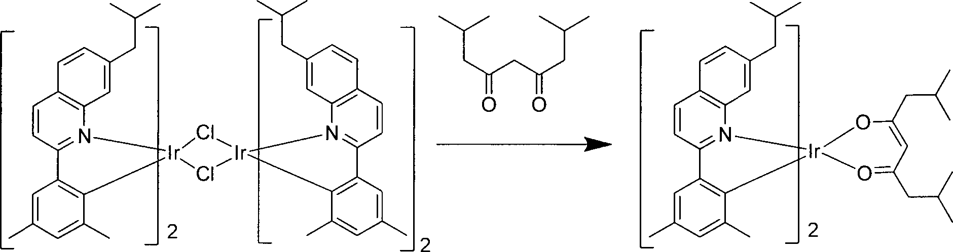
Das dichlorüberbrückte Iridiumdimer aus Schritt 4 (1,0 g, 0,6 mmol), 2,8-Dimethylnonan-4,6-dion (0,8 g, 6 mmol), Na2CO3 (3 g, 12 mmol) und 25 ml 2-Ethoxyethanol wurden in einen Rundkolben von 250 ml eingegeben. Die Reaktionsmischung wurde bei Raumtemperatur 24 Stunden lang gerührt, woraufhin 2 g Celite® und 200 ml Dichlormethan der Reaktionsmischung hinzugegeben wurden, um das Produkt zu lösen. Die Mischung wurde durch ein Bett von Celite® filtriert. Das Filtrat wurde durch einen Siliciumdioxid/Aluminiumoxid-Pfropfen gefiltert und mit Dichlormethan gewaschen. Die geklärte Lösung wurde durch GF/F-Filterpapier filtriert und das Filtrat wurde erhitzt, um den Großteil des Dichiormethans zu entfernen. Isopropanol (20 ml) wurde dann hinzugegeben und die Aufschlämmung wurde auf Raumtemperatur abgekühlt und das Produkt filtriert und mit Isopropanol gewaschen und getrocknet, um 1,1 g (Ausbeute 97%) Rohprodukt zu ergeben. Dieses Produkt wurde zweimal aus Dichiormethan umkristallisiert und dann sublimiert, um die Verbindung 1 zu erhalten. Synthese der Verbindung 2 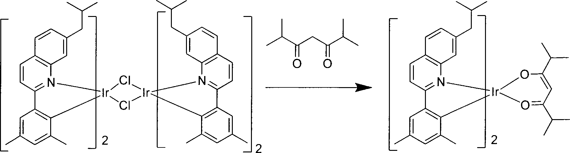
Dichlorüberbrücktes Iridiumdimer aus Schritt 4 aus der vorherigen Synthese (2,75 g, 1,71 mmol), 2,6-Dimethylheptan-3,5-dion (2,67 g, 17,1 mmol), K2CO3 (2,3 g, 34,2 mmol) and 25 ml 2-Ethoxyethanol wurden in einen Rundkolben von 250 ml eingegeben. Die Reaktionsmischung wurde bei Umgebungstemperatur 24 Stunden lang gerührt, woraufhin 2 g Celite® und 200 ml Dichlormethan der Reaktionsmischung hinzugegeben wurden, um das Produkt zu lösen. Die Mischung wurde durch ein Bett von Celite® filtriert. Das Filtrat wurde durch einen Siliciumdioxid/Aluminiumoxid-Pfropfen gefiltert und mit Dichlormethan gewaschen. Die geklärte Lösung wurde dann durch GF/F-Filterpapier filtriert und das Filtrat wurde erhitzt, um den Großteil des Dichlormethans zu entfernen. Isopropanol (20 ml) wurde hinzugegeben und die Aufschlämmung wurde auf Raumtemperatur abgekühlt und das Produkt filtriert und mit Isopropanol gewaschen und getrocknet, um 1,49 g (Ausbeute 97%) Rohprodukt zu ergeben. Dieses Produkt wurde dann zweimal umkristallisiert und dann sublimiert, um die Verbindung 2 zu erhalten.Dichloro-bridged iridium dimer from step 4 from the previous synthesis (2.75 g, 1.71 mmol), 2,6-dimethylheptane-3,5-dione (2.67 g, 17.1 mmol), K 2 CO 3 (2 , 3 g, 34.2 mmol) and 25 ml of 2-ethoxyethanol were placed in a 250 ml round bottom flask. The reaction mixture was stirred for 24 hours at ambient temperature, after which 2 g of Celite ® and 200 ml of dichloromethane, the reaction mixture was added to dissolve the product. The mixture was filtered through a bed of Celite ®. The filtrate was filtered through a silica / alumina plug and washed with dichloromethane. The clarified solution was then filtered through GF / F filter paper and the filtrate was heated to remove most of the dichloromethane. Isopropanol (20 mL) was added and the slurry was cooled to room temperature and the product filtered and washed with isopropanol and dried to give 1.49 g (97% yield) of crude product. This product was then recrystallized twice and then sublimed to obtain compound 2.
Es versteht sich, dass die verschiedenen hierin beschriebenen Ausführungsformen nur als Beispiel dienen und den Umfang der Erfindung nicht einschränken sollen. Beispielsweise können viele der hier beschriebenen Materialien und Strukturen durch andere Materialien und Strukturen ersetzt werden, ohne vom Wesen der Erfindung abzuweichen. Die vorliegende Erfindung, wie beansprucht, kann daher Variationen von den spezifischen Beispielen und bevorzugten hier beschriebenen Ausführungsformen umfassen, wie es einem Fachmann auf dem Gebiet der Technik offensichtlich ist. Es versteht sich, dass verschiedene Theorien, warum die Erfindung funktioniert, nicht als beschränkend aufgefasst werden sollen.It should be understood that the various embodiments described herein are by way of example only and are not intended to limit the scope of the invention. For example, many of the materials and structures described herein may be substituted with other materials and structures without departing from the spirit of the invention. The present invention as claimed may therefore include variations of the specific examples and preferred embodiments described herein, as will be apparent to one skilled in the art. It is understood that various theories of why the invention works should not be construed as limiting.
ZITATE ENTHALTEN IN DER BESCHREIBUNG QUOTES INCLUDE IN THE DESCRIPTION
Diese Liste der vom Anmelder aufgeführten Dokumente wurde automatisiert erzeugt und ist ausschließlich zur besseren Information des Lesers aufgenommen. Die Liste ist nicht Bestandteil der deutschen Patent- bzw. Gebrauchsmusteranmeldung. Das DPMA übernimmt keinerlei Haftung für etwaige Fehler oder Auslassungen.This list of the documents listed by the applicant has been generated automatically and is included solely for the better information of the reader. The list is not part of the German patent or utility model application. The DPMA assumes no liability for any errors or omissions.
Zitierte PatentliteraturCited patent literature
- US 5844363 [0004, 0034] US 5844363 [0004, 0034]
- US 6303238 [0004, 0034] US 6303238 [0004, 0034]
- US 5707745 [0004, 0034, 0037] US 5707745 [0004, 0034, 0037]
- US 7279704 [0014, 0032, 0033, 0041] US 7279704 [0014, 0032, 0033, 0041]
- US 4769292 [0031] US 4769292 [0031]
- US 5703436 [0034] US 5703436 [0034]
- US 6097147 [0034] US 6097147 [0034]
- US 5247190 [0037] US 5247190 [0037]
- US 6091195 [0037] US 6091195 [0037]
- US 5834893 [0037] US 5834893 [0037]
- US 6013982 [0038] US 6013982 [0038]
- US 6087196 [0038] US 6087196 [0038]
- US 6337102 [0038] US 6337102 [0038]
- US 6294398 [0038] US 6294398 [0038]
- US 6468819 [0038] US 6468819 [0038]
Zitierte Nicht-PatentliteraturCited non-patent literature
- Baldo et al., „Highly Efficient Phosphorescent Emission from Organic Electroluminescent Devices,” Nature, vol. 395, 151–154, 1998 [0032] Baldo et al., "Highly Efficient Phosphorescent Emission from Organic Electroluminescent Devices," Nature, vol. 395, 151-154, 1998 [0032]
- („Baldo-I”) und Baldo et al., „Very high-efficiency green organic light-emitting devices based an electrophosphorescence,” Appl. Phys. Lett., vol. 75, No. 3,4-6(1999) („Baldo-II”) [0032] ("Baldo-I") and Baldo et al., "Very high-efficiency green organic light-emitting devices based on electrophosphorescence," Appl. Phys. Lett., Vol. 75, no. 3,4-6 (1999) ("Baldo-II") [0032]
Claims (20)


Applications Claiming Priority (2)
| Application Number | Priority Date | Filing Date | Title |
|---|---|---|---|
| US13/345,285 US9163174B2 (en) | 2012-01-04 | 2012-01-06 | Highly efficient phosphorescent materials |
| US13/345,285 | 2012-01-06 |
Publications (2)
| Publication Number | Publication Date |
|---|---|
| DE102013200085A1 true DE102013200085A1 (en) | 2013-07-11 |
| DE102013200085B4 DE102013200085B4 (en) | 2020-06-18 |
Family
ID=48652749
Family Applications (1)
| Application Number | Title | Priority Date | Filing Date |
|---|---|---|---|
| DE102013200085.5A Active DE102013200085B4 (en) | 2012-01-06 | 2013-01-07 | Highly efficient phosphorescent materials |
Country Status (3)
| Country | Link |
|---|---|
| JP (1) | JP6062741B2 (en) |
| KR (1) | KR102012047B1 (en) |
| DE (1) | DE102013200085B4 (en) |
Families Citing this family (3)
| Publication number | Priority date | Publication date | Assignee | Title |
|---|---|---|---|---|
| US9163174B2 (en) * | 2012-01-04 | 2015-10-20 | Universal Display Corporation | Highly efficient phosphorescent materials |
| US10003033B2 (en) * | 2014-02-18 | 2018-06-19 | Universal Display Corporation | Organic electroluminescent materials and devices |
| KR101646732B1 (en) * | 2014-08-08 | 2016-08-08 | 서울대학교산학협력단 | Organic light-emitting device |
Citations (14)
| Publication number | Priority date | Publication date | Assignee | Title |
|---|---|---|---|---|
| US4769292A (en) | 1987-03-02 | 1988-09-06 | Eastman Kodak Company | Electroluminescent device with modified thin film luminescent zone |
| US5247190A (en) | 1989-04-20 | 1993-09-21 | Cambridge Research And Innovation Limited | Electroluminescent devices |
| US5703436A (en) | 1994-12-13 | 1997-12-30 | The Trustees Of Princeton University | Transparent contacts for organic devices |
| US5707745A (en) | 1994-12-13 | 1998-01-13 | The Trustees Of Princeton University | Multicolor organic light emitting devices |
| US5834893A (en) | 1996-12-23 | 1998-11-10 | The Trustees Of Princeton University | High efficiency organic light emitting devices with light directing structures |
| US5844363A (en) | 1997-01-23 | 1998-12-01 | The Trustees Of Princeton Univ. | Vacuum deposited, non-polymeric flexible organic light emitting devices |
| US6013982A (en) | 1996-12-23 | 2000-01-11 | The Trustees Of Princeton University | Multicolor display devices |
| US6087196A (en) | 1998-01-30 | 2000-07-11 | The Trustees Of Princeton University | Fabrication of organic semiconductor devices using ink jet printing |
| US6091195A (en) | 1997-02-03 | 2000-07-18 | The Trustees Of Princeton University | Displays having mesa pixel configuration |
| US6097147A (en) | 1998-09-14 | 2000-08-01 | The Trustees Of Princeton University | Structure for high efficiency electroluminescent device |
| US6294398B1 (en) | 1999-11-23 | 2001-09-25 | The Trustees Of Princeton University | Method for patterning devices |
| US6303238B1 (en) | 1997-12-01 | 2001-10-16 | The Trustees Of Princeton University | OLEDs doped with phosphorescent compounds |
| US6337102B1 (en) | 1997-11-17 | 2002-01-08 | The Trustees Of Princeton University | Low pressure vapor phase deposition of organic thin films |
| US7279704B2 (en) | 2004-05-18 | 2007-10-09 | The University Of Southern California | Complexes with tridentate ligands |
Family Cites Families (126)
| Publication number | Priority date | Publication date | Assignee | Title |
|---|---|---|---|---|
| US5061569A (en) | 1990-07-26 | 1991-10-29 | Eastman Kodak Company | Electroluminescent device with organic electroluminescent medium |
| US6528187B1 (en) | 1998-09-08 | 2003-03-04 | Fuji Photo Film Co., Ltd. | Material for luminescence element and luminescence element using the same |
| US6830828B2 (en) | 1998-09-14 | 2004-12-14 | The Trustees Of Princeton University | Organometallic complexes as phosphorescent emitters in organic LEDs |
| US6565994B2 (en) | 2000-02-10 | 2003-05-20 | Fuji Photo Film Co., Ltd. | Light emitting device material comprising iridium complex and light emitting device using same material |
| US20020121638A1 (en) | 2000-06-30 | 2002-09-05 | Vladimir Grushin | Electroluminescent iridium compounds with fluorinated phenylpyridines, phenylpyrimidines, and phenylquinolines and devices made with such compounds |
| CN102041001B (en) | 2000-08-11 | 2014-10-22 | 普林斯顿大学理事会 | Organometallic compounds and emission-shifting organic electrophosphorescence |
| US6579630B2 (en) | 2000-12-07 | 2003-06-17 | Canon Kabushiki Kaisha | Deuterated semiconducting organic compounds used for opto-electronic devices |
| JP4307000B2 (en) | 2001-03-08 | 2009-08-05 | キヤノン株式会社 | Metal coordination compound, electroluminescent element and display device |
| JP4310077B2 (en) | 2001-06-19 | 2009-08-05 | キヤノン株式会社 | Metal coordination compound and organic light emitting device |
| DE60232415D1 (en) | 2001-06-20 | 2009-07-02 | Showa Denko Kk | LIGHT-EMITTING MATERIAL AND ORGANIC LUMINAIRE DIODE |
| US7071615B2 (en) | 2001-08-20 | 2006-07-04 | Universal Display Corporation | Transparent electrodes |
| US7250226B2 (en) | 2001-08-31 | 2007-07-31 | Nippon Hoso Kyokai | Phosphorescent compound, a phosphorescent composition and an organic light-emitting device |
| US7166368B2 (en) | 2001-11-07 | 2007-01-23 | E. I. Du Pont De Nemours And Company | Electroluminescent platinum compounds and devices made with such compounds |
| KR100691543B1 (en) | 2002-01-18 | 2007-03-09 | 주식회사 엘지화학 | New material for transporting electron and organic electroluminescent display using the same |
| JP3919583B2 (en) | 2002-04-12 | 2007-05-30 | キヤノン株式会社 | Organic light emitting device |
| US20030230980A1 (en) | 2002-06-18 | 2003-12-18 | Forrest Stephen R | Very low voltage, high efficiency phosphorescent oled in a p-i-n structure |
| US7189989B2 (en) | 2002-08-22 | 2007-03-13 | Fuji Photo Film Co., Ltd. | Light emitting element |
| DE10238903A1 (en) | 2002-08-24 | 2004-03-04 | Covion Organic Semiconductors Gmbh | New heteroaromatic rhodium and iridium complexes, useful in electroluminescent and/or phosphorescent devices as the emission layer and for use in solar cells, photovoltaic devices and organic photodetectors |
| EP2264122A3 (en) | 2002-08-27 | 2011-05-11 | Fujifilm Corporation | Organometallic complexes, organic electroluminescent devices and organic electroluminescent displays |
| US6687266B1 (en) | 2002-11-08 | 2004-02-03 | Universal Display Corporation | Organic light emitting materials and devices |
| EP2248870B1 (en) | 2002-11-26 | 2018-12-26 | Konica Minolta Holdings, Inc. | Organic electroluminscent element and display and illuminator |
| JP4365199B2 (en) | 2002-12-27 | 2009-11-18 | 富士フイルム株式会社 | Organic electroluminescence device |
| JP4365196B2 (en) | 2002-12-27 | 2009-11-18 | 富士フイルム株式会社 | Organic electroluminescence device |
| EP1606296B1 (en) | 2003-03-24 | 2009-08-05 | University Of Southern California | PHENYL-PYRAZOLE COMPLEXES OF Ir |
| US7090928B2 (en) | 2003-04-01 | 2006-08-15 | The University Of Southern California | Binuclear compounds |
| EP1717291A3 (en) | 2003-04-15 | 2007-03-21 | Merck Patent GmbH | Mixtures of matrix materials and organic semiconductors capable of emission, use of the same and electronic components containing said mixtures |
| US7326475B2 (en) | 2003-04-23 | 2008-02-05 | Konica Minolta Holdings, Inc. | Material for organic electroluminescent device, organic electroluminescent device, illuminating device and display |
| US20060186791A1 (en) | 2003-05-29 | 2006-08-24 | Osamu Yoshitake | Organic electroluminescent element |
| EP2924094B1 (en) | 2003-06-02 | 2017-04-05 | UDC Ireland Limited | Organic electroluminescent devices and metal complex compounds |
| JP2005011610A (en) | 2003-06-18 | 2005-01-13 | Nippon Steel Chem Co Ltd | Organic electroluminescent element |
| US20050025993A1 (en) | 2003-07-25 | 2005-02-03 | Thompson Mark E. | Materials and structures for enhancing the performance of organic light emitting devices |
| DE10338550A1 (en) | 2003-08-19 | 2005-03-31 | Basf Ag | Transition metal complexes with carbene ligands as emitters for organic light-emitting diodes (OLEDs) |
| HU0302888D0 (en) | 2003-09-09 | 2003-11-28 | Pribenszky Csaba Dr | In creasing of efficacity of stable storage by freezing of embryos in preimplantation stage with pretreatment by pressure |
| US20060269780A1 (en) | 2003-09-25 | 2006-11-30 | Takayuki Fukumatsu | Organic electroluminescent device |
| KR101044087B1 (en) | 2003-11-04 | 2011-06-27 | 다카사고 고료 고교 가부시키가이샤 | Platinum complex and luminescent element |
| JP4822687B2 (en) | 2003-11-21 | 2011-11-24 | 富士フイルム株式会社 | Organic electroluminescence device |
| US7332232B2 (en) | 2004-02-03 | 2008-02-19 | Universal Display Corporation | OLEDs utilizing multidentate ligand systems |
| KR100963457B1 (en) | 2004-03-11 | 2010-06-17 | 미쓰비시 가가꾸 가부시키가이샤 | Composition for charge-transporting film and ion compound, charge-transporting film and organic electroluminescent device using same, and method for manufacturing organic electroluminescent device and method for producing charge-transporting film |
| TW200531592A (en) | 2004-03-15 | 2005-09-16 | Nippon Steel Chemical Co | Organic electroluminescent device |
| JP4869565B2 (en) | 2004-04-23 | 2012-02-08 | 富士フイルム株式会社 | Organic electroluminescence device |
| US7393599B2 (en) | 2004-05-18 | 2008-07-01 | The University Of Southern California | Luminescent compounds with carbene ligands |
| US7445855B2 (en) | 2004-05-18 | 2008-11-04 | The University Of Southern California | Cationic metal-carbene complexes |
| US7491823B2 (en) | 2004-05-18 | 2009-02-17 | The University Of Southern California | Luminescent compounds with carbene ligands |
| US7655323B2 (en) | 2004-05-18 | 2010-02-02 | The University Of Southern California | OLEDs utilizing macrocyclic ligand systems |
| US7154114B2 (en) | 2004-05-18 | 2006-12-26 | Universal Display Corporation | Cyclometallated iridium carbene complexes for use as hosts |
| US7534505B2 (en) | 2004-05-18 | 2009-05-19 | The University Of Southern California | Organometallic compounds for use in electroluminescent devices |
| WO2005123873A1 (en) | 2004-06-17 | 2005-12-29 | Konica Minolta Holdings, Inc. | Organic electroluminescent device material, organic electroluminescent device, display and illuminating device |
| CA2568667A1 (en) | 2004-06-28 | 2006-01-05 | Ciba Specialty Chemicals Holding Inc. | Electroluminescent metal complexes with triazoles and benzotriazoles |
| US20060008670A1 (en) | 2004-07-06 | 2006-01-12 | Chun Lin | Organic light emitting materials and devices |
| EP2178348B1 (en) | 2004-07-23 | 2012-11-21 | Konica Minolta Holdings, Inc. | Organic electroluminescent element, display and illuminator |
| DE102004057072A1 (en) | 2004-11-25 | 2006-06-01 | Basf Ag | Use of Transition Metal Carbene Complexes in Organic Light Emitting Diodes (OLEDs) |
| WO2006067074A1 (en) | 2004-12-23 | 2006-06-29 | Ciba Specialty Chemicals Holding Inc. | Electroluminescent metal complexes with nucleophilic carbene ligands |
| US7230107B1 (en) | 2004-12-29 | 2007-06-12 | E. I. Du Pont De Nemours And Company | Metal quinoline complexes |
| US8377571B2 (en) | 2005-02-04 | 2013-02-19 | Konica Minolta Holdings, Inc. | Material for organic electroluminescence element, organic electroluminescence element, display device and lighting device |
| KR100803125B1 (en) | 2005-03-08 | 2008-02-14 | 엘지전자 주식회사 | Red phosphorescent compounds and organic electroluminescence devices using the same |
| JP5125502B2 (en) | 2005-03-16 | 2013-01-23 | コニカミノルタホールディングス株式会社 | Organic electroluminescence element material, organic electroluminescence element |
| DE102005014284A1 (en) | 2005-03-24 | 2006-09-28 | Basf Ag | Use of compounds containing aromatic or heteroaromatic rings containing groups via carbonyl groups as matrix materials in organic light-emitting diodes |
| WO2006103874A1 (en) | 2005-03-29 | 2006-10-05 | Konica Minolta Holdings, Inc. | Organic electroluminescent device material, organic electroluminescent device, display and illuminating device |
| US8231983B2 (en) | 2005-04-18 | 2012-07-31 | Konica Minolta Holdings Inc. | Organic electroluminescent device, display and illuminating device |
| US9051344B2 (en) | 2005-05-06 | 2015-06-09 | Universal Display Corporation | Stability OLED materials and devices |
| JP4533796B2 (en) | 2005-05-06 | 2010-09-01 | 富士フイルム株式会社 | Organic electroluminescence device |
| US8586204B2 (en) | 2007-12-28 | 2013-11-19 | Universal Display Corporation | Phosphorescent emitters and host materials with improved stability |
| US8007927B2 (en) | 2007-12-28 | 2011-08-30 | Universal Display Corporation | Dibenzothiophene-containing materials in phosphorescent light emitting diodes |
| US8092924B2 (en) | 2005-05-31 | 2012-01-10 | Universal Display Corporation | Triphenylene hosts in phosphorescent light emitting diodes |
| KR101010846B1 (en) | 2005-06-07 | 2011-01-25 | 신닛테츠가가쿠 가부시키가이샤 | Organic metal complex and organic electroluminescent device using same |
| WO2007002683A2 (en) | 2005-06-27 | 2007-01-04 | E. I. Du Pont De Nemours And Company | Electrically conductive polymer compositions |
| JP5076891B2 (en) | 2005-07-01 | 2012-11-21 | コニカミノルタホールディングス株式会社 | ORGANIC ELECTROLUMINESCENT ELEMENT MATERIAL, ORGANIC ELECTROLUMINESCENT ELEMENT, DISPLAY DEVICE AND LIGHTING DEVICE |
| WO2007028417A1 (en) | 2005-09-07 | 2007-03-15 | Technische Universität Braunschweig | Triplett emitter having condensed five-membered rings |
| JP4887731B2 (en) | 2005-10-26 | 2012-02-29 | コニカミノルタホールディングス株式会社 | Organic electroluminescence element, display device and lighting device |
| US7462406B2 (en) | 2005-11-15 | 2008-12-09 | Eastman Kodak Company | OLED devices with dinuclear copper compounds |
| KR20080085000A (en) | 2005-12-01 | 2008-09-22 | 신닛테츠가가쿠 가부시키가이샤 | Organic electroluminescent device |
| CN102633820B (en) | 2005-12-01 | 2015-01-21 | 新日铁住金化学株式会社 | Compound for organic electroluminescent element and organic electroluminescent element |
| EP2399922B1 (en) | 2006-02-10 | 2019-06-26 | Universal Display Corporation | Metal complexes of cyclometallated imidazo(1,2-f) phenanthridine and diimidazo(1,2-A;1',2'-C)quinazoline ligands and isoelectronic and benzannulated analogs therof |
| JP4823730B2 (en) | 2006-03-20 | 2011-11-24 | 新日鐵化学株式会社 | Luminescent layer compound and organic electroluminescent device |
| EP2018090A4 (en) | 2006-05-11 | 2010-12-01 | Idemitsu Kosan Co | Organic electroluminescent device |
| WO2007142083A1 (en) | 2006-06-02 | 2007-12-13 | Idemitsu Kosan Co., Ltd. | Material for organic electroluminescence element, and organic electroluminescence element using the material |
| JP5589251B2 (en) | 2006-09-21 | 2014-09-17 | コニカミノルタ株式会社 | Organic electroluminescence element material |
| JP4388590B2 (en) | 2006-11-09 | 2009-12-24 | 新日鐵化学株式会社 | Compound for organic electroluminescence device and organic electroluminescence device |
| US8778508B2 (en) | 2006-12-08 | 2014-07-15 | Universal Display Corporation | Light-emitting organometallic complexes |
| EP2437326A3 (en) | 2006-12-13 | 2013-11-13 | Konica Minolta Holdings, Inc. | Organic electroluminescent element, display device and lighting device |
| WO2008101842A1 (en) | 2007-02-23 | 2008-08-28 | Basf Se | Electroluminescent metal complexes with benzotriazoles |
| CN101657518A (en) | 2007-03-08 | 2010-02-24 | 通用显示公司 | phosphorescent materials |
| DE502008002309D1 (en) | 2007-04-26 | 2011-02-24 | Basf Se | SILANE CONTAINS PHENOTHIAZIN S-OXIDE OR PHENOTHIAZIN-S, S-DIOXIDE GROUPS AND THEIR USE IN OLEDS |
| WO2008156879A1 (en) | 2007-06-20 | 2008-12-24 | Universal Display Corporation | Blue phosphorescent imidazophenanthridine materials |
| WO2009000673A2 (en) | 2007-06-22 | 2008-12-31 | Basf Se | Light emitting cu(i) complexes |
| JP5675349B2 (en) | 2007-07-05 | 2015-02-25 | ビーエーエスエフ ソシエタス・ヨーロピアBasf Se | Carbene transition metal complex luminophore and at least one selected from disilylcarbazole, disilyldibenzofuran, disilyldibenzothiophene, disilyldibenzophosphole, disilyldibenzothiophene S-oxide and disilyldibenzothiophene S, S-dioxide Light-emitting diodes containing two compounds |
| US20090045731A1 (en) | 2007-07-07 | 2009-02-19 | Idemitsu Kosan Co., Ltd. | Organic electroluminescence device and material for organic electroluminescence device |
| US8221907B2 (en) | 2007-07-07 | 2012-07-17 | Idemitsu Kosan Co., Ltd. | Chrysene derivative and organic electroluminescent device using the same |
| TW200909560A (en) | 2007-07-07 | 2009-03-01 | Idemitsu Kosan Co | Organic electroluminescence device and material for organic electroluminescence devcie |
| TW200911730A (en) | 2007-07-07 | 2009-03-16 | Idemitsu Kosan Co | Naphthalene derivative, material for organic electroluminescence device, and organic electroluminescence device using the same |
| US8779655B2 (en) | 2007-07-07 | 2014-07-15 | Idemitsu Kosan Co., Ltd. | Organic electroluminescence device and material for organic electroluminescence device |
| US8080658B2 (en) | 2007-07-10 | 2011-12-20 | Idemitsu Kosan Co., Ltd. | Material for organic electroluminescent element and organic electroluminescent element employing the same |
| EP2166584B1 (en) | 2007-07-10 | 2016-06-08 | Idemitsu Kosan Co., Ltd. | Material for organic electroluminescence element, and organic electroluminescence element prepared by using the material |
| US8367850B2 (en) | 2007-08-08 | 2013-02-05 | Universal Display Corporation | Benzo-fused thiophene or benzo-fused furan compounds comprising a triphenylene group |
| JP2009040728A (en) | 2007-08-09 | 2009-02-26 | Canon Inc | Organometallic complex and organic light-emitting element using the same |
| US8956737B2 (en) * | 2007-09-27 | 2015-02-17 | Lg Display Co., Ltd. | Red phosphorescent compound and organic electroluminescent device using the same |
| CN101896494B (en) | 2007-10-17 | 2015-04-08 | 巴斯夫欧洲公司 | Transition metal complexes having bridged carbene ligands and the use thereof in OLEDs |
| US20090101870A1 (en) | 2007-10-22 | 2009-04-23 | E. I. Du Pont De Nemours And Company | Electron transport bi-layers and devices made with such bi-layers |
| US7914908B2 (en) | 2007-11-02 | 2011-03-29 | Global Oled Technology Llc | Organic electroluminescent device having an azatriphenylene derivative |
| JPWO2009063833A1 (en) | 2007-11-15 | 2011-03-31 | 出光興産株式会社 | Benzochrysene derivative and organic electroluminescence device using the same |
| CN101868868A (en) | 2007-11-22 | 2010-10-20 | 出光兴产株式会社 | Organic el element |
| EP2221897A4 (en) | 2007-11-22 | 2012-08-08 | Idemitsu Kosan Co | Organic el element and solution containing organic el material |
| US8221905B2 (en) | 2007-12-28 | 2012-07-17 | Universal Display Corporation | Carbazole-containing materials in phosphorescent light emitting diodes |
| CN105859792A (en) | 2008-02-12 | 2016-08-17 | 巴斯夫欧洲公司 | Electroluminescent metal complexes with dibenzo[f,h]quinoxalines |
| US8318323B2 (en) | 2008-06-05 | 2012-11-27 | Idemitsu Kosan Co., Ltd. | Polycyclic compounds and organic electroluminescence device employing the same |
| US8057919B2 (en) | 2008-06-05 | 2011-11-15 | Idemitsu Kosan Co., Ltd. | Material for organic electroluminescence device and organic electroluminescence device using the same |
| US8049411B2 (en) | 2008-06-05 | 2011-11-01 | Idemitsu Kosan Co., Ltd. | Material for organic electroluminescence device and organic electroluminescence device using the same |
| WO2010027583A1 (en) | 2008-09-03 | 2010-03-11 | Universal Display Corporation | Phosphorescent materials |
| US9034483B2 (en) | 2008-09-16 | 2015-05-19 | Universal Display Corporation | Phosphorescent materials |
| KR101348698B1 (en) | 2008-10-29 | 2014-01-09 | 엘지디스플레이 주식회사 | Red color phosphorescent material and Organic electroluminescent device using the same |
| KR100901888B1 (en) | 2008-11-13 | 2009-06-09 | (주)그라쎌 | Novel organometalic compounds for electroluminescence and organic electroluminescent device using the same |
| US8815415B2 (en) | 2008-12-12 | 2014-08-26 | Universal Display Corporation | Blue emitter with high efficiency based on imidazo[1,2-f] phenanthridine iridium complexes |
| EP2393819B9 (en) | 2009-01-07 | 2017-12-27 | UDC Ireland Limited | Silyl and heteroatom substituted compounds selected from carbazoles, dibenzofurans, dibenzothiophenes and dibenzo phospholes and the application thereof in organic electronics |
| US9067947B2 (en) | 2009-01-16 | 2015-06-30 | Universal Display Corporation | Organic electroluminescent materials and devices |
| DE102009007038A1 (en) | 2009-02-02 | 2010-08-05 | Merck Patent Gmbh | metal complexes |
| KR101511072B1 (en) | 2009-03-20 | 2015-04-10 | 롬엔드하스전자재료코리아유한회사 | Novel organic electroluminescent compounds and organic electroluminescent device using the same |
| US8722205B2 (en) | 2009-03-23 | 2014-05-13 | Universal Display Corporation | Heteroleptic iridium complex |
| US8586203B2 (en) | 2009-05-20 | 2013-11-19 | Universal Display Corporation | Metal complexes with boron-nitrogen heterocycle containing ligands |
| DE102009049587A1 (en) | 2009-10-16 | 2011-04-21 | Merck Patent Gmbh | metal complexes |
| US20120205645A1 (en) | 2009-10-28 | 2012-08-16 | Basf Se | Heteroleptic carbene complexes and the use thereof in organic electronics |
| JP4617393B1 (en) * | 2010-01-15 | 2011-01-26 | 富士フイルム株式会社 | Organic electroluminescence device |
| US8288187B2 (en) | 2010-01-20 | 2012-10-16 | Universal Display Corporation | Electroluminescent devices for lighting applications |
| US9156870B2 (en) | 2010-02-25 | 2015-10-13 | Universal Display Corporation | Phosphorescent emitters |
| WO2011136755A1 (en) * | 2010-04-28 | 2011-11-03 | Universal Display Corporation | Depositing premixed materials |
| KR102004629B1 (en) | 2010-08-20 | 2019-07-26 | 유니버셜 디스플레이 코포레이션 | Bicarbazole compounds for oleds |
| US9217004B2 (en) * | 2011-11-21 | 2015-12-22 | Universal Display Corporation | Organic light emitting materials |
-
2013
- 2013-01-02 KR KR1020130000225A patent/KR102012047B1/en active IP Right Grant
- 2013-01-04 JP JP2013000115A patent/JP6062741B2/en active Active
- 2013-01-07 DE DE102013200085.5A patent/DE102013200085B4/en active Active
Patent Citations (15)
| Publication number | Priority date | Publication date | Assignee | Title |
|---|---|---|---|---|
| US4769292A (en) | 1987-03-02 | 1988-09-06 | Eastman Kodak Company | Electroluminescent device with modified thin film luminescent zone |
| US5247190A (en) | 1989-04-20 | 1993-09-21 | Cambridge Research And Innovation Limited | Electroluminescent devices |
| US5703436A (en) | 1994-12-13 | 1997-12-30 | The Trustees Of Princeton University | Transparent contacts for organic devices |
| US5707745A (en) | 1994-12-13 | 1998-01-13 | The Trustees Of Princeton University | Multicolor organic light emitting devices |
| US6013982A (en) | 1996-12-23 | 2000-01-11 | The Trustees Of Princeton University | Multicolor display devices |
| US5834893A (en) | 1996-12-23 | 1998-11-10 | The Trustees Of Princeton University | High efficiency organic light emitting devices with light directing structures |
| US5844363A (en) | 1997-01-23 | 1998-12-01 | The Trustees Of Princeton Univ. | Vacuum deposited, non-polymeric flexible organic light emitting devices |
| US6091195A (en) | 1997-02-03 | 2000-07-18 | The Trustees Of Princeton University | Displays having mesa pixel configuration |
| US6337102B1 (en) | 1997-11-17 | 2002-01-08 | The Trustees Of Princeton University | Low pressure vapor phase deposition of organic thin films |
| US6303238B1 (en) | 1997-12-01 | 2001-10-16 | The Trustees Of Princeton University | OLEDs doped with phosphorescent compounds |
| US6087196A (en) | 1998-01-30 | 2000-07-11 | The Trustees Of Princeton University | Fabrication of organic semiconductor devices using ink jet printing |
| US6097147A (en) | 1998-09-14 | 2000-08-01 | The Trustees Of Princeton University | Structure for high efficiency electroluminescent device |
| US6294398B1 (en) | 1999-11-23 | 2001-09-25 | The Trustees Of Princeton University | Method for patterning devices |
| US6468819B1 (en) | 1999-11-23 | 2002-10-22 | The Trustees Of Princeton University | Method for patterning organic thin film devices using a die |
| US7279704B2 (en) | 2004-05-18 | 2007-10-09 | The University Of Southern California | Complexes with tridentate ligands |
Non-Patent Citations (2)
| Title |
|---|
| ("Baldo-I") und Baldo et al., "Very high-efficiency green organic light-emitting devices based an electrophosphorescence," Appl. Phys. Lett., vol. 75, No. 3,4-6(1999) ("Baldo-II") |
| Baldo et al., "Highly Efficient Phosphorescent Emission from Organic Electroluminescent Devices," Nature, vol. 395, 151-154, 1998 |
Also Published As
| Publication number | Publication date |
|---|---|
| DE102013200085B4 (en) | 2020-06-18 |
| KR102012047B1 (en) | 2019-08-19 |
| JP6062741B2 (en) | 2017-01-18 |
| KR20130081240A (en) | 2013-07-16 |
| JP2013142088A (en) | 2013-07-22 |
Similar Documents
| Publication | Publication Date | Title |
|---|---|---|
| DE112011101663B4 (en) | Azaborine compounds as host materials and dopants for Pholeds | |
| JP6541819B2 (en) | Heteroleptic iridium carbene complex and light emitting device using the same | |
| DE112011103404B4 (en) | Novel 3,9-linked oligocarbazoles and OLEDs containing these novel oligocarbazoles | |
| DE112010005815B4 (en) | Bicarbazole compounds for OLEDs | |
| DE102012220691B4 (en) | TRIPHENYLENSILANWIRTE | |
| DE112012002237B4 (en) | Host Materials for OLEDS | |
| JP6427623B2 (en) | Organic light emitting material | |
| JP6332904B2 (en) | New organic light emitting materials | |
| DE112011101447T5 (en) | Bicarbazole containing compounds for OLEDs | |
| DE102013019465A1 (en) | ORGANIC ELECTROLUMINESCENCE DEVICE WITH DELAYED FLUORESCENCE | |
| DE102013208026A1 (en) | Asymmetric hosts with triarylsilane side chains | |
| DE102016201672A1 (en) | Organic electroluminescent materials and devices | |
| DE102019125398A1 (en) | ORGANIC LUMINESCENT MATERIALS CONTAINING NEW AUXILIARY LIGANDS | |
| DE112011101498T5 (en) | Triphenylene-benzofuran / benzothiophene / benzoselenophen compounds having substituents which combine to form fused rings | |
| JP6396147B2 (en) | Organic electroluminescent material and device | |
| DE112011101983T5 (en) | OLED with delayed fluorescence | |
| DE102020205833B4 (en) | Organic luminescent material incorporating a 3-deuterium substituted isoquinoline ligand | |
| WO2012102967A1 (en) | Aza - dibenzothiophene, aza - dibenzofuran and aza - dibenzoselenophene derivatives for use in oled ' s | |
| DE102020205828B4 (en) | Metal complex containing three different ligands | |
| DE102020205832A1 (en) | Organic luminescent material that includes a 6-silyl substituted isoquinoline ligand | |
| DE102013214144B4 (en) | Diarylamino-substituted metal complexes | |
| DE102021110753A1 (en) | Light emitting material with a polycyclic ligand | |
| DE102014001468A1 (en) | HETEROLEPTIC PHENYL BENZIMIDAZOLE COMPLEX | |
| DE102013003605B4 (en) | Secondary hole transport layer with tricarbazole compounds | |
| KR20160037776A (en) | Organic electroluminescent materials and devices |
Legal Events
| Date | Code | Title | Description |
|---|---|---|---|
| R012 | Request for examination validly filed | ||
| R016 | Response to examination communication | ||
| R082 | Change of representative |
Representative=s name: MAIWALD GMBH, DE Representative=s name: MAIWALD PATENTANWALTS- UND RECHTSANWALTSGESELL, DE |
|
| R016 | Response to examination communication | ||
| R018 | Grant decision by examination section/examining division | ||
| R020 | Patent grant now final |