DE102013204390A1 - Blasted cathode of a liquid electrolytic capacitor - Google Patents
Blasted cathode of a liquid electrolytic capacitor Download PDFInfo
- Publication number
- DE102013204390A1 DE102013204390A1 DE201310204390 DE102013204390A DE102013204390A1 DE 102013204390 A1 DE102013204390 A1 DE 102013204390A1 DE 201310204390 DE201310204390 DE 201310204390 DE 102013204390 A DE102013204390 A DE 102013204390A DE 102013204390 A1 DE102013204390 A1 DE 102013204390A1
- Authority
- DE
- Germany
- Prior art keywords
- metal substrate
- acid
- substrate
- abrasive
- micro
- Prior art date
- Legal status (The legal status is an assumption and is not a legal conclusion. Google has not performed a legal analysis and makes no representation as to the accuracy of the status listed.)
- Withdrawn
Links
Images


Classifications
-
- H—ELECTRICITY
- H01—ELECTRIC ELEMENTS
- H01G—CAPACITORS; CAPACITORS, RECTIFIERS, DETECTORS, SWITCHING DEVICES OR LIGHT-SENSITIVE DEVICES, OF THE ELECTROLYTIC TYPE
- H01G9/00—Electrolytic capacitors, rectifiers, detectors, switching devices, light-sensitive or temperature-sensitive devices; Processes of their manufacture
- H01G9/004—Details
- H01G9/04—Electrodes or formation of dielectric layers thereon
- H01G9/042—Electrodes or formation of dielectric layers thereon characterised by the material
- H01G9/0425—Electrodes or formation of dielectric layers thereon characterised by the material specially adapted for cathode
-
- H—ELECTRICITY
- H01—ELECTRIC ELEMENTS
- H01G—CAPACITORS; CAPACITORS, RECTIFIERS, DETECTORS, SWITCHING DEVICES OR LIGHT-SENSITIVE DEVICES, OF THE ELECTROLYTIC TYPE
- H01G4/00—Fixed capacitors; Processes of their manufacture
- H01G4/002—Details
- H01G4/005—Electrodes
-
- H—ELECTRICITY
- H01—ELECTRIC ELEMENTS
- H01G—CAPACITORS; CAPACITORS, RECTIFIERS, DETECTORS, SWITCHING DEVICES OR LIGHT-SENSITIVE DEVICES, OF THE ELECTROLYTIC TYPE
- H01G9/00—Electrolytic capacitors, rectifiers, detectors, switching devices, light-sensitive or temperature-sensitive devices; Processes of their manufacture
- H01G9/004—Details
- H01G9/04—Electrodes or formation of dielectric layers thereon
- H01G9/042—Electrodes or formation of dielectric layers thereon characterised by the material
-
- H—ELECTRICITY
- H01—ELECTRIC ELEMENTS
- H01G—CAPACITORS; CAPACITORS, RECTIFIERS, DETECTORS, SWITCHING DEVICES OR LIGHT-SENSITIVE DEVICES, OF THE ELECTROLYTIC TYPE
- H01G9/00—Electrolytic capacitors, rectifiers, detectors, switching devices, light-sensitive or temperature-sensitive devices; Processes of their manufacture
- H01G9/004—Details
- H01G9/04—Electrodes or formation of dielectric layers thereon
- H01G9/048—Electrodes or formation of dielectric layers thereon characterised by their structure
- H01G9/055—Etched foil electrodes
-
- H—ELECTRICITY
- H01—ELECTRIC ELEMENTS
- H01G—CAPACITORS; CAPACITORS, RECTIFIERS, DETECTORS, SWITCHING DEVICES OR LIGHT-SENSITIVE DEVICES, OF THE ELECTROLYTIC TYPE
- H01G9/00—Electrolytic capacitors, rectifiers, detectors, switching devices, light-sensitive or temperature-sensitive devices; Processes of their manufacture
- H01G9/145—Liquid electrolytic capacitors
-
- H—ELECTRICITY
- H01—ELECTRIC ELEMENTS
- H01G—CAPACITORS; CAPACITORS, RECTIFIERS, DETECTORS, SWITCHING DEVICES OR LIGHT-SENSITIVE DEVICES, OF THE ELECTROLYTIC TYPE
- H01G9/00—Electrolytic capacitors, rectifiers, detectors, switching devices, light-sensitive or temperature-sensitive devices; Processes of their manufacture
- H01G9/004—Details
- H01G9/022—Electrolytes; Absorbents
- H01G9/025—Solid electrolytes
- H01G9/028—Organic semiconducting electrolytes, e.g. TCNQ
Abstract
Ein Flüssigelektrolytkondensator wird bereitgestellt, der einen porösen Anodenkörper, welcher eine dielektrische Schicht enthält, einen Elektrolyten und eine Kathode, die ein Metallsubstrat enthält, auf dem sich eine leitfähige Beschichtung befindet, umfasst. Vor der Auftragung der leitfähigen Beschichtung wird das Metallsubstrat mit Schleifkörpern gestrahlt, um die Fähigkeit des Substrats, an der Beschichtung zu haften, zu erhöhen. Das mikroaufgeraute Metallsubstrat kann nach dem Strahlen so behandelt werden, dass im Wesentlichen die gesamten Schleifkörper entfernt werden. Dies wird dadurch erreicht, dass das Metallsubstrat zur Entfernung der Teilchen mit einer Extraktionslösung in Kontakt gebracht wird, und auch dadurch, dass die Art der Schleifkörper gezielt gesteuert wird, so dass sie in der Lösung dispergierbar (z. B. löslich) sind.A liquid electrolytic capacitor is provided which comprises a porous anode body containing a dielectric layer, an electrolyte and a cathode containing a metal substrate having a conductive coating thereon. Prior to the application of the conductive coating, the metal substrate is blasted with abrasive articles to increase the ability of the substrate to adhere to the coating. The micro-roughened metal substrate, after blasting, may be treated to remove substantially all of the abrasive articles. This is accomplished by contacting the metal substrate with an extraction solution to remove the particles, and also by selectively controlling the type of abrasive bodies so that they are dispersible (e.g., soluble) in the solution.
Description
Verwandte AnmeldungenRelated applications
Die vorliegende Anmeldung beansprucht die Priorität der am 16. März 2012 eingereichten vorläufigen US-Anmeldung Serial Nr. 61/611,738, auf die hier ausdrücklich Bezug genommen wird.The present application claims priority to US Provisional Application Serial No. 61 / 611,738 filed Mar. 16, 2012, which is incorporated herein by reference.
Hintergrund der ErfindungBackground of the invention
Flüssigkeitskondensatoren werden aufgrund ihrer volumetrischen Effizienz, Zuverlässigkeit und Verfahrenskompatibilität zunehmend bei der Gestaltung von Schaltungen verwendet. Flüssigkeitskondensatoren haben typischerweise eine größere Kapazität pro Volumeneinheit als bestimmte andere Arten von Kondensatoren, wodurch sie wertvoll für elektrische Schaltungen mit hoher Stromstärke, hoher Leistung und niedriger Frequenz sind. Ein Typ von Flüssigkeitskondensator, der entwickelt wurde, ist ein Flüssigelektrolytkondensator, der eine Ventilmetallanode, eine Kathode und einen flüssigen Elektrolyten umfasst. Die Einzelzellspannung bei dieser Art von Kondensator ist aufgrund der Bildung eines dielektrischen Metalloxidfilms über der Anodenoberfläche im Allgemeinen höher. Flüssigelektrolytkondensatoren bieten häufig eine gute Kombination von hoher Kapazität mit einem niedrigen Leckstrom. Ein anderer Typ Flüssigkeitskondensator ist ein symmetrischer Flüssigkeitskondensator, bei dem die Anode und die Kathode bezüglich Struktur und Zusammensetzung gleich sind. Die Einzelzellspannung bei dieser Art von Kondensator ist aufgrund der unvermeidlichen Zersetzung des Elektrolyten bei hoher Spannung im Allgemeinen gering. Ob elektrolytisch oder symmetrisch, die Kathoden von Flüssigkeitskondensatoren umfassen jedoch typischerweise ein Substrat und eine Beschichtung, die über einen faradischen oder nichtfaradischen Mechanismus (z. B. Doppelschichtbildung) für eine hohe Kapazität sorgt. Herkömmliche Beschichtungen umfassen Aktivkohle, Metalloxide (z. B. Rutheniumoxid) und dergleichen. Leider können sich die Beschichtungen jedoch unter bestimmten Bedingungen, wie in Gegenwart von wässrigen Elektrolyten, leicht ablösen.Liquid capacitors are increasingly being used in circuit design because of their volumetric efficiency, reliability and process compatibility. Liquid capacitors typically have a larger capacitance per unit volume than certain other types of capacitors, making them valuable for high current, high power, and low frequency electrical circuits. One type of liquid condenser that has been developed is a liquid electrolytic capacitor that includes a valve metal anode, a cathode, and a liquid electrolyte. The single cell voltage in this type of capacitor is generally higher due to the formation of a metal oxide dielectric film over the anode surface. Liquid electrolytic capacitors often provide a good combination of high capacity with a low leakage current. Another type of liquid condenser is a symmetrical liquid condenser in which the anode and the cathode are the same in structure and composition. The single cell voltage in this type of capacitor is generally low due to the unavoidable decomposition of the electrolyte at high voltage. However, whether electrolytic or symmetrical, the cathodes of liquid capacitors typically include a substrate and a coating that provides high capacitance via a faradic or non-faradic mechanism (eg, bilayer formation). Conventional coatings include activated carbon, metal oxides (eg, ruthenium oxide), and the like. Unfortunately, however, under certain conditions, such as in the presence of aqueous electrolytes, the coatings can easily peel off.
Daher besteht immer noch ein Bedürfnis nach einem Hochspannungs-Flüssigelektrolytkondensator, der eine gute mechanische Robustheit und gute elektrische Eigenschaften besitzt.Therefore, there is still a need for a high voltage liquid electrolytic capacitor that has good mechanical ruggedness and good electrical properties.
Kurzbeschreibung der ErfindungBrief description of the invention
Gemäß einer Ausführungsform der vorliegenden Erfindung wird ein Verfahren zur Bildung einer Kathode eines Flüssigelektrolytkondensators offenbart. Das Verfahren umfasst das Abstrahlen eines Metallsubstrats mit einer Vielzahl von Schleifkörpern zur Bildung einer mikroaufgerauten Oberfläche, die eine Vielzahl von Grübchen aufweist. Die mikroaufgeraute Oberfläche wird mit einer Extraktionslösung in Kontakt gebracht, wobei die Schleifkörper in der Extraktionslösung dispergiert werden. Daher entsteht eine leitfähige Beschichtung auf der mikroaufgerauten Oberfläche.According to one embodiment of the present invention, a method of forming a cathode of a liquid electrolytic capacitor is disclosed. The method comprises radiating a metal substrate having a plurality of abrasive bodies to form a micro-roughened surface having a plurality of dimples. The micro-roughened surface is brought into contact with an extraction solution, whereby the abrasive particles are dispersed in the extraction solution. Therefore, a conductive coating is formed on the micro-roughened surface.
Gemäß einer anderen Ausführungsform der vorliegenden Erfindung wird ein Flüssigelektrolytkondensator offenbart, der einen porösen Anodenkörper, welcher eine durch anodische Oxidation gebildete dielektrische Schicht enthält, einen flüssigen Arbeitselektrolyten und ein Metallsubstrat, innerhalb dessen sich die Anode und der flüssige Elektrolyt befinden, umfasst. Das Metallsubstrat definiert eine innere Oberfläche, die eine Vielzahl von durch Strahlen mit Schleifkörpern gebildeten Grübchen enthält. Nur etwa 15% oder weniger der Oberfläche sind durch die Schleifkörper definiert. Eine leitfähige Beschichtung befindet sich auch auf der inneren Oberfläche des Metallsubstrats und innerhalb von dessen Grübchen.According to another embodiment of the present invention, there is disclosed a liquid electrolytic capacitor comprising a porous anode body containing a dielectric layer formed by anodic oxidation, a liquid working electrolyte, and a metal substrate having the anode and the liquid electrolyte therein. The metal substrate defines an inner surface containing a plurality of pits formed by abrasive blasting. Only about 15% or less of the surface area is defined by the abrasive particles. A conductive coating is also on the inside surface of the metal substrate and within its dimple.
Weitere Merkmale und Aspekte der vorliegenden Erfindung sind im Folgenden ausführlicher beschrieben.Further features and aspects of the present invention are described in more detail below.
Kurzbeschreibung der ZeichnungenBrief description of the drawings
Im Rest der Beschreibung und unter Bezugnahme auf die Begleitzeichnungen ist eine vollständige und nacharbeitbare Offenbarung der vorliegenden Erfindung einschließlich ihrer besten Realisierung für den Fachmann insbesondere dargelegt; dabei sind:In the remainder of the specification and with reference to the accompanying drawings, a complete and reproducible disclosure of the present invention, including the best mode of realization thereof, will be specifically presented to those skilled in the art; are:
Bei mehrfacher Verwendung von Bezugszeichen in der vorliegenden Beschreibung und den Zeichnungen sollen diese dieselben oder analoge Merkmale oder Elemente der vorliegenden Erfindung repräsentieren.When multiple references are used in the present specification and drawings, they are intended to represent the same or analogous features or elements of the present invention.
Ausführliche Beschreibung von repräsentativen AusführungsformenDetailed description of representative embodiments
Der Fachmann sollte sich darüber im Klaren sein, dass die vorliegende Diskussion nur eine Beschreibung von beispielhaften Ausführungsformen ist und die breiteren Aspekte der vorliegenden Erfindung nicht einschränken soll.It should be understood by those skilled in the art that the present discussion is only a description of exemplary embodiments and is not intended to limit the broader aspects of the present invention.
Die vorliegende Erfindung bezieht sich allgemein auf einen Flüssigelektrolytkondensator, der einen porösen Anodenkörper, welcher eine dielektrische Schicht enthält, einen Elektrolyten und eine Kathode, die ein Metallsubstrat enthält, auf dem sich eine leitfähige Beschichtung befindet, umfasst. Vor der Auftragung der leitfähigen Beschichtung wird das Metallsubstrat mit Schleifkörpern gestrahlt, um die Fähigkeit des Substrats, an der Beschichtung zu haften, zu erhöhen. Zum Beispiel kann das Strahlen zu einer Oberfläche führen, die gleichmäßig und makroskopisch glatt ist, wodurch die Konsistenz der darauf gebildeten leitfähigen Beschichtung erhöht wird. Die gestrahlte Oberfläche besitzt zwar einen gewissen Grad von Glätte, ist aber dennoch mikroaufgeraut, so dass sie eine Vielzahl von Grübchen enthält. Die Anwesenheit der Grübchen auf dem Substrat erhöht den Grad des Kontakts zwischen der leitfähigen Beschichtung und dem Metallsubstrat, was zu einer verbesserten mechanischen Robustheit und verbesserten elektrischen Eigenschaften (z. B. reduziertem äquivalenten Serienwiderstand und Leckstrom) führt.The present invention generally relates to a liquid electrolytic capacitor comprising a porous anode body containing a dielectric layer, an electrolyte, and a cathode including a metal substrate having a conductive coating thereon. Prior to the application of the conductive coating, the metal substrate is blasted with abrasive articles to increase the ability of the substrate to adhere to the coating. For example, the blasting may result in a surface that is uniform and macroscopically smooth, thereby increasing the consistency of the conductive coating formed thereon. Although the blasted surface has some degree of smoothness, it is still micro-roughened to contain a variety of pits. The presence of the dimples on the substrate increases the degree of contact between the conductive coating and the metal substrate, resulting in improved mechanical robustness and improved electrical properties (eg, reduced equivalent series resistance and leakage current).
Die Erfinder haben auch herausgefunden, dass das mikroaufgeraute Metallsubstrat nach dem Strahlen so behandelt werden kann, dass im Wesentlichen die gesamten Schleifkörper entfernt werden. Dies wird dadurch erreicht, dass das Metallsubstrat zur Entfernung der Teilchen mit einer Extraktionslösung in Kontakt gebracht wird, und auch dadurch, dass die Art der Schleifkörper gezielt gesteuert wird, so dass sie in der Lösung dispergierbar (z. B. löslich) sind. Auf diese Weise lassen sich alle Teilchen, die möglicherweise während des Strahlens innerhalb der Grübchen eingebettet oder eingeschlossen wurden, durch Kontakt mit der Extraktionslösung leichter entfernen. Dadurch wird die Anzahl der Grübchen, die zum Kontakt mit der leitfähigen Beschichtung frei bleiben können, erhöht, wodurch die verfügbare Oberfläche und der Grad der Oberflächenhaftung zwischen dem Metallsubstrat und der leitfähigen Beschichtung verstärkt werden. Die erhöhte Oberfläche ermöglicht eine erhöhte Kathodenkapazität bei einer gegebenen Größe und/oder Kondensatoren mit einer reduzierten Größe für eine gegebene Kapazität. Falls gewünscht, können die Schleifkörper auch leitfähig sein, so dass der elektrische Kontakt zwischen dem Metallsubstrat und der leitfähigen Beschichtung auch dann nicht beeinträchtigt wird, wenn ein kleiner Teil auf der Oberfläche des Substrats verbleibt.The inventors have also found that the micro-roughened metal substrate after blasting can be treated to remove substantially all of the abrasive grits. This is accomplished by contacting the metal substrate with an extraction solution to remove the particles, and also by selectively controlling the type of abrasive bodies so that they are dispersible (e.g., soluble) in the solution. In this way, any particles that may have been embedded or trapped within the pits during blasting are more easily removed by contact with the extraction solution. This increases the number of pits that can remain free to contact the conductive coating, thereby increasing the available surface area and the degree of surface adhesion between the metal substrate and the conductive coating. The increased surface area allows increased cathode capacity for a given size and / or capacitors of reduced size for a given capacitance. If desired, the abrasive bodies may also be conductive, so that the electrical contact between the metal substrate and the conductive coating is not affected even if a small part remains on the surface of the substrate.
Es werden jetzt verschiedene Ausführungsformen der vorliegenden Erfindung ausführlicher beschrieben.Various embodiments of the present invention will now be described in more detail.
I. KathodeI. cathode
A. MetallsubstratA. Metal substrate
Das Metallsubstrat der Kathode kann ein Metall, wie Tantal, Mob, Aluminium, Nickel, Hafnium, Titan, Kupfer, Silber, Stahl (z. B. Edelstahl), Legierungen davon (z. B. elektrisch leitfähige Oxide), Verbundstoffe davon (z. B. mit elektrisch leitfähigem Oxid beschichtetes Metall) usw. umfassen. Titan und Tantal sowie Legierungen davon sind zur Verwendung in der vorliegenden Erfindung besonders gut geeignet. Die geometrische Konfiguration des Substrats kann im Allgemeinen variieren, wie dem Fachmann wohlbekannt ist, wie in Form eines Behälters, Bechers, Folie, Blech, Sieb, Netz usw. In einer Ausführungsform zum Beispiel bildet das Metallsubstrat ein Gehäuse mit einer im Wesentlichen zylindrischen Form. Man sollte sich jedoch darüber im Klaren sein, dass in der vorliegenden Erfindung jede geometrische Konfiguration eingesetzt werden kann, wie D-förmig, rechteckig, dreieckig, prismatisch usw. Das Gehäuse kann gegebenenfalls einen Deckel umfassen, der die Anode und den Elektrolyten bedeckt und aus demselben oder einem anderen Material als das Gehäuse gebildet sein kann.The metal substrate of the cathode may be a metal such as tantalum, mob, aluminum, nickel, hafnium, titanium, copper, silver, steel (eg, stainless steel), alloys thereof (e.g., electrically conductive oxides), composites thereof (e.g. B. coated with electrically conductive oxide metal) and so on. Titanium and tantalum and alloys thereof are particularly well suited for use in the present invention. The geometric configuration of the substrate may generally vary, as is well known to those skilled in the art, such as a container, cup, foil, sheet, mesh, mesh, etc. In one embodiment, for example, the metal substrate forms a housing having a substantially cylindrical shape. It should be understood, however, that in the present invention any geometric configuration may be employed, such as D-shaped, rectangular, triangular, prismatic, etc. The housing may optionally include a lid covering and extending the anode and the electrolyte may be formed the same or a different material than the housing.
Unabhängig von seiner besonderen Form wird das Substrat mikroaufgeraut, indem man wenigstens einen Teil einer Oberfläche des Substrats mit Schleifkörpern abstrahlt oder dieselben dagegen schleudert. Wie bereits erwähnt, werden die Schleifkörper in der vorliegenden Erfindung so gewählt, dass sie im Allgemeinen in der zur Entfernung der Teilchen verwendeten Extraktionslösung dispergierbar (z. B. löslich) sind. Beispiele für solche Teilchen sind zum Beispiel etwa Keramikteilchen, wie solche, die aus einem Aluminiumoxid, Manganoxid (z. B. Mangandioxid), Nioboxid (z. B. Niobdioxid, Niobmonoxid usw.) usw. gebildet werden, polymere Teilchen sowie Kombinationen davon. Von diesen sind Teilchen, die leitfähig sind, für die Verwendung in der vorliegenden Erfindung besonders gut geeignet, so dass sie den Stromweg zwischen der leitfähigen Beschichtung und dem Substrat auch dann nicht beeinträchtigen, wenn sie auf dem Substrat verbleiben. Beispiele für solche leitfähigen Teilchen sind zum Beispiel etwa Mangandioxid, Niobmonoxid, Niobdioxid usw. Mangandioxid kann besonders gut geeignet sein, da es leitfähig und in sauren Lösungen leicht löslich ist.Regardless of its particular shape, the substrate is micro-roughened by radiating or spinning at least a portion of a surface of the substrate with abrasive articles. As already mentioned, the abrasive articles in the present invention are chosen to be general are dispersible (e.g., soluble) in the extraction solution used to remove the particles. Examples of such particles include, for example, ceramic particles such as those formed from an alumina, manganese oxide (e.g., manganese dioxide), niobium oxide (e.g., niobium dioxide, niobium monoxide, etc.), etc., polymeric particles, and combinations thereof. Of these, particles that are conductive are particularly well-suited for use in the present invention so that they do not interfere with the current path between the conductive coating and the substrate, even if they remain on the substrate. Examples of such conductive particles are, for example, manganese dioxide, niobium monoxide, niobium dioxide, etc. Manganese dioxide may be particularly well suited because it is conductive and easily soluble in acidic solutions.
Die zum Strahlen der Oberfläche mit den Schleifkörpern eingesetzten Verfahren können gezielt gesteuert werden, um die gewünschten Merkmale zu erreichen. Zu den geeigneten Verfahren gehören zum Beispiel Sandstrahlen, Perlstrahlen, Pelletstrahlen usw. Sandstrahltechniken sind zur Verwendung in der vorliegenden Erfindung besonders gut geeignet und beinhalten im Allgemeinen das Schleudern eines Stroms der Schleifkörper durch eine Düse gegen die Oberfläche des Substrats. Die Größe der Schleifkörper kann auf der Grundlage der Art des Substrats, des eingesetzten Drucks und der gewünschten Eigenschaften des fertigen Substrats ausgewählt werden. Zum Beispiel können die Schleifkörper eine mittlere Größe von etwa 25 Mikrometer bis etwa 200 Mikrometer, in einigen Ausführungsformen etwa 40 bis etwa 150 Mikrometer und in einigen Ausführungsformen etwa 50 bis etwa 100 Mikrometer aufweisen. Weiterhin können der Druck und die Zeit, unter dem bzw. während der die Schleifkörper gegen die Oberfläche geschleudert werden, im Bereich von etwa 1 bis etwa 50 psi und in einigen Ausführungsformen etwa 10 bis etwa 35 psi während einer Zeitdauer von etwa 1 bis etwa 50 Sekunden, in einigen Ausführungsformen etwa 5 bis etwa 40 Sekunden und in einigen Ausführungsformen etwa 10 bis etwa 30 Sekunden liegen. Unter solchen Bedingungen kann der Abstand, um den die Strahldüse von der Oberfläche des Metallsubstrats entfernt ist, auch so gesteuert werden, dass die gewünschte Grübchenbildung erreicht wird, wie etwa 0,1 bis etwa 5 Zoll von der Oberfläche des Substrats. Die Düse kann stationär sein, oder sie kann während der Anwendung der Schleifkörper relativ zum Substrat bewegt werden. Wenn die innere Oberfläche eines zylindrischen Gehäuses gestrahlt wird, kann zum Beispiel die Düse gedreht werden, oder sie kann stationär bleiben, während das Gehäuse gedreht wird. Im Allgemeinen können ein oder mehrere Strahlschritte eingesetzt werden.The methods used to blast the surface with the abrasive bodies can be selectively controlled to achieve the desired characteristics. Suitable methods include, for example, sandblasting, bead blasting, pellet blasting, etc. Sandblasting techniques are particularly well suited for use in the present invention and generally involve spinning a stream of abrasive articles through a nozzle against the surface of the substrate. The size of the abrasive article may be selected based on the type of substrate, the pressure employed, and the desired properties of the finished substrate. For example, the abrasive articles may have an average size of from about 25 micrometers to about 200 micrometers, in some embodiments, from about 40 to about 150 micrometers, and in some embodiments, from about 50 to about 100 micrometers. Further, the pressure and time that the abrasive articles are spun against the surface can range from about 1 to about 50 psi, and in some embodiments, from about 10 to about 35 psi over a period of about 1 to about 50 Seconds, in some embodiments about 5 to about 40 seconds and in some embodiments about 10 to about 30 seconds. Under such conditions, the distance that the jet nozzle is away from the surface of the metal substrate may also be controlled to achieve the desired pitting, such as from about 0.1 to about 5 inches from the surface of the substrate. The nozzle may be stationary, or it may be moved relative to the substrate during application of the abrasive bodies. For example, when the inner surface of a cylindrical housing is blasted, the nozzle may be rotated, or it may remain stationary while the housing is rotated. In general, one or more blasting steps can be used.
Sobald das Strahlen beendet ist, wird das Metallsubstrat mit einer Extraktionslösung in Kontakt gebracht, um den größten Teil oder die Gesamtheit der auf der Oberfläche des Metallsubstrats verbliebenen Schleifkörper zu entfernen. Dies kann unter Verwendung einer Vielzahl von Techniken erreicht werden, wie durch Besprühen der Oberfläche des Substrats mit der Extraktionslösung, Eintauchen des Substrats in die Extraktionslösung usw. Falls gewünscht, kann das Substrat auch vor und/oder während des Kontakts mit der Extraktionslösung einer Schwingungskraft (z. B. Ultraschallkraft) ausgesetzt werden, die dazu beiträgt, die Teilchen von der Oberfläche des Metallsubstrats zu lösen.Once blasting is completed, the metal substrate is contacted with an extraction solution to remove most or all of the abrasive remaining on the surface of the metal substrate. This can be accomplished using a variety of techniques, such as spraying the surface of the substrate with the extraction solution, immersing the substrate in the extraction solution, etc. If desired, the substrate may also be subjected to a vibrational force prior to and / or during contact with the extraction solution. ultrasonic force), which helps to detach the particles from the surface of the metal substrate.
Die Extraktionslösung ist im Allgemeinen von einer solchen Art, dass die Schleifkörper darin dispergierbar sind. In dieser Hinsicht enthält die Extraktionslösung typischerweise ein Lösungsmittel (z. B. Wasser) und wenigstens ein Extraktionsmittel, das dazu beiträgt, die Dispergierbarkeit der Teilchen zu erhöhen. Die Extraktionsmittel können in die Lösung eingearbeitet werden, bevor und/oder nachdem diese auf das Metallsubstrat aufgetragen wird. Dennoch wird die Extraktionslösung in bestimmten Ausführungsformen vor der Auftragung auf das Metallsubstrat so gebildet, dass Lösungsmittel etwa 50 Gew.-% bis etwa 99,5 Gew.-% und in einigen Ausführungsformen etwa 70 Gew.-% bis etwa 98 Gew.-% der Extraktionslösung ausmachen, und so, dass das oder die Extraktionsmittel etwa 0,5 Gew.-% bis etwa 50 Gew.-% und in einigen Ausführungsformen etwa 2 Gew.-% bis etwa 30 Gew.-% der Extraktionslösung ausmachen. Obwohl eine Vielzahl von Lösungsmitteln eingesetzt werden kann, ist es häufig wünschenswert, dass es sich bei dem Lösungsmittel um Wasser handelt, so dass die Lösung wässrig ist. Ebenso kann je nach der Art der Schleifkörper eine Vielzahl von Extraktionsmitteln eingesetzt werden. Zum Beispiel ist ein geeignetes Extraktionsmittel eine anorganische saure Verbindung, wie Salpetersäure, Chlorwasserstoffsäure, Schwefelsäure, Phosphorsäure, Borsäure, Chromsäure, Fluorwasserstoffsäure usw. Ein weiteres geeignetes Extraktionsmittel ist eine anorganische basische Verbindung, wie Natriumhydroxid, Kaliumhydroxid usw. Weitere geeignete Extraktionsmittel können ebenso Oxidationsmittel und/oder Reduktionsmittel, wie Wasserstoffperoxid, Ameisensäure usw., umfassen. Wiederum jedoch kann die spezielle Art der ausgewählten Extraktionsmittel je nach der Art der eingesetzten Schleifkörper stark variieren. Nur als Beispiel kann eine Extraktionslösung für Mangandioxidteilchen eine wässrige Lösung sein, die eine anorganische saure Verbindung (z. B. Salpetersäure), gegebenenfalls in Verbindung mit einem Reduktionsmittel (z. B. Wasserstoffperoxid), enthält. In einer anderen Ausführungsform kann eine Extraktionslösung für Aluminiumoxidteilchen eine wässrige Lösung sein, die eine anorganische basische Verbindung (z. B. Natriumhydroxid) enthält.The extraction solution is generally of such a type that the abrasive particles are dispersible therein. In this regard, the extraction solution typically contains a solvent (eg, water) and at least one extractant that helps increase the dispersibility of the particles. The extractants may be incorporated into the solution before and / or after it is applied to the metal substrate. However, in certain embodiments, the extraction solution is formed on the metal substrate prior to application such that solvent is about 50% to about 99.5%, and in some embodiments, about 70% to about 98%, by weight. of the extraction solution and such that the extractant (s) constitute from about 0.5% to about 50% by weight, and in some embodiments from about 2% to about 30% by weight of the extraction solution. Although a variety of solvents may be employed, it is often desirable for the solvent to be water so that the solution is aqueous. Likewise, a variety of extraction agents can be used depending on the type of abrasive article. For example, a suitable extractant is an inorganic acid compound such as nitric acid, hydrochloric acid, sulfuric acid, phosphoric acid, boric acid, chromic acid, hydrofluoric acid, etc. Another suitable extractant is an inorganic basic compound such as sodium hydroxide, potassium hydroxide, etc. Other suitable extractants may also be oxidants and or reducing agents such as hydrogen peroxide, formic acid, etc. include. Again, however, the particular type of extractant selected may vary widely depending on the type of abrasive article used. By way of example only, a manganese dioxide particle extraction solution may be an aqueous solution containing an inorganic acidic compound (eg, nitric acid), optionally in combination with a reducing agent (eg, hydrogen peroxide). In another embodiment, an alumina particle extraction solution may be an aqueous solution containing an inorganic basic compound (eg, sodium hydroxide).
Unabhängig von der besonderen Art der Lösung kann die Extraktion der Schleifkörper gemäß der vorliegenden Erfindung zu einem Metallsubstrat führen, in dessen Oberfläche relativ wenig Schleifkörper eingebettet sind. Zum Beispiel kann es sein, dass nur etwa 25% oder weniger, in einigen Ausführungsformen etwa 15% oder weniger, in einigen Ausführungsformen etwa 0,05% bis etwa 10% und in einigen Ausführungsformen etwa 0,1% bis etwa 5% der Oberfläche des Substrats durch die Schleifkörper definiert sein können. Anders gesagt, können etwa 75% oder mehr, in einigen Ausführungsformen etwa 85% oder mehr, in einigen Ausführungsformen etwa 90% bis etwa 99,95% und in einigen Ausführungsformen etwa 95% bis etwa 99,9% der Oberfläche des Substrats durch ein Material des Metallsubstrats (z. B. Tantal, Titan usw.) definiert sein. Selbstverständlich sollte man sich darüber im Klaren sein, dass sich noch ein Teil der Schleifkörper auf der Oberfläche befinden kann, ohne die Gesamteigenschaften des Kondensators zu beeinträchtigen, insbesondere wenn die Schleifkörper leitfähig sind, wie es oben beschrieben ist. Regardless of the particular nature of the solution, extraction of the abrasive articles of the present invention may result in a metal substrate having relatively little abrasive embedded in its surface. For example, only about 25% or less, in some embodiments, about 15% or less, may be about 0.05% to about 10% in some embodiments, and about 0.1% to about 5% of the surface in some embodiments of the substrate can be defined by the grinding wheels. In other words, about 75% or more, in some embodiments about 85% or more, in some embodiments, about 90% to about 99.95%, and in some embodiments, about 95% to about 99.9% of the surface of the substrate Material of the metal substrate (eg tantalum, titanium etc.). Of course, it should be understood that some of the abrasive article may still be on the surface without compromising the overall properties of the capacitor, particularly if the abrasive articles are conductive, as described above.
Falls gewünscht, kann das Metallsubstrat auch einer oder mehreren Deoxidationsbehandlungen unterzogen werden, um den Sauerstoffgehalt auf seiner Oberfläche zu reduzieren. Zum Beispiel kann das Substrat einem Gettermaterial (z. B. Magnesium) ausgesetzt werden, wie es im
Während das resultierende Metallsubstrat keine wesentliche Menge Schleifkörper aufweist, wird es durch den Strahlvorgang physikalisch beansprucht und soweit verformt, dass kleine Grübchen auf der Oberfläche entstehen. Diese Grübchen können den Grad, bis zu dem die leitfähige Beschichtung an dem Metallsubstrat haften kann, erhöhen. Weiterhin kann der Strahlvorgang die Grübchen im Wesentlichen gleichmäßig verteilen, so dass die Oberfläche auf makroskopischer Ebene im Wesentlichen glatt ist. Die Fläche des Substrats kann ebenfalls erhöht werden. Zum Beispiel kann die Fläche des Substrats vor dem Aufrauen im Bereich von etwa 0,05 bis etwa 5 Quadratzentimetern, in einigen Ausführungsformen etwa 0,1 bis etwa 3 Quadratzentimetern und in einigen Ausführungsformen etwa 0,5 bis etwa 2 Quadratzentimetern liegen. Das Verhältnis der Fläche der mikroaufgerauten Oberfläche zu der der anfänglichen Oberfläche (vor dem Mikroaufrauen) kann ebenso etwa 1 bis etwa 5 und in einigen Ausführungsformen etwa 1,1 bis etwa 3 betragen. Die Erhöhung der Fläche kann eine erhöhte Kathodenkapazität bei einer gegebenen Größe und/oder Kondensatoren mit einer reduzierten Größe bei einer gegebenen Kapazität ermöglichen.While the resulting metal substrate does not have a substantial amount of abrasive article, it is physically stressed by the blasting process and deformed to such an extent that small pits are formed on the surface. These pits may increase the degree to which the conductive coating can adhere to the metal substrate. Furthermore, the blasting process may distribute the pits substantially evenly so that the surface is substantially smooth at the macroscopic level. The area of the substrate can also be increased. For example, the area of the substrate prior to roughening may range from about 0.05 to about 5 square centimeters, in some embodiments from about 0.1 to about 3 square centimeters, and in some embodiments, from about 0.5 to about 2 square centimeters. The ratio of the area of the micro-roughened surface to that of the initial surface (before micro-roughening) may also be from about 1 to about 5, and in some embodiments from about 1.1 to about 3. Increasing the area may allow increased cathode capacity for a given size and / or capacitors of reduced size for a given capacitance.
In
B. Leitfähige Beschichtung B. Conductive coating
Wie bereits erwähnt, wird auf der mikroaufgerauten Oberfläche des Metallsubstrats eine leitfähige Beschichtung gebildet. In der leitfähigen Beschichtung kann eine Vielzahl von Materialien eingesetzt werden, um die gewünschte elektrochemische Aktivität zu erreichen. In bestimmten Ausführungsformen kann die leitfähige Beschichtung zum Beispiel ein leitfähiges Polymer umfassen, wie es etwa aus Pyrrolen (z. B. Pyrrol, Alkylpyrrole usw.), Thiophenen (z. B. 3,4-Ethylendioxythiophen), Anilinen (z. B. Alkylaniline, wie Methylanilin, und Alkoxyaniline, wie Methoxyanilin) sowie Derivaten und Kombinationen davon gebildet wird. Es kann ein einzelnes Monomer eingesetzt werden, um ein Homopolymer zu bilden, oder zwei oder mehr Monomere können zur Bildung eines Copolymers eingesetzt werden. In einer bestimmten Ausführungsform kann das leitfähige Polymer zum Beispiel ein Polythiophen mit der folgenden allgemeinen Struktur sein: 
n eine ganze Zahl von 1 bis 2000, in einigen Ausführungsformen 2 bis 500 und in einigen Ausführungsformen 4 bis 350 ist;
T = O oder S ist;
D ein gegebenenfalls substituierter C1- bis C5-Alkylenrest (z. B. Methylen, Ethylen, n-Propylen, n-Butylen, n-Pentylen usw.) ist;
R7 unabhängig ausgewählt ist aus einem linearen oder verzweigten, gegebenenfalls substituierten C1 bis C18-Alkylrest (z. B. Methyl, Ethyl, n-Propyl oder Isopropyl, n-, iso-, sek- oder tert-Butyl, n-Pentyl, 1-Methylbutyl, 2-Methylbutyl, 3-Methylbutyl, 1-Ethylpropyl, 1,1-Dimethylpropyl, 1,2-Dimethylpropyl, 2,2-Dimethylpropyl, n-Hexyl, n-Heptyl, n-Octyl, 2-Ethylhexyl, n-Nonyl, n-Decyl, n-Undecyl, n-Dodecyl, n-Tridecyl, n-Tetradecyl, n-Hexadecyl, n-Octadecyl usw.); einem gegebenenfalls substituierten C5- bis C12-Cycloalkylrest (z. B. Cyclopentyl, Cyclohexyl, Cycloheptyl, Cyclooctyl, Cyclononyl, Cyclodecyl usw.); einem gegebenenfalls substituierten C6- bis C14-Arylrest (z. B. Phenyl, Naphthyl usw.); einem gegebenenfalls substituierten C7- bis C18-Aralkylrest (z. B. Benzyl, o-, m-, p-Tolyl, 2,3-, 2,4-, 2,5-, 2,6, 3,4-, 3,5-Xylyl, Mesityl usw.); einem gegebenenfalls substituierten C1- bis C4-Hydroxyalkylrest oder einem Hydroxyrest; und
q eine ganze Zahl von 0 bis 8, in einigen Ausführungsformen 0 bis 2 und in einer Ausführungsform 0 ist. Man sollte sich darüber im Klaren sein, dass die R7-Gruppen an ein oder mehrere der Kohlenstoffatome des Ringsystems gebunden sein können.As already mentioned, a conductive coating is formed on the micro-roughened surface of the metal substrate. In the conductive coating, a variety of materials can be used to achieve the desired electrochemical activity. For example, in certain embodiments, the conductive coating may comprise a conductive polymer, such as pyrroles (eg, pyrrole, alkylpyrroles, etc.), thiophenes (e.g., 3,4-ethylenedioxythiophene), anilines (e.g. Alkylanilines, such as methylaniline, and alkoxyanilines, such as methoxyaniline), as well as derivatives and combinations thereof. A single monomer can be used to form a homopolymer, or two or more monomers can be used to form a copolymer. For example, in one particular embodiment, the conductive polymer may be a polythiophene having the following general structure:
n is an integer from 1 to 2000, in some embodiments 2 to 500 and in some embodiments 4 to 350;
T = O or S;
D is an optionally substituted C 1 to C 5 alkylene radical (eg, methylene, ethylene, n-propylene, n-butylene, n-pentylene, etc.);
R 7 is independently selected from a linear or branched, optionally substituted C 1 to C 18 -alkyl radical (for example methyl, ethyl, n-propyl or isopropyl, n-, iso-, sec- or tert-butyl, n- Pentyl, 1-methylbutyl, 2-methylbutyl, 3-methylbutyl, 1-ethylpropyl, 1,1-dimethylpropyl, 1,2-dimethylpropyl, 2,2-dimethylpropyl, n-hexyl, n-heptyl, n-octyl, 2- Ethylhexyl, n-nonyl, n-decyl, n-undecyl, n-dodecyl, n-tridecyl, n-tetradecyl, n-hexadecyl, n-octadecyl, etc.); an optionally substituted C 5 to C 12 cycloalkyl group (e.g., cyclopentyl, cyclohexyl, cycloheptyl, cyclooctyl, cyclononyl, cyclodecyl, etc.); an optionally substituted C 6 to C 14 aryl radical (eg, phenyl, naphthyl, etc.); an optionally substituted C 7 to C 18 aralkyl radical (for example benzyl, o-, m-, p-tolyl, 2,3-, 2,4-, 2,5-, 2,6, 3,4 -, 3,5-xylyl, mesityl, etc.); an optionally substituted C 1 to C 4 hydroxyalkyl radical or a hydroxy radical; and
q is an integer from 0 to 8, in some embodiments 0 to 2, and in one embodiment 0. It should be understood that the R 7 groups may be attached to one or more of the carbon atoms of the ring system.
Beispiele für Substituenten für die Reste ”D” oder ”R7” sind zum Beispiel Hydroxy, Alkyl, Cycloalkyl, Aryl, Aralkyl, Alkoxy, Halogen, Ether, Thioether, Disulfid, Sulfoxid, Sulfon, Sulfonat, Amino, Aldehyd, Keto, Carbonsäureester, Carbonsäure, Carbonat, Carboxylat, Cyano, Alkylsilan- und Alkoxysilangruppen, Carboxylamidgruppen usw. Besonders gut geeignete Thiophenmonomere sind solche, bei denen ”D” ein gegebenenfalls substituierter C2- bis C3-Alkylenrest ist. Zum Beispiel kann das Polymer ein gegebenenfalls substituiertes Poly(3,4-ethylendioxythiophen) sein, das die folgende allgemeine Struktur hat: 
In bestimmten Ausführungsformen ist q = 0, so dass das Poly(3,4-ethylendioxythiophen) unsubstituiert ist. In anderen Ausführungsformen jedoch kann q = 1 bis 2 und in einigen Ausführungsformen = 1 sein, so dass das Polymer substituiert ist. Zum Beispiel kann das Polymer ein alkylsubstituiertes Poly(3,4-ethylendioxythiophen) mit der folgenden allgemeinen Struktur sein: 
n wie oben definiert ist;
y = 1 bis 10, in einigen Ausführungsformen 1 bis 5, in einigen Ausführungsformen 1 bis 3 und in einigen Ausführungsformen 1 bis 2 (z. B. 2) beträgt; und
R Folgendes ist: ein linearer oder verzweigter, gegebenenfalls substituierter C1- bis C18-Alkylrest (z. B. Methyl, Ethyl, n-Propyl oder Isopropyl, n-, iso-, sek- oder tert-Butyl, n-Pentyl, 1-Methylbutyl, 2-Methylbutyl, 3-Methylbutyl, 1-Ethylpropyl, 1,1-Dimethylpropyl, 1,2-Dimethylpropyl, 2,2-Dimethylpropyl, n-Hexyl, n-Heptyl, n-Octyl, 2-Ethylhexyl, n-Nonyl, n-Decyl, n-Undecyl, n-Dodecyl, n-Tridecyl, n-Tetradecyl, n-Hexadecyl, n-Octadecyl usw.); ein gegebenenfalls substituierter C5- bis C12-Cycloalkylrest (z. B. Cyclopentyl, Cyclohexyl, Cycloheptyl, Cyclooctyl, Cyclononyl, Cyclodecyl usw.); ein gegebenenfalls substituierter C5- bis C14-Arylrest (z. B. Phenyl, Naphthyl usw.); ein gegebenenfalls substituierter C7- bis C18-Aralkylrest (z. B. Benzyl, o-, m-, p-Tolyl, 2,3-, 2,4-, 2,5-, 2,6, 3,4-, 3,5-Xylyl, Mesityl usw.); ein gegebenenfalls substituierter C1- bis C4-Hydroxyalkylrest, ein Hydroxyrest oder eine Kombination davon. Beispiele für Substituenten für die Reste ”R” sind zum Beispiel Hydroxy, Alkyl, Cycloalkyl, Aryl, Aralkyl, Alkoxy, Halogen, Ether, Thioether, Disulfid, Sulfoxid, Sulfon, Sulfonat, Amino, Aldehyd, Keto, Carbonsäureester, Carbonsäure, Carbonat, Carboxylat, Cyano, Alkylsilan- und Alkoxysilangruppen, Carboxylamidgruppen usw. Zum Beispiel kann das alkylsubstituierte Poly(3,4-ethylendioxythiophen) die folgende allgemeine Struktur aufweisen: 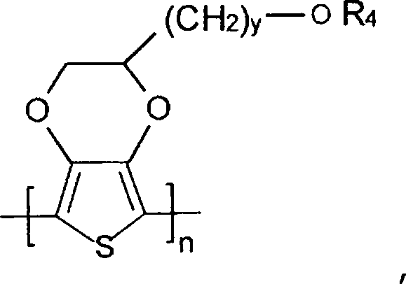
R4 Wasserstoff oder eine Alkylgruppe ist. Besondere Beispiele für solche Polymere sind hydroxyethyliertes Poly(3,4-ethylendioxythiophen) (y = 2 und R4 = H) und hydroxymethyliertes Poly(3,4-ethylendioxythiophen) (y = 1 und R4 = H).In certain embodiments, q = 0 such that the poly (3,4-ethylenedioxythiophene) is unsubstituted. However, in other embodiments, q = 1 to 2, and in some embodiments = 1, so that the polymer is substituted. For example, the polymer may be an alkyl-substituted poly (3,4-ethylenedioxythiophene) having the following general structure:
n is as defined above;
y = 1 to 10, in some
R is: a linear or branched, optionally substituted C 1 to C 18 alkyl radical (for example methyl, ethyl, n-propyl or isopropyl, n-, iso-, sec- or tert-butyl, n-pentyl , 1-methylbutyl, 2-methylbutyl, 3-methylbutyl, 1-ethylpropyl, 1,1-dimethylpropyl, 1,2-dimethylpropyl, 2,2-dimethylpropyl, n-hexyl, n-heptyl, n-octyl, 2-ethylhexyl , n-nonyl, n-decyl, n-undecyl, n-dodecyl, n-tridecyl, n-tetradecyl, n-hexadecyl, n-octadecyl, etc.); an optionally substituted C 5 to C 12 cycloalkyl group (e.g., cyclopentyl, cyclohexyl, cycloheptyl, cyclooctyl, cyclononyl, cyclodecyl, etc.); an optionally substituted C 5 to C 14 aryl radical (eg, phenyl, naphthyl, etc.); an optionally substituted C 7 to C 18 aralkyl radical (eg, benzyl, o-, m-, p-tolyl, 2,3-, 2,4-, 2,5-, 2,6, 3,4 -, 3,5-xylyl, mesityl, etc.); an optionally substituted C 1 to C 4 hydroxyalkyl radical, a hydroxy radical or a combination thereof. Examples of substituents for the radicals "R" are, for example, hydroxy, alkyl, cycloalkyl, aryl, aralkyl, alkoxy, halogen, ether, thioether, disulfide, sulfoxide, sulfone, sulfonate, amino, aldehyde, keto, carboxylic acid ester, carboxylic acid, carbonate, Carboxylate, cyano, alkylsilane and alkoxysilane groups, carboxylamide groups, etc. For example, the alkyl-substituted poly (3,4-ethylenedioxythiophene) may have the following general structure:
R 4 is hydrogen or an alkyl group. Specific examples of such polymers are hydroxyethylated poly (3,4-ethylenedioxythiophene) (y = 2 and R 4 = H) and hydroxymethylated poly (3,4-ethylenedioxythiophene) (y = 1 and R 4 = H).
Zur Bildung des leitfähigen Polymers kann eine Vielzahl von Techniken eingesetzt werden. In einer Ausführungsform können Vorläufermonomere zum Beispiel auf dem Metallsubstrat polymerisiert werden. Eine geeignete Art von Monomer zur Bildung des Polymers umfasst zum Beispiel solche mit der folgenden allgemeinen Struktur: 
T, D, R7 und q wie oben definiert sind. Besonders gut geeignete Thiophenmonomere sind gegebenenfalls substituierte 3,4-Alkylendioxythiophene mit der allgemeinen Struktur: 
T, D, R 7 and q are as defined above. Particularly suitable thiophene monomers are optionally substituted 3,4-alkylenedioxythiophenes having the general structure:
Vorläufermonomere, wie sie oben beschrieben sind, können mit Hilfe einer Vielzahl von Techniken auf dem Metallsubstrat polymerisiert werden. In einer Ausführungsform zum Beispiel wird ein Vorläufermonomer auf dem Metallsubstrat in Gegenwart eines oxidativen Katalysators chemisch polymerisiert. Der während der chemischen Polymerisation eingesetzte oxidative Katalysator umfasst etwa ein Übergangsmetallkation, wie Eisen(III)-, Kupfer(II)-, Chrom(VI)-, Cer(IV)-, Mangan(IV)-, Mangan(VII)-, Ruthenium(III)-Kation usw. Es kann auch ein Dotierungsmittel eingesetzt werden, um dem leitfähigen Polymer überschüssige Ladung zu verleihen und die Leitfähigkeit des Polymers zu stabilisieren. Das Dotierungsmittel umfasst typischerweise ein anorganisches oder organisches Anion, wie ein Ion einer Sulfonsäure. In bestimmten Ausführungsformen weist der in der Vorläuferlösung eingesetzte oxidative Katalysator insofern sowohl eine katalytische als auch eine dotierende Funktionalität auf, als er ein Kation (z. B. Übergangsmetall) und ein Anion (z. B. Sulfonsäure) enthält. Der oxidative Katalysator kann zum Beispiel ein Übergangsmetallsalz sein, das Eisen(III)-Kationen enthält, wie Eisen(III)-Halogenide (z. B. FeCl3) oder Eisen(III)-Salze anderer anorganischer Säuren, wie Fe(ClO4)3 oder Fe2(SO4)3, und die Eisen(III)-Salze organischer Säuren und anorganischer Säuren, die organische Reste umfassen. Beispiele für Eisen(III)-Salze von anorganischen Säuren mit organischen Resten sind zum Beispiel Eisen(III)-Salze von Schwefelsäuremonoestern von C1- bis C20-Alkanolen (z. B. das Eisen(III)-Salz von Laurylsulfat). Ebenso sind Beispiele für Eisen(III)-Salze von organischen Säuren zum Beispiel Eisen(III)-Salze von C1- bis C20-Alkansulfonsäuren (z. B. Methan-, Ethan-, Propan-, Butan- oder Dodecansulfonsäure); Eisen(III)-Salze von aliphatischen Perfluorsulfonsäuren (z. B. Trifluormethansulfonsäure, Perfluorbutansulfonsäure oder Perfluoroctansulfonsäure); Eisen(III)-Salze von aliphatischen C1- bis C20-Carbonsäuren (z. B. 2-Ethylhexylcarbonsäure); Eisen(III)-Salze von aliphatischen Perfluorcarbonsäuren (z. B. Trifluoressigsäure oder Perfluoroctansäure); Eisen(III)-Salze von aromatischen Sulfonsäuren, die gegebenenfalls mit C1- bis C20-Alkylgruppen substituiert sind (z. B. Benzolsulfonsäure, o-Toluolsulfonsäure, p-Toluolsulfonsäure oder Dodecylbenzolsulfonsäure); Eisen(III)-Salze von Cycloalkansulfonsäuren (z. B. Camphersulfonsäure); usw. Gemische dieser oben genannten Eisen(III)-Salze können ebenfalls verwendet werden. Eisen(III)-p-toluolsulfonat, Eisen(III)-o-toluolsulfonat und Gemische davon sind besonders gut geeignet. Ein kommerziell geeignetes Beispiel für Eisen(III)-p-toluolsulfonat ist von der H. C. Starck unter der Bezeichnung CleviosTM C erhältlich.Precursor monomers as described above can be polymerized on the metal substrate by a variety of techniques. For example, in one embodiment, a precursor monomer is chemically polymerized on the metal substrate in the presence of an oxidative catalyst. The oxidative catalyst used during the chemical polymerization includes, for example, a transition metal cation such as ferric, cupric, chromic, ceric, manganese, manganese, Ruthenium (III) cation, etc. A dopant may also be employed to impart excess charge to the conductive polymer and to stabilize the conductivity of the polymer. The dopant typically comprises an inorganic or organic anion, such as an ion of a sulfonic acid. In certain embodiments, the oxidative catalyst employed in the precursor solution has both catalytic and doping functionality in that it contains a cation (eg, transition metal) and an anion (eg, sulfonic acid). The oxidative catalyst may be, for example, a transition metal salt containing iron (III) cations, such as ferric halides (eg, FeCl 3 ) or iron (III) salts of other inorganic acids, such as Fe (ClO 4 ) 3 or Fe 2 (SO 4 ) 3 , and the ferric salts of organic acids and inorganic acids comprising organic radicals. Examples of iron (III) salts of inorganic acids with organic radicals are, for example, iron (III) salts of sulfuric acid monoesters of C 1 to C 20 alkanols (for example the iron (III) salt of lauryl sulfate). Likewise, examples of iron (III) salts of organic acids are, for example, iron (III) salts of C 1 to C 20 alkanesulfonic acids (eg methane, ethane, propane, butane or dodecane sulfonic acid); Iron (III) salts of aliphatic perfluorosulfonic acids (eg trifluoromethanesulfonic acid, perfluorobutanesulfonic acid or perfluorooctanesulfonic acid); Iron (III) salts of aliphatic C 1 to C 20 carboxylic acids (eg 2-ethylhexylcarboxylic acid); Ferric salts of aliphatic perfluorocarboxylic acids (eg, trifluoroacetic acid or perfluorooctanoic acid); Ferric salts of aromatic sulfonic acids optionally substituted with C 1 to C 20 alkyl groups (for example, benzenesulfonic acid, o-toluenesulfonic acid, p-toluenesulfonic acid or dodecylbenzenesulfonic acid); Ferric salts of cycloalkanesulfonic acids (eg, camphorsulfonic acid); etc. Mixtures of these above-mentioned ferric salts may also be used. Iron (III) p-toluenesulfonate, iron (III) o-toluenesulfonate and mixtures thereof are particularly well suited. A commercially suitable example of iron (III) p-toluenesulfonate is available from HC Starck under the name Clevios ™ C.
Verschiedene Verfahren können verwendet werden, um die leitfähige Beschichtung auf dem Metallsubstrat zu bilden. In einer Ausführungsform werden der oxidative Katalysator und das Monomer entweder nacheinander oder zusammen aufgetragen, so dass die Polymerisationsreaktion in situ auf dem Teil stattfindet. Zu den geeigneten Auftragstechniken gehören Siebdruck, Tauchbeschichtung, elektrophoretische Beschichtung und Sprühbeschichtung; sie können verwendet werden, um eine leitfähige Polymerbeschichtung zu bilden. Als Beispiel kann das Monomer zunächst unter Bildung einer Vorläuferlösung mit dem oxidativen Katalysator gemischt werden. Sobald das Gemisch gebildet ist, kann es aufgetragen und polymerisieren gelassen werden, so dass die leitfähige Beschichtung auf der Oberfläche entsteht. Alternativ dazu können der oxidative Katalysator und das Monomer auch nacheinander aufgetragen werden. In einer Ausführungsform wird der oxidative Katalysator zum Beispiel in einem organischen Lösungsmittel (z. B. Butanol) gelöst und dann als Tauchlösung aufgetragen. Das Substrat kann dann getrocknet werden, um das Lösungsmittel davon zu entfernen. Danach kann das Substrat in eine Lösung, die die Monomere enthält, eingetaucht werden. Die Polymerisation wird typischerweise je nach dem verwendeten Oxidationsmittel und der gewünschten Reaktionszeit bei Temperaturen von etwa –10°C bis etwa 250°C und in einigen Ausführungsformen etwa 0°C bis etwa 200°C durchgeführt. Geeignete Polymerisationstechniken, wie sie oben beschrieben sind, sind ausführlicher in der
Während in bestimmten Ausführungsformen chemische Polymerisationstechniken eingesetzt werden können, möchte man häufig die Verwendung von oxidativen Katalysatoren in dem Kondensator minimieren, da solche Stoffe häufig zur Bildung von Eisenradikalen (z. B. Fe2+- oder Fe3+-Ionen) führen können. Diese Radikale können wiederum zum dielektrischen Abbau der hohen Spannungen führen, die während der Verwendung des Flüssigkeitskondensators häufig eingesetzt werden. In bestimmten Ausführungsformen können also anodische elektrochemische Polymerisationstechniken eingesetzt werden, um das Polymer zu bilden. Bei solchen Techniken wird im Allgemeinen eine kolloidale Suspension eingesetzt, die im Wesentlichen frei von oxidativen Katalysatoren auf Eisenbasis ist. Zum Beispiel enthält die kolloidale Suspension typischerweise weniger als etwa 0,5 Gew.-%, in einigen Ausführungsformen weniger als etwa 0,1 Gew.-% und in einigen Ausführungsformen weniger als etwa 0,05 Gew.-% (z. B. 0 Gew.-%) solcher oxidativer Katalysatoren auf Eisenbasis. While chemical polymerization techniques may be used in certain embodiments, it is often desirable to minimize the use of oxidative catalysts in the capacitor since such materials can often lead to the formation of iron radicals (eg, Fe 2+ or Fe 3+ ions). These radicals, in turn, can lead to the dielectric degradation of the high voltages that are commonly used during the use of the liquid condenser. Thus, in certain embodiments, anodic electrochemical polymerization techniques can be used to form the polymer. Such techniques generally employ a colloidal suspension that is substantially free of iron-based oxidative catalysts. For example, the colloidal suspension typically contains less than about 0.5 weight percent, in some embodiments less than about 0.1 weight percent, and in some embodiments less than about 0.05 weight percent (e.g. 0% by weight) of such oxidative iron-based catalysts.
Die kolloidale Suspension kann je nach der besonderen Art der Komponenten der Suspension in Form einer Makroemulsion, Mikroemulsion, Lösung usw. vorliegen. Unabhängig davon enthält die Suspension im Allgemeinen ein Lösungsmittel, das als kontinuierliche Phase dient, in der das Vorläufermonomer dispergiert ist. In der kolloidalen Suspension kann eine Vielzahl verschiedener Lösungsmittel, wie Alkohole, Glycole, Wasser usw., eingesetzt werden. In einer besonderen Ausführungsform ist die kolloidale Suspension eine wässrige Suspension. Lösungsmittel (z. B. Wasser) können etwa 50 Gew.-% bis etwa 99 Gew.-%, in einigen Ausführungsformen etwa 70 Gew.-% bis etwa 98 Gew.-% und in einigen Ausführungsformen etwa 80 Gew.-% bis etwa 95 Gew.-% bilden. Die übrigen Komponenten der kolloidalen Suspension (z. B. Vorläufermonomere, Tenside und Sulfonsäuren) können ebenso etwa 1 Gew.-% bis etwa 50 Gew.-%, in einigen Ausführungsformen etwa 2 Gew.-% bis etwa 30 Gew.-% und in einigen Ausführungsformen etwa 5 Gew.-% bis etwa 20 Gew.-% der kolloidalen Suspension ausmachen.The colloidal suspension may be in the form of a macroemulsion, microemulsion, solution, etc., depending on the particular nature of the components of the suspension. Regardless, the suspension generally contains a solvent which serves as a continuous phase in which the precursor monomer is dispersed. In the colloidal suspension, a variety of different solvents, such as alcohols, glycols, water, etc., can be used. In a particular embodiment, the colloidal suspension is an aqueous suspension. Solvents (eg, water) may be about 50% to about 99% by weight, in some embodiments about 70% to about 98%, and in some embodiments about 80% to about form about 95 wt .-%. The remaining components of the colloidal suspension (e.g., precursor monomers, surfactants and sulfonic acids) may also be from about 1% to about 50% by weight, in some embodiments from about 2% to about 30% by weight, and in some embodiments, from about 5% to about 20% by weight of the colloidal suspension.
In der kolloidalen Suspension kann ein Tensid eingesetzt werden, um Mizellen zu bilden, die zu einer Erhöhung der Löslichkeit führen, wobei eine makroskopisch oder mikroskopisch homogene Verteilung dieser Mizellen und des Vorläufermonomers entsteht. Das Tensid kann ionisch (z. B. anionisch, kationisch oder zwitterionisch) oder nichtionisch sein. Das ionische Tensid kann zum Beispiel ein anionisches Tensid sein, wie ein Sulfonat (z. B. Alkylarylensulfonate, α-Olefinsulfonate, β-Alkoxyalkansulfonate, Alkyllaurylsulfonate, Alkylmonoglyceridsulfonate, Alkylethersulfonate usw.), Sulfat (z. B. Alkylsulfate, Alkylarylsulfate, Alkylethersulfate, Alkylmonoglyceridsulfate usw.), Sulfosuccinat, Sarcosinat usw. sowie Derivate, Salze, Polymere und/oder Gemische der obigen. Besondere Beispiele für ionische Tenside sind unter Anderem C8-C30-Alkylsulfate, C8-C30-Alkylethersulfate, die ein oder zwei mol Ethoxylierung aufweisen, C8-C30-Alkoylsarcosinate, C8-C30-Sulfoacetate, C8-C30-Sulfosuccinate, C8-C30-Alkyldiphenyloxiddisulfonate, C8-C30-Alkylcarbonate, C8-C30-Arylensulfonate usw. Die C8-C30-Alkylgruppe kann geradkettig (z. B. Dodecyl) oder verzweigt (z. B. 2-Ethylhexyl) sein. Das Kation des ionischen Tensids kann ein Proton, Alkalimetall (z. B. Natrium oder Kalium), Ammonium, C1-C4-Alkylammonium (z. B. Mono-, Di-, Tri-) oder C1-C3-Alkanolammonium (z. B. Mono-, Di-, Tri-) sein. In einer besonderen Ausführungsform kann das anionische Tensid zum Beispiel ein Alkylbenzolsulfonat mit der folgenden allgemeinen Struktur sein: 
R1 eine Alkylgruppe mit 8 bis 30 Kohlenstoffatomen, in einigen Ausführungsformen 9 bis 20 und in einigen Ausführungsformen 10 bis 14 (z. B. 12) Kohlenstoffatomen ist; und
M ein Kation, wie Wasserstoff, ein Metall (z. B. Natrium, Kalium, Lithium usw.), Ammonium (NH4 +) usw., ist. Vergleichbare Verbindungen mit einem Naphthalinkern können ebenfalls verwendet werden, um Alkylnaphthalinsulfonate zu bilden. Ohne uns auf eine bestimmte Theorie festlegen zu wollen, glauben wir, dass solche Alkylarylensulfonate besonders effektiv bezüglich der Erhöhung der Flächenbedeckung der kolloidalen Suspension auf dem Substrat sind, während sie auch den Ladungstransport erleichtern.In the colloidal suspension, a surfactant can be used to form micelles that result in an increase in solubility, resulting in a macroscopically or microscopically homogeneous distribution of these micelles and the precursor monomer. The surfactant may be ionic (eg anionic, cationic or zwitterionic) or nonionic. The ionic surfactant may be, for example, an anionic surfactant such as a sulfonate (e.g., alkylarylene sulfonates, α-olefin sulfonates, β-alkoxyalkanesulfonates, alkyl lauryl sulfonates, alkyl monoglyceride sulfonates, alkyl ether sulfonates, etc.), sulfate (e.g., alkyl sulfates, alkylaryl sulfates, alkyl ether sulfates, Alkyl monoglyceride sulfates, etc.), sulfosuccinate, sarcosinate, etc. as well as derivatives, salts, polymers and / or mixtures of the above. Specific examples of ionic surfactants include C 8 -C 30 alkyl sulfates, C 8 -C 30 alkyl ether sulfates having one or two moles of ethoxylation, C 8 -C 30 alkoxy sarcosinates, C 8 -C 30 sulfoacetates, C 8 -C 30 sulfosuccinates, C 8 -C 30 alkyl diphenyl oxide disulfonates, C 8 -C 30 alkyl carbonates, C 8 -C 30 arylene sulfonates, etc. The C 8 -C 30 alkyl group may be straight chain (eg, dodecyl) or branched (eg, 2-ethylhexyl). The cation of the ionic surfactant may be a proton, alkali metal (eg sodium or potassium), ammonium, C 1 -C 4 -alkylammonium (eg mono-, di-, tri-) or C 1 -C 3 - Alkanolammonium (eg mono-, di-, tri-). In a particular embodiment, the anionic surfactant may be, for example, an alkylbenzenesulfonate having the following general structure:
R 1 is an alkyl group of 8 to 30 carbon atoms, in some embodiments 9 to 20 and in some embodiments 10 to 14 (e.g., 12) carbon atoms; and
M is a cation such as hydrogen, a metal (e.g., sodium, potassium, lithium, etc.), ammonium (NH 4 + ), etc. Comparable compounds having a naphthalene nucleus may also be used to form alkylnaphthalenesulfonates. Without wishing to be bound by any particular theory, we believe that such alkylarylene sulfonates are particularly effective in increasing the area coverage of the colloidal suspension on the substrate, while also facilitating charge transport.
Selbstverständlich können neben oder anstelle eines anionischen Tensids auch kationische Tenside und/oder zwitterionische Tenside eingesetzt werden. Beispiele für kationische Tenside sind etwa Aminosäuren, Alkylaminsalze, quartäre Ammoniumsalze, Pyridiniumsalze usw. Zum Beispiel sind geeignete Alkylaminsalze etwa Salze von primären oder sekundären Aminen mit 3 bis 22 Kohlenstoffatomen und einer Carbonsäure mit 1 bis 22 Kohlenstoffatomen oder einer anorganischen Mineralsäure, wie Dodecylamin-Acetatsalz, Dodecylamin-Hydrochloridsalz, Dodecylamin-Stearatsalz, Dodecylaminsulfonat, Dimethylamin-Stearatsalz usw. In bestimmten Ausführungsformen können solche kationischen Tenside in situ innerhalb der kolloidalen Suspension durch Zugabe eines Amins (z. B. Dodecylamin) und einer Säure, wie der im Folgenden beschriebenen Sulfonsäure (z. B. Toluolsulfonsäure), gebildet werden.Of course, it is also possible to use cationic surfactants and / or zwitterionic surfactants in addition to or instead of an anionic surfactant. Examples of cationic surfactants include amino acids, alkylamine salts, quaternary ammonium salts, pyridinium salts, etc. For example, suitable alkylamine salts salts of primary or secondary amines having 3 to 22 carbon atoms and a carboxylic acid having 1 to 22 carbon atoms or an inorganic mineral acid such as dodecylamine acetate salt, dodecylamine hydrochloride salt, dodecylamine stearate salt, dodecylamine sulfonate, dimethylamine stearate salt, etc. In certain embodiments, such cationic surfactants are formed in situ within the colloidal suspension by addition of an amine (e.g., dodecylamine) and an acid such as the sulfonic acid (eg, toluenesulfonic acid) described below.
Nichtionische Tenside können ebenfalls eingesetzt werden. Solche Tenside weisen typischerweise eine hydrophobe Base, wie eine langkettige Alkylgruppe oder eine alkylierte Arylgruppe, und eine hydrophile Kette, die eine bestimmte Anzahl (z. B. 1 bis etwa 30) an Ethoxy- und/oder Propoxy-Struktureinheiten enthält, auf. Obwohl es nicht unbedingt notwendig ist, können nichtionische Tenside, die einen bestimmten Hydrophilen/Lipophilen-Gleichgewichtswert (”HLB”) aufweisen, dazu beitragen, die Stabilität der kolloidalen Suspension zu verbessern. Der HLB-Index ist in der Technik wohlbekannt und ist eine Skala, die das Gleichgewicht zwischen den hydrophilen und lipophilen Lösungstendenzen einer Verbindung misst, wobei kleinere Zahlen für hochgradig lipophile Tendenzen stehen und die höheren Zahlen für hochgradig hydrophile Tendenzen stehen. In einigen Ausführungsformen der vorliegenden Erfindung beträgt der HLB-Wert des nichtionischen Tensids etwa 5 bis etwa 20, in einigen Ausführungsformen etwa 10 bis etwa 19 und in einigen Ausführungsformen etwa 11 bis etwa 18. Falls gewünscht, können zwei oder mehr Tenside eingesetzt werden, die HLB-Werte entweder unterhalb oder oberhalb des gewünschten Werts aufweisen, aber zusammen einen durchschnittlichen HLB-Wert innerhalb des gewünschten Bereichs aufweisen.Nonionic surfactants can also be used. Such surfactants typically have a hydrophobic base such as a long chain alkyl group or an alkylated aryl group, and a hydrophilic chain containing a certain number (e.g., 1 to about 30) of ethoxy and / or propoxy moieties. Although not strictly necessary, nonionic surfactants having a particular hydrophilic / lipophilic balance value ("HLB") may help to improve the stability of the colloidal suspension. The HLB index is well known in the art and is a scale that measures the balance between the hydrophilic and lipophilic dissolution tendencies of a compound, with smaller numbers indicating highly lipophilic tendencies and the higher numbers being highly hydrophilic tendencies. In some embodiments of the present invention, the HLB of the nonionic surfactant is from about 5 to about 20, in some embodiments from about 10 to about 19, and in some embodiments from about 11 to about 18. If desired, two or more surfactants can be used HLB values either below or above the desired value, but together have an average HLB value within the desired range.
Zu den geeigneten nichtionischen Tensiden gehören zum Beispiel etwa Polyoxyethylen-Ketten als hydrophile Gruppen, Polyglycerinfettsäureester, Polyglycerinfettalkoholether, Saccharosefettsäureester und Hydrocarbylpolyglycoside. In einer Ausführungsform umfasst das nichtionische Tensid Polyoxyethylen-Ketten als hydrophile Gruppen und ist aus der Gruppe ausgewählt, die aus Polyoxyethylenfettsäureestern, Polyoxyethylenfettalkoholethern, Polyoxyethylensorbitolanhydridfettsäureestern, Polyoxyethylenglycerinmonofettsäureestern, Polyoxyethylen-hydriertem-Ricinusöl und Polyoxyethylen-hydriertes-Ricinusölmonofettsäureestern usw. sowie Kombinationen davon besteht. Besonders gut geeignet sind Polyoxyethylenfettalkoholether, bei denen der Fettalkohol, der den Polyoxyethylenfettalkoholether bildet, gesättigt oder ungesättigt ist und 8 bis 22 Kohlenstoffatome (z. B. 8 bis 14) aufweist und die Polyoxyethylen-Struktureinheit im Durchschnitt 4 bis 60 Ethylenoxid-Repetiereinheiten (z. B. 4 bis 12) aufweist. Beispiele für solche Tenside sind Polyoxyethylenoctylether (z. B. Polyoxyethylen-5-octylether), Polyoxyethylendecylether, Polyoxyethylenlaurylether (z. B. Polyoxyethylen-8-laurylether oder Polyoxyethylen-10-laurylether), Polyoxyethylenmyristylether, Polyoxyethylenpalmitylether, Polyoxyethylenisostearylether, Polyoxyethylenstearylether, Polyoxyethylenoleylether, Polyoxyethylenbehenylether usw.Suitable nonionic surfactants include, for example, polyoxyethylene chains as hydrophilic groups, polyglycerol fatty acid esters, polyglycerol fatty alcohol ethers, sucrose fatty acid esters, and hydrocarbyl polyglycosides. In one embodiment, the nonionic surfactant comprises polyoxyethylene chains as hydrophilic groups and is selected from the group consisting of polyoxyethylene fatty acid esters, polyoxyethylene fatty alcohol ethers, polyoxyethylene sorbitol anhydride fatty acid esters, polyoxyethylene glycerol monofatty acid esters, polyoxyethylene hydrogenated castor oil and polyoxyethylene hydrogenated castor mono-fatty acid esters, etc., and combinations thereof. Particularly useful are polyoxyethylene fatty alcohol ethers in which the fatty alcohol forming the polyoxyethylene fatty alcohol ether is saturated or unsaturated and has 8 to 22 carbon atoms (eg, 8 to 14) and the polyoxyethylene moiety has on average from 4 to 60 repeating ethylene oxide units (e.g. B. 4 to 12). Examples of such surfactants are polyoxyethylene octyl ethers (e.g., polyoxyethylene-5-octyl ether), polyoxyethylene decyl ether, polyoxyethylene lauryl ether (e.g., polyoxyethylene-8-lauryl ether or polyoxyethylene 10-lauryl ether), polyoxyethylene myristyl ether, polyoxyethylene palmitate ether, polyoxyethylene isostearyl ether, polyoxyethylene stearyl ether, polyoxyethylene oleyl ether, polyoxyethylene behenyl ether etc.
Unabhängig von seiner besonderen Form kann das Tensid die Bildung einer kolloidalen Suspension von Monomertröpfchen erleichtern. Ohne uns auf eine bestimmte Theorie festlegen zu wollen, glauben wir, dass solche Tröpfchen zur Bildung von relativ kleinen Polymereinheiten auf der Oberfläche des Kathodensubstrats während der anodischen elektrochemischen Polymerisation führen können. Solche kleineren Polymereinheiten können wiederum zu einer Beschichtung führen, die im Wesentlichen gleichmäßig mit ausgezeichneter Flächenbedeckung ist. Die Größe der Tröpfchen hängt zum Teil von der Art der Suspension ab. ”Mikroemulsionen” können zum Beispiel Tröpfchen enthalten, die einen mittleren Durchmesser von etwa 5 Mikrometer oder weniger, in einigen Ausführungsformen etwa 4 Mikrometer oder weniger, in einigen Ausführungsformen etwa 10 Nanometer bis etwa 2 Mikrometer und in einigen Ausführungsformen etwa 20 Nanometer bis etwa 1 Mikrometer aufweisen. ”Makroemulsionen” können ebenfalls Tröpfchen enthalten, die eine Größe von etwa 5 bis etwa 100 Mikrometer und in einigen Ausführungsformen etwa 10 bis etwa 80 Mikrometer aufweisen. Der Ausdruck ”Durchmesser” kann sich auf den ”hydrodynamischen Äquivalenzdurchmesser” eines Teilchens beziehen, wie er mit Hilfe bekannter Techniken, wie Photonenkorrelationsspektroskopie, dynamischer Lichtstreuung, quasielastischer Lichtstreuung usw. bestimmt wird. Diese Verfahren beruhen im Allgemeinen auf der Korrelation der Teilchengröße mit Diffusionseigenschaften von Teilchen, die aus Messungen der Brownschen Bewegung erhalten werden. Die Brownsche Bewegung ist die statistische Bewegung der Teilchen aufgrund der Stöße durch die Lösungsmittelmoleküle, die die Teilchen umgeben. Je größer das Teilchen, desto langsamer ist die Brownsche Bewegung. Die Geschwindigkeit ist durch den translationalen Diffusionskoeffizienten definiert. Der gemessene Teilchengrößewert bezieht sich also darauf, wie sich das Teilchen innerhalb einer Flüssigkeit bewegt und wird der ”hydrodynamische Durchmesser” genannt. Verschiedene Teilchengröße-Analysegeräte können eingesetzt werden, um den Durchmesser in dieser Weise zu messen. Ein besonderes Beispiel ist ein Cordouan VASCO 3 Particle Size Analyzer.Regardless of its particular form, the surfactant may facilitate the formation of a colloidal suspension of monomer droplets. Without wishing to be bound by any particular theory, we believe that such droplets may result in the formation of relatively small polymer units on the surface of the cathode substrate during anodic electrochemical polymerization. Such smaller polymer units may in turn result in a coating that is substantially uniform with excellent area coverage. The size of the droplets depends in part on the type of suspension. For example, "microemulsions" may include droplets having a mean diameter of about 5 microns or less, in some embodiments about 4 microns or less, in some embodiments about 10 nanometers to about 2 microns, and in some embodiments about 20 nanometers to about 1 micron exhibit. "Macroemulsions" may also contain droplets having a size of about 5 to about 100 microns, and in some embodiments about 10 to about 80 microns. The term "diameter" may refer to the "hydrodynamic equivalent diameter" of a particle as determined by known techniques such as photon correlation spectroscopy, dynamic light scattering, quasi-elastic light scattering, etc. These methods generally rely on the correlation of particle size with diffusion properties of particles obtained from Brownian motion measurements. The Brownian motion is the statistical motion of the particles due to the collisions of the solvent molecules surrounding the particles. The larger the particle, the slower the Brownian motion. The velocity is defined by the translational diffusion coefficient. The measured particle size value thus refers to how the particle moves within a liquid and is called the "hydrodynamic diameter". Various particle size analyzers can be used to measure the diameter in this way. A particular example is a Cordouan VASCO 3 Particle Size Analyzer.
Um dazu beizutragen, die gewünschte Verbesserung der Flächenbedeckung zu erreichen, ist es auch im Allgemeinen erwünscht, dass die Konzentration des Tensids selektiv innerhalb eines bestimmten Bereichs relativ zu den Vorläufermonomeren gesteuert wird. Zum Beispiel kann das Verhältnis des Gewichts von Tensiden zu dem Gewicht von Vorläufermonomeren innerhalb der kolloidalen Suspension etwa 0,5 bis etwa 1,5, in einigen Ausführungsformen etwa 0,6 bis etwa 1,4 und in einigen Ausführungsformen etwa 0,8 bis etwa 1,2 betragen. Tenside können zum Beispiel etwa 0,2 Gew.-% bis etwa 10 Gew.-%, in einigen Ausführungsformen etwa 0,5 Gew.-% bis etwa 8 Gew.-% und in einigen Ausführungsformen etwa 1 Gew.-% bis etwa 5 Gew.-% der kolloidalen Suspension ausmachen. Die Gesamtkonzentration der in der kolloidalen Suspension eingesetzten Monomere kann auch etwa 0,1 Gew.-% bis etwa 15 Gew.-%, in einigen Ausführungsformen etwa 0,4 Gew.-% bis etwa 10 Gew.-% und in einigen Ausführungsformen etwa 0,5 Gew.-% bis etwa 5 Gew.-% der kolloidalen Suspension betragen. In order to help achieve the desired area coverage improvement, it is also generally desirable that the concentration of the surfactant be selectively controlled within a certain range relative to the precursor monomers. For example, the ratio of the weight of surfactants to the weight of precursor monomers within the colloidal suspension may be from about 0.5 to about 1.5, in some embodiments from about 0.6 to about 1.4, and in some embodiments from about 0.8 to about 1.2 amount. Surfactants may, for example, be from about 0.2% to about 10% by weight, in some embodiments from about 0.5% to about 8% by weight, and in some embodiments from about 1% to about 5% by weight of the colloidal suspension. The total concentration of monomers employed in the colloidal suspension may also be from about 0.1% to about 15% by weight, in some embodiments from about 0.4% to about 10% by weight, and in some embodiments about From 0.5% to about 5% by weight of the colloidal suspension.
Die kolloidale Suspension kann auch eine Sulfonsäure enthalten, die als sekundäres Dotierungsmittel wirken kann, um das leitfähige Polymer mit überschüssiger Ladung zu versehen und seine Leitfähigkeit zu stabilisieren. Solche Säuren können zum Beispiel zu einer kolloidalen Suspension führen, die eine elektrische Leitfähigkeit von etwa 1 bis etwa 100 Millisiemens pro Zentimeter (”mS/cm”), in einigen Ausführungsformen etwa 5 bis etwa 60 mS/cm und in einigen Ausführungsformen etwa 15 bis etwa 50 mS/cm aufweist, bestimmt bei einer Temperatur von 23°C unter Verwendung irgendeines bekannten Messgeräts für die elektrische Leitfähigkeit (z. B. Oakton Con Series 11). Die Art der Sulfonsäure sowie ihre relative Konzentration kann ebenfalls gezielt gesteuert werden, so dass der pH-Wert der kolloidalen Suspension im Bereich von etwa 0,2 bis etwa 8,5, in einigen Ausführungsformen etwa 3,0 bis etwa 8,0 und in einigen Ausführungsformen etwa 5,0 bis etwa 7,5 liegt. Zum Beispiel beträgt das Verhältnis des Gewichts von Sulfonsäuren zu dem Gewicht von Vorläufermonomeren innerhalb der kolloidalen Suspension etwa 0,2 bis etwa 1,2, in einigen Ausführungsformen etwa 0,4 bis etwa 1,1 und in einigen Ausführungsformen etwa 0,6 bis etwa 1,0. Ebenso beträgt das Verhältnis des Gewichts von Sulfonsäuren zu dem Gewicht von Tensiden innerhalb der kolloidalen Suspension etwa 0,2 bis etwa 1,2, in einigen Ausführungsformen etwa 0,3 bis etwa 0,9 und in einigen Ausführungsformen etwa 0,4 bis etwa 0,8.The colloidal suspension may also contain a sulfonic acid which may act as a secondary dopant to provide the conductive polymer with excess charge and to stabilize its conductivity. Such acids may, for example, result in a colloidal suspension having an electrical conductivity of from about 1 to about 100 millisiemens per centimeter ("mS / cm"), in some embodiments from about 5 to about 60 mS / cm, and in some embodiments about 15 to about 50 mS / cm, determined at a temperature of 23 ° C using any known electrical conductivity meter (e.g., Oakton Con Series 11). The type of sulfonic acid and its relative concentration can also be controlled selectively so that the pH of the colloidal suspension ranges from about 0.2 to about 8.5, in some embodiments from about 3.0 to about 8.0, and in In some embodiments, about 5.0 to about 7.5. For example, the ratio of the weight of sulfonic acids to the weight of precursor monomers within the colloidal suspension is from about 0.2 to about 1.2, in some embodiments from about 0.4 to about 1.1, and in some embodiments from about 0.6 to about 1.0. Also, the ratio of the weight of sulfonic acids to the weight of surfactants within the colloidal suspension is from about 0.2 to about 1.2, in some embodiments from about 0.3 to about 0.9, and in some embodiments from about 0.4 to about 0 ,8th.
Die Sulfonsäure ist typischerweise eine niedermolekulare Monosulfonsäure, Disulfonsäure oder Trisulfonsäure auf organischer Basis. Spezielle Beispiele für solche Säuren sind zum Beispiel Alkylsulfonsäuren (z. B. 2-Acrylamid-2-methylpropansulfonsäure usw.); Arylensulfonsäuren, wie Benzolsulfonsäuren (z. B. Phenolsulfonsäure, Styrolsulfonsäure, p-Toluolsulfonsäure, Dodecylbenzolsulfonsäure usw.) und Naphthalinsulfonsäuren (z. B. 1-Naphthalinsulfonsäure, 2-Naphthalinsulfonsäure, 1,3-Naphthalindisulfonsäure, 1,3,6-Naphthalintrisulfonsäure, 6-Ethyl-1-naphthalinsulfonsäure usw.); Anthrachinonsulfonsäuren (z. B. Anthrachinon-1-sulfonsäure, Anthrachinon-2-sulfonsäure, Anthrachinon-2,6-disulfonsäure, 2-Methylanthrachinon-6-sulfonsäure usw.); Camphersulfonsäuren sowie Derivate und Gemische davon. Arylensulfonsäuren sind für die Verwendung in der kolloidalen Suspension besonders gut geeignet, wie 1-Naphthalinsulfonsäure, 2-Naphthalinsulfonsäure und/oder p-Toluolsulfonsäure. Man sollte sich darüber im Klaren sein, dass der hier verwendete Ausdruck ”Sulfonsäure” auch Salze von Säuren, wie den oben genannten, umfasst, die in einer wässrigen Lösung dissoziieren können, wie Natriumsalze, Lithiumsalze, Kaliumsalze usw. In einer Ausführungsform zum Beispiel kann die Sulfonsäure ein Natrium- oder Kaliumsalz von 1-Naphthalinsulfonsäure, 2-Naphthalinsulfonsäure und/oder p-Toluolsulfonsäure sein.The sulfonic acid is typically a low molecular weight monosulfonic acid, disulfonic acid or trisulfonic acid on an organic basis. Specific examples of such acids are, for example, alkylsulfonic acids (e.g., 2-acrylamido-2-methylpropanesulfonic acid, etc.); Arylene sulfonic acids such as benzenesulfonic acids (eg, phenolsulfonic acid, styrenesulfonic acid, p-toluenesulfonic acid, dodecylbenzenesulfonic acid, etc.) and naphthalenesulfonic acids (eg, 1-naphthalenesulfonic acid, 2-naphthalenesulfonic acid, 1,3-naphthalenedisulfonic acid, 1,3,6-naphthalenetrisulfonic acid, 6-ethyl-1-naphthalenesulfonic acid, etc.); Anthraquinone sulfonic acids (e.g., anthraquinone-1-sulfonic acid, anthraquinone-2-sulfonic acid, anthraquinone-2,6-disulfonic acid, 2-methylanthraquinone-6-sulfonic acid, etc.); Camphorsulfonic acids and derivatives and mixtures thereof. Arylene sulfonic acids are particularly well suited for use in the colloidal suspension, such as 1-naphthalenesulfonic acid, 2-naphthalenesulfonic acid and / or p-toluenesulfonic acid. It should be understood that the term "sulfonic acid" as used herein also includes salts of acids, such as those mentioned above, that can dissociate in an aqueous solution, such as sodium salts, lithium salts, potassium salts, etc. In one embodiment, for example the sulfonic acid is a sodium or potassium salt of 1-naphthalenesulfonic acid, 2-naphthalenesulfonic acid and / or p-toluenesulfonic acid.
Neben den oben genannten Komponenten kann die kolloidale Suspension auch verschiedene andere Additive enthalten. Zum Beispiel kann in bestimmten Ausführungsformen ein Entschäumungsmittel eingesetzt werden, um den Grad der Schaumbildung durch das nichtionische Tensid während der anodischen elektrochemischen Polymerisation zu reduzieren. Geeignete Entschäumungsmittel sind zum Beispiel etwa Öle, Ester, Ether, Glycole, Polysiloxane, langkettige sauerstoffhaltige Kohlenwasserstoffe (z. B. C6- bis C12-Alkohole) usw. sowie Gemische davon. Besonders gut geeignete Entschäumungsmittel sind langkettige sauerstoffhaltige Kohlenwasserstoffe, wie Octanol, Decanol und Polyethylenglycole. Wenn solche Entschäumungsmittel eingesetzt werden, können sie etwa 0,01 Gew.-% bis etwa 5 Gew.-%, in einigen Ausführungsformen etwa 0,05 Gew.-% bis etwa 4 Gew.-% und in einigen Ausführungsformen etwa 0,1 Gew.-% bis etwa 2 Gew.-% der kolloidalen Suspension ausmachen. Neben Entschäumungsmitteln kann in der kolloidalen Suspension auch eine Vielzahl anderer Additive eingesetzt werden.In addition to the above-mentioned components, the colloidal suspension may also contain various other additives. For example, in certain embodiments, a defoaming agent may be employed to reduce the degree of foaming by the nonionic surfactant during anodic electrochemical polymerization. Suitable defoaming agents include, for example, oils, esters, ethers, glycols, polysiloxanes, long chain oxygenated hydrocarbons (e.g., C 6 to C 12 alcohols), etc., and mixtures thereof. Particularly suitable defoaming agents are long-chain oxygen-containing hydrocarbons, such as octanol, decanol and polyethylene glycols. When such defoaming agents are employed, they may be from about 0.01% to about 5% by weight, in some embodiments from about 0.05% to about 4% by weight, and in some embodiments about 0.1 From about 2% by weight to about 2% by weight of the colloidal suspension. In addition to defoaming agents can be used in the colloidal suspension, a variety of other additives.
Zum Auftragen der kolloidalen Suspension auf das Metallsubstrat kann eine Vielzahl von geeigneten Auftragungstechniken eingesetzt werden, wie Siebdruck, Tauchen, elektrophoretische Beschichtung, Sprühen usw. Unabhängig davon, wie es aufgetragen wird, kann das Monomer innerhalb der kolloidalen Suspension anodisch elektrochemisch polymerisiert werden, um auf der Oberfläche des Metallsubstrats eine leitfähige Polymerbeschichtung zu bilden. In einer Ausführungsform zum Beispiel wird das Metallsubstrat in ein Bad eingetaucht, das die kolloidale Suspension der vorliegenden Erfindung enthält. In dem Bad kann sich für die Elektrolyse ein Elektrodenpaar befinden. Eine Elektrode kann mit dem positiven Pol einer Stromquelle verbunden sein und auch in Kontakt mit dem Metallsubstrat stehen. Die andere Elektrode kann mit dem negativen Pol der Stromquelle und einem zusätzlichen inerten Metall verbunden sein. Während des Betriebs liefert die Stromquelle einen Strom zu den Elektroden in der elektrochemischen Zelle und induziert dadurch eine Elektrolyse des Elektrolyten und eine oxidative Polymerisation des Monomers in der kolloidalen Suspension oder Lösung auf das Metallsubstrat. Die anodische elektrochemische Polymerisation wird im Allgemeinen bei Umgebungstemperatur durchgeführt, um zu gewährleisten, dass die kolloidale Suspension keine Phasentrennung erfährt. Zum Beispiel kann die kolloidale Suspension bei einer Temperatur von etwa 15°C bis etwa 80°C, in einigen Ausführungsformen etwa 20°C bis etwa 75°C und in einigen Ausführungsformen etwa 25°C bis etwa 50°C gehalten werden. Die Zeitdauer, während der das Metallsubstrat während der anodischen elektrochemischen Polymerisation mit der kolloidalen Suspension in Kontakt ist, kann variieren. Zum Beispiel kann das Metallsubstrat während einer Zeit im Bereich von etwa 10 Sekunden bis etwa 10 Minuten in eine solche Lösung eingetaucht werden.For applying the colloidal suspension to the metal substrate, a variety of suitable application techniques can be employed, such as screen printing, dipping, electrophoretic coating, spraying, etc. Regardless of how it is applied, the monomer within the colloidal suspension can be anodically electrochemically polymerized to the surface of the metal substrate to form a conductive polymer coating. For example, in one embodiment, the metal substrate is immersed in a bath containing the colloidal suspension of the present invention. In the bathroom can be for the Electrolysis are a pair of electrodes. An electrode may be connected to the positive pole of a power source and also be in contact with the metal substrate. The other electrode may be connected to the negative pole of the current source and an additional inert metal. During operation, the power source supplies current to the electrodes in the electrochemical cell, thereby inducing electrolysis of the electrolyte and oxidative polymerization of the monomer in the colloidal suspension or solution onto the metal substrate. The anodic electrochemical polymerization is generally conducted at ambient temperature to ensure that the colloidal suspension does not undergo phase separation. For example, the colloidal suspension may be maintained at a temperature of from about 15 ° C to about 80 ° C, in some embodiments from about 20 ° C to about 75 ° C, and in some embodiments from about 25 ° C to about 50 ° C. The length of time the metal substrate is in contact with the colloidal suspension during anodic electrochemical polymerization may vary. For example, the metal substrate may be immersed in such a solution for a time in the range of about 10 seconds to about 10 minutes.
Unabhängig von der Art der eingesetzten Polymerisation (z. B. chemisch und/oder anodisch chemisch) können mehrere Polymerisationsschritte wiederholt werden, bis die gewünschte Dicke der Beschichtung erreicht ist. In einer Ausführungsform zum Beispiel kann sich eine chemisch polymerisierte Schicht direkt auf dem Metallsubstrat befinden, und eine elektrochemisch polymerisierte Schicht kann darüber gelegt werden, oder umgekehrt. Unabhängig davon kann die angestrebte Gesamtdicke der Beschichtung im Allgemeinen je nach den gewünschten Eigenschaften des Kondensators variieren. Typischerweise weist die resultierende leitfähige Polymerbeschichtung eine Dicke von etwa 0,2 Mikrometer (”μm”) bis etwa 50 μm, in einigen Ausführungsformen etwa 0,5 μm bis etwa 20 μm und in einigen Ausführungsformen etwa 1 μm bis etwa 5 μm auf. Man sollte sich darüber im Klaren sein, dass die Dicke der Beschichtung nicht notwendigerweise an allen Orten auf dem Substrat dieselbe ist. Dennoch fällt die mittlere Dicke der Beschichtung auf dem Substrat im Allgemeinen in die oben genannten Bereiche.Regardless of the type of polymerization used (eg chemically and / or anodically chemically), several polymerization steps can be repeated until the desired thickness of the coating is achieved. For example, in one embodiment, a chemically polymerized layer may be directly on the metal substrate, and an electrochemically polymerized layer may be overlaid, or vice versa. Regardless, the overall desired coating thickness may generally vary depending on the desired characteristics of the capacitor. Typically, the resulting conductive polymer coating has a thickness of from about 0.2 microns ("μm") to about 50 μm, in some embodiments from about 0.5 μm to about 20 μm, and in some embodiments from about 1 μm to about 5 μm. It should be understood that the thickness of the coating is not necessarily the same at all locations on the substrate. Nevertheless, the average thickness of the coating on the substrate generally falls within the above ranges.
II. AnodeII. Anode
Die Anode des Elektrolytkondensators umfasst einen porösen Körper, der aus einer Ventilmetallzusammensetzung gebildet sein kann. Die spezifische Ladung der Zusammensetzung kann variieren. In bestimmten Ausführungsformen werden zum Beispiel Zusammensetzungen mit einer hohen spezifischen Ladung eingesetzt, wie etwa 5000 μF·V/g oder mehr, in einigen Ausführungsformen etwa 25000 μF·V/g oder mehr, in einigen Ausführungsformen etwa 40000 μF·V/g oder mehr und in einigen Ausführungsformen etwa 70000 bis etwa 300000 μF·V/g. Die Ventilmetallzusammensetzung enthält ein Ventilmetall (d. h. ein Metall, das zur Oxidation befähigt ist) oder eine Verbindung, die auf einem Ventilmetall beruht, wie Tantal, Niob, Aluminium, Hafnium, Titan, Legierungen davon, Oxide davon, Nitride davon usw. Zum Beispiel kann die Ventilmetallzusammensetzung ein elektrisch leitfähiges Oxid von Mob enthalten, wie ein Nioboxid mit einem Atomverhältnis von Niob zu Sauerstoff von 1:1,0 ± 1,0, in einigen Ausführungsformen 1:1,0 ± 0,3, in einigen Ausführungsformen 1:1,0 ± 0,1 und in einigen Ausführungsformen 1:1,0 ± 0,05. Bei dem Nioboxid kann es sich um NbO0,7, NbO1,0, NbO1,1 und NbO2 handeln. Beispiele für solche Ventilmetalloxide sind in den
Zur Bildung des Anodenkörpers können im Allgemeinen herkömmliche Herstellungsverfahren verwendet werden. In einer Ausführungsform wird zuerst ein Tantal- oder Nioboxidpulver mit einer bestimmten Teilchengröße ausgewählt. Zum Beispiel können die Teilchen flockenartig, eckig, knotenförmig sowie Gemische und Variationen davon sein. Die Teilchen haben auch typischerweise eine Siebgrößenverteilung von wenigstens etwa 60 mesh, in einigen Ausführungsformen etwa 60 bis etwa 325 mesh und in einigen Ausführungsformen etwa 100 bis etwa 200 mesh. Ferner beträgt die spezifische Oberfläche etwa 0,1 bis etwa 10,0 m2/g, in einigen Ausführungsformen etwa 0,5 bis etwa 5,0 m2/g und in einigen Ausführungsformen etwa 1,0 bis etwa 2,0 m2/g. Der Ausdruck ”spezifische Oberfläche” bezieht sich auf die Oberfläche, die durch das Verfahren
Um den Bau des Anodenkörpers zu erleichtern, können noch weitere Komponenten zu den elektrisch leitfähigen Teilchen gegeben werden. Zum Beispiel können die elektrisch leitfähigen Teilchen gegebenenfalls mit einem Bindemittel und/oder Gleitmittel gemischt werden, um zu gewährleisten, dass die Teilchen ausreichend aneinander haften, wenn sie zum Anodenkörper gepresst werden. Zu den geeigneten Bindemitteln gehören etwa Campher, Stearin- und andere Seifenfettsäuren, Carbowax (Union Carbide), Glyptal (General Electric), Polyvinylalkohole, Naphthalin, Pflanzenwachs, Mikrowachse (gereinigte Paraffine). Das Bindemittel kann in einem Lösungsmittel gelöst und dispergiert werden. Beispielhafte Lösungsmittel sind Wasser, Alkohole usw. Wenn Bindemittel und/oder Gleitmittel verwendet werden, kann ihr Prozentanteil von etwa 0,1 bis etwa 8 Gew.-% der Gesamtmasse variieren. Man sollte sich jedoch darüber im Klaren sein, dass Bindemittel und Gleitmittel in der vorliegenden Erfindung nicht erforderlich sind.To facilitate the construction of the anode body, other components can be added to the electrically conductive particles. For example, the electrically conductive particles may optionally with a binder and / or lubricant to ensure that the particles adhere sufficiently to each other when pressed to the anode body. Suitable binders include camphor, stearic and other soap fatty acids, Carbowax (Union Carbide), Glyptal (General Electric), polyvinyl alcohols, naphthalene, vegetable wax, microwaxes (purified paraffins). The binder can be dissolved and dispersed in a solvent. Exemplary solvents are water, alcohols, etc. When binders and / or lubricants are used, their percentage may vary from about 0.1 to about 8 percent by weight of the total mass. It should be understood, however, that binders and lubricants are not required in the present invention.
Das resultierende Pulver kann mit Hilfe einer beliebigen herkömmlichen Pulverpressform kompaktiert werden. Zum Beispiel kann die Pressform eine Einplatz-Kompaktierpresse sein, die eine Matrize und einen oder mehrere Stempel enthält. Alternativ dazu können auch Kompaktierpressformen des Ambosstyps verwendet werden, die nur eine Matrize und einen einzigen Unterstempel verwenden. Einplatz-Kompaktierpressformen sind in mehreren Grundtypen erhältlich, wie Nocken-, Kniehebel- und Exzenter- oder Kurbelpressen mit unterschiedlichen Fähigkeiten, wie einfach wirkend, doppelt wirkend, Schwebemantelmatrize, bewegliche Werkzeugaufspannplatte, Gegenstempel, Schnecke, Schlag, Heißpressen, Prägen oder Kalibrieren. Nach der Kompression kann gegebenenfalls vorhandenes Bindemittel/Gleitmittel entfernt werden, wie etwa durch Erhitzen des gebildeten Presslings im Vakuum bei einer bestimmten Temperatur (z. B. etwa 150°C bis etwa 500°C) während mehrerer Minuten. Alternativ dazu kann das Bindemittel/Gleitmittel auch dadurch entfernt werden, dass man den Pressling mit einer wässrigen Lösung in Kontakt bringt, wie es im
Die Größe des gepressten Anodenkörpers kann zum Teil von der gewünschten Größe des Metallsubstrats abhängen. In bestimmten Ausführungsformen kann die Länge des Anodenkörpers im Bereich von etwa 1 bis etwa 100 Millimeter, in einigen Ausführungsformen etwa 5 bis etwa 60 Millimeter und in einigen Ausführungsformen etwa 5 bis etwa 20 Millimeter liegen. Die Breite (oder der Durchmesser) des Anodenkörpers kann ebenfalls im Bereich von etwa 0,5 bis etwa 20 Millimeter, in einigen Ausführungsformen etwa 1 bis etwa 20 Millimeter und in einigen Ausführungsformen etwa 4 bis etwa 10 Millimeter liegen. Die Form des Anodenkörpers kann ebenfalls so gewählt werden, dass die elektrischen Eigenschaften des resultierenden Kondensators verbessert werden. Zum Beispiel kann der Anodenkörper eine Form haben, die zylindrisch, rechteckig, D-förmig, gekrümmt usw. ist.The size of the pressed anode body may depend in part on the desired size of the metal substrate. In certain embodiments, the length of the anode body may be in the range of about 1 to about 100 millimeters, in some embodiments about 5 to about 60 millimeters, and in some embodiments, about 5 to about 20 millimeters. The width (or diameter) of the anode body may also be in the range of about 0.5 to about 20 millimeters, in some embodiments about 1 to about 20 millimeters, and in some embodiments about 4 to about 10 millimeters. The shape of the anode body can also be chosen so as to improve the electrical properties of the resulting capacitor. For example, the anode body may have a shape that is cylindrical, rectangular, D-shaped, curved, and so on.
Der Anodenkörper kann anodisch oxidiert (”anodisiert”) werden, so dass eine dielektrische Schicht über und/oder innerhalb der Anode entsteht. Zum Beispiel kann eine Anode aus Tantal (Ta) zu Tantalpentoxid (Ta2O5) anodisiert werden. Typischerweise wird die Anodisierung durchgeführt, indem man zunächst eine Lösung auf die Anode aufträgt, etwa indem man die Anode in den Elektrolyten eintaucht. Im Allgemeinen wird ein Lösungsmittel eingesetzt, wie Wasser (z. B. deionisiertes Wasser). Um die Ionenleitfähigkeit zu verstärken, kann eine Verbindung eingesetzt werden, die in dem Lösungsmittel unter Bildung von Ionen dissoziieren kann. Beispiele für solche Verbindungen sind zum Beispiel Säuren, wie sie im Folgenden in Bezug auf den Elektrolyten beschrieben sind. Zum Beispiel kann eine Säure (z. B. Phosphorsäure) etwa 0,01 Gew.-% bis etwa 5 Gew.-%, in einigen Ausführungsformen etwa 0,05 Gew.-% bis etwa 0,8 Gew.-% und in einigen Ausführungsformen etwa 0,1 Gew.-% bis etwa 0,5 Gew.-% der Anodisierungslösung ausmachen. Falls gewünscht, können auch Gemische von Säuren eingesetzt werden.The anode body may be anodized ("anodized") to form a dielectric layer over and / or within the anode. For example, an anode of tantalum (Ta) can be anodized to tantalum pentoxide (Ta 2 O 5 ). Typically, the anodization is performed by first applying a solution to the anode, such as by immersing the anode in the electrolyte. Generally, a solvent is used, such as water (eg, deionized water). In order to enhance the ionic conductivity, a compound which can dissociate in the solvent to form ions can be used. Examples of such compounds are, for example, acids, as described below in relation to the electrolyte. For example, an acid (eg, phosphoric acid) may be from about 0.01% to about 5% by weight, in some embodiments from about 0.05% to about 0.8% by weight, and in In some embodiments, from about 0.1% to about 0.5% by weight of the anodizing solution. If desired, mixtures of acids may also be used.
Ein Strom wird durch die Anodisierungslösung geleitet, um die dielektrische Schicht zu bilden. Der Wert der Formierungsspannung entspricht der Dicke der dielektrischen Schicht. Zum Beispiel kann die Stromquelle zunächst im galvanostatischen Modus betrieben werden, bis die erforderliche Spannung erreicht ist. Danach kann die Stromquelle auf einen potentiostatischen Modus umgeschaltet werden, um zu gewährleisten, dass die gewünschte Dicke des Dielektrikums über der gesamten Oberfläche der Anode gebildet wird. Selbstverständlich können auch andere bekannte Verfahren eingesetzt werden, wie potentiostatische Impuls- oder Schrittverfahren. Die Spannung, bei der die anodische Oxidation erfolgt, liegt typischerweise im Bereich von etwa 4 bis etwa 250 Volt, in einigen Ausführungsformen etwa 9 bis etwa 200 Volt und in einigen Ausführungsformen etwa 20 bis etwa 150 Volt. Während der Oxidation kann die Anodisierungslösung auf einer erhöhten Temperatur gehalten werden, wie etwa 30°C oder mehr, in einigen Ausführungsformen etwa 40°C bis etwa 200°C und in einigen Ausführungsformen etwa 50°C bis etwa 100°C. Die anodische Oxidation kann auch bei Umgebungstemperatur oder darunter erfolgen. Die resultierende dielektrische Schicht kann auf einer Oberfläche der Anode und innerhalb ihrer Poren gebildet werden.A current is passed through the anodization solution to form the dielectric layer. The value of the formation voltage corresponds to the thickness of the dielectric layer. For example, the power source may first be operated in the galvanostatic mode until the required voltage is reached. Thereafter, the power source may be switched to a potentiostatic mode to ensure that the desired thickness of the dielectric is formed over the entire surface of the anode. Of course, other known methods can be used, such as potentiostatic pulse or step method. The voltage at which the anodization occurs is typically in the range of about 4 to about 250 volts, in some embodiments about 9 to about 200 volts, and in some embodiments about 20 to about 150 volts. During the oxidation, the anodization solution may be maintained at an elevated temperature, such as 30 ° C or more, in some embodiments, from about 40 ° C to about 200 ° C, and in some embodiments, from about 50 ° C to about 100 ° C. The anodization may also be at ambient or below. The resulting dielectric layer may be formed on a surface of the anode and within its pores.
III. Arbeitselektrolyt III. working electrolyte
Der Arbeitselektrolyt ist eine Flüssigkeit, mit der die Anode imprägniert sein kann, oder sie kann in einem späteren Stadium der Produktion zu dem Kondensator gegeben werden. Der flüssige Elektrolyt benetzt das Dielektrikum im Wesentlichen gleichmäßig. Verschiedene geeignete Elektrolyte sind in den
Der flüssige Elektrolyt liegt im Allgemeinen in Form einer Flüssigkeit vor, wie einer Lösung (z. B. wässrig oder nichtwässrig), kolloidale Suspension, Gel usw. Zum Beispiel kann der Arbeitselektrolyt eine wässrige Lösung einer Säure (z. B. Schwefelsäure, Phosphorsäure oder Salpetersäure), Base (z. B. Kaliumhydroxid) oder eines Salzes (z. B. Ammoniumsalz, wie ein Nitrat) sowie irgendein anderer, in der Technik bekannter geeigneter Elektrolyt sein, wie ein in einem organischen Lösungsmittel aufgelöstes Salz (z. B. in einer Lösung auf Glycolbasis aufgelöstes Ammoniumsalz). Verschiedene andere Elektrolyte sind in den
Die gewünschte Ionenleitfähigkeit kann dadurch erreicht werden, dass man ionische Verbindungen (z. B. Säuren, Basen, Salze usw.) innerhalb bestimmter Konzentrationsbereiche auswählt. In einer bestimmten Ausführungsform können Salze von schwachen organischen Säuren effektiv sein bezüglich des Erreichens der gewünschten Leitfähigkeit des Elektrolyten. Das Kation des Salzes kann einatomige Kationen, wie Alkalimetalle (z. B. Li+, Na+, K+, Rb+ oder Cs+), Erdalkalimetalle (z. B. Be2+, Mg2+, Ca2+, Sr2+ oder Ba2+), Übergangsmetalle (z. B. Ag+, Fe2+, Fe3+ usw.), sowie mehratomige Kationen, wie NH4 +, umfassen. Die einwertigen Ionen, wie Ammonium (NH4 +), Natrium (K+) und Lithium (Li+) sind besonders gut geeignete Kationen zur Verwendung in der vorliegenden Erfindung. Die zur Bildung des Anions des Salzes verwendete organische Säure ist ”schwach” in dem Sinne, dass sie typischerweise eine erste Säuredissoziationskonstante (pKa1) von etwa 0 bis etwa 11, in einigen Ausführungsformen etwa 1 bis etwa 10 und in einigen Ausführungsformen etwa 2 bis etwa 10 aufweist, bestimmt bei 23°C. In der vorliegenden Erfindung können beliebige geeignete schwache organische Säuren verwendet werden, wie Carbonsäuren, wie Acrylsäure, Methacrylsäure, Malonsäure, Bernsteinsäure, Salicylsäure, Sulfosalicylsäure, Adipinsäure, Maleinsäure, Apfelsäure, Ölsäure, Gallsäure, Weinsäure (z. B. D-Weinsäure, meso-Weinsäure usw.), Zitronensäure, Ameisensäure, Essigsäure, Glycolsäure, Oxalsäure, Propionsäure, Phthalsäure, Isophthalsäure, Glutarsäure, Gluconsäure, Milchsäure, Asparaginsäure, Glutaminsäure, Itaconsäure, Trifluoressigsäure, Barbitursäure, Zimtsäure, Benzoesäure, 4-Hydroxybenzoesäure, Aminobenzoesäure usw., Gemische davon usw. Mehrbasige Säuren (z. B. zweibasige, dreibasige usw.) sind für die Verwendung bei der Bildung des Salzes besonders gut geeignet, wie Adipinsäure (PKa1 von 4,43 und PKa2 von 5,41), α-Weinsäure (PKa1 von 2,98 und PKa2 von 4,34), meso-Weinsäure (PKa1 von 3,22 und PKa2 von 4,82), Oxalsäure (PKa1 von 1,23 und PKa2 von 4,19), Milchsäure (PKa1 von 3,13, PKa2 von 4,76 und PKa3 von 6,40) usw.The desired ionic conductivity can be achieved by selecting ionic compounds (eg, acids, bases, salts, etc.) within certain concentration ranges. In a particular embodiment, salts of weak organic acids may be effective in achieving the desired conductivity of the electrolyte. The cation of the salt can be monatomic cations, such as alkali metals (eg Li + , Na + , K + , Rb + or Cs + ), alkaline earth metals (eg Be 2+ , Mg 2+ , Ca 2+ , Sr 2+ or Ba 2+ ), transition metals (eg, Ag + , Fe 2+ , Fe 3+ , etc.), as well as polyatomic cations, such as NH 4 + . The monovalent ions such as ammonium (NH 4 + ), sodium (K + ) and lithium (Li + ) are particularly suitable cations for use in the present invention. The organic acid used to form the anion of the salt is "weak" in the sense that it typically has a first acid dissociation constant (pK a1 ) of about 0 to about 11, in some embodiments about 1 to about 10, and in some embodiments about 2 to about 10, determined at 23 ° C. In the present invention, any suitable weak organic acids may be used, such as carboxylic acids, such as acrylic acid, methacrylic acid, malonic acid, succinic acid, salicylic acid, sulfosalicylic acid, adipic acid, maleic acid, malic acid, oleic acid, bile acid, tartaric acid (e.g., D-tartaric acid, meso Tartaric acid, etc.), citric, formic, acetic, glycolic, oxalic, propionic, phthalic, isophthalic, glutaric, gluconic, lactic, aspartic, glutamic, itaconic, trifluoroacetic, barbituric, cinnamic, benzoic, 4-hydroxybenzoic, aminobenzoic, etc., acids; Mixtures thereof, etc. Polybasic acids (eg dibasic, tribasic, etc.) are particularly well suited for use in the formation of the salt, such as adipic acid (PK a1 of 4.43 and PK a2 of 5.41), α- Tartaric acid (PK a1 of 2.98 and PK a2 of 4.34), meso-tartaric acid (PK a1 of 3.22 and PK a2 of 4.82), oxalic acid (PK a1 of 1.23 and PK a2 from 4.19), lactic acid (PK a1 of 3.13, PK a2 of 4.76 and PK a3 of 6.40), etc.
Während die tatsächlichen Mengen je nach dem besonderen eingesetzten Salz, seiner Löslichkeit in dem bzw. den im Elektrolyten verwendeten Lösungsmitteln und der Gegenwart anderer Komponenten, variieren können, sind solche Salze schwacher organischer Säuren in dem Elektrolyten typischerweise in einer Menge von etwa 0,1 bis etwa 25 Gew.-%, in einigen Ausführungsformen etwa 0,2 bis etwa 20 Gew.-%, in einigen Ausführungsformen etwa 0,3 bis etwa 15 Gew.-% und in einigen Ausführungsformen etwa 0,5 bis etwa 5 Gew.-% vorhanden.While the actual amounts may vary depending upon the particular salt employed, its solubility in the solvent (s) used in the electrolyte, and the presence of other components, such salts of weak organic acids are typically present in the electrolyte in an amount of from about 0.1 to about about 25 wt.%, in some embodiments about 0.2 to about 20 wt.%, in some embodiments about 0.3 to about 15 wt.%, and in some embodiments about 0.5 to about 5 wt. % available.
Der Elektrolyt ist typischerweise insofern wässrig, als er ein wässriges Lösungsmittel, wie Wasser (z. B. deionisiertes Wasser), enthält. Zum Beispiel kann Wasser (z. B. deionisiertes Wasser) etwa 20 Gew.-% bis etwa 95 Gew.-%, in einigen Ausführungsformen etwa 30 Gew.-% bis etwa 90 Gew.-% und in einigen Ausführungsformen etwa 40 Gew.-% bis etwa 85 Gew.-% des Elektrolyten ausmachen. Es kann auch ein sekundäres Lösungsmittel eingesetzt werden, wobei ein Lösungsmittelgemisch entsteht. Zu den geeigneten sekundären Lösungsmitteln gehören zum Beispiel Glycole (z. B. Ethylenglycol, Propylenglycol, Butylenglycol, Triethylenglycol, Hexylenglycol, Polyethylenglycole, Ethoxydiglycol, Dipropylenglycol usw.), Glycolether (z. B. Methylglycolether, Ethylglycolether, Isopropylglycolether usw.), Alkohole (z. B. Methanol, Ethanol, n-Propanol, Isopropanol und Butanol), Ketone, (z. B. Aceton, Methylethylketon und Methylisobutylketon); Ester (z. B. Ethylacetat, Butylacetat, Diethylenglycoletheracetat, Methoxypropylacetat, Ethylencarbonat, Propylencarbonat usw.), Amide (z. B. Dimethylformamid, Dimethylacetamid, Dimethylcapryl-/caprinfettsäureamid und N-Alkylpyrrolidone), Sulfoxide oder Sulfone (z. B. Dimethylsulfoxid (DMSO) und Sulfolan) usw. Solche Lösungsmittelgemische enthalten typischerweise Wasser in einer Menge von etwa 40 Gew.-% bis etwa 80 Gew.-%, in einigen Ausführungsformen etwa 50 Gew.-% bis etwa 75 Gew.-% und in einigen Ausführungsformen etwa 55 Gew.-% bis etwa 70 Gew.-% und das bzw. die sekundären Lösungsmittel in einer Menge von etwa 20 Gew.-% bis etwa 60 Gew.-%, in einigen Ausführungsformen etwa 25 Gew.-% bis etwa 50 Gew.-% und in einigen Ausführungsformen etwa 30 Gew.-% bis etwa 45 Gew.-%. Das bzw. die sekundären Lösungsmittel können zum Beispiel etwa 5 Gew.-% bis etwa 45 Gew.-%, in einigen Ausführungsformen etwa 10 Gew.-% bis etwa 40 Gew.-% und in einigen Ausführungsformen etwa 15 Gew.-% bis etwa 35 Gew.-% des Elektrolyten ausmachen.The electrolyte is typically aqueous in that it contains an aqueous solvent, such as water (eg, deionized water). For example, water (eg, deionized water) may be about 20% by weight. to about 95% by weight, in some embodiments about 30% to about 90% by weight, and in some embodiments about 40% to about 85% by weight of the electrolyte. It is also possible to use a secondary solvent to form a solvent mixture. Suitable secondary solvents include, for example, glycols (e.g., ethylene glycol, propylene glycol, butylene glycol, triethylene glycol, hexylene glycol, polyethylene glycols, ethoxy diglycol, dipropylene glycol, etc.), glycol ethers (e.g., methyl glycol ethers, ethyl glycol ethers, isopropyl glycol ethers, etc.), alcohols ( for example, methanol, ethanol, n-propanol, isopropanol, and butanol), ketones (e.g., acetone, methyl ethyl ketone, and methyl isobutyl ketone); Esters (eg, ethyl acetate, butyl acetate, diethylene glycol ether acetate, methoxypropyl acetate, ethylene carbonate, propylene carbonate, etc.), amides (eg, dimethylformamide, dimethylacetamide, dimethylcaprylic / capric fatty acid amide and N-alkylpyrrolidones), sulfoxides or sulfones (eg, dimethylsulfoxide Such solvent mixtures typically contain water in an amount of from about 40% to about 80% by weight, in some embodiments from about 50% to about 75% by weight, and in some Embodiments about 55 wt .-% to about 70 wt .-% and the secondary or the solvent in an amount of about 20 wt .-% to about 60 wt .-%, in some embodiments about 25 wt .-% to about 50% by weight, and in some embodiments about 30% to about 45% by weight. The secondary solvent (s) may include, for example, from about 5% to about 45% by weight, in some embodiments from about 10% to about 40% by weight, and in some embodiments about 15% by weight to Make up about 35 wt .-% of the electrolyte.
Falls gewünscht, kann der Elektrolyt relativ neutral sein und einen pH-Wert von etwa 4,5 bis etwa 7,0, in einigen Ausführungsformen etwa 5,0 bis etwa 6,5 und in einigen Ausführungsformen etwa 5,5 bis etwa 6,0 aufweisen. Ein oder mehrere pH-Regulatoren (z. B. Säuren, Basen usw.) können eingesetzt werden, um das Erreichen des gewünschten pH-Werts zu unterstützen. In einer Ausführungsform wird eine Säure eingesetzt, um den pH-Wert auf den gewünschten Bereich zu senken. Zu den geeigneten Säuren gehören zum Beispiel organische Säuren, wie oben beschrieben, anorganische Säuren, wie Chlorwasserstoffsäure, Salpetersäure, Schwefelsäure, Phosphorsäure, Polyphosphorsäure, Borsäure, Boronsäure usw., und Mischungen hiervon. Die Gesamtkonzentration der pH-Regulatoren kann zwar variieren, doch sind sie typischerweise in einer Menge von etwa 0,01 Gew.-% bis etwa 10 Gew.-%, in einigen Ausführungsformen etwa 0,05 Gew.-% bis etwa 5 Gew.-% und in einigen Ausführungsformen etwa 0,1 Gew.-% bis etwa 2 Gew.-% des Elektrolyten vorhanden.If desired, the electrolyte may be relatively neutral and have a pH of from about 4.5 to about 7.0, in some embodiments from about 5.0 to about 6.5, and in some embodiments from about 5.5 to about 6.0 exhibit. One or more pH regulators (eg, acids, bases, etc.) can be used to help achieve the desired pH. In one embodiment, an acid is used to lower the pH to the desired range. Suitable acids include, for example, organic acids as described above, inorganic acids such as hydrochloric acid, nitric acid, sulfuric acid, phosphoric acid, polyphosphoric acid, boric acid, boronic acid, etc., and mixtures thereof. While the overall concentration of pH regulators may vary, they are typically present in an amount of from about 0.01% to about 10% by weight, in some embodiments from about 0.05% to about 5% by weight. % and, in some embodiments, from about 0.1% to about 2% by weight of the electrolyte.
Der Elektrolyt kann auch andere Komponenten enthalten, die dabei helfen, die elektrischen Eigenschaften des Kondensators zu verbessern. Zum Beispiel kann ein Depolarisator in dem Elektrolyten eingesetzt werden, der dabei helfen soll, die Entwicklung von Wasserstoffgas an der Kathode des Elektrolytkondensators zu hemmen, welches andernfalls bewirken könnte, dass sich der Kondensator ausbeult und schließlich versagt. Wenn er eingesetzt wird, macht der Depolarisator normalerweise etwa 1 bis etwa 500 ppm, in einigen Ausführungsformen etwa 10 bis etwa 200 ppm und in einigen Ausführungsformen etwa 20 bis etwa 150 ppm des Elektrolyten aus. Zu den geeigneten Depolarisatoren gehören nitroaromatische Verbindungen, wie 2-Nitrophenol, 3-Nitrophenol, 4-Nitrophenol, 2-Nitrobenzoesäure, 3-Nitrobenzoesäure, 4-Nitrobenzoesäure, 2-Nitroacetophenon, 3-Nitroacetophenon, 4-Nitroacetophenon, 2-Nitroanisol, 3-Nitroanisol, 4-Nitroanisol, 2-Nitrobenzaldehyd, 3-Nitrobenzaldehyd, 4-Nitrobenzaldehyd, 2-Nitrobenzylalkohol, 3-Nitrobenzylalkohol, 4-Nitrobenzylalkohol, 2-Nitrophthalsäure, 3-Nitrophthalsäure, 4-Nitrophthalsäure usw. Besonders gut geeignete nitroaromatische Depolarisatoren zur Verwendung in der vorliegenden Erfindung sind Nitrobenzoesäuren, Anhydride oder Salze davon, die mit einer oder mehreren Alkylgruppen (z. B. Methyl, Ethyl, Propyl, Butyl usw.) substituiert sind. Spezielle Beispiele für solche alkylsubstituierten Nitrobenzoeverbindungen sind zum Beispiel 2-Methyl-3-nitrobenzoesäure, 2-Methyl-6-nitrobenzoesäure, 3-Methyl-2-nitrobenzoesäure, 3-Methyl-4-nitrobenzoesäure, 3-Methyl-6-nitrobenzoesäure, 4-Methyl-3-nitrobenzoesäure, Anhydride oder Salze davon usw.The electrolyte may also contain other components that help to improve the electrical properties of the capacitor. For example, a depolarizer may be employed in the electrolyte to help inhibit the evolution of hydrogen gas at the cathode of the electrolytic capacitor, which could otherwise cause the capacitor to buckle and ultimately fail. When employed, the depolarizer will normally constitute from about 1 to about 500 ppm, in some embodiments from about 10 to about 200 ppm, and in some embodiments from about 20 to about 150 ppm of the electrolyte. Suitable depolarizers include nitroaromatic compounds such as 2-nitrophenol, 3-nitrophenol, 4-nitrophenol, 2-nitrobenzoic acid, 3-nitrobenzoic acid, 4-nitrobenzoic acid, 2-nitroacetophenone, 3-nitroacetophenone, 4-nitroacetophenone, 2-nitroanisole, 3 Nitroanisole, 4-nitroanisole, 2-nitrobenzaldehyde, 3-nitrobenzaldehyde, 4-nitrobenzaldehyde, 2-nitrobenzyl alcohol, 3-nitrobenzyl alcohol, 4-nitrobenzyl alcohol, 2-nitrophthalic acid, 3-nitrophthalic acid, 4-nitrophthalic acid, etc. Particularly suitable nitroaromatic depolarizers Use in the present invention are nitrobenzoic acids, anhydrides or salts thereof which are substituted with one or more alkyl groups (e.g., methyl, ethyl, propyl, butyl, etc.). Specific examples of such alkyl-substituted nitrobenzo compounds are, for example, 2-methyl-3-nitrobenzoic acid, 2-methyl-6-nitrobenzoic acid, 3-methyl-2-nitrobenzoic acid, 3-methyl-4-nitrobenzoic acid, 3-methyl-6-nitrobenzoic acid, 4 Methyl 3-nitrobenzoic acid, anhydrides or salts thereof, etc.
Die besondere Art und Weise, wie die Komponenten in den Kondensator eingebaut werden, ist nicht entscheidend, und der Einbau kann mit Hilfe einer Vielzahl von Techniken bewerkstelligt werden. In
Es kann auch eine Versiegelung
Der Deckel oder das Gehäuse kann eine innere Öffnung definieren, durch die sich ein leitfähiges Rohr
Unabhängig von seiner besonderen Konfiguration kann der Kondensator der vorliegenden Erfindung ausgezeichnete elektrische Eigenschaften aufweisen. Zum Beispiel kann der Kondensator eine hohe volumetrische Effizienz aufweisen, wie etwa 50000 μF·V/cm3 bis etwa 300000 μF·V/cm3, in einigen Ausführungsformen etwa 60000 μF·V/cm3 bis etwa 200000 μF·V/cm3 und in einigen Ausführungsformen etwa 80000 μF·V/cm3 bis etwa 150000 μF·V/cm3, bestimmt bei einer Frequenz von 120 Hz und bei Raumtemperatur (z. B. 25°C). Die volumetrische Effizienz wird bestimmt, indem man die Formierungsspannung eines Teils mit seiner Kapazität multipliziert und dann das Produkt durch das Volumen des Teils dividiert. Zum Beispiel kann die Formierungsspannung 175 Volt für ein Teil mit einer Kapazität von 520 μF betragen, was zu einem Produkt von 91000 μF·V führt. Wenn das Teil ein Volumen von etwa 0,8 cm3 einnimmt, führt dies zu einer volumetrischen Effizienz von etwa 113750 μF·V/cm3.Regardless of its particular configuration, the capacitor of the present invention can have excellent electrical properties. For example, the capacitor may have a high volumetric efficiency, such as 50,000 μF * V / cm 3 to about 300,000 μF * V / cm 3 , in some embodiments, about 60,000 μF * V / cm 3 to about 200,000 μF * V / cm 3 and in some embodiments, about 80,000 μF * V / cm 3 to about 150,000 μF * V / cm 3 , determined at a frequency of 120 Hz and at room temperature (eg, 25 ° C). The volumetric efficiency is determined by multiplying the strain of a part by its capacity and then dividing the product by the volume of the part. For example, the formation voltage may be 175 volts for a part with a capacitance of 520 μF, resulting in a product of 91,000 μF * V. When the part occupies a volume of about 0.8 cm 3 , this results in a volumetric efficiency of about 113750 μF * V / cm 3 .
Der Kondensator kann auch eine hohe gespeicherte Energie aufweisen, der ihn für die Verwendung in Hochpulsanwendungen geeignet macht. Die Energie wird im Allgemeinen gemäß der Gleichung E = 1/2·CV2 bestimmt, wobei C die Kapazität in Farad (F) ist und V die Arbeitsspannung des Kondensators in Volt (V) ist. Die Kapazität kann zum Beispiel mit einem Kapazitätsmesser (z. B. Präzisions-LCZ-Messgerät Keithley 3330 mit Kelvin-Anschlussleitungen, 2 Volt Vorspannung und 1 Volt Signal) bei Betriebsfrequenzen von 10 bis 120 Hz (z. B. 120 Hz) und einer Temperatur von etwa 23°C gemessen werden. Zum Beispiel kann der Kondensator eine Dichte der gespeicherten Energie von etwa 2,0 Joule pro Kubikzentimeter (J/cm3) oder mehr, in einigen Ausführungsformen etwa 3,0 J/cm3, in einigen Ausführungsformen etwa 3,5 J/cm3 bis etwa 10,0 J/cm3 und in einigen Ausführungsformen etwa 4,0 bis etwa 8,0 J/cm3 aufweisen. Die Kapazität kann ebenso etwa 1 Millifarad pro Quadratzentimeter (”mF/cm2”) oder mehr, in einigen Ausführungsformen etwa 2 mF/cm2 oder mehr, in einigen Ausführungsformen etwa 5 bis etwa 50 mF/cm2 und in einigen Ausführungsformen etwa 8 bis etwa 20 mF/cm2 betragen. Der Kondensator kann auch eine relativ hohe ”Durchschlagspannung” (Spannung, bei der der Kondensator versagt), wie etwa 180 Volt oder mehr, in einigen Ausführungsformen etwa 200 Volt oder mehr und in einigen Ausführungsformen etwa 210 Volt bis etwa 260 Volt aufweisen.The capacitor may also have high stored energy making it suitable for use in high pulse applications. The energy is generally determined according to the equation E = 1/2 * CV 2 , where C is the capacitance in Farads (F) and V is the working voltage of the capacitor in volts (V). Capacity can be measured, for example, with a capacitance meter (eg Keithley 3330 precision LCZ meter with Kelvin leads, 2 volt bias and 1 volt signal) at operating frequencies of 10 to 120 Hz (eg 120 Hz) and one Temperature of about 23 ° C are measured. For example, the capacitor may have a stored energy density of about 2.0 joules per cubic centimeter (J / cm 3 ) or more, about 3.0 J / cm 3 in some embodiments, about 3.5 J / cm 3 in some embodiments to about 10.0 J / cm 3 and in some embodiments from about 4.0 to about 8.0 J / cm 3 . The capacitance may also be about 1 milli-radic square centimeter ("mF / cm 2 ") or more, in some embodiments about 2 mF / cm 2 or more, in some embodiments about 5 to about 50 mF / cm 2, and in some embodiments about 8 to about 20 mF / cm 2 . The capacitor may also have a relatively high "breakdown voltage" (voltage at which the capacitor fails), such as 180 volts or more, in some embodiments, about 200 volts or more, and in some embodiments, about 210 volts to about 260 volts.
Der äquivalente Serienwiderstand (”ESR”), also das Ausmaß, bis zu dem der Kondensator beim Aufladen und Entladen in einer elektronischen Schaltung wie ein Widerstand wirkt, kann auch weniger als etwa 15000 Milliohm, in einigen Ausführungsformen weniger als etwa 10000 Milliohm, in einigen Ausführungsformen weniger als etwa 5000 Milliohm und in einigen Ausführungsformen etwa 1 bis etwa 4500 Milliohm betragen, gemessen mit 2 Volt Vorspannung und einem 1-Volt-Signal bei einer Frequenz von 120 Hz. Außerdem kann der Leckstrom, der sich allgemein auf den Strom bezieht, der von einem Leiter durch einen Isolator hindurch zu einem benachbarten Leiter fließt, auf relativ niedrigen Niveaus gehalten werden. Zum Beispiel beträgt der numerische Wert des normierten Leckstroms eines Kondensators der vorliegenden Erfindung in einigen Ausführungsformen weniger als etwa 1 μA/μF·V, in einigen Ausführungsformen weniger als etwa 0,5 μA/μF·V und in einigen Ausführungsformen weniger als etwa 0,1 μA/μF·V, wobei ”μA” Mikroampère bedeutet und μF·V das Produkt aus Nennkapazität und Nennspannung ist. Der Leckstrom kann mit einer Leckstrom-Testeinrichtung (z. B. MC 190 Leakage Test, Mantracourt Electronics LTD, UK) bei einer Temperatur von etwa 23°C und einer bestimmten Nennspannung nach einer Aufladungszeit von etwa 60 bis etwa 300 Sekunden gemessen werden. Solche ESR- und normierten Leckstromwerte können sogar nach Alterung während einer erheblichen Zeitspanne bei hohen Temperaturen aufrechterhalten werden. Zum Beispiel können die Werte etwa 100 Stunden oder mehr, in einigen Ausführungsformen etwa 300 Stunden bis etwa 2500 Stunden und in einigen Ausführungsformen etwa 400 Stunden bis etwa 1500 Stunden (z. B. 500 Stunden, 600 Stunden, 700 Stunden, 800 Stunden, 900 Stunden, 1000 Stunden, 1100 Stunden oder 1200 Stunden) bei Temperaturen im Bereich von etwa 100°C bis etwa 250°C und in einigen Ausführungsformen etwa 100°C bis etwa 200°C (z. B. 100°C, 125°C, 150°C, 175°C oder 200°C) aufrechterhalten werden.The equivalent series resistance ("ESR"), that is, the extent to which the capacitor acts as a resistor during charging and discharging in an electronic circuit, may also be less than about 15,000 milliohms, in some embodiments less than about 10,000 milliohms in some Less than about 5000 milliohms, and in some embodiments about 1 to about 4500 milliohms, measured with 2 volts bias and a 1 volt signal at a frequency of 120 Hz. In addition, the leakage current, which is generally related to the current, which flows from a conductor through an insulator to an adjacent conductor, are kept at relatively low levels. For example, the numerical value of the normalized leakage current of a capacitor of the present invention is in some Embodiments less than about 1 μA / μF * V, in some embodiments less than about 0.5 μA / μF * V, and in some embodiments less than about 0.1 μA / μF * V, where "μA" is microampere and μF V is the product of rated capacity and rated voltage. The leakage current can be measured with a leakage current tester (eg, MC 190 Leakage Test, Mantracourt Electronics LTD, UK) at a temperature of about 23 ° C and a certain nominal voltage after a charging time of about 60 to about 300 seconds. Such ESR and normalized leakage current levels can be maintained even after aging for a substantial period of time at high temperatures. For example, the values may be about 100 hours or more, in some embodiments about 300 hours to about 2500 hours, and in some embodiments about 400 hours to about 1500 hours (eg, 500 hours, 600 hours, 700 hours, 800 hours, 900 Hours, 1000 hours, 1100 hours or 1200 hours) at temperatures in the range of about 100 ° C to about 250 ° C, and in some embodiments about 100 ° C to about 200 ° C (e.g., 100 ° C, 125 ° C , 150 ° C, 175 ° C or 200 ° C) are maintained.
Der Elektrolytkondensator der vorliegenden Erfindung kann in verschiedenen Anwendungen verwendet werden; dazu gehören unter anderem medizinische Geräte, wie implantierbare Defibrillatoren, Schrittmacher, Kardioverter, Nervenstimulatoren, Wirkstoffverabreichungsvorrichtungen usw., Kraftfahrzeuganwendungen, militärische Anwendungen, wie RADAR-Systeme, Unterhaltungselektronik, wie Radios, TV-Geräte usw., usw. In einer Ausführungsform kann der Kondensator zum Beispiel in einer implantierbaren medizinischen Vorrichtung eingesetzt werden, die so konfiguriert ist, dass sie eine therapeutische Hochspannungsbehandlung (z. B. zwischen ungefähr 500 Volt und ungefähr 850 Volt oder wünschenswerterweise zwischen ungefähr 600 Volt und ungefähr 900 Volt) für einen Patienten bietet. Die Vorrichtung kann einen Behälter oder ein Gehäuse enthalten, der bzw. das hermetisch abgedichtet und biologisch inert ist. Ein oder mehrere Anschlussdrähte sind über eine Vene elektrisch zwischen der Vorrichtung und dem Herzen des Patienten eingekoppelt. Herzelektroden werden bereitgestellt, um die Herzaktivität abzugreifen und/oder eine Spannung für das Herz bereitzustellen. Wenigstens ein Teil der Anschlüsse (z. B. ein Endteil der Anschlüsse) kann in der Nachbarschaft oder in Kontakt mit einer Herzklappe und/oder einer Herzkammer bereitgestellt werden. Die Vorrichtung kann auch eine Kondensatorbank enthalten, die typischerweise zwei oder mehr Kondensatoren enthält, welche in Reihe geschaltet und an eine Batterie gekoppelt sind, die sich innerhalb oder außerhalb der Vorrichtung befindet und Energie an die Kondensatorbank liefert. Zum Teil aufgrund der hohen Leitfähigkeit kann der Kondensator der vorliegenden Erfindung ausgezeichnete elektrische Eigenschaften erreichen und somit für die Verwendung in der Kondensatorbank der implantierbaren medizinischen Vorrichtung geeignet sein.The electrolytic capacitor of the present invention can be used in various applications; These include, but are not limited to, medical devices such as implantable defibrillators, pacemakers, cardioverters, nerve stimulators, drug delivery devices, etc., automotive applications, military applications such as RADAR systems, consumer electronics such as radios, televisions, etc., etc. In one embodiment, the capacitor For example, in an implantable medical device configured to provide a therapeutic high voltage treatment (e.g., between about 500 volts and about 850 volts, or desirably between about 600 volts and about 900 volts) for a patient. The device may include a container or housing that is hermetically sealed and biologically inert. One or more leads are electrically coupled between the device and the patient's heart via a vein. Heart electrodes are provided to pick up cardiac activity and / or provide a voltage to the heart. At least a portion of the terminals (eg, an end portion of the terminals) may be provided in the vicinity or in contact with a heart valve and / or a heart chamber. The device may also include a capacitor bank, typically including two or more capacitors, connected in series and coupled to a battery located inside or outside the device and supplying energy to the capacitor bank. Due in part to the high conductivity, the capacitor of the present invention can achieve excellent electrical properties and thus be suitable for use in the capacitor bank of the implantable medical device.
Die vorliegende Erfindung wird anhand der folgenden Beispiele besser verständlich.The present invention will be better understood from the following examples.
Beispiel 1example 1
Zylindrische Tantalbecher wurden mit einer Handstrahlkanone des Kugelschreibertyps mit einer Strahldüse von 1 mm (Innendurchmesser) gestrahlt. Das Strahlmedium war Mangandioxid mit einer mittleren Größe von etwa 60–230 mesh und einer Reinheit von mehr als 99%. Das Trägergas war Argon, und der Strahldruck betrug 0,5 MPa. Nach dem Strahlen wurde loses Strahlmedium entfernt, indem man mit Druckluft blies und dann den Becher einer Ultraschallreinigung in warmem deionisierten Wasser (etwa 5 min bei 40°C) unterzog. Dann wurden die Becher einer chemischen Ablösung von gegebenenfalls eingebettetem MnO2-Medium unterzogen, wobei man eine Ablöselösung verwendete, die 1800 ml Wasserstoffperoxid (20 Vol.-%), 400 ml Salpetersäure in AnalaR-Qualität und 2200 ml deionisiertes Wasser enthielt. Die Ablösezeit betrug ungefähr 2 Stunden. Nach dem Ablösen wurden die Becher dann in deionisiertem Wasser von 80°C gewaschen und bei 80°C getrocknet. Dann wurde der Gehalt an Tantal, Mangan und Sauerstoff auf der Oberfläche der Becher bestimmt. Die Ergebnisse sind im Folgenden dargelegt.
Wie erwähnt, haben die resultierenden Becher eine tantalreiche Oberfläche, die ungefähr 95,6% Tantal enthält.As mentioned, the resulting cups have a tantalum rich surface containing approximately 95.6% tantalum.
Falls gewünscht, können die Becher einer Deoxidationsbehandlung unterzogen werden, um die Anwesenheit von Sauerstoff in der tantalreichen Oberfläche noch weiter zu minimieren. Zum Beispiel können in Magnesiumspäne (1 mm) eingebettete Becher unter Argon auf 960°C erhitzt und 120 Minuten lang auf dieser Temperatur gehalten werden, auf Vakuum umgeschaltet und 90 Minuten lang gehalten und dann abgekühlt werden. Dann können die Becher mit Hilfe einer Ablöselösung gereinigt werden, um MgO zu entfernen. If desired, the cups may be subjected to a deoxidation treatment to further minimize the presence of oxygen in the tantalum-rich surface. For example, beakers embedded in magnesium turnovers (1mm) can be heated to 960 ° C under argon and held at this temperature for 120 minutes, switched to vacuum and held for 90 minutes and then cooled. Then the cups can be cleaned using a stripping solution to remove MgO.
Es kann auch eine leitfähige Beschichtung auf der tantalreichen Oberfläche der Becher gebildet werden, indem man sie zum Beispiel fünf (5) Minuten lang in eine Butanollösung von Eisen(III)-p-toluolsulfonat (CleviosTM C, H. C. Starck) und anschließend fünf (5) Minuten lang in 3,4-Ethylendioxythiophen (CleviosTM M, H. C. Starck) eintaucht. Die Becher können dann bis zu einer (1) Minute mit Hilfe eines Vakuums abtropfen gelassen und 45 Minuten lang bei 30°C in einen Trockenofen gebracht werden. Das resultierende Poly(3,4-ethylendioxythiophen) kann fünf (5) Minuten lang in Methanol gewaschen werden, um Reaktionsnebenprodukte zu entfernen, und die Tantalbecher können fünf (5) Minuten lang in einen Trockenofen von 85°C gebracht werden. Dieser Polymerisationszyklus kann viermal (4-mal) wiederholt werden.A conductive coating can also be formed on the tantalum-rich surface of the cups, for example, for five (5) minutes in a butanol solution of iron (III) p-toluenesulfonate (Clevios ™ C, HC Starck) followed by five ( 5) in 3,4-ethylenedioxythiophene (Clevios ™ M, HC Starck) for 5 minutes. The cups can then be drained for up to one (1) minute by means of a vacuum and placed in a drying oven for 45 minutes at 30 ° C. The resulting poly (3,4-ethylenedioxythiophene) may be washed in methanol for five (5) minutes to remove reaction byproducts, and the tantalum cups may be placed in an 85 ° C oven for five (5) minutes. This polymerization cycle can be repeated four times (4 times).
Hypothetisches Beispiel 1Hypothetical example 1
Zylindrische Tantalbecher mit einer Größe von 18,3 mm (Länge) × 9,1 mm (Innendurchmesser) können mit einem JetStreem Blaster II (SCM System, Inc.) abgestrahlt werden. Das Strahlmedium kann zum Beispiel Mangandioxid mit einer mittleren Größe von etwa 74 Mikrometer (200 mesh) sein. Die Strömungsgeschwindigkeit des Mediums kann 0,5 Gramm pro Sekunde durch eine 3,2 Millimeter weite Strahldüse betragen. Alle Stücke von zylindrischen Tantalbechern können mit Hilfe geeigneter Hülsen bis zu einem Kontrollniveau von 10,7 Millimeter (ausgehend von potentiellen 18,3 Millimetern) gestrahlt werden. Die Strahlzeit kann 5, 10, 15 oder 20 Sekunden betragen. Dann können die Proben 5 Minuten lang in Wasser mit Tensiden in einem Ultraschallbad entfettet, dreimal in einer Extraktionslösung, die deionisiertes Wasser, Salpetersäure und Wasserstoffperoxid enthält, gespült und dann 5 Minuten lang bei einer Temperatur von 85°C getrocknet werden. Danach kann eine leitfähige Beschichtung gebildet werden, wie es oben beschrieben ist.Cylindrical tantalum cups 18.3 mm (length) × 9.1 mm (inside diameter) can be blasted with a JetStreem Blaster II (SCM System, Inc.). The jet medium may be, for example, manganese dioxide with a mean size of about 74 micrometers (200 mesh). The flow rate of the medium can be 0.5 grams per second through a 3.2 millimeter wide jet nozzle. All pieces of cylindrical tantalum beakers can be blasted using suitable pods to a control level of 10.7 millimeters (from a potential 18.3 millimeters). The beam time can be 5, 10, 15 or 20 seconds. Then, the samples may be degreased for 5 minutes in water with surfactants in an ultrasonic bath, rinsed three times in an extraction solution containing deionized water, nitric acid and hydrogen peroxide and then dried at a temperature of 85 ° C for 5 minutes. Thereafter, a conductive coating may be formed as described above.
Diese und andere Modifikationen und Variationen der vorliegenden Erfindung können vom Fachmann praktisch umgesetzt werden, ohne vom Wesen und Umfang der vorliegenden Erfindung abzuweichen. Außerdem sollte man sich darüber im Klaren sein, dass Aspekte der verschiedenen Ausführungsformen ganz oder teilweise gegeneinander ausgetauscht werden können. Weiterhin wird der Fachmann anerkennen, dass die obige Beschreibung nur beispielhaften Charakter hat und die Erfindung, die in den beigefügten Ansprüchen näher beschrieben ist, nicht einschränken soll.These and other modifications and variations of the present invention may be practiced by those skilled in the art without departing from the spirit and scope of the present invention. In addition, it should be understood that aspects of the various embodiments may be partially or completely interchanged. Furthermore, those skilled in the art will recognize that the above description is merely exemplary in nature and is not intended to limit the invention, which is further described in the appended claims.
ZITATE ENTHALTEN IN DER BESCHREIBUNG QUOTES INCLUDE IN THE DESCRIPTION
Diese Liste der vom Anmelder aufgeführten Dokumente wurde automatisiert erzeugt und ist ausschließlich zur besseren Information des Lesers aufgenommen. Die Liste ist nicht Bestandteil der deutschen Patent- bzw. Gebrauchsmusteranmeldung. Das DPMA übernimmt keinerlei Haftung für etwaige Fehler oder Auslassungen.This list of the documents listed by the applicant has been generated automatically and is included solely for the better information of the reader. The list is not part of the German patent or utility model application. The DPMA assumes no liability for any errors or omissions.
Zitierte PatentliteraturCited patent literature
- US 4960471 [0021] US 4960471 [0021]
- US 2008/232037 [0029] US 2008/232037 [0029]
- US 6322912 [0043] US 6322912 [0043]
- US 6391275 [0043] US 6391275 [0043]
- US 6416730 [0043] US 6416730 [0043]
- US 6527937 [0043] US 6527937 [0043]
- US 6576099 [0043] US 6576099 [0043]
- US 6592740 [0043] US 6592740 [0043]
- US 6639787 [0043] US 6639787 [0043]
- US 7220397 [0043] US 7220397 [0043]
- US 6197252 [0046] US 6197252 [0046]
- US 5369547 [0050, 0051] US 5369547 [0050, 0051]
- US 6594140 [0050, 0051] US 6594140 [0050, 0051]
Zitierte Nicht-PatentliteraturCited non-patent literature
- der physikalischen Gasadsorption (B. E. T.) von Brunauer, Emmet und Teller, Journal of American Chemical Society, Band 60, 1938, S. 309 [0044] Physical Gas Adsorption (BET) by Brunauer, Emmet and Teller, Journal of American Chemical Society, Vol. 60, 1938, p. 309 [0044]
Claims (21)
Applications Claiming Priority (2)
| Application Number | Priority Date | Filing Date | Title |
|---|---|---|---|
| US201261611738P | 2012-03-16 | 2012-03-16 | |
| US61/611,738 | 2012-03-16 |
Publications (1)
| Publication Number | Publication Date |
|---|---|
| DE102013204390A1 true DE102013204390A1 (en) | 2013-09-19 |
Family
ID=48189610
Family Applications (1)
| Application Number | Title | Priority Date | Filing Date |
|---|---|---|---|
| DE201310204390 Withdrawn DE102013204390A1 (en) | 2012-03-16 | 2013-03-13 | Blasted cathode of a liquid electrolytic capacitor |
Country Status (5)
| Country | Link |
|---|---|
| US (1) | US9129747B2 (en) |
| CN (1) | CN103310989B (en) |
| DE (1) | DE102013204390A1 (en) |
| FR (1) | FR2988212A1 (en) |
| GB (1) | GB2500991B (en) |
Cited By (1)
| Publication number | Priority date | Publication date | Assignee | Title |
|---|---|---|---|---|
| US10147551B2 (en) | 2014-05-30 | 2018-12-04 | Heraeus Deutschland GmbH & Co. KG | Monofunctional amines as adhesion primers for conductive polymers |
Families Citing this family (12)
| Publication number | Priority date | Publication date | Assignee | Title |
|---|---|---|---|---|
| CA2661469A1 (en) * | 2008-04-11 | 2009-10-11 | Andre Foucault | Leg rehabilitation apparatus |
| DE102009035972B4 (en) | 2009-08-04 | 2011-11-17 | W.C. Heraeus Gmbh | Cermet-containing lead-through for a medically implantable device |
| DE102010006689B4 (en) * | 2010-02-02 | 2013-04-18 | Heraeus Precious Metals Gmbh & Co. Kg | Method for producing an electrical feedthrough, electrical feedthrough and implantable device |
| US9076592B2 (en) * | 2012-03-16 | 2015-07-07 | Avx Corporation | Wet capacitor cathode containing a conductive coating formed anodic electrochemical polymerization of a microemulsion |
| GB2512486B (en) | 2013-03-15 | 2018-07-18 | Avx Corp | Wet electrolytic capacitor |
| GB2512481B (en) * | 2013-03-15 | 2018-05-30 | Avx Corp | Wet electrolytic capacitor for use at high temperatures |
| US9761378B2 (en) | 2015-03-30 | 2017-09-12 | Kemet Electronics Corporation | Process to improve coverage and electrical performance of solid electrolytic capacitors |
| US9165718B2 (en) | 2013-09-16 | 2015-10-20 | Avx Corporation | Wet electrolytic capacitor containing a hydrogen protection layer |
| US10403444B2 (en) | 2013-09-16 | 2019-09-03 | Avx Corporation | Wet electrolytic capacitor containing a composite coating |
| US9183991B2 (en) | 2013-09-16 | 2015-11-10 | Avx Corporation | Electro-polymerized coating for a wet electrolytic capacitor |
| US9870868B1 (en) | 2016-06-28 | 2018-01-16 | Avx Corporation | Wet electrolytic capacitor for use in a subcutaneous implantable cardioverter-defibrillator |
| US9870869B1 (en) | 2016-06-28 | 2018-01-16 | Avx Corporation | Wet electrolytic capacitor |
Citations (10)
| Publication number | Priority date | Publication date | Assignee | Title |
|---|---|---|---|---|
| US4960471A (en) | 1989-09-26 | 1990-10-02 | Cabot Corporation | Controlling the oxygen content in tantalum material |
| US5369547A (en) | 1993-03-22 | 1994-11-29 | The Evans Findings Co., Ltd. | Capacitor |
| US6197252B1 (en) | 1997-01-13 | 2001-03-06 | Avx Limited | Binder removal |
| US6322912B1 (en) | 1998-09-16 | 2001-11-27 | Cabot Corporation | Electrolytic capacitor anode of valve metal oxide |
| US6391275B1 (en) | 1998-09-16 | 2002-05-21 | Cabot Corporation | Methods to partially reduce a niobium metal oxide and oxygen reduced niobium oxides |
| US6416730B1 (en) | 1998-09-16 | 2002-07-09 | Cabot Corporation | Methods to partially reduce a niobium metal oxide oxygen reduced niobium oxides |
| US6576099B2 (en) | 2000-03-23 | 2003-06-10 | Cabot Corporation | Oxygen reduced niobium oxides |
| US6594140B1 (en) | 1993-03-22 | 2003-07-15 | Evans Capacitor Company Incorporated | Capacitor |
| US6639787B2 (en) | 2000-11-06 | 2003-10-28 | Cabot Corporation | Modified oxygen reduced valve metal oxides |
| US20080232037A1 (en) | 2007-03-21 | 2008-09-25 | Avx Corporation | Solid electrolytic capacitor containing a conductive polymer |
Family Cites Families (70)
| Publication number | Priority date | Publication date | Assignee | Title |
|---|---|---|---|---|
| US3956819A (en) | 1974-12-02 | 1976-05-18 | Augeri Stephen L | Method of assembling a tantelum capacitor |
| US4025827A (en) | 1976-04-07 | 1977-05-24 | Sprague Electric Company | Electrolytic capacitor having a highly strained elastomeric sealing element |
| GB1600029A (en) | 1977-11-24 | 1981-10-14 | Plessey Co Ltd | Electrolytic capacitors |
| US4479168A (en) | 1983-12-19 | 1984-10-23 | Sprague Electric Company | Electrolytic capacitor with a hermetic seal |
| US4538212A (en) | 1984-07-30 | 1985-08-27 | Sprague Electric Company | Electrolytic capacitor |
| US4780797A (en) | 1987-12-16 | 1988-10-25 | Tansitor Electronic, Inc. | Capacitor tantalum surface for use as a counterelectrode device and method |
| US5284723A (en) | 1989-07-14 | 1994-02-08 | Solvay & Cie (Societe Anonyme) | Electrochemical energy storage devices comprising electricaly conductive polymer and their uses |
| FR2650833B1 (en) | 1989-08-14 | 1991-11-08 | Solvay | COMPOSITIONS OF ELECTRICALLY CONDUCTIVE POLYMERS DERIVED FROM SUBSTITUTED OR NON-SUBSTITUTED PYRROLE AND PROCESS FOR OBTAINING SAME |
| US4992910A (en) | 1989-11-06 | 1991-02-12 | The Evans Findings Company, Inc. | Electrical component package |
| US4987519A (en) | 1990-03-26 | 1991-01-22 | Sprague Electric Company | Hermetically sealed aluminum electrolytic capacitor |
| US5400211A (en) | 1992-10-01 | 1995-03-21 | The Evans Findings Company, Inc. | Packaged electrical component |
| US5982609A (en) | 1993-03-22 | 1999-11-09 | Evans Capacitor Co., Inc. | Capacitor |
| US5469325A (en) | 1993-03-22 | 1995-11-21 | Evans Findings Co. | Capacitor |
| US5754394A (en) | 1993-03-22 | 1998-05-19 | Evans Capacitor Company Incorporated | Capacitor including a cathode having a nitride coating |
| US5435874A (en) | 1993-11-01 | 1995-07-25 | Wilson Greatbatch Ltd. | Process for making cathode components for use in electrochemical cells |
| US5786980A (en) | 1996-02-02 | 1998-07-28 | Evans Capacitor Company, Incorporated | Electrical component package and packaged electrical component |
| US6599580B2 (en) | 1997-05-01 | 2003-07-29 | Wilson Greatbatch Ltd. | Method for improving electrical conductivity of a metal oxide layer on a substrate utilizing high energy beam mixing |
| US5894403A (en) | 1997-05-01 | 1999-04-13 | Wilson Greatbatch Ltd. | Ultrasonically coated substrate for use in a capacitor |
| US5926362A (en) | 1997-05-01 | 1999-07-20 | Wilson Greatbatch Ltd. | Hermetically sealed capacitor |
| US5920455A (en) | 1997-05-01 | 1999-07-06 | Wilson Greatbatch Ltd. | One step ultrasonically coated substrate for use in a capacitor |
| EP0935265A3 (en) | 1998-02-09 | 2002-06-12 | Wilson Greatbatch Ltd. | Thermal spray coated substrate for use in an electrical energy storage device and method |
| US6037077A (en) | 1998-07-08 | 2000-03-14 | Wilson Greatbatch Ltd. | Electrode assembly for high energy devices |
| US6110622A (en) | 1998-07-22 | 2000-08-29 | Wilson Greatbatch Ltd. | Chemically machined current collector design |
| US6096391A (en) | 1998-10-16 | 2000-08-01 | Wilson Greatbatch Ltd. | Method for improving electrical conductivity of metals, metal alloys and metal oxides |
| US6094339A (en) | 1998-12-04 | 2000-07-25 | Evans Capacitor Company Incorporated | Capacitor with spiral anode and planar cathode |
| US6332900B1 (en) | 1999-02-08 | 2001-12-25 | Wilson Greatbatch Ltd. | Physical vapor deposited electrode component and method of manufacture |
| US7110240B2 (en) | 2000-03-20 | 2006-09-19 | Medtronic, Inc. | Implantable medical device having flat electrolytic capacitor with differing sized anode and cathode layers |
| US6893777B2 (en) | 2001-02-15 | 2005-05-17 | Wilson Greatbatch Ltd. | Current collector having non-symmetric grid pattern converging at a common focal point |
| US6790561B2 (en) | 2001-03-15 | 2004-09-14 | Wilson Greatbatch Ltd. | Process for fabricating continuously coated electrodes on a porous current collector and cell designs incorporating said electrodes |
| US6576524B1 (en) | 2001-07-20 | 2003-06-10 | Evans Capacitor Company Incorporated | Method of making a prismatic capacitor |
| US7314685B2 (en) | 2001-07-30 | 2008-01-01 | Greatbatch Ltd. | Oxidized titanium as a cathodic current collector |
| US7000297B2 (en) | 2001-11-28 | 2006-02-21 | Wilson Greatbatch Technologies, Inc. | Electrochemical cell current collector having openings of progressively larger sizes converging at a tab |
| DE10237577A1 (en) * | 2002-08-16 | 2004-02-26 | H.C. Starck Gmbh | Substituted poly (alkylenedioxythiophenes) as solid electrolytes in electrolytic capacitors |
| US7002790B2 (en) | 2002-09-30 | 2006-02-21 | Medtronic, Inc. | Capacitor in an implantable medical device |
| US7079377B2 (en) | 2002-09-30 | 2006-07-18 | Joachim Hossick Schott | Capacitor and method for producing a capacitor |
| US6807048B1 (en) | 2003-05-30 | 2004-10-19 | Medtronic, Inc. | Electrolytic capacitor for use in an implantable medical device |
| US6801424B1 (en) | 2003-05-30 | 2004-10-05 | Medtronic, Inc. | Electrolytic capacitor for use in an implantable medical device |
| US7256982B2 (en) | 2003-05-30 | 2007-08-14 | Philip Michael Lessner | Electrolytic capacitor |
| US6842328B2 (en) | 2003-05-30 | 2005-01-11 | Joachim Hossick Schott | Capacitor and method for producing a capacitor |
| US6721170B1 (en) | 2003-06-11 | 2004-04-13 | Evans Capacitor Company, Inc. | Packaged hybrid capacitor |
| US20080007894A1 (en) | 2003-08-18 | 2008-01-10 | Greatbatch Ltd. | Poly (Alkylene) Carbonates As Binders In The Manufacture Of Valve Metal Anodes For Electrolytic Capacitors |
| EP1508907B1 (en) | 2003-08-18 | 2015-05-06 | Greatbatch Ltd. | Pad printing method for a capacitor electrode |
| US7168142B2 (en) | 2003-09-15 | 2007-01-30 | Greatbatch-Globe Tool, Inc. | Method of manufacturing a shaped titanium article |
| US7169284B1 (en) | 2003-09-22 | 2007-01-30 | Pacesetter, Inc. | High surface area cathode for electrolytic capacitors using conductive polymer |
| US7687102B2 (en) | 2003-10-23 | 2010-03-30 | Medtronic, Inc. | Methods and apparatus for producing carbon cathodes |
| US7224576B2 (en) | 2003-10-23 | 2007-05-29 | Medtronic, Inc. | High capacitance electrode and methods of producing same |
| US8017178B2 (en) | 2003-12-16 | 2011-09-13 | Cardiac Pacemakers, Inc. | Coatings for implantable electrodes |
| US7555339B2 (en) | 2004-02-06 | 2009-06-30 | Medtronic, Inc. | Capacitor designs for medical devices |
| US7085126B2 (en) | 2004-03-01 | 2006-08-01 | Wilson Greatbatch Technologies, Inc. | Molded polymeric cradle for containing an anode in an electrolytic capacitor from high shock and vibration conditions |
| US7012799B2 (en) | 2004-04-19 | 2006-03-14 | Wilson Greatbatch Technologies, Inc. | Flat back case for an electrolytic capacitor |
| US20080013257A1 (en) | 2004-08-18 | 2008-01-17 | Greatbatch Ltd. | Poly(Alkylene) Carbonates As Binders In The Manufacture Of Valve Metal Anodes For Electrolytic Capacitors |
| US7099143B1 (en) | 2005-05-24 | 2006-08-29 | Avx Corporation | Wet electrolytic capacitors |
| US7271994B2 (en) | 2005-06-08 | 2007-09-18 | Greatbatch Ltd. | Energy dense electrolytic capacitor |
| GB0517084D0 (en) * | 2005-08-19 | 2005-09-28 | Avx Ltd | Polymer based solid state capacitors and a method of manufacturing them |
| US7092242B1 (en) | 2005-09-08 | 2006-08-15 | Greatbatch, Inc. | Polymeric restraints for containing an anode in an electrolytic capacitor from high shock and vibration conditions |
| US7324329B2 (en) | 2005-12-22 | 2008-01-29 | Giner, Inc. | Electrochemical-electrolytic capacitor and method of making the same |
| US7474521B2 (en) | 2006-02-28 | 2009-01-06 | Medtronic, Inc. | High energy density capacitors and method of manufacturing |
| US7785741B2 (en) | 2006-02-28 | 2010-08-31 | Medtronic, Inc. | Flat electrochemical cells and method for manufacture |
| US7511943B2 (en) | 2006-03-09 | 2009-03-31 | Avx Corporation | Wet electrolytic capacitor containing a cathode coating |
| US7480130B2 (en) | 2006-03-09 | 2009-01-20 | Avx Corporation | Wet electrolytic capacitor |
| US7301754B1 (en) | 2006-04-27 | 2007-11-27 | Tantalum Pellet Company | Capacitor |
| US7402183B1 (en) | 2006-07-19 | 2008-07-22 | Pacesetter, Inc. | High capacitance cathode foil produced by abrasion process using titanium nitride powder |
| US20090035652A1 (en) | 2007-07-31 | 2009-02-05 | Greatbatch Ltd. | Non-prismatic electrochemical cell |
| US20090117457A1 (en) | 2007-11-02 | 2009-05-07 | Greatbatch Ltd. | Electrochemical Cells And Method Of Manufacturing Same |
| US8023250B2 (en) | 2008-09-12 | 2011-09-20 | Avx Corporation | Substrate for use in wet capacitors |
| US8279585B2 (en) * | 2008-12-09 | 2012-10-02 | Avx Corporation | Cathode for use in a wet capacitor |
| US8405956B2 (en) | 2009-06-01 | 2013-03-26 | Avx Corporation | High voltage electrolytic capacitors |
| US8968423B2 (en) | 2010-09-16 | 2015-03-03 | Avx Corporation | Technique for forming a cathode of a wet electrolytic capacitor |
| US8824121B2 (en) * | 2010-09-16 | 2014-09-02 | Avx Corporation | Conductive polymer coating for wet electrolytic capacitor |
| US8605411B2 (en) | 2010-09-16 | 2013-12-10 | Avx Corporation | Abrasive blasted conductive polymer cathode for use in a wet electrolytic capacitor |
-
2013
- 2013-03-05 US US13/785,036 patent/US9129747B2/en active Active
- 2013-03-06 FR FR1300500A patent/FR2988212A1/en not_active Withdrawn
- 2013-03-08 GB GB1304225.4A patent/GB2500991B/en not_active Expired - Fee Related
- 2013-03-13 DE DE201310204390 patent/DE102013204390A1/en not_active Withdrawn
- 2013-03-14 CN CN201310082335.8A patent/CN103310989B/en not_active Expired - Fee Related
Patent Citations (13)
| Publication number | Priority date | Publication date | Assignee | Title |
|---|---|---|---|---|
| US4960471A (en) | 1989-09-26 | 1990-10-02 | Cabot Corporation | Controlling the oxygen content in tantalum material |
| US5369547A (en) | 1993-03-22 | 1994-11-29 | The Evans Findings Co., Ltd. | Capacitor |
| US6594140B1 (en) | 1993-03-22 | 2003-07-15 | Evans Capacitor Company Incorporated | Capacitor |
| US6197252B1 (en) | 1997-01-13 | 2001-03-06 | Avx Limited | Binder removal |
| US6527937B2 (en) | 1998-09-16 | 2003-03-04 | Cabot Corporation | Method of making a capacitor anode of a pellet of niobium oxide |
| US6416730B1 (en) | 1998-09-16 | 2002-07-09 | Cabot Corporation | Methods to partially reduce a niobium metal oxide oxygen reduced niobium oxides |
| US6391275B1 (en) | 1998-09-16 | 2002-05-21 | Cabot Corporation | Methods to partially reduce a niobium metal oxide and oxygen reduced niobium oxides |
| US6322912B1 (en) | 1998-09-16 | 2001-11-27 | Cabot Corporation | Electrolytic capacitor anode of valve metal oxide |
| US6592740B2 (en) | 1998-09-16 | 2003-07-15 | Cabot Corporation | Methods to make capacitors containing a partially reduced niobium metal oxide |
| US6576099B2 (en) | 2000-03-23 | 2003-06-10 | Cabot Corporation | Oxygen reduced niobium oxides |
| US6639787B2 (en) | 2000-11-06 | 2003-10-28 | Cabot Corporation | Modified oxygen reduced valve metal oxides |
| US7220397B2 (en) | 2000-11-06 | 2007-05-22 | Cabot Corporation | Modified oxygen reduced valve metal oxides |
| US20080232037A1 (en) | 2007-03-21 | 2008-09-25 | Avx Corporation | Solid electrolytic capacitor containing a conductive polymer |
Non-Patent Citations (1)
| Title |
|---|
| der physikalischen Gasadsorption (B. E. T.) von Brunauer, Emmet und Teller, Journal of American Chemical Society, Band 60, 1938, S. 309 |
Cited By (1)
| Publication number | Priority date | Publication date | Assignee | Title |
|---|---|---|---|---|
| US10147551B2 (en) | 2014-05-30 | 2018-12-04 | Heraeus Deutschland GmbH & Co. KG | Monofunctional amines as adhesion primers for conductive polymers |
Also Published As
| Publication number | Publication date |
|---|---|
| GB2500991B (en) | 2016-04-13 |
| CN103310989A (en) | 2013-09-18 |
| GB2500991A (en) | 2013-10-09 |
| GB201304225D0 (en) | 2013-04-24 |
| CN103310989B (en) | 2018-04-24 |
| US9129747B2 (en) | 2015-09-08 |
| US20130242468A1 (en) | 2013-09-19 |
| FR2988212A1 (en) | 2013-09-20 |
Similar Documents
| Publication | Publication Date | Title |
|---|---|---|
| DE102013204390A1 (en) | Blasted cathode of a liquid electrolytic capacitor | |
| DE102013204374A1 (en) | Liquid condenser cathode containing an alkyl-substituted poly (3,4-ethylenedioxythiophene) | |
| DE102013204336A1 (en) | Liquid condenser cathode containing a conductive copolymer | |
| DE102013204358A1 (en) | A liquid condenser cathode containing a conductive coating formed by anodic electrochemical polymerization of a microemulsion | |
| DE102011113164A1 (en) | Cathode from a blasted conductive polymer for use in a liquid electrolytic capacitor | |
| DE102013204351A1 (en) | A liquid condenser cathode containing a conductive coating formed by anodic electrochemical polymerization of a colloidal suspension | |
| DE102011113165A1 (en) | Conductive polymer coating for a liquid electrolytic capacitor | |
| DE102012223637A1 (en) | Liquid condenser containing an improved anode | |
| DE102011113166A1 (en) | A method of forming a cathode of a liquid electrolytic capacitor | |
| DE102014225816A1 (en) | Stable solid electrolytic capacitor containing a nanocomposite | |
| DE102016208800A1 (en) | Ultra-high capacity solid electrolytic capacitor | |
| DE102014208944A1 (en) | A solid electrolytic capacitor containing conductive polymer particles | |
| DE102011117190A1 (en) | Volumetrically efficient liquid electrolytic capacitor | |
| DE102012200233A1 (en) | Planar anode for use in a liquid electrolytic capacitor | |
| DE102013214126A1 (en) | Solid electrolytic capacitor with improved properties at high voltages | |
| DE102016208802A1 (en) | Solid electrolytic capacitor assembly for use in a humid atmosphere | |
| DE102015220954A1 (en) | Liquid electrolytic capacitor for an implantable medical device | |
| DE102012221861A1 (en) | Liquid electrolytic capacitor containing a gelled working electrolyte | |
| DE102016208807A1 (en) | Solid electrolytic capacitor element for use in dry conditions | |
| DE102011088366A1 (en) | Conductive coating for use in electrolytic capacitors | |
| DE102014204607A1 (en) | Liquid electrolytic capacitor for use at high temperatures | |
| DE102012200231A1 (en) | Lead wire configuration for a planar anode of a liquid electrolytic capacitor | |
| DE102012216067A1 (en) | Sealing arrangement for a liquid electrolytic capacitor | |
| DE102013213720A1 (en) | Temperature stable solid electrolytic capacitor | |
| DE102016207610A1 (en) | Solid electrolytic capacitor with high capacity |
Legal Events
| Date | Code | Title | Description |
|---|---|---|---|
| R120 | Application withdrawn or ip right abandoned |